

Hitachi RAM-90QH5 Service Manual
NO. 0371E
SPECIFICATIONS AND PARTS ARE SUBJECT TO CHANGE FOR IMPROVEMENT
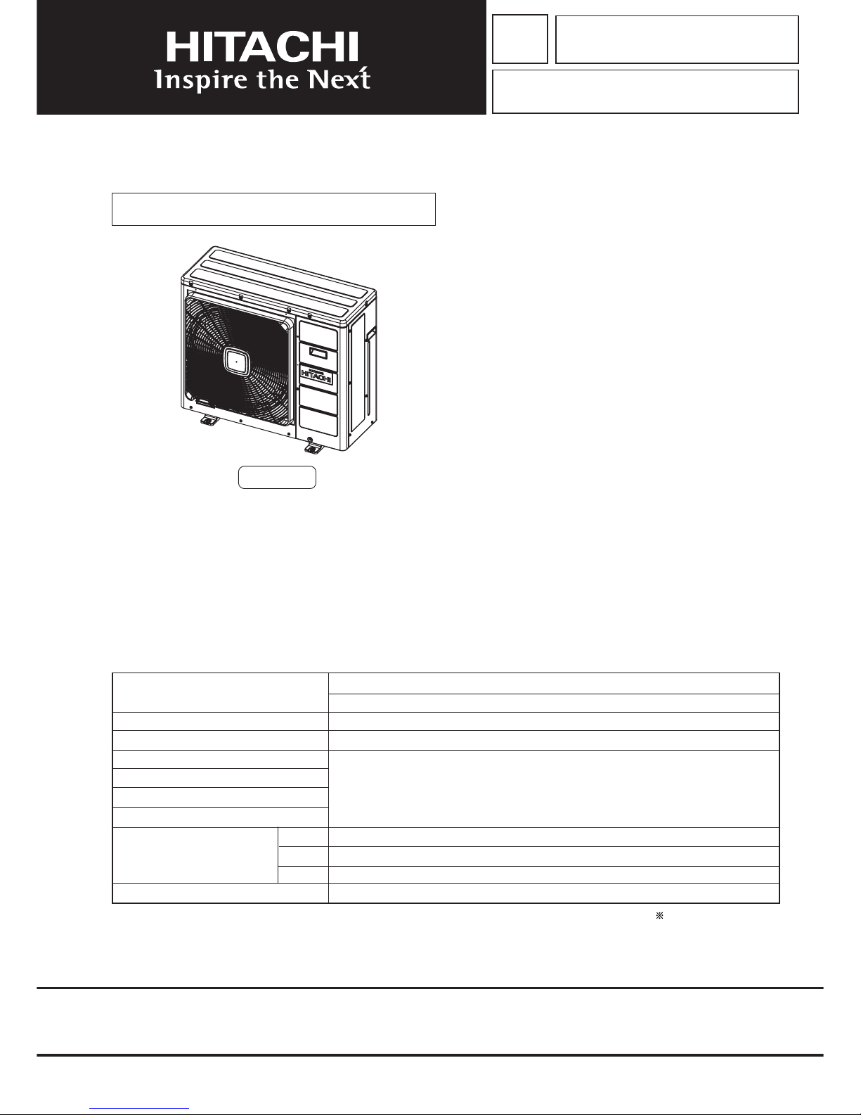
ROOM AIR CONDITIONER
OUTDOOR UNIT
APRIL 2007
Refrigeration & Air-Conditioning Division
SERVICE MANUAL
PM
REFER TO THE FOUNDATION MANUAL
TECHNICAL INFORMATION
FOR SERVICE PERSONNEL ONLY
CONTENTS
SPECIFICATIONS ------------------------------------------------------------------- 5
INSTALLATION --------------------------------------------------------------------- 16
CONSTRUCTION AND DIMENSIONAL DIAGRAM --------------------- 20
WIRING DIAGRAM ---------------------------------------------------------------- 21
MAIN PARTS COMPONENT --------------------------------------------------- 24
CIRCUIT DIAGRAM --------------------------------------------------------------- 25
BLOCK DIAGRAM ----------------------------------------------------------------- 29
BASIC MODE ----------------------------------------------------------------------- 31
REFRIGERATING CYCLE DIAGRAM --------------------------------------- 51
DESCRIPTION OF MAIN CIRCUIT OPERATION ----------------------- 52
TROUBLE SHOOTING ----------------------------------------------------------- 88
PARTS LIST AND DIAGRAM -------------------------------------------------- 94
After installation
(W)
(A)
COOLING CAPACITY
DC INVERTER FIVE SYSTEM MULTI
TYPE
MODEL
POWER SOURCE
TOTAL INPUT
TOTAL AMPERES
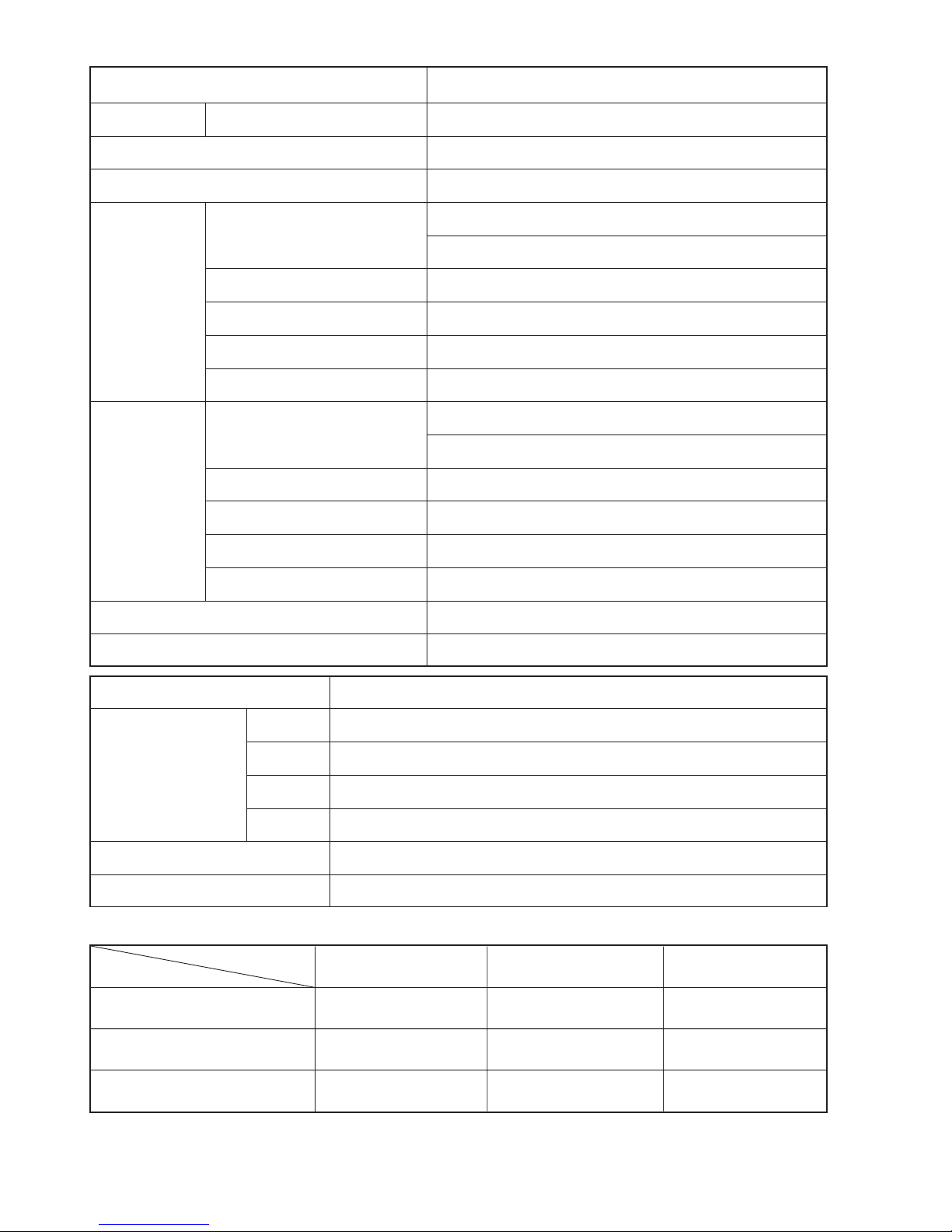
SPECIFICATIONS
RAM-90QH5
HEATING CAPACITY
DIMENSIONS (mm)
NET WEIGHT
1ø, 220 - 240V, 50/60Hz
W
H
D
(kg)
(kW)
(B.T.U.)
REFER TO THE SPECIFICATIONS PAGE
OUTDOOR UNIT
RAM-90QH5
RAM-90QH5
950
800
370
71
NOTE:
This manual describes only points that differ from
PM No. 0322E, PM No. 0355E and PM No. 0366E
for items not described in this manual.
– 1 –
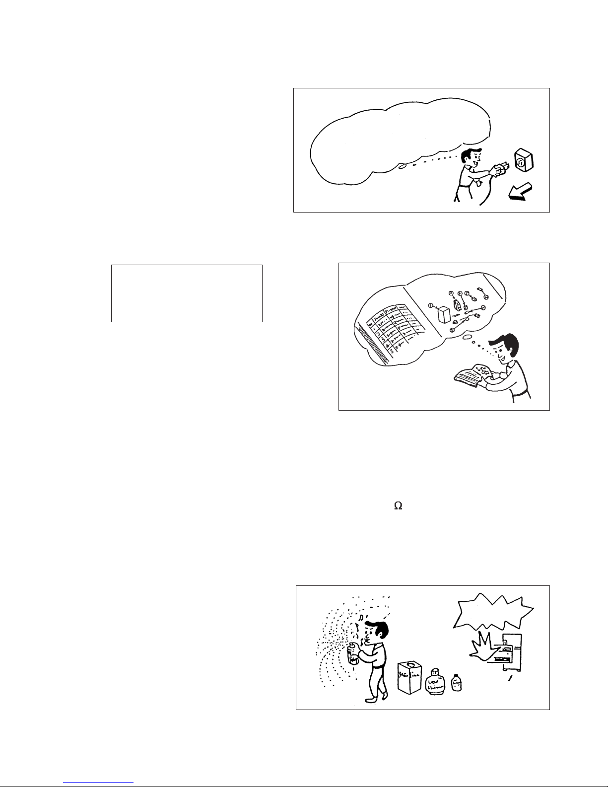
SAFETY DURING REPAIR WORK
1. In order to disassemble and repair
the unit in question, be sure to
disconnect the power cord plug
from the power outlet before starting
the work.
2. If it is necessary to replace any parts, they should be replaced with respective genuine parts for the unit, and
the replacement must be effected in correct manner according to the instructions in the Service Manual of
the unit.
If the contacts of electrical parts
are defective, replace the
electrical parts without trying to
repair them.
3. After completion of repairs, the initial state
should be restored.
4. Lead wires should be connected and laid as
in the initial state.
5. Modification of the unit by user himself should
absolutely be prohibited.
6. Tools and measuring instruments for use in repairs or inspection should be accurately calibrated in advance.
7. In installing the unit having been repaired, be careful to prevent the occurence of any accident such as
electrical shock, leak of current, or bodily injury due to the drop of any part.
8. To check the insulation of the unit, measure the insulation resistance between the power cord plug and
grounding terminal of the unit. The insulation resistance should be 1M or more as measured by a 500V
DC megger.
9. The initial location of installation such as window, floor or the other should be checked for being and safe
enough to support the repaired unit again.
If it is found not so strong and safe, the unit should be installed at the initial location reinforced or at a new
location.
10. Any inflammable thing should never
be placed about the location of
installation.
11. Check the grounding to see whether
it is proper or not, and if it is found
improper, connect the grounding
terminal to the earth.
DANGER
First, I must disconnect
the power cord plug
from the power outlet.
– 2 –
WORKING STANDARDS FOR PREVENTING BREAKAGE OF SEMICONDUCTORS
1. Scope
The standards provide for items to be generally observed in carrying and handling semiconductors in relative
manufacturers during maintenance and handling thereof. (They apply the same to handling of abnormal goods
such as rejected goods being returned).
2. Object parts
(1) Micro computer
(2) Integrated circuits (IC)
(3) Field-effect transistors (FET)
(4) P.C. boards or the like on which the parts mentioned in (1) and (2) of this paragraph are equipped.
3. Items to be observed in handling
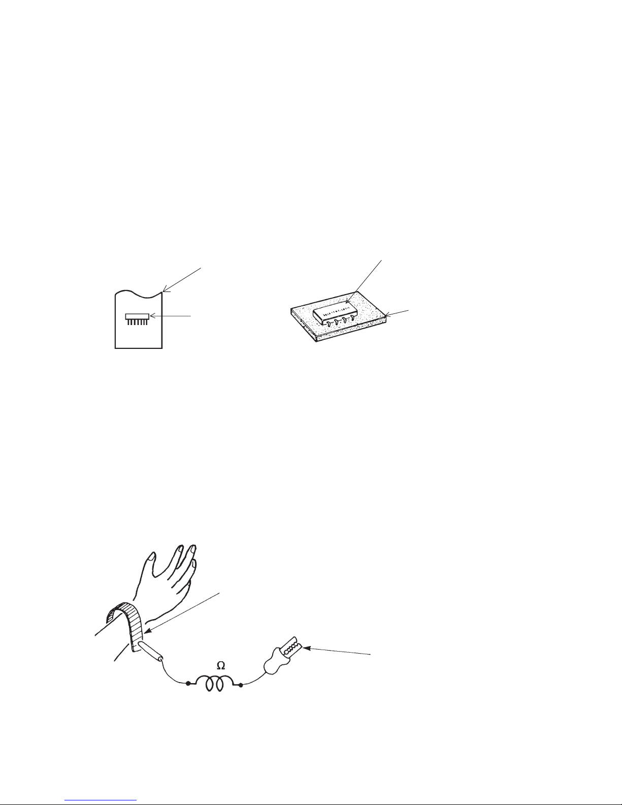
(1) Use a conductive container for carrying and storing of parts. (Even rejected goods should be handled in
the same way).
Fig. 1. Conductive Container
(2) When any part is handled uncovered (in counting, packing and the like), the handling person must always
use himself as a body earth. (Make yourself a body earth by passing one M ohm earth resistance through
a ring or bracelet).
(3) Be careful not to touch the parts with your clothing when you hold a part even if a body earth is being
taken.
(4) Be sure to place a part on a metal plate with grounding.
(5) Be careful not to fail to turn off power when you repair the printed circuit board. At the same time, try
to repair the printed circuit board on a grounded metal plate.
1M
Fig. 2. Body Earth
Body earth
(Elimik conductive band)
Clip for connection with a
grounding wire
IC
A conductive polyvinyl bag
IC
Conductive sponge
– 3 –
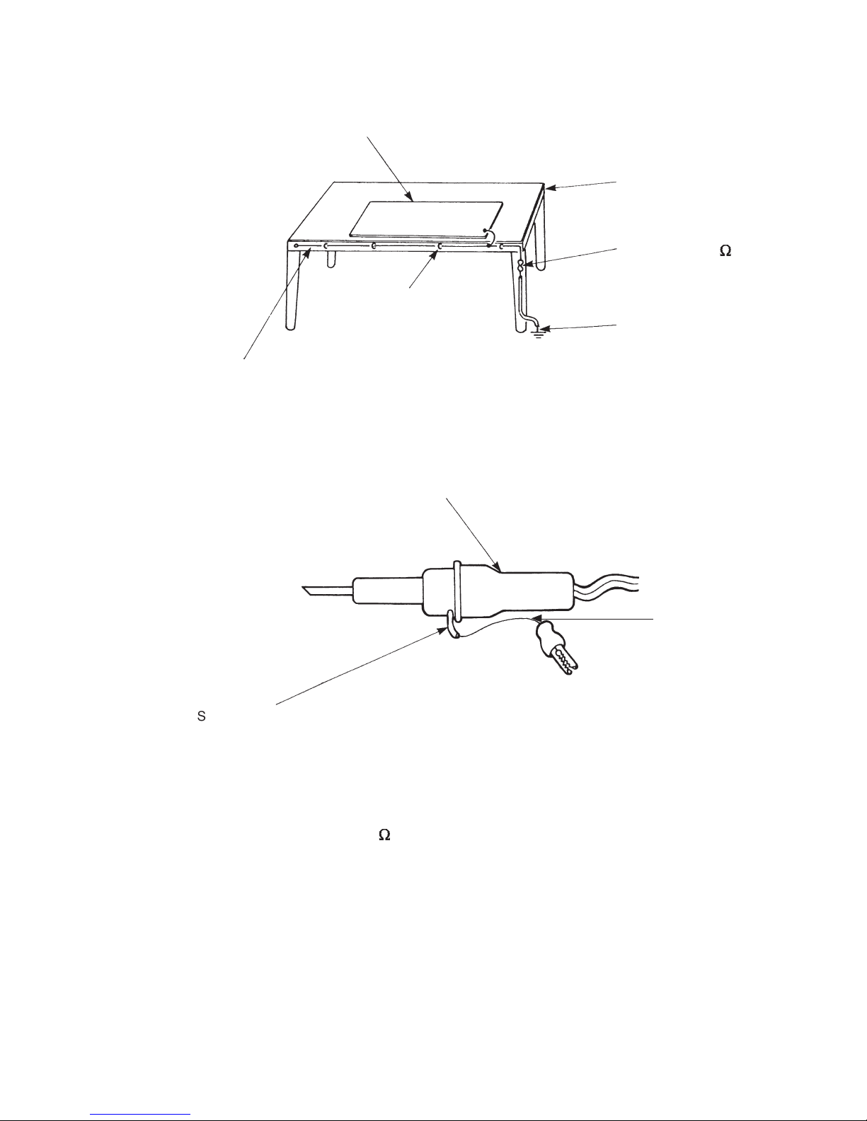
(6) Use a three wire type soldering iron including a grounding wire.
Bare copper wire (for body earth)
Working
table
Resistor of 1 M (1/2W)
Earth wire
Fig. 3. Grounding of the working table
2
Screw stop at the screwed
part using a rag plate
Soldering iron
Grounding
wire
Fig. 4. Grounding a soldering iron
Use a high insulation mode (100V, 10M or higher) when ordinary iron is to be used.
(7) In checking circuits for maintenance, inspection or some others, be careful not to have the test probes of the
measuring instrument shortcircuit a load circuit or the like.
Metal plate (of aluminium, stainless steel, etc.)
Staple

– 4 –
1. In quiet operation or stopping the operation, slight flowing noise of refrigerant in the refrigerating cycle is
heard occasionally, but this noise is not abnormal for the operation.
2. When it thunders near by, it is recommend to stop the operation and to disconnect the power cord plug
from the power outlet for safety.
3. The room air conditioner does not start automatically after recovery of the electric power failure for
preventing fuse blowing. Re-press START/STOP button after 3 minutes from when unit stopped.
4. If the room air conditioner is stopped by setting the temperature, or missoperation, and re-start in a moment,
there is occasion that the cooling and heating operation does not start for 3 minutes, it is not abnormal
and this is the result of the operation of IC delay circuit. This IC delay circuit ensures that there is no
danger of blowing fuse or damaging parts even if operation is restarted accidentally.
5. This room air conditioner should not be used at the cooling operation when the outside temperature is
below –10°C (14°F).
6. This room air conditioner (the reverse cycle) should not be used when the outside temperature is below
–15°C (5°F).
If the reverse cycle is used under this condition, the outside heat exchanger will be frosted and its
efficiency falls.
7. When the outside heat exchanger is frosted, the frost is melted by operating the hot gas system, it is not
trouble that at this time fan stops and the vapour may rise from the outside heat exchanger.
!
CAUTION

– 5 –
SPECIFICATIONS
MODEL
FAN MOTOR
FAN MOTOR CAPACITOR
FAN MOTOR PROTECTOR
COMPRESSOR
COMPRESSOR MOTOR CAPACITOR
OVERLOAD PROTECTOR
OVERHEAT PROTECTOR
FUSE (for MICROPROCESSOR)
POWER RELAY
POWER SWITCH
TEMPORARY SWITCH
SERVICE SWITCH
TRANSFORMER
VARISTOR
NOISE SUPPRESSOR
THERMOSTAT
REMOTE CONTROL SWITCH (LIQUID CRYSTAL)
138 W
NO
NO
NO
YES
YES
5.0A
G4A
NO
NO
YES
NO
450NR
YES
YES(IC)
NO
2700g
WITHOUT REFRIGERANT BECAUSE
COUPLING IS FLARE TYPE.
UNIT
PIPES
REFRIGERANT CHARGING
VOLUME
(Refrigerant 410A)
RAM-90QH5
JU1318D1
MAX. 75m
In case the pipe length is more than 30m, add refrigerant R410 at 15gram per every meter exceeds.
– 6 –
SPECIFICATIONS FOR INDOOR UNITS COMBINATION
OPERATION SCOPE
TYPE
DC INVERTER FIVE SYSTEM MULTI COOLING AND HEATING
MODEL OUTDOOR UNIT
PHESE/VOLTAGE/FREQUENCY
CIRCUIT AMPERES TO CONNECT (A)
COOLING
(FIVE UNITS)
CAPACITY (kW)
(B.T.U./h)
TOTAL INPUT (W)
EER (B.T.U./hW)
TOTAL AMPERES (A)
POWER FACTOR (%)
HEATING
(FIVE UNITS)
CAPACITY (kW)
(B.T.U./h)
TOTAL INPUT (W)
EER (B.T.U./hW)
TOTAL AMPERES (A)
POWER FACTOR (%)
MAXIMUM LENGTH OF PIPING
STANDARD
RAM-90QH5
1ø, 220 - 240V, 50/60Hz
30
9.00 (3.20 - 9.90)
30,720 (10,920 - 33,780)
2,360 (600 - 3,040)
13.02
10.8 - 9.9
99
11.00 (3.40 - 12.10)
37,540 (11,610 - 41,290)
2,460 (610 - 2,910)
15.26
11.3 - 10.4
99
MAX. 75m (FIVE UNIT TOTAL)
CE (EMC&LVD)
RAM-90QH5
MODEL
W
PACKING
(mm)
H
D
cu.ft.
1,073
867
510
16.61
78
GROSS WEIGHT (kg)
6.35DX5/9.52DX3/12.70X2
FLARENUTSIZE (SMALL/LARGE)
INDOOR SUCTION
TEMPERATURE (˚C)
COOLING OPERATION SCOPE
OUTDOOR SUCTION
TEMPERATURE (˚C)
INDOOR SUCTION
HUMIDITY (%)
DEHUMIDIFYING
OPERATION
HEATING OPERATION
SCOPE
16 - 32 –10 ~ 43 BELOW 80
16 - 32 –10 ~ 43 BELOW 80
BELOW 27 –15 ~ 23
—

– 7 –
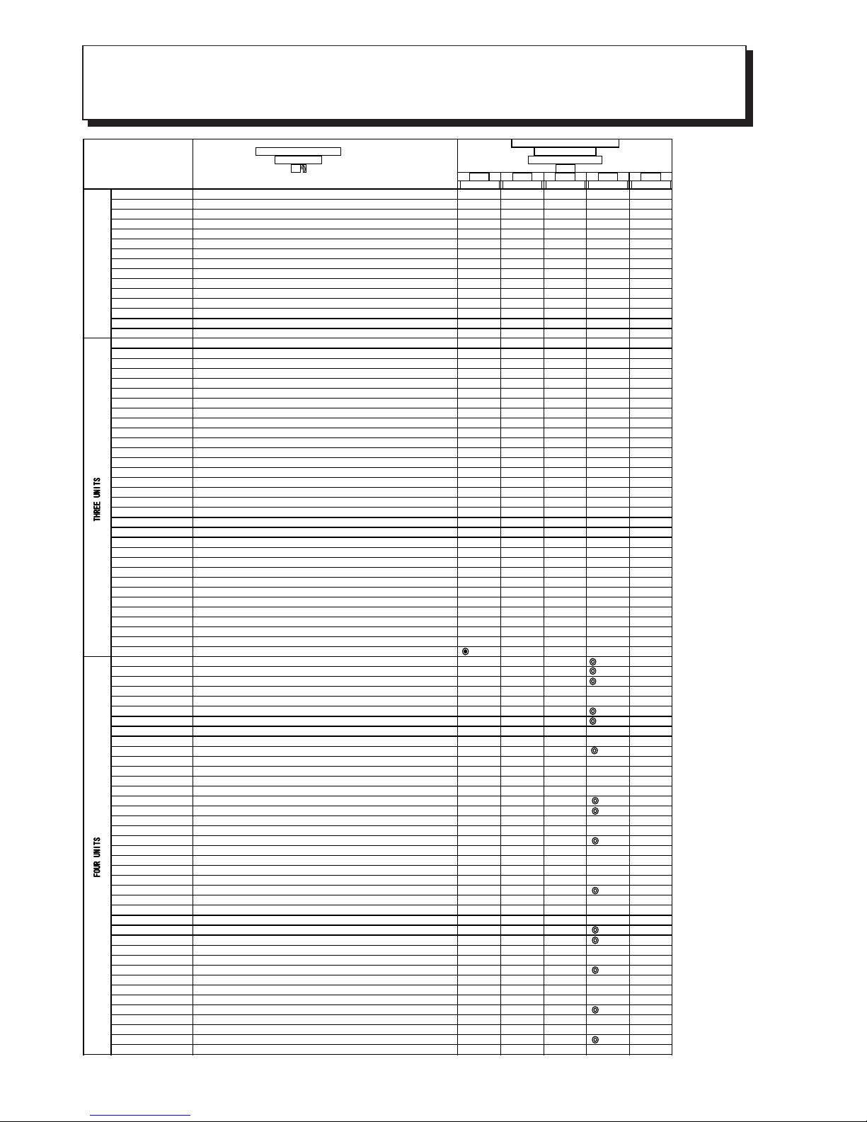
DC INVERTER SYSTEM MULTI R.A.C.
RAM-90QH5
COOL / HEAT CAPACITY SPEC. FOR INDOOR UNITS
COMBINATIONS TO BE ABLE TO OPERATE SIMULTANEOUSLY
Whichever indoor units are installed, cooling and heating capacity depends on how many and which indoor units
are operating at that time.
12.6
2740
3.28
3.32
3.28
3.54
3.32
3.24
3.24
3.27
3.25
2710
2740
2120
2560
2780
2780
2750
2770
11.5
12.4 11.4
12.6 11.5
9.7 8.9
11.8 10.8
12.8 11.7
12.8 11.7
12.6 11.6
12.7 11.7
(Reference value)
5 ROOM MULTI-SPLIT INVERTER TYPE ROOM AIR CONDITIONER
POSSIBLE COMBINATION TO OPERATE (SAME TIME OPERATION)

– 8 –
RATING CONDITON (DRY BLUB / WET BULB)
COOLING
HEATING
INDOOR OUTDOOR
27 / 19 ˚C
20 / –˚C
35 / 24˚C
7 / 6˚C
1.88
1.88 3.22 3.22
1.65 2.85 2.85 2.85
1.56 2.69 2.69 4.06
1.8+3.5+3.5+5.0
1.15+2.30+2.30+3.25
9.00 2530
2.18 2.74 2.74 2.74
<REMARKS>
* ONE UNIT INDICATED ARE ONLY FOR ONE UNIT OPERATION WHEN TWO OR MORE INDOOR UNITS ARE CONNECTED.
* TWO UNITS INDICATED ARE ONLY FOR TWO UNITS OPERATION WHEN TWO OR MORE INDOOR UNITS ARE CONNECTED.
* THREE UNITS INDICATED ARE ONLY FOR THREE UNITS OPERATION WHEN THREE OR MORE INDOOR UNITS ARE CONNECTED.
* FOUR UNITS INDICATED ARE ONLY FOR FOUR UNITS OPERATION WHEN FOUR OR FIVE INDOOR UNITS ARE CONNECTED.

– 9 –
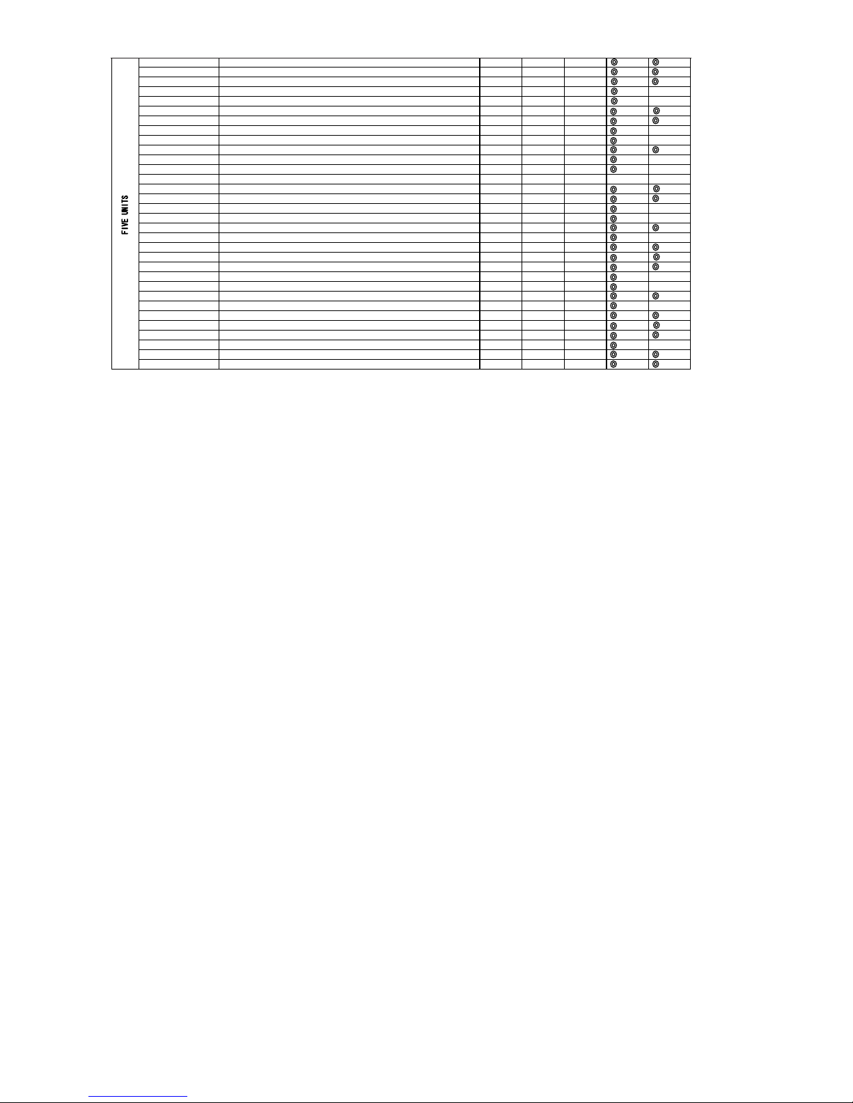
FIVE INVERTER SYSTEM MULTI R.A.C.
RAM-90QH5
INDOOR UNITS COMBINATIONS TO BE ABLE TO INSTALL
Two, three, four or five indoor units can be installed with one outdoor unit.
And total nominal cooling capacity should not be more than 15.5kW
Be sure to connect two or more indoor units to this outdoor unit. If not, condensed water may drop, resulting in
trouble.
INDOOR UNIT
MODEL
NOMINAL
COOLING
CAPACITY
(kW)
CAPACITY (kW)
at one unit operation
SUITABLE ROOM SIZE (m2)
at one unit operation
COOLING HEATING COOLING HEATING
RAK-18NH5
RAK-18NH6
1.8 1.00 - 2.50 1.10 - 3.20
8 - 12 9 - 11
RAK-25NH5
RAK-25NH6
2.5 1.00 - 2.80 1.10 - 4.70
11 - 17 14 - 18
RAF-25NH5
2.5 1.00 - 2.80 1.10 - 4.70
11 - 17 14 - 18
RAD-25NH5
RAD-25NH7
2.5 1.00 - 2.80 1.10 - 4.70
11 - 17 14 - 18
RAI-25NH5
2.5 1.00 - 2.80 1.10 - 4.70
11 - 17 14 - 18
RAK-35NH5
RAK-35NH6
3.5 1.00 - 3.90 1.10 - 5.80
16 - 24 17 - 22
RAF-35NH5 3.5 1.00 - 3.90 1.10 - 5.80
16 - 24 17 - 22
RAD-35NH5
RAD-35NH7
3.5 1.00 - 3.90 1.10 - 5.80
16 - 24 17 - 22
RAI-35NH5
3.5 1.00 - 3.90 1.10 - 5.80
16 - 24 17 - 22
RAK-50NH5
RAK-50NH6
5.0 1.00 - 5.60 1.10 - 7.20
23 - 34 23 - 29
RAF-50NH5
5.0 1.00 - 5.60 1.10 - 7.20
23 - 34 23 - 29
RAI-50NH5
5.0 1.00 - 5.60 1.10 - 7.20
23 - 34 23 - 29
RAD-50NH7
5.0 1.00 - 5.60 1.10 - 7.50
23 - 34 23 - 29
RAK-65NH5
6.0 1.00 - 6.50 1.10 - 9.00
27 - 41 25 - 32
– 10 –
QUADRUPLE SYSTEM MULTI R.A.C.
RAM-90QH5
INDOOR UNITS COMBINATIONS TO BE ABLE TO INSTALL
No. 1 No. 2 No. 3 No. 4 No. 5
6.35/9.52D 6.35/9.52D 6.35/9.52D 6.35/12.7D 6.35/ 12.7D
1.8+1.8 ( 8 ~ 12 ) + ( 8 ~ 12 ) 1.8 1.8
1.8+2.5 ( 8 ~ 12 ) + ( 11 ~ 17 ) 1. 8 2.5
1.8+3.5 ( 8 ~ 12 ) + ( 16 ~ 24 ) 1.8 3.5
1.8+5.0 ( 8 ~ 12 ) + ( 23 ~ 34 ) 1.8 5.0
1.8+6.0 ( 8 ~ 12 ) + ( 27 ~ 41 ) 1.8 6.0
2.5+2.5 ( 11 ~ 17 ) + ( 11 ~ 17 ) 2.5 2.5
2.5+3.5 ( 11 ~ 17 ) + ( 16 ~ 24 ) 2.5 3.5
2.5+5.0 ( 11 ~ 17 ) + ( 23 ~ 34 ) 2.5 5.0
2.5+6.0 ( 11 ~ 17 ) + ( 25 ~ 39 ) 2.5 6.0
3.5+3.5 ( 16 ~ 24 ) + ( 16 ~ 24 ) 3.5 3.5
3.5+5.0 ( 15 ~ 23 ) + ( 21 ~ 32 ) 3.5 5.0
3.5+6.0 ( 14 ~ 21 ) + ( 24 ~ 36 ) 3.5 6.0
5.0+5.0 ( 19 ~ 29 ) + ( 19 ~ 29 ) 5.0 5.0
5.0+6.0 ( 18 ~ 28 ) + ( 21 ~ 32 ) 5.0 6.0
6.0+6.0 ( 20 ~ 31 ) + ( 20 ~ 31 ) 6.0 6.0
1.8+1.8+1. 8 ( 8 ~ 12 ) + ( 8 ~ 12 ) + ( 8 ~ 12 ) 1.8 1.8 1.8
1.8+1.8+2. 5 ( 8 ~ 12 ) + ( 8 ~ 12 ) + ( 11 ~ 17 ) 1.8 1.8 2.5
1.8+1.8+3. 5 ( 8 ~ 12 ) + ( 8 ~ 12 ) + ( 16 ~ 24 ) 1.8 1.8 3.5
1.8+1.8+5. 0 ( 8 ~ 12 ) + ( 8 ~ 12 ) + ( 23 ~ 34 ) 1.8 1.8 5.0
1.8+1.8+6. 0 ( 8 ~ 12 ) + ( 8 ~ 12 ) + ( 26 ~ 39 ) 1.8 1.8 6.0
1.8+2.5+2. 5 ( 8 ~ 12 ) + ( 11 ~ 17 ) + ( 11 ~ 17 ) 1.8 2.5 2.5
1.8+2.5+3. 5 ( 8 ~ 12 ) + ( 11 ~ 17 ) + ( 16 ~ 24 ) 1.8 2.5 3.5
1.8+2.5+5. 0 ( 8 ~ 12 ) + ( 11 ~ 17 ) + ( 22 ~ 33 ) 1.8 2.5 5.0
1.8+2.5+6. 0 ( 7 ~ 11 ) + ( 10 ~ 15 ) + ( 24 ~ 36 ) 1.8 2.5 6.0
1.8+3.5+3. 5 ( 8 ~ 12 ) + ( 16 ~ 24 ) + ( 16 ~ 24 ) 1.8 3.5 3.5
1.8+3.5+5. 0 ( 7 ~ 11 ) + ( 14 ~ 21 ) + ( 20 ~ 30 ) 1.8 3.5 5.0
1.8+3.5+6. 0 ( 7 ~ 10 ) + ( 13 ~ 19 ) + ( 22 ~ 33 ) 1.8 3.5 6.0
1.8+5.0+5. 0 ( 6 ~ 10 ) + ( 17 ~ 26 ) + ( 17 ~ 26 ) 1.8 5.0
1.8+5.0+6. 0 ( 6 ~ 9 ) + ( 16 ~ 24 ) + ( 19 ~ 29 ) 1.8 5.0
1.8+6.0+6. 0 ( 5 ~ 8 ) + ( 18 ~ 27 ) + ( 18 ~ 27 ) 1.8 6.0
2.5+2.5+2. 5 ( 11 ~ 17 ) + ( 11 ~ 17 ) + ( 11 ~ 17 ) 2.5 2.5 2.5
2.5+2.5+3. 5 ( 11 ~ 17 ) + ( 11 ~ 17 ) + ( 16 ~ 24 ) 2.5 2.5 3.5
2.5+2.5+5. 0 ( 10 ~ 16 ) + ( 10 ~ 16 ) + ( 20 ~ 31 ) 2.5 2.5 5.0
2.5+2.5+6. 0 ( 9 ~ 14 ) + ( 9 ~ 14 ) + ( 22 ~ 34 ) 2.5 2.5 6.0
2.5+3.5+3. 5 ( 11 ~ 16 ) + ( 15 ~ 23 ) + ( 15 ~ 23 ) 2.5 3.5 3.5
2.5+3.5+5. 0 ( 9 ~ 14 ) + ( 13 ~ 20 ) + ( 19 ~ 28 ) 2.5 3.5 5.0
2.5+3.5+6. 0 ( 9 ~ 13 ) + ( 12 ~ 18 ) + ( 20 ~ 31 ) 2.5 3.5 6.0
2.5+5.0+5. 0 ( 8 ~ 12 ) + ( 16 ~ 25 ) + ( 16 ~ 25 ) 2.5 5.0 5.0
2.5+5.0+6. 0 ( 8 ~ 12 ) + ( 15 ~ 23 ) + ( 18 ~ 28 ) 2.5 5.0 6.0
2.5+6.0+6. 0 ( 7 ~ 11 ) + ( 17 ~ 26 ) + ( 17 ~ 26 ) 2.5 6.0 6.0
3.5+3.5+3. 5 ( 14 ~ 21 ) + ( 14 ~ 21 ) + ( 14 ~ 21 ) 3.5 3.5 3.5
3.5+3.5+5. 0 ( 12 ~ 18 ) + ( 12 ~ 18 ) + ( 17 ~ 26 ) 3.5 3.5 5.0
3.5+3.5+6. 0 ( 11 ~ 17 ) + ( 11 ~ 17 ) + ( 19 ~ 29 ) 3.5 3.5 6.0
3.5+5.0+5. 0 ( 10 ~ 16 ) + ( 15 ~ 23 ) + ( 15 ~ 23 ) 3.5 5.0 5.0
3.5+5.0+6. 0 ( 10 ~ 15 ) + ( 14 ~ 21 ) + ( 17 ~ 26 ) 3.5 5.0 6.0
3.5+6.0+6. 0 ( 9 ~ 14 ) + ( 16 ~ 24 ) + ( 16 ~ 24 ) 3.5 6.0 6.0
5.0+5.0+5. 0 ( 14 ~ 21 ) + ( 14 ~ 21 ) + ( 14 ~ 21 ) 5.0 5.0 5.0
1.8+1.8+1. 8+1.8 ( 8 ~ 12 ) + ( 8 ~ 12 ) + ( 8 ~ 12 ) + ( 8 ~ 12 ) 1.8 1.8 1.8 1.8
1.8+1.8+1. 8+2.5 ( 8 ~ 12 ) + ( 8 ~ 12 ) + ( 8 ~ 12 ) + ( 11 ~ 17 ) 1.8 1.8 1.8 2.5
1.8+1.8+1. 8+3.5 ( 8 ~ 12 ) + ( 8 ~ 12 ) + ( 8 ~ 12 ) + ( 16 ~ 24 ) 1.8 1.8 1.8 3.5
1.8+1.8+1. 8+5.0 ( 7 ~ 11 ) + ( 7 ~ 11 ) + ( 7 ~ 11 ) + ( 20 ~ 30 ) 1.8 1.8 1.8 5.0
1.8+1.8+1. 8+6.0 ( 6 ~ 10 ) + ( 6 ~ 10 ) + ( 6 ~ 10 ) + ( 22 ~ 33 ) 1.8 1.8 1.8 6.0
1.8+1.8+2. 5+2.5 ( 8 ~ 12 ) + ( 8 ~ 12 ) + ( 11 ~ 17 ) + ( 11 ~ 17 ) 1.8 1.8 2.5 2.5
1.8+1.8+2. 5+3.5 ( 8 ~ 12 ) + ( 8 ~ 12 ) + ( 11 ~ 16 ) + ( 15 ~ 23 ) 1.8 1.8 2.5 3.5
1.8+1.8+2. 5+5.0 ( 7 ~ 10 ) + ( 7 ~ 10 ) + ( 9 ~ 14 ) + ( 19 ~ 28 ) 1.8 1.8 2.5 5.0
1.8+1.8+2. 5+6.0 ( 6 ~ 9 ) + ( 6 ~ 9 ) + ( 8 ~ 13 ) + ( 20 ~ 31 ) 1.8 1.8 2.5 6.0
1.8+1.8+3. 5+3.5 ( 7 ~ 11 ) + ( 7 ~ 11 ) + ( 14 ~ 20 ) + ( 14 ~ 20 ) 1.8 1.8 3.5 3.5
1.8+1.8+3. 5+5.0 ( 6 ~ 9 ) + ( 6 ~ 9 ) + ( 12 ~ 18 ) + ( 17 ~ 26 ) 1.8 1.8 3.5 5.0
1.8+1.8+3. 5+6.0 ( 6 ~ 9 ) + ( 6 ~ 9 ) + ( 11 ~ 17 ) + ( 19 ~ 28 ) 1.8 1.8 3.5 6.0
1.8+1.8+5. 0+5.0 ( 5 ~ 8 ) + ( 5 ~ 8 ) + ( 15 ~ 23 ) + ( 15 ~ 23 ) 1.8 1.8 5.0 5.0
1.8+1.8+5. 0+6.0 ( 5 ~ 8 ) + ( 5 ~ 8 ) + ( 14 ~ 21 ) + ( 17 ~ 26 ) 1.8 1.8 5.0 6.0
1.8+2.5+2. 5+2.5 ( 8 ~ 12 ) + ( 11 ~ 17 ) + ( 11 ~ 17 ) + ( 11 ~ 17 ) 1.8 2.5 2.5 2.5
1.8+2.5+2. 5+3.5 ( 7 ~ 11 ) + ( 10 ~ 15 ) + ( 10 ~ 15 ) + ( 14 ~ 21 ) 1.8 2.5 2.5 3.5
1.8+2.5+2. 5+5.0 ( 6 ~ 10 ) + ( 9 ~ 13 ) + ( 9 ~ 13 ) + ( 17 ~ 26 ) 1.8 2.5 2.5 5.0
1.8+2.5+2. 5+6.0 ( 6 ~ 9 ) + ( 8 ~ 12 ) + ( 8 ~ 12 ) + ( 19 ~ 29 ) 1.8 2.5 2.5 6.0
1.8+2.5+3. 5+3.5 ( 6 ~ 10 ) + ( 9 ~ 14 ) + ( 13 ~ 19 ) + ( 13 ~ 19 ) 1.8 2.5 3.5 3.5
1.8+2.5+3. 5+5.0 ( 6 ~ 9 ) + ( 8 ~ 12 ) + ( 11 ~ 17 ) + ( 16 ~ 24 ) 1.8 2.5 3.5 5.0
1.8+2.5+3. 5+6.0 ( 5 ~ 8 ) + ( 7 ~ 11 ) + ( 10 ~ 16 ) + ( 18 ~ 27 ) 1.8 2.5 3.5 6.0
1.8+2.5+5. 0+5.0 ( 5 ~ 8 ) + ( 7 ~ 11 ) + ( 14 ~ 22 ) + ( 14 ~ 22 ) 1.8 2.5 5.0 5.0
1.8+2.5+5. 0+6.0 ( 5 ~ 8 ) + ( 7 ~ 10 ) + ( 13 ~ 20 ) + ( 16 ~ 24 ) 1.8 2.5 5.0 6.0
1.8+3.5+3. 5+3.5 ( 6 ~ 9 ) + ( 12 ~ 18 ) + ( 12 ~ 18 ) + ( 12 ~ 18 ) 1.8 3.5 3.5 3.5
1.8+3.5+3. 5+5.0 ( 5 ~ 8 ) + ( 10 ~ 16 ) + ( 10 ~ 16 ) + ( 15 ~ 22 ) 1.8 3.5 3.5 5.0
1.8+3.5+3. 5+6.0 ( 5 ~ 8 ) + ( 10 ~ 14 ) + ( 10 ~ 14 ) + ( 17 ~ 26 ) 1.8 3.5 3.5 6.0
1.8+3.5+5. 0+5.0 ( 5 ~ 7 ) + ( 9 ~ 14 ) + ( 13 ~ 20 ) + ( 13 ~ 20 ) 1.8 3.5 5.0 5.0
2.5+2.5+2. 5+2.5 ( 10 ~ 16 ) + ( 10 ~ 16 ) + ( 10 ~ 16 ) + ( 10 ~ 16 ) 2.5 2.5 2.5 2.5
2.5+2.5+2. 5+3.5 ( 9 ~ 14 ) + ( 9 ~ 14 ) + ( 9 ~ 14 ) + ( 13 ~ 20 ) 2.5 2.5 2.5 3.5
2.5+2.5+2. 5+5.0 ( 8 ~ 12 ) + ( 8 ~ 12 ) + ( 8 ~ 12 ) + ( 16 ~ 25 ) 2.5 2.5 2.5 5.0
2.5+2.5+2. 5+6.0 ( 8 ~ 12 ) + ( 8 ~ 12 ) + ( 8 ~ 12 ) + ( 18 ~ 28 ) 2.5 2.5 2.5 6.0
2.5+2.5+3. 5+3.5 ( 9 ~ 13 ) + ( 9 ~ 13 ) + ( 12 ~ 18 ) + ( 12 ~ 18 ) 2.5 2.5 3.5 3.5
2.5+2.5+3. 5+5.0 ( 8 ~ 12 ) + ( 8 ~ 12 ) + ( 11 ~ 16 ) + ( 15 ~ 23 ) 2.5 2.5 3.5 5.0
2.5+2.5+3. 5+6.0 ( 7 ~ 11 ) + ( 7 ~ 11 ) + ( 10 ~ 15 ) + ( 17 ~ 26 ) 2.5 2.5 3.5 6.0
2.5+2.5+5. 0+5.0 ( 7 ~ 10 ) + ( 7 ~ 10 ) + ( 14 ~ 21 ) + ( 14 ~ 21 ) 2.5 2.5 5.0 5.0
2.5+3.5+3. 5+3.5 ( 8 ~ 12 ) + ( 11 ~ 17 ) + ( 11 ~ 17 ) + ( 11 ~ 17 ) 2.5 3.5 3.5 3.5
2.5+3.5+3. 5+5.0 ( 7 ~ 11 ) + ( 10 ~ 15 ) + ( 10 ~ 15 ) + ( 14 ~ 21 ) 2.5 3.5 3.5 5.0
2.5+3.5+3. 5+6.0 ( 7 ~ 10 ) + ( 9 ~ 14 ) + ( 9 ~ 14 ) + ( 16 ~ 24 ) 2.5 3.5 3.5 6.0
3.5+3.5+3. 5+3.5 ( 10 ~ 16 ) + ( 10 ~ 16 ) + ( 10 ~ 16 ) + ( 10 ~ 16 ) 3.5 3.5 3.5 3.5
3.5+3.5+3. 5+5.0 ( 9 ~ 14 ) + ( 9 ~ 14 ) + ( 9 ~ 14 ) + ( 13 ~ 20 ) 3.5 3.5 3.5 5.0
POSSIBLE CO MBINATIONS
TO INSTALL (kW)
TW
OUN
I
TS
(
VALVE DIAMETER
)
(mm)
SUITABLE ROO M SIZE
TO INSTALL
(
m
2
)
CONNECTING POSIT ION ON
OUTDOOR UNIT
– 11 –
2.5, 3.5, 4.0, 5.0 & 6.0 means indoor units cooling capacity class.
(1) Marking
: needs flare adapter (9.52 ➝ 12.7D): Part No. TA261D-4 001
: needs flare adapter (12.7 ➝ 9.52D): Part No. TA261D-6 002
(2) Suitable room size is determined based on the conditions below:
• Climate is in the temperate zone like Tokyo, Japan.
• For usual residential use.
• Smaller figure is for light construction which means light thermally sealed.
• Larger figure is for heavy constructions, which means well thermally sealed.
1.8+1.8+1. 8+1.8+1.8 ( 8 ~ 12 ) + ( 8 ~ 12 ) + ( 8 ~ 12 ) + ( 8 ~ 12 ) + ( 8 ~ 12 ) 1.8 1.8 1.8 1.8 1.8
1.8+1.8+1. 8+1.8+2.5 ( 8 ~ 12 ) + ( 8 ~ 12 ) + ( 8 ~ 12 ) + ( 8 ~ 12 ) + ( 11 ~ 16 ) 1.8 1.8 1.8 1.8 2.5
1.8+1.8+1. 8+1.8+3.5 ( 7 ~ 10 ) + ( 7 ~ 10 ) + ( 7 ~ 10 ) + ( 7 ~ 10 ) + ( 13 ~ 20 ) 1.8 1.8 1.8 1.8 3.5
1.8+1.8+1. 8+1.8+5.0 ( 6 ~ 9 ) + ( 6 ~ 9 ) + ( 6 ~ 9 ) + ( 6 ~ 9 ) + ( 17 ~ 25 ) 1.8 1.8 1.8 1.8 5.0
1.8+1.8+1. 8+1.8+6.0 ( 6 ~ 8 ) + ( 6 ~ 8 ) + ( 6 ~ 8 ) + ( 6 ~ 8 ) + ( 19 ~ 28 ) 1.8 1.8 1.8 1.8 6.0
1.8+1.8+1. 8+2.5+2.5 ( 7 ~ 11 ) + ( 7 ~ 11 ) + ( 7 ~ 11 ) + ( 10 ~ 15 ) + ( 10 ~ 15 ) 1.8 1.8 1.8 2.5 2.5
1.8+1.8+1. 8+2.5+3.5 ( 6 ~ 10 ) + ( 6 ~ 10 ) + ( 6 ~ 10 ) + ( 9 ~ 14 ) + ( 13 ~ 19 ) 1.8 1.8 1.8 2.5 3.5
1.8+1.8+1. 8+2.5+5.0 ( 6 ~ 9 ) + ( 6 ~ 9 ) + ( 6 ~ 9 ) + ( 8 ~ 12 ) + ( 16 ~ 24 ) 1.8 1.8 1.8 2.5 5.0
1.8+1.8+1. 8+2.5+6.0 ( 5 ~ 8 ) + ( 5 ~ 8 ) + ( 5 ~ 8 ) + ( 7 ~ 11 ) + ( 18 ~ 27 ) 1.8 1.8 1.8 2.5 6.0
1.8+1.8+1. 8+3.5+3.5 ( 6 ~ 9 ) + ( 6 ~ 9 ) + ( 6 ~ 9 ) + ( 12 ~ 18 ) + ( 12 ~ 18 ) 1.8 1.8 1.8 3.5 3.5
1.8+1.8+1. 8+3.5+5.0 ( 5 ~ 8 ) + ( 5 ~ 8 ) + ( 5 ~ 8 ) + ( 10 ~ 16 ) + ( 15 ~ 22 ) 1.8 1.8 1.8 3.5 5.0
1.8+1.8+1. 8+3.5+6.0 ( 5 ~ 8 ) + ( 5 ~ 8 ) + ( 5 ~ 8 ) + ( 10 ~ 15 ) + ( 16 ~ 25 ) 1.8 1.8 1.8 3.5 6.0
1.8+1.8+1. 8+5.0+5.0 ( 5 ~ 7 ) + ( 5 ~ 7 ) + ( 5 ~ 7 ) + ( 13 ~ 20 ) + ( 13 ~ 20 ) 1.8 1.8 1.8 5.0 5.0
1.8+1.8+2. 5+2.5+2.5 ( 7 ~ 10 ) + ( 7 ~ 10 ) + ( 9 ~ 14 ) + ( 9 ~ 14 ) + ( 9 ~ 14 ) 1.8 1.8 2.5 2.5 2.5
1.8+1.8+2. 5+2.5+3.5 ( 6 ~ 9 ) + ( 6 ~ 9 ) + ( 8 ~ 13 ) + ( 8 ~ 13 ) + ( 12 ~ 18 ) 1.8 1.8 2.5 2.5 3.5
1.8+1.8+2. 5+2.5+5.0 ( 5 ~ 8 ) + ( 5 ~ 8 ) + ( 8 ~ 11 ) + ( 8 ~ 11 ) + ( 15 ~ 23 ) 1.8 1.8 2.5 2.5 5.0
1.8+1.8+2. 5+2.5+6.0 ( 5 ~ 8 ) + ( 5 ~ 8 ) + ( 7 ~ 11 ) + ( 7 ~ 11 ) + ( 17 ~ 26 ) 1.8 1.8 2.5 2.5 6.0
1.8+1.8+2. 5+3.5+3.5 ( 6 ~ 9 ) + ( 6 ~ 9 ) + ( 8 ~ 12 ) + ( 11 ~ 17 ) + ( 11 ~ 17 ) 1.8 1.8 2.5 3.5 3.5
1.8+1.8+2. 5+3.5+5.0 ( 5 ~ 8 ) + ( 5 ~ 8 ) + ( 7 ~ 11 ) + ( 10 ~ 15 ) + ( 14 ~ 21 ) 1.8 1.8 2.5 3.5 5.0
1.8+1.8+3. 5+3.5+3.5 ( 5 ~ 8 ) + ( 5 ~ 8 ) + ( 10 ~ 15 ) + ( 10 ~ 15 ) + ( 10 ~ 15 ) 1.8 1.8 3.5 3.5 3.5
1.8+2.5+2. 5+2.5+2.5 ( 6 ~ 9 ) + ( 9 ~ 13 ) + ( 9 ~ 13 ) + ( 9 ~ 13 ) + ( 9 ~ 13 ) 1.8 2.5 2.5 2.5 2.5
1.8+2.5+2. 5+2.5+3.5 ( 6 ~ 9 ) + ( 8 ~ 12 ) + ( 8 ~ 12 ) + ( 8 ~ 12 ) + ( 11 ~ 17 ) 1.8 2.5 2.5 2.5 3.5
1.8+2.5+2. 5+2.5+5.0 ( 5 ~ 8 ) + ( 7 ~ 11 ) + ( 7 ~ 11 ) + ( 7 ~ 11 ) + ( 14 ~ 22 ) 1.8 2.5 2.5 2.5 5.0
1.8+2.5+2. 5+2.5+6.0 ( 5 ~ 7 ) + ( 7 ~ 10 ) + ( 7 ~ 10 ) + ( 7 ~ 10 ) + ( 16 ~ 24 ) 1.8 2.5 2.5 2.5 6.0
1.8+2.5+2. 5+3.5+3.5 ( 5 ~ 8 ) + ( 7 ~ 11 ) + ( 7 ~ 11 ) + ( 10 ~ 16 ) + ( 10 ~ 16 ) 1.8 2.5 2.5 3.5 3.5
1.8+2.5+2. 5+3.5+5.0 ( 5 ~ 7 ) + ( 7 ~ 10 ) + ( 7 ~ 10 ) + ( 9 ~ 14 ) + ( 13 ~ 20 ) 1.8 2.5 2.5 3.5 5.0
1.8+2.5+3. 5+3.5+3.5 ( 5 ~ 8 ) + ( 7 ~ 10 ) + ( 10 ~ 15 ) + ( 10 ~ 15 ) + ( 10 ~ 15 ) 1.8 2.5 3.5 3.5 3.5
2.5+2.5+2. 5+2.5+2.5 ( 8 ~ 12 ) + ( 8 ~ 12 ) + ( 8 ~ 12 ) + ( 8 ~ 12 ) + ( 8 ~ 12 ) 2.5 2.5 2.5 2.5 2.5
2.5+2.5+2. 5+2.5+3.5 ( 8 ~ 12 ) + ( 8 ~ 12 ) + ( 8 ~ 12 ) + ( 8 ~ 12 ) + ( 11 ~ 16 ) 2.5 2.5 2.5 2.5 3.5
2.5+2.5+2. 5+2.5+5.0 ( 7 ~ 10 ) + ( 7 ~ 10 ) + ( 7 ~ 10 ) + ( 7 ~ 10 ) + ( 14 ~ 21 ) 2.5 2.5 2.5 2.5 5.0
2.5+2.5+2. 5+3.5+3.5 ( 7 ~ 11 ) + ( 7 ~ 11 ) + ( 7 ~ 11 ) + ( 10 ~ 15 ) + ( 10 ~ 15 ) 2.5 2.5 2.5 3.5 3.5
2.5+2.5+3. 5+3.5+3.5 ( 7 ~ 10 ) + ( 7 ~ 10 ) + ( 9 ~ 14 ) + ( 9 ~ 14 ) + ( 9 ~ 14 ) 2.5 2.5 3.5 3.5 3.5
– 12 –
– 13 –
– 14 –
– 15 –
Fig. 6-1
Fig. 6-2
Fig. 6-3
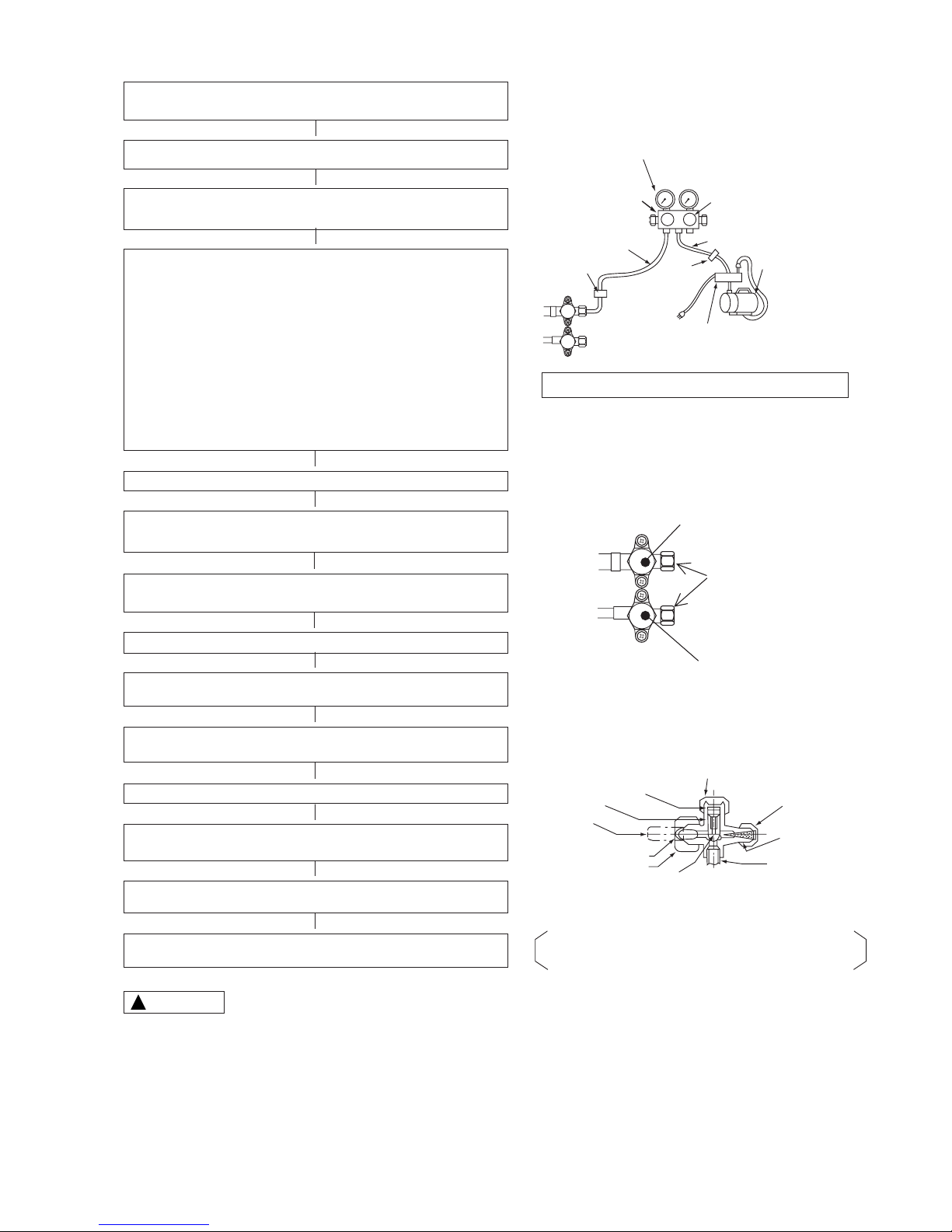
Lo Hi
Stop valve
Charge hose A
Charge hose B
Stop
valve
Vacuum pump adapter
Valve cap
Valve cap
Valve cap of valve core
Valve cap
Valve core
Valve cap of
valve core
Stopper
O-Ring
Pipe
Pipe
Seal cap
Flare nut
Spindle
When the meter reaches -101KPa (-76cmHg) during
pumping, fully tighten the shuttle.
Air purging by vacuum pump
Closed
Vacuum pump
R410A
Manifold valve
Be sure the stop valve is always fully opened.
The refrigerant channel is opened so that the refrigerant
will flow from the outdoor unit into the indoor unit.
Meter showing pressure
Remove the valve cap from the service valves located at both the
large and small pipe rims
➤
Connect the charging hose A to the large service valve.
After connecting the vacuum suction pump adaptor, connect the
charging hose B to the adaptor.
During relocation or re-installed, there is a possibility of electric-powered
valve to be closed. Should the electric-powered valve be closed, even
with air purging being conducted, certain amount of air is still trapped
within that area, hence, there is a need to open up the electric-powered
valve to do an air purging. Under such circumstances, before using
the vacuum-suction pump, the main power supply (LN terminal) should
be connected to enable a complete opening up of the valve. After
connecting the power supply for approximately 90 seconds, the valve
will be fully opened, after which disconnect the power supply and start
using the vacuum suction pump.
(Refer to “Power Supply Terminal Connections” in regards to the LN
terminal)
CAUTION: Ingress of air during the operating cycle may cause increase
in pressure and other breakdowns.
Switch off the outdoor unit’s power supply
Shut the manifold valve handle Hi, handle Lo need to be open and
operate the vacuum pump for approximately 60 minutes.
Upon a full shut of manifold valve handle Lo, the vacuum pump can
be stopped.
Check to ensure that there is no gas leakage.
After removing the charging hose A, rotate the service valve spindles
in an anti-clockwise direction to fully open for both valves.
Reinstall the cap nuts to their original positions and tighten them to
their specified torque.
Disconnect the charge hose from the service valve.
Tighten the valve cap of valve core.
[Torque 12.3 - 15.7 N·m (125 - 160 kgf·cm)]
Fix the valve cap to the spindles of each large and small dia. pipe
side service valves.
Tighten the valve cap of the spindle.
[Torque 19.6 - 24.5 N·m (200 - 250 kgf·cm)]
4. Air purging by using vacuum pump
➤
➤
➤
➤
➤
➤
➤
➤
➤
➤
➤
➤
!
CAUTION
1. Be sure to use the vacuum pump, vacuum pump adapter and manifold gauge and refer to their instruction manuals beforehand.
2. Ascertain that the vacuum pump is filled with oil to the level designated on the oil gauge.
3. After closed the ball valve of charge hose, it should be disconnected at service port side and refrigerant cylinder side at first.
Next, after discharging the remained gas in the charge hose by opening the ball valve a little, disconnect it at manifold gauge side. You
can prevent sudden release of refrigerant by connecting the ball valve to service port. And you can work more safety.
– 16 –
INSTALLATION
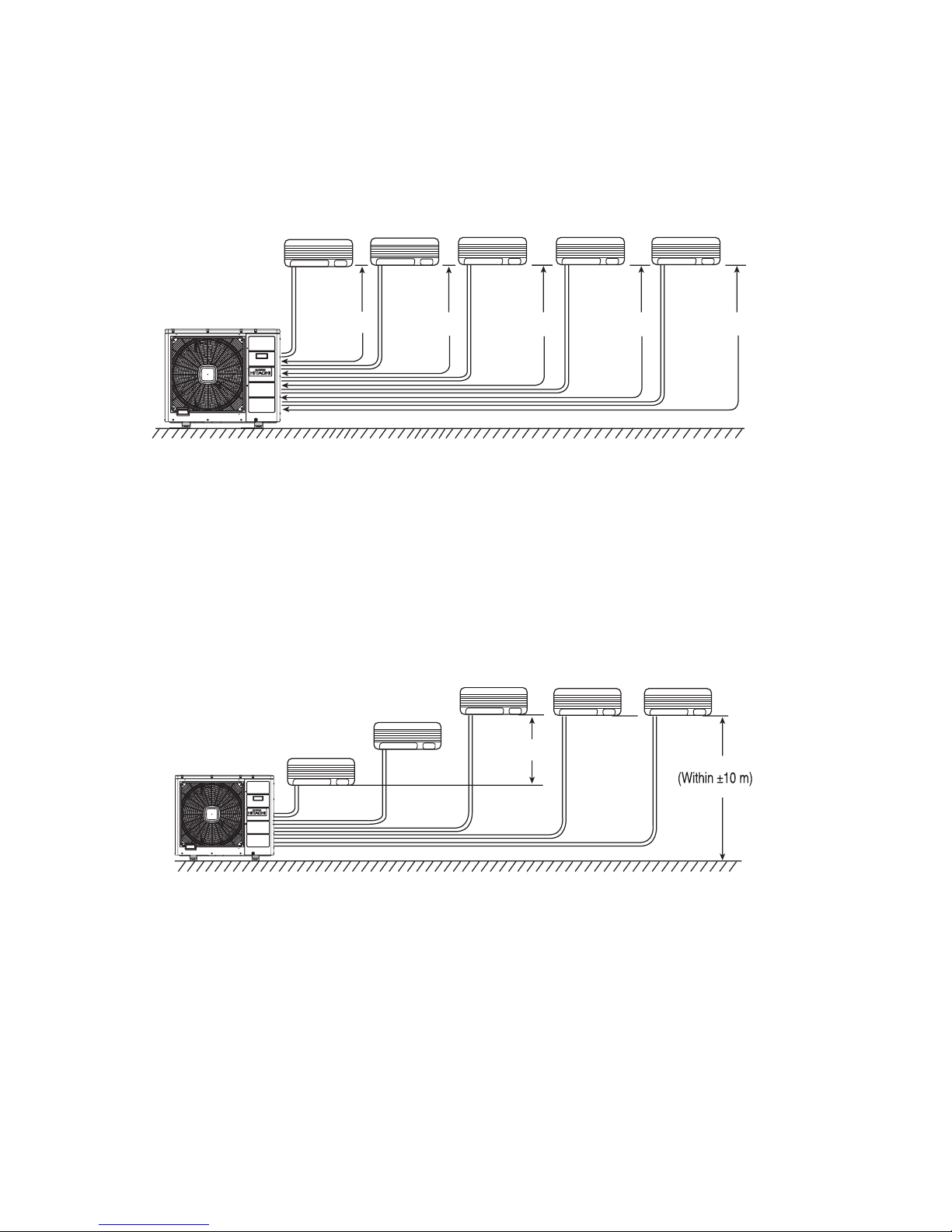
PIPE LENGTH
(1) Total 75m maximum pipe length.
(2) Pipe length for one indoor unit : maximum 25m.
: minimum 5m.
HIGHT DIFFERENCE
(1) Height : maximum ± 10m
(2) Height difference between each indoor unit ≤ 5m.
To the outdoor unit, up to five indoor units can be connected until the total value of capacity to 15.5kW.
Make sure to connect two or more indoor units.
L2
L1
L3
Indoor unit 3L4Indoor unit 4L5Indoor unit 5Indoor unit 2
Indoor unit 1
Outdoor unit
Indoor unit 2
Indoor unit 3
Indoor unit 4
Indoor unit 5
Indoor unit 1
5m
– 17 –
MODEL: RAM-90QH5
Indoor unit 5 Indoor unit 4
Indoor unit 3
Indoor unit 2
Indoor unit 1
Outdoor unit pipe connection port
Dimension of Mounting Stand
of the Outdoor unit
(unit: mm)
700
One unit of 1.8kW, 2.5kW, 3.5kW, 5.0kW or 6.0kW
(5.0kW, 6.0kW unit: Optional flare adaptor for piping is necessary.)
One unit of 1.8kW, 2.5kW, 3.5kW, 5.0kW or 6.0kW
(5.0kW, 6.0kW unit: Optional flare adaptor for piping is necessary.)
One unit of 1.8kW, 2.5kW, 3.5kW, 5.0kW or 6.0kW
(5.0kW, 6.0kW unit: Optional flare adaptor for piping is necessary.)
One unit of 1.8kW, 2.5kW, 3.5kW, 5.0kW, 6.0kW or 7.1kW
(1.8-3.5kW unit: Optional flare adaptor for piping is necessary.)
One unit of 1.8kW, 2.5kW, 3.5kW, 5.0kW, 6.0kW or 7.1kW
(1.8-3.5kW unit: Optional flare adaptor for piping is necessary.)
Face this side (suction
side) of the unit to the wall.
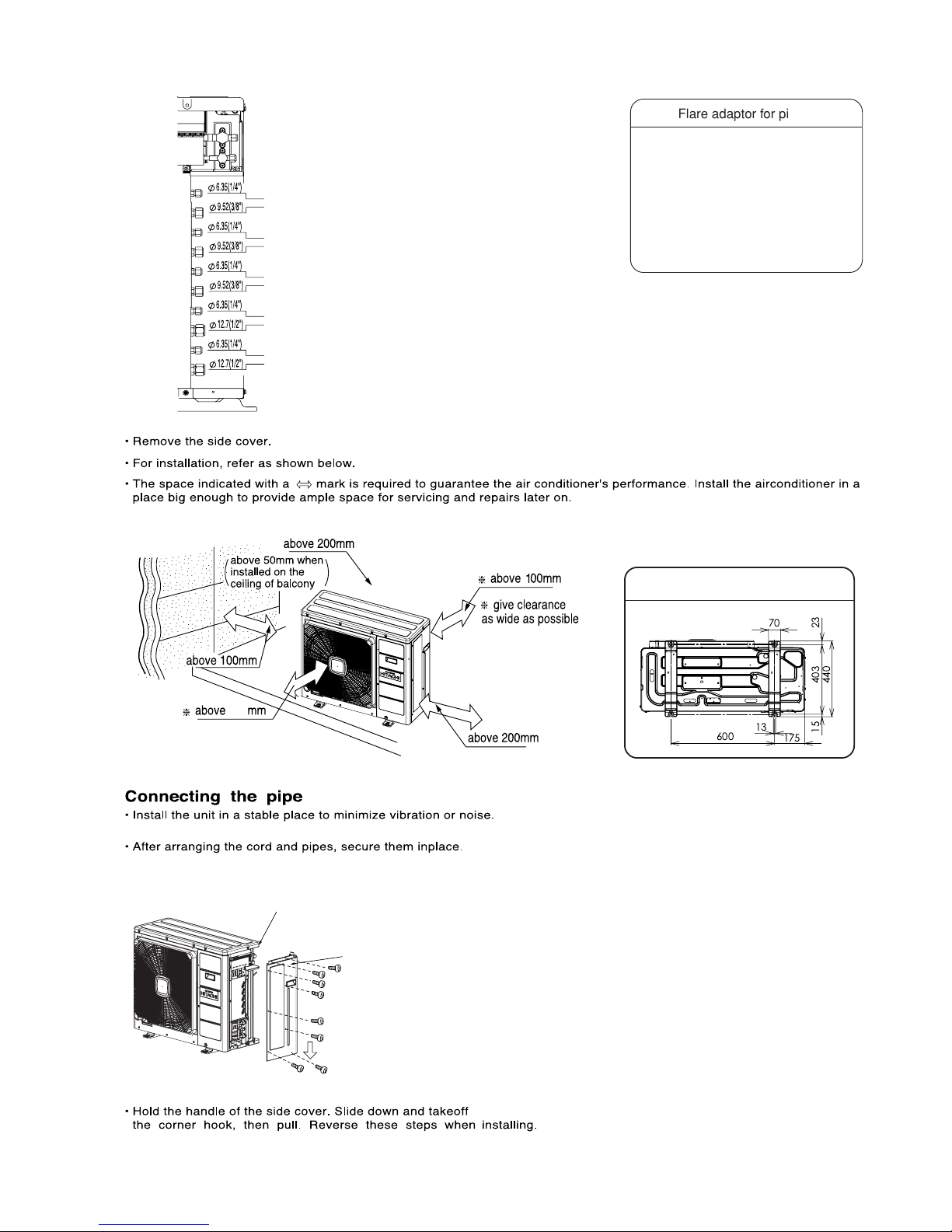
Remove side cover when
connecting the piping and
connecting cord.
Pull downward
13
70
23
44015403
600
175
Flare adaptor for piping
The flare adaptor for piping is
required depending on combination
of indoor units.
•ø9.52 (3/8”) ➝ ø 12.7 (1/2”)
Parts number TA261D-4 001
•ø12.7(1/2”) ➝ ø 9.52 (3/8”)
Parts number TA261D-6 002
•ø12.7(1/2”) ➝ ø 15.88(5/8”)
Parts number TA261D-6 003
– 18 –
BASE
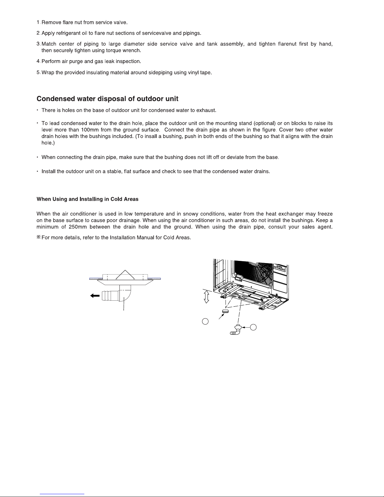
DRAIN PIPE
A
DRAIN PIPE
BUSH
100 mm ABOVE
10
11
– 19 –
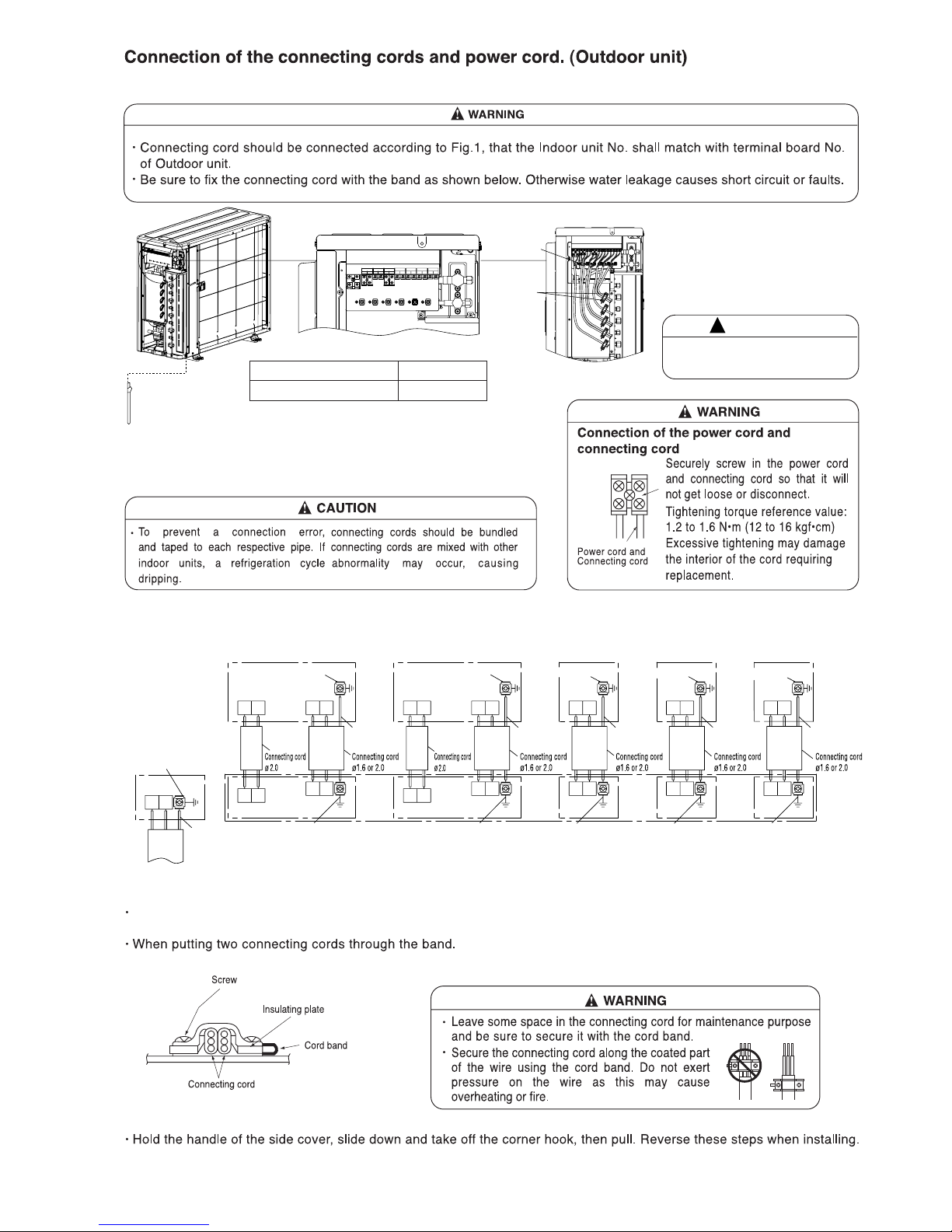
Terminal A and B at Indoor unit 4 and 5 is for 7 kw and 8 kw indoor which using high voltage motor.
Arrange power cord so they do
not touch service valve.
CAUTION
!
Grounding rod (optional)
(Earth wire and grounding rod are not supplied. Please use optional items
below.)
Type of grounding rod
SP-EB-2
Length
900mm
C1 D1C2 D2C3 D3C4 D4A4 B4C5 D5A5 B5
L N
AC200-240V
INDOOR 1INDOOR 2INDOOR 3INDOOR 4INDOOR 4INDOOR 5INDOOR 5
Connect the
earth cord
After remove
the screw
and cover, put
the connecting
cords and fix
the cover with
screw
Wiring Pattern
Indoor Unit
Indoor unit No. 5 Indoor unit No. 4 Indoor unit No. 3 Indoor unit No. 2 Indoor unit No. 1
Screw for ground, earth screw
Screw for ground, earth screw
Terminal
board
Terminal
board
Terminal
board
Terminal
board
Terminal
board
Terminal
board
Terminal
board
Terminal
board
Terminal
board
Terminal
board
Terminal
board
Terminal
board
Terminal
board
Terminal
board
Terminal
board
Power cord
CD
D1C1
CD
D2C2
CD
C3
D3
CD
C4
D4
AB
B4A4
CD
C5 D5
AB
A5 B5
LN
Screw for ground, earth screw
Screw for ground, earth screw
Screw for ground, earth screw
Screw for ground, earth screw
Green-andYellow
Green-andYellow
Green-andYellow
Green-andYellow
Green-andYellow
Green-andYellow
Screw for ground, earth screw
For Indoor unit No. 1
Screw for ground, earth screw
For Indoor unit No. 2
Screw for ground, earth screw
For Indoor unit No. 3
Screw for ground, earth screw
For Indoor unit No. 4
Screw for ground, earth screw
For Indoor unit No. 5
Fig. 1
Outdoor Unit
RAM-90QH5

– 20 –
CONSTRUCTION AND DIMENSIONAL DIAGRAM
MODEL RAM-90QH5
Service space
MODEL RAM-90QH5
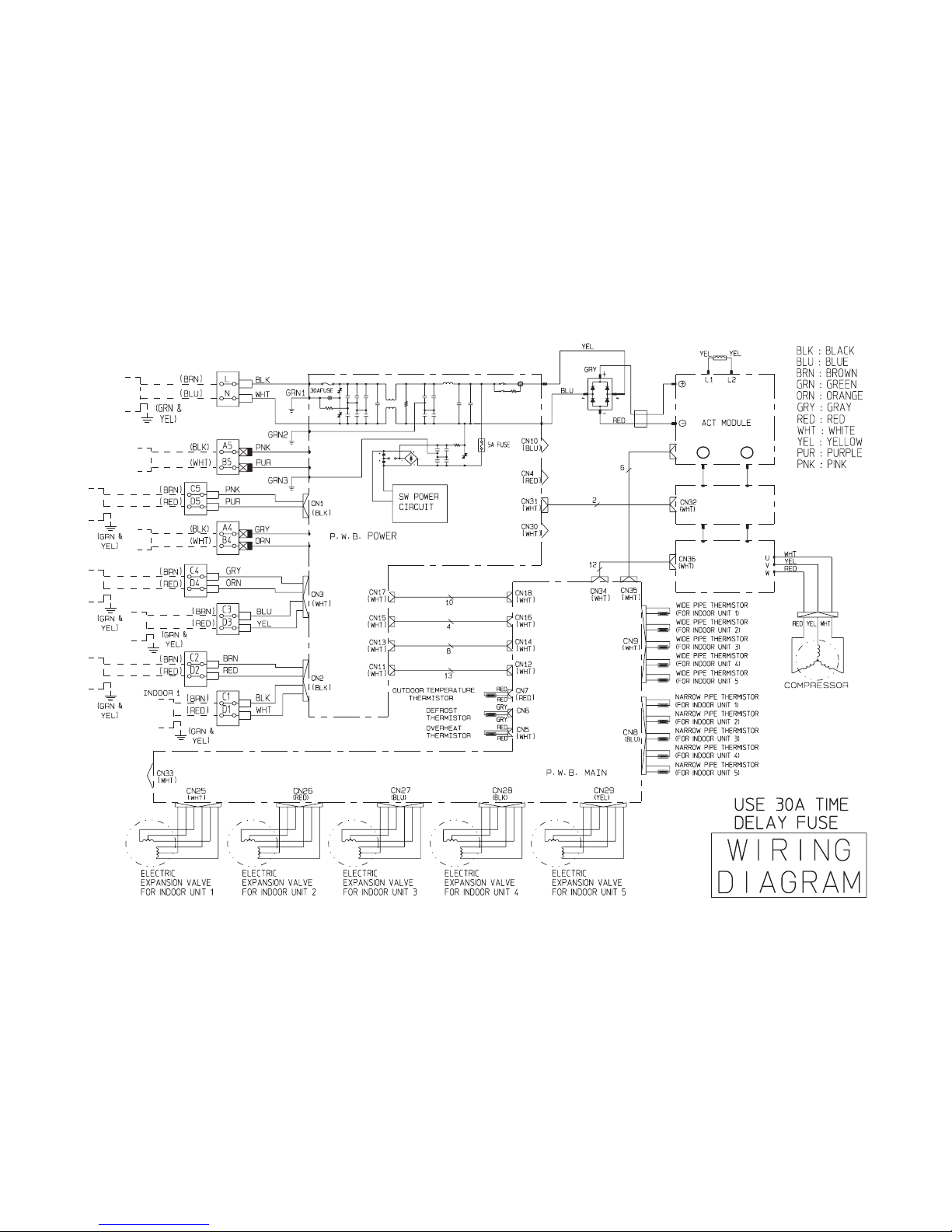
WIRING DIAGRAM
– 21 –
POWER SOURCE
AC220 - 240V
50/60Hz
TERMINAL
BOARD
INDOOR 5
INDOOR 5
INDOOR 4
INDOOR 2
(BLU)
RED GRY
WHT BLK
INDOOR 4
INDOOR 3
Io P
P.W.B. CAPA
P.W.B. IPM
BOARD
TAB 01 TAB 02
– 23 –
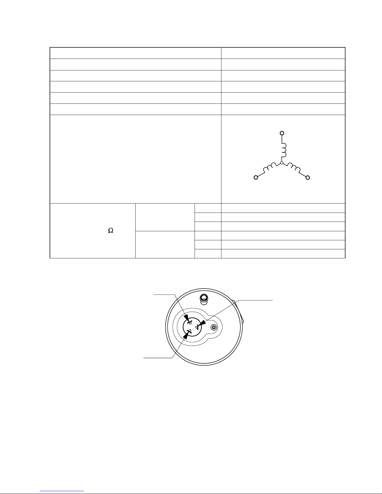
COMPRESSOR MOTOR
Compressor Motor Specifications
MODEL
COMPRESSOR MODEL
PHASE SINGLE
RATED VOLTAGE AC 220 ~ 240 V
RATED FREQUENCY 50/60 Hz
POLE NUMBER 4
CONNECTION
20°C
(68°F)
75°C
(167°F)
( )
RESISTANCE VALUE
0.410
0.397
0.390
RAM-90QH5
JU1318D1
WHITE(U)
(W)
(V)
RED
YELLOW
0.499
0.483
0.474
RED (S)
YELLOW (R)
WHITE (C)
U-V
V-W
W-U
U-V
V-W
W-U
– 24 –
MAIN PARTS COMPONENT
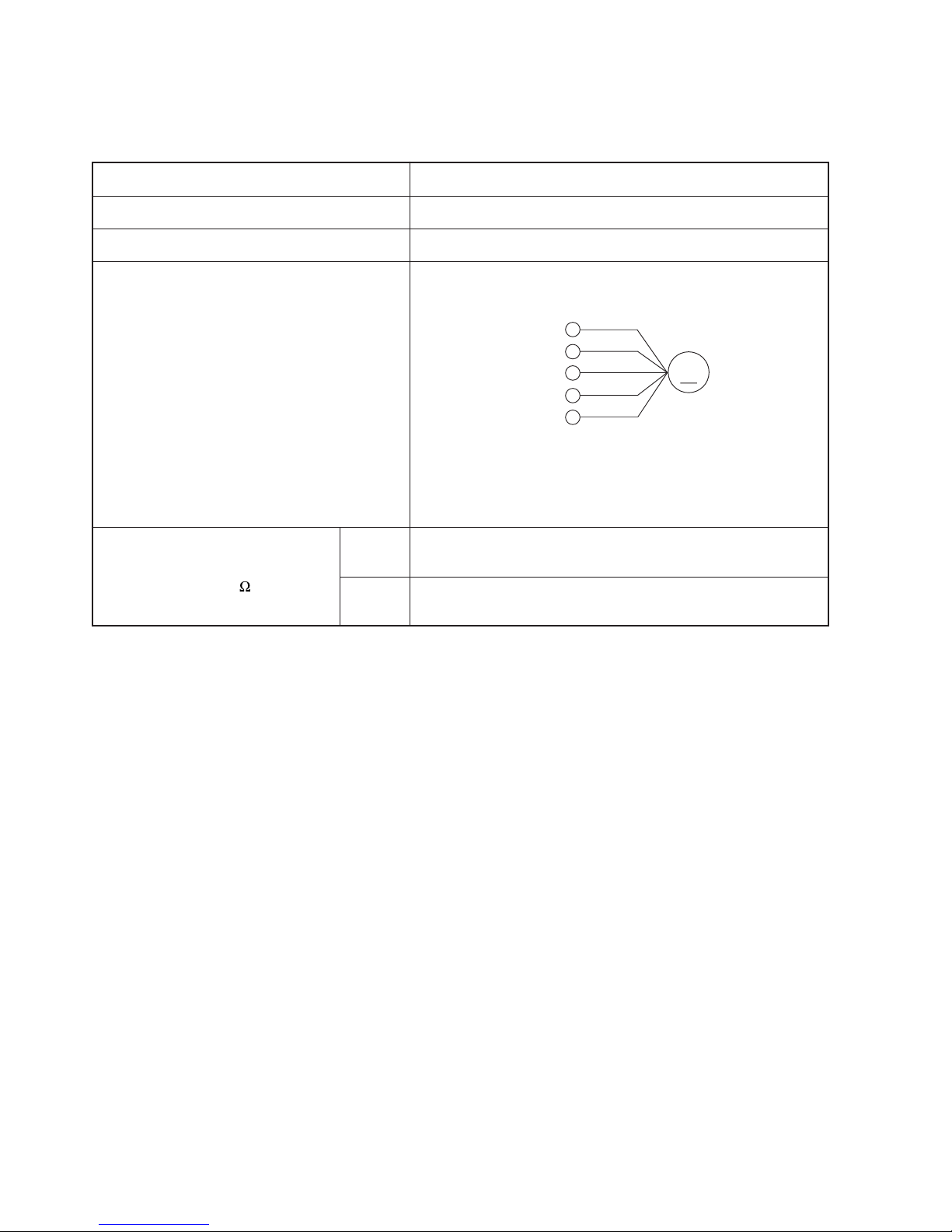
FAN MOTOR
Fan Motor Specifications
CONNECTION
MODEL
POWER SOURCE
OUTPUT
BLU : BLUE YEL : YELLOW BRN : BROWN WHT : WHITE
GRY : GRAY ORN : ORANGE GRN : GREEN RED : RED
BLK : BLACK PNK : PINK VIO : VIOLET
RAM-90QH5
DC : 280V
138W
RESISTANCE VALUE
( )
20˚C
(68˚F)
75˚C
(167˚F)
—
—
M
RED
BLK
WHT
YEL
BLU
(Control circuit built in)
280V
15V
0V
0-6V
0-15V
Remote Control
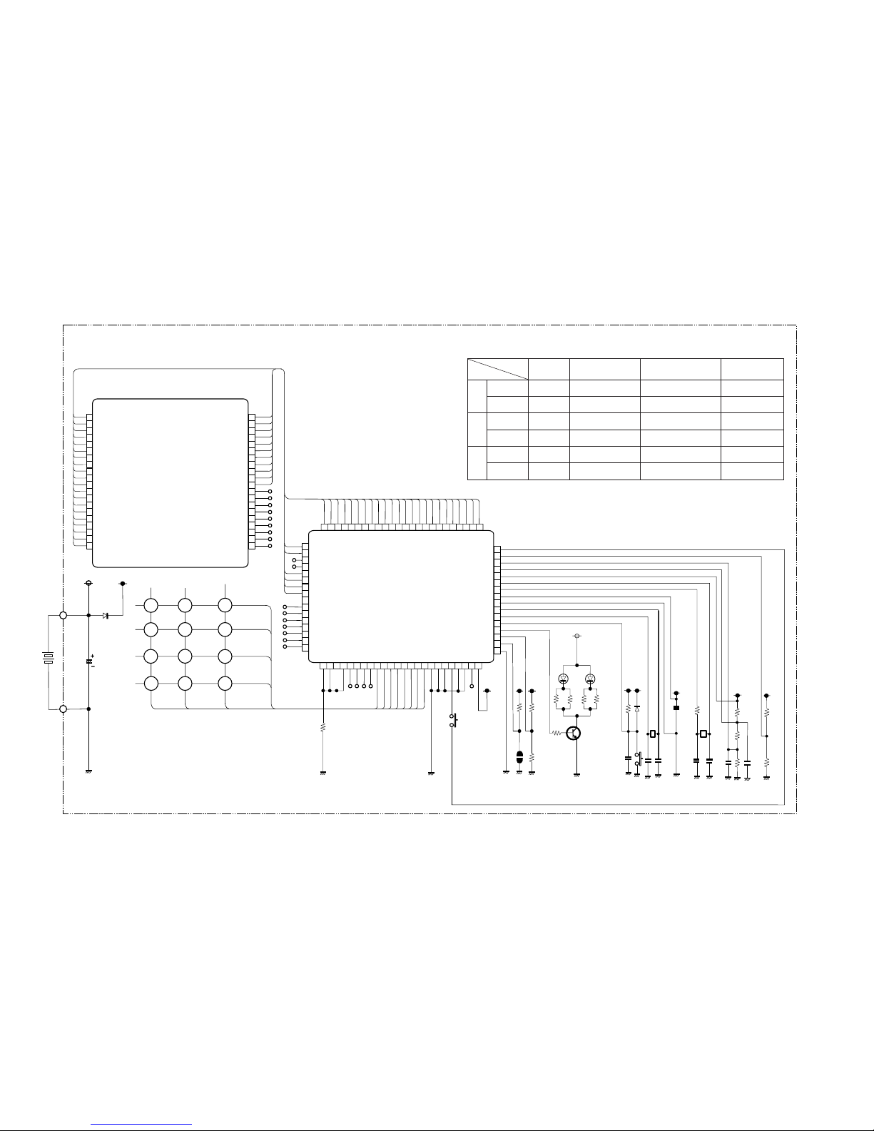
CIRCUIT DIAGRAM
– 25 –
1
2
3
4
5
6
7
8
10
11
13
14
15
16
17
19
20
9
12
18
SEG19
SEG18
SEG17
SEG16
SEG21
SEG24
SEG25
SEG26
SEG27
SEG28
NC
NC
NC
NC
NC
NC
NC
NC
NC
SEG20
SEG5
SEG0
SEG1
SEG2
SEG3
SEG4
SEG5
SEG6
SEG7
COM3
COM2
COM1
COM0
SEG14
SEG13
SEG12
SEG11
SEG13
SEG9
SEG8
40
39
38
37
36
35
34
33
31
30
28
27
26
25
24
22
21
32
29
23
40
39
38
37
36
35
34
33
31
30
28
27
26
25
32
29
64
63
62
61
60
59
58
57
56
55
54
53
52
51
50
49
48 47
46
45
44
43
41
42
65
66
67
68
69
70
71
72
74
75
77
78
79
80
73
76
1
2
3
4
5
6
7
8
9
10
11
12
13
14
15
16
17 18
19
20
21
22
24
23
SEG20
SEG21
SEG22
SEG23
SEG24
SEG25
SEG26
SEG27
SEG28
SEG29
SEG30
SEG31
SEG32
SEG33
SEG34
SEG35
SEG19
SEG18
SEG17
SEG16
SEG15
SEG14
SEG13
SEG12
SEG11
SEG10
SEG9
SEG8
SEG7
SEG6
SEG5
SEG4
SEG3
SEG2
SEG1
SEG0
SEG43
SEG42
SEG41
SEG40
P40
P41
P42
P43
P00
P01
P02
P03
P10
P11
P12
P13
D0
D1
D2
D3
D4
D5
D6
D7
D8
D9
BEEP
P20
P30
P31
NCVL C1
VL C2
VL C3
XC IN
XC OUT
VDD
X OUT
X IN
RESET
CARR
P23
P22
P21
VSS
IC 1
M3455OM6A-504FP
LCD 1
C8
50v/1u
K 1
D3
RB425D(1/2)
K2K3
K4
K5
P10
P11
P12
K6
K7 K8
K9 K10
K11K12
K18
K17
K15 K16
K13 K14
D0
D1
D2
D3
R1
100k
SW1
R2
P
100k
R3
100k
R4
100k
R5
Q1
2SC3443
or 2SC2982
R6
R7
R9
D2D1
D1 D2
EL-1L7
D3
(1/2)
RB425D
R10
12M
K19
X1
C9
R11
R15
R16
R13
R14
910kHz
105
104
104
150k
X2
kHz
C4
C5
C6
C7
18p
22p
R12
220k
220K
220k
100k
100k
32.768
C1
C2
C3
220p
220p
334
R6 R9
24(1/8W)
R8
330
SW-187-2P
Key matrix table
Input
D3D2D1
D0
Output
Door open Automatic swingFan speed selectionOperation selectionStart/Stop
Door shut ––Automatic swingStart/Stop
Door open Day
• present timeHour downHour upOn timer
Door shut Fan speedRoom temperature downRoom temperature up–
Door open CancelReservation–Off timer
Door shut –––Sleep
P10
P11
P12
 Loading...