

Hitachi RAM-71QH5 Service Manual

NO. 0459E
SPECIFICATIONS AND PARTS ARE SUBJECT TO CHANGE FOR IMPROVEMENT
ROOM AIR CONDITIONER
INDOOR UNIT + OUTDOOR UNIT
SEPTEMBER 2009
Refrigeration & Air-Conditioning Division
SERVICE MANUAL
PM
REFER TO THE FOUNDATION MANUAL
TECHNICAL INFORMATION
FOR SERVICE PERSONNEL ONLY
CONTENTS
SPECIFICATIONS ------------------------------------------------------------------- 5
FEATURES -------------------------------------------------------------------------- 17
HOW TO USE ---------------------------------------------------------------------- 21
INSTALLATION --------------------------------------------------------------------- 45
CONSTRUCTION AND DIMENSIONAL DIAGRAM --------------------- 49
MAIN PARTS COMPONENT --------------------------------------------------- 55
WIRING DIAGRAM ---------------------------------------------------------------- 61
CIRCUIT DIAGRAM --------------------------------------------------------------- 67
BLOCK DIAGRAM ----------------------------------------------------------------- 81
BASIC MODE ----------------------------------------------------------------------- 85
REFRIGERATING CYCLE DIAGRAM -------------------------------------- 109
DESCRIPTION OF MAIN CIRCUIT OPERATION ---------------------- 113
TROUBLE SHOOTING ---------------------------------------------------------- 136
SERVICE CALL Q & A --------------------------------------------------------- 185
DISASSEMBLY AND REASSEMBLY --------------------------------------- 201
PARTS LIST AND DIAGRAM ------------------------------------------------- 210
After installation
(W)
(A)
COOLING CAPACITY
DC INVERTER DUAL SYSTEM MULTI
TYPE
MODEL
POWER SOURCE
TOTAL INPUT
TOTAL AMPERES
SPECIFICATIONS
RAM-71QH5
HEATING CAPACITY
DIMENSIONS (mm)
NET WEIGHT
1ø, 220 - 240V, 50Hz
W
H
D
(kg)
(kW)
(B.T.U.)
REFER TO THE SPECIFICATIONS PAGE
OUTDOOR UNIT
RAM-71QH5
RAM-71QH5
850
800
298
55
SAFETY DURING REPAIR WORK
1. In order to disassemble and repair
the unit in question, be sure to
disconnect the power cord plug
from the power outlet before starting
the work.
2. If it is necessary to replace any parts, they should be replaced with respective genuine parts for the unit, and
the replacement must be effected in correct manner according to the instructions in the Service Manual of
the unit.
If the contacts of electrical parts
are defective, replace the
electrical parts without trying to
repair them.
3. After completion of repairs, the initial state
should be restored.
4. Lead wires should be connected and laid as
in the initial state.
5. Modification of the unit by user himself should
absolutely be prohibited.
6. Tools and measuring instruments for use in repairs or inspection should be accurately calibrated in advance.
7. In installing the unit having been repaired, be careful to prevent the occurence of any accident such as
electrical shock, leak of current, or bodily injury due to the drop of any part.
8. To check the insulation of the unit, measure the insulation resistance between the power cord plug and
grounding terminal of the unit. The insulation resistance should be 1M or more as measured by a 500V
DC megger.
9. The initial location of installation such as window, floor or the other should be checked for being and safe
enough to support the repaired unit again.
If it is found not so strong and safe, the unit should be installed at the initial location reinforced or at a new
location.
10. Any inflammable thing should never
be placed about the location of
installation.
11. Check the grounding to see whether
it is proper or not, and if it is found
improper, connect the grounding
terminal to the earth.
DANGER
First, I must disconnect
the power cord plug
from the power outlet.
– 1 –
– 2 –
WORKING STANDARDS FOR PREVENTING BREAKAGE OF SEMICONDUCTORS
1. Scope
The standards provide for items to be generally observed in carrying and handling semiconductors in relative
manufacturers during maintenance and handling thereof. (They apply the same to handling of abnormal goods
such as rejected goods being returned).
2. Object parts
(1) Micro computer
(2) Integrated circuits (IC)
(3) Field-effect transistors (FET)
(4) P.C. boards or the like on which the parts mentioned in (1) and (2) of this paragraph are equipped.
3. Items to be observed in handling
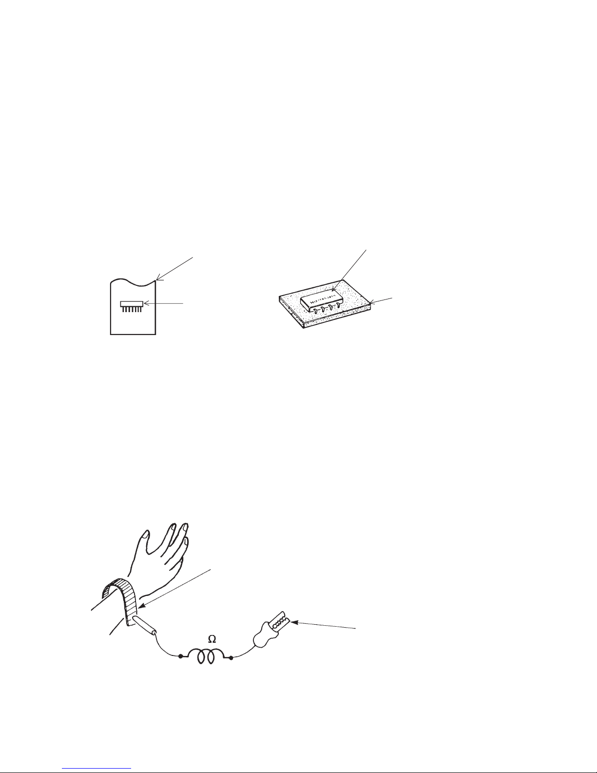
(1) Use a conductive container for carrying and storing of parts. (Even rejected goods should be handled in
the same way).
Fig. 1. Conductive Container
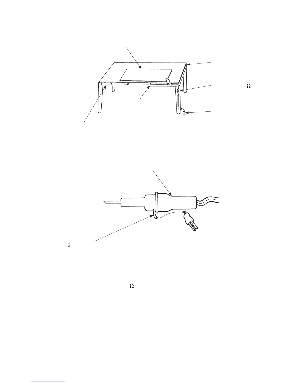
(2) When any part is handled uncovered (in counting, packing and the like), the handling person must always
use himself as a body earth. (Make yourself a body earth by passing one M ohm earth resistance through
a ring or bracelet).
(3) Be careful not to touch the parts with your clothing when you hold a part even if a body earth is being
taken.
(4) Be sure to place a part on a metal plate with grounding.
(5) Be careful not to fail to turn off power when you repair the printed circuit board. At the same time, try
to repair the printed circuit board on a grounded metal plate.
1M
Fig. 2. Body Earth
Body earth
(Elimik conductive band)
Clip for connection with a
grounding wire
IC
A conductive polyvinyl bag
IC
Conductive sponge
– 3 –
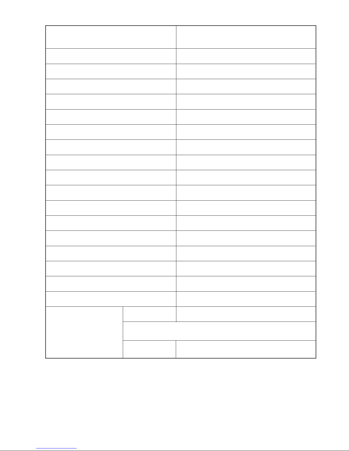
(6) Use a three wire type soldering iron including a grounding wire.
Bare copper wire (for body earth)
Working
table
Resistor of 1 M (1/2W)
Earth wire
Fig. 3. Grounding of the working table
2
Screw stop at the screwed
part using a rag plate
Soldering iron
Grounding
wire
Fig. 4. Grounding a soldering iron
Use a high insulation mode (100V, 10M or higher) when ordinary iron is to be used.
(7) In checking circuits for maintenance, inspection or some others, be careful not to have the test probes of the
measuring instrument shortcircuit a load circuit or the like.
Metal plate (of aluminium, stainless steel, etc.)
Staple

– 4 –
1. In quiet operation or stopping the operation, slight flowing noise of refrigerant in the refrigerating cycle is
heard occasionally, but this noise is not abnormal for the operation.
2. When it thunders near by, it is recommend to stop the operation and to disconnect the power cord plug
from the power outlet for safety.
3. The room air conditioner does not start automatically after recovery of the electric power failure for
preventing fuse blowing. Re-press START/STOP button after 3 minutes from when unit stopped.
4. If the room air conditioner is stopped by setting the temperature, or missoperation, and re-start in a moment,
there is occasion that the cooling and heating operation does not start for 3 minutes, it is not abnormal
and this is the result of the operation of IC delay circuit. This IC delay circuit ensures that there is no
danger of blowing fuse or damaging parts even if operation is restarted accidentally.
5. This room air conditioner should not be used at the cooling operation when the outside temperature is
below –10°C (14°F).
6. This room air conditioner (the reverse cycle) should not be used when the outside temperature is below
–15°C (5°F).
If the reverse cycle is used under this condition, the outside heat exchanger will be frosted and its
efficiency falls.
7. When the outside heat exchanger is frosted, the frost is melted by operating the hot gas system, it is not
trouble that at this time fan stops and the vapour may rise from the outside heat exchanger.
!
CAUTION
– 5 –
SPECIFICATIONS
MODEL
FAN MOTOR
FAN MOTOR CAPACITOR
FAN MOTOR PROTECTOR
COMPRESSOR
COMPRESSOR MOTOR CAPACITOR
OVERLOAD PROTECTOR
OVERHEAT PROTECTOR
FUSE (for MICROPROCESSOR)
POWER RELAY
POWER SWITCH
TEMPORARY SWITCH
SERVICE SWITCH
TRANSFORMER
VARISTOR
NOISE SUPPRESSOR
THERMOSTAT
REMOTE CONTROL SWITCH (LIQUID CRYSTAL)
80 W
NO
NO
NO
YES
YES
5.0A
G4A
NO
NO
YES
NO
450NR
YES
YES(IC)
NO
2300g
WITHOUT REFRIGERANT BECAUSE
COUPLING IS FLARE TYPE.
UNIT
PIPES
REFRIGERANT CHARGING
VOLUME
(Refrigerant 410A)
RAM-71QH5
JU1015D2
MAX. 60m
In case the pipe length is more than 30m, add refrigerant R410 at 20gram per every meter exceeds.
– 6 –
SPECIFICATIONS FOR INDOOR UNITS COMBINATION
OPERATION SCOPE
TYPE
DC INVERTER QUADRUPLE SYSTEM MULTI COOLING AND HEATING
MODEL OUTDOOR UNIT
PHESE/VOLTAGE/FREQUENCY
CIRCUIT AMPERES TO CONNECT (A)
COOLING
(FOUR UNITS)
CAPACITY (kW)
(B.T.U./h)
TOTAL INPUT (W)
EER (B.T.U./hW)
TOTAL AMPERES (A)
POWER FACTOR (%)
HEATING
(FOUR UNITS)
CAPACITY (kW)
(B.T.U./h)
TOTAL INPUT (W)
EER (B.T.U./hW)
TOTAL AMPERES (A)
POWER FACTOR (%)
MAXIMUM LENGTH OF PIPING
STANDARD
RAM-71QH5
1ø, 220 - 240V, 50Hz
30
7.10 (2.40 - 8.80)
24,240 (8,190 - 30,030)
2,140 (460 - 3,200)
11.33
9.8 - 9.0
99
8.50 (2.80 - 9.50)
29,000 (9,560 - 32,420)
2,110 (480 - 3,120)
13.74
9.70 - 8.90
99
MAX. 60m (FOUR UNIT TOTAL)
CE (EMC&LVD)
RAM-71QH5
MODEL
W
PACKING
(mm)
H
D
cu.ft.
1,008
848
394
11.89
60
GROSS WEIGHT (kg)
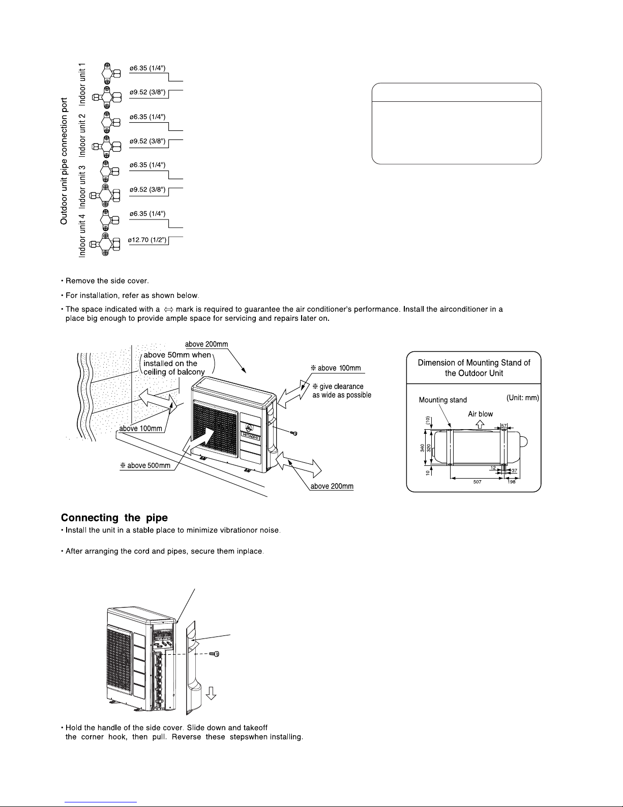
6.35DX4/9.52DX3/12.70X1
FLARENUTSIZE (SMALL/LARGE)
INDOOR SUCTION
TEMPERATURE (˚C)
COOLING OPERATION SCOPE
OUTDOOR SUCTION
TEMPERATURE (˚C)
INDOOR SUCTION
HUMIDITY (%)
DEHUMIDIFYING
OPERATION
HEATING OPERATION
SCOPE
16 - 32 22 - 41 BELOW 80
16 - 32 22 - 42 BELOW 80
BELOW 27 –15 - 23 —
– 7 –
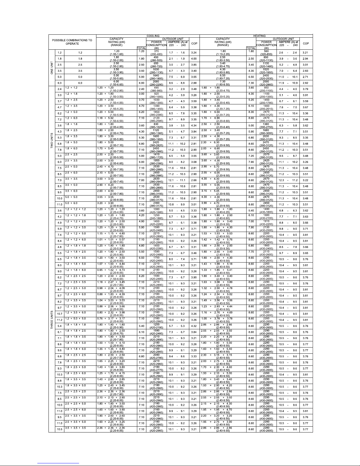
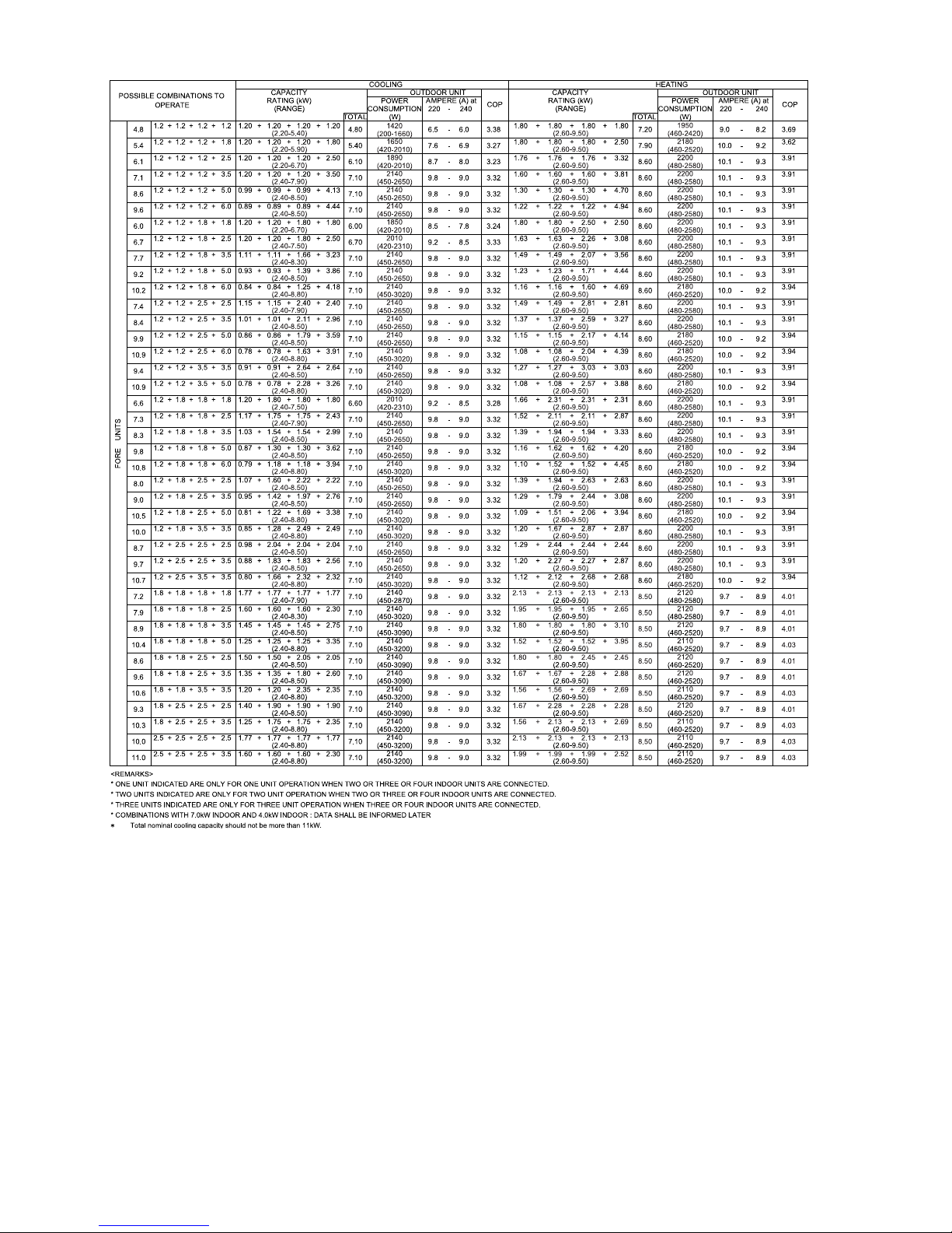
4 ROOM MULTI-SPLIT INVERTER TYPE RAC: RAM-71QH5
POSSIBLE COMBINATION TO OPERATE (SAME TIME OPERATION)
– 8 –
– 9 –
QUADRUPLE SYSTEM MULTI R.A.C.
RAM-71QH5
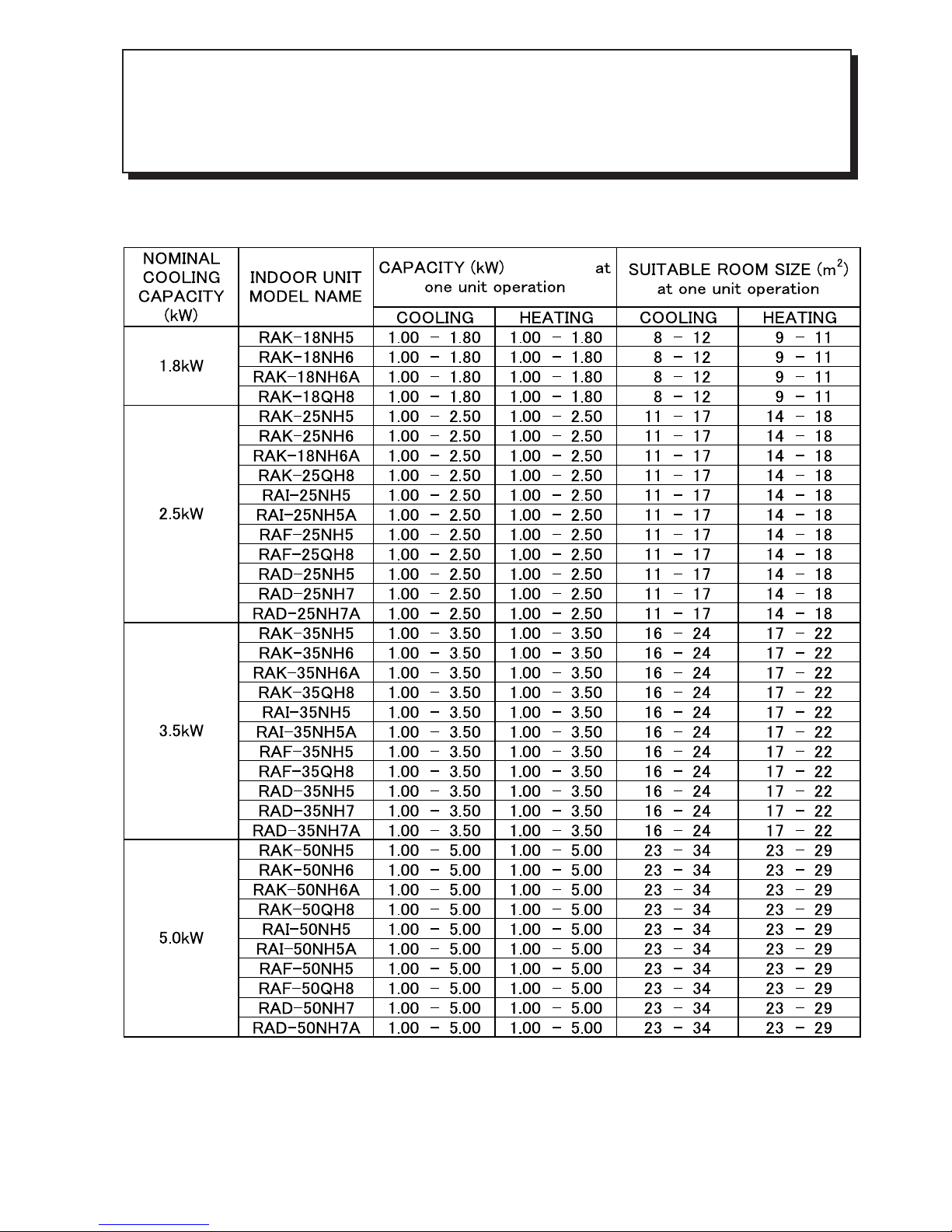
INDOOR UNITS COMBINATIONS TO BE ABLE TO INSTALL
Two, three or four indoor units can be installed with one outdoor unit.
And total nominal cooling capacity should not be more than 11.0kW
Be sure to connect two or three indoor units to this outdoor unit. If not, condensed water may drop, resulting in
trouble.
– 10 –
QUADRUPLE SYSTEM MULTI R.A.C.
RAM-71QH5
INDOOR UNITS COMBINATIONS TO BE ABLE TO INSTALL
POSSIBLE
COMBINATIONS
TO INSTALL
(kW)
CONNECTING POSITION ON
OUTDOOR UNIT
(VALVE DIAMETER) (mm)
No.1 No.2
SUITABLE ROOM SIZE
TO INSTALL
(m
2
)
No.3
6.35/9.52D 6.35/9.52D 6.35/9.52D
TWO UNITS
THREE UNITS
1.8+1.8
1.8+2.5
1.8+3.5
1.8+5.0
1.8+6.0
2.5+2.5
2.5+3.5
2.5+5.0
2.5+6.0
3.5+3.5
3.5+5.0
3.5+6.0
5.0+5.0
5.0+6.0
1.8+1.8+1.8
1.8+1.8+2.5
1.8+1.8+3.5
1.8+1.8+5.0
1.8+1.8+6.0
1.8+2.5+2.5
1.8+2.5+3.5
1.8+2.5+5.0
1.8+2.5+6.0
1.8+3.5+3.5
1.8+3.5+5.0
2.5+2.5+2.5
2.5+2.5+3.5
2.5+2.5+5.0
2.5+2.5+6.0
2.5+3.5+3.5
2.5+3.5+5.0
3.5+3.5+3.5
1.8+1.8+1.8+1.8
1.8+1.8+1.8+2.5
1.8+1.8+1.8+3.5
1.8+1.8+1.8+5.0
1.8+1.8+2.5+2.5
1.8+1.8+2.5+3.5
1.8+1.8+3.5+3.5
1.8+2.5+2.5+2.5
1.8+2.5+2.5+3.5
2.5+2.5+2.5+2.5
2.5+2.5+2.5+3.5
(8 ~ 12) + (8 ~ 12)
(8 ~ 12) + (11 ~ 17)
(8 ~ 12) + (16 ~ 24)
(8 ~ 12) + (23 ~ 34)
(8 ~ 12) + (25 ~ 37)
(11 ~ 17) + (11 ~ 17)
(11 ~ 17) + (16 ~ 24)
(11 ~ 17) + (21 ~ 32)
(10 ~ 14) + (23 ~ 34)
(16 ~ 24) + (16 ~ 24)
(13 ~ 20) + (19 ~ 29)
(12 ~ 18) + (20 ~ 31)
(16 ~ 24) + (16 ~ 24)
(15 ~ 22) + (18 ~ 27)
(8 ~ 12) + (8 ~ 12) + (8 ~ 12)
(8 ~ 12) + (8 ~ 12) + (11 ~ 17)
(8 ~ 12) + (8 ~ 12) + (16 ~ 24)
(7 ~ 10) + (7 ~ 10) + (19 ~ 28)
(6 ~ 9) + (6 ~ 9) + (20 ~ 30)
(8 ~ 12) + (11 ~ 17) + (11 ~ 17)
(8 ~ 11) + (10 ~ 16) + (15 ~ 22)
(6 ~ 10) + (9 ~ 13) + (17 ~ 26)
(6 ~ 9) + (8 ~ 12) + (19 ~ 29)
(6 ~ 10) + (13 ~ 20) + (13 ~ 20)
(6 ~ 9) + (11 ~ 17) + (16 ~ 24)
(11 ~ 16) + (11 ~ 16) + (11 ~ 16)
(10 ~ 14) + (10 ~ 14) + (13 ~ 20)
(8 ~ 12) + (8 ~ 12) + (16 ~ 24)
(7 ~ 11) + (7 ~ 11) + (18 ~ 27)
(9 ~ 13) + (12 ~ 18) + (12 ~ 18)
(7 ~ 11) + (10 ~ 16) + (15 ~ 22)
(11 ~ 16) + (11 ~ 16) + (11 ~ 16)
(8 ~ 12) + (8 ~ 12) + (8 ~ 12) + (8 ~ 12)
(7 ~ 11) + (7 ~ 11) + (7 ~ 11) + (10 ~ 16)
(7 ~ 10) + (7 ~ 10) + (7 ~ 10) + (13 ~ 19)
(6 ~ 9) + (6 ~ 9) + (6 ~ 9) + (15 ~ 23)
(7 ~ 10) + (7 ~ 10) + (9 ~ 14) + (9 ~ 14)
(6 ~ 9) + (6 ~ 9) + (8 ~ 12) + (12 ~ 18)
(5 ~ 8) + (5 ~ 8) + (11 ~ 16) + (11 ~ 16)
(6 ~ 10) + (9 ~ 13) + (9 ~ 13) + (9 ~ 13)
(6 ~ 9) + (8 ~ 12) + (8 ~ 12) + (11 ~ 16)
(8 ~ 12) + (8 ~ 12) + (8 ~ 12) + (8 ~ 12)
(7 ~ 11) + (7 ~ 11) + (7 ~ 11) + (10 ~ 16)
1.8
2.5
3.5
2.5
3.5
3.5
1.8
1.8
1.8
1.8
1.8
2.5
2.5
2.5
2.5
3.5
3.5
2.5
2.5
2.5
2.5
3.5
3.5
3.5
1.8
1.8
1.8
1.8
1.8
1.8
1.8
2.5
2.5
2.5
2.5
1.8
2.5
3.5
2.5
3.5
3.5
2.5
3.5
3.5
3.5
1.8
1.8
1.8
1.8
2.5
2.5
3.5
2.5
2.5
2.5
2.5
2.5, 3.5, 4.0, 5.0 & 6.0 means indoor units cooling capacity class.
(1) Marking
: needs flare adapter (9.52 ➝ 12.7D): Part No. TA261D-4 001
: needs flare adapter (12.7 ➝ 9.52D): Part No. TA261D-6 002
(2) Suitable room size is determined based on the conditions below:
• Climate is in the temperate zone like Tokyo, Japan.
• For usual residential use.
• Smaller figure is for light construction which means light thermally sealed.
• Larger figure is for heavy constructions, which means well thermally sealed.
No.4
6.35/12.7D
5.0
6.0
5.0
6.0
5.0
6.0
5.0
6.0
5.0
6.0
5.0
6.0
5.0
5.0
6.0
5.0
1.8
2.5
3.5
5.0
2.5
3.5
3.5
2.5
3.5
2.5
3.5
1.8
1.8
1.8
1.8
1.8
2.5
2.5
2.5
2.5
3.5
3.5
3.5
5.0
5.0
1.8
1.8
1.8
1.8
1.8
1.8
1.8
1.8
1.8
1.8
1.8
2.5
2.5
2.5
2.5
2.5
2.5
3.5
1.8
1.8
1.8
1.8
1.8
1.8
1.8
1.8
1.8
2.5
2.5
FOUR UNITS
– 11 –
– 12 –

– 13 –
– 14 –
– 15 –
Outdoor unit
Maximum 5m
Indoor unit
Indoor unit
Indoor unit
Indoor unit
INSTALLATION
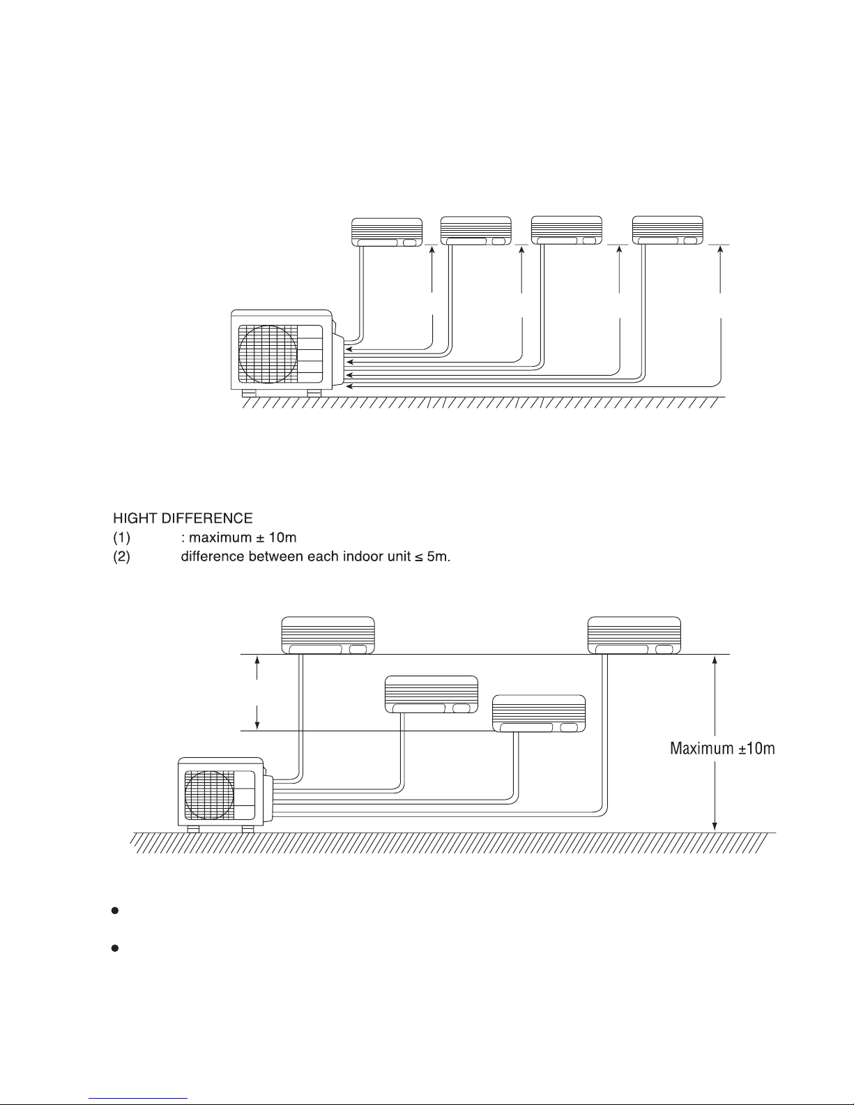
PIPE LENGTH
(1) Total 60m maximum pipe length.
(2) Pipe length for one indoor unit : maximum 25m.
To the outdoor unit, up to four indoor units can be connected until the total value of
capacity to 11.0kW.
Make sure to connect to two or more indoor units.
L2
L1
L3
Indoor unit 3
L4
Indoor unit 4Indoor unit 2
Indoor unit 1
Outdoor unit
Height
Height
– 16 –
MODEL: RAM-71QH5
Flare adaptor for piping
The flare adaptor for piping is required
depending on combination of indoor units.
•ø9.52 (3/8”) ➝ ø 12.7 (1/2”)
Parts number TA261D-4 001
•ø12.7(1/2”) ➝ ø 9.52 (3/8”)
Parts number TA261D-6 002
One unit of 1.8kW, 2.5kW,
3.5kW or 5.0kW
One unit of 1.8kW, 2.5kW, 3.5kW or 5.0kW
(5kW unit: Optional flare adaptor for piping
is necessary.)
One unit of 1.8kW, 2.5kW, 3.5kW, 5.0kW or
6.0kW
(5kW, 6kW unit: Optional flare adaptor for
piping is necessary.)
One unit of 1.8kW, 2.5kW, 3.5kW, 5.0kW or
6.0kW
(2.5kW, 3.5kW unit: Optional flare adaptor
for piping is necessary.)
Face this side (suction side) of
the unit to the wall.
Remove side cover
when connecting the
piping and connecting
cord.
Pull downward
– 17 –
– 18 –
RAM-71QH5
Grounding rod (optional)
(Earth wire and grounding rod are not supplied. Please use optional
items below.)
Earth line
Arrange power cord so they do
not touch service valve.
CAUTION
!
– 19 –
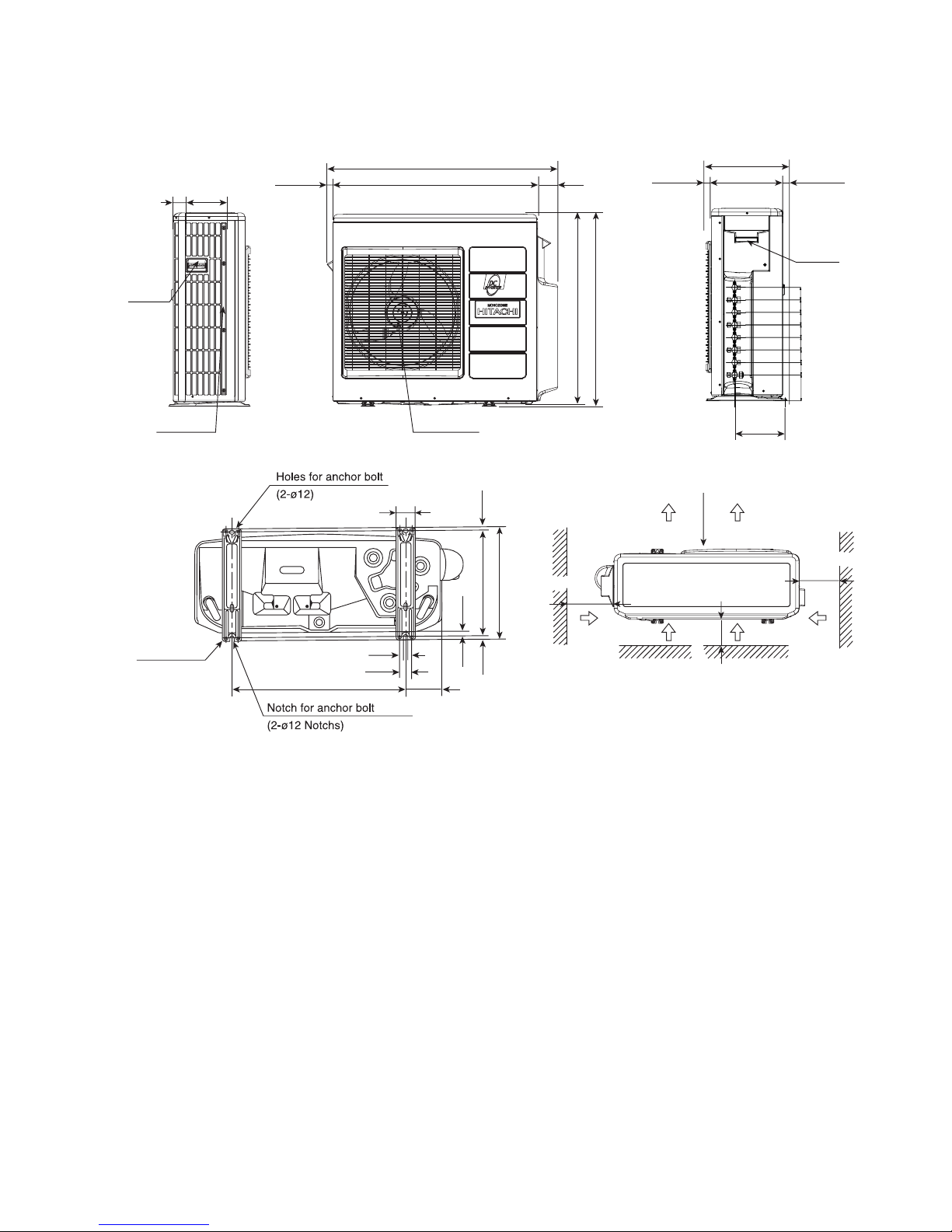
CONSTRUCTION AND DIMENSIONAL DIAGRAM
MODEL RAM-71QH5
Handle
Air suction
grille
16874
26 850
957
81
800
788
1010
10
320
340
Air outlet
340
2022 298
211
Handle
Fixing hole
507 198
57
12
37
More than
More than
More than
100
More than
700
100
100
Service space
52
52
107.5
52
52 52
52
52
– 20 –
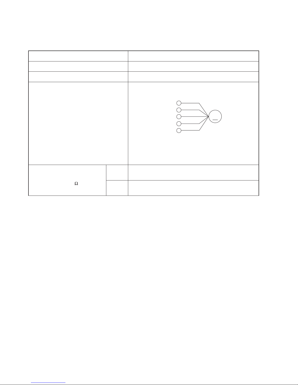
MAIN PARTS COMPONENT
FAN MOTOR
Fan Motor Specifications
CONNECTION
MODEL
POWER SOURCE
OUTPUT
BLU : BLUE YEL : YELLOW BRN : BROWN WHT : WHITE
GRY : GRAY ORN : ORANGE GRN : GREEN RED : RED
BLK : BLACK PNK : PINK VIO : VIOLET
DC : 350V
80W
RESISTANCE
VALUE
( )
20˚C
(68 ˚F)
75
˚C
(167 ˚F)
—
—
MM
WHT
BLK
RED
YEL
BLU
(Control circuit built in)
350V
15V
0V
0-6V
0-15V
RAM-71QH5
– 21 –
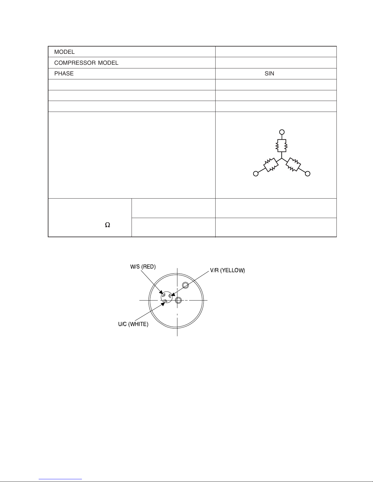
COMPRESSOR MOTOR
Compressor Motor Specifications
V/R (YELLOW)
W/S (RED)
U/C (WHITE)
MODEL
COMPRESSOR MODEL
PHASE SINGLE
RATED VOLTAGE AC 220 ~ 240 V
RATED FREQUENCY 50 Hz
POLE NUMBER 4
CONNECTION
20°C
(68°F)
75°C
(167°F)
( )
RESISTANCE VALUE
2M = 1.05
2M = 1.268
RAM-71QH5
JU1015D2
U
V
W
WHITE
M
M
M
YELLOW
RED
MODEL RAM-71QH5
WIRING DIAGRAM
– 23 –
GRY
WHT
RED
YEL
BLK
ORN
GRY
WHT
RED
YEL
BLK
ORN
GRY
WHT
RED
YEL
BLK
ORN
GRY
WHT
RED
YEL
BLK
ORN
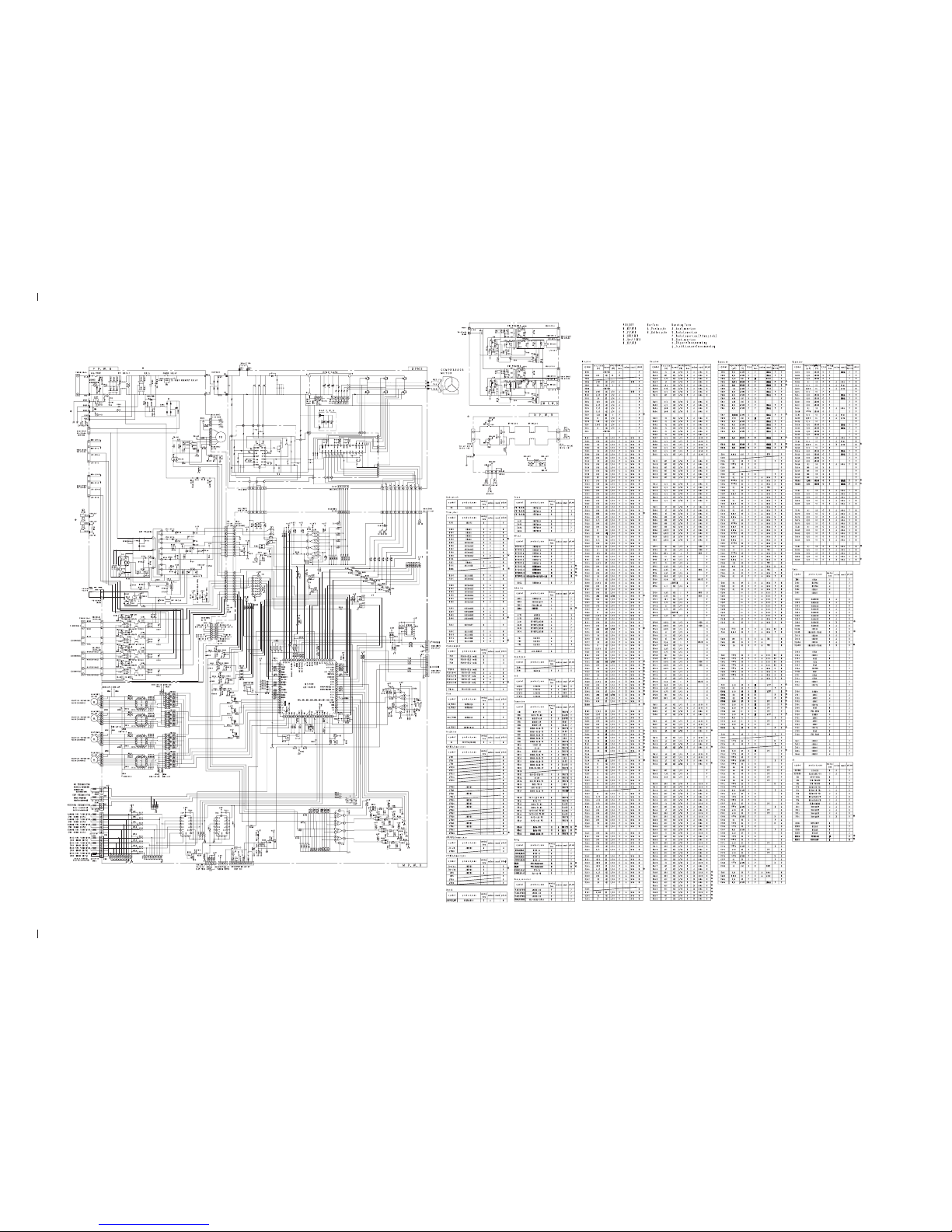
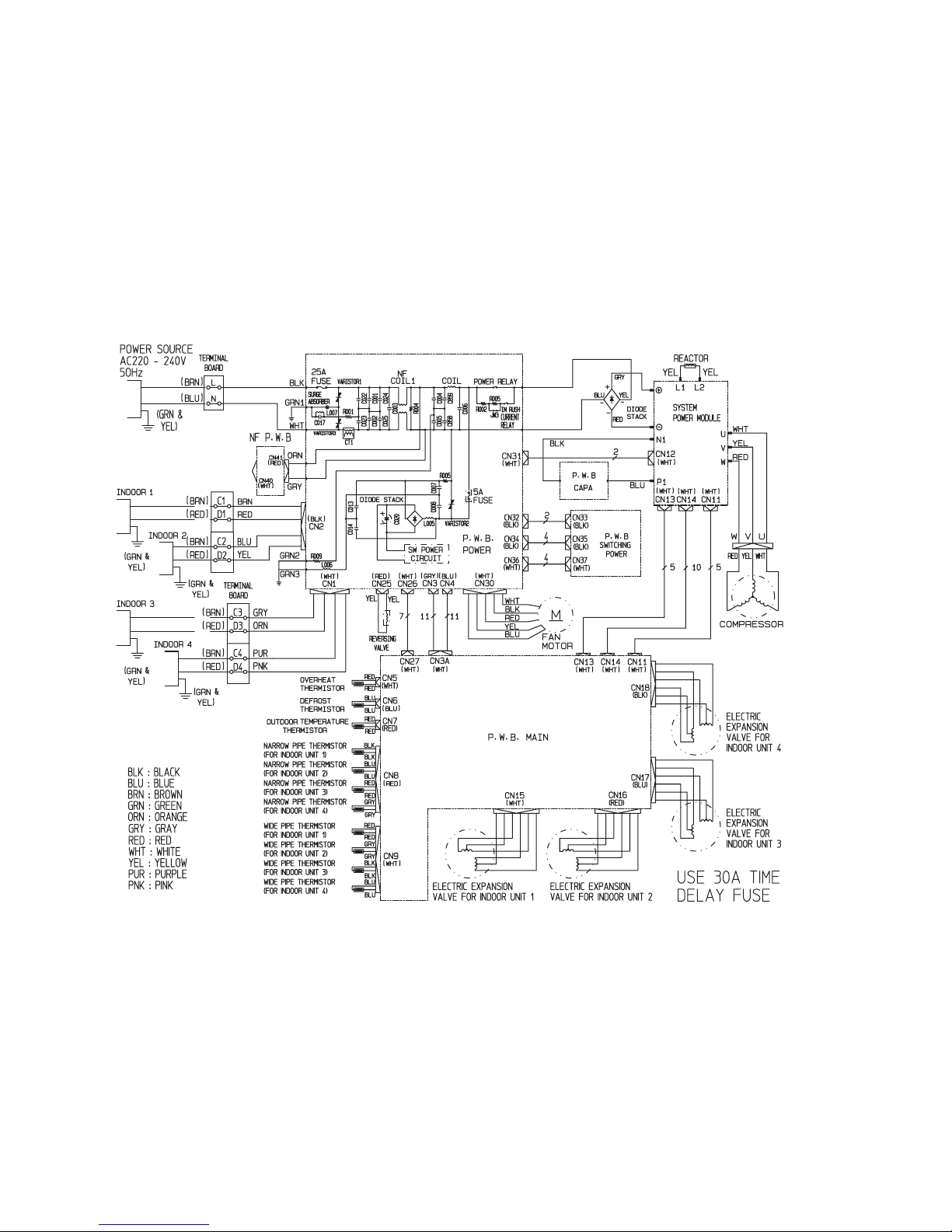
CIRCUIT DIAGRAM
MODEL RAM-71QH5
– 25 –
– 27 –
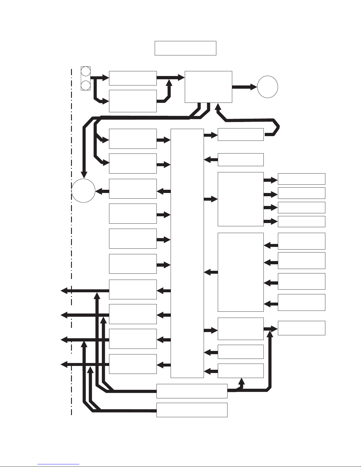
BLOCK DIAGRAM
MODEL RAM-71QH5
Outdoor micro computer (AX-6V)
Magnetic relay
Inrush current
protection relay
M
L
N
Rotor position
detector
Overload current
detector
SPM driver
Overheat
thermistor
Defrost
thermistor
Outdoor temp
thermistor
Indoor/Outdoor
Interface 1
Indoor/Outdoor
Interface 2
Indoor/Outdoor
Interface 3
Switching power supply 3
Switching power supply 2
Reset circuit
Indoor/Outdoor
Interface 4
Clock circuit
Multiplexer
Expansion valve
thermistor 3
Expansion valve
thermistor 1
Expansion valve
thermistor 2
Expansion valve
thermistor 4
Expansion valve 1
Expansion valve 2
Expansion valve 3
Expansion valve
drive circuit
Expansion valve 4
Reversing valve
drive circuit
Reversing valve
EEPROM
Fan motor
drive circuit
M
compressor
fan motor
Indoor unit 1
Indoor unit 2
Indoor unit 3
C1/D1
C2/D2
C3/D3
Indoor unit 4
C4/D4
Power source
single phase 50Hz, 220-240V
Outdoor Unit
System
Power
Module
 Loading...