

Page 1
RAM-55QH4
RAM-65QH4
NO. 0217E
SPECIFICATIONS AND PARTS ARE SUBJECT TO CHANGE FOR IMPROVEMENT
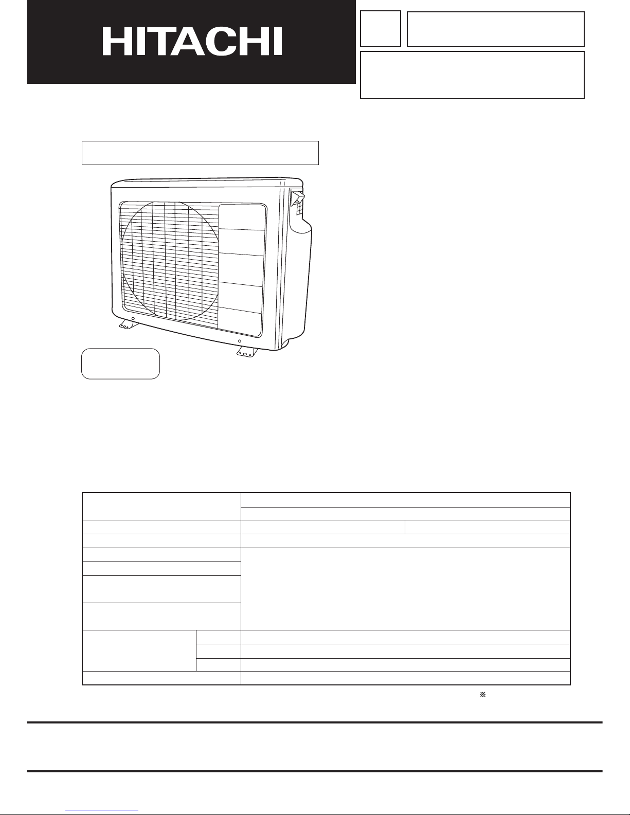
ROOM AIR CONDITIONER
OUTDOOR UNIT
JUNE 2004
Refrigeration & Air-Conditioning Division
SERVICE MANUAL
PM
REFER TO THE FOUNDATION MANUAL
TECHNICAL INFORMATION
FOR SERVICE PERSONNEL ONLY
CONTENTS
SPECIFICATIONS ------------------------------------------------------------------- 5
INSTALLATION ----------------------------------------------------------------------14
CONSTRUCTION AND DIMENSIONAL DIAGRAM ----------------------21
MAIN PARTS COMPONENT --------------------------------------------------- 23
CAPACITY DIAGRAM ------------------------------------------------------------- 25
WIRING DIAGRAM ----------------------------------------------------------------- 33
CIRCUIT DIAGRAM ----------------------------------------------------------------37
BLOCK DIAGRAM ------------------------------------------------------------------ 43
BASIC MODE ------------------------------------------------------------------------ 45
REFRIGERATING CYCLE DIAGRAM ---------------------------------------- 73
DESCRIPTION OF MAIN CIRCUIT OPERATION ------------------------ 77
TROUBLE SHOOTING ---------------------------------------------------------- 108
DISASSEMBLY AND REASSEMBLY --------------------------------------- 115
PARTS LIST AND DIAGRAM ------------------------------------------------- 118
RAM-55QH4
RAM-65QH4
After installation
NOTE:
This manual describes only points that differ from RAF-25,
50NH4, RAD-25, 40QH4 and RAM-70, 80QH4 (TC No.
0757EF), RAK-25, 35, 50NH4 (TC No. 0761EF), RAD-25,
40NH4, RAI-25, 40NH4 (TC No. 0763EF) for items not
described in this manual.
850
650
298
50
(W)
(A)
COOLING CAPACITY
DC INVERTER DUAL SYSTEM MULTI
TYPE
MODEL
POWER SOURCE
TOTAL INPUT
TOTAL AMPERES
SPECIFICATIONS
OUTDOOR UNIT
RAM-55QH4
RAM-65QH4
HEATING CAPACITY
DIMENSIONS (mm)
NET WEIGHT
1ø, 220 - 240V, 50Hz
W
H
D
(kg)
(kW)
(B.T.U.)
REFER TO THE SPECIFICATIONS PAGE
Page 2
– 1 –
SAFETY DURING REPAIR WORK
1. In order to disassemble and repair
the unit in question, be sure to
disconnect the power cord plug
from the power outlet before starting
the work.
2. If it is necessary to replace any parts, they should be replaced with respective genuine parts for the unit, and
the replacement must be effected in correct manner according to the instructions in the Service Manual of
the unit.
If the contacts of electrical parts
are defective, replace the
electrical parts without trying to
repair them.
3. After completion of repairs, the initial state
should be restored.
4. Lead wires should be connected and laid as
in the initial state.
5. Modification of the unit by user himself should
absolutely be prohibited.
6. Tools and measuring instruments for use in repairs or inspection should be accurately calibrated in advance.
7. In installing the unit having been repaired, be careful to prevent the occurence of any accident such as
electrical shock, leak of current, or bodily injury due to the drop of any part.
8. To check the insulation of the unit, measure the insulation resistance between the power cord plug and
grounding terminal of the unit. The insulation resistance should be 1M
or more as measured by a 500V
DC megger.
9. The initial location of installation such as window, floor or the other should be checked for being and safe
enough to support the repaired unit again.
If it is found not so strong and safe, the unit should be installed at the initial location reinforced or at a new
location.
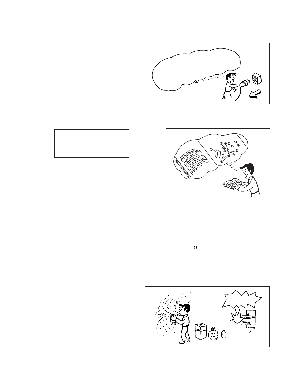
10. Any inflammable thing should never
be placed about the location of
installation.
11. Check the grounding to see whether
it is proper or not, and if it is found
improper, connect the grounding
terminal to the earth.
DANGER
First, I must disconnect
the power cord plug
from the power outlet.
Page 3
– 2 –
WORKING STANDARDS FOR PREVENTING BREAKAGE OF SEMICONDUCTORS
1. Scope
The standards provide for items to be generally observed in carrying and handling semiconductors in relative
manufacturers during maintenance and handling thereof. (They apply the same to handling of abnormal goods
such as rejected goods being returned).
2. Object parts
(1) Micro computer
(2) Integrated circuits (IC)
(3) Field-effect transistors (FET)
(4) P.C. boards or the like on which the parts mentioned in (1) and (2) of this paragraph are equipped.
3. Items to be observed in handling
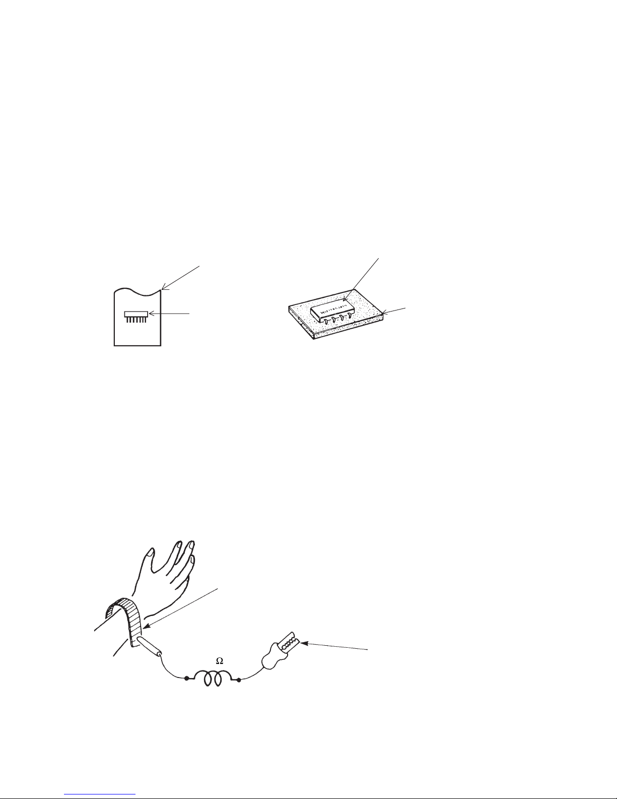
(1) Use a conductive container for carrying and storing of parts. (Even rejected goods should be handled in
the same way).
Fig. 1. Conductive Container
(2) When any part is handled uncovered (in counting, packing and the like), the handling person must always
use himself as a body earth. (Make yourself a body earth by passing one M ohm earth resistance through
a ring or bracelet).
(3) Be careful not to touch the parts with your clothing when you hold a part even if a body earth is being
taken.
(4) Be sure to place a part on a metal plate with grounding.
(5) Be careful not to fail to turn off power when you repair the printed circuit board. At the same time, try
to repair the printed circuit board on a grounded metal plate.
1M
Fig. 2. Body Earth
Body earth
(Elimik conductive band)
Clip for connection with a
grounding wire
IC
A conductive polyvinyl bag
IC
Conductive sponge
Page 4
– 3 –
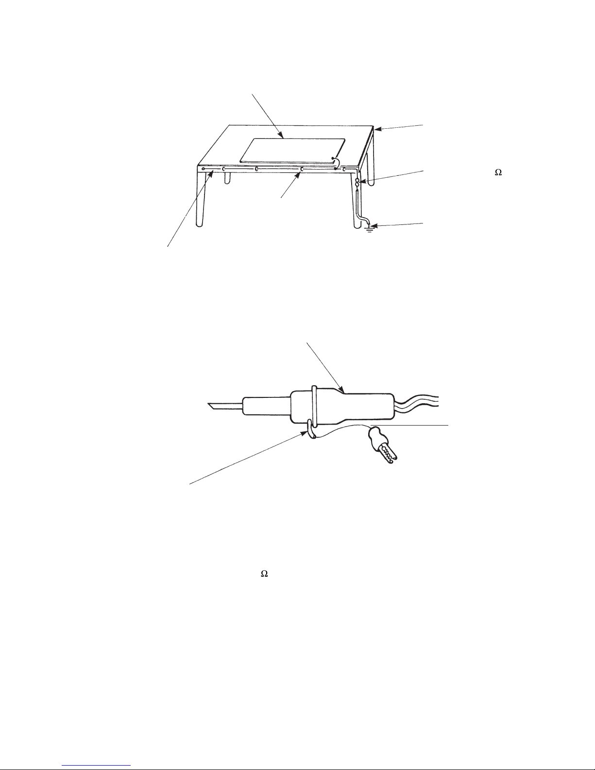
(6) Use a three wire type soldering iron including a grounding wire.
Bare copper wire (for body earth)
Working
table
Resistor of 1 M
(1/2W)
Earth wire
Fig. 3. Grounding of the working table
2
Screw stop at the screwed
part using a rag plate
Soldering iron
Grounding
wire
Fig. 4. Grounding a soldering iron
Use a high insulation mode (100V, 10M
or higher) when ordinary iron is to be used.
(7) In checking circuits for maintenance, inspection or some others, be careful not to have the test probes of the
measuring instrument shortcircuit a load circuit or the like.
Metal plate (of aluminium, stainless steel, etc.)
Staple
Page 5

– 4 –
1. In quiet operation or stopping the running, slight flowing noise of refrigerant in the refrigerating cycle is
heard occasionally, but this noise is not abnormal for the operation.
2. When it thunders near by, it is recommend to stop the operation and to disconnect the power cord plug
from the power outlet for safety.
3. The room air conditioner does not start automatically after recovery of the electric power failure for
preventing fuse blowing. Re-press START/STOP button after 3 minutes from when unit stopped.
4. If the room air conditioner is stopped by adjusting thermostat, or missoperation, and re-start in a moment,
there is occasion that the cooling and heating operation does not start for 3 minutes, it is not abnormal
and this is the result of the operation of IC delay circuit. This IC delay circuit ensures that there is no
danger of blowing fuse or damaging parts even if operation is restarted accidentally.
5. This room air conditioner should not be used at the cooling operation when the outside temperature is
below 10°C (50°F).
6. This room air conditioner (the reverse cycle) should not be used when the outside temperature is below
–15°C (5°F).
If the reverse cycle is used under this condition, the outside heat exchanger is frosted and efficiency falls.
7. When the outside heat exchanger is frosted, the frost is melted by operating the hot gas system, it is not
trouble that at this time fan stops and the vapour may rise from the outside heat exchanger.
!
CAUTION
Page 6

– 5 –
SPECIFICATIONS
MODEL
FAN MOTOR
FAN MOTOR CAPACITOR
FAN MOTOR PROTECTOR
COMPRESSOR
COMPRESSOR MOTOR CAPACITOR
OVERLOAD PROTECTOR
OVERHEAT PROTECTOR
FUSE (for MICROPROCESSOR)
POWER RELAY
POWER SWITCH
TEMPORARY SWITCH
SERVICE SWITCH
TRANSFORMER
VARISTOR
NOISE SUPPRESSOR
THERMOSTAT
REMOTE CONTROL SWITCH (LIQUID CRYSTAL)
40 W
NO
NO
NO
YES
YES
5.0A
G4A
NO
NO
YES
NO
450NR
YES
YES(IC)
NO
1650g
WITHOUT REFRIGERANT BECAUSE
COUPLING IS FLARE TYPE.
UNIT
PIPES
REFRIGERANT CHARGING
VOLUME
(Refrigerant 410A)
RAM-55QH4 RAM-65QH4
JU1013D2
MAX. 35m MAX. 45m
RAM-65QH4
In case the pipe length is more than 35m, add refrigerant R410 at 20gram per every meter exceeds.
RAM-55QH4
Additional charge of refrigerant is not required.
Page 7
– 6 –
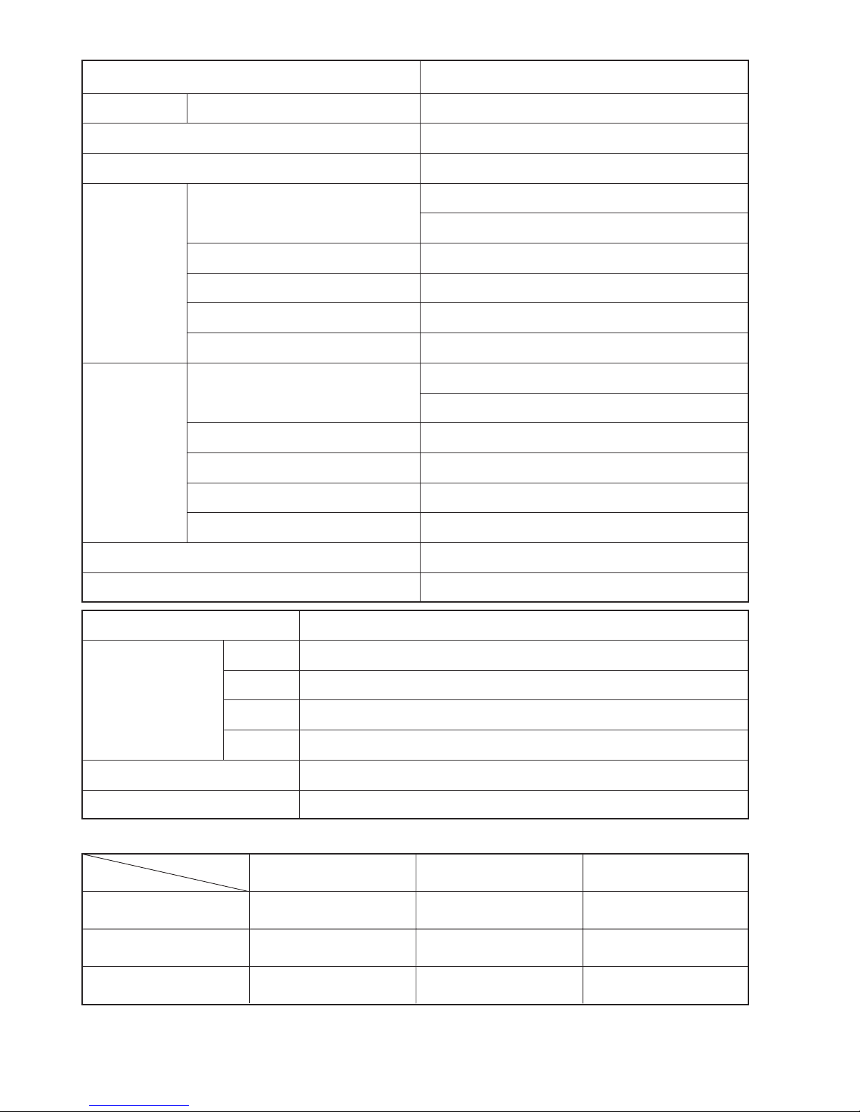
SPECIFICATIONS FOR INDOOR UNITS COMBINATION
OPERATION SCOPE
TYPE
DC INVERTER DUAL SYSTEM MULTI COOLING AND HEATING
MODEL OUTDOOR UNIT
PHESE/VOLTAGE/FREQUENCY
CIRCUIT AMPERES TO CONNECT (A)
COOLING
(TWO UNITS)
CAPACITY (kW)
(B.T.U./h)
TOTAL INPUT (W)
EER (B.T.U./hW)
TOTAL AMPERES (A)
POWER FACTOR (%)
HEATING
(TWO UNITS)
CAPACITY (kW)
(B.T.U./h)
TOTAL INPUT (W)
EER (B.T.U./hW)
TOTAL AMPERES (A)
POWER FACTOR (%)
MAXIMUM LENGTH OF PIPING
STANDARD
RAM-55QH4
1ø, 220 - 240V, 50Hz
16
5.40 (1.50 - 5.90)
18,430 (5,120 - 20,130)
1,795 (200 - 1,980)
10.27
8.3 - 7.6
99
7.20 (1.50 - 7.20)
24,560 (5,120 - 24,560)
2,100 (200 - 2,100)
11.70
9.6 - 8.8
99
MAX. 35m (TWO UNIT TOTAL)
CE (EMC&LVD)
RAM-55QH4
MODEL
W
PACKING
(mm)
H
D
cu.ft.
1,008
698
394
9.79
53
GROSS WEIGHT (kg)
6.35D/9.52DX2
FLARENUTSIZE (SMALL/LARGE)
INDOOR SUCTION
TEMPERATURE (˚C)
COOLING OPERATION SCOPE
OUTDOOR SUCTION
TEMPERATURE (˚C)
INDOOR SUCTION
HUMIDITY (%)
DEHUMIDIFYING
OPERATION
HEATING OPERATION
SCOPE
16 - 32 22 - 41 BELOW 80
16 - 32 22 - 42 BELOW 80
BELOW 27 –15 - 23 —
Page 8
– 7 –
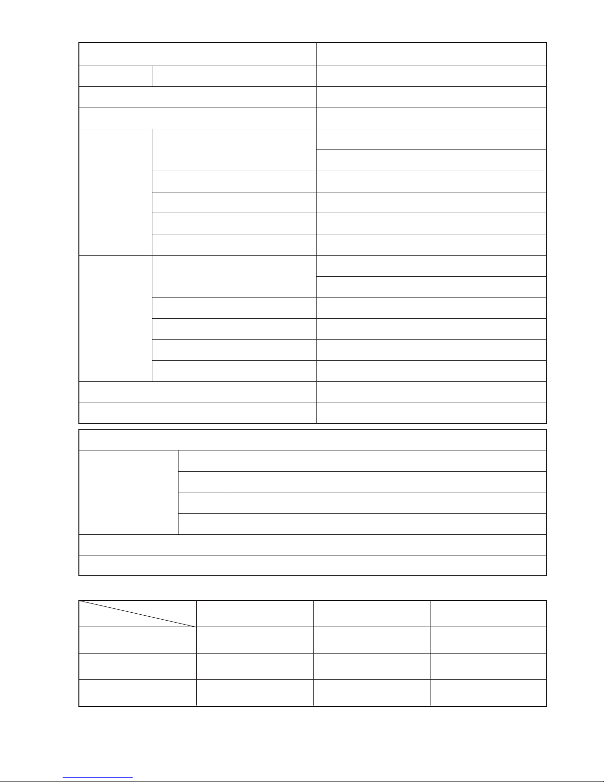
SPECIFICATIONS FOR INDOOR UNITS COMBINATION
OPERATION SCOPE
TYPE
DC INVERTER TRIPLE SYSTEM MULTI COOLING AND HEATING
MODEL OUTDOOR UNIT
PHESE/VOLTAGE/FREQUENCY
CIRCUIT AMPERES TO CONNECT (A)
COOLING
(THREE UNITS)
CAPACITY (kW)
(B.T.U./h)
TOTAL INPUT (W)
EER (B.T.U./hW)
TOTAL AMPERES (A)
POWER FACTOR (%)
HEATING
(THREE UNITS)
CAPACITY (kW)
(B.T.U./h)
TOTAL INPUT (W)
EER (B.T.U./hW)
TOTAL AMPERES (A)
POWER FACTOR (%)
MAXIMUM LENGTH OF PIPING
STANDARD
RAM-65QH4
1ø, 220 - 240V, 50Hz
16
6.30 (1.50 - 6.60)
21,510 (5,120 - 22,530)
2,095 (200 - 2,200)
10.26
9.7 - 8.9
99
7.20 (1.50 - 7.20)
24,560 (5,120 - 24,560)
1,900 (200 - 2,100)
12.93
8.8 - 8.0
99
MAX. 45m (THREE UNIT TOTAL)
CE (EMC&LVD)
RAM-65QH4
MODEL
W
PACKING
(mm)
H
D
cu.ft.
1,008
698
394
9.79
55
GROSS WEIGHT (kg)
6.35D/9.52DX3
FLARENUTSIZE (SMALL/LARGE)
INDOOR SUCTION
TEMPERATURE (˚C)
COOLING OPERATION SCOPE
OUTDOOR SUCTION
TEMPERATURE (˚C)
INDOOR SUCTION
HUMIDITY (%)
DEHUMIDIFYING
OPERATION
HEATING OPERATION
SCOPE
16 - 32 22 - 41 BELOW 80
16 - 32 22 - 42 BELOW 80
BELOW 27 –15 - 23 —
Page 9
– 8 –
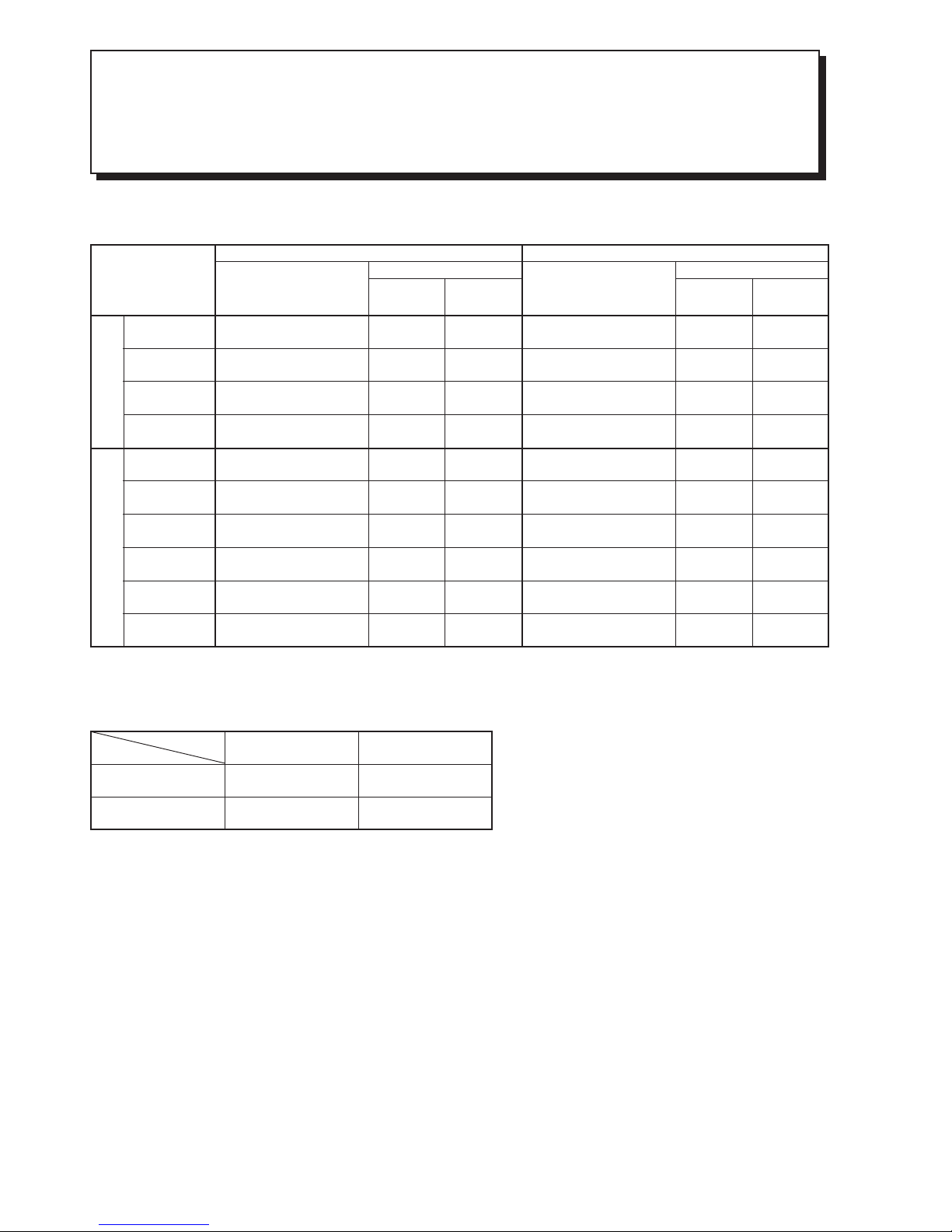
DUAL SYSTEM MULTI R.A.C.
RAM-55QH4
COOL / HEAT CAPACITY SPEC. FOR INDOOR UNITS
COMBINATIONS TO BE ABLE TO OPERATE SIMULTANEOUSLY
Whichever indoor units are installed, cooling and heating capacity depends on how many and which indoor units
are operating at that time.
RATING CONDITON (DRY BLUB / WET BULB)
COOLING
HEATING
INDOOR OUTDOOR
27 / 19 ˚C
20 / –˚C
35 / –˚C
7 / 6˚C
POSSIBLE
COMBINATIONS
TO OPERATE
CAPACITY RATING
(kW)
(RANGE)
POWER
CONSUMPTION
(W)
AMPERE
(A)
220-240V
OUTDOOR UNIT
C O O L I N G
CAPACITY RATING
(kW)
(RANGE)
POWER
CONSUMPTION
(W)
AMPERE
(A)
220-240V
OUTDOOR UNIT
H E A T I N G
ONE UNIT
TWO UNIT
2.5
3.5
4.0
5.0
2.5+2.5
2.5+3.5
2.5+4.0
3.5+3.5
2.5+5.0
3.5+4.0
2.50
(1.00-2.80)
3.50
(1.00-3.90)
4.00
(1.00-4.50)
5.00
(1.00-5.60)
2.50+2.50
(1.50-5.60)
2.17+3.03
(1.50-5.70)
2.10+3.30
(1.50-5.90)
2.70+2.70
(1.50-5.90)
1.80+3.60
(1.50-5.90)
2.50+2.90
(1.50-5.90)
780
(200-980)
1160
(200-1280)
1330
(200-1480)
1780
(200-1960)
1650
(200-1820)
1730
(200-1900)
1795
(200-1980)
1795
(200-1980)
1795
(200-1980)
1795
(200-1980)
3.6-3.3
5.3-4.9
6.1-5.6
8.2-7.5
7.6-6.9
7.9-7.3
8.2-7.6
8.2-7.6
8.2-7.6
8.2-7.6
3.90
(1.10-4.70)
4.80
(1.10-5.80)
6.00
(1.10-6.80)
6.50
(1.10-7.20)
3.40+3.40
(1.50-7.20)
3.15+3.85
(1.50-7.20)
2.85+4.35
(1.50-7.20)
3.60+3.60
(1.50-7.20)
2.70+4.50
(1.50-7.20)
3.20+4.00
(1.50-7.20)
1145
(200-1380)
1550
(200-1870)
2150
(200-2440)
2400
(200-2660)
2015
(200-2110)
2070
(200-2110)
2110
(200-2110)
2110
(200-2110)
2110
(200-2110)
2110
(200-2110)
5.3-4.8
7.1-6.5
9.9-9.0
11.0-10.1
9.3-8.5
9.5-8.7
9.7-8.9
9.7-8.9
9.7-8.9
9.7-8.9
ONE UNIT : The values indicated are only for one unit opration when two indoor units are connected.
Page 10
– 9 –
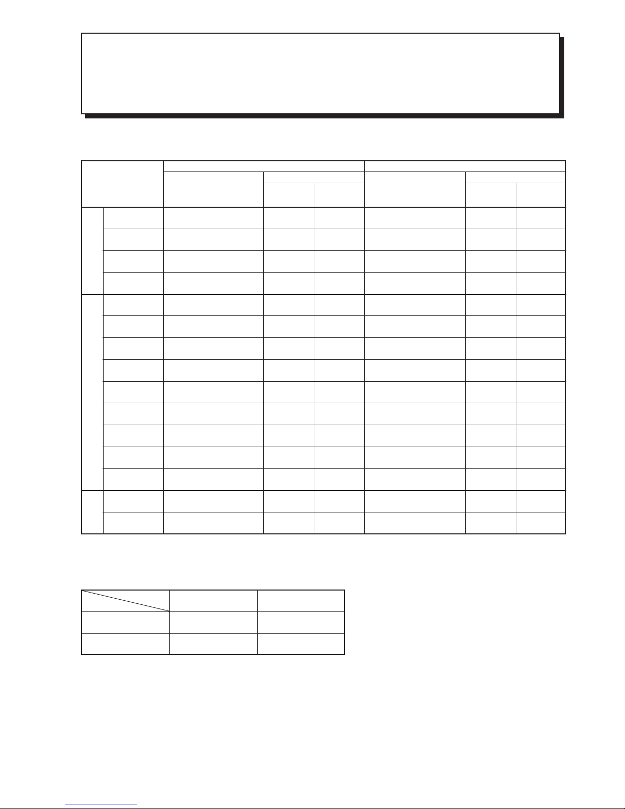
TRIPLE SYSTEM MULTI R.A.C.
RAM-65QH4
COOL / HEAT CAPACITY SPEC. FOR INDOOR UNITS
COMBINATIONS TO BE ABLE TO OPERATE SIMULTANEOUSLY
Whichever indoor units are installed, cooling and heating capacity depends on how many and which indoor units
are operating at that time.
RATING CONDITON (DRY BLUB / WET BULB)
COOLING
HEATING
INDOOR OUTDOOR
27 / 19 ˚C
20 / –˚C
35 / –˚C
7 / 6˚C
POSSIBLE
COMBINATIONS
TO OPERATE
CAPACITY RATING
(kW)
(RANGE)
POWER
CONSUMPTION
(W)
AMPERE
(A)
220-240V
OUTDOOR UNIT
C O O L I N G
CAPACITY RATING
(kW)
(RANGE)
POWER
CONSUMPTION
(W)
AMPERE
(A)
220-240V
OUTDOOR UNIT
H E A T I N G
ONE UNIT
TWO UNIT
THREE UNIT
2.5
3.5
4.0
5.0
2.5+2.5
2.5+3.5
2.5+4.0
3.5+3.5
2.5+5.0
3.5+4.0
4.0+4.0
3.5+5.0
4.0+5.0
2.5+2.5+2.5
2.5+2.5+3.5
2.50
(1.00-2.80)
3.50
(1.00-3.90)
4.00
(1.00-4.50)
5.00
(1.00-5.60)
2.50+2.50
(1.50-5.60)
2.17+3.03
(1.50-5.70)
2.10+3.30
(1.50-5.90)
2.70+2.70
(1.50-5.90)
1.80+3.60
(1.50-5.90)
2.50+2.90
(1.50-5.90)
3.00+3.00
(1.50-6.60)
2.50+3.50
(1.50-6.60)
2.67+3.33
(1.50-6.60)
2.10+2.10+2.10
(1.50-6.60)
1.85+1.85+2.60
(1.50-6.60)
780
(200-980)
1160
(200-1280)
1330
(200-1480)
1780
(200-1960)
1650
(200-1820)
1730
(200-1900)
1795
(200-1980)
1795
(200-1980)
1795
(200-1980)
1795
(200-1980)
1995
(200-2200)
1995
(200-2200)
1995
(200-2200)
2095
(200-2200)
2095
(200-2200)
3.6-3.3
5.3-4.9
6.1-5.6
8.2-7.5
7.6-6.9
7.9-7.3
8.2-7.6
8.2-7.6
8.2-7.6
8.2-7.6
9.2-8.4
9.2-8.4
9.2-8.4
9.6-8.8
9.6-8.8
3.90
(1.10-4.70)
4.80
(1.10-5.80)
6.00
(1.10-6.80)
6.50
(1.10-7.20)
3.40+3.40
(1.50-7.20)
3.15+3.85
(1.50-7.20)
2.85+4.35
(1.50-7.20)
3.60+3.60
(1.50-7.20)
2.70+4.50
(1.50-7.20)
3.20+4.00
(1.50-7.20)
3.60+3.60
(1.50-7.20)
3.05+4.15
(1.50-7.20)
3.45+3.75
(1.50-7.20)
2.40+2.40+2.40
(1.50-7.20)
2.23+2.23+2.74
(1.50-7.20)
1145
(200-1380)
1550
(200-1870)
2150
(200-2440)
2400
(200-2660)
2015
(200-2110)
2070
(200-2110)
2110
(200-2110)
2110
(200-2110)
2110
(200-2110)
2110
(200-2110)
2110
(200-2100)
2110
(200-2100)
2110
(200-2110)
1900
(200-2110)
1900
(200-2110)
5.3-4.8
7.1-6.5
9.9-9.0
11.0-10.1
9.3-8.5
9.5-8.7
9.7-8.9
9.7-8.9
9.7-8.9
9.7-8.9
9.7-8.9
9.7-8.9
9.7-8.9
8.7-8.0
8.7-8.0
ONE UNIT : The values indicated are only for one unit opration when two indoor units are connected.
Page 11

– 10 –
DUAL SYSTEM MULTI R.A.C.
RAM-55QH4
INDOOR UNITS COMBINATIONS TO BE ABLE TO INSTALL
Two indoor units can be installed with one outdoor unit.
And total nominal cooling capacity should not be more than 7.5kW
INDOOR UNIT
MODEL
NOMINAL
COOLING
CAPACITY
(kW)
CAPACITY (kW)
at one unit operation
SUITABLE ROOM SIZE (m
2
)
at one unit operation
COOLING HEATING COOLING HEATING
RAK-25NH4
RAF-25NH4
RAD-25NH4
RAI-25NH4
RAK-35NH4
RAD-40NH4
RAI-40NH4
RAK-50NH4
RAF-50NH4
2.5
2.5
2.5
2.5
3.5
4.0
4.0
5.0
5.0
1.00 - 2.80
1.00 - 2.80
1.00 - 2.80
1.00 - 2.80
1.00 - 3.90
1.00 - 4.50
1.00 - 4.50
1.00 - 5.60
1.00 - 5.60
1.10 - 4.70
1.10 - 4.70
1.10 - 4.70
1.10 - 4.70
1.10 - 5.80
1.10 - 6.80
1.10 - 6.80
1.10 - 7.20
1.10 - 7.20
11 - 17
11 - 17
11 - 17
11 - 17
16 - 24
18 - 28
18 - 28
23 - 34
23 - 34
14 - 18
14 - 18
14 - 18
14 - 18
17 - 22
22 - 27
22 - 27
23 - 29
23 - 29
Be sure to connect two indoor units to this outdoor unit. If not, condensed water may drop, resulting in trouble.
Page 12

– 11 –
TRIPLE SYSTEM MULTI R.A.C.
RAM-65QH4
INDOOR UNITS COMBINATIONS TO BE ABLE TO INSTALL
Two or three indoor units can be installed with one outdoor unit.
And total nominal cooling capacity should not be more than 9.0kW
INDOOR UNIT
MODEL
NOMINAL
COOLING
CAPACITY
(kW)
CAPACITY (kW)
at one unit operation
SUITABLE ROOM SIZE (m
2
)
at one unit operation
COOLING HEATING COOLING HEATING
RAK-25NH4
RAF-25NH4
RAD-25NH4
RAI-25NH4
RAK-35NH4
RAD-40NH4
RAI-40NH4
RAK-50NH4
RAF-50NH4
2.5
2.5
2.5
2.5
3.5
4.0
4.0
5.0
5.0
1.00 - 2.80
1.00 - 2.80
1.00 - 2.80
1.00 - 2.80
1.00 - 3.90
1.00 - 4.50
1.00 - 4.50
1.00 - 5.60
1.00 - 5.60
1.10 - 4.70
1.10 - 4.70
1.10 - 4.70
1.10 - 4.70
1.10 - 5.80
1.10 - 6.80
1.10 - 6.80
1.10 - 7.20
1.10 - 7.20
11 - 17
11 - 17
11 - 17
11 - 17
16 - 24
18 - 28
18 - 28
23 - 34
23 - 34
14 - 18
14 - 18
14 - 18
14 - 18
17 - 22
22 - 27
22 - 27
23 - 29
23 - 29
Be sure to connect two or three indoor units to this outdoor unit. If not, condensed water may drop, resulting in
trouble.
Page 13
– 12 –
DUAL SYSTEM MULTI R.A.C.
RAM-55QH4
CONNECTING POSISION TO BE ABLE TO INSTALL
POSSIBLE COMBINATIONS
TO INSTALL
(kW)
CONNECTING POSITION ON
OUTDOOR UNIT
(VALVE DIAMETER)
(mm)
No.1 No.2
2.5, 3.5, 4.0, 5.0 means indoor units cooling capacity class.
(1) Marking
: needs flare adapter (9.52 12.7D): Part No. TA261D-4 001
(2) Suitable room size is determined based on the conditions below:
• Climate is in the temperate zone like Tokyo, Japan.
• For usual residential use.
• Smaller figure is for light construction which means light thermally sealed.
• Larger figure is for heavy constructions, which means well thermally sealed.
SUITABLE ROOM SIZE
TO INSTALL
(m
2
)
6.35/9.52D 6.35/9.52D
TWO UNITS
2.5+2.5
2.5+3.5
2.5+4.0
3.5+3.5
2.5+5.0
3.5+4.0
(12-15) + (12-15)
(11-14) + (14-18)
(10-13) + (15-19)
(13-16) + (13-16)
(10-12) + (18-20)
(12-14) + (14-18)
2.5
2.5
2.5
3.5
2.5
3.5
2.5
3.5
4.0
3.5
5.0
4.0
Page 14
– 13 –
TRIPLE SYSTEM MULTI R.A.C.
RAM-65QH4
CONNECTING POSISION TO BE ABLE TO INSTALL
POSSIBLE COMBINATIONS
TO INSTALL
(kW)
CONNECTING POSITION ON
OUTDOOR UNIT
(VALVE DIAMETER)
(mm)
No.1 No.2
2.5, 3.5, 4.0, 5.0 means indoor units cooling capacity class.
(1) Marking
: needs flare adapter (9.52 12.7D): Part No. TA261D-4 001
(2) Suitable room size is determined based on the conditions below:
• Climate is in the temperate zone like Tokyo, Japan.
• For usual residential use.
• Smaller figure is for light construction which means light thermally sealed.
• Larger figure is for heavy constructions, which means well thermally sealed.
SUITABLE ROOM SIZE
TO INSTALL
(m
2
)
No.3
6.35/9.52D 6.35/9.52D 6.35/9.52D
TWO UNITS
THREE UNITS
2.5+2.5
2.5+3.5
2.5+4.0
3.5+3.5
2.5+5.0
3.5+4.0
4.0+4.0
3.5+5.0
4.0+5.0
2.5+2.5+2.5
2.5+2.5+3.5
(12-15) + (12-15)
(11-14) + (14-18)
(10-13) + (15-19)
(13-16) + (13-16)
(10-12) + (18-20)
(12-14) + (14-18)
(13-16) + (13-16)
(11-14) + (16-18)
(12-15) + (16-17)
(10-11) + (10-11) + (10-11)
(8-10) + (8-10) + (12-12)
2.5
2.5
2.5
3.5
2.5
3.5
4.0
3.5
4.0
2.5
2.5
2.5
3.5
4.0
3.5
5.0
4.0
4.0
5.0
5.0
2.5
2.5
2.5
3.5
Page 15
– 14 –
Indoor unit 1
Outdoor unit
Outdoor unit
Maximum 5m
Maximum ±10m
Indoor unit
Indoor unit
Indoor unit 2
INSTALLATION
PIPE LENGTH
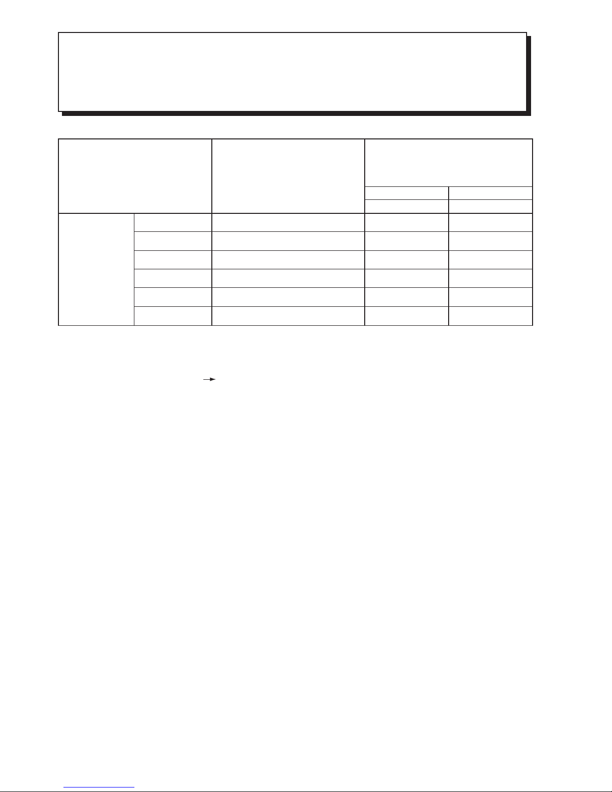
(1) Total 35m maximum pipe length.
(2) Pipe length for one indoor unit : maximum 25m.
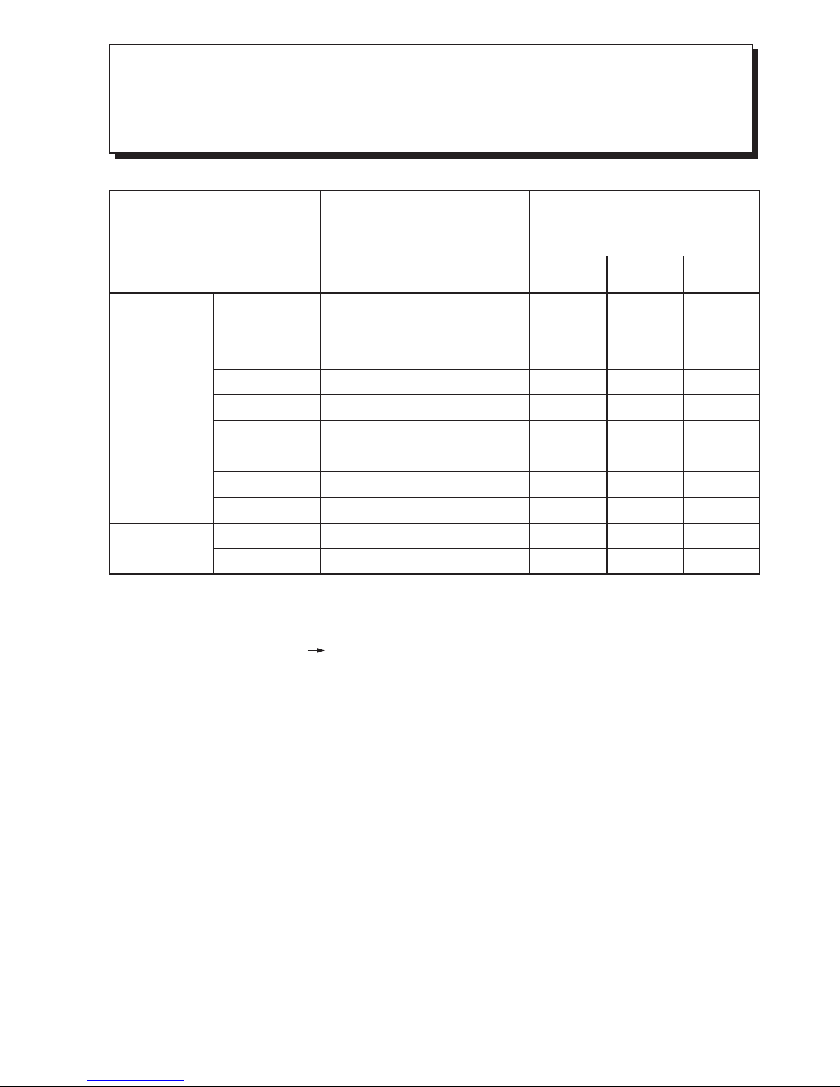
HIGHT DIFFERENCE
(1) Hight : maximum ± 10m
(2) Hight difference between each indoor unit ≤ 5m.
L
1
L
2
To the outdoor unit, up to two indoor units can be connected until the total value of
capacity from 5.0kW to 7.50kW.
Make sure to connect to two indoor units.
Page 16
– 15 –
Indoor unit 1
Outdoor unit
Outdoor unit
Maximum 5m
Maximum ±10m
Indoor unit
Indoor unit
Indoor unit
Indoor unit 2 Indoor unit 3
INSTALLATION
PIPE LENGTH
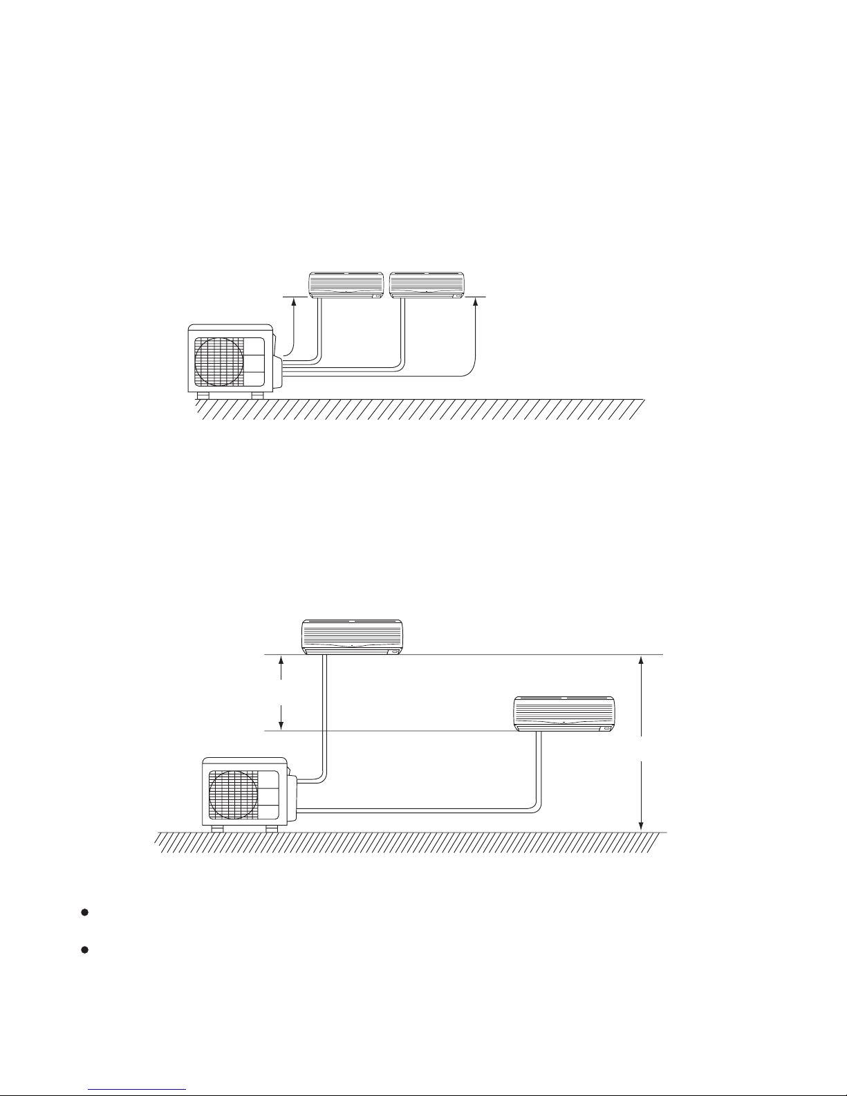
(1) Total 45m maximum pipe length.
(2) Pipe length for one indoor unit : maximum 25m.
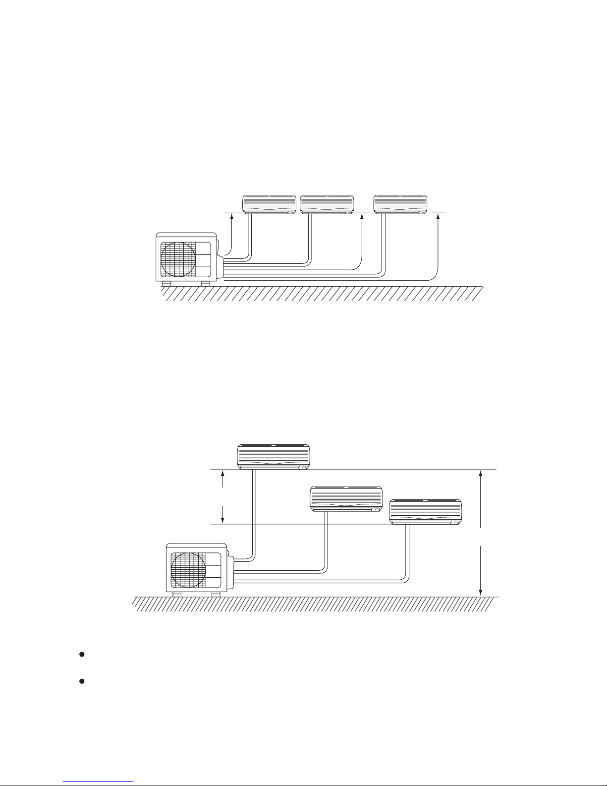
HIGHT DIFFERENCE
(1) Hight : maximum ± 10m
(2) Hight difference between each indoor unit ≤ 5m.
L
1
L
2
L
3
To the outdoor unit, up to three indoor units can be connected until the total value of
capacity from 5.0kW to 9.0kW.
Make sure to connect to two or three indoor units.
Page 17
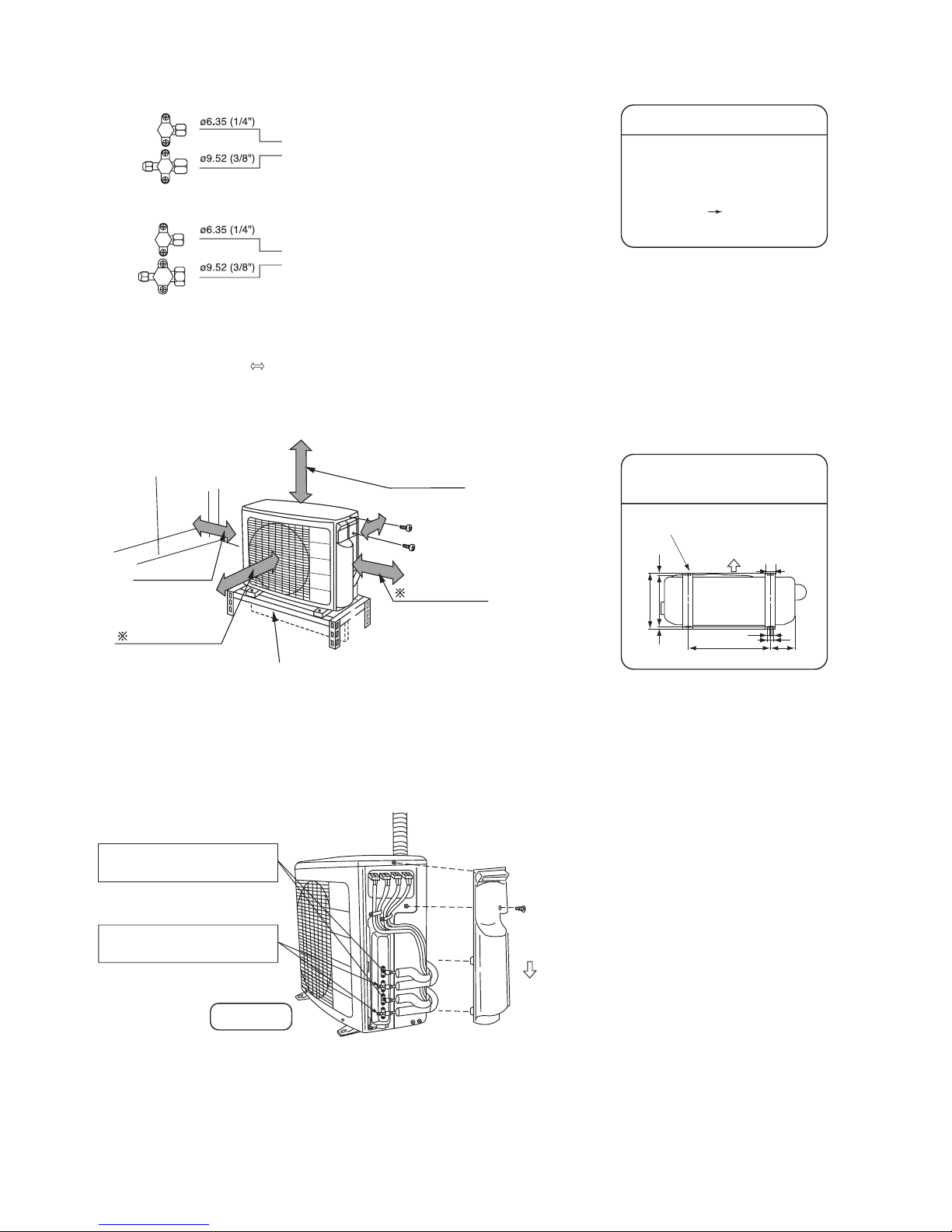
– 16 –
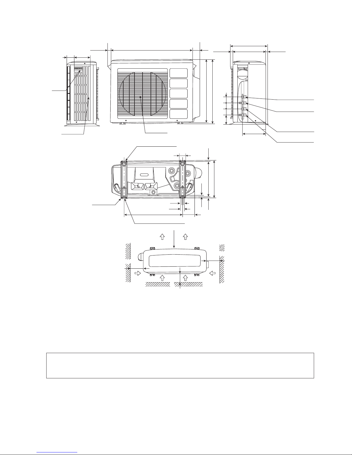
Outdoor unit pipe connection port
One unit of 2.5kW, 3.5kW or 4.0kW
One unit of 2.5kW, 3.5kW, 4.0kW or 5.0kW
(5kW unit: Optional flare adaptor for piping is necessary)
Indoor unit 2 Indoor unit 1
Dimension of Mounting Stand of
the Outdoor Unit
(Unit: mm)
Air blow
Mounting stand
Flare adaptor for piping
•ø9.52 (3/8") ø12.7 (1/2")
parts number TA261D-4 001
The flare adaptor for piping is
required depending on combination
of indoor units.
• Remove the side cover.
• For installation, refer as shown below.
• Install the unit in a stable place to minimize vibrationor noise.
Connecting the pipe
• After arranging the cord and pipes, secure them inplace.
Small diameter side service valve
Tightening torque:
13.7-18.6 N • m {140-190 kgf • cm}
• Hold the handle of the side cover. Slide down and takeoff
the corner hook, then pull. Reverse these stepswhen
installing.
Please face this side (suction side) of the unit to the wall.
Please remove side plate when connecting the piping
and connecting cord.
Slide lower
• The space indicated with a mark is required to guarantee the air conditioner's performance. Install the airconditioner in a
place big enough to provide ample space for servicing and repairs later on.
Heating efficiency will be increased if the ventilation below the outdoor unit is minimized.
507
10 (10)
320
340
198
12
37
57
above 700mm
above 200mm
(
)
above 100mm
above 100mm
Above 50mm when installed on the
ceiling of balcony.
Large diameter side service valve
Tightening torque:
34.3-44.1 N • m {350-450 kgf • cm}
RAM-55QH4
MODEL: RAM-55QH4
Page 18
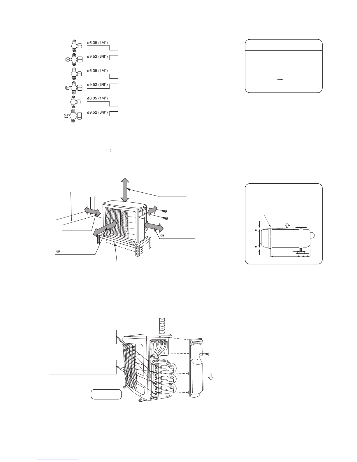
– 17 –
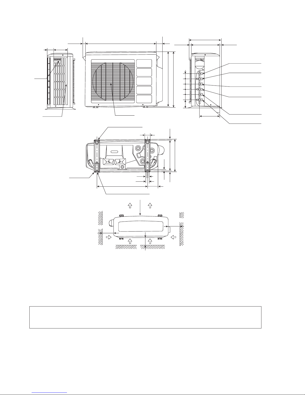
Outdoor unit pipe connection port
One unit of 2.5kW, 3.5kW or 4.0kW
One unit of 2.5kW, 3.5kW, 4.0kW or 5.0kW
One unit of 2.5kW, 3.5kW, 4.0kW or 5.0kW
(5kW unit: Optional flare adaptor for piping is necessary)
Indoor unit 3 Indoor unit 2 Indoor unit 1
Dimension of Mounting Stand of
the Outdoor Unit
(Unit: mm)
Air blow
Mounting stand
Flare adaptor for piping
•ø9.52 (3/8") ø12.7 (1/2")
parts number TA261D-4 001
The flare adaptor for piping is
required depending on combination
of indoor units.
• Remove the side cover.
• For installation, refer as shown below.
• Install the unit in a stable place to minimize vibrationor noise.
Connecting the pipe
• After arranging the cord and pipes, secure them inplace.
Small diameter side service valve
Tightening torque:
13.7-18.6 N • m {140-190 kgf • cm}
• Hold the handle of the side cover. Slide down and takeoff
the corner hook, then pull. Reverse these stepswhen
installing.
Please face this side (suction side) of the unit to the wall.
Please remove side plate when connecting the piping
and connecting cord.
Slide lower
• The space indicated with a mark is required to guarantee the air conditioner's performance. Install the airconditioner in a
place big enough to provide ample space for servicing and repairs later on.
Heating efficiency will be increased if the ventilation below the outdoor unit is minimized.
507
10 (10)
320
340
198
12
37
57
above 700mm
above 200mm
(
)
above 100mm
above 100mm
Above 50mm when installed on the
ceiling of balcony.
Large diameter side service valve
Tightening torque:
34.3-44.1 N • m {350-450 kgf • cm}
RAM-65QH4
MODEL: RAM-65QH4
Page 19
– 18 –
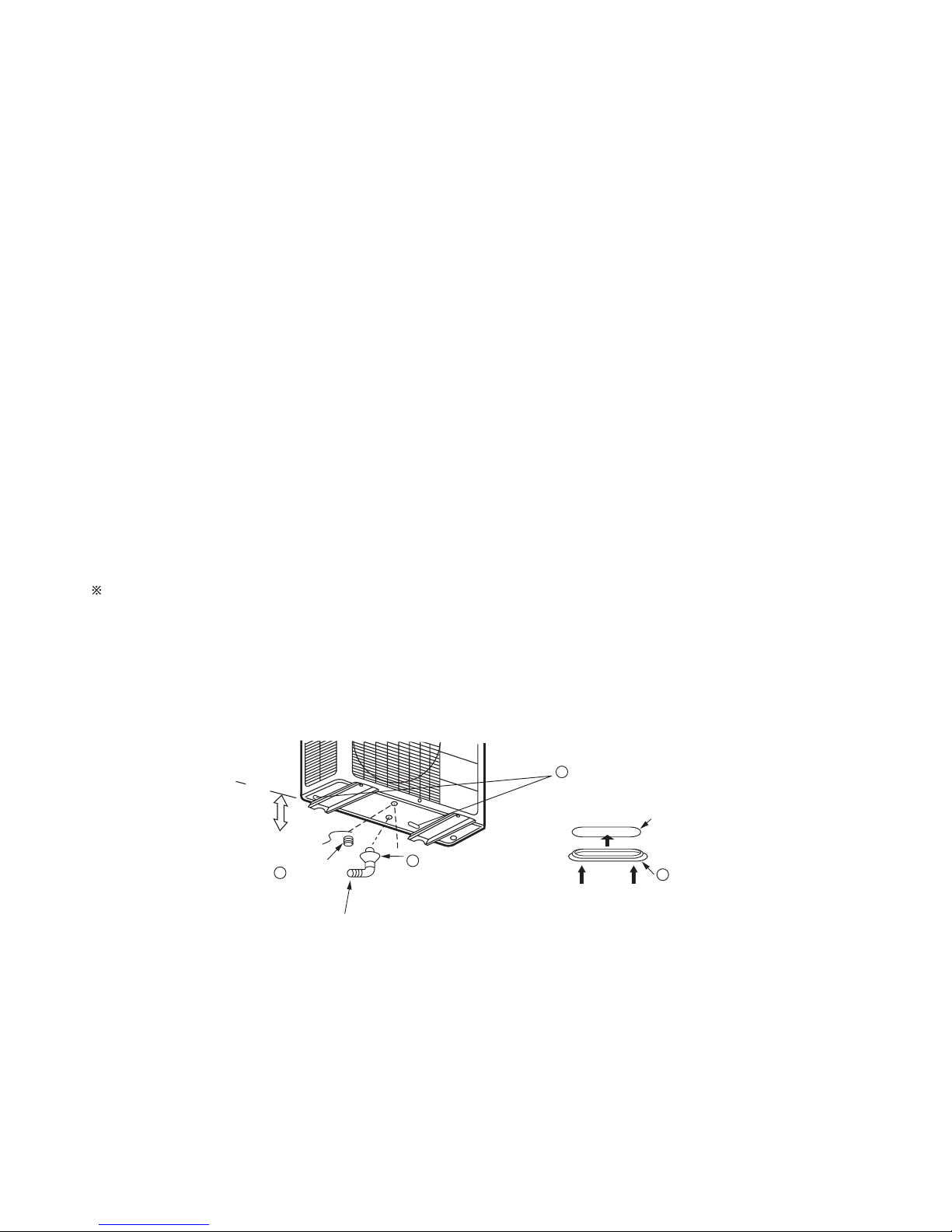
Above 100mm
Drain hole
Bushing
Outer diameter above 16mm
b
•
•
•
•
Condensed water disposal of outdoor unit
When Using and Installing in Cold Areas
There is holes on the base of outdoor unit for condensed water to exhaust.
To lead condensed water to the drain hole, place the outdoor unit on the mounting stand (optional) or on blocks to raise its
level more than 100mm from the ground surface. Connect the drain pipe as shown in the figure. Cover two other water
drain holes with the bushings included. (To insall a bushing, push in both ends of the bushing so that it aligns with the drain
hole.)
When connecting the drain pipe, make sure that the bushing does not lift off or deviate from the base.
1.
Remove flare nut from service valve.
4.
Perform air purge and gas leak inspection.
2.
Apply refrigerant oil to flare nut sections of servicevalve and pipings.
5.
Wrap the provided insulating material around sidepiping using vinyl tape.
3.
Match center of piping to large diameter side service valve and tank assembly, and tighten flarenut first by hand,
then securely tighten using torque wrench.
Install the outdoor unit on a stable, flat surface and check to see that the condensed water drains.
For more details, refer to the Installation Manual for Cold Areas.
When the air conditioner is used in low temperature and in snowy conditions, water from the heat exchanger may freeze
on the base surface to cause poor drainage. When using the air conditioner in such areas, do not install the bushings. Keep a
minimum of 250mm between the drain hole and the ground. When using the drain pipe, consult your sales agent.
Bushingb
Bushingb
Drain pipe
Drain hole
Push Push
a
Page 20
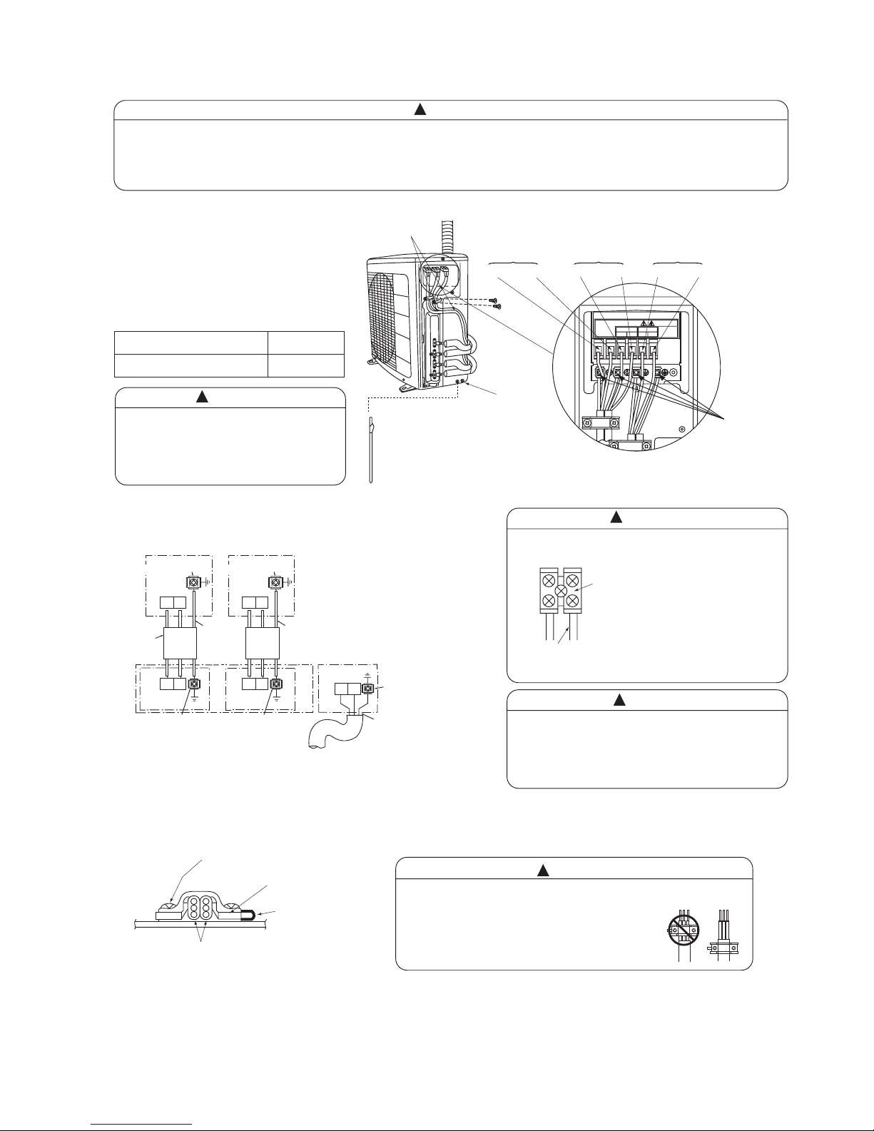
– 19 –
Outdoor Unit
Wiring pattern
Indoor Unit
Fig. 1
Power cord
Screw
Insulating plate
Cord band
Connecting cord
CD
C1 D1
Indoor unit No. 1
Screw for ground, earth screw
Screw for ground, earth screw
For Indoor unit No. 1
Terminal board
Terminal board
Connecting cord
Ø1.6 or 2.0
Green-andYellow
CD
C2 D2
Indoor unit No. 2
Screw for ground, earth screw
Screw for ground, earth screw
For Indoor unit No. 2
Terminal board
Terminal board
Green-andYellow
LN
Screw for ground,
earth screw
Terminal board
Green-and-Yellow
AC 220V~240V ONLY
LN
INDOOR 1
C1D1C2 D2
INDOOR 2
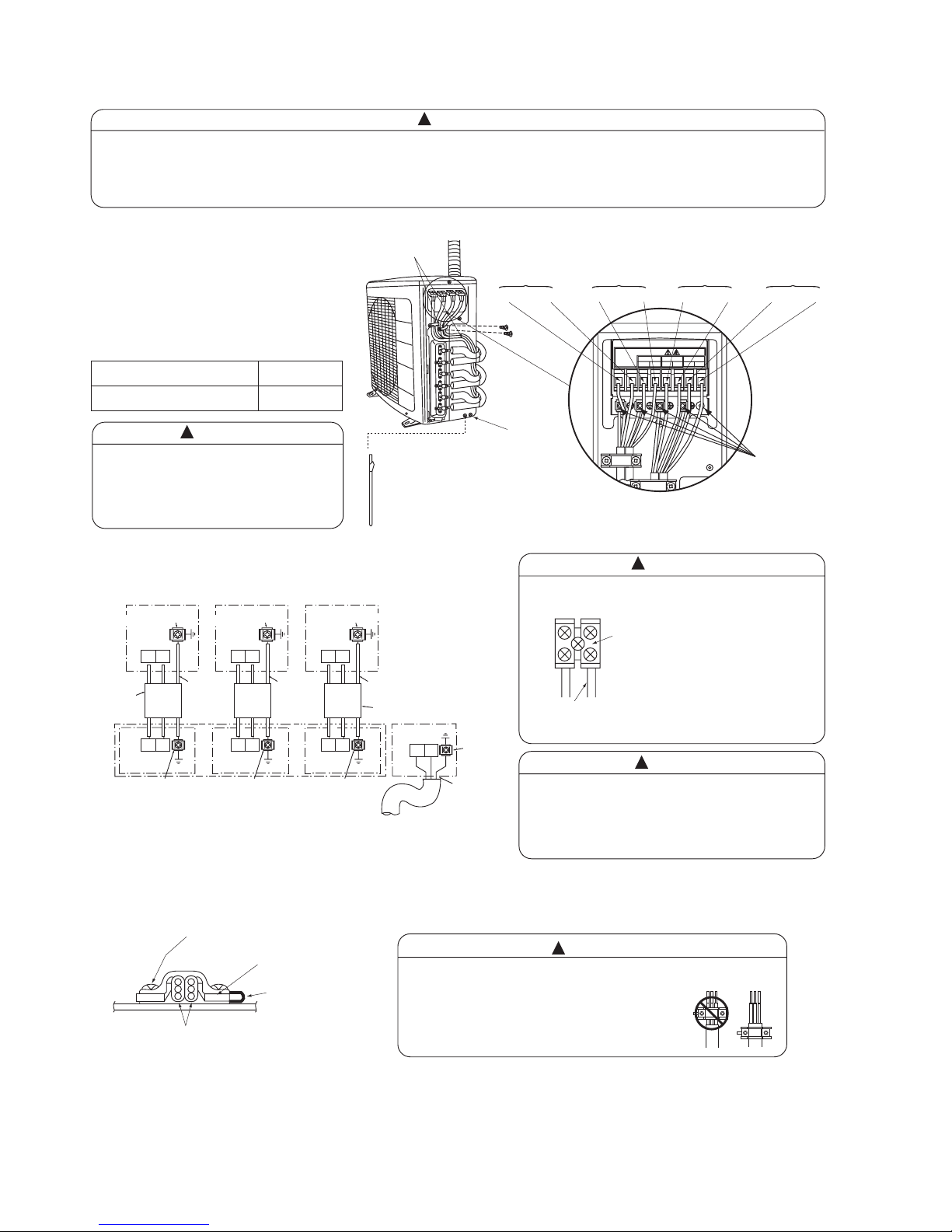
Connection of the connecting cords and power cord. (Outdoor unit)
RAM-55QH4
WARNING
!
WARNING
!
WARNING
!
CAUTION
!
CAUTION
!
Connecting cord should be connected according to Fig.1, that the Indoor unit No. shall match with terminal board No.
of Outdoor unit.
Be sure to fix the connecting cord with the band as shown below. Otherwise water leakage causes short circuit or faults.
Bind connecting cords to
make them fit between the
convex sections.
Earth wire
Earth
Circuit breaker
LN C1D1C
2
D
2
Indoor unit 1 Indoor unit 2
Terminal indications
Grounding rod (optional)
Earth line and grounding rod are not supplied.
Please use optional items below.
•
•
•
•
•
•
•
( )
If earth line cannot be taken from
the power supply connection, use
the optional grounding rod to do
earthing.
Type of grounding rod
SP-EB-2
Length
900mm
Connection of the power cord and connecting
cord
Securely screw in the power cord
and connecting cord so that it will not
get loose or disconnect.
Tightening torque reference value:
1.2 to 1.6 N•m (12 to 16 kgf•cm)
Excessive tightening may damage
the interior of the cord requiring
replacement.
Power cord and
Connecting cord
To prevent a connection error, connecting cords
should be bundled and taped to each respective
pipe. If connecting cords are mixed with other indoor
units, a refrigeration cycle abnormality may occur,
causing dripping.
Leave some space in the connecting cord for maintenance purpose
and be sure to secure it with the cord band.
Secure the connecting cord along the coated part
of the wire using the cord band. Do not exert
pressure on the wire as this may cause
overheating or fire.
When putting two connecting cords through the band.
•
Hold the handle of the side cover, slide down and take off the corner hook, then pull. Reverse these steps when installing.
Page 21
– 20 –
Screw for ground, earth screw
Outdoor Unit
Wiring pattern
Indoor Unit
Fig. 1
Power cord
Screw
Insulating plate
Cord band
Connecting cord
CD
C1 D1
Indoor unit No. 1
Screw for ground, earth screw
Screw for ground, earth screw
For Indoor unit No. 1
Terminal board
Terminal board
Connecting cord
Ø1.6 or 2.0
Green-andYellow
CD
C2 D2
Indoor unit No. 2
Screw for ground, earth screw
Screw for ground, earth screw
For Indoor unit No. 2
Terminal board
Terminal board
Green-andYellow
CD
C3 D3
LN
Indoor unit No. 3
Screw for ground, earth screw
Screw for ground,
earth screw
For Indoor unit No. 3
Terminal board
Terminal board
Terminal board
Connecting cord
Ø1.6 or 2.0
Green-and-Yellow
Green-and-Yellow
AC 220V~240V ONLY
LN
INDOOR 1
C1D1C2 D2
INDOOR 2
C3 D3
INDOOR 3
Connection of the connecting cords and power cord. (Outdoor unit)
RAM-65QH4
WARNING
!
WARNING
!
WARNING
!
CAUTION
!
CAUTION
!
Connecting cord should be connected according to Fig.1, that the Indoor unit No. shall match with terminal board No.
of Outdoor unit.
Be sure to fix the connecting cord with the band as shown below. Otherwise water leakage causes short circuit or faults.
Bind connecting cords to
make them fit between the
convex sections.
Earth wire
Earth
Circuit breaker
LN C1D
1
C
2
D
2
C
3
D
3
Indoor unit 1 Indoor unit 2 Indoor unit 3
Terminal indications
Grounding rod (optional)
Earth line and grounding rod are not supplied.
Please use optional items below.
•
•
•
•
•
•
•
( )
If earth line cannot be taken from
the power supply connection, use
the optional grounding rod to do
earthing.
Type of grounding rod
SP-EB-2
Length
900mm
Connection of the power cord and connecting
cord
Securely screw in the power cord
and connecting cord so that it will not
get loose or disconnect.
Tightening torque reference value:
1.2 to 1.6 N•m (12 to 16 kgf•cm)
Excessive tightening may damage
the interior of the cord requiring
replacement.
Power cord and
Connecting cord
To prevent a connection error, connecting cords
should be bundled and taped to each respective
pipe. If connecting cords are mixed with other indoor
units, a refrigeration cycle abnormality may occur,
causing dripping.
Leave some space in the connecting cord for maintenance purpose
and be sure to secure it with the cord band.
Secure the connecting cord along the coated part
of the wire using the cord band. Do not exert
pressure on the wire as this may cause
overheating or fire.
When putting two connecting cords through the band.
•
Hold the handle of the side cover, slide down and take off the corner hook, then pull. Reverse these steps when installing.
Page 22
– 21 –
CONSTRUCTION AND DIMENSIONAL DIAGRAM
MODEL RAM-55QH4
Handle
Air suction
grille
10464
26 850 79
22 20
Indoor unit 1
Service valve (ø6.35)
Indoor unit 2
Service valve (ø6.35)
Indoor unit 1
Service valve (ø9.52)
Indoor unit 2
Service valve (ø9.52)
298
340
Unit: mm
201
107.5 52 52 52
650
638
Air outlet
1010
10
320
340
Holes for anchor bolt
(2-ø12)
Fixing hole
507 198
57
12
37
Notch for anchor bolt
(2-ø12 Notchs)
More than
More than
More than
100
More than
700
100
100
Service space
ATTENTION
During service, before opening the side cover, please switch off power supply.
Note:
1. Insulated pipes should be used for both small and large diameter pipes.
2. Piping length should be within 25m for one room and within 35m in total.
3. Height difference of piping between indoor unit and outdoor unit should be within 10m.
4. Overhead clearance of outdoor unit should be 200mm to allow servicing.
5. For electrical connection, please refer to the installation manual.
Page 23
– 22 –
CONSTRUCTION AND DIMENSIONAL DIAGRAM
MODEL RAM-65QH4
Handle
Air suction
grille
10464
26 850 79
22 20
Indoor unit 1
Service valve (ø6.35)
Indoor unit 2
Service valve (ø6.35)
Indoor unit 3
Service valve (ø6.35)
Indoor unit 1
Service valve (ø9.52)
Indoor unit 2
Service valve (ø9.52)
Indoor unit 3
Service valve (ø9.52)
298
340
Unit: mm
201
107.5 52 52 52 52 52
650
638
Air outlet
1010
10
320
340
Holes for anchor bolt
(2-ø12)
Fixing hole
507 198
57
12
37
Notch for anchor bolt
(2-ø12 Notchs)
More than
More than
More than
100
More than
700
100
100
Service space
ATTENTION
During service, before opening the side cover, please switch off power supply.
Note:
1. Insulated pipes should be used for both small and large diameter pipes.
2. Piping length should be within 25m for one room and within 45m in total.
3. Height difference of piping between indoor unit and outdoor unit should be within 10m.
4. Overhead clearance of outdoor unit should be 200mm to allow servicing.
5. For electrical connection, please refer to the installation manual.
Page 24
– 23 –
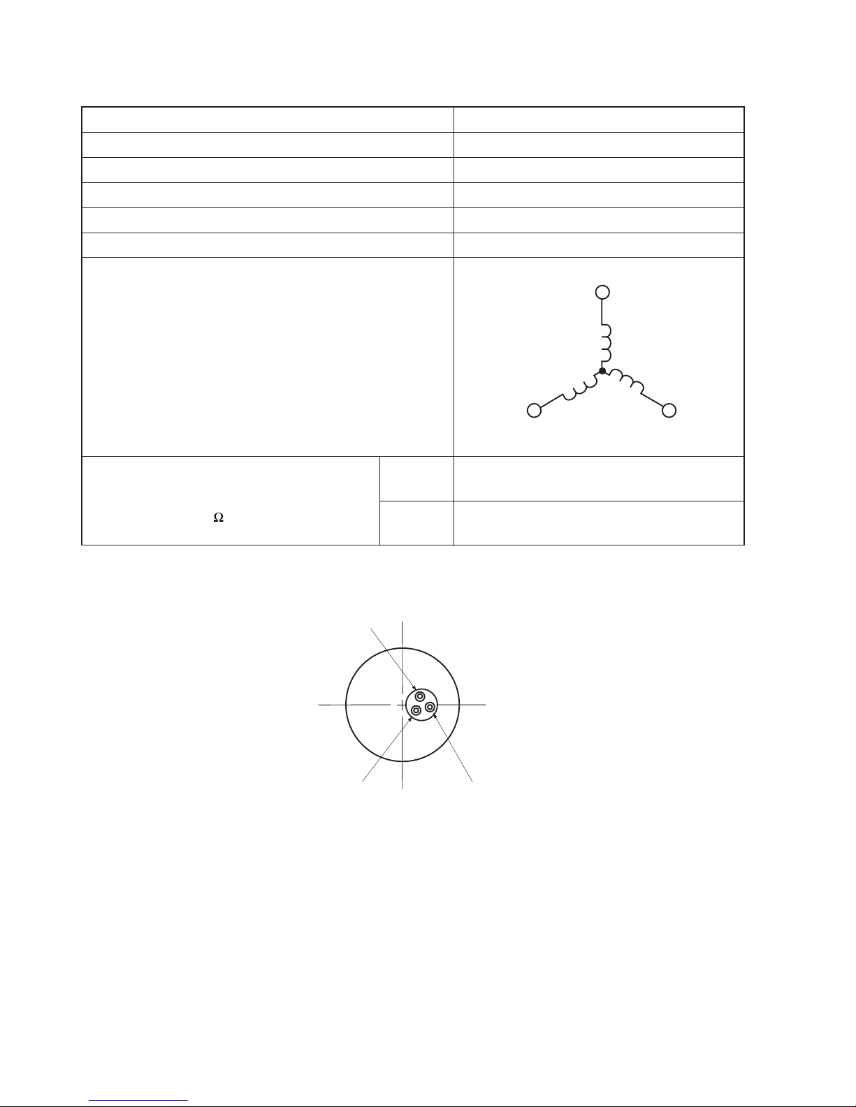
MAIN PARTS COMPONENT
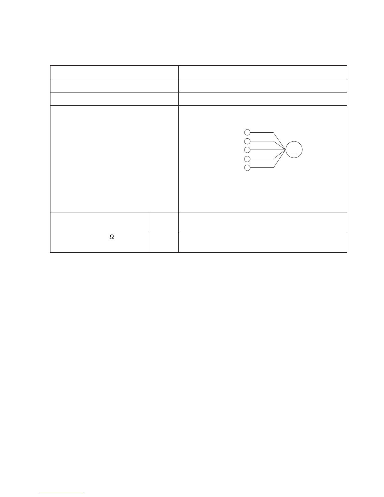
FAN MOTOR
Fan Motor Specifications
CONNECTION
MODEL
POWER SOURCE
OUTPUT
BLU : BLUE YEL : YELLOW BRN : BROWN WHT : WHITE
GRY : GRAY ORN : ORANGE GRN : GREEN RED : RED
BLK : BLACK PNK : PINK VIO : VIOLET
RAM-55QH4 / RAM-65QH4
DC : 140-330V
40W
RESISTANCE VALUE
( )
20˚C
(68˚F)
75˚C
(167˚F)
—
—
M
RED
BLK
WHT
YEL
BLU
(Control circuit built in)
140-330V
15V
0V
0-6V
0-15V
Page 25
– 24 –
MODEL
COMPRESSOR MODEL
PHASE
RATED VOLTAGE
RATED FREQUENCY
POLE NUMBER
COMPRESSOR
Compressor Motor Specifications
CONNECTION
25°C
(68°F)
75°C
(167°F)
(
)
RESISTANCE VALUE
2M = 1.063
2M = 1.268
RAM-55QH4 / RAM-65QH4
JU1013D2
SINGLE
DC: 280-330V
50Hz
4
(U)
(V)
(W)
M
M
M
WHITE
YELLOW
RED
WHITE
RED
YELLOW
Page 26

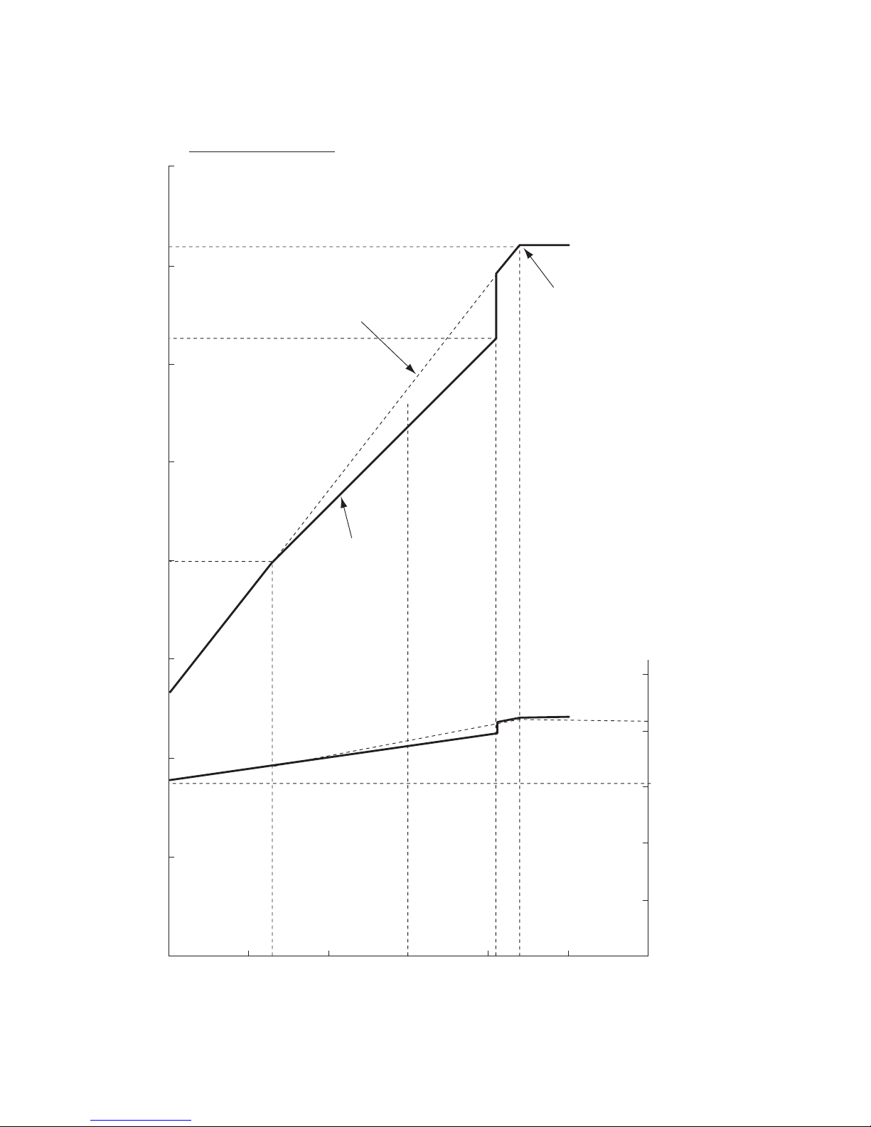
– 25 –
7
6
RATING
CAPACITY
WHEN
TWO
COOLING CAPACITY ( ROOM TEMPERATURE 27˚C )
INDOOR
UNITS
OPERATE
5
5. 10
1060
1520
1740
1795
1920
5. 42
5. 55
5. 40
5. 00
4
3
2
1
0
3000
2000
1000
INPUT (W)
AMBIENT TEMP (˚C)
COOLING CAPACITY (kW)
0
20 25 30 35 40
45
CAPACITY DIAGRAM (RELATED TO THE AMBIENT TEMPERATURE)
MODEL : RAM-55QH4
Page 27
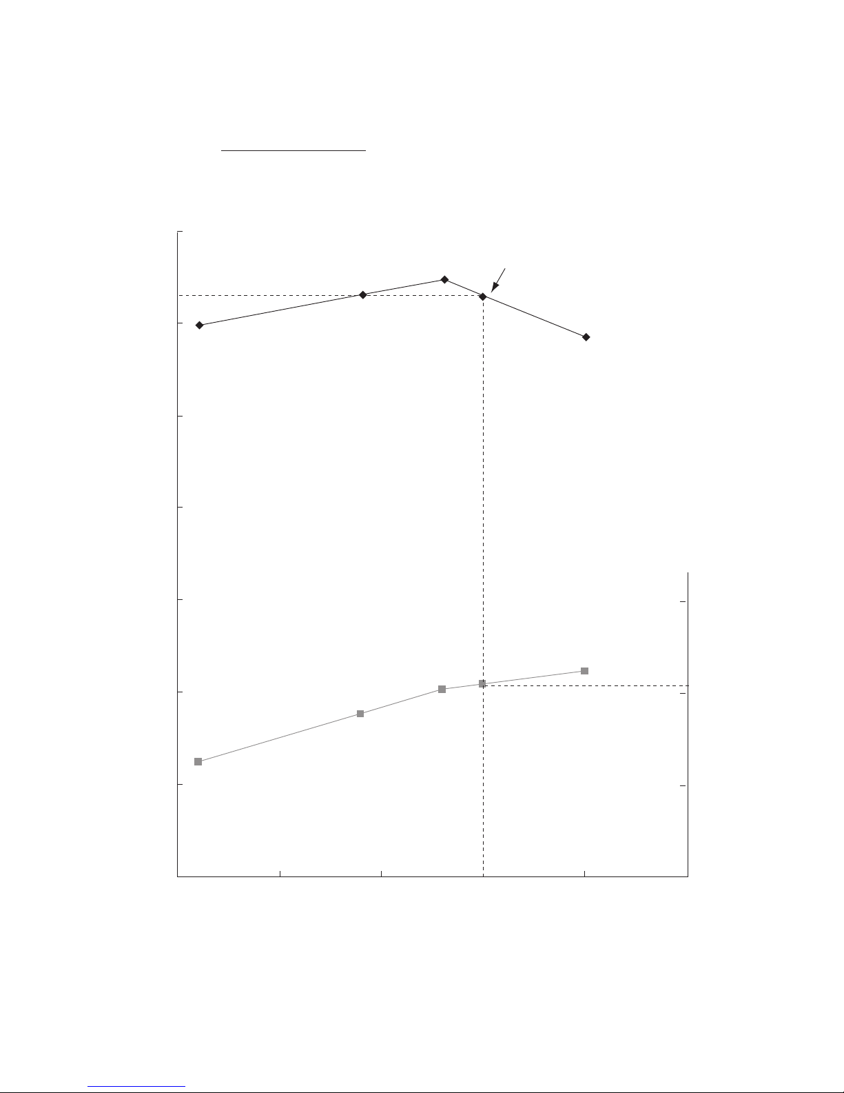
– 26 –
RATING
CAPACITY
MAX CAPACITY
OUTDOOR UNIT
WITHOUT FROST
OUTDOOR UNIT
WITH FROST
WHEN
TWO
HEATING CAPACITY ( ROOM TEMPERATURE 20˚C )
INDOOR
UNITS
OPERATE
0. 0 0
7. 0˚C5. 5˚C–8. 5˚C
500
1000
2000
1500
2500
1. 0
2. 0
3. 0
4. 0
5. 0
6. 0
7. 0
8. 0
INPUT (W)
AMBIENT TEMP. (˚C)
HEATING CAPACITY (kW)
–15 –10 –50 51015
CAPACITY DIAGRAM (RELATED TO THE AMBIENT TEMPERATURE)
MODEL : RAM-55QH4
Page 28
– 27 –
7
6
RATING
CAPACITY
WHEN
THREE
COOLING CAPACITY ( ROOM TEMPERATURE 27˚C )
INDOOR
UNITS
OPERATE
5
4
3
2
1
0
3000
2000
1000
INPUT (W)
AMBIENT TEMP (˚C)
COOLING CAPACITY (kW)
0
20 25 30 35 40
45
5. 95
1240
1765
2030
2095
2240
6. 32
6. 50
6. 30
5. 85
CAPACITY DIAGRAM (RELATED TO THE AMBIENT TEMPERATURE)
MODEL : RAM-65QH4
Page 29
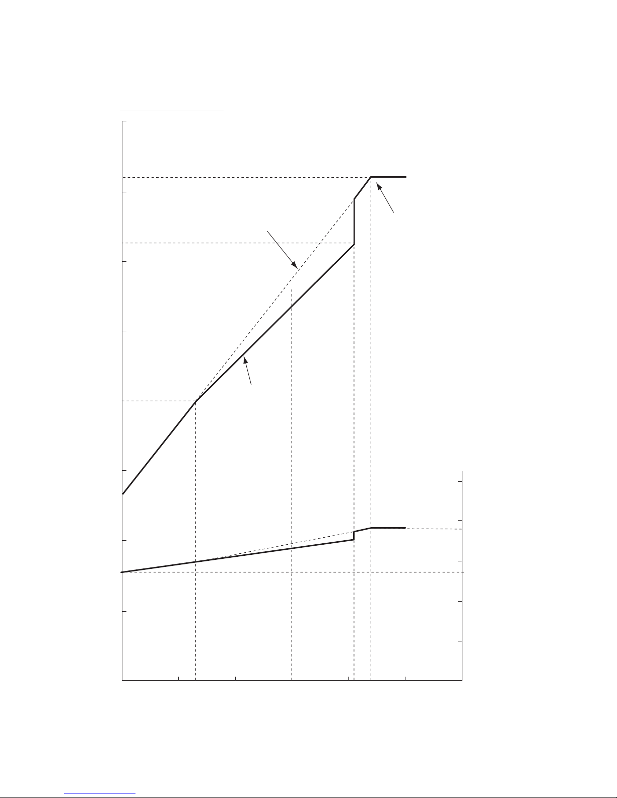
– 28 –
RATING
CAPACITY
MAX CAPACITY
OUTDOOR UNIT
WITHOUT FROST
OUTDOOR UNIT
WITH FROST
WHEN
THREE
HEATING CAPACITY ( ROOM TEMPERATURE 20˚C )
INDOOR
UNITS
OPERATE
0. 0
0
7. 0˚C5. 5˚C
–8. 5˚C
500
1000
2000
1500
2500
1. 0
2. 0
3. 0
4. 0
5. 0
6. 0
7. 0
8. 0
INPUT (W)
AMBIENT TEMP. (˚C)
HEATING CAPACITY (kW)
–15 –10 –50 51015
CAPACITY DIAGRAM (RELATED TO THE AMBIENT TEMPERATURE)
MODEL : RAM-65QH4
Page 30
– 29 –
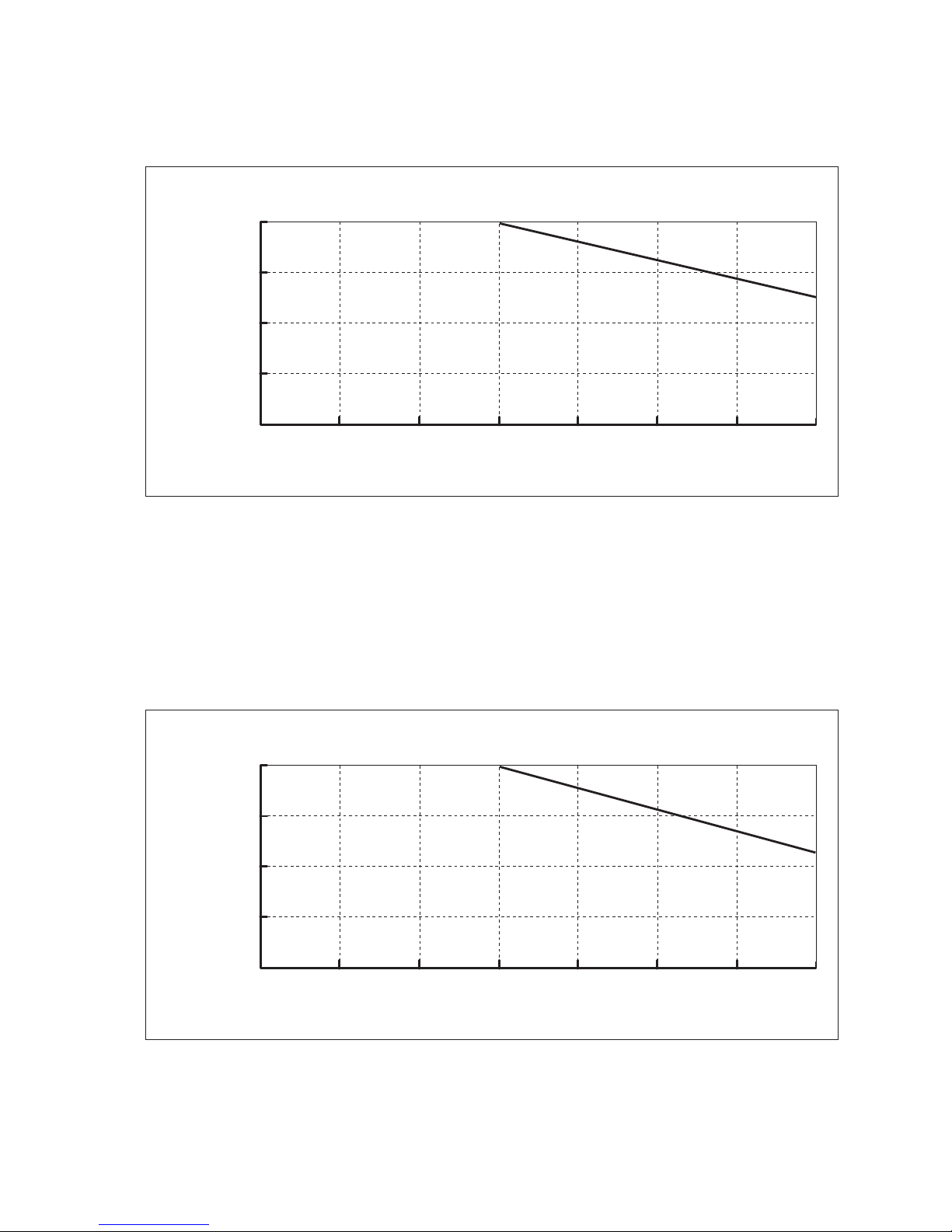
CAPACITY DIAGRAM (RELATED TO THE PIPING LENGTH)
MODEL : RAM-55QH4
1. 0
0. 9
0. 8
0. 7
0. 6
0 5 10 20 3025 3515
PIPING LENGTH (m)
CHANGE RATIO OF
CAPACITY
HEATING
1. 0
0. 9
0. 8
0. 7
0. 6
0 5 10 20 3025 3515
PIPING LENGTH (m)
CHANGE RATIO OF
CAPACITY
COOLING
Page 31

– 30 –
CAPACITY DIAGRAM (RELATED TO THE PIPING LENGTH)
MODEL : RAM-65QH4
Page 32

– 31 –
90
80
70
60
50
40
30
20
10
63 125 250 500 1000 2000 4000 8000
Sound Level
[
dB
]
wavelengthMainbandOctave
[
Hz
]
pressure
APPROXIMATE
THRESHOLD
FOR
NOISE
CONTINUROUS
HEARING
NC-40
NC-20
NC-30
NC-50
NC-60
NC-70
SOUND PRESSURE LEVEL
MODEL : RAM-55QH4 / RAM-65QH4 (Heating)
Page 33

– 32 –
90
80
70
60
50
40
30
20
10
63 125 250 500 1000 2000 4000 8000
Sound Level
[
dB
]
wavelengthMainbandOctave
[
Hz
]
pressure
APPROXIMATE
THRESHOLD
FOR
NOISE
CONTINUROUS
HEARING
NC-40
NC-20
NC-30
NC-50
NC-60
NC-70
SOUND PRESSURE LEVEL
MODEL : RAM-55QH4 / RAM-65QH4 (Cooling)
Page 34

GRY
5
WHT
10
RED
~
+
~
-
1111
CN6 (BLU)
(GRY)
CN3
(BLU)
CN4
CN2
(BLK)
CN1
(WHT)
(WHT)
CN40
CN7
(RED)
(WHT)
CN30
5
CN3A
(WHT)
CN11
(WHT)
CN41
(WHT)
CN14
(WHT)
CN15
(WHT)
ORN
GRY
CN5 (WHT)
(RED)
CN10
CN16
(RED)
CN13
(WHT)
CN8
(RED)
CN9
(WHT)
CN12
(WHT)
BRN
RED
GRN1
CN31
(WHT)
(WHT)
CN14
(WHT)
CN11
(WHT)
CN13
GRN3
5
U
V
YEL
RED
W
L2
YEL
+
L1
–
2
+
-
+
25A FUSE
5A FUSE
BLK
WHT
BLU
~
~
YEL
YEL
+
L
N
D1
C1
C2
D2
(BRN)
(BLU)
(GRN + YEL)
TERMINAL
BOARD
SW POWER
CIRCUIT
(RED)
(GRN + YEL)
(BRN)
POWER SOURCE
AC220-240V
50Hz
INDOOR UNIT 1
(GRN + YEL)
(RED)
INDOOR UNIT 2
(BRN)
U
V
W
WHT
YEL
RED
COMPRESSOR
!
SYSTEM
POWER MODULE
REACTOR
DIODE STACK
(D15VBA60)
POWER RELAY
ICP RELAY
NF COIL 1 COILVARISTOR 1
VARISTOR 3
POWER P.W.B.
MAIN P.W.B.
C002 C001
C025 C024
C023 C022
L007
C003
R004
C006
R002
VARISTOR 2
R005
DIODE STACK
C021
C020
REVERSING
VALVE
FAN MOTOR
BLU : BLUE
GRY : GRAY
BLK : BLACK
YEL : YELLOW
ORN : ORANGE
PNK : PINK
BRN : BROWN
GRN : GREEN
VIO : VIOLET
WHT : WHITE
RED : RED
LEGEND
!
!
! !
!
!
!
!
!
!
!
!
!
!
!
CAUTION
The marked parts are very important ones for safety.
FM
OUTDOOR THERMISTOR
DEF THERMISTOR
OH THERMISTOR
NARROW PIPE THERMISTOR 1
NARROW PIPE THERMISTOR 2
WIDE PIPE THERMISTOR 1
WIDE PIPE THERMISTOR 2
M M
ELECTRIC EXPANSION
VALVE (FOR INDOOR 1)
ELECTRIC EXPANSION
VALVE (FOR INDOOR 2)
MODEL RAM-55QH4
WIRING DIAGRAM
– 33 –
OUTDOOR UNIT
Page 35

GRY
5
WHT
10
RED
~
+
~
-
1111
CN6 (BLU)
(GRY)
CN3
(BLU)
CN4
CN2
(BLK)
CN1
(WHT)
(WHT)
CN40
CN7
(RED)
(WHT)
CN30
5
CN3A
(WHT)
CN11
(WHT)
CN41
(WHT)
CN14
(WHT)
CN15
(WHT)
ORN
GRY
CN5 (WHT)
(RED)
CN10
CN16
(RED)
CN13
(WHT)
CN8
(RED)
CN17
(BLU)
CN9
(WHT)
CN12
(WHT)
BRN
RED
GRN1
CN31
(WHT)
(WHT)
CN14
(WHT)
CN11
(WHT)
CN13
YEL
GRN3
5
BLU
U
V
YEL
RED
W
L2
YEL
+
L1
–
2
+
-
+
25A FUSE
5A FUSE
BLK
WHT
BLU
~
~
YEL
YEL
+
L
N
D1
C1
D3
C3
C2
D2
(BRN)
(BLU)
(GRN + YEL)
TERMINAL
BOARD
SW POWER
CIRCUIT
(RED)
(GRN + YEL)
(BRN)
POWER SOURCE
AC220-240V
50Hz
INDOOR UNIT 1
(GRN + YEL)
(RED)
INDOOR UNIT 2
(BRN)
(GRN + YEL)
(RED)
INDOOR UNIT 3
(BRN)
U
V
W
WHT
YEL
RED
COMPRESSOR
!
SYSTEM
POWER MODULE
REACTOR
DIODE STACK
(D15VBA60)
POWER RELAY
ICP RELAY
NF COIL 1 COILVARISTOR 1
VARISTOR 3
POWER P.W.B.
MAIN P.W.B.
C002 C001
C025 C024
C023 C022
L007
C003
R004
C006
R002
VARISTOR 2
R005
DIODE STACK
C021
C020
REVERSING
VALVE
FAN MOTOR
BLU : BLUE
GRY : GRAY
BLK : BLACK
YEL : YELLOW
ORN : ORANGE
PNK : PINK
BRN : BROWN
GRN : GREEN
VIO : VIOLET
WHT : WHITE
RED : RED
LEGEND
!
!
! !
!
!
!
!
!
!
!
!
!
!
!
CAUTION
The marked parts are very important ones for safety.
FM
OUTDOOR THERMISTOR
DEF THERMISTOR
OH THERMISTOR
NARROW PIPE THERMISTOR 1
NARROW PIPE THERMISTOR 2
NARROW PIPE THERMISTOR 3
WIDE PIPE THERMISTOR 1
WIDE PIPE THERMISTOR 2
WIDE PIPE THERMISTOR 3
M M M
ELECTRIC EXPANSION
VALVE (FOR INDOOR 1)
ELECTRIC EXPANSION
VALVE (FOR INDOOR 2)
ELECTRIC EXPANSION
VALVE (FOR INDOOR 3)
MODEL RAM-65QH4
WIRING DIAGRAM
– 35 –
OUTDOOR UNIT
Page 36

Remote Control
CIRCUIT DIAGRAM
– 37 –
1
2
3
4
5
6
7
8
10
11
13
14
15
16
17
19
20
9
12
18
SEG19
SEG18
SEG17
SEG16
SEG21
SEG24
SEG25
SEG26
SEG27
SEG28
NC
NC
NC
NC
NC
NC
NC
NC
NC
SEG20
SEG5
SEG0
SEG1
SEG2
SEG3
SEG4
SEG5
SEG6
SEG7
COM3
COM2
COM1
COM0
SEG14
SEG13
SEG12
SEG11
SEG13
SEG9
SEG8
40
39
38
37
36
35
34
33
31
30
28
27
26
25
24
22
21
32
29
23
40
39
38
37
36
35
34
33
31
30
28
27
26
25
32
29
64
63
62
61
60
59
58
57
56
55
54
53
52
51
50
49
48 47
46
45
44
43
41
42
65
66
67
68
69
70
71
72
74
75
77
78
79
80
73
76
1
2
3
4
5
6
7
8
9
10
11
12
13
14
15
16
17 18
19
20
21
22
24
23
SEG20
SEG21
SEG22
SEG23
SEG24
SEG25
SEG26
SEG27
SEG28
SEG29
SEG30
SEG31
SEG32
SEG33
SEG34
SEG35
SEG19
SEG18
SEG17
SEG16
SEG15
SEG14
SEG13
SEG12
SEG11
SEG10
SEG9
SEG8
SEG7
SEG6
SEG5
SEG4
SEG3
SEG2
SEG1
SEG0
SEG43
SEG42
SEG41
SEG40
P40
P41
P42
P43
P00
P01
P02
P03
P10
P11
P12
P13
D0
D1
D2
D3
D4
D5
D6
D7
D8
D9
BEEP
P20
P30
P31
NCVL C1
VL C2
VL C3
XC IN
XC OUT
VDD
X OUT
X IN
RESET
CARR
P23
P22
P21
VSS
IC 1
M3455OM6A-504FP
LCD 1
C8
50v/1u
K 1
D3
RB425D(1/2)
K2K3
K4
K5
P10
P11
P12
K6
K7 K8
K8 K10
K11K12
K18
K17
K15 K16
K13 K14
D0
D1
D2
D3
R1
100k
SW1
R2
P
100k
R3
100k
R4
100k
R5
Q1
2SC3443
or 2SC2982
R6
R7
R9
D2D1
D1 D2
EL-1L7
D3
(1/2)
RB425D
R10
12M
K19
X1
C9
R11
R15
R16
R13
R14
910kHz
105
104
104
150k
X2
kHz
C4
C5
C6
C7
18p
22p
R12
220k
220K
220k
100k
100k
32.768
C1
C2
C3
220p
220p
334
R6 R9
24(1/8W)
R8
330
SW-187-2P
Key matrix table
Input
D3D2D1
D0
Output
Door open Automatic swingFan speed selectionOperation selectionStart/Stop
Door shut ––Super silent coolingStart/Stop
Door open Day
• present timeHour downHour upOn timer
Door shut Super coolingRoom temperature downRoom temperature up–
Door open CancelReservation–Off timer
Door shut –––Sleep
P10
P11
P12
Page 37

CIRCUIT DIAGRAM
MODEL RAM-55QH4
– 39 –
L
C023
C022
C002
C001
C025
C024
N
Page 38

CIRCUIT DIAGRAM
MODEL RAM-65QH4
– 41 –
L
C023
C022
C002
C001
C025
C024
N
Page 39

– 43 –
BLOCK DIAGRAM
MODEL RAM-55QH4
Outdoor micro computer (6S00)
Magnetic relay
Inrush current
protection relay
M
L
N
Rotor position
detector
Overload current
detector
SPM driver
Overheat
thermistor
Defrost
thermistor
Outdoor temp
thermistor
Indoor/Outdoor
Interface 1
Indoor/Outdoor
Interface 2
Switching power supply 2
Switching power supply 1
Reset circuit
Clock circuit
Multiplexer
Expansion valve
thermistor 1
Expansion valve
thermistor 2
Expansion valve 1
Expansion valve 2
Expansion valve
drive circuit
Reversing valve
drive circuit
Reversing valve
EEPROM
Fan motor
drive circuit
M
compressor
fan motor
Indoor unit 1
Indoor unit 2
C1/D1
C2/D2
Power source
single phase 50Hz, 220-240V
Outdoor Unit
System
Power
Module
Page 40

– 44 –
BLOCK DIAGRAM
MODEL RAM-65QH4
Outdoor micro computer (6S00)
Magnetic relay
Inrush current
protection relay
M
L
N
Rotor position
detector
Overload current
detector
SPM driver
Overheat
thermistor
Defrost
thermistor
Outdoor temp
thermistor
Indoor/Outdoor
Interface 1
Indoor/Outdoor
Interface 2
Indoor/Outdoor
Interface 3
Switching power supply 2
Switching power supply 1
Reset circuit
Clock circuit
Multiplexer
Expansion valve
thermistor 3
Expansion valve
thermistor 1
Expansion valve
thermistor 2
Expansion valve 1
Expansion valve 2
Expansion valve 3
Expansion valve
drive circuit
Reversing valve
drive circuit
Reversing valve
EEPROM
Fan motor
drive circuit
M
compressor
fan motor
Indoor unit 1
Indoor unit 2
Indoor unit 3
C1/D1
C2/D2
C3/D3
Power source
single phase 50Hz, 220-240V
Outdoor Unit
System
Power
Module
Page 41

– 45 –
Page 42

– 47 –
MODEL
PROM
NO.
0A2
RTOTSA ˚C2.00 ˚C2.00 ˚C2.00
144 SHIFTW_M
˚C2.33 ˚C2.33 ˚C2.33
145 SFTSZW_M
˚C2.33 ˚C2.33 ˚C2.33
146 SHIFTC_M
˚C1.33 ˚C1.33 ˚C0.00
147 SHIFTD_M
˚C0.00 ˚C0.00 ˚C0.00
148
CLMXTP_M
˚C30.00 ˚C30.00 ˚C30.00
149 YNEOF_M
˚C20.00 ˚C20.00 ˚C20.00
14E TEION_M
˚C2.00 ˚C2.00 ˚C2.00
14F TEIOF_M
˚C9.00 ˚C9.00 ˚C9.00
157
CMNLMT_M
min
-1
1950 min
-1
1950 min
-1
1950
178 FWSS_M
min
-1
500 min
-1
500 min
-1
500
179 FWSOY_M
min
-1
830 min
-1
830 min
-1
830
17A FWS_M
min
-1
850 min
-1
880 min
-1
920
17B FWKAF_M
min
-1
1050 min
-1
1050 min
-1
1000
17C FWL_M
min
-1
990 min
-1
1020 min
-1
1130
17D FWAH_M
min
-1
1060 min
-1
1100 min
-1
1250
17E FWH_M
min
-1
1080 min
-1
1130 min
-1
1270
17F
FWHH_M min
-1
1080 min
-1
1130 min
-1
1270
180
FCSOY_M min
-1
650 min
-1
650 min
-1
700
181
FCS_M min
-1
700 min
-1
730 min
-1
800
182
FCL_M min
-1
820 min
-1
900 min
-1
1040
183
FCAH_M min
-1
920 min
-1
1000 min
-1
1240
184
FCH_M min
-1
960 min
-1
1050 min
-1
1290
185
FCHH_M min
-1
1060 min
-1
1100 min
-1
1310
186
FDOY_M min
-1
700 min
-1
730 min
-1
800
187
FDS1_M min
-1
700 min
-1
730 min
-1
800
188
FDS2_M
FWSOY_MSleep
FWSS_MUltra Lo
Label nameFan speed mode
Label nameOperation mode
Heating operation
Operation
mode
Heating
operation
Cooling
operation
Dehumidifying
operation
Table 1 Fan speed by mode
Table 2 Room temperature shift value
FWS_MLo
Hi
Hi
Hi
Hi
FWKAF_MOverload
FCSOY_MSleep
FWHH_MUltra Hi
FCS_MLo
FCL_MMed
FDOY_MSleep
FCHH_MUltra Hi
FDS1_MLo 1
FDS2_MLo 2
FWL_MMed
FWAH_M
Set fan speed "AUTO"
FWH_M
Set fan speed "HI"
FCAH_M
Set fan speed "AUTO"
FCH_M
Set fan speed "HI"
SHIFTW_M
Fan speed "AUTO, Hi, Med"
SFTSZW_M
Fan speed "Lo, Sleep"
SHIFTC_M
Cooling operation
SHIFTD_M
Dehumidifying operation
min
-1
700 min
-1
730 min
-1
800
120
WMAX_M
min
-1
5300 min
-1
5000 min
-1
4500
121
WMAX2_M
min
-1
5300 min
-1
5000 min
-1
4500
122
WSTD_M
min
-1
4000 min
-1
4000 min
-1
4000
123
WJKMAX_M
min
-1
3700 min
-1
3700 min
-1
4000
124
WBEMAX_M
min
-1
3500 min
-1
3500 min
-1
3700
127
CMAX_M
min
-1
3300 min
-1
3300 min
-1
4000
128
CMAX2_M
min
-1
3300 min
-1
3300 min
-1
4000
129
CSTD_M
min
-1
3250 min
-1
3150 min
-1
3000
12A
CKYMAX_M
min
-1
2800 min
-1
2800 min
-1
2800
12B
CJKMAX_M
min
-1
2750 min
-1
2750 min
-1
2750
12C
CBEMAX_M
min
-1
2500 min
-1
2500 min
-1
2500
12F
SDMAX_M
min
-1
2400 min
-1
1550 min
-1
1800
130
SDRPM_M
min
-1
2100 min
-1
1400 min
-1
1100
138
WMIN_M
min
-1
800 min
-1
800 min
-1
800
139
CMINHI_M
min
-1
800 min
-1
800 min
-1
800
13A
CMIN_M
min
-1
1200 min
-1
1200 min
-1
1200
13B
DMIN_M
min
-1
1200 min
-1
1200 min
-1
1200
13C
PKOU_M
min
-1
550 min
-1
550 min
-1
550
13E
FZZYTM_M
min.4 min.4 min.4
13D
FZZY_GN_M
1.5 1.5 1.5
REQUIRED VALUE
OF UNIT SIDE
REQUIRED VALUE
OF UNIT SIDE
REQUIRED VALUE
OF UNIT SIDE
LABEL NAME
RAK-25NH4 RAK-35NH4 RAK-50NH4
Page 43

– 48 –
09C RTOTSA 2.00 ˚C 2.00 ˚C
120 WMAX_M 5300 min
-1
4500 min
-1
121 WMAX2_M 5300 min-1 4500 min
-1
122 WSTD_M 4000 min-1 4000 min
-1
123
WJKMAX_M
3700 min-1 4000 min
-1
124
WBEMAX_M
3500 min-1 3700 min
-1
125 CMAX_M 3500 min-1 4000 min
-1
126 CMAX2_M 3500 min-1 4000 min
-1
127 CSTD_M 3250 min-1 3100 min
-1
128
CKYMAX_M
2800 min-1 2800 min
-1
129
CJKMAX_M
2750 min-1 2750 min
-1
12A
CBEMAX_M
2500 min-1 2500 min
-1
12B SDMAX_M 2400 min-1 1800 min
-1
12C SDRPM_M 2000 min-1 1100 min
-1
132 WMIN_M 800 min-1 800 min
-1
133 CMINHI_M 800 min-1 800 min
-1
134 CMIN_M 1200 min-1 1200 min
-1
135 DMIN_M 1200 min-1 1100 min
-1
136 PKOU_M 500 min-1 500 min
-1
137
FZZY_GN_M
1.0 1.0
138 FZZYTM_M 3 min. 3 min.
13E SHIFTW_M 2.33 ˚C 2.33 ˚C
13F
SFTSZW_M
0.66 ˚C 0.66 ˚C
140 SHIFTO_M -0.66 ˚C -0.66 ˚C
141 SHIFTD_M -0.66 ˚C -0.66 ˚C
142
CLMXTP_M
30.00 ˚C 30.00 ˚C
143 YNEOF_M 23.00 ˚C 23.00 ˚C
148 TEION_M 2.00 ˚C 2.00 ˚C
149 TEIOF_M 9.00 ˚C 9.00 ˚C
150
CMNLMT_M
1900 min-1 1900 min
-1
16D FWSS_M 400 min-1 400 min
-1
16E FWSOY_M 710 min-1 740 min
-1
16F FWS_M 710 min-1 820 min
-1
170 FWKAF_M 790 min-1 950 min
-1
171 FWL_M 790 min-1 950 min
-1
172 FWAH_M 830 min-1 1040 min
-1
173 FWH_M 870 min-1 1080 min
-1
174 FWHM_M 960 min-1 1100 min
-1
175 FWHH_M 960 min-1 1100 min
-1
176 FCSOY_M 670 min-1 670 min
-1
177 FCS_M 670 min-1 730 min
-1
178 FCL_M 750 min-1 920 min
-1
179 FCAH_M 790 min-11000 min
-1
17A FCH_M 830 min-1 1050 min
-1
17B FCHM_M 880 min-1 1090 min
-1
17C FCHH_M 880 min-1 1090 min
-1
17D FDOY_M 670 min-1 730 min
-1
17E FDS1_M 670 min-1 730 min
-1
17F FDS2_M 670 min-1 730 min
-1
180 FCLN_M 600 min-1 600 min
-1
186 FWOPN_M 1060 min-1 1250 min
-1
187 FCOPN_M 1020 min-1 1090 min
-1
188 FWCLD_M 1060 min-1 1250 min
-1
189 FCCLD_M 1020 min-1 1090 min
-1
18A
FWUDSS_M
400 min-1 400 min
-1
18B
FWUDSOY_M
640 min-1 660 min
-1
18C FWUDS_M 640 min-1 740 min
-1
18D
FWUDKAF_M
710 min-1 860 min
-1
18E FWUDL_M 710 min-1 860 min
-1
18F
FWUDAH_M
750 min-1 950 min
-1
190 FWUDH_M 780 min-1 970 min
-1
191
FWUDHH_M
870 min-1 990 min
-1
192
FCUDSOY_M
600 min-1 660 min
-1
193 FCUDS_M 600 min-1 660 min
-1
194 FCUDL_M 680 min-1 820 min
-1
195
FCUDAH_M
710 min-1 900 min
-1
196 FCUDH_M 750 min-1 940 min
-1
197
FCUDHH_M
790 min-1 980 min
-1
19D
FWUDOPN_M
950 min-1 1100 min
-1
19E
FCUDOPN_M
900 min-1 980 min
-1
MODEL
N O .
LABEL NAME
REQUIRED VALUE
OF UNIT SIDE
REQUIRED VALUE
OF UNIT SIDE
Operation
mode
Fan speed mode
Table 1 Fan speed by mode
Table 2 Room temperature shift value
Label name
Heating
operation
Ultra Lo FWSS_M
Sleep FWSOY_M
Lo FWS_M
Overload FWKAF_M
Med FWL_M
Ultra Lo FWUDSS_M
Sleep FWUDSOY_M
Lo FWUDS_M
Sleep FCSOY_M
Lo FCS_M
Overload FWUDKAF_M
Med FWUDL_M
Med FCL_M
Sleep FCUDSOY_M
Lo FCUDS_M
Sleep FDOY_M
Lo1 FDS1_M
Lo2 FDS2_M
SHIFTW
SFTSZW
SHIFTC
SHIFTD
Med FCUDL_M
Set fan speed "HI"Hi FWH_M
Set fan speed "AUTO"Hi FWAH_M
Set fan speed "AUTO"Hi FWUDAH_M
(When AIR OUTLET SWITCH "ON")
Ultra Hi FWHM_M
Set fan speed "HI"
Hi FWUDH_M
Ultra Hi FWUDHH_M
Set fan speed "AUTO"Hi FCUDAH_M
Set fan speed "HI"
Fan speed "AUTO, Hi, Med"
Fan speed "Lo, Sleep"
Hi FCUDH_M
Ultra Hi FCUDHH_M
(When AIR OUTLET SWITCH "OFF")
Ultra Hi FWHM_M
Set fan speed "HI"Hi FCH_M
Set fan speed "AUTO"Hi FCAH_M
(When AIR OUTLET SWITCH "ON")
Ultra Hi FCHM_M
(When AIR OUTLET SWITCH "OFF")
Ultra Hi FCHH_M
Upper FanUpper Fan Lower FanLower Fan
Cooling
operation
Operation mode Shift value
Heating operation
Cooling operation
Dehumidifying operation
Dehumidi-
fying
operation
RAF-25NH4 RAF-50NH4
Page 44

– 49 –
MODEL
PROM
NO.
0A2
RTOTSA ˚C5.00 ˚C5.00
144 SHIFTW_M
˚C4.00 ˚C4.00
145 SFTSZW_M
˚C5.33 ˚C5.33
146 SHIFTC_M
˚C-1.00 ˚C-1.00
147 SHIFTD_M
˚C-1.00 ˚C-1.00
148
CLMXTP_M
˚C30.00 ˚C30.00
149 YNEOF_M
˚C21.00 ˚C21.00
14E TEION_M
˚C2.00 ˚C2.00
14F TEIOF_M
˚C6.00 ˚C6.00
157
CMNLMT_M
min
-1
1950 min
-1
1950
178 FWSS_M
V
16.0
V
16.0
179 FWSOY_M
V
18.9
V
21.1
17A FWS_M
V
19.9
V
22.1
17B FWKAF_M
V
24.0
V
26.0
17C FWL_M
V
24.0
V
26.0
17D FWAH_M
V
26.0
V
30.1
17E FWH_M
V
27.0
V
32.0
17F
FWHH_M
V
30.1
V
33.0
180
FCSOY_M
V
16.4
V
18.0
181
FCS_M
V
17.0
V
18.9
182
FCL_M
V
19.9
V
24.0
183
FCAH_M
V
22.1
V
27.0
184
FCH_M
V
23.4
V
30.5
185
FCHH_M
V
25.2
V
30.5
186
FDOY_M
V
17.0
V
18.9
187
FDS1_M
V
17.0
V
18.9
188
FDS2_M
FWSOY_MSleep
FWSS_MUltra Lo
Label nameFan speed mode
Label nameOperation mode
Heating operation
Operation
mode
Heating
operation
Cooling
operation
Dehumidifying
operation
Table 1 Fan speed by mode
Table 2 Room temperature shift value
FWS_MLo
Hi
Hi
Hi
Hi
FWKAF_MOverload
FCSOY_MSleep
FWHH_MUltra Hi
FCS_MLo
FCL_MMed
FDOY_MSleep
FCHH_MUltra Hi
FDS1_MLo 1
FDS2_MLo 2
FWL_MMed
FWAH_M
Set fan speed "AUTO"
FWH_M
Set fan speed "HI"
FCAH_M
Set fan speed "AUTO"
FCH_M
Set fan speed "HI"
SHIFTW_M
Fan speed "AUTO, Hi, Med"
SFTSZW_M
Fan speed "Lo, Sleep"
SHIFTC_M
Cooling operation
SHIFTD_M
Dehumidifying operation
V
17.0
V
18.9
120
WMAX_M
min
-1
5300 min
-1
4500
121
WMAX2_M
min
-1
5300 min
-1
4500
122
WSTD_M
min
-1
4000 min
-1
3700
123
WJKMAX_M
min
-1
3700 min
-1
3700
124
WBEMAX_M
min
-1
3500 min
-1
3500
127
CMAX_M
min
-1
3500 min
-1
3500
128
CMAX2_M
min
-1
3500 min
-1
3500
129
CSTD_M
min
-1
3250 min
-1
3000
12A
CKYMAX_M
min
-1
2850 min
-1
2850
12B
CJKMAX_M
min
-1
2700 min
-1
2700
12C
CBEMAX_M
min
-1
2000 min
-1
2000
12F
SDMAX_M
min
-1
2400 min
-1
1800
130
SDRPM_M
min
-1
2000 min
-1
1500
138
WMIN_M
min
-1
800 min
-1
800
139
CMINHI_M
min
-1
800 min
-1
800
13A
CMIN_M
min
-1
1000 min
-1
1000
13B
DMIN_M
min
-1
1000 min
-1
1000
13C
PKOU_M
min
-1
500 min
-1
500
13E
FZZYTM_M
min.3 min.3
13D
FZZY_GN_M
1.0 1.0
REQUIRED VALUE
OF UNIT SIDE
REQUIRED VALUE
OF UNIT SIDE
LABEL NAME
RAM-55QH4 RAM-65QH4
Page 45

– 50 –
MODEL
PROM
NO.
0A2
RTOTSA ˚C2.00 ˚C2.00
144 SHIFTW_M
˚C5.00 ˚C5.00
145 SFTSZW_M
˚C5.00 ˚C5.00
146 SHIFTC_M
˚C1.66 ˚C1.66
147 SHIFTD_M
˚C1.66 ˚C1.66
148
CLMXTP_M
˚C30.00 ˚C30.00
149 YNEOF_M
˚C20.00 ˚C20.00
14E TEION_M
˚C2.00 ˚C2.00
14F TEIOF_M
˚C9.00 ˚C9.00
157
CMNLMT_M
min-10 min
-1
0
178 FWSS_M
V
13.1
V
13.1
179 FWSOY_M
V
17.6
V
17.6
17A FWS_M
V
20.3
V
20.3
17B FWKAF_M
V
22.9
V
22.9
17C FWL_M
V
22.9
V
22.9
17D FWAH_M
V
27.9
V
27.9
17E FWH_M
V
28.3
V
28.3
17F
FWHH_M
V
28.3
V
28.3
180
FCSOY_M
V
18.0
V
18.0
181
FCS_M
V
20.5
V
20.5
182
FCL_M
V
24.0
V
24.0
183
FCAH_M
V
27.9
V
27.9
184
FCH_M
V
27.9
V
27.9
185
FCHH_M
V
27.9
V
27.9
186
FDOY_M
V
18.0
V
18.0
187
FDS1_M
V
20.5
V
20.5
188
FDS2_M
FWSOY_MSleep
FWSS_MUltra Lo
Label nameFan speed mode
Label nameOperation mode
Heating operation
Operation
mode
Heating
operation
Cooling
operation
Dehumidifying
operation
Table 1 Fan speed by mode
Table 2 Room temperature shift value
FWS_MLo
Hi
Hi
Hi
Hi
FWKAF_MOverload
FCSOY_MSleep
FWHH_MUltra Hi
FCS_MLo
FCL_MMed
FDOY_MSleep
FCHH_MUltra Hi
FDS1_MLo 1
FDS2_MLo 2
FWL_MMed
FWAH_M
Set fan speed "AUTO"
FWH_M
Set fan speed "HI"
FCAH_M
Set fan speed "AUTO"
FCH_M
Set fan speed "HI"
SHIFTW_M
Fan speed "AUTO, Hi, Med"
SFTSZW_M
Fan speed "Lo, Sleep"
SHIFTC_M
Cooling operation
SHIFTD_M
Dehumidifying operation
V
20.5
V
20.5
120
WMAX_M
min
-1
5300 min
-1
4500
121
WMAX2_M
min
-1
5300 min
-1
4500
122
WSTD_M
min
-1
4000 min
-1
4000
123
WJKMAX_M
min
-1
3600 min
-1
4000
124
WBEMAX_M
min
-1
3200 min
-1
3500
127
CMAX_M
min
-1
3300 min
-1
3500
128
CMAX2_M
min
-1
3300 min
-1
3500
129
CSTD_M
min
-1
3000 min
-1
3000
12A
CKYMAX_M
min
-1
2500 min
-1
3000
12B
CJKMAX_M
min
-1
2300 min
-1
2700
12C
CBEMAX_M
min
-1
1900 min
-1
2000
12F
SDMAX_M
min
-1
2050 min
-1
1800
130
SDRPM_M
min
-1
1800 min
-1
1500
138
WMIN_M
min
-1
800 min
-1
800
139
CMINHI_M
min
-1
800 min
-1
800
13A
CMIN_M
min
-1
1000 min
-1
1000
13B
DMIN_M
min
-1
1000 min
-1
1000
13C
PKOU_M
min
-1
500 min
-1
500
13E
FZZYTM_M
min.3 min.3
13D
FZZY_GN_M
1.5 1.0
REQUIRED VALUE
OF UNIT SIDE
REQUIRED VALUE
OF UNIT SIDE
LABEL NAME
RAD-25NH4 RAD-40NH4
Page 46

– 51 –
LABEL NAMEPROM NO.
040 PSTARTC1$ 250
041 PSTARTC1K$ 300
042 PSTARTC2$ 150
043 PSTARTC2K$ 300
044 PSTARTH$ 250
045 PSTARTH2$ 250
046 PMIN$ 30
047 DFCTPS$ 100
048 DFCTPN$ 240
049 DFSPPS$ 380
04A DFPSMX$ 480
04B PCLOSH$ 60
121 CMAX1 5400 min
-1
122 CMAX2 6100 min
-1
125 CMAX3 6200 min
-1
12C WMAX1 6200 min
-1
12D WMAX2 6200 min
-1
130 WMAX3 6200 min
-1
142 STAROTP_C 25 ˚C
143 SDRCT1_C1 2000 min
-1
145 SDRCT1_C2 3000 min
-1
146 TSKTM_C2 60 sec
147 STAROTP_W 4.8 ˚C
148 SDRCT1_W1 2000 min
-1
149 TSKTM1_W1 90 sec
14A SDRCT1_W2 3000 min
-1
14B TSKTM1_W2 90 sec
14C SDSTEP 1000 min
-1
14D TSKSPT 8 sec
14E KYO_RPM 3000 min
-1
1BB TDF414 90 sec
1BC DFMXTM 12 min
-1
1BD SDRCT2 2000 min
-1
1BE TSKTM2 60 sec
1BF DFSTEP 1000 min
-1
1C0 TDFSPT 90 sec
1C1 DEFMAX 6000 min
-1
1C2 TDF415 90 sec
1C3 DFSTMB 50 min.
1C4 DFSTMB2 60 min.
1CB NDWN_ON 97.2 ˚C
1CC NDWN_OFF 95 ˚C
1CD OH_ON 118.2 ˚C
1CE OH_OFF 104.7 ˚C
144 TSKTM1_C1 40 sec
MODEL RAM-55QH4 / RAM-65QH4
REQUIRED VALUE OF UNIT SIDE
Page 47

– 53 –
[Outdoor temperature >STAROTP_C] TSKTM1_C1
[Outdoor temperature ≤STAROTP_C] TSKTM1_C2
Page 48

– 55 –
Page 49

– 57 –
Page 50

– 59 –
Page 51

– 61 –
Page 52

– 62 –
Powe r
Heating output
Cooling output
Compressor
rotation speed
Unit 1
Unit 2
Hold
Hold
Hold 500ms
Hold 500ms
Hold
Hold
PSTARTC2$
PSTARTC2$
Initialization finished
< TD control + N correction + distribution control >
31.25pps
Start enabled
approx. 100ms
Start sequence
SDSTEP min
-1
/TSKSPT
sec.
CMAX2
Cooling
Cooling
100ms
1s
1s
1s
520
480
0
520
480
0
Outdoor fan
Turns on
for cooling
Turns on
for heating
Operation
Powe r
Rush-in
prevention
Compressor
Power relayExpansion valve
Reversing
valve
Unit 1
Unit 2
PSTARTC2K$
Outdoor temperature ≥ 40˚C
TSKTMI_C1
Outdoor temperature ≥ STARCTP_C
TSKTMI_C2
Outdoor temperature ≤ STARCTP_C
SDRCTI_C1
Outdoor temperature ≥ STARCTP_C
SDRCTI_C2
Outdoor temperature ≤ STARCTP_C
PSTARTC2K$
Outdoor temperature ≥ 40˚C
< TD control + N correction + distribution control >
MODEL RAM-55QH4
Expansion valves
The expansion valves are initialized when power is supplied. The valve for unit 1 is fully closed (–520
pulses), and then that for unit 2 is fully opened (480 pulses). The valve for unit 2 is fully closed (–520
pulses). When the valve for unit 1, 2 is fully closed (0 pulse), start-up is possible.
The start openings are held during the steady speed period when the compressor is started. After the
steady speed period is finished, the TD control is entered. The start openings are set to PSTARTH when
the outdoor temperature at start 40˚C or more, and to PSTART when it is less than 40˚C.
Compressor rotation speed
When the compressor is started, the SDRCT1 speed / TSTKTM1 second is held.
After the steady speed period is finished, the speed increases at the rate of SDSTEP speed / TSKSPT
second until the target speed is resched.
TSKTM1, SDRCT1, SDSTEP, TSKSPT, CMAX2, PSTART and PSTARTH are EEPROM data.
Page 53

– 63 –
Powe r
Heating output
Cooling output
Compressor
rotation speed
Unit 1
Unit 2
Hold
Hold
Hold 500ms
Hold 500ms
Hold 500ms
Hold
Hold
Hold
Hold
PSTARTC2$
PSTARTC2$
Initialization finished
PSTARTC2$
PSTARTC2K$
< TD control + N correction + distribution control >
31.25pps
Start enabled
approx. 100ms
Start sequence
SDSTEP min
-1
/TSKSPT
sec.
CMAX2
Cooling
Cooling
Cooling
100ms
1s
1s
1s
Unit 3
520
480
0
520
480
0
520
480
0
Outdoor fan
Turns on
for cooling
Turns on
for heating
Operation
Powe r
Rush-in
prevention
Compressor
Power relayExpansion valve
Reversing
valve
Unit 1
Unit 2
Unit 3
Outdoor temperature ≥ 40˚C
PSTARTC2K$
Outdoor temperature ≥ 40˚C
TSKTMI_C1
Outdoor temperature ≥ STARCTP_C
TSKTMI_C2
Outdoor temperature ≤ STARCTP_C
SDRCTI_C1
Outdoor temperature ≥ STARCTP_C
SDRCTI_C2
Outdoor temperature ≤ STARCTP_C
PSTARTC2K$
Outdoor temperature ≥ 40˚C
< TD control + N correction + distribution control >
< TD control + N correction + distribution control >
MODEL RAM-65QH4
Expansion valves
The expansion valves are initialized when power is supplied. The valve for unit 1 is fully closed (–520
pulses), and then that for unit 2 is fully opened (480 pulses). The valve for unit 2 is fully closed (–520
pulses), and then that for unit 3 is fully opened (480 pulses). When the valve for unit 1, 2, 3 is fully
closed (0 pulse), start-up is possible.
The start openings are held during the steady speed period when the compressor is started. After the
steady speed period is finished, the TD control is entered. The start openings are set to PSTARTH when
the outdoor temperature at start 40˚C or more, and to PSTART when it is less than 40˚C.
Compressor rotation speed
When the compressor is started, the SDRCT1 speed / TSTKTM1 second is held.
After the steady speed period is finished, the speed increases at the rate of SDSTEP speed / TSKSPT
second until the target speed is resched.
TSKTM1, SDRCT1, SDSTEP, TSKSPT, CMAX2, PSTART and PSTARTH are EEPROM data.
Page 54

– 64 –
DEFROST
Reversing valve defrost system is employed: it consists of balancing period reversing cycle period balancing period.
When all the following conditions are established defrost is executed:
Normal operation
Defrost start condition(1)
Defrost inhibit period linked to outdoor temperature has passed.
Heat exchange temperature is within defrost range specified by outdoor temperature and heat exchange temperature.
1
3
2
If any one of the following conditions is established, defrost is released:
Defrost release condition(2)
Outputs during defrost(3)
Indoor defrost request: Transmitted to all units being operated in heating mode.
Electric expansion valve
Unit being stopped : [FULL CLOSE] 30 seconds after balancing period has passed [FULL CLOSE] during
reversing cycle period [PCLOSH$] 15 seconds before balancing period is finished
Unit being operated : [DFCTPS] 30 seconds before balancing period is finished Synchronized with step-up
of rotation speed of compressor, opened by [DFSPPS] pulses and reaches MAX opening
degree [DEFSMX] when rotation speed of compressor reaches [DEFMAX].
Compressor : Balancing period for [TDF414] seconds Starting of reversing cycle period by [SDRCT2] min-1 for
Released by condition 1 or 2 during reversing cycle period: [TDF415] Shifted to balancing period.
[TSKTM2] seconds Accelerating by [DFSTEP]min
-1
/[TDFSPT] seconds in remaining reversing cycle
period until defrost MAX speed [DEFMAX] is reached Balancing period for [TDF415] seconds
Released by condition 1 during balancing period: When remaining balancing period has elapsed, returned to initial
condition (ASTUS=0).
above graph is showing the ideal value by micon program.
Heat exchange temperature returns (heat exchange temperarure ≥ DEFOFF).
Defrost max time of 12 minutes has elapsed.
1
2
RAM-55QH4, RAM-65QH4 DEFROST TEMPERATURE
OUTDOOR (˚C)
-20
-10
10
20
0
0-10 10-20 20
HEAT EXCHANGER (˚C)
DEFROST
START
TEMPERATURE
DEFROST END
TEMPERATURE
Page 55

– 65 –
Time chart when executing defrost ( unit 1 and unit 2 operated)
Time chart when executing defrost ( Only unit 1 operated, unit 2 stopped)
Unit 1
Unit 1
Unit 2
Unit 1
Unit 2
Unit 1
Unit 2
Compressor
rotation speed
Outdoor fan
Heating output
Cooling output
Defrosting signal
Request
Reversing
valve
Operation
Compressor
Turns on for
cooling
Unit 2
Electric expansion valve
480
0
Hold
Hold 500ms
DFCTPS$
DFPSMX$
Balancing period [TDF415] sec.
Outdoor temperature ≥ STAROTP_W SDRCTI_W1
Outdoor temperature ≤ STAROTP_W
SDRCTI_W2
Balancing period [TDF414] sec.Defrosting inhibit period
Start sequence
T_DFCTPS
DEFMAX
Reverse cycle period (max. 12 minutes)
TSKTM2
SDRCT2
30sec.
15sec.
Defrosting sequence
DFSTEPmin
-1
/
TDFSPT sec.
Defrosting request
Defrosting request
T_4BEN_DEF
DFPSMX$
DFCTPS$
DFSPPS$ Pulse
DFCTPS$
DFCTPS$
PSTARTH$
PSTARTH$
DFSPPS$ Pulse
Hold 500ms
Hold
480
0
Outdoor temperature ≥ STAROTP_W TSKTMI_W1
Outdoor temperature ≤ STAROTP_W TSKTMI_W2
Unit 1
Unit 1
Unit 2
Unit 1
Unit 2
Unit 1
Unit 2
Compressor
rotation speed
Outdoor fan
Heating output
Cooling output
Defrosting signal
Request
Reversing
valve
Operation
Compressor
Turns on for
cooling
Unit 2
Electric expansion valve
480
0
Hold
Hold 500ms
DFCTPS$
DFPSMX$
Balancing period [TDF415] sec.
TSKTM1-W1
SDRCT1-W1
Balancing period [TDF414] sec.Defrosting inhibit period
Start sequence
T_DFCTPS
DEFMAX
Reverse cycle period (max. 12 minutes)
TSKTM2
SDRCT2
30sec.
15sec.
Defrosting sequence
DFSTEPmin
-1
/
TDFSPT sec.
Defrosting request
T_4BEN_DEF
DFSPPS$ Pulse
DFCTPS$
PCLOSH$
PSTARTH$
480
0
30sec.
MODEL RAM-55QH4
Page 56

– 66 –
Time chart when executing defrost ( unit 1, unit 2 and unit 3 operated)
Time chart when executing defrost ( Only unit 1 operated, unit 2 and unit 3 stopped)
Unit 1
Unit 1
Unit 2
Unit 3
Unit 1
Unit 2
Unit 3
Unit 1
Unit 2
Unit 3
Compressor
rotation speed
Outdoor fan
Heating output
Cooling output
Defrosting signal
Request
Reversing
valve
OperationCompressor
Turns on for
cooling
Unit 2
Unit 3
Electric expansion valve
480
0
Hold
Hold 500ms
DFCTPS$
DFPSMX$
Balancing period [TDF415] sec.
Outdoor temperature ≥ STAROTP_W SDRCTI_W1
Outdoor temperature ≤ STAROTP_W
SDRCTI_W2
Balancing period [TDF414] sec.Defrosting inhibit period
Start sequence
T_DFCTPS
DEFMAX
Reverse cycle period (max. 12 minutes)
TSKTM2
SDRCT2
30sec.
15sec.
Defrosting sequence
DFSTEPmin
-1
/
TDFSPT sec.
Defrosting request
Defrosting request
Defrosting request
T_4BEN_DEF
DFPSMX$
DFPSMX$
DFCTPS$
DFCTPS$
DFSPPS$ Pulse
DFCTPS$
DFCTPS$
DFCTPS$
PSTARTH$
PSTARTH$
PSTARTH$
DFSPPS$ Pulse
DFSPPS$ Pulse
Hold 500ms
Hold 500ms
Hold
Hold
480
0
480
0
Outdoor temperature ≥ STAROTP_W TSKTMI_W1
Outdoor temperature ≤ STAROTP_W TSKTMI_W2
Unit 1
Unit 1
Unit 2
Unit 3
Unit 1
Unit 2
Unit 3
Unit 1
Unit 2
Unit 3
Compressor
rotation speed
Outdoor fan
Heating output
Cooling output
Defrosting signal
Request
Reversing
valve
OperationCompressor
Turns on for
cooling
Unit 2
Unit 3
Electric expansion valve
480
0
Hold
Hold 500ms
DFCTPS$
DFPSMX$
Balancing period [TDF415] sec.
TSKTM1-W1
SDRCT1-W1
Balancing period [TDF414] sec.Defrosting inhibit period
Start sequence
T_DFCTPS
DEFMAX
Reverse cycle period (max. 12 minutes)
TSKTM2
SDRCT2
30sec.
15sec.
Defrosting sequence
DFSTEPmin-1/
TDFSPT sec.
Defrosting request
T_4BEN_DEF
DFSPPS$ Pulse
DFCTPS$
PCLOSH$
PCLOSH$
PSTARTH$
480
0
480
0
30sec.
MODEL RAM-65QH4
Page 57

– 67 –
AUTO-FRESH DEFROST
During heating operation is stopped, and when auto-fresh condition is established, defrost operation will be performed while
operation is stopped.
Auto-fresh consists of balancing period at start of defrost for [TDF414] seconds Reverse cycle period for MAX 12
minutes.
When all the following conditions are established, auto-fresh is executed:
Defrost request signal is present.
Start conditions for auto-fresh(1)
15 minutes of auto-fresh inhibit period has elapsed.
All indoor units are stopped.
1
3
2
Compressor delay command is sent from indoor unit when operation is stopped.
Compressor is ON when operation is stopped.
5
4
If any one of following conditions is established, auto-fresh is released:
Unit auto-fresh not applied: FULL CLOSE when balancing for 30 seconds has elapsed at start of defrost.
Unit auto-fresh applied : Synchronized with step-up of rotation speed of compressor, opened by [DFSPPS] pulses and
reaches MAX opening degree [DEFSMX] when rotation speed of compressor reaches [DEFMAX].
Heat exchange temperature returns (heat exchange temperature ≥ DEFOFF)
Release condition of auto-fresh(2)
Outputs during auto-fresh
[Indoor unit defrost request]: Transmitted only to unit to which auto-fresh is applied (indoor unit stopped last).
[Compressor]: Accelerated by DFSTEP min
-1
/TDFSPT seconds and reaches defrost MAX speed [DEFMAX].
[Electric expansion valve]:
(3)
Failure occurred.
12 minutes of defrost MAX time has elapsed.
1
3
2
Shifted to auto-fresh in defrost mode when operation is stopped.
Note(4)
All indoor units must be stopped to fulfill condition for auto-fresh.
If signal is delayed, auto-fresh condition will not be established.
Either unit 1 or unit 2 or unit 3 started operation.
Released during start of balancing period : Stopped or started after remaining balancing period has elapsed.
Released during reverse cycle period : Stopped or started after balancing for 3 minutes.
4
Unit 1
Unit 2
Unit 1
Unit 2
Unit 1
Unit 2
Compressor
rotation speed
Outdoor fan
Heating output
Cooling output
Defrosting signal
Request
Reversing
valve
Operation
Compressor
Turns on for
cooling
Balancing period 3min.
Balancing period [TDF414] sec.
Auto-fresh inhibit period 15min.
DEFMAX
Reverse cycle period (max. 12 minutes)
TSKTM2
SDRCT2
WMAX1
WMAX2
WMAX3
30sec.
30sec.
80sec.
Hold
Hold
DFCTPS$
DFPSMX$
DFSPPS$ Pulse
30sec.
15sec.
Defrosting sequence
DFSTEP min-1/
TDFSPT sec.
Defrosting request Balancing request
Balancing request
Unit 1
Unit 2
Electric expansion valve
480
0
480
0
520
520
MODEL RAM-55QH4
Page 58

– 68 –
AUTO-FRESH DEFROST
During heating operation is stopped, and when auto-fresh condition is established, defrost operation will be performed while
operation is stopped.
Auto-fresh consists of balancing period at start of defrost for [TDF414] seconds Reverse cycle period for MAX 12
minutes.
When all the following conditions are established, auto-fresh is executed:
Defrost request signal is present.
Start conditions for auto-fresh(1)
15 minutes of auto-fresh inhibit period has elapsed.
All indoor units are stopped.
1
3
2
Compressor delay command is sent from indoor unit when operation is stopped.
Compressor is ON when operation is stopped.
5
4
If any one of following conditions is established, auto-fresh is released:
Unit auto-fresh not applied: FULL CLOSE when balancing for 30 seconds has elapsed at start of defrost.
Unit auto-fresh applied : Synchronized with step-up of rotation speed of compressor, opened by [DFSPPS] pulses and
reaches MAX opening degree [DEFSMX] when rotation speed of compressor reaches [DEFMAX].
Heat exchange temperature returns (heat exchange temperature ≥ DEFOFF)
Release condition of auto-fresh(2)
Outputs during auto-fresh
[Indoor unit defrost request]: Transmitted only to unit to which auto-fresh is applied (indoor unit stopped last).
[Compressor]: Accelerated by DFSTEP min
-1
/TDFSPT seconds and reaches defrost MAX speed [DEFMAX].
[Electric expansion valve]:
(3)
Failure occurred.
12 minutes of defrost MAX time has elapsed.
1
3
2
Shifted to auto-fresh in defrost mode when operation is stopped.
Note(4)
All indoor units must be stopped to fulfill condition for auto-fresh.
If signal is delayed, auto-fresh condition will not be established.
Either unit 1 or unit 2 or unit 3 started operation.
Released during start of balancing period : Stopped or started after remaining balancing period has elapsed.
Released during reverse cycle period : Stopped or started after balancing for 3 minutes.
4
Unit 1
Unit 2
Unit 3
Unit 1
Unit 2
Unit 3
Unit 1
Unit 2
Unit 3
Compressor
rotation speed
Outdoor fan
Heating output
Cooling output
Defrosting signal
Request
Reversing
valve
OperationCompressor
Turns on for
cooling
Balancing period 3min.
Balancing period [TDF414] sec.
Auto-fresh inhibit period 15min.
DEFMAX
Reverse cycle period (max. 12 minutes)
TSKTM2
SDRCT2
WMAX1
WMAX2
WMAX3
30sec.
30sec.
80sec.
Hold
Hold
DFCTPS$
DFPSMX$
DFSPPS$ Pulse
30sec.
15sec.
Defrosting sequence
DFSTEP min-1/
TDFSPT sec.
Defrosting request Balancing request
Balancing request
Balancing request
Unit 1
Unit 2
Unit 3
Electric expansion valve
480
0
480
0
480
520
520
520
0
MODEL RAM-65QH4
Page 59

– 69 –
FORCED COOLING
[Execution condition]
In order to accumulate refrigerant, units operate in cooling cycle.
Execution condition and operation status are shown below.
With neither indoor unit 1 and 2 not operated, when forced cooling switch is turned ON, forced cooling will be performed.
[Operation status]
Outdoor unit fan: Fixed in LO.
[Note]
During forced cooling, if failure occurs in outdoor unit, thermostat is turned off. However, it is not counted.
The following shows the operation state of forced cooling.
Since rotation speed of compressor is fixed in 3000min-1 during forced cooling, compressor fixed speed control at start is
not performed.
Expansion valve/reversing valve : Set in normal conditions.
Compressor rotation speed: Fixed in 3000min-1.
Always operation status of indoor units are monitored and forced cooling is inhibited when operation of any unit is detected.
Powe r
Heating output
Service switch
Cooling output
Outdoor fan
Turns on
for Cooling
Operation
Powe r
Compressor
rotation speed
In-rush Prevention
Compressor
Power relay
Electric expansion valve
Main microcomputer
Reversing
valve
Unit 1
Unit 2
Unit 1
Unit 2
Hold
Hold
Approx.100ms
100ms
1sec.
1sec.
1sec.
520
480
0
520
480
0
TSKTM1_C and PSTARTC2$ are EEPROM data.
Hold 500ms
Hold 500ms
31.25PPS
PSTARTC2$
PSTARTC2$
[Outdoor temperature < 40˚C]
[Outdoor temperature < 40˚C]
Initialization
finished
< TD control + N compensation + Diving control >
< TD control + N compensation + Diving control >
TSKTMI_C1
Outdoor temperature ≥ STARCTP_C
TSKTMI_C2
Outdoor temperature ≤ STARCTP_C
Forced cooling request
Forced cooling request
Balancing request
Balancing request
Balancing period 3min.
Lo
3000min
-1
15sec. +sub
30sec.
80sec.
MODEL RAM-55QH4
Page 60

– 70 –
FORCED COOLING
[Execution condition]
In order to accumulate refrigerant, units operate in cooling cycle.
Execution condition and operation status are shown below.
With neither indoor unit 1, 2 and 3 not operated, when forced cooling switch is turned ON, forced cooling will be performed.
[Operation status]
Outdoor unit fan: Fixed in LO.
[Note]
During forced cooling, if failure occurs in outdoor unit, thermostat is turned off. However, it is not counted.
The following shows the operation state of forced cooling.
Since rotation speed of compressor is fixed in 3000min-1 during forced cooling, compressor fixed speed control at start is
not performed.
Expansion valve/reversing valve : Set in normal conditions.
Compressor rotation speed: Fixed in 3000min-1.
Always operation status of indoor units are monitored and forced cooling is inhibited when operation of any unit is detected.
Powe r
Heating output
Service switch
Cooling output
Outdoor fan
Turns on
for Cooling
Operation
Powe r
Compressor
rotation speed
In-rush Prevention
Compressor
Power relay
Electric expansion valve
Main microcomputer
Reversing
valve
Unit 1
Unit 2
Unit 3
Unit 1
Unit 2
Unit 3
Hold
Hold
Hold
Approx.100ms
100ms
1sec.
1sec.
1sec.
520
480
0
520
480
0
520
480
0
TSKTM1_C and PSTARTC2$ are EEPROM data.
Hold 500ms
Hold 500ms
Hold 500ms
31.25PPS
PSTARTC2$
PSTARTC2$
PSTARTC2$
Initialization
finished
[Outdoor temperature < 40˚C]
[Outdoor temperature < 40˚C]
[Outdoor temperature < 40˚C]
Initialization
finished
< TD control + N compensation + Diving control >
< TD control + N compensation + Diving control >
< TD control + N compensation + Diving control >
TSKTMI_C1
Outdoor temperature ≥ STARCTP_C
TSKTMI_C2
Outdoor temperature ≤ STARCTP_C
Forced cooling request
Forced cooling request
Forced cooling request
Balancing request
Balancing request
Balancing request
Balancing period 3min.
Lo
3000min
-1
15sec. +sub
30sec.
80sec.
MODEL RAM-65QH4
Page 61

– 71 –
PROCESSING AT OVERHEAT THERMISTOR (OH) HIGH TEMPERATURE
Restriction Start Conditions
If any expansion valve is operated at 480 pulses and the OH temperature > [NDOWN_ON], the compressor speed will be
reduced at a rate of 100 min
-1
/30 seconds.
The restriction will be released when OH temperature < [NDOWN_OFF], and the compressor speed will be increased at a
rate of 50 min
-1
/30 seconds to restore the target speed.
This reduced rotation speed is based on the speed when the reduction started, and will be maintained until the reduction is
finished. However, the reference speed will be exchanged only if the target speed is lower than the speed when the
reduction started.
If [NDOWN_OFF] ≤ OH temperature ≤ [NDOWN_ON] and the OH temperature does not rise from that 20 seconds
before, the reduction of compressor speed will not occur.
Restriction Release Condition (in common for all)
When two units are operated for heating:
Operation with one unit in heating or cooling mode and with two units in cooling mode is the same as in the above diagram.
WMAX2 and MINRPM are EEPROM data.
Unit 1
Unit 2
520
480
0
520
480
0
Electric expansion valve
Compressor
rotation speed
Heating output
[EDWN_ON]
[EDWN_OFF]
Cooling output
Outdoor fan
Turns on
for cooling
Compressor
Reversing
valve
OH
temperature
Unit 1
Unit 2
Hold
Hold 500ms
Hold
Hold 500ms
20 sec.
20 sec. 20 sec. 20 sec. 20 sec.
WMAX2
WMAX2
MINRPM
Decreases by 100 min
-1
/30sec.
Increases by 50 min-1/30sec.
MODEL RAM-55QH4
Page 62

– 72 –
PROCESSING AT OVERHEAT THERMISTOR (OH) HIGH TEMPERATURE
Restriction Start Conditions
If any expansion valve is operated at 480 pulses and the OH temperature > [NDOWN_ON], the compressor speed will be
reduced at a rate of 100 min
-1
/30 seconds.
The restriction will be released when OH temperature < [NDOWN_OFF], and the compressor speed will be increased at a
rate of 50 min
-1
/30 seconds to restore the target speed.
This reduced rotation speed is based on the speed when the reduction started, and will be maintained until the reduction is
finished. However, the reference speed will be exchanged only if the target speed is lower than the speed when the
reduction started.
If [NDOWN_OFF] ≤ OH temperature ≤ [NDOWN_ON] and the OH temperature does not rise from that 20 seconds
before, the reduction of compressor speed will not occur.
Restriction Release Condition (in common for all)
When three units are operated for heating:
Operation with one unit in heating or cooling mode and with two units in cooling mode is the same as in the above diagram.
WMAX2 and MINRPM are EEPROM data.
Unit 1
Unit 2
Unit 3
520
480
0
520
480
0
520
480
0
Electric expansion valve
Compressor
rotation speed
Heating output
[EDWN_ON]
[EDWN_OFF]
Cooling output
Outdoor fan
Turns on
for cooling
Compressor
Reversing
valve
OH
temperature
Unit 1
Unit 2
Unit 3
Hold
Hold 500ms
Hold
Hold 500ms
Hold
Hold 500ms
20 sec.
20 sec. 20 sec. 20 sec. 20 sec.
WMAX2
WMAX2
MINRPM
Decreases by 100 min
-1
/30sec.
Increases by 50 min-1/30sec.
MODEL RAM-65QH4
Page 63

– 73 –
Cooling, dehumidifying, defrosting
Outdoor Unit
Indoor Unit
Suction tank
ø12.7
ø12.7
ø12.7
ø12.7
ø12.7
ø8
ø12.7
ø6.35
ø6.35
ø6.35
ø6.35
ø6.35
ø6.35 ø6.35
ø6.35
ø12.7
ø12.7 ø12.7
ø12.7
ø9.52
ø9.52
Reversing
valve
Strainer
Strainer
Strainer
Service
valve (
1/4"
)
Service
valve (
3/8"
)
Service
valve (
3/8"
)
Single-ended
union (
3/8"
)
Single-ended
union (
3/8"
)
Single-ended
union (
1/4"
)
Indoor heat
exchanger
Air
Flow
Air
Flow
Indoor heat
exchanger
Single-ended
union (
1/4"
)
Charge port (
1/2"
)
Charge port (
1/2"
)
Service
valve (
1/4"
)
Electric expansion 1
valve
Electric expansion 2
valve
Strainer
Strainer
Strainer
Silencer
(Scroll)
Compressor
REFRIGERATING CYCLE DIAGRAM
RAM-55QH4
Page 64

– 74 –
REFRIGERATING CYCLE DIAGRAM
RAM-55QH4
Heating
Outdoor Unit
Indoor Unit
Suction tank
ø12.7
ø12.7
ø12.7
ø12.7
ø12.7
ø8
ø12.7
ø6.35
ø6.35
ø6.35
ø6.35
ø6.35
ø6.35 ø6.35
ø6.35
ø12.7
ø12.7 ø12.7
ø12.7
ø9.52
ø9.52
Reversing
valve
Strainer
Strainer
Strainer
Service
valve (
1/4"
)
Service
valve (
3/8"
)
Service
valve (
3/8"
)
Single-ended
union (
3/8"
)
Single-ended
union (
3/8"
)
Single-ended
union (
1/4"
)
Indoor heat
exchanger
Air
Flow
Air
Flow
Indoor heat
exchanger
Single-ended
union (
1/4"
)
Charge port (
1/2"
)
Charge port (
1/2"
)
Service
valve (
1/4"
)
Electric expansion 1
valve
Electric expansion 2
valve
Strainer
Strainer
Strainer
Silencer
(Scroll)
Compressor
Page 65

– 75 –
Cooling, dehumidifying, defrosting
Outdoor Unit
Indoor Unit
Suction tank
ø12.7
ø12.7
ø12.7
ø12.7
ø12.7
ø8
ø12.7
ø6.35
ø6.35
ø6.35
ø6.35
ø6.35
ø6.35
ø6.35
ø6.35
ø6.35
ø6.35
ø12.7
ø12.7 ø12.7
ø12.7
ø12.7
ø9.52
ø9.52
ø9.52
ø12.7
Reversing
valve
Strainer
Strainer
Strainer
Service
valve (
1/4"
)
Service
valve (
3/8"
)
Service
valve (
3/8"
)
Service
valve (
3/8"
)
Single-ended
union (
3/8"
)
Single-ended
union (
3/8"
)
Single-ended
union (
3/8"
)
Single-ended
union (
1/4"
)
Indoor heat
exchanger
Air
Flow
Air
Flow
Air
Flow
Indoor heat
exchanger
Indoor heat
exchanger
Single-ended
union (
1/4"
)
Charge port (
1/2"
)
Charge port (
1/2"
)
Charge port (
1/2"
)
Service
valve (
1/4"
)
Service
valve (
1/4"
)
Electric expansion 1
valve
Electric expansion 2
valve
Electric expansion 3
valve
Strainer
Strainer
Strainer
Strainer
Strainer
Silencer
(Scroll)
Compressor
REFRIGERATING CYCLE DIAGRAM
RAM-65QH4
Page 66

– 76 –
REFRIGERATING CYCLE DIAGRAM
RAM-65QH4
Heating
Outdoor Unit
Indoor Unit
Suction tank
ø12.7
ø12.7
ø12.7
ø12.7
ø12.7
ø8
ø12.7
ø6.35
ø6.35
ø6.35
ø6.35
ø6.35
ø6.35
ø6.35
ø6.35
ø6.35
ø6.35
ø12.7
ø12.7 ø12.7
ø12.7
ø12.7
ø9.52
ø9.52
ø9.52
ø12.7
Reversing
valve
Strainer
Strainer
Strainer
Service
valve (
1/4"
)
Service
valve (
3/8"
)
Service
valve (
3/8"
)
Service
valve (
3/8"
)
Single-ended
union (
3/8"
)
Single-ended
union (
3/8"
)
Single-ended
union (
3/8"
)
Single-ended
union (
1/4"
)
Indoor heat
exchanger
Air
Flow
Air
Flow
Air
Flow
Indoor heat
exchanger
Indoor heat
exchanger
Single-ended
union (
1/4"
)
Charge port (
1/2"
)
Charge port (
1/2"
)
Charge port (
1/2"
)
Service
valve (
1/4"
)
Service
valve (
1/4"
)
Electric expansion 1
valve
Electric expansion 2
valve
Electric expansion 3
valve
Strainer
Strainer
Strainer
Strainer
Strainer
Silencer
(Scroll)
Compressor
Page 67

– 77 –
L
25A FUSE
NF COIL
COIL
L007
L006
R009
R002 R003
JW3
POWER RELAY
ICP RELAY
DIODE STACK
R005
BLU
YEL
GRY
TB8
TB7 TB6
L1
YEL
REACTOR
YEL
L2
TB2
RED
JW5
C103
R001
C023 C022
C005
C006
D15VBA60
5A FUSE
C004
C003
R004
R010R011
C020
C007C008
C021
C015
C013
C016
C014
VARISTOR 1
SURGE
ABSORBER
VARISTOR 3
VARISTOR 2
SWITCHING POWER SUPPLY 1
SWITCHING POWER SUPPLY 2
C71
POWER P.W.B.(1/2)
TERMINAL BOARD
BLK
WHT
GRN1
GRN2
GRN3
TB11
TB11
TB11
0V
0V
N
SPM2
C002 C001
C025 C024
DESCRIPTION OF MAIN CIRCUIT OPERATION
MODEL RAM-55QH4, RAM-65QH4
1. Power Circuit
Fig. 1-1
These rectify the 220-240V AC from
terminals L and N to a DC power supply.
This circuit full-wave rectifies 220-240 AC applied between terminals L and N, and boosts it to a required
voltage with the active module, to create a DC voltage.
Page 68

– 78 –
‚P‚R‚P‚S
‚O E E E E E‚`
LD304
LD303
LD302
LD301
SMOOTHING
CAPACITOR
SPM (SYSTEM POWER MODULE)
DIODE STACK
REACTOR
SELF-DIAGNOSIS LAMPS
CONTROL P.W.B.
SERVICE SWITCH
2P TERMINAL BOARD
SWITCHING
POWER P.W.B.
Page 69

– 79 –
5A
Page 70

– 80 –
● Fig. 2-1 shows the interface circuit used for the indoor and outdoor microcomputers to communicate with
each other.
Indoor P.W.B.
Outdoor P.W.B.
Terminal board
Terminal board
C
D
CD
D101
I/F 0V
C821 R821
C822
0V
0V
0V
0V
5V 5V 5V
0V
0V
0V
5V
0V
0V
0V
0V
0V
I/F 0V
0V
IF transmit
output (SDO)
IF receive
input (SDI)
Micro
computer
5V
5V
5V
12V
5V 5V
IC8
R283
Q201
5V
5V5V
HIC
5V
R813
R812
C802
Q803
C804
R811
R810
SDO1
SDI1
73
68
0V
L801
L811
C801
R802
Q801
5V
R801
R803
D209
0V
0V
0V
0V
0V
0V0V
C805
NF COIL
C802
C216
R263
R262
R261
R260
D206
C214
Q206
R254
R255
R258
R257
R256
R259
C806
C804
Interface
relay
35V
(Communications from indoor micro computer to outdoor micro computer)
(Communications from outdoor micro computer to indoor micro computer)
Fig. 2-1 Indoor / Outdoor interface Circuit
10
11
15 2
Page 71

– 81 –
Base of outdoor P.W.B Q801, Q802 , Q803
Outdoor micro computer
lndoor micro computer SDO Pin
73
74
Pin
9
Pin
Pin
SDI Pin
lndoor micro computer SDO Pin
0.7V
0V
0V
5V
0V
5V
0V
5V
0V
0V
0V
5V
5V
0V
5V
35V
35V
35V DC line
Base of outdoor P.W.B Q801, Q802
Outdoor micro computer
69
11
Pin
68
Pin
Pin
SDI Pin
35V DC line
100ms.
Leader
33ms.
1 frame
5-7.5ms.
Transmit/receive
switching time
33ms.
1 frame
Fig. 2-2 Voltages Waveforms of indoor / Outdoor Micro computers (Outdoor to Indoor Communications)
Fig. 2-3 Voltages Waveforms of indoor / Outdoor Micro computers (Indoor to Outdoor Communications)
Page 72

– 82 –
3. System power Module Circuit
Fig. 3-1 shows the system power module and its peripheral circuits. (Current ACT module and power module are
combined into one unit.)
The three transistors on the positive side are called the upper arm, and the three transistors on the neg
ative side, the lower arm.
A
U
U
-
V
-
W
-
V
W
W
V
U
U coil
V coil
W coil
DC
compressor
motor
System Power Module
FUSE(25A)
Terminal
board
N
L
R004
C006
Noise filter
coil
R002
R24
Coil
lnrush current
protection
relay
Power relay
0.35mH
ACT MODULE INVERTER
Fig. 3-1 System power module circuit (U
+
is ON, V
-
is ON)
•
Page 73

– 83 –
E
F
U
V
VW
Upper arm
transistor
Lower arm
transistor
Time
+
+
T
+
+
U
–
V
–
W
–
T
U transistor chopped
U transistor ON
ON
Voltage point
Upper arm transistor
Current at
Chopping period
320-360V
A
+
-
B
Fig. 3-2 Switching order of power module
Fig. 3-3 Voltage waveform at each point
Page 74

– 84 –
+
U
U
V
W
–
U
+
V
–
V
+
W
–
W
_
+
System Power Module
320-360V
R24
DC current (Id)
detection resistor
A
U coil
DC compressor
motor
V coil
W coil
B
Fig. 3-4 System Power module circuit (U+ is OFF, V– is ON)
‚P‚R‚P‚S
‚O E E E E E‚`
LD304
LD303
LD302
LD301
SMOOTHING
CAPACITOR
SPM (SYSTEM POWER MODULE)
DIODE STACK
REACTOR
SELF-DIAGNOSIS LAMPS
CONTROL P.W.B.
SERVICE SWITCH
2P TERMINAL
BOARD
SWITCHING
POWER P.W.B.
Fig. 3-5
Page 75

– 85 –
4. Power Supply Circuit
● Fig. 4-1 shows the power circuit.
● There are two switching power supply in Power PWB.
●
Switching power supply 1 is generating the secondary power for control circuits and DC35V indoor unit 1.
●
Switching power supply 2 is generating the DC12V for expansion valve and DC35V for indoor unit 2 and 3.
●
Switching power supply performs voltage conversion effectively by switching transistor IC1 to convert DC330V
to high frequency of approximately 20kHz to 200kHz.
●
Transistor IC1 operates as follows:
Fig. 4-1 Power circuit for P.W.B.
Page 76

– 86 –
Page 77

– 87 –
5. Reversing valve control circuit
3
1
16 1
V
D831
OV
IC8
Micro
computer
CN10
Reversing valve
DC voltmeter
or multimeter
35V
5V
PQ831
R831
Q831
R832
R833
24
Fig. 5-1
Page 78

– 88 –
6. Rotor magnetic pole position detection circuit
C
A
B
D
E
18
19
20
Microcomputer of outdoor unit
+5V
+12V
C607
IC3
C606
R601
R603
R604
C604
C603
C602
C601
R605
R606
R607
R611
R608 R609 R610
R501
R505 R504
R503
R502
R602
0V
0V
0V
0V
C605
0V
4
5
6
7
3
11
12
8
9
1
2
13
14
10
VW
U
DC brushless motor
for compressor
lnverter
Fig. 6-1 Rotor magnetic pole position detection circuit
Page 79

– 89 –
7. Peripheral circuit of microcomputer
● Fig. 7-1 shows the microcomputer and its peripheral circuits.
Table 7-1, the basic operations of each circuit block, and Fig. 7-2, the system configuration.
R24
R245
Detection resistor
DC current
SPM
terminal
0V
0V
12V
0V
5V
5V
D205
R222
R221
C283
R247
R338R110
R108
C105
C103
CT1
C282
Is
D104
R249
0V
0V
0V0V
0V
0V
IC4
0V
0V
SPM
terminal
R248
C281
Reset
IP cutter
Id
(AX-6S00)
Outdoor
Microcomputer
0V
C224
5V
Q209 Q205
C223
R293
R292
R294
ZD201
R295
R290
R291
Is
6
8
4
5
7
48
9
60
61
Fig. 7-1 Peripheral circuit of microcomputer (AX-6S00)
Page 80

– 90 –
8. Overload control circuit (OVL control circuit)
Judgement value according to the rotation speed
(internal judgement value)
External judgement value
Detection
resistor
Translation
(R503)
DC current
Rotation speed data
To power module
negative terminal
Primary
CT
0V
0V
Voltage amp.
circuit
Judgement OVL
with respect to
externally set
value
Judgement OVL
according to the rotation
speed
A/D
convarter
OVL start current data
Selects data according
to the rotation speed and
DC voltage.
RC filter circuit
(Internal judgement)
DC voltage
DC
current
Rotation speed
Motor control
process
A/D
convarter
A/D
convarter
AX-6S00 micro computer
Fig. 8-1 Overload Control System Configuration
Fig. 8-2
Page 81

– 91 –
9. Reset circuit
+12V
+5V
0V
0V
ZD201
R292
R293
R294
RES
R291
R290
Q209
Q205
C223
C224
To trip signal
composing circuit
Microcomputer
AX-6S00
R295
48
12V line
12V line
5V line
5V line
Reset voltage
Reset voltage
12
6
0
12
6
0
Voltage when power is turned OFF Voltage when power is turned ON
Time
Time
Fig. 9-1
Fig. 9-2
Page 82

– 92 –
10. Temperature Detection Circuit
● The outdoor units (this model) provides with the outdoor temperature thermistor, DEF (defrost) thermistor,
OH (overheat) thermistor and electric expansion valve thermistor so that they detect the temperatures of the
unit and control the system.
● The circuit of the thermistors is shown as Fig. 10-1 for model RAM-55QH4, Fig. 10-2 for model RAM-
65QH4, and their roles and temperature measuring points are shown as Table 10-1.
Fig. 10-1 Temperature Detection Circuit
Fig. 10-2 Temperature Detection Circuit
Page 83

– 93 –
Table 10-1 Name and Role of each thermistor
Table 10-2 Correspondence between each thermistor's
resistance and temperature (reference value)
Electric expansion valve
thermistor
DEF thermistor
-15˚C 12.6kΩ 1.0V
1.7V
3.0V
3.9V
1.0V
1.7V
2.4V
3.1V
4.4V
0.5V
1.3V
2.4V
3.4V
3.6V
3.9V
6.1kΩ
2.2kΩ
860Ω
400Ω
0˚C
25˚C
50˚C
75˚C
Outdoor temperature
thermistor
Temperature
25˚C
50˚C
75˚C
100˚C
105˚C
118˚C
Temperature
-15˚C
0˚C
15˚C
30˚C
Temperature
Resistance
33.9kΩ
10.8kΩ
4.1kΩ
1.7kΩ
1.5kΩ
1kΩ
Resistance
12.6kΩ
6.1kΩ
3.2kΩ
2kΩ
Resistance Potential
Potential
Microcomputer
pin potential
OH thermistor
Name
OH thermistor Compressor head
If the temperature of the compressor
rises abnormally (118˚C), the
compressor will be stopped. The
temperature is used to decide the
operation of the valve.
The thermistors decide the defrost
operation during heating combined
the data of the outside temperature
and its data.
The thermistors detect the
temperatures of the piping to the
indoor units. The temperatures are
used to decide how much the
expansion valve is opened.
Outdoor temperature is used to
decide the various operations of the
air conditioner.
CN5
DEF thermistor Heat exchangerCN6
Outdoor temperature
thermistor
Outside temperatureCN7
Electric expansion valve
thermistor
(NARROW PIPE 1)
Indoor unit 1
(NARROW PIPE)
Electric expansion valve
thermistor
(NARROW PIPE 2)
Indoor unit 2
(NARROW PIPE)
Electric expansion valve
thermistor
(NARROW PIPE 3)
Indoor unit 3
(NARROW PIPE)
CN8
Electric expansion valve
thermistor
(WIDE PIPE 1)
Indoor unit 1
(WIDE PIPE)
Electric expansion valve
thermistor
(WIDE PIPE 2)
Indoor unit 2
(WIDE PIPE)
Electric expansion valve
thermistor
(WIDE PIPE 3)
*
"*" mark is for model RAM-65QH4 only.
Remark :
*
Table 10-2 shows the correspondence between
the thermistor's resistance and the temperature.
They should be used as reference values. The
value, which you measure, may be slightly
difference from that in the table. It depends on
the instrument.
Indoor unit 3
(WIDE PIPE)
CN9
Connector No Measuring Point Role
When you measure the resistance, pull out the
connector after turning off the power supply.
Pulling out the connector while the power supply
is turned on will cause troubles.
Page 84

– 94 –
Table 10-3 LED lighting mode at the thermistors troubled
When the connectors of the thermistors are disconnected or the thermistors is open or short, LD301 (red) lights and
LD302 (red) blinks so that they indicate troubled parts. Combinations of LD301 and LD302 are set up for indicating troubled
thermistors. The correspondences between the number of blink time and troubled parts are shown as Table 10-3. Look in the
table (LD301 and LD302 blink) for troubled parts, and if the disconnections of them are checked out, they are replaced.
If you can see two or more troubled thermistors, a small number of blink takes precedence of others.
The electric expansions valve thermistor is put togrther with 3 pieces, when replacing the thermistor, replace one set of 3 pieces
as taking care of positioning. If you don't do so, the unit may not operate normally and its cooling and heating performance
may drop.
Be ware that only an open-circuit for OH thermistor has to be checked in 5 minutes after the compressor starts.
If the unit operates abnormally after replacing the thermistor, replace the control P.W.B. because it malfunctions.
The OH thermistors are detecting the compressor head temperatures. If the temperature rises over 118˚C, the compressor
in the cycle will be stopped to protect itself and LD301 will blink 6 times (OH STOP). When the compressor temperature
fells under 105˚C, the compressor will restart. During OH STOP, the fan continues to spin. The other cycles without a
trouble operates normally.
If OH STOP often occurs, the refrigerant may be leaking.
LED lighting mode
RAM-55QH4
RAM-65QH4
Lights
Lights
Lights
Lights
Lights
Lights
Lights
Lights
Lights
OH thermistor
DEF thermistor
Outdoor temperature thermistor
Electric expansion value thermistor (thin pipe 1)
Electric expansion value thermistor (thick pipe 1)
Electric expansion value thermistor (thin pipe 2)
Electric expansion value thermistor (thick pipe 2)
Electric expansion value thermistor (thin pipe 3)
Electric expansion value thermistor (thick pipe 3)
1 blink
2 blinks
3 blinks
4 blinks
5 blinks
6 blinks
7 blinks
8 blinks
9 blinks
LD301 LD302
0.04V or less
Open
4.96V or more
0.04V or less 4.94V or more
0.04V or less 4.94V or more
Short
Troubled thermistor Judgement
Page 85

– 95 –
● The electric expansion valve is driven by DC 12V. Power is supplied to 1 or 2 phases of 4-phase winding
to switch magnetic pole of winding in order to control opening degree.
● Relationship between power switching direction of phase and open/close direction is shown below.
When power is supplied, voltages at pins 4 to 1 of CN15~CN17 are about 0.9V; they are about 12V
when no power is supplied. When power is reset, initialization is performed for 10 or 20 seconds.
During initialization, measure all voltages at pins 4 to 1 of CN15~CN17 using mutimeter. If there is any
pin with voltage that has not changed from around 0.9V or 12V, expansion valve or microcomputer is
defective.
● Fig. 11-2 shows logic waveform when expansion valve is operating.
11. Electric expansion valve
Pin
Drive status
Lear
wire
1
ON
OFF
OFF
OFF
Pin No.
12V
0.9V
200ms
75ms50ms
42, 38
41, 37
40, 36
39, 35
ON
ON
OFF
OFF
ON
OFF
OFF
ON
OFF
ON
OFF
OFF
OFF
ON
ON
OFF
OFF
OFF
ON
OFF
OFF
OFF
ON
ON
OFF
OFF
OFF
ON
23 45678
White
Blue
Operation mode
VALVE CLOSE
VALVE OPEN
182736455463728
1
Yellow
Orange
phase No.
4
3
2
1
Table 11-2
Fig. 11-2
Table 11-1
With expansion valve control, opening degree is adjusted to stabilize target temperature, by detecting
temperature of compressor head.
The period of control is about once per 20 seconds, and output a few pulses.
* For RAM-65QH4 only.
Page 86

– 96 –
12. Power Factor Control Circuit
Power factor is controlled by almost 100%. (Effective use of power)
With IC in ACT module, control is performed so that input current waveform will be similar to waveform of input
voltage.
I (input current)
V (input voltage)
input voltage
input current
Effective
voltage
area
Effective
voltage area
Invalid power area
(Even if voltage is applied. current does not flow
*Assuming the same current capacity (20A), power can be used about 10% effective, comparing with curent use
(power factor of 90%), and maximum capacity is thereby improved.
Page 87

– 97 –
INSPECTING OUTDOOR ELECTRICAL PARTS
LED number
Name Diagnosis
lamp 1
Diagnosis
lamp 2
Operation
lamp
Communications
lamp
Off Off Off Off
Off Off Off
Off Off Off
Off Blinks (blinks)Off
(blinks once)
Off Off Off
Off
Off
Off
Off
Off
Off
Off Off
Case 1
Case 2 Blinks once
Blinks
BlinksOn
On
On On On
On
On
On Normal operation
Communications error
Thermistor abnormally
Abnormally stop
Normal off status or
unconnected
microcomputer power
source
Microcomputer reset
status (immediately
after inserting power
source or immediately
after power source
abnormally)
OVL1 operation
OVL2 operation
OVL3 operation
Normal operation
Normal operation
Normal operation
Normal operation
On
Case 3
Case 4
Case 5
Case 6
Case 7
Case 8
Case 9
LD301 LD302 LD303 LD304 Status Checkpoints
If the LED is not on even when the
power source is connected the
microcomputer power source is
unconnected.
Inspection method 1
Abnormally stop is shown by the
number of times the LED blinks.
Inspection method 2
Thermistor abnormally is shown by
the number of times the LED blinks.
Inspection method 3
*In the case that an internal unit is
Communications error is shown
by the number of times the LED
blinks.
not connected, the number of
connected internal units is
shown by the number of times
the LED blinks. This is not a
abnormally. The internal unit
has no communications error
and is able to operate normally.
Inspection method 4
If is normal for LD301 to blink once
after the power source has been
inserted. If the unit stops when it is in
operation and LD301 blinks once, it is
possible that the power source has
been temporarily interrupted by
lightening or for some other reason.
Replace the control PCB if this occurs
frequently.
Check to see that the LED is either on or blinking.
Carry out inspections by examining the on/blinking status of LEDs 301-304.
‚O E E E E E‚`
LD304
LD303
LD302
LD301
Page 88

– 98 –
Inspection method 1
Insert the power source, and check to see that the
LED is on.
Is the 25A fuse working normally?
Is the 5A fuse working normally?
Ye s
Ye s
Ye s
Ye s
No
No
No
No
LED on
LED off
The control P.W.B. is broken.
Replace the control P.W.B.
Is AC230V flowign to the L/N terminal?
Follow "Inspecting external electrical parts" and check
the cause of the problem.
Connect a commercial-use 220-240V power source
to the L/N terminal.
Replace the broken part
and the 25A fuse.
The control power source is broken.
Replace the control P.W.B.
Is varistor 2 broken?
There is the possibility that an irregular voltage has been
flowing to the L/N terminal. Check to see that the power
source is not abnormality.
Replace the 5A fuse and varistor 2.
Check to see that varistors 1-3,
diode stacks SPM2 are not
broken.
Page 89

– 99 –
Inspection method 2
Check the number of times LD301 blinks.
Doesn't blink
Is LD302 blinking?
The SPM2 is broken.
Replace the SPM2.
If the unit doesn't work even after the SPM2 is replaced, the drive circuit may be broken or
the CN14 cable may be cut. Check to see that an electrical current is flowing through the
CN14 cable.
Takes several minutes to restart.
Blinks twice
Yes
LD301: Blinks once
Reset stop
LD301: Blinks twice
Peak current cut
LD301: Blinks three times
Low speed
LD301: Blinks four times
Switch failure
The power source circuit is broken.
Replace the control P.W.B..
Check to see that the MAIN P.W.B. has 17V.
* Be sure to check the correct points for measuring.
Check to see the approximate length of time it takes for
the compressor to stop after switching on and operating
two or three times.
* Wait for three minutes or more before operating.
Check to see the approximate length of time it takes for
the
compressor to stop after switching on and operating two or
three times.
* Wait for three minutes or more before operating.
The power source or some other reason may have caused the microcomputer
to reset. Replace the control P.W.B. if the LED blinks once and then stops
frequently during operation.
*
The LED blinks once after the power source has been inserted.
There is the possibility that the cycly load has become heavy and the
compressor has come loose. Check the compressor.
*
In this case the LED may blink three times before stopping.
There is the chance that the cycle load has become heavy and the
compressor has come loose. Check the compressor.
*
In this case the LED may blink twice before stopping.
Yes
Yes
Yes
abnormally
Takes several minutes
to restart.
Restarts quickly
every time.
Restarts quickly every time.
No abnormally
The SPM2 may be broken.
Replace the SPM2.
The SPM2 may be broken.
Replace the SPM2.
Cable abnormally
Cable abnormally
Replace the CN14 cable.
Ia the wire from the SPM2 to the compressor
loose or broken, or has it been connected
improperly?
Ia the wire from the SPM2 to the compressor
loose or broken, or has it been connected
improperly?
Replace the MAIN P.W.B..
No cable abnormally
Doesn't work
even after the
SPM2 is replaced.
Doesn't work even after
the SPM2 is replaced.
Doesn't work
even after the
SPM2 is replaced.
If the unit doesn't work even after replacing the
SPM2, the position detection circuit may be
broken. Replace the MAIN P.W.B..
If the unit doesn't work even after replacing the
SPM2, the drive circuit may be
broken. Replace
the MAIN P.W.B..
The compressor switch fails if two or more compressor cables are loose (or
broken).
There is the possibility that the compressor will not operate if the compressor
cables have been connected improperly.
Replace the cable or rewire as appropriate.
In the case that one of the compressor cables has become loose (or
broken), the compressor may work even if it is missing a phase. The
compressor occasionally operates in reverse if one of the compressor
cables has been connected improperly. Replace the cable or rewire as
appropriate.
Cable abnormally
No abnormally
O.K. (16-19V)
No
No
No
No
Page 90

– 101 –
Yes
Outdoor fan
rotates
Outdoor fan rotates normally
heavy. Check the compressor.
Check the electric expansion valve.
Clean the filter.
The compressor may be too hot. Check to
see that the coolant is not leaking.
to the recommended conditions.
Replace the fan motor.
Outdoor fan rotates,
but soon stops.
No problems
with installation
position
No coolant leak
Abnormal
Normal
Coolant leak
Normal
Coolant leak
Yes
LD301: Blinks five times
Overload stop
Insert the power source and operate, and
then check to see that the outdoor fan is
rotating
No
No
LD 301: Blinks six times
Overheating stop
Yes
No
LD301: Blinks eight times
Acceleration abnormally
LD301: Blinks fourteen times
ACT error
Yes
No
LD301: Blinks thirteen times
E2PROM error
The protection circuit may
cause the fan to stop when
the wind is extremely strong
in the place where the
outdoor unit is installed or
when the outdoor unit is
covered.
Refil the coolant
Check the compressor.
NO CHANGE
(still same)
Replace MAIN P.W.B..
NO CHANGE
(still same)
Check the compressor.
Replace POWER P.W.B..
Replace the electric expansion valve.
There is the possibility that the electric expansion valve
may not be working.
Check the voltage between BEN-12V and BEN-OV
Refil the coolant
Replace the MAIN P.W.B..
The SPM2 is broken. Replace the SPM2.
There is the possibility that the cycle load may have become extremely
Check the position of the outdoor unit. If there is a problem, install according
The compressor does not accelerate.
Check to see that the coolant is not
leaking.
Page 91

– 103 –
Yes
abnormally noise
Danger! Quickly turn off the power
source and replace the SPM2.
N.G.
AC196V or less or
AC265V or more
374V or more
Doesn't work even after
the SPM2 is replaced.
Less than 10V
Normal
abnormally
O.K.
AC196V-265V
DC277V
or less
Less than AC196V
or AC265V or more
DC227V-374V
Less than DC10V
AC196-265V
DC277V-374V
No abnormally noise even
after replacing the SPM2.
LD301: Blinks ten times
Power source voltage
abnormally
Check the power source voltage
(terminal board, L/N terminal)
Check the wiring
(diode stack
blue/yellow/gray/red)
Power source abnormally. Check
the power source.
The SPM2 is broken.
Replace the SPM2.
The control P.W.B. may be broken. Replace
the control P.W.B..
There is a diode stack abnormally.
Replace the diode stack.
Check the CN13 cord.
Replace the CN13
cord.
Replace the control P.W.B..
Connect the power source, than wait a
few minutes, and forcibly turn on the
cooling. After the power relay goes on
(clicking sound)*1, check that
thecompressor does not work after the
LED blinks ten times*2, then within
three minutes check the voltage
between the SPM P1 terminal and the
N terminal.
Turn off the power source, and ten minutes
later remove the SPM CN13 cords. Then
check the DC voltage between the (1) pin of
the SPM CN13 and the N terminal within
three minutes of the power relay being turned
on.
Block off the power source, and return the yellow
striped and blu striped wires to their former position.
Then remove the gray and red wire from the diode
stack. Connect the power source, and forcibly turn on
the cooling (clicking noise). Then check the DC
voltage between the gray and red wires within three
minutes of the power relay being turned on.
Turn off the power source, and remove the yellow
and blue wires from the diode stack.
Connect the power source, then wait a few minutes,
and forcibly turn on the cooling (clicking sound).
Then check the AC voltage between the blue and
yellow wires within three minutes of the power relay
being turned on.
The power relay
is off. Replace the
control power
circuit.
* 1 The power relay does not turn on without an operation order. In
the case of a abnormally stop, the power relay turns off after
approximately three minutes.
* 2 Carry out each of the voltage checks in the three minutes
between the power relay turning on and turning off.
Page 92

– 105 –
Page 93

– 106 –
Page 94

– 107 –
‚P‚R‚P‚S
‚O E E E E E‚`
LD304
LD303
LD302
LD301
HOW TO OPERATE USING THE SERVICE SWITCH THE OUTDOOR UNIT
MODEL RAM-55QH4, RAM-65QH4
1. Turn the Power switch off and then turn on again.
2. Remove the electrical parts cover.
3. Press the service switch for one second or more (wait for at least 30 seconds after turning the power source switch
on).
Open the upper cover
Service switch
(forced-cooling mode is set by
pressing for 1 second or
more, and stopped by pressing
again.)
(Cautions)
(1) If interface signal (35V DC) terminals C and D are not connected when the outdoor unit service switch is used for
checking, the outdoor unit defects indicator (LD304) will blink to indicate communication error.
(2) If you do this with the compressor connector in a removed state, LD301 will blink four times, and the unit will not
work.
HOW TO OPERATE THE OUTDOOR UNIT INDEPENDENTLY
Be sure to return the service switch to "normal" after checking with service operation is completed.
1. Connect the large dia. pipe side and small dia. pipe side service valves using a pipe.
Connect the small diameter
service value and the large
diameter service valve using
the reducing union and copper
pipe as shown on the right.
Charge refrigerant of 300g after vacuuming ( 1)
(1) Reducing union
2/8" (6.35mm)
3/8" (9.52mm)
(2) Copper pipe (2/8" and 3/8")
Parts to be prepared
Do not operate for 5 minutes or
more
The operation method is the same as "How to operate using the connector to servicing the outdoor unit"
1 The charging amount of 300g is equivalent to the load in normal operation.
Never operate the unit
in this state for more
than 5 minutes.
Page 95

– 108 –
TROUBLE SHOOTING
Model RAM-55QH4
RAM-65QH4
PRECAUTIONS FOR CHECKING
1. Remember that the
0V line is biased to
162V in reference to
the ground level.
2. Also note that it takes
about 10 minutes
until the voltage fall
after the power switch
is turned off.
Across a – b (0V line)....................
Across a – ground..........................
Across b (0V line)– ground............
approx 360V
approx 155-170V
approx 155-170V
When using an
oscilloscope, never
ground it. Don't forget
that high voltages as
noted above may
apply to the
oscilloscope.
DANGER
DANGER
Power source
1 ø 220-240V, 50Hz
Page 96

– 109 –
‚P‚R‚P‚S
‚O E E E E E‚`
LD304
LD303
LD302
LD301
1. Disconnect power plug.
2. Wait for 10 minutes or more after power is turned off and then remove electrical parts box lid. As shown below.
Apply soldering iron of 30-75W for 15 seconds or more to P1 and N1 black/white lead receptacles on system
power module to discharge voltage from smoothing capacitor.
Do not loosen or remove screws of system power module: If screw is loose, voltage will not be discharged.
3. Before operation check of each part of circuit, remove receptacle of red/gray lead connected to system power
modelu from diodde stack.
Caution
●
Voltage of about 360V is charged at both ends of smoothing capacitor 330µF x 3.
●
High voltage (DC 360V) is also charged at screw and terminal sections of system power module.
●
During continuity check of each circuit of electrical parts in outdoor unit is performed, to prevent
secondary trouble, disconnect red/gray wire connected to system power module (SPM) from diode stack.
(Also be sure to perform discharging of smoothing capacitor.)
Do not use soldering iron with
transformer: Doing so will blow thermal
fuse inside transformer.
As shown left, apply soldering iron to metal
parts (receptacles) in sleeve corresponding
to P and N1 terminals of system power
module.
Discharge procedure and how to cut off power to power circuit
SMOOTHING
CAPACITOR
SPM (SYSTEM POWER MODULE)
DIODE STACK
REACTOR
SELF-DIAGNOSIS LAMPS
CONTROL P.W.B.
SERVICE SWITCH
2P TERMINAL BOARD
SWITCHING
POWER P.W.B.
DANGER
WARNING
Screws of system power module are live parts: Do not touch
them. Screw tightening torque and method are strictly specified.
When the screw is loosened or removed once, be sure to
tighten according to the procedure shown on the right, with
tightening torque of 0.8±0.2N•m.
No.1 No.7 No.6
No.3 No.4 No.5No.2
Page 97

– 110 –
‚P‚R ‚P‚S
‚O E E E E E‚`
LD304
LD303
LD302
LD301
Lighting mode self-diagnosis lamp
Location of self-diagnosis lamp1
RAM-55/65QH4
SMOOTHING CAPACITOR
SPM (SYSTEM POWER MODULE)
DIODE STACK
REACTOR
SELF-DIAGNOSIS LAMPS
CONTROL P.W.B.
SERVICE SWITCH
2P TERMINAL BOARD
SWITCHING POWER P.W.B.
Page 98

– 111 –
Lighting mode self-diagnosis lamp2
RAM-55/65QH4
SERVICE SWITCH
MAIN P.W.B.
Remark :
Starmark "
*
" is only
use for RAM-65QH4
Page 99

– 112 –
TROUBLESHOOTING OF THE SYSTEM POWER MODULE
Page 100

– 113 –
 Loading...