

Hitachi RAM-40QH5, RAM-35QH5 Service Manual
RAM-40QH5
NO. 0270E
SPECIFICATIONS AND PARTS ARE SUBJECT TO CHANGE FOR IMPROVEMENT
ROOM AIR CONDITIONER
OUTDOOR UNIT
AUGUST 2005
Refrigeration & Air-Conditioning Division
SERVICE MANUAL
PM
REFER TO THE FOUNDATION MANUAL
TECHNICAL INFORMATION
FOR SERVICE PERSONNEL ONLY
CONTENTS
SPECIFICATIONS ------------------------------------------------------------------- 5
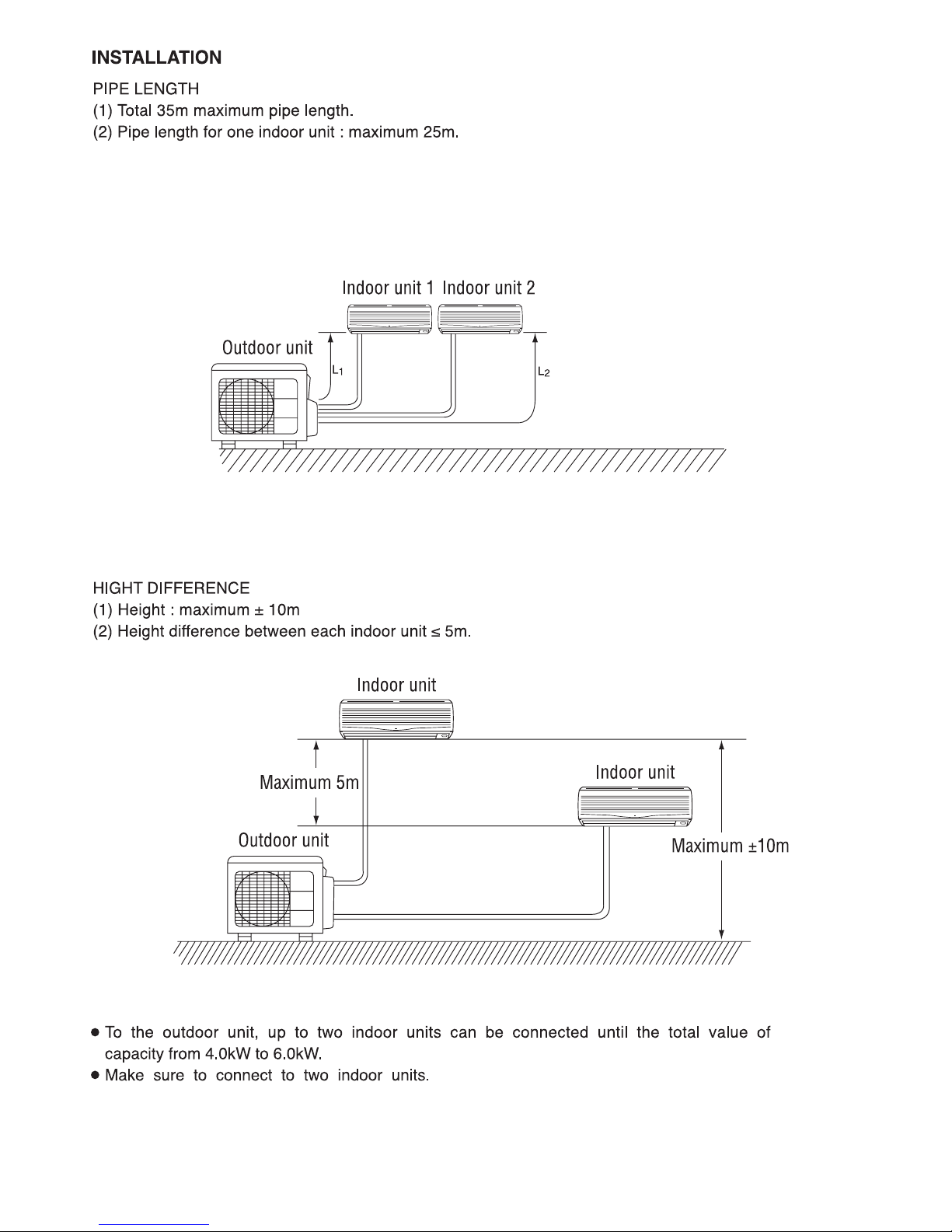
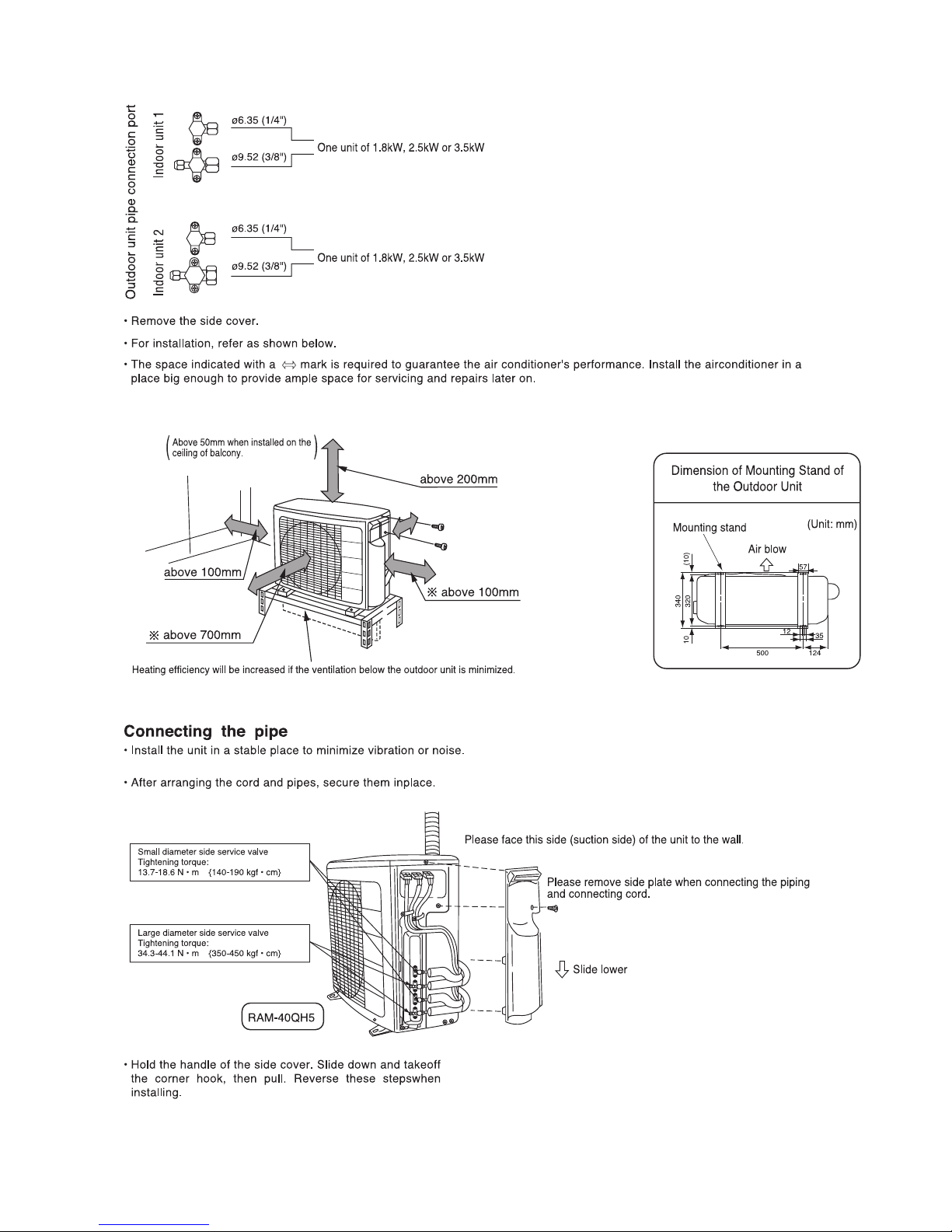
INSTALLATION ----------------------------------------------------------------------- 8
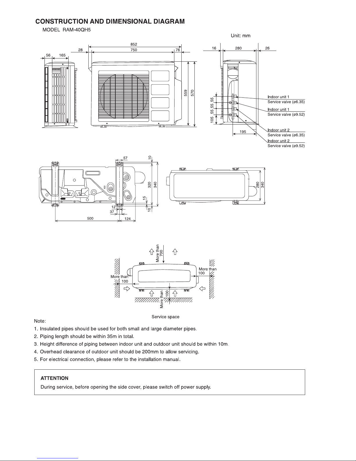
CONSTRUCTION AND DIMENSIONAL DIAGRAM --------------------- 12
MAIN PARTS COMPONENT --------------------------------------------------- 13
CAPACITY DIAGRAM ------------------------------------------------------------ 15
WIRING DIAGRAM ---------------------------------------------------------------- 20
CIRCUIT DIAGRAM --------------------------------------------------------------- 21
BLOCK DIAGRAM ----------------------------------------------------------------- 25
BASIC MODE ----------------------------------------------------------------------- 27
REFRIGERATING CYCLE DIAGRAM --------------------------------------- 40
DESCRIPTION OF MAIN CIRCUIT OPERATION ----------------------- 42
TROUBLE SHOOTING ----------------------------------------------------------- 66
PARTS LIST AND DIAGRAM -------------------------------------------------- 82
RAM-40QH5
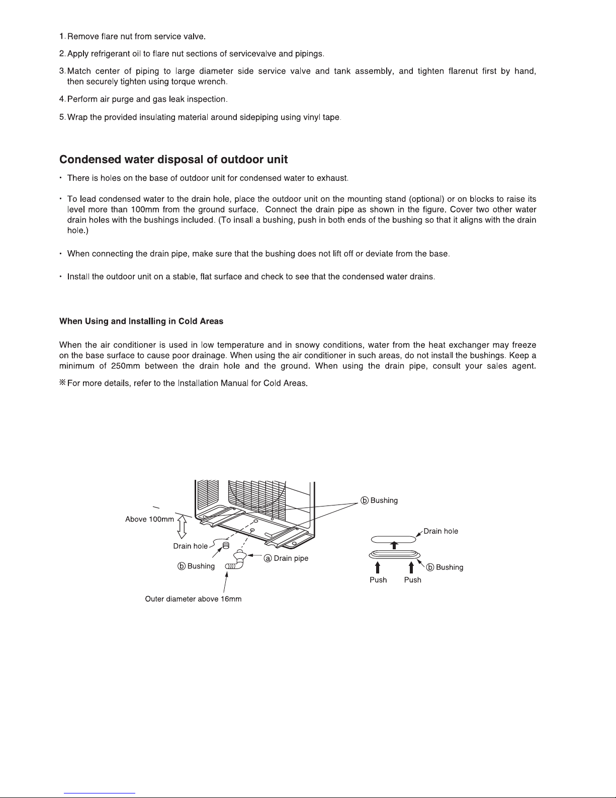
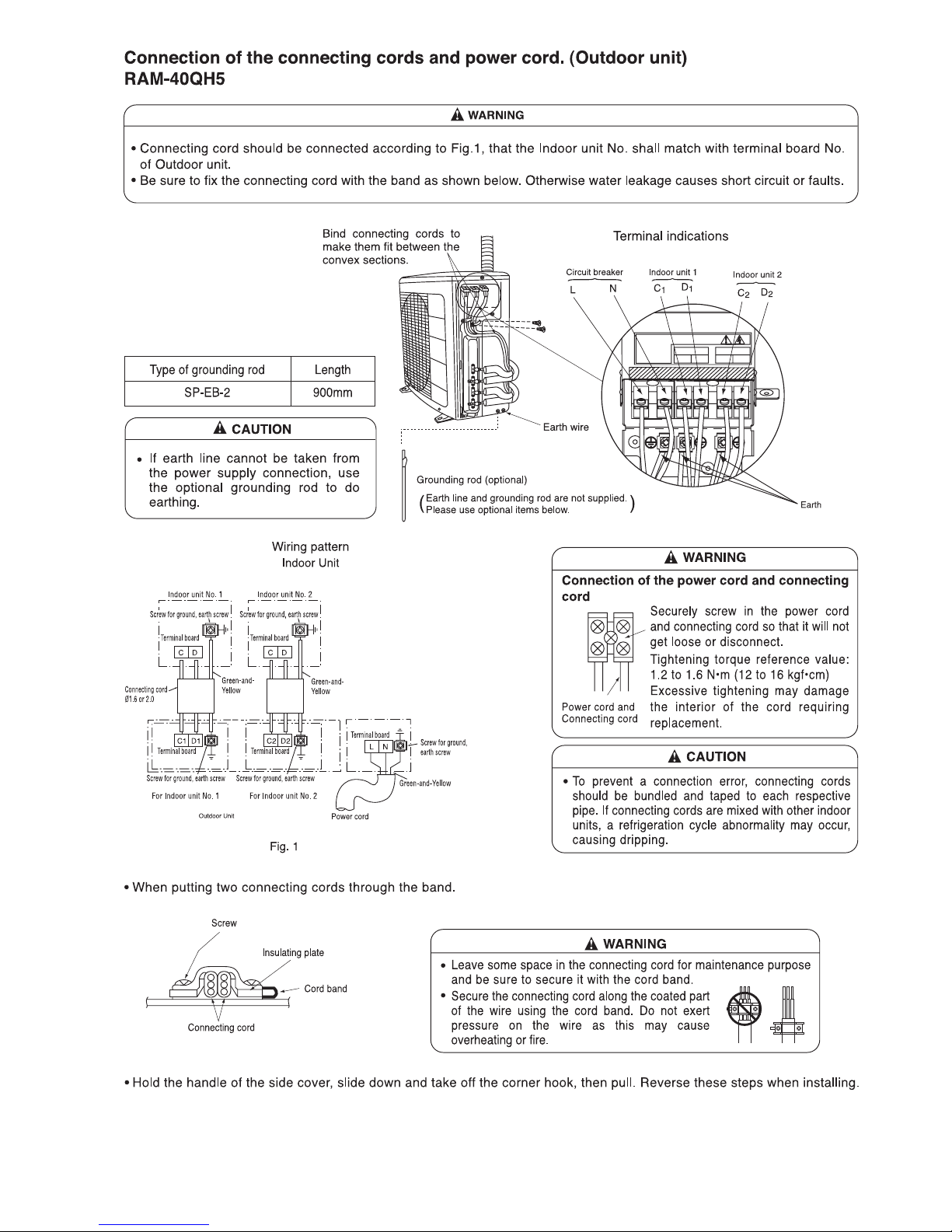
After installation
750
570
280
40
(W)
(A)
COOLING CAPACITY
DC INVERTER DUAL SYSTEM MULTI
TYPE
MODEL
POWER SOURCE
TOTAL INPUT
TOTAL AMPERES
SPECIFICATIONS
OUTDOOR UNIT
RAM-40QH5
HEATING CAPACITY
DIMENSIONS (mm)
NET WEIGHT
1ø, 220 - 240V, 50Hz
W
H
D
(kg)
(kW)
(B.T.U.)
REFER TO THE SPECIFICATIONS PAGE
– 1 –
SAFETY DURING REPAIR WORK
1. In order to disassemble and repair
the unit in question, be sure to
disconnect the power cord plug
from the power outlet before starting
the work.
2. If it is necessary to replace any parts, they should be replaced with respective genuine parts for the unit, and
the replacement must be effected in correct manner according to the instructions in the Service Manual of
the unit.
If the contacts of electrical parts
are defective, replace the
electrical parts without trying to
repair them.
3. After completion of repairs, the initial state
should be restored.
4. Lead wires should be connected and laid as
in the initial state.
5. Modification of the unit by user himself should
absolutely be prohibited.
6. Tools and measuring instruments for use in repairs or inspection should be accurately calibrated in advance.
7. In installing the unit having been repaired, be careful to prevent the occurence of any accident such as
electrical shock, leak of current, or bodily injury due to the drop of any part.
8. To check the insulation of the unit, measure the insulation resistance between the power cord plug and
grounding terminal of the unit. The insulation resistance should be 1M
or more as measured by a 500V
DC megger.
9. The initial location of installation such as window, floor or the other should be checked for being and safe
enough to support the repaired unit again.
If it is found not so strong and safe, the unit should be installed at the initial location reinforced or at a new
location.
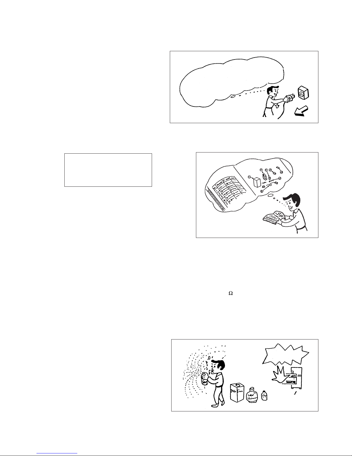
10. Any inflammable thing should never
be placed about the location of
installation.
11. Check the grounding to see whether
it is proper or not, and if it is found
improper, connect the grounding
terminal to the earth.
DANGER
First, I must disconnect
the power cord plug
from the power outlet.
– 2 –
WORKING STANDARDS FOR PREVENTING BREAKAGE OF SEMICONDUCTORS
1. Scope
The standards provide for items to be generally observed in carrying and handling semiconductors in relative
manufacturers during maintenance and handling thereof. (They apply the same to handling of abnormal goods
such as rejected goods being returned).
2. Object parts
(1) Micro computer
(2) Integrated circuits (IC)
(3) Field-effect transistors (FET)
(4) P.C. boards or the like on which the parts mentioned in (1) and (2) of this paragraph are equipped.
3. Items to be observed in handling
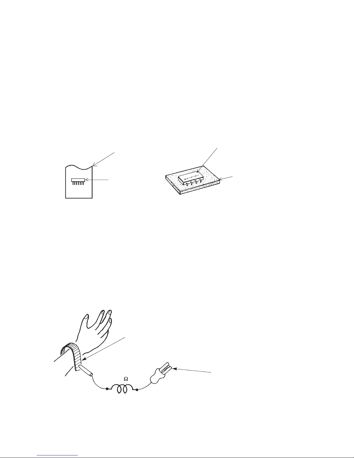
(1) Use a conductive container for carrying and storing of parts. (Even rejected goods should be handled in
the same way).
Fig. 1. Conductive Container
(2) When any part is handled uncovered (in counting, packing and the like), the handling person must always
use himself as a body earth. (Make yourself a body earth by passing one M ohm earth resistance through
a ring or bracelet).
(3) Be careful not to touch the parts with your clothing when you hold a part even if a body earth is being
taken.
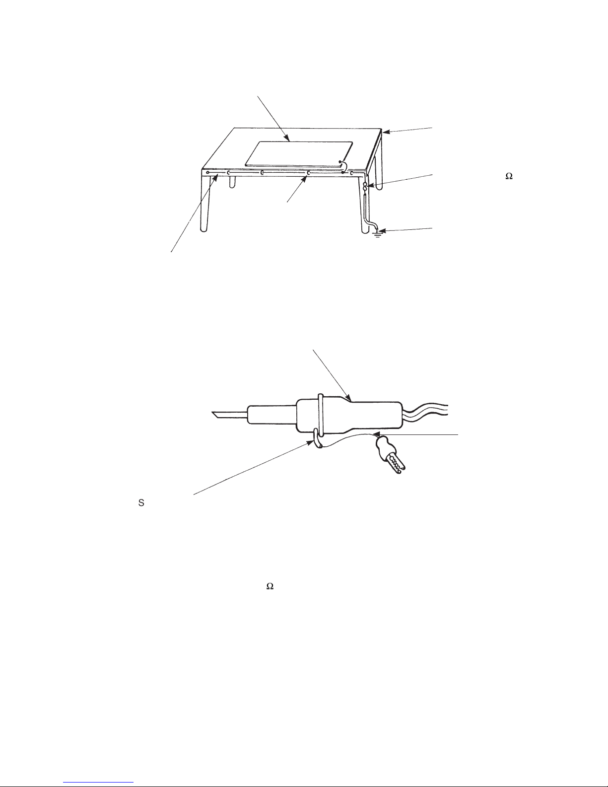
(4) Be sure to place a part on a metal plate with grounding.
(5) Be careful not to fail to turn off power when you repair the printed circuit board. At the same time, try
to repair the printed circuit board on a grounded metal plate.
1M
Fig. 2. Body Earth
Body earth
(Elimik conductive band)
Clip for connection with a
grounding wire
IC
A conductive polyvinyl bag
IC
Conductive sponge
– 3 –
(6) Use a three wire type soldering iron including a grounding wire.
Bare copper wire (for body earth)
Working
table
Resistor of 1 M (1/2W)
Earth wire
Fig. 3. Grounding of the working table
2
Screw stop at the screwed
part using a rag plate
Soldering iron
Grounding
wire
Fig. 4. Grounding a soldering iron
Use a high insulation mode (100V, 10M or higher) when ordinary iron is to be used.
(7) In checking circuits for maintenance, inspection or some others, be careful not to have the test probes of the
measuring instrument shortcircuit a load circuit or the like.
Metal plate (of aluminium, stainless steel, etc.)
Staple

– 4 –
1. In quiet operation or stopping the running, slight flowing noise of refrigerant in the refrigerating cycle is
heard occasionally, but this noise is not abnormal for the operation.
2. When it thunders near by, it is recommend to stop the operation and to disconnect the power cord plug
from the power outlet for safety.
3. The room air conditioner does not start automatically after recovery of the electric power failure for
preventing fuse blowing. Re-press START/STOP button after 3 minutes from when unit stopped.
4. If the room air conditioner is stopped by adjusting thermostat, or missoperation, and re-start in a moment,
there is occasion that the cooling and heating operation does not start for 3 minutes, it is not abnormal
and this is the result of the operation of IC delay circuit. This IC delay circuit ensures that there is no
danger of blowing fuse or damaging parts even if operation is restarted accidentally.
5. This room air conditioner should not be used at the cooling operation when the outside temperature is
below –10°C (14°F).
6. This room air conditioner (the reverse cycle) should not be used when the outside temperature is below
–15°C (5°F).
If the reverse cycle is used under this condition, the outside heat exchanger is frosted and efficiency falls.
7. When the outside heat exchanger is frosted, the frost is melted by operating the hot gas system, it is not
trouble that at this time fan stops and the vapour may rise from the outside heat exchanger.
!
CAUTION

– 5 –
SPECIFICATIONS
MODEL
FAN MOTOR
FAN MOTOR CAPACITOR
FAN MOTOR PROTECTOR
COMPRESSOR
COMPRESSOR MOTOR CAPACITOR
OVERLOAD PROTECTOR
OVERHEAT PROTECTOR
FUSE (for MICROPROCESSOR)
POWER RELAY
POWER SWITCH
TEMPORARY SWITCH
SERVICE SWITCH
TRANSFORMER
VARISTOR
NOISE SUPPRESSOR
THERMOSTAT
REMOTE CONTROL SWITCH (LIQUID CRYSTAL)
40 W
NO
NO
NO
YES
YES
5.0A
G4A
NO
NO
YES
NO
450NR
YES
YES(IC)
NO
1600g
WITHOUT REFRIGERANT BECAUSE
COUPLING IS FLARE TYPE.
UNIT
PIPES
REFRIGERANT CHARGING
VOLUME
(Refrigerant 410A)
RAM-40QH5
JU1013D2
MAX. 35m
RAM-40QH5
Additional charge of refrigerant is not required.
– 6 –
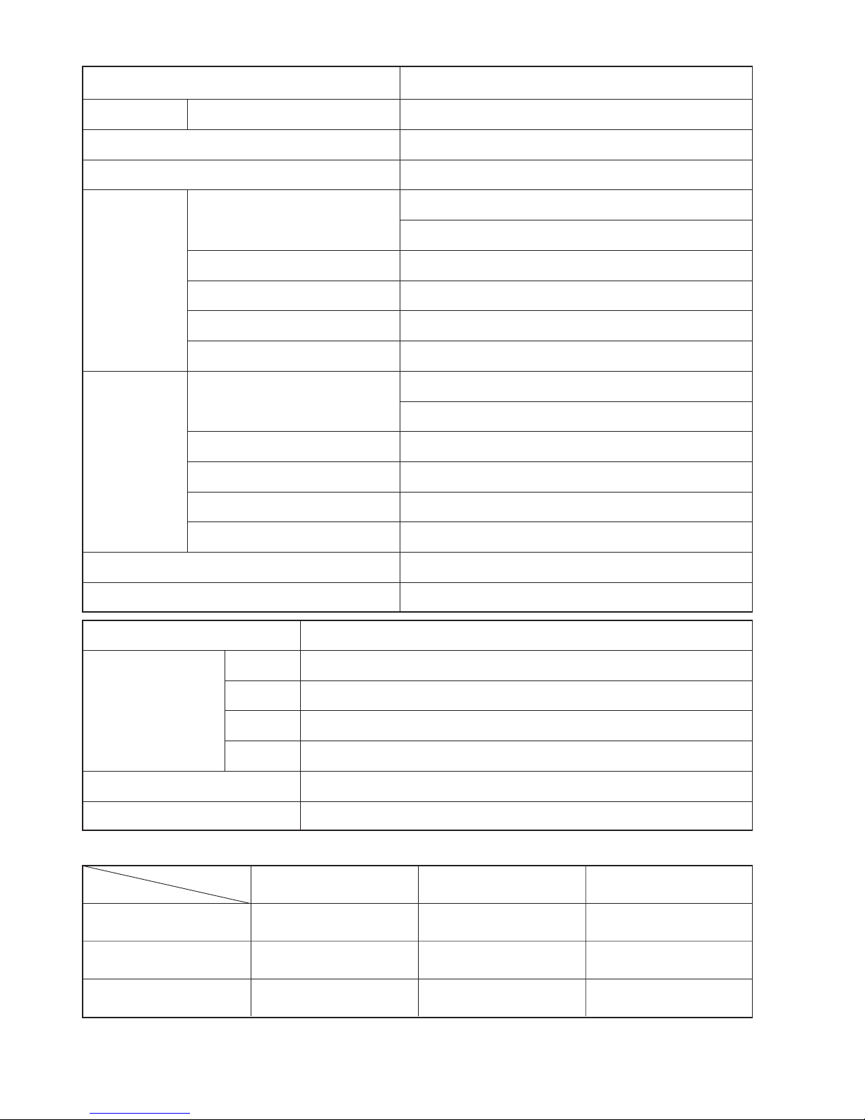
SPECIFICATIONS FOR INDOOR UNITS COMBINATION
OPERATION SCOPE
TYPE
DC INVERTER DUAL SYSTEM MULTI COOLING AND HEATING
MODEL OUTDOOR UNIT
PHASE/VOLTAGE/FREQUENCY
CIRCUIT AMPERES TO CONNECT (A)
COOLING
(TWO UNITS)
CAPACITY (kW)
(B.T.U./h)
TOTAL INPUT (W)
EER (B.T.U./hW)
TOTAL AMPERES (A)
POWER FACTOR (%)
HEATING
(TWO UNITS)
CAPACITY (kW)
(B.T.U./h)
TOTAL INPUT (W)
EER (B.T.U./hW)
TOTAL AMPERES (A)
POWER FACTOR (%)
MAXIMUM LENGTH OF PIPING
STANDARD
RAM-40QH5
1ø, 220 - 240V, 50Hz
16
4.0 (1.50 - 4.50)
13,660 (5,120 - 15,360)
1,245 (200 - 1,800)
10.97
5.72 - 5.24
99
5.0 (1.50 - 5.60)
17,070 (5,120 - 19,120)
1,350 (200 - 1,780)
12.64
6.20 - 5.68
99
MAX. 35m (TWO UNIT TOTAL)
CE (EMC&LVD)
RAM-40QH5
MODEL
W
PACKING
(mm)
H
D
cu.ft.
905
633
394
8.27
43
GROSS WEIGHT (kg)
6.35D/9.52DX2
FLARE NUT SIZE (SMALL/LARGE)
INDOOR SUCTION
TEMPERATURE (˚C)
COOLING OPERATION SCOPE
OUTDOOR SUCTION
TEMPERATURE (˚C)
INDOOR SUCTION
HUMIDITY (%)
DEHUMIDIFYING
OPERATION
HEATING OPERATION
SCOPE
16 - 32 22 - 41 BELOW 80
16 - 32 22 - 42 BELOW 80
BELOW 27 –15 - 23 —
– 7 –
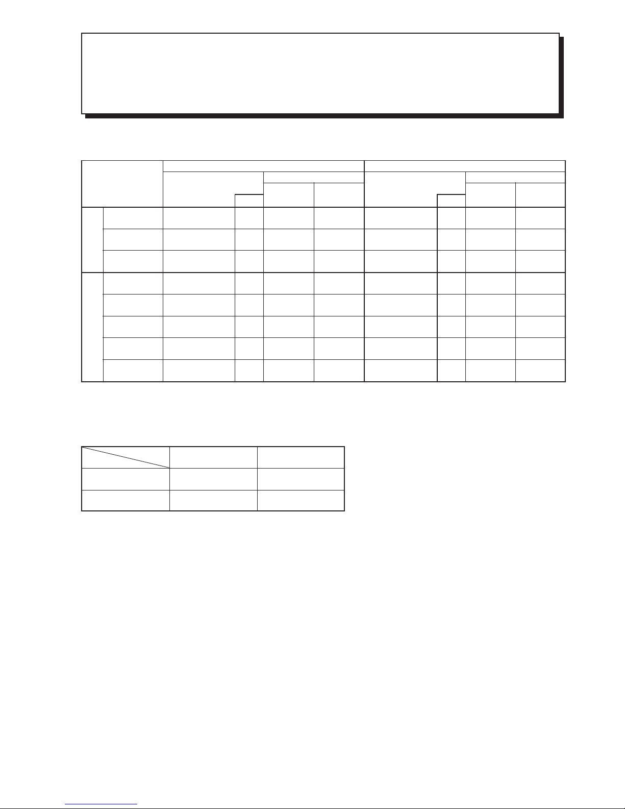
DUAL SYSTEM MULTI R.A.C.
RAM-40QH5
COOL / HEAT CAPACITY SPEC. FOR INDOOR UNITS
COMBINATIONS TO BE ABLE TO OPERATE SIMULTANEOUSLY
Whichever indoor units are installed, cooling and heating capacity depends on how many and which indoor units
are operating at that time.
RATING CONDITON (DRY BLUB / WET BULB)
COOLING
HEATING
INDOOR OUTDOOR
27 / 19 ˚C
20 / –˚C
35 / –˚C
7 / 6˚C
POSSIBLE
COMBINATIONS
TO OPERATE
CAPACITY RATING
(kW)
(RANGE)
POWER
CONSUMPTION
(W)
AMPERE (A)
at 230V
OUTDOOR UNIT
C O O L I N G
CAPACITY RATING
(kW)
(RANGE)
POWER
CONSUMPTION
(W)
AMPERE (A)
at 230V
OUTDOOR UNIT
H E A T I N G
ONE UNIT
TWO UNIT
1.8
2.5
3.5
1.8+1.8
1.8+2.5
2.5+2.5
1.8+3.5
2.5+3.5
1.8
(1.00-2.50)
2.5
(1.00-3.10)
3.5
(1.00-4.00)
1.8+1.8
(1.50-4.00)
1.70+2.30
(1.50-4.50)
2.00+2.00
(1.50-4.50)
1.60+2.40
(1.50-4.50)
1.80+2.20
(1.50-4.50)
560
(200-750)
750
(200-880)
1090
(200-1300)
1190
(200-1680)
1245
(200-1720)
1245
(200-1800)
1245
(200-1800)
1245
(200-1800)
2.5
3.3
4.8
5.2
5.5
5.5
5.5
5.5
2.5
(1.10-3.20)
3.4
(1.10-4.40)
4.2
(1.10-5.0)
2.25+2.25
(1.50-5.20)
2.20+2.60
(1.50-5.40)
2.50+2.50
(1.50-5.60)
1.70+3.30
(1.50-5.60)
2.00+3.00
(1.50-5.60)
690
(200-970)
870
(200-1120)
1080
(200-1300)
1100
(200-1480)
1240
(200-1750)
1350
(200-1780)
1350
(200-1780)
1350
(200-1780)
3.0
3.8
4.7
4.8
5.4
5.9
5.9
5.9
ONE UNIT : The values indicated are only for one unit operation when two indoor units are connected.
TOTAL
1.8
2.5
3.5
3.6
4
4
4
4
TOTAL
2.5
3.4
4.2
4.5
4.8
5
5
5
– 8 –
– 9 –
MODEL: RAM-40QH5
– 10 –
– 11 –
AC 220V~240V ONLY
LN
INDOOR 1
C1
D1
C2 D2
INDOOR 2
– 12 –
– 13 –
MAIN PARTS COMPONENT
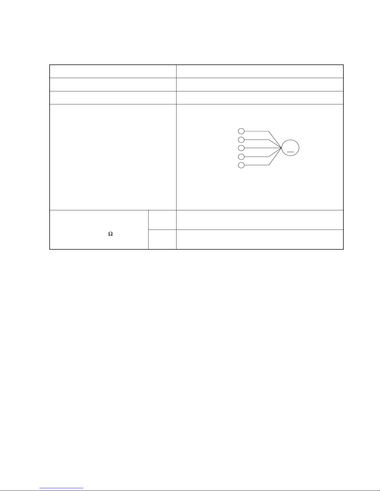
FAN MOTOR
Fan Motor Specifications
CONNECTION
MODEL
POWER SOURCE
OUTPUT
BLU : BLUE YEL : YELLOW BRN : BROWN WHT : WHITE
GRY : GRAY ORN : ORANGE GRN : GREEN RED : RED
BLK : BLACK PNK : PINK VIO : VIOLET
RAM-40QH5
DC : 360V
40W
RESISTANCE VALUE
( )
20˚C
(68˚F)
75˚C
(167˚F)
—
—
M
RED
BLK
WHT
YEL
BLU
(Control circuit built in)
360V
15V
0V
0-6V
0-15V
– 14 –
MODEL
COMPRESSOR MODEL
PHASE
RATED VOLTAGE
RATED FREQUENCY
POLE NUMBER
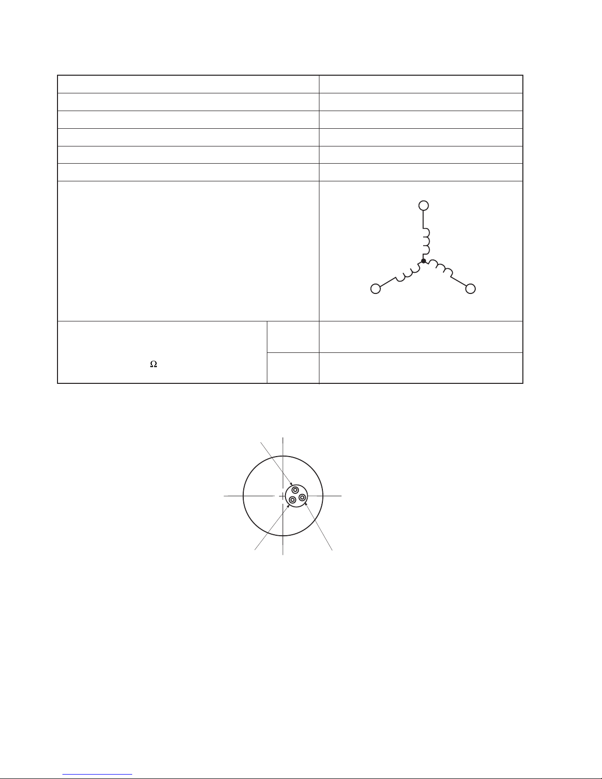
COMPRESSOR
Compressor Motor Specifications
CONNECTION
25°C
(68°F)
75°C
(167°F)
(
)
RESISTANCE VALUE
2M = 1.063
2M = 1.268
RAM-40QH5
JU1013D2
SINGLE
DC: 280-330V
50Hz
4
(U)
(V)
(W)
M
M
M
WHITE
YELLOW
RED
WHITE
RED
YELLOW
– 15 –
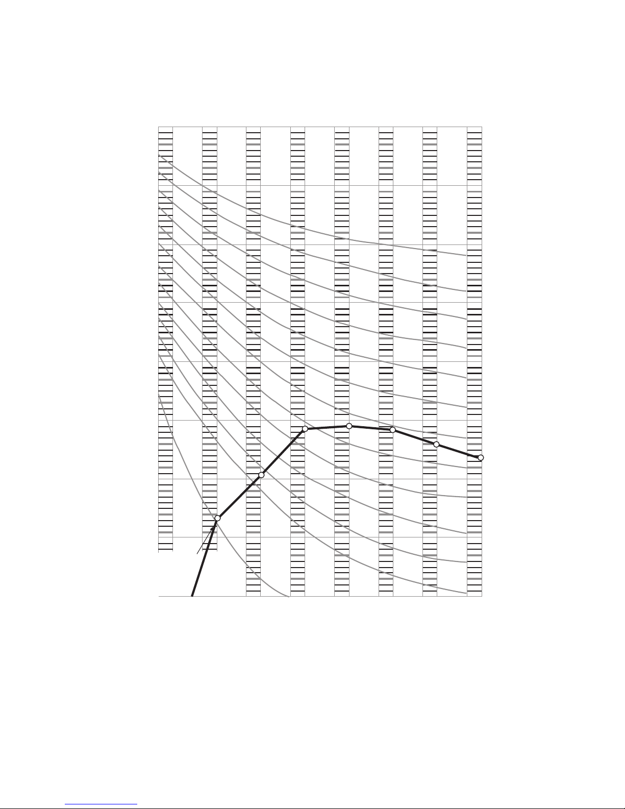
CAPACITY DIAGRAM (RELATED TO THE AMBIENT TEMPERATURE)
MODEL : RAM-40QH5
7
6
5
3.8
4.01
4.12
RATING
CAPACITY
COOLING CAPACITY (KW)
INPUT (W)
4.00
3.72
735
1050
1208
1245
1332
4
3
2
1
0
20 25 30 35
40 45
0
1000
2000
3000
COOLING CAPACITY (ROOM TEMPERATURE 27°C)
WHEN TWO INDOOR UNITS OPERATE
– 16 –
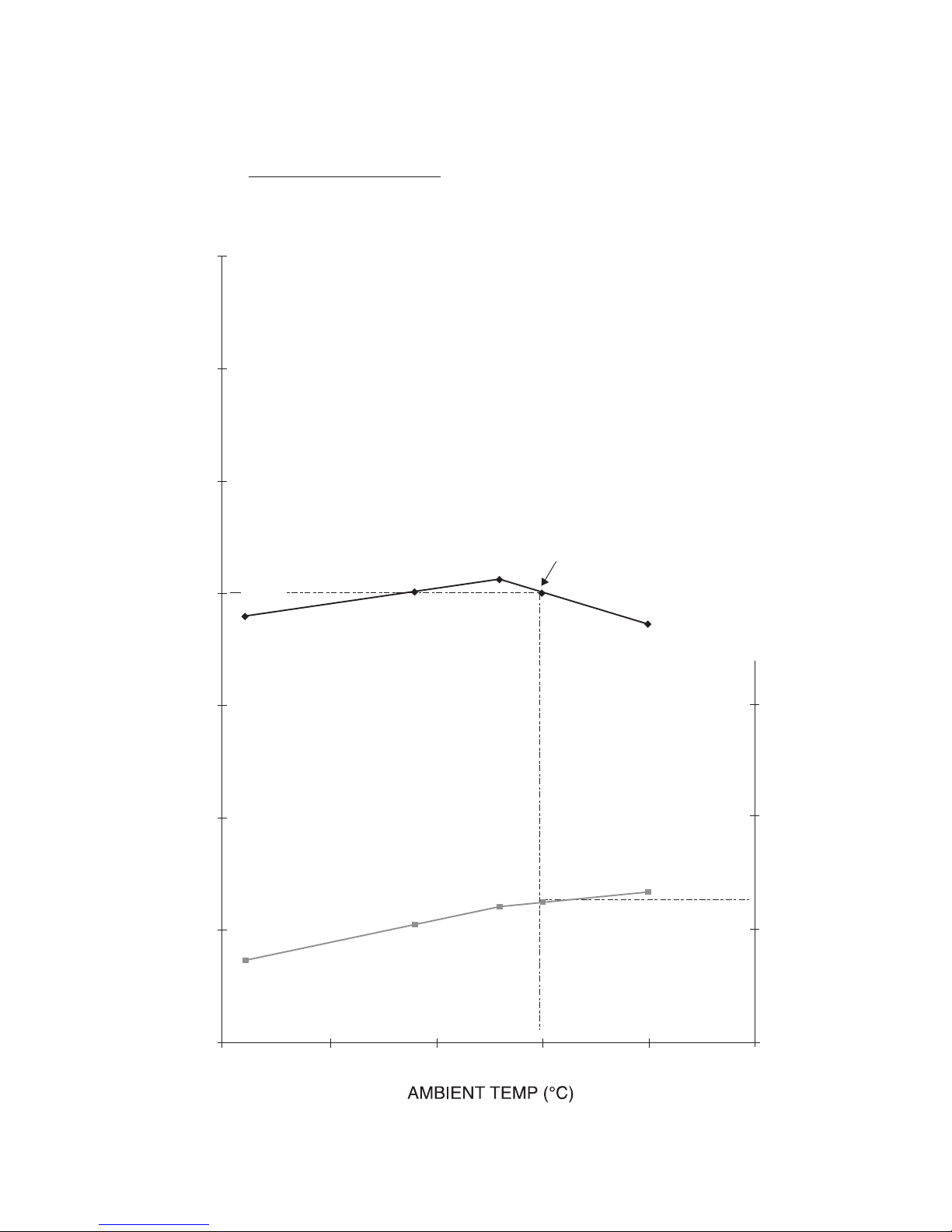
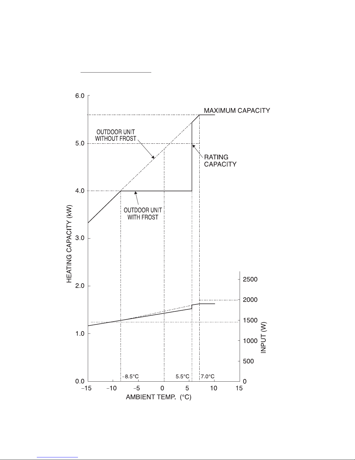
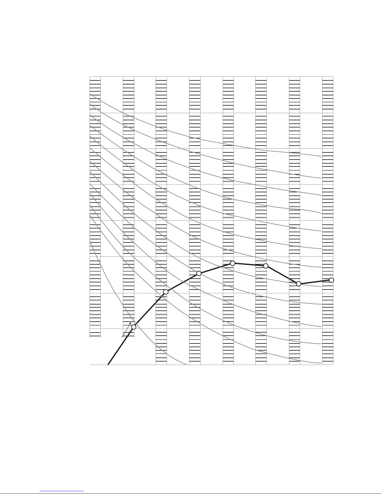
CAPACITY DIAGRAM (RELATED TO THE AMBIENT TEMPERATURE)
MODEL : RAM-40QH5
HEATING CAPACITY (ROOM TEMPERATURE 20°C)
WHEN TWO INDOOR UNITS OPERATE
– 17 –
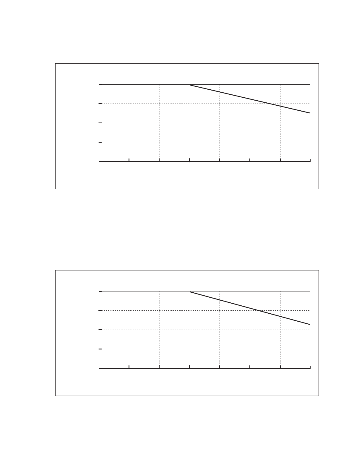
CAPACITY DIAGRAM (RELATED TO THE PIPING LENGTH)
MODEL : RAM-40QH5
1. 0
0. 9
0. 8
0. 7
0. 6
0 5 10 20 3025 3515
PIPING LENGTH (m)
CHANGE RATIO OF
CAPACITY
HEATING
1. 0
0. 9
0. 8
0. 7
0. 6
0 5 10 20 3025 3515
PIPING LENGTH (m)
CHANGE RATIO OF
CAPACITY
COOLING
– 18 –
SOUND PRESSURE LEVEL
MODEL : RAM-40QH5 (Heating)
90
NC-70
NC-60
NC-50
NC-40
NC-30
NC-20
80
70
60
50
40
Sound pressure Level [dB]
30
20
10
63
Octave band Main wavelength [Hz]
125 250 500 1000 2000 4000 8000
APPROXIMATE
THRESHOLD HEARING
FOR CONTINUROUS
NOISE
– 19 –
SOUND PRESSURE LEVEL
MODEL : RAM-40QH5 (Cooling)
90
NC-70
NC-60
NC-50
NC-40
NC-30
NC-20
80
70
60
50
40
Sound pressure Level [dB]
30
20
10
63
APPROXIMATE
THRESHOLD HEARING
FOR CONTINUROUS
NOISE
Octave band Main wavelength [Hz]
125 250 500 1000 2000 4000 8000
– 20 –
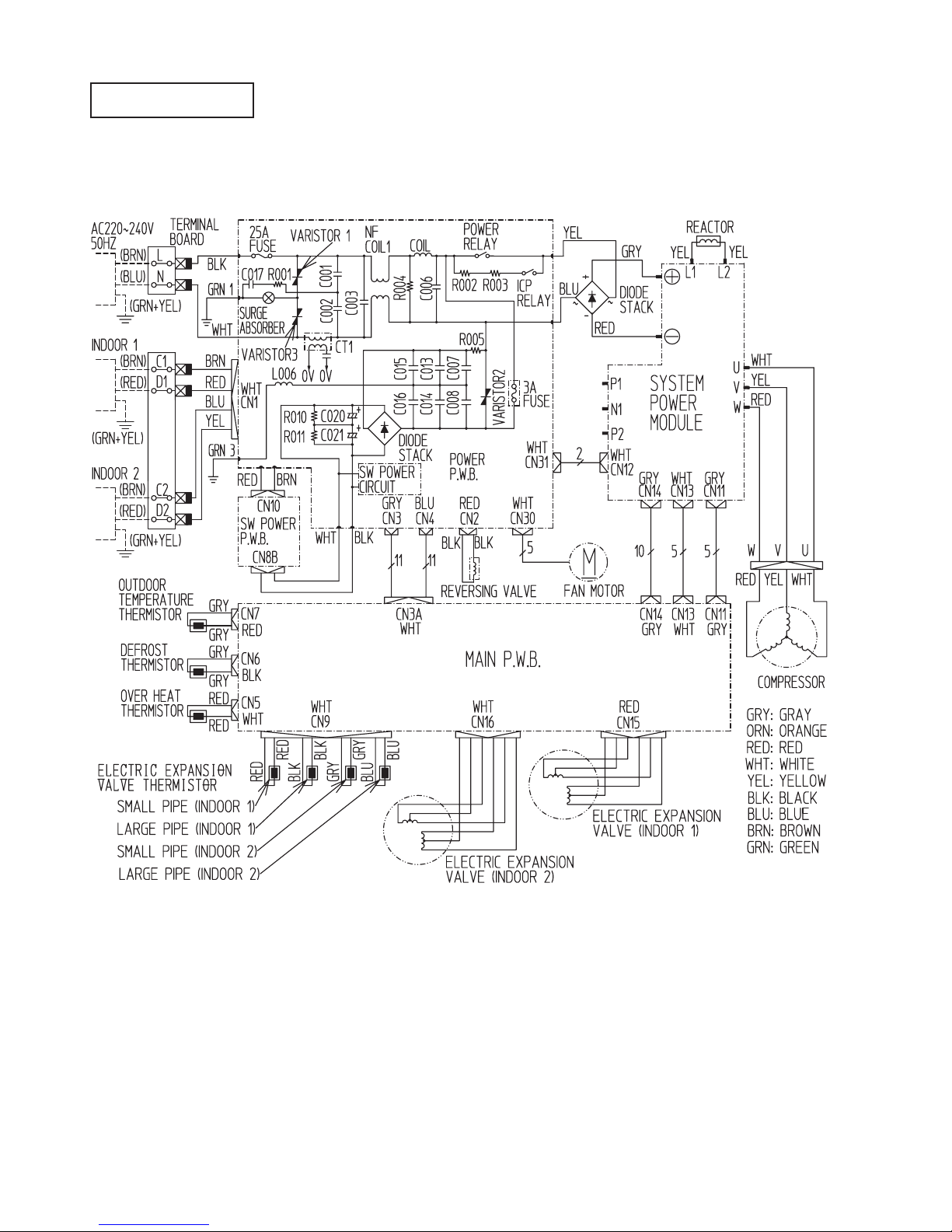
MODEL RAM-40QH5
WIRING DIAGRAM
OUTDOOR UNIT
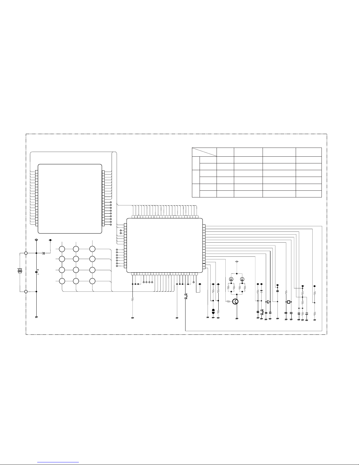
Remote Control
CIRCUIT DIAGRAM
– 21 –
1
2
3
4
5
6
7
8
10
11
13
14
15
16
17
19
20
9
12
18
SEG19
SEG18
SEG17
SEG16
SEG21
SEG24
SEG25
SEG26
SEG27
SEG28
NC
NC
NC
NC
NC
NC
NC
NC
NC
SEG20
SEG5
SEG0
SEG1
SEG2
SEG3
SEG4
SEG5
SEG6
SEG7
COM3
COM2
COM1
COM0
SEG14
SEG13
SEG12
SEG11
SEG13
SEG9
SEG8
40
39
38
37
36
35
34
33
31
30
28
27
26
25
24
22
21
32
29
23
40
39
38
37
36
35
34
33
31
30
28
27
26
25
32
29
64
63
62
61
60
59
58
57
56
55
54
53
52
51
50
49
48 47
46
45
44
43
41
42
65
66
67
68
69
70
71
72
74
75
77
78
79
80
73
76
1
2
3
4
5
6
7
8
9
10
11
12
13
14
15
16
17 18
19
20
21
22
24
23
SEG20
SEG21
SEG22
SEG23
SEG24
SEG25
SEG26
SEG27
SEG28
SEG29
SEG30
SEG31
SEG32
SEG33
SEG34
SEG35
SEG19
SEG18
SEG17
SEG16
SEG15
SEG14
SEG13
SEG12
SEG11
SEG10
SEG9
SEG8
SEG7
SEG6
SEG5
SEG4
SEG3
SEG2
SEG1
SEG0
SEG43
SEG42
SEG41
SEG40
P40
P41
P42
P43
P00
P01
P02
P03
P10
P11
P12
P13
D0
D1
D2
D3
D4
D5
D6
D7
D8
D9
BEEP
P20
P30
P31
NCVL C1
VL C2
VL C3
XC IN
XC OUT
VDD
X OUT
X IN
RESET
CARR
P23
P22
P21
VSS
IC 1
M3455OM6A-504FP
LCD 1
C8
50v/1u
K 1
D3
RB425D(1/2)
K2K3
K4
K5
P10
P11
P12
K6
K7 K8
K8 K10
K11K12
K18
K17
K15 K16
K13 K14
D0
D1
D2
D3
R1
100k
SW1
R2
P
100k
R3
100k
R4
100k
R5
Q1
2SC3443
or 2SC2982
R6
R7
R9
D2D1
D1 D2
EL-1L7
D3
(1/2)
RB425D
R10
12M
K19
X1
C9
R11
R15
R16
R13
R14
910kHz
105
104
104
150k
X2
kHz
C4
C5
C6
C7
18p
22p
R12
220k
220K
220k
100k
100k
32.768
C1
C2
C3
220p
220p
334
R6 R9
24(1/8W)
R8
330
SW-187-2P
Key matrix table
Input
D3D2D1
D0
Output
Door open Automatic swingFan speed selectionOperation selectionStart/Stop
Door shut ––Super silent coolingStart/Stop
Door open Day
• present timeHour downHour upOn timer
Door shut Super coolingRoom temperature downRoom temperature up–
Door open CancelReservation–Off timer
Door shut –––Sleep
P10
P11
P12

PRINTED WIRING BOARD LOCATION DIAGRAM
MODEL RAM-40QH5
– 23 –
MOUNTING
PCB SET
TYPE
– 25 –
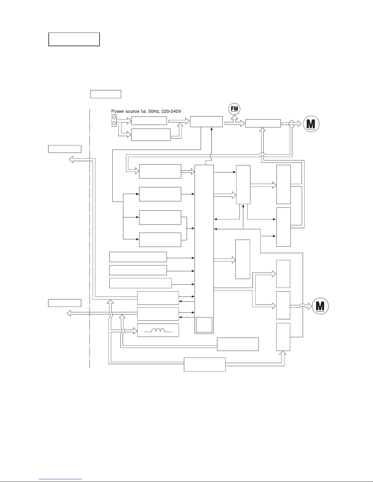
MODEL RAM-40QH5
BLOCK DIAGRAM
OUTDOOR
OUTDOOR
MODEL RAM-40QH5
Indoor Unit 1
L
C1
D1
N
Magnetic relay
Rotor pole position
desition detector
Peak current cut off
circuit
Overload external
judgement circuit
Voltage amplification
circuit
Peak current
cut off
Electric
expansion valve
Power circuit
(For Indoor 2 P.W.B)
Power circuit
(Indoor and outdoor P.W.B)
Clock
circuit
Over heat thermistor
Defrost thermistor
Reversing valve coil
DC35V
C2
D2
Indoor Unit 2
Indoor / Outdoor
interface circuit 1
Indoor / Outdoor
interface circuit 2
Outdoor temperature thermistor
PAM Power
circuit
Outdoor fan motor
Power module
Trip signal
synthesis circuit
Upper arm drive
circuit
Lower arm drive
circuit
Relay drive
circuit
Relay circuit
Electric Expansion
valve drive circuit
Self-diagnosis
circuit
Outdoor micro computer (6M01)
DC compressor
motor
Inrush current
Protection circuit
 Loading...