

Page 1
SM0174
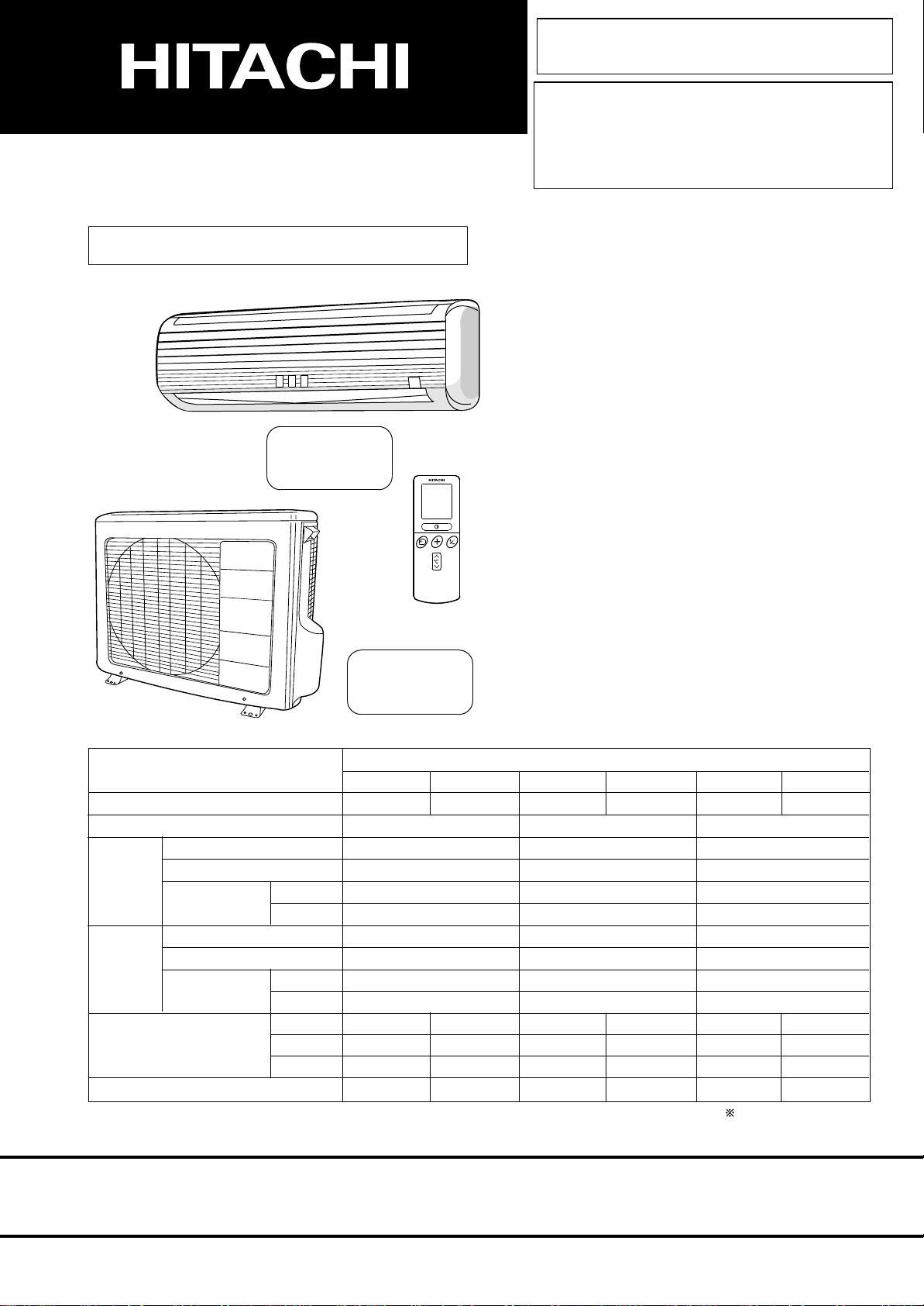
RAK25NH4 RAC25NH4
RAK35NH4 RAC35NH4
SERVICE MANUAL
TECHNICAL INFORMATION
FOR SERVICE PERSONNEL ONLY
RAK-25NH4
RAK-35NH4
RAK-50NH4
RAC-25NH4
RAC-35NH4
RAC-50NH4
RAK50NH4 RAC50NH4
REFER TO THE FOUNDATION MANUAL
CONTENTS
SPECIFICATIONS ------------------------------------------------------------------- 5
CONSTRUCTION AND DIMENSIONAL DIAGRAM --------------------- 6
MAIN PARTS COMPONENT --------------------------------------------------- 8
WIRING DIAGRAM ---------------------------------------------------------------- 10
CIRCUIT DIAGRAM --------------------------------------------------------------- 12
PRINTED WIRING BOARD LOCATION DIAGRAM ---------------------
BLOCK DIAGRAM ----------------------------------------------------------------- 20
BASIC MODE ----------------------------------------------------------------------- 22
REFRIGERATING CYCLE DIAGRAM --------------------------------------- 35
AUTO SWING FUNCTION ------------------------------------------------------ 37
DESCRIPTION OF MAIN CIRCUIT OPERATION ----------------------- 38
SERVICE CALL Q & A ---------------------------------------------------------- 69
TROUBLE SHOOTING ----------------------------------------------------------- 72
PARTS LIST AND DIAGRAM ------------------------------------------------- 92
18
SPECIFICATIONS
TYPE
MODEL
POWER SOURCE
TOTAL INPUT
COOLING
HEATING
DIMENSIONS
(mm)
NET WEIGHT
TOTAL AMPERES
CAPACITY
TOTAL INPUT
TOTAL AMPERES
CAPACITY
(W)
(A)
(kW)
(B.T.U./h)
(W)
(A)
(kW)
(B.T.U./h)
W
H
D
(kg)
INDOOR UNIT
RAK-25NH4 RAC-25NH4
1 PHASE, 50 Hz, 220-230V
695 (155~1,050)
2.50 (0.90 ~ 3.00)
900 (115 ~ 1,400)
3.50 (0.90 ~ 5.00)
860
285
183
9.0
OUTDOOR UNIT
3.20-3.05
8,540
4.15-4.00
11,950
750
570
280
38
DC INVERTER (WALL TYPE)
INDOOR UNIT
RAK-35NH4 RAC-35NH4
1 PHASE, 50 Hz, 220-230V
1,080 (155~1,280)
3.50 (0.90 ~ 4.00)
1,320 (115 ~ 1,920)
4.80 (0.90 ~ 6.60)
860
285
183
9.0
OUTDOOR UNIT
4.94-4.72
11,950
6.04-5.77
16,390
750
570
280
38
INDOOR UNIT
RAK-50NH4 RAC-50NH4
1 PHASE, 50 Hz, 220-230V
1,780 (155~2,200)
5.00 (0.90 ~ 5.20)
1,970 (115 ~ 2,100)
6.50 (0.90 ~ 8.10)
860
285
183
9.0
OUTDOOR UNIT
8.17-7.82
17,070
9.04-8.65
22,200
850
650
298
60
After installation
SPECIFICATIONS AND PARTS ARE SUBJECT TO CHANGE FOR IMPROVEMENT
ROOM AIR CONDITIONER
MAY 2003
Refrigeration & Air-Conditioning Division
INDOOR UNIT + OUTDOOR UNIT
Page 2
FOR SERVICE PERSONNEL ONLY
●
Carefully read through the procedures of proper
installation before starting installation work.
●
The sales agent should inform customers regarding
the correct operation of installation.
SPLIT UNIT AIR CONDITIONER
INSTALLATION MANUAL
Outdoor Unit RAC-35NH4
HFC
R410A
SAFETY PRECAUTION
●
Read the safety precautions carefully before operating the unit.
●
The contents of this section are vital to ensure safety. Please pay special attention to the following sign.
WARNING ........ Incorrect methods of installation may cause death or serious injury.
!
!
CAUTION ......... Improper installation may result in serious consequence.
Be sure that the unit operates in proper condition after installation. Explain to customer the proper way of operating
the unit as described in the user’s guide.
RAC-25NH4
RAC-50NH4
Tools Needed For Installation Work
●
+ – Screwdriver
●
Saw ● ø 65mm Power Drill ● Hexagonal Wrench
Key ( 4mm)
●
Gas Leakage Detector ● Pipe Cutter
●
Vinyl Tape ● Pliers ● Flare Tool
●
Measuring Tape
●
Wrench (14, 17, 22, 26, 27mm)
●
Knife
●
Putty
!
WARNING
●
Please request your sales agent or qualified technician to install your unit. Water leakage, short circuit or fire may occur if you
do the installation work yourself.
●
Please observe the instructions stated in the installation manual during the process of installation. Improper installation may
cause water leakage, electric shock and fire.
●
Make sure that the units are mounted at locations which are able to provide full support to the weight of the units. If not, the
units may collapse and impose danger.
●
Observe the rules and regulations of the electrical installation and the methods described in the installation manual when
dealing with the electrical work. Use power cables approved by the authorities of your country.
●
Be sure to use the specified wire for connecting the indoor and outdoor units. Please ensure that the connections are tight
after the conductors of the wire are inserted into the terminals. Improper insertion and loose contact may cause over-heating
and fire.
●
Please use the specified components for installation work. Otherwise, the units may collapse or water leakage, electric shock
and fire may occur.
●
Be sure to use the specified piping set for R-410A. Otherwise, this may result in broken copper pipes or faults.
●
When installing or removing an air conditioner, only specified refrigerant (R410A) shall be allowed, do not allow air or moisture
to remain in the refrigeration cycle. Otherwise, pressure in the refrigeration cycle may become abnormally high so that a rupture
may be caused.
●
Be sure to ventilate fully if a refrigerant gas leak while at work. If the refrigerant gas comes into contact with fire, a poisonous
gas may occur.
●
After completion of installation work, check to make sure that there is no refrigeration gas leakage. If the refrigerant gas leaks
into the room, coming into contact with fire in the fan-driven heater, space heater, etc., a poisonous gas may occur.
●
Unauthorized modifications to the air conditioner may be dangerous. If a breakdown occurs please call a qualified air conditioner
technician or electrician. Improper repairs may result in water leakage, electric shock and fire, etc.
!
CAUTION
●
A circuit breaker or fuse (16A time delay) must be installed. Without a circuit breaker or fuse the danger of electric shock exists.
A main switch with a contact gap of more than 3mm has to be installed in the power supply line to the outdoor unit.
●
Do not install the unit near a location where there is flammable gas. The outdoor unit may
catch fire if flammable gas leaks around it.
●
Please ensure smooth flow of water when installing the drain hose.
●
Piping shall be suitable supported with a maximum spacing of 1m between the supports.
<
I477: A
>
Page 3

THE CHOICE OF MOUNTING SITE (Please note the following matters and obtain permission from customer before installation).
!
WARNING
●
The Outdoor unit must be mounted at a location which can support heavy weight. Otherwise, noise and vibration will increase.
!
CAUTION
●
Do not expose the unit under direct sunshine or rain. Besides, ventilation must be good and clear of obstruction.
●
The air blown out of the unit should not point directly to animals or plants.
●
The clearances of the unit from top, left, right and front are specified in figure below. At least 3 of the above sides must be open air.
●
Be sure that the hot air blown out of the unit and noise do not disturb the neighbourhood.
●
Do not install at a location where there is flammable gas, steam, oil and smoke.
●
The location must be convenient for water drainage.
OUTDOOR UNIT
●
Place the Outdoor unit and its connecting cord at least 1m away from the antenna or signal line of television, radio or telephone. This is to
avoid noise interference.
Names of Outdoor Components
QtyNo. Item
Bush
0
(RAC-25NH4,
RAC-35NH4)
(RAC-50NH4)
2
3
Figure showing the Installation of Outdoor Unit.
Drain Pipe
!
1
Bush
#
1
Dimension of Mounting Stand
of the Outdoor unit
(unit: mm)
mounting stand
Dimension of Mounting Stand
of the Outdoor unit
(unit: mm)
mounting stand
●
Please mount the Outdoor unit on stable ground to prevent
12
35
500
12
35
508
(RAC-25NH4,
RAC-35NH4)
57
10
320
340
20
(10)
124
(RAC-50NH4)
57
10
320
340
35
(10)
198
above 100mm
above 700mm
vibration and increase of noise level.
●
Decide the location for piping after sorting out the different types
of pipe available.
●
When removing side cover, please pull the handle after undoing
the hook by pulling it downward.
Please face this side (suction
side) of the unit to the wall.
Please remove side cover
when connecting the piping
and connecting cord.
Pull downward
above 200mm
above 50mm when
installed on the
(
ceiling of balcony
CONDENSED WATER DISPOSAL OF OUTDOOR UNIT
There are holes on the base of Outdoor unit for condensed
In order to flow condensed water to the drain, the unit is installed on
At first insert one portion of the hook to the base (Portion A), then
When Using and Installing In Cold Areas
When the air conditioner is used in low temperature and in snowy
conditions, water from the heat exchanger may freeze on the base
surface to cause poor drainage. When using the air conditioner in such
areas, do not install the bushings. Keep a minimum of 250mm between
the drain hole and the ground. When using the drain pipe, consult your
sales agent.
For more details, refer to the installation Manual for Cold Areas.
● The difference in height
between the indoor and
outdoor unit should be
kept max 5m.
● The connecting pipe, no
matter big or small,
should all be insulated
with insulation pipe and
then wrapped with vinyl
tape. (The insulator will
deteriorate if it is not
wrapped with tape).
The connection of insulated
drain hose.
inner diameter ø 16mm
Maximum pipe length 20m
)
above 100mm
Please use insulated drain
hose for the indoor piping
(commercial product).
give clearance as
wide as possible
above 200mm
water to exhaust.
a stand or a block so that the unit is 100mm above the ground as
shown figure. Join the drain pipe to one hole.
pull the drain pipe in the direction shown by the arrow while inserting
the hook into the base. After installation, check whether the drain
pipe cling to the base firmly.
A
BASE
DRAIN PIPE
100 mm ABOVE
10
BUSH
12
11
DRAIN PIPE
BUSH
Page 4
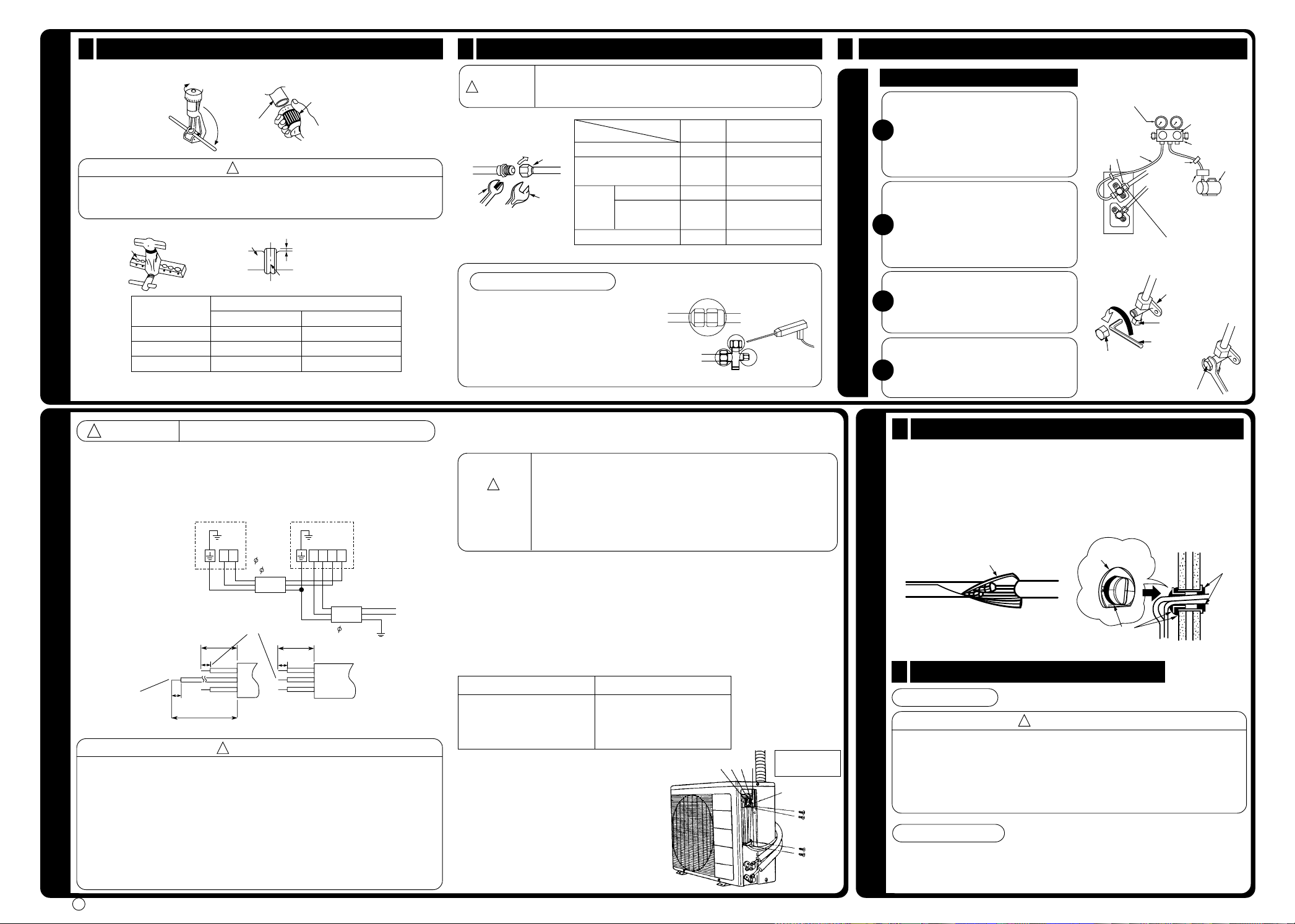
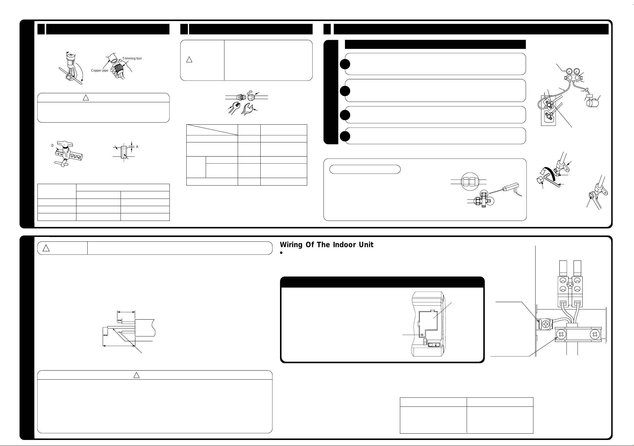
Preparation of Pipe1
●
Use a pipe cutter to cut the copper pipe.
Trimming tool
Copper pipe
!
CAUTION
●
Jagged edge will cause leakage.
●
Point the side to be trimmed downwards during trimming to prevent copper
chips from entering the pipe.
●
Before flaring, please put on the flare nut.
Die
Outer
Diameter (mm)
6.35
9.52
12.7
Die
Copper pipe
For R410A tool
0.0
0.5mm
~
0.0
0.5mm
~
0.5mm
0.0
~
A
A (mm)
●
Recommend to use
R410A flaring tool.
For R22 tool
1.0mm
1.0mm
1.0mm
INSTALLATION OF REFRIGERATING PIPES AND AIR REMOVAL
Pipe Connection2
In case of removing flare nut of an Indoor unit, first remove a nut
!
CAUTION
Wrench
Gas Leakage Inspection
Please use gas leakage detector to check if
leakage occurs at the connection of Flare
nut as shown on the right.
If gas leakage occurs, further tighten the
connection to stop leakage. (Use the detector
provided for R410A)
of small diameter side, or a seal cap of big diameter side will fly
out. Prevent water from entering into the piping when working.
Torque
wrench
Small dia. side
Large dia. side
Small dia. side
Valve
head cap
Valve core cap
Large dia. side
Flare nut
Outer
dia.of pipe
6.35 (1/4")
9.52 (3/8")
12.7 (1/2")
6.35 (1/4")
9.52 (3/8")
12.7 (1/2")
Torque N·m
(kgf · cm)
13.7 – 18.6 (140 – 190)
34.3 – 44.1 (350 – 450)
44.1 – 53.9 (450 – 550)
19.6 – 24.5 (200 ~ 250)
19.6 – 24.5 (200 ~ 250)
29.4 – 34.3 (300 – 350)
12.3 – 15.7 (125 ~ 160)
Removal Of Air From The Pipe And Gas Leakage Inspection
3
Procedures of using Vacuum Pump for Air Removal
As shown in right figure, remove the cap
of valve core. Then, connect the charge
hose. Remove the cap of valve head.
1
Connect the vacuum pump adapter to
the vacuum pump and connect the
charge hose to the adapter.
Fully tighten the “Hi” shuttle of the
When the meter reaches - 101KPa
(-76cmHg) during pumping, fully
tighten the shuttle.
Valve
Meter showing pressure
Charge hose
Lo Hi
Valve
Vacuum pump
adapter
manifold valve and completely unscrew
the “Lo” shuttle. Run the vacuum pump
2
for about 10–15 minutes, then completely
AIR REMOVAL
tighten the “Lo” shuttle and switch off
the vacuum pump.
Completely unscrew the spindle of the
service valve (at 2 places) in anti-
3
clockwise direction to allow the flow of
coolant (using Hexagonal Wrench key).
Remove the charge hose and tighten the
cap of valve head. Check the cap’s
4
periphery if there is any gas leakage.
The task is then completed.
When pumping starts, slightly loosen the
flare nut to check of air sucked in. Then
tighten the flare nut.
The body of
service valve
Cap of
valve core
Hexagonal
Cap of valve head
Wrench Key
Cap of valve head
Closed
R410A
Manifold valve
Vacuum
pump
●
WARNING
!
THIS APPLIANCE MUST BE EARTHED.
Power supply shall be connected at the rated voltage, otherwise the unit will be
broken or could not reach the specified capacity.
Procedures of Wiring
In case that power is supplied from Outdoor Unit
Indoor Unit Outdoor Unit
1.6 or
2.0
Connecting Cord
Strip wires
Outdoor
Unit
GRN + YEL
25mm
10mm
10mm
25mm
10mm
35mm
Power line Control line
!
WARNING
●
The naked part of the wire core should be 10 mm and fix it to the terminal
tightly. Then try to pull the individual wire to check if the contact is tight. Improper
CONNECTION OF POWER CORD
insertion may burn the terminal.
●
Be sure to use only power cables approved from the authorities in your country.
For example in Germany: Cable type: NYM 3x1.5mm
●
Please refer to the installation manual for wire connection to the terminals of the
units. The cabling must meet the standards of electrical installation.
●
There is a AC voltage of 230V between the L and N terminals. Therefore,
before servicing, be sure to remove the plug from the AC outlet or switch off
the main switch.
<
I477: A
>
DCNLDC
Connecting Cord
2.0
AC 220 - 230V
2
.
Wiring of The Outdoor Unit
●
Please remove the side cover for wire connection.
●
If you cannot attach the side cover due to the connecting cord,
!
WARNING
press the connecting cord in direction to the front panel to fix it.
●
Be sure that the hooks of the side cover is fixed in certainly.
Otherwise water leakage may occur and this causes short circuit
or faults.
●
The connecting cord should not touch to service valve and pipes.
(It becomes high temperature in heating operation.)
Checking for the electric source and the
voltage range
●
Before installation, the power source must be checked and necessary wiring work
must be completed. To make the wiring capacity proper, use the wire gauges list
below for the lead-in from a pole transformer and for the wiring from a switch board
of fuse box to the main switch and outdoor unit in consideration of the locked rotor
current.
IMPORTANT
Cable length
up to 16m
up to 15m
up to 25m
●
Investigate the power supply capacity and
other electrical conditions at the installation
location.
Depending on the model of room air
conditioner to be installed, request the
customer to make arrangements for the
necessary electrical work etc.
The electrical work includes the wiring work
up the outdoor. In localities where electrical
conditions are poor, use of a voltage
regulation is recommended.
Wire cross-section
2
1.5mm
2
2.5mm
2
4.0mm
CD
N
L
Use 16A Time
Delay Fuse
Earth terminal
1
Insulation And Maintenance Of Pipe Connection
●
The connected terminals should be completely sealed with heat insulator and
then tied up with rubber strap.
●
Please tie the pipe and power line together with vinyl tape as shown in the figure
showing the installation of Indoor and Outdoor units. Then fix their position with
holders.
●
To enchance the heat insulation and to prevent water condensation, please
cover the outdoor part of the drain hose and pipe with insulation pipe.
●
Completely seal any gap with putty.
Sleeve of
Insulation material for pipe connection
2
Power Source And Operation Test
protection pipe
Putty
Power Source
!
CAUTION
●
Please use a new socket. Accident may occur due to the use of old socket
because of poor contact.
●
Please plug in and then remove the plug for 2 – 3 times. This is to ensure that
the plug is completely plugged into the socket.
●
Keep additional length for the power cord and do not render the plug under
FINAL STAGE OF INSTALLATION
external force as this may cause poor contact.
●
Do not fix the power cord with U-shape nail.
Operation Test
●
Please ensure that the air conditioner is in normal operating condition during
the operation test.
●
Explain to your customer the proper operation procedures as described in the
user’s manual.
Putty
Page 5

above 50mm
above 100mm
above
0.45m
above 300mm
must not bend
above 100mm
2
7
4
5
3
9
Maximum pipe length 20m
Plug
2,300mm or more
1
!
!
!
!
FOR SERVICE PERSONNEL ONLY
!
!
0.9m
1.6m
!
Connection
Horizontally
perpendicular
to the unit
inner diameter ø 16mm
HFC
R410A
●
Carefully read through the procedures of proper
installation before starting installation work.
●
The sales agent should inform customers regarding
the correct operation of installation.
SPLIT UNIT AIR CONDITIONER
INSTALLATION MANUAL
RAK-25NH4
Indoor Unit
SAFETY PRECAUTION
●
Read the safety precautions carefully before operating the unit.
●
The contents of this section are vital to ensure safety. Please pay special attention to the following sign.
WARNING ........ Incorrect methods of installation may cause death or serious injury.
CAUTION ......... Improper installation may result in serious consequence.
Be sure that the unit operates in proper condition after installation. Explain to customer the proper way of operating
the unit as described in the user’s guide.
RAK-35NH4
RAK-50NH4
Tools Needed For Installation Work
●
+ – Screwdriver
●
Saw ● ø 65mm Power Drill ● Hexagonal Wrench
Key ( 4mm)
●
Gas Leakage Detector ● Pipe Cutter
●
Vinyl Tape ● Pliers ● Flare Tool
●
Measuring Tape
●
Wrench (14, 17, 22, 26, 27mm)
●
Knife
●
Putty
●
●
●
●
●
●
●
●
●
●
●
●
●
●
●
WARNING
Please request your sales agent or qualified technician to install your unit. Water leakage, short circuit or fire may occur if you
do the installation work yourself.
Please observe the instructions stated in the installation manual during the process of installation. Improper installation may
cause water leakage, electric shock and fire.
Make sure that the units are mounted at locations which are able to provide full support to the weight of the units. If not, the
units may collapse and impose danger.
Observe the rules and regulations of the electrical installation and the methods described in the installation manual when
dealing with the electrical work. Use power cables approved by the authorities of your country.
Be sure to use the specified wire for connecting the indoor and outdoor units. Please ensure that the connections are tight
after the conductors of the wire are inserted into the terminals. Improper insertion and loose contact may cause over-heating
and fire.
Please use the specified components for installation work. Otherwise, the units may collapse or water leakage, electric shock
and fire may occur.
Be sure to use the specified piping set for R-410A. Otherwise, this may result in broken copper pipes or faults.
When installing or removing an air conditioner, only specified refrigerant (R410A) shall be allowed, do not allow air or moisture
to remain in the refrigeration cycle. Otherwise, pressure in the refrigeration cycle may become abnormally high so that a rupture
may be caused.
Be sure to ventilate fully if a refrigerant gas leak while at work. If the refrigerant gas comes into contact with fire, a poisonous
gas may occur.
After completion of installation work, check to make sure that there is no refrigeration gas leakage. If the refrigerant gas leaks
into the room, coming into contact with fire in the fan-driven heater, space heater, etc., a poisonous gas may occur.
Unauthorized modifications to the air conditioner may be dangerous. If a breakdown occurs please call a qualified air conditioner
technician or electrician. Improper repairs may result in water leakage, electric shock and fire, etc.
A circuit breaker or fuse (16A time delay) must be installed. Without a circuit breaker or fuse the danger of electric shock exists.
A main switch with a contact gap of more than 3mm has to be installed in the power supply line to the outdoor unit.
Do not install the unit near a location where there is flammable gas. The outdoor unit may
catch fire if flammable gas leaks around it.
Please ensure smooth flow of water when installing the drain hose.
Piping shall be suitable supported with a maximum spacing of 1m between the supports.
CAUTION
Page 6
above 50mm
above 100mm
above
0.45m
above 300mm
must not bend
above 100mm
2
7
4
5
3
9
Maximum pipe length 20m
Plug
2,300mm or more
1
THE CHOICE OF MOUNTING SITE (Please note the following matters and obtain permission from customer before installation).
!
!
0.9m
1.6m
!
Connection
Horizontally
perpendicular
to the unit
inner diameter ø 16mm
WARNING
●
The unit should be mounted at stable, non-vibratory location which can provide full support to the unit.
CAUTION
●
No nearby heat source and no obstruction near the air outlet is allowed.
●
The clearance distances from top, right and left are specified in figure below.
●
The location must be convenient for water drainage and pipe connection with the Outdoor unit.
●
To avoid interference from noise please place the unit and its remote controller at least 1m from the radio, television and inverter
INDOOR UNIT
type fluorescent lamp.
●
To avoid any error in signal transmission from the remote controller, please put the controller far away from high-frequency
machines and high-power wireless systems.
●
The installation height of indoor unit must be 2.3m or more in a non public area.
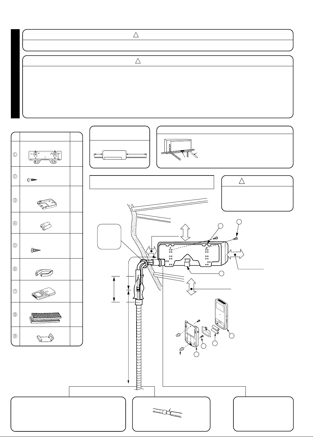
Names of Indoor Components
QtyNo. Item
Hanger
1
Screw for Hanger
2
Holder for Remote
Controller
3
AAA Size Battery
4
Screw for holder of
Remote Controller
5
Insulation pipe
6
Remote Controller
7
Purifying Filter
8
(4.1x32)
(3.1x16)
1
6
1
2
2
1
1
1
The Length of Indoor Unit
Connecting Cord
Figure showing the Installation of Indoor Unit.
Be sure to
completely
seal any
gap with
putty.
Direction of Piping
There are 4 directions allowed, namely,
horizontally perpendicular to the unit,
vertically down from right, horizontally out
from right and horizontally out to left.
Don’t form the piping downward at the
left of the unit.
CAUTION
The installation height of indoor
•
unit must be 2.3m or more in
a non public area.
Holder
9
● The difference in height between the indoor and outdoor
unit should be kept max 5m.
● The connecting pipe, no matter big or small, should all
be insulated with insulation pipe and then wrapped with
vinyl tape. (The insulator will deteriorate if it is not wrapped
with tape).
1
The connection of insulated drain hose.
Please use insulated drain hose for the
indoor piping (commercial product).
The indoor piping should be
insulated with the enclosed
insulation pipe. (If the
insulator is insufficient,
please use commercial
products).
Page 7

above 50mm
above 100mm
above
0.45m
above 300mm
must not bend
above 100mm
2
7
4
5
3
9
Maximum pipe length 20m
Plug
2,300mm or more
1
!
!
!
!
!
!
0.9m
1.6m
1
!
!
!
!
!
!
!
External dimension of
indoor unit
160mm
160mm
80mm
860mm
40mm
45mm
30mm
Drain Hose
45mm
298mm
Level
Line
Hole for
pipe
Mark
Weight
Screw for Hanger
Please use more
than 4 screws.
Hanger
32mm
20mm
ø4.8mm
ø4.4mm
Wall
1 Hanger
2 Screw
Plug
Wall
above 50mm
Ceiling
4.1 x 32 Screw
Wall
Remote
Control
Holder
5 Screw
Plug
3
Sleeve of
protection
pipe
WALL
Protection
pipe
Seal with
putty
Seal with
putty
2 ~ 5mm
OutdoorIndoor
Connecting cords,
pipe and drain hose
must be tied together
with Vinyl tape.
Hanger
Hook
Refrigerating
Pipe
Connecting
Cord
Drain Hose
Protection
Pipe
Lift the body
of the unit
upwards and
then force
it downwards.
Hanger
Projection
Screw driver
Claw of indoor unit
Circle hole
2
1
!
Drain hoseDrain cap
Drain cap
Please insert
until here
Drain hose
Please insert
until here
Pipe
support
Pull up the pipe after
bending downward
Openings
Pipe
Connecting cord
Drain hose
Insulation pipe (must be wrapped with
vinyl tape at every 120mm).
Holder
9
Insulation pipe
6
Pipe
Rubber strap tied with great force
below
5mm
Please bend at a small
radius to form an arc
about 15cm
Projection
Temporary stand
Connected
section
Holder
Connecting cord
Drain hose
Protection
pipe
Bending
upwards
Condensed
water pond
Ditch
Condensed
water pond
!
Connection
Horizontally
perpendicular
to the unit
inner diameter ø 16mm
HFC
R410A
Installation of Hanger, Wall Penetration and Installation of Protection Pipe
CAUTION
●
The draining of the water container inside the indoor unit can be done from the left.
Therefore the hanger must be fixed horizontally or slightly tilted towards the side of
drain hose. Otherwise, condensed water may overflow the water container.
Direct Mounting On The Wall
●
Please use hidden beams in the wall to hold the hanger.
Procedures of Installation and Precautions
●
Procedures to fix the hanger.
1. Drill holes on wall. 2. Push plug into the holes. 3. Fix the hanger on wall
(As shown below) (As shown below) with 4.1 x 32 screw
(As shown in figure below)
INDOOR UNIT
●
Procedures to fix the holder of remote control.
1. Drill holes on wall. 2. Push plug into the holes.
(As shown below) (As shown below)
2
Installation of the Indoor Unit
VERTICALLY DOWNWARD PIPING
Preparation
●
Connect connecting cord.
●
Pull out the pipe, connecting cord and drain hose.
Installation
●
The upper part of the Indoor unit is hanged on the hanger.
●
The projection at the lower part of the Indoor unit is hooked onto the hanger.
CAUTION
Please pull the lower part of
the Indoor unit outwards to
check if the unit is hooked
onto the hanger. Improper
installation may cause
vibration and noise.
HOW TO REMOVE INDOOR UNIT FROM HANGER
●
Pull down PULL section on the bottom of indoor
unit and pull it towards you, then claws are
released from hanger. (Indicated by 2 arrows in
the drawing on the right.)
●
When bottom face of indoor unit cannot be
pulled due to obstacles, etc. Remove front cover,
insert screw driver into circle hole, pull claws
down and pull indoor unit towards you.
●
Please check how to remove and attach front
cover in this instruction manual.
HORIZONTAL PIPING
Preparation
Change of Drain Hose and Installation Procedures.
●
Exchange the location of drain hose and drain cap during horizontal piping as shown in
figure below. Be sure to plug in the drain hose until the insulating material folds upon itself.
●
Please use pliers to pull out the drain cap.
(This is an easier way to remove the drain cap).
INSTALLATION OF REFRIGERATING PIPES AFTER CONNECTION
●
The refrigerating pipes should be adjusted to fit into
the hole on the wall and then ready for further
connection.
●
The terminals of 2 connected pipes must be covered
with insulator used for terminal connection. Then the
pipes are wrapped with insulation pipe.
●
Connect the connecting cord after removing electrical
cover. (Refer to “CONNECTION OF POWER CORD”)
●
After adjustment, fit the connecting cord and pipes
into the space available under the indoor unit. Use
holder to hold them tight.
CAUTION
●
The rubber strap used for
fixing the insulator should
not be tied with great force.
Otherwise, this will damage
heat insulation and causes
water condensation.
●
Holder can be attached at the either of 2 places.
Please select the easier position.
THE CONNECTION OF REFRIGERATING PIPE DURING THE
INSTALLATION OF INDOOR UNIT
Preparation To Install Refrigerating Pipes
●
The refrigerating pipes and connecting cord
transform and are attached.
●
The end of the refrigerating pipes are at locations
marked with “
” symbol.
Installation
Hang the Indoor unit onto the hanger. Use the temporary stand
at the back of the Indoor unit to push its lower part 15cm
forwards.
●
Place the drain hose through the hole on the wall.
●
Wrap the refrigerating pipes with insulation pipe after
connecting refrigerating pipe.
●
Connect the connecting cord after removing electrical cover.
(Refer to “Connection of Power Cord”)
●
After adjustment, the connecting cord and refrigerating pipes
are placed into the space available under the Indoor unit.
●
The projection of Indoor unit must hook to the hanger.
CAUTION
●
Please fix in the plastic core
after flaring to avoid plastic
chips entering the pipes.
Wall Penetration and Installation of Protection Pipe
●
Drill a ø 65mm hole on
wall which is slightly tilted
towards the outdoor side.
Drill the wall at a small
angle.
●
Cut the protection pipe
according to the wall
thickness.
●
Empty gap in the sleeve
of protection pipe should
be completely sealed
with putty to avoid
dripping of rain water into
the room.
<
I477: A
>
WARNING
Be sure that the wire is not
in contact with any metal
in the wall. Please use the
protection pipe as wire
passing through the hollow
part of the wall so as to
prevent the possibility of
damaged by mouse.
Unless it seals completely,
any air with high humidity
flows from outdoor and
any dew may drop.
CAUTION
Condensed water may leak out if not inserted properly.
HORIZONTAL & DOWNWARD PIPING – MAKING OPENINGS
●
During horizontal or downward piping, use a knife to cut
openings as shown in figure. Then smoothen the edges of
openings with a file.
●
Turn the piping while holding down the lower
portion of pipe-support by hand.
Heat insulation pipe
Connecting
cord
Refrigerating pipe
3
Installation of Drain Hose
Pull this to the front
during the connection
of refrigerating pipes
to ease task.
You are free to choose the side (left or right) for the installation of drain
CAUTION
hose. Please ensure the smooth flow of condensed water of the Indoor
unit during installation. (Carelessness may result in water leakage.)
CAUTION
Be sure that the
drain hose is not
loosely connected
or bend.
Page 8
1
!
!
Copper pipe
Trimming tool
A
Die
Die
Copper pipe
Wrench
Torque
wrench
Flare nut
!
Lo Hi
The body of
service valve
Cap of
valve core
Hexagonal
Wrench Key
Cap of valve head
Cap of valve head
30mm
10mm
10mm
70mm
!
CD
AUTO
RESTART
SWITCH
Preparation of Pipe
●
Use a pipe cutter to cut the copper pipe.
CAUTION
●
Jagged edge will cause leakage.
●
Point the side to be trimmed downwards during trimming to
prevent copper chips from entering the pipe.
●
Before flaring, please put on the flare nut.
●
Recommend to use
R410A flaring tool.
Outer
Diameter (mm)
INSTALLATION OF REFRIGERATING PIPES AND AIR REMOVAL
6.35
9.52
12.7
For R410A tool
0.0
0.5mm
~
0.0
0.5mm
~
0.0
0.5mm
~
A (mm)
For R22 tool
1.0mm
1.0mm
1.0mm
2
Pipe Connection
CAUTION
Small dia. side
Large dia. side
Small dia. side
Valve
head cap
Valve core cap
Large dia. side
In case of removing flare nut of an
Indoor unit, first remove a nut of small
diameter side, or a seal cap of big
diameter side will fly out. Prevent
water from entering into the piping
when working.
Outer
dia.of pipe
6.35 (1/4")
9.52 (3/8")
12.7 (1/2")
6.35 (1/4")
9.52 (3/8")
12.7 (1/2")
Torque N·m
(kgf · cm)
13.7 – 18.6 (140 – 190)
34.3 – 44.1 (350 – 450)
44.1 – 53.9 (450 – 550)
19.6 – 24.5 (200 ~ 250)
19.6 – 24.5 (200 ~ 250)
29.4 – 34.3 (300 – 350)
12.3 – 15.7 (125 ~ 160)
3
Removal Of Air From The Pipe And Gas Leakage Inspection
Procedures of using Vacuum Pump for Air Removal
As shown in right figure, remove the cap of valve core. Then, connect the charge
hose. Remove the cap of valve head. Connect the vacuum pump adapter to the
1
vacuum pump and connect the charge hose to the adapter.
Fully tighten the “Hi” shuttle of the manifold valve and completely unscrew the
“Lo” shuttle. Run the vacuum pump for about 10–15 minutes, then completely
2
tighten the “Lo” shuttle and switch off the vacuum pump.
Completely unscrew the spindle of the service valve (at 2 places) in anti-clockwise
3
AIR REMOVAL
direction to allow the flow of coolant (using Hexagonal Wrench key).
Remove the charge hose and tighten the cap of valve head. Check the cap’s
4
periphery if there is any gas leakage. The task is then completed.
Gas Leakage Inspection
Please use gas leakage detector to check if leakage
occurs at the connection of Flare nut as shown on
the right.
If gas leakage occurs, further tighten the connection
to stop leakage. (Use the detector provided for
R410A).
When the meter reaches - 101KPa
(-76cmHg) during pumping, fully
tighten the shuttle.
Valve
When pumping starts, slightly loosen the
flare nut to check of air sucked in. Then
tighten the flare nut.
Meter showing pressure
Charge hose
Vacuum pump
adapter
Valve
Closed
R410A
Manifold valve
Vacuum
pump
●
WARNING
THIS APPLIANCE MUST BE EARTHED.
Power supply shall be connected at the rated voltage, otherwise the unit will be broken or could not reach the
specified capacity.
Procedures of Wiring
In case that power is supplied from Indoor Unit
Indoor Unit
GRN + YEL
Strip wires
WARNING
●
The naked part of the wire core should be 10 mm and fix it to the terminal tightly. Then try to pull the
individual wire to check if the contact is tight. Improper insertion may burn the terminal.
●
Be sure to use only power cables approved from the authorities in your country. For example in Germany:
Cable type: NYM 3x1.5mm
CONNECTION OF POWER CORD
●
Please refer to the installation manual for wire connection to the terminals of the units. The cabling must
meet the standards of electrical installation.
●
There is a AC voltage of 230V between the L and N terminals. Therefore, before servicing, be sure to
remove the plug from the AC outlet or switch off the main switch.
2
.
Wiring Of The Indoor Unit
●
For wire connection of the Indoor unit, you need to remove front panel and electrical cover.
Method to remove front panel
●
Refer to “FINAL STAGE OF INSTALLATION – How to Remove The Front Cover”.
Method to remove electrical cover
●
Remove the screw and electrical cover.
●
Insert the connecting cord (C, D) from the bottom of
unit.
●
Fixed the wire to terminal wires firmly as shown in
figure at right side.
Electrical cover
Screw
Connect the
earth cord
After remove the screw
and band, put the
connecting cords and fix
the band with screw.
Checking for the electric source and the voltage range
●
Before installation, the power source must be checked and necessary wiring work must be completed. To make the wiring capacity proper, use the wire
gauges list below for the lead-in from a pole transformer and for the wiring from a switch board of fuse box to the main switch and outdoor unit in
consideration of the locked rotor current.
IMPORTANT
Cable length
up to 16m
up to 15m
up to 25m
Wire cross-section
2
1.5mm
2
2.5mm
2
4.0mm
Page 9

1
!
!
!
Copper pipe
Trimming tool
A
Die
Die
Copper pipe
Wrench
Torque
wrench
Flare nut
Sleeve of
protection pipe
Putty
Putty
Insulation material for pipe connection
Remote
Controller
Holder for
Remote Controller
Screw (2 pieces)
1
2
!
Lo Hi
The body of
service valve
Cap of
valve core
Hexagonal
Wrench Key
Cap of valve head
Cap of valve head
30mm
10mm
10mm
70mm
!
CD
AUTO
RESTART
SWITCH
Insulation And Maintenance Of Pipe Connection
●
The connected terminals should be completely sealed with
heat insulator and then tied up with rubber strap.
●
Please tie the pipe and power line together with vinyl tape as
shown in the figure showing the installation of Indoor and
Outdoor units. Then fix their position with holders.
●
To enchance the heat insulation and to prevent water
condensation, please cover the outdoor part of the drain hose
and pipe with insulation pipe.
●
Completely seal any gap with putty.
3
Power Source And Operation Test
Power Source
FINAL STAGE OF INSTALLATION
●
Please use a new socket. Accident may occur due to the use of old
socket because of poor contact.
●
Please plug in and then remove the plug for 2 – 3 times. This is to
ensure that the plug is completely plugged into the socket.
●
Keep additional length for the power cord and do not render the
plug under external force as this may cause poor contact.
●
Do not fix the power cord with U-shape nail.
CAUTION
2
Installation Of Remote Controller
●
The remote controller can be placed in its holder which is
fixed on wall or beam.
●
To operate the remote controller at its holder, please ensure
that the unit can receive signal transmitted from the controller
at the place where the holder is to be fixed. The unit will beep
when signal is received from the remote controller. The signal
transmission is weaken by the fluorescent light. Therefore,
during the installation of the remote control holder, please
switch on the light, even during day time, to determine the
mounting location of the holder.
The controller must
be hooked onto the
hook at the lower
part of the holder.
Push in the remote
controller in the
direction as shown
in figure below.
Operation Test
●
Please ensure that the air conditioner is in normal
operating condition during the operation test.
●
Explain to your customer the proper operation
procedures as described in the user’s manual.
How to Remove The Front Cover
1 Remove the front panel.
●
Please remove and attach the front panel by both hands.
●
After opening the front panel by both hands.
11
Undo the right arm while pushing it inside.
1
11
22
2
Slide the front panel to right as shown in figure. Then
22
remove while pulling it to front.
2 Remove the filters.
3 Remove the caps and screws at the lower portion of the
front cover.
Cap
Screw
4 Pull the front cover upward as far as the location where
the lower portion of the front cover is on the deflector.
Lower portion of front cover
5 Remove while pulling the front cover in direction to arrow
as shown in figure to hold the both sides of front cover.
Deflector
How to Attach the Front Cover
11
1
After covering the front cover to the unit, certainly hook at
11
the upper portion (three places). Then, check that the drain
pan is certainly attached. Push the center of front cover in
the direction of arrow.
22
2
Fix the front cover at lower portion by screws and attach
22
the caps.
33
3
Attach the front panel.
33
●
Certainly insert the left shaft of the front panel to the hole
of the front cover. Next insert the right shaft as same as
the left.
44
4
Attach the filters which are placed the surface written
44
“FRONT” up.
●
After attaching the filters, push the front panel at three
arrow portion as shown in figure and close it.
Hole
Shaft
Guide
<
I477: A
>
Page 10

SAFETY DURING REPAIR WORK
1. In order to disassemble and repair
the unit in question, be sure to
disconnect the power cord plug
from the power outlet before starting
the work.
2. If it is necessary to replace any parts, they should be replaced with respective genuine parts for the unit, and
the replacement must be effected in correct manner according to the instructions in the Service Manual of
the unit.
If the contacts of electrical parts
are defective, replace the
electrical parts without trying to
repair them.
First, I must disconnect
the power cord plug
from the power outlet.
3. After completion of repairs, the initial state
should be restored.
4. Lead wires should be connected and laid as
in the initial state.
5. Modification of the unit by user himself should
absolutely be prohibited.
6. Tools and measuring instruments for use in repairs or inspection should be accurately calibrated in advance.
7. In installing the unit having been repaired, be careful to prevent the occurence of any accident such as
electrical shock, leak of current, or bodily injury due to the drop of any part.
8. To check the insulation of the unit, measure the insulation resistance between the power cord plug and
grounding terminal of the unit. The insulation resistance should be 1M or more as measured by a 500V
DC megger.
9. The initial location of installation such as window, floor or the other should be checked for being and safe
enough to support the repaired unit again.
If it is found not so strong and safe, the unit should be installed at the initial location reinforced or at a new
location.
10. Any inflammable thing should never
be placed about the location of
installation.
DANGER
11. Check the grounding to see whether
it is proper or not, and if it is found
improper, connect the grounding
terminal to the earth.
– 1 –
Page 11

WORKING STANDARDS FOR PREVENTING BREAKAGE OF SEMICONDUCTORS
1. Scope
The standards provide for items to be generally observed in carrying and handling semiconductors in relative
manufacturers during maintenance and handling thereof. (They apply the same to handling of abnormal goods
such as rejected goods being returned).
2. Object parts
(1) Micro computer
(2) Integrated circuits (IC)
(3) Field-effect transistors (FET)
(4) P.C. boards or the like on which the parts mentioned in (1) and (2) of this paragraph are equipped.
3. Items to be observed in handling
(1) Use a conductive container for carrying and storing of parts. (Even rejected goods should be handled in
the same way).
A conductive polyvinyl bag
IC
Fig. 1. Conductive Container
(2) When any part is handled uncovered (in counting, packing and the like), the handling person must always
use himself as a body earth. (Make yourself a body earth by passing one M ohm earth resistance through
a ring or bracelet).
(3) Be careful not to touch the parts with your clothing when you hold a part even if a body earth is being
taken.
(4) Be sure to place a part on a metal plate with grounding.
(5) Be careful not to fail to turn off power when you repair the printed circuit board. At the same time, try
to repair the printed circuit board on a grounded metal plate.
IC
Conductive sponge
Body earth
(Elimik conductive band)
1M
Fig. 2. Body Earth
Clip for connection with a
grounding wire
– 2 –
Page 12
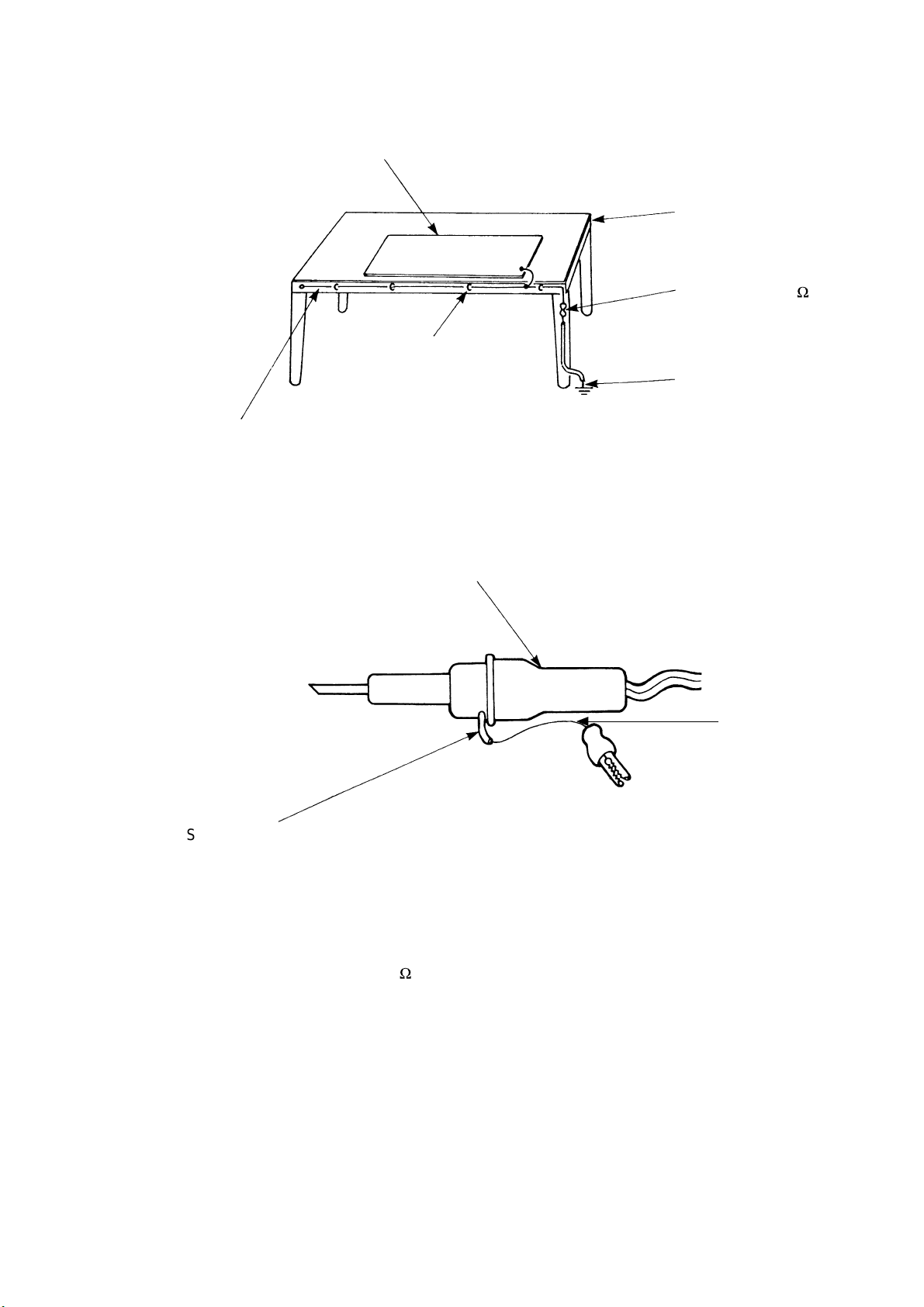
(6) Use a three wire type soldering iron including a grounding wire.
Metal plate (of aluminium, stainless steel, etc.)
Staple
Bare copper wire (for body earth)
Fig. 3. Grounding of the working table
Working
table
Resistor of 1 M (1/2W)
Earth wire
Soldering iron
2
Screw stop at the screwed
part using a rag plate
Fig. 4. Grounding a soldering iron
Use a high insulation mode (100V, 10M or higher) when ordinary iron is to be used.
(7) In checking circuits for maintenance, inspection or some others, be careful not to have the test probes of the
measuring instrument shortcircuit a load circuit or the like.
Grounding
wire
– 3 –
Page 13

CAUTION
!
1. In quiet operation or stopping the running, slight flowing noise of refrigerant in the refrigerating cycle is
heard occasionally, but this noise is not abnormal for the operation.
2. When it thunders near by, it is recommend to stop the operation and to disconnect the power cord plug
from the power outlet for safety.
3. The room air conditioner does not start automatically after recovery of the electric power failure for
preventing fuse blowing. Re-press START/STOP button after 3 minutes from when unit stopped.
4. If the room air conditioner is stopped by adjusting thermostat, or missoperation, and re-start in a moment,
there is occasion that the cooling and heating operation does not start for 3 minutes, it is not abnormal
and this is the result of the operation of IC delay circuit. This IC delay circuit ensures that there is no
danger of blowing fuse or damaging parts even if operation is restarted accidentally.
5. This room air conditioner should not be used at the cooling operation when the outside temperature is
below 10°C (50°F).
6. This room air conditioner (the reverse cycle) should not be used when the outside temperature is below
–10°C (14°F).
If the reverse cycle is used under this condition, the outside heat exchanger is frosted and efficiency falls.
7. When the outside heat exchanger is frosted, the frost is melted by operating the hot gas system, it is not
trouble that at this time fan stops and the vapour may rise from the outside heat exchanger.
– 4 –
Page 14

SPECIFICATIONS
MODEL
RAK-25NH4
RAK-35NH4
RAK-50NH4
RAC-25NH4 RAC-50NH4RAC-35NH4
FAN MOTOR
FAN MOTOR CAPACITOR
FAN MOTOR PROTECTOR
COMPRESSOR
COMPRESSOR MOTOR CAPACITOR
OVERLOAD PROTECTOR
OVERHEAT PROTECTOR
FUSE (for MICROPROCESSOR)
POWER RELAY
POWER SWITCH
TEMPORARY SWITCH
PWM DC35V
NO
NO
–
NO
NO
NO
NO
NO
NO
YES
40 W
NO
NO
JU1012D JU1013D
NO
YES
YES
3.0A
G4A
NO
NO
SERVICE SWITCH
TRANSFORMER
VARISTOR
NOISE SUPPRESSOR
THERMOSTAT
REMOTE CONTROL SWITCH (LIQUID CRYSTAL)
REFRIGERANT CHARGING
VOLUME
(Refrigerant 410A)
UNIT
PIPES (MAX. 20m)
NO
NO
NO
NO
YES(IC)
YES
----------
WITHOUT REFRIGERANT BECAUSE
COUPLING IS FLARE TYPE.
450NR
YES(IC)
1150g1150g
YES
NO
YES
NO
1400g
– 5 –
Page 15
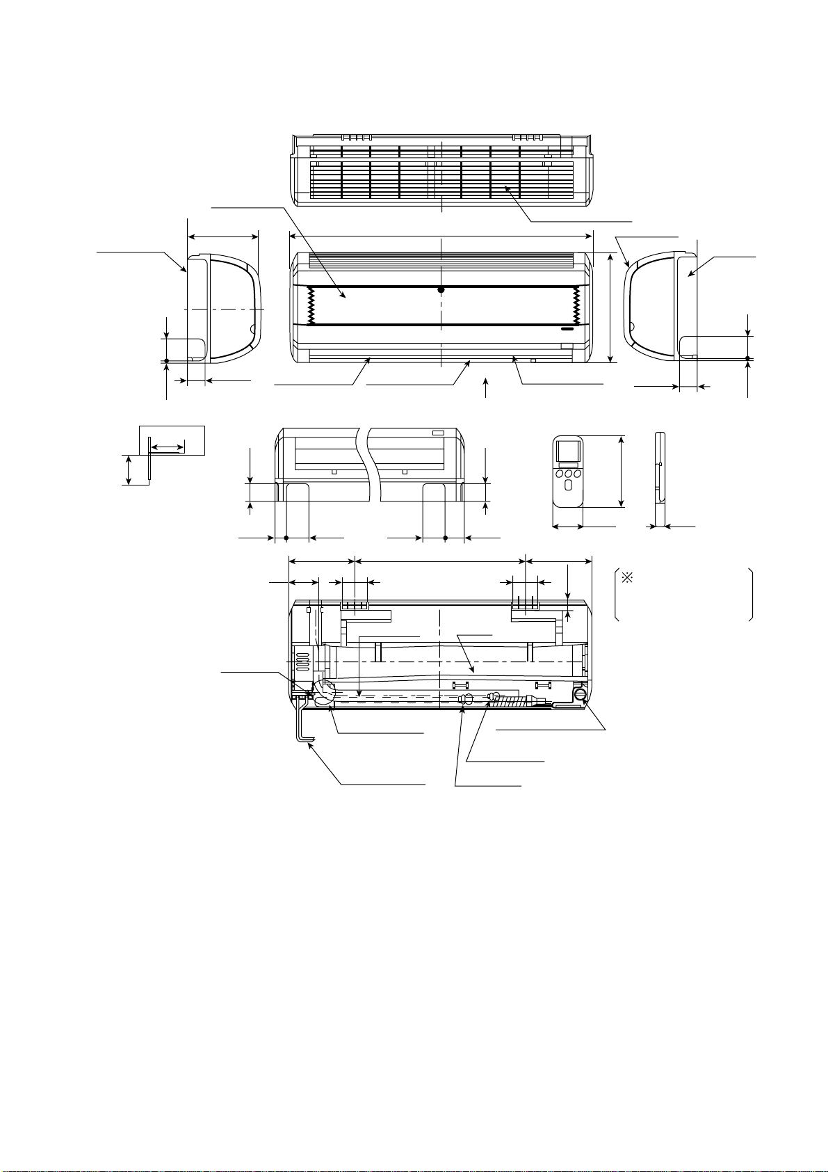
CONSTRUCTION AND DIMENSIONAL DIAGRAM
MODEL RAK-25NH4, RAK-35NH4, RAK-50NH4
Air suction grill
Mounting plate
183
860
Top air suction grill
Front panel
Cabinet
285
About
380
350
About
View from back
(Pipe lead-out)
6.5 60
47
47
31 120.5
Drain outlet
60 60
240 170450
Horizontal deflectorDischarge grill
Drain hose
Hole on the wall
for ø 65mm pipe
P
47
Drain
Narrow pipe
Vertical deflector
7070140
Drain cap
connection port
147
56 17.5
28
47
When piping is
drawn horizontally,
exchange the drain
hose for the drain cap
6.5 60
Connecting cable
– 6 –
Wide pipe
Page 16

CONSTRUCTION AND DIMENSIONAL DIAGRAM FOR OUTDOOR
MODEL RAC-25NH4, RAC-35NH4
852
28 750
16556
76
559
570
195
95
2616 280
166
MODEL RAC-50NH4
10464
Handle
Air suction
grille
955
26 850
Air outlet
79
638
650
340
201
280
2022 298
Handle
96
340
169.5
Fixing hole
Holes for anchor bolt
(2-ø12)
507 198
Notch for anchor bolt
(2-ø12 Notchs)
12
37
57
10
1010
320
340
– 7 –
More than
100
700
More than
100
More than
Service space
More than
100
Page 17

MAIN PARTS COMPONENT
RED
360V
BLK
0V
WHT
15V
M
YEL
0~6V
BLU
0~15V
THERMOSTAT
Thermostat Specifications
MODEL RAK-25NH4, RAK-35NH4, RAK-50NH4
THERMOSTAT MODEL IC
OPERATION MODE COOL HEAT
ON 15.6 (60.1) 20.0 (68.0)
OFF 15.3 (59.5) 20.7 (69.3)
ON 23.6 (74.5) 28.0 (82.4)
OFF 23.3 (73.9) 28.7 83.7)
ON 31.6 (88.9) 36.0 (96.8)
OFF 31.3 (88.3) 36.7 (98.1)
TEMPERATURE
°C (°F)
INDICATION
16
INDICATION
24
INDICATION
32
FAN MOTOR
Fan Motor Specifications
MODEL
RAK-25NH4, RAK-35NH4,
RAK-50NH4
POWER SOURCE DC: 0 ~ 35V
OUTPUT 23W
RED
BLK
WHT
YEL
BLU
CONNECTION
35V
0V
5V
0 ~ 5V
FG
RAC-25NH4, RAC-35NH4,
RAK-50NH4
DC360V
40W
M
(Control circuit built in)
BLU : BLUE YEL : YELLOW BRN : BROWN WHT : WHITE
GRY : GRAY ORN : ORANGE GRN : GREEN RED : RED
BLK : BLACK PNK : PINK VIO : VIOLET
– 8 –
Page 18

COMPRESSOR MOTOR
Compressor Motor Specifications
MODEL
COMPRESSOR MODEL
RAC-25NH4 RAC-50NH4RAC-35NH4
JU1012D JU1013D
PHASE SINGLE
RATED VOLTAGE AC 220 ~ 230 V
RATED FREQUENCY 50 Hz
POLE NUMBER 4
(U)
WHITE
CONNECTION
M
M
M
(W)
(V)
YELLOW
RESISTANCE VALUE
20°C
(68°F)
2M = 1.05
RED
75°C
(167°F)
YELLOW
2M = 1.28
WHITE
RED
!
CAUTION
( )
When the refrigerating cycle has been operated for a long time with the capillary tubes clogged or crushed
or with too little refrigerant, check the color of the refrigerating machine oil inside the compressor. If the
color has been changed conspicuously, replace the compressor.
– 9 –
Page 19

WIRING DIAGRAM
BLU
POWER
RELAY
COIL
NF
COIL 1
C003
C001
C002
VARISTOR1
L001
CT1
VARISTOR3
SURGE
ABSORBER
DIODE
STACK
R010
L002
R011
C011
C010
FAN
MOTOR
VARISTOR2
CN6
WHT
C008
C013
C015
M
WHT YEL
RED
WHT YEL
YEL
YEL
YEL
DIODE
STACK
RED
UVW
REACTOR
SYSTEM POWER
MODULE 2
L2
L1
CN14
CN13
CN11
C503
C502C501
10
CN14
CN10
RED
CN9
BLU
CN8
WHT
CN15
WHT
CN13
CN11
5
5
CN12
CN12
RED
GRY
2A FUSE
ICP RELAY
R008R007
3A FUSE
25A
FUSE
C006
R001
BLK GRN WHT
(WHT) (BRN) (RED)(BLK)
CONNECTING
CORD
BRN RED
BLK
BLK
GRN
RED
BLK
WHT
YEL
BLU
POWER
CIRCUIT
TERMINAL
BOARD
(GRN+YEL)
LNCD
SINGLE PHASE
AC220~230V
50Hz
(GRN+YEL)
THERE ARE SOME LEAD WIRES
WHICH HAVE SPIRAL STRIPES
WITH WHITE IN ADDITION TO
THE ORIGINAL COLOR
CN2
RED
MAIN P.W.B.
REVERSING
VALVE
R002
C007
C012
C014
ELECTRIC EXPANSION
VALVE
OH
THERMISTOR
DEFROST
THERMISTOR
OUTDOOR
TEMPERATURE
THERMISTOR
GRY
GRY
GRY
GRY
RED
RED
COMPRESSOR
MODEL RAK-25NH4 / RAC-25NH4
RAK-35NH4 / RAC-35NH4
RAK-50NH4 / RAC-50NH4
INDOOR UNIT
CONNECTING CORD
FROM OUTDOOR UNIT
(BROWN)
(RED)
GREEN &
YELLOW
INDOOR ROOM
TEMPERATURE
THERMISTOR
HEAT
EXCHANGER
THERMISTOR
TERMINAL
BOARD
C
D
BLACK
BLACK
GRAY
GRAY
BROWN
RED
CN1
CN5 CN9
EEPROM / TEST HA
1234 1 2 3 4
5678
CN12
MAIN P. W. B.
C1 C2 M1 M2
CN4 CN11
4 LINES 5 LINES
CN8
CN10
9 LINES
STEPPING
MOTOR
M
M
INDOOR
FAN MOTOR
WIRELESS
REMOTE CONTROLLER
RECEIVER
P. C. B.
CN3A
CN2A
OUTDOOR UNIT
CN2
LED
P. C. B.
– 10 –
Page 20
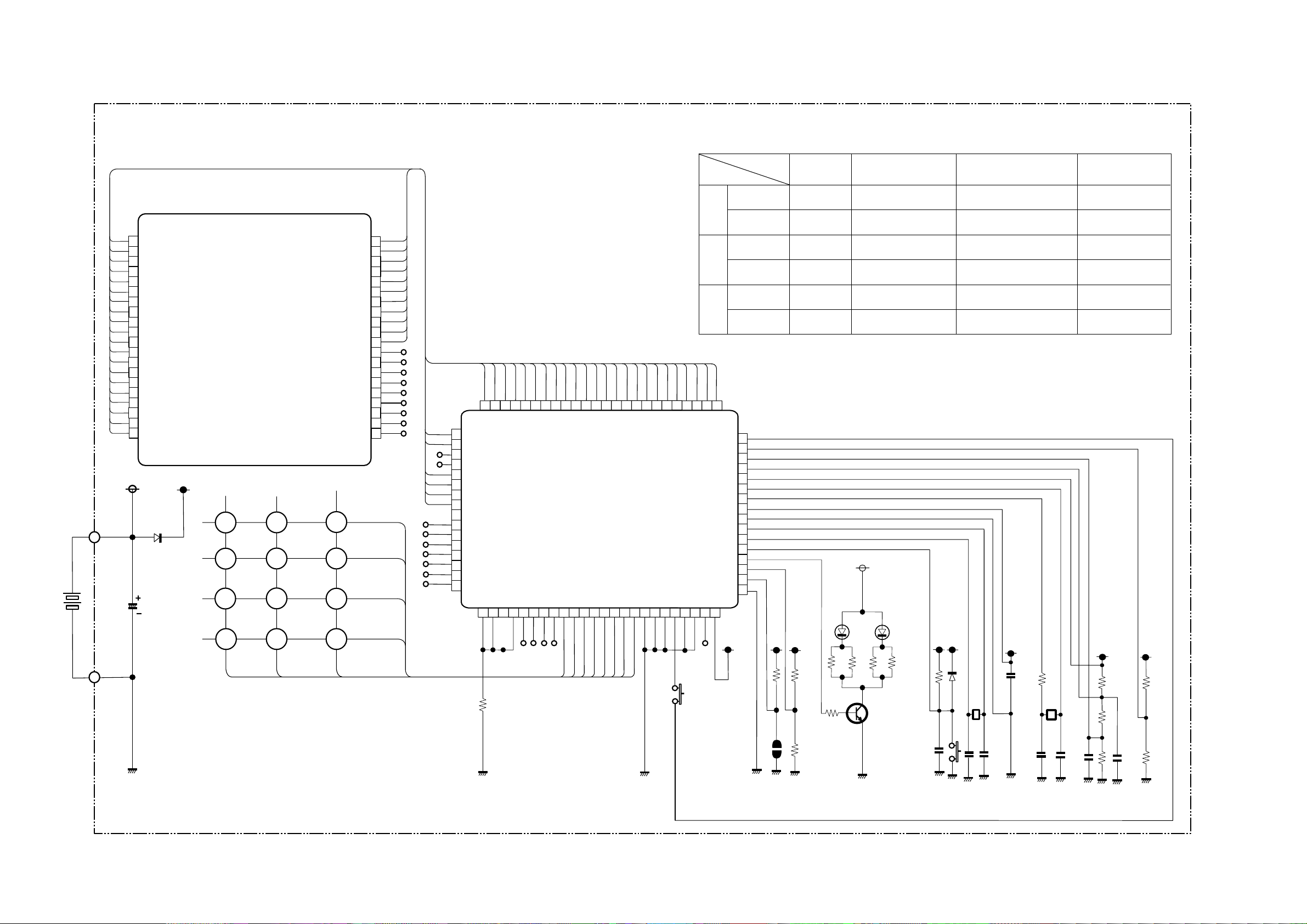
CIRCUIT DIAGRAM
Remote Control
Key matrix table
1
SEG5
2
SEG0
3
SEG1
4
SEG2
5
SEG3
SEG4
6
7
SEG5
8
SEG6
9
SEG7
10
COM3
11
COM2
12
COM1
13
COM0
14
SEG14
15
SEG13
16
SEG12
17
SEG11
18
SEG13
19
SEG9
20
SEG8
D3
RB425D(1/2)
C8
50v/1u
LCD 1
K 1
K2K3
K4
K5
P10
P11
K6
K7 K8
K9 K10
K11K12
SEG20
SEG19
SEG18
SEG17
SEG16
SEG21
SEG27
SEG28
P12
SEG24
SEG25
SEG26
NC
NC
NC
NC
NC
NC
NC
NC
NC
K13 K14
K15 K16
K17
K18
40
39
38
37
36
35
34
33
32
31
30
29
28
27
26
25
24
23
22
21
D0
D1
D2
D3
65
66
67
68
69
70
71
72
73
74
75
76
77
78
79
80
64
SEG20
SEG21
SEG22
SEG23
SEG24
SEG25
SEG26
SEG27
SEG28
SEG29
SEG30
SEG31
SEG32
SEG33
SEG34
SEG35
1
62
63
SEG19
SEG18
P41
P40
3
2
R1
100k
60
61
SEG17
SEG16
P42
P43
5
4
59
58
57
54
SEG14
SEG15
IC 1
56
SEG13
SEG12
55
SEG11
SEG10
SEG9
53
52
51
SEG8
SEG7
50
49
SEG5
SEG6
M3455OM6A-504FP
D2
P00
6
P01
7
P02
8
P03
9
P10
10
P11
11
P12
12
P13
13
D0
14
D1
15
16
48 47
SEG4
D3
17 18
SEG3
D5
D4
45
46
SEG1
SEG2
D6
20
19
Input
P10
P11
P12
43
44
42
SEG0
SEG42
SEG43
NCVL C1
XC OUT
D7
D9
D8
BEEP
22
21
23
SW1
SW-187-2P
Output
D0
Door open Automatic swingFan speed selectionOperation selectionStart/Stop
Door shut ––Automatic swingStart/Stop
Door open Day
Door shut Fan speedRoom temperature downRoom temperature up–
Door open CancelReservation–Off timer
Door shut –––Sleep
41
SEG41
SEG40
40
P30
P31
39
38
37
VL C2
VL C3
36
35
XC IN
34
33
VDD
32
VSS
X OUT
31
X IN
30
29
RESET
28
CARR
27
P23
26
P22
25
24
P21
P20
R2
100k
R3
100k
R5
330
P
R4
100k
R6
D1 D2
EL-1L7
D2D1
R8
R7
R6 R9
24(1/8W)
Q1
2SC3443
or 2SC2982
R9
R10
12M
D3
RB425D
(1/2)
K19
X1
910kHz
C9
105
R11
150k
X2
32.768
kHz
C6
104
• present timeHour downHour upOn timer
D3D2D1
R14
220k
220K
R13
C7
104
R15
100k
R16
100k
C1
334
C2
220p
C3
220p
C4
18p
C5
22p
R12
220k
– 11 –
Page 21

CIRCUIT DIAGRAM
MODEL RAK-25NH4, RAK-35NH4, RAK-50NH4
– 12 –
Page 22

CIRCUIT DIAGRAM
MODEL RAC-25NH4/RAC-35NH4/RAC-50NH4
– 13 –
Page 23

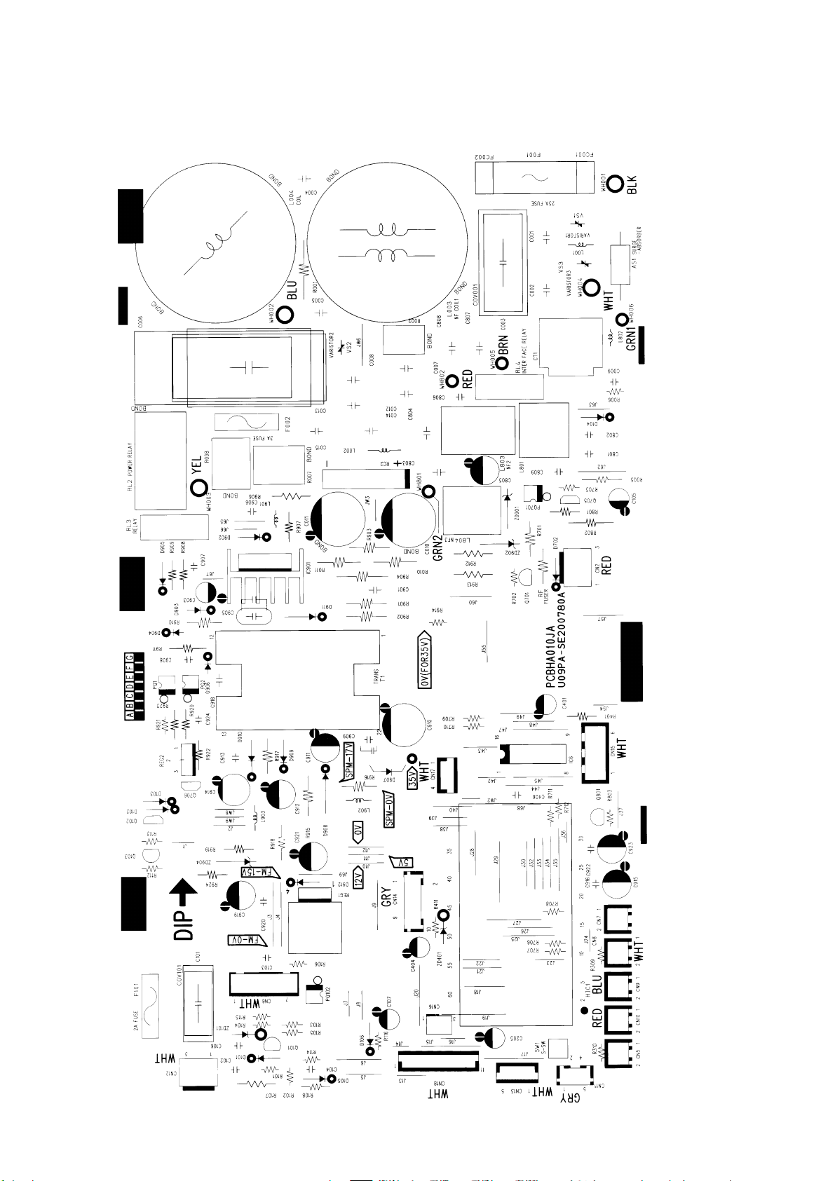
PRINTED WIRING BOARD LOCATION DIAGRAM
MODEL RAK-25NH4, RAK-35NH4, RAK-50NH4
MAIN P.W.B.
Marking on P.W.B.
COMPONENT SIDE
SOLDERING SIDE
1
IVORY
CN5
8
4
1
CN1
WHT
C621
C751
C132
C131 R111
ICP2
1
1
IC402
J29
J30
J17
R631
L751
R751
R114
Q113
R121
ICP1
WHT
CN4
CN8
WHT
J31
J18
J19
J10
5
IVORY
ZD131
Q111
R122
IC111
R112 C112
C111
ZD111
R125
R126
J20
CN6
4
5
BZ
J39
RES1
J33
J32
J34
J11
J12
1
1
HB-098-101A
Q131
C133
R132
Q112
D111
R115
Q115
C103
D821
C823
R825
R823
C822
IVORY
1
CN14
1
J52
J46
J44
J51
J50
J45
J42
J43
J49
J48
J40
J41
J21
J22
J14
J13
J15
CN9
4
BLK
ZD211
R201
R131
ZD121
C123
Q114
C113 R117
R828
R829
R826
R824
R822
1
IC801
4
Q801
R812
J72
Q821
C763
R612
R764
R609
R830
C115
J78
C651
C825
R118
R651
Q803
R119
R761
R120
R658
ID
8
C801
R804
C121
C116
R116
R124
Q116
R123
J79
R827
R821
C803
C804
J801
L801
R806
R805
R803
J16
J23
R811
4
J35
J24
R701
REG2
J37
J36
R606
32
33
R657
R610
C507
R807
R810
C631
R656
R503
J76
R403
J47
R605
R404
Q802
J53
J38
IC501
R500
R654
5
R763
R504
R813
J54
J25
C821
ICP3C762
R219
R653
WHT
CN11
J55
R743
R604
R603
17
C601
R505
1
C114
C122
J26
J27
C802
J83
Q722
R745
R742
R744R741
R611
C506
16
R501
R602
C824
R641
R601
J75
R652
J71
AUTO RESTART
CANCEL
L111
R506
R508
L501
R502
C501
C611
R514
R507
R655
IC711
C524
R746
C521
R509
J82
1
R515
R510
HB–098–101A
J56
L101
C101
D101
13
L743 L742 L741
16
J81
1
C522
IC521
R521
R522
C505
C304
R307
C302
R511
R512
R513
J74
R308
C104
R127
C502
Q521
D402
R650
C102
CN12
WHT
C711
R305
C523
C401
R128
F
No.
Lot
J28
J80
R301
1
CN10
IVORY
6
9
R749
8
R748
R747
IC401
R401
R402
J77
D403
D401
R306
C303
R303
J73
R302
J70
RECEIVING P.W.B.
Marking on P.W.B.
Lot No.
IR1
1 14
J57
C1
IVORY
CN2A
IVORY
CN3A
COMPONENT SIDE
F
SW1
9
HB-098-102A
– 14 –
R1
R2
SOLDERING SIDE
Page 24
MODEL RAC-25NH4, RAC-35NH4, RAC-50NH4
MAIN P.W.B. Marking on P.W.B
COMPONENT SIDE
– 15 –
Page 25

RAK-25NH4 / RAC-25NH4
RAK-35NH4 / RAC-35NH4
RAK-50NH4 / RAC-50NH4
LCD wireless
Room temperature
thermistor
Wireless receive
circuit
Filter.
Operation.
Timer.
Power source
1ø, 50Hz, 220~230V
L
N
Outdoor
unit
Terminal
board
SPM2
Trip signal
synthesis circuit
Heat exchanger
thermistor
Temporary switch
Initial setting circuit
Reset circuit
Auto sweep motor for
Air deflector
Indoor microcomputer (AX-7R11)
Outdoor microcomputer / HIC (AX-8N00)
Electric Expansion valve
drive circuit
Electric
Expansion
valve
– 16 –
Page 26
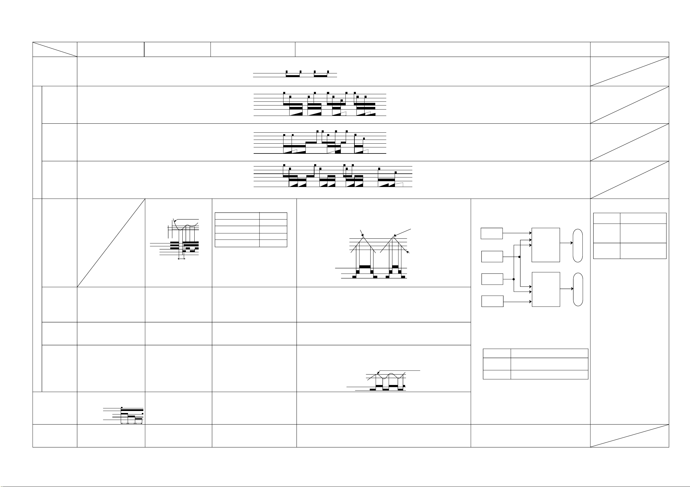
BASIC MODE
MODEL RAK-25NH4, RAK-35NH4, RAK-50NH4
Operation mode
Basic operation of
start/stop switch
Off-timer
On-timer
Timer functions
Off -> On
On -> Off timer
Auto
Hi
Med
Fan speed mode (indoor fan)
Lo
Basic operation of
temperature controller
Sleep operation
(with sleep button ON)
Operates at “Hi” regardless of the
room temperature.
Operates at “Med” regardless of
the room temperature.
Operates at “Lo” regardless of the
room temperature.
Performs only fan operation at the
set speed regardless of the room
temperature.
• Enters sleep operation after set
as on the left.
• Action during sleep operation
Lo (sleep) operation
Fan
Start/stop switch
Operation lamp
Hi
Med
Fan
Speed
Lo
Hi Med Lo
Changes from “Hi” to “Med” or
“Lo” depending on room
temperature.
Temperature set
for cooling
Thermo iudgment
Compressor
Hi
Med
Lo
1. Runs at “Hi” until first thermo
off after operation is started.
2. Runs at “Lo” when thermo is
off.
Set to “ultra-Hi” when the
compressor runs at maximum
speed, and to “Hi” in other modes.
Same as at left.
Same as at left.
See page 49.
• Same as at left
• See page 51.
(Compressor stopped
forcibly for 3 minutes)
Dehumidifying
(dehumidifying operation by the
function select button only, not including
that engaged by the dehumidify button)
Start/stop switch
Operation tamp
Start/stop switch
Operation tamp
Cancel switch
Operation temp
Timer tamp
Timer memory
Srart/stop switch
Reserve switch
Cancel switch
Operation temp
Timer tamp
Timer memory
Start/stop switch
Reserve switch
Cancel switch
Operation lamp
Timer lamp
Timer memory
Start
(Change in reserved time)
Changes between “Lo” and “Med”
depending on the room temperature.
Fan speedTemperature division
Division 1
Division 2
Division 3
Division 4
Lo
Lo
Med
Med
1. The indoor fan also stops when the
compressor is in stop status.
Set to “Hi” in modes other than when the
compressor stops.
Set to “Med” in modes other than when the
compressor stops.
Set to “Lo” in modes other than when the
compressor stops.
See page 53.
• Same as at left
• See page 53.
Stop
Start Stop
(Off-timer during stop)
(On-timer during operation)
ON ONONOFF OFF OFF ONOFF
(Off->On timer) (On->Off timer) (On->Off timer)
(Change in reserved time)
during operation)
(Off->On timer)
during stop)
Set to “ultra-Lo”, “Lo”, “Med”, “Hi”, “ultra-Hi” or “stop” depending on the room temperature,
time and heat exchange temperature. Set to “stop” if the room temperature is 18˚C in the
“ultra-Lo” mode other than during preheating (cooling is recovered at 18.33˚C).
When the compressor is running at maximum speed
during hot dash or when recovered from defrosting.
˚C
42. 66
37. 66
32. 66
29. 66
Hi or ultra-HI
(fan speed set
to “auto”)
Med
Lo
In modes other than
left
Heat exchanger
temperature
Set to “ultra-Lo”, “Lo”, “Med”, “Hi”, “ultra-Hi” or “stop” depending on the room temperature, and
time. Set to “stop” if the room temperature is 18˚C in the “ultra-Lo” mode other than during
preheating (cooling is recovered at 18.33˚C).
Set to “ultra-Hi” when the compressor is running at maximum speed during hot dash or when
recovered from defrosting.
Set to “ultra-Lo”, “Lo”, “Med” or “stop” depending on the room temperature and time. Set to
“stop” if the room temperature is 18˚C in the “ultra-Lo” mode other than during preseating
(cooling is recovered at 18.33˚C).
Set to “ultra-Lo”, “Lo”, or “stop” depending on the room temperature and time. Set to “stop” if
the room temperature is 18˚C in the “ultra-Lo” mode other than during preseating (cooling is
recovered at 18.33˚C). The fan speed is controlled by the heat exchanger temperature; the
overload control is executed as in the following diagram:
KAFON
KAFOF
“Med” with overload
“Lo”
Heat exchanger temperature
See page 55.
• Same as at left
• See page 57.
N&F autoHeatingCooling
The neuro & fuzzy control allows device to determine optimum
operation mode and set temperature. However, during auto
cooling, the new cool rhythm starts when the room temperature
is less than the set temperature plus 0.66˚C, after dash is
finished.
Room
temperature
Outdoor
temperature
Calendar
Humidity
Neuro
pattern
recognition
Fuzzy
control
Operation mode
Set temperature
Notes:
(1) The set temperature can be varied ±3˚C using the
temperature setting buttons and .
v
v
(2) If operation is started by tele-control or by temporary switch
in status where remote control has not been used after
power was supplied, the operation mode will be as follows
(since there is no stored calendar data):
Room temparature at
operation start (˚C)
Cooling
Dehumidifying
Heating
Set temperature: 28˚C
Fan mode: Auto
Set temperature: Room temperature at operation
Fan mode: Auto
Set temperature: 22˚C
Fan mode: Auto
start
• Same as at left.
• Performs the sleep operation of each operation mode.
Special auto (not normally used)
The special auto mode is based on N&F
auto, but the following is different:
Operation mode
N&F auto
Special auto
Mode change during
operation
Does not change as long as
outdoor temperature or
calendar data does not
change greatly.
The operation mode will be
judged the same as at
operation start every hour.
The special auto operation mode is
entered when operation is started in the
following status:
<Start condition>
Power is supplied white the tele-control
signal is being input. (Operation starts
automatically.)
<End condition>
The remote control restores the normal
operation mode.
Note
(1) Since there is no stored calendar
data, N&F control is not determined.
See Note (2) of N&F auto.
– 17 –
Page 27

Table 1 Mode data file
RAK-25NH4 RAK-35NH4 RAK-50NH4
LABEL NAME VALUE
WMAX 4500 min
WMAX2 4600 min
WSTD 3250 min
WBEMAX 2600 min
CMAX 2900 min
CMAX2 3000 min
CSTD 2500 min
CKYMAX 2200 min
CJKMAX 2000 min
CBEMAX 1800 min
WMIN 1200 min
CMIN 1500 min
–1
–1
–1
–1
–1
–1
–1
–1
–1
–1
–1
–1
5500 min
5600 min
4350 min
2800 min
3700 min
3800 min
3550 min
2800 min
2500 min
2200 min
1200 min
1500 min
–1
–1
–1
–1
–1
–1
–1
–1
–1
–1
–1
–1
6200 min
6250 min
5200 min
2600 min
5700 min
5800 min
5200 min
3550 min
2700 min
2000 min
1200 min
1500 min
–1
–1
–1
–1
–1
–1
–1
–1
–1
–1
–1
–1
STARTMC 60 Seconds 60 Seconds 60 Seconds
DWNRATEW 80% 80% 80%
DWNRATEC 80% 80% 80%
SHIFTW 3.33°C 3.33°C 3.33°C
SHIFTC 1.00°C 1.00°C 0.33°C
CLMXTP 30.00°C 30.00°C 30.00°C
YNEOF 22.00°C 22.00°C 28.00°C
TEION 5.00°C 5.00°C 2.00°C
TEIOF 9.00°C 9.00°C 9.00°C
SFTDSW 1.00°C 1.00°C 1.00°C
DFTIM1 45 Minutes 45 Minutes 45 Minutes
DFTIM2 60 Minutes 60 Minutes 60 Minutes
– 18 –
Page 28

NOTE (9)
Reversing valve (heating “on” mode)
Notes:
(1) Condition for entering into Cool Dashed mode. When fan set to “Hi” or “Auto mode” and temperature difference between indoor temperature and set temperature has a
corresponding compressor rpm (calculated value in Table 7) larger than WMAX.
(2) Cool Dashed will release when i) a maximum 25 minutes is lapsed and ii) room temperature is lower than set temperature –3°C (thermo off) and iii) when room temperature
has achieved setting temperature –1°C then maximum Cool Dashed time will be revised to 20 minutes. And iv) indoor fan is set to Lo and Med fan mode and v) change operation
mode.
(3) During Cool Dashed operation, thermo off temperature is set temperature (with shift value) –3°C. After thermo off, operation continue in Fuzzy control mode.
(4) Compressor minimum “ON” time and “OFF” time is 3 minutes.
(5) During normal cooling mode, compressor maximum rpm CMAX will maintain for 60 minutes if indoor temperature is lower than CLMXTP. No time constrain if indoor temperature
is higher than CLMXTP.
(6) When fan is set to “Hi”, compressor rpm will be limited to CKYMAX.
(7) When fan is set to “Med”, compressor rpm will be limited to CJKMAX.
(8) When fan is set to “Lo”, compressor rpm will be limited to CBEMAX.
(9) During Cool Dashed, when room temperature reaches set temperature –1°C compressor rpm is actual rpm x DWNRATEC.
Table 2 ∆TCMAX
Temperature Calculated
difference compressor rpm
1.66 2265 min
2 2435 min
2.33 2600 min
2.66 2765 min
3 2935 min
3.33 3100 min
3.66 3265 min
4 3435 min
4.33 3600 min
4.66 3765 min
5 3935 min
5.33 4100 min
5.66 4265 min
6 4435 min
6.33 4600 min
6.66 4765 min
7 4935 min
7.33 5100 min
7.66 5265 min
8 5435 min
8.33 5600 min
8.66 5765 min
9 5935 min
9.33 6100 min
9.66 6265 min
10 6435 min
10.33 6600 min
10.66 6765 min
11 6935 min
–1
–1
–1
–1
–1
–1
–1
–1
–1
–1
–1
–1
–1
–1
–1
–1
–1
–1
–1
–1
–1
–1
–1
–1
–1
–1
–1
–1
–1
Note:
1. See the data in Table 1 on
page 47 for each constant in
capital letters in the diagrams.
– 19 –
Page 29
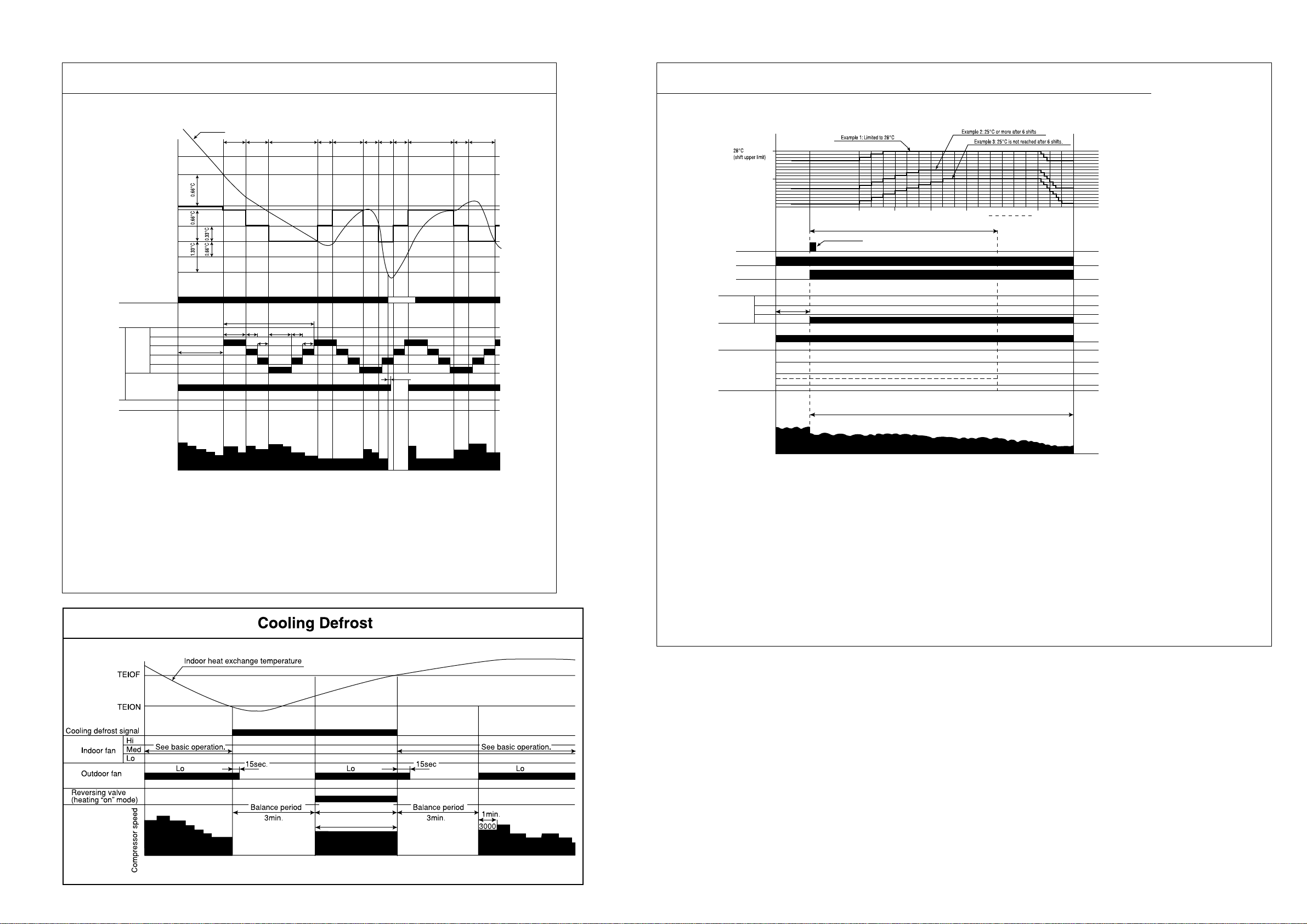
New Cool Rhythm
Cooling Sleep Operation
Final set temperature
(Cooling/dehumidifying set
temperature
(temperature set by remote
control (+) SHIFTC)
Set temperature during rhythm
(temperature set by remote
control (+) SFTRZM)
Thermo judgment
Hi
Indoor
fan
New cool rhythm
Outdoor fan
Lo
Rhythm Med
Rhythm Lo
Med
Room temperature
See basic operation.
Lo
Minimum
5min.
5 sec. 5 sec.
Minimum 5min. Minimum 5min.
5min.
1 cycle
2.5 sec. 2.5 sec.
4.5 sec.
2.5 sec.
5min.
Minimum
5min.
5min.
Minimum
5min.
Thermo OFF
15 sec.
Minimum
5min.5min.
5min.
Lo
Final set temperature
(Cooling/dehumidifying set
temperature (+) sleep shift)
(Cooling/dehumidifying set
temperature = Remote control set
temperature (+) SHIFTC)
Sleep key
Operation lamp
Timer lamp
Indoor fan
Outdoor fan
Horizontal air
deflector
Hi
Med
Lo (sleep)
Shut
Horizontal
Facing down
See basic operation
Lo
Set to 7 hours
0.5hr
1.5hr
2.5hr 3.5hr 6hr 7hr
3hr
Maximum speed
P1
Compressor speed
Notes:
(1) New cool rhythm is engaged when the fan speed is “auto” and the room temperature is less than
set one plus 0.66˚C in the “auto” operation mode or cooling mode.
(2) The minimum new cool rhythm time is 10 minutes when the temperature falls and rises.
(3) Cool rhythm is not engaged during Nice temperature, Sleep operation.
(4) Pl control is engaged during new cool rhythm: the speed limit is the same as during normal operation.
(5) The new cool rhythm set temperature is also shifted during thermo OFF.
Compressor speed
Notes:
(1) The sleep operation starts when the sleep key is pressed.
(2) When the sleep key is set, the maximum compressor speed is limited, and the indoor fan is set to “sleep Lo”.
(3) 30 minutes after the sleep key is set, the sleep shift of temperature starts, and upper shift is made at least 6 times. If 25˚C
is not reached after 6 shifts, shifts repeat unit 25˚C is reached.
(4) The sleep shift upper value of set temperature is 28˚C.
(5) After 6 hours, a shift down to the initial set temperature is made at a rate of 0.33˚C/5 min.
(6) If the operation mode is changed during sleep operation, the set temperature is cleared, and shift starts from the point when
switching is made.
(7) The indoor fan speed does not change even when the fan speed mode is changed.
(8) When operation is stopped during sleep operation, the set temperature when stopped, as well as the time, continue to be
counted.
(9) If the set lime is changed during sleep operation, all data including set temperature, time, etc. is cleared and restarted.
(10) If sleep operation is canceled by the cancel key or sleep key, all data is cleared.
Reverse cycle period
MAX. 12min.
min–1
3000
fixed
– 20 –
Page 30

+
+
–1.33˚C
–0.66˚C
Delay
Notes:
(1) If the room temperature is (cooling preset temperature) - (1.33 °C) or less after 30 seconds from starting the operation, the operation is done assuming
as the preset temperature = (room temperature at the time) - (2°C).
(2) The indoor fan is operated in the “Lo” mode. During thermo OFF indoor fan will be OFF for 5 minutes and ON for 1 minute.
(3) When the operation is started by the themostat turning ON, the start of the indoor fan is delayed 32 seconds after the start of compressor operation.
(4) The compressor is operated forcedly for 3 minutes after operation is started.
(5) The minimum ON time and OFF time of the compressor are 3 minutes.
– 21 –
Page 31

Basic Heating Operation
SFTDSW
Heating set temperature
(remote control set temperature
(+))
Dash period
TWMAX
Fan speed set to "auto"
Ultra-Hi
Hi
Med
10sec.
Lo
Ultra-Lo
Wtd
WMIN
0
Start
Max. 3 min.
Preheating released
30sec. 30sec.
1 min.
WMAX2
ultra Hi
Control by
heat exchanger temperature
NOTE (11)
Lo Hi Hi Hi
Start/stop switch
Thermo judgment
Defrost signal
Preheating judgment
Indoor fan
Operation lamp
Max.
(WMAX)
Rating
(WSTD)
Compressor speed
3000
Reversing valve (heating "on" model)
Outdoor fan
Notes:
(1) Condition for entering into Hot Dashed mode. When fan set to “Hi” or “Auto mode” and i) Indoor temperature is lower than 18°C, and ii) outdoor temperature is lower than 10°C,
and iii) Temperature difference between indoor temperature and set temperature has a corresponding compressor rpm (calculated value in Table 3) larger than WMAX.
(2) Hot Dashed will release when i) Room temperature has achieved the set temperature + SFTDSW. ii) Thermo off.
(3) During Hot Dashed operation, thermo off temperature is set temperature (with shift value) +3°C. After thermo off, operation continue in Fuzzy control mode.
(4) Compressor minimum “ON” time and “OFF” time is 3 minutes.
(5) During normal heating mode, compressor maximum rpm WMAX will maintain for 120 minutes if indoor temperature is higher than 18°C. No time limit constrain if indoor temperature
is lower than 18°C and outdoor temperature is lower than 2°C.
(6) During Hotkeep or Defrost mode, indoor operation lamp will blink at interval of 3 seconds “ON” and 0.5 second “OFF”.
(7) When heating mode starts, it will enter into Hotkeep mode if indoor heat exchanger temperature is lower than YNEOF + 0.33°C.
(8) When fan is set to “Med” or “Lo”, compressor rpm will be limited to WBEMAX.
(9) In “Ultra-Lo” fan mode, if indoor temperature is lower than 18°C, indoor fan will stop. If indoor temperature is higher than 18°C + 0.33°C, fan will continue in “Ultra-Lo” mode.
During Hotkeep or Defrost mode, fan will continue in “Ultra-Lo” mode.
(10) During Hot Dashed or outdoor temperature is lower than –5°C, compressor rpm is WMAX2.
(11) During Hot Dashed, when room temperature reaches set temperature + SFTDSW compressor rpm is actual rpm x DWNRATEW.
1.33˚C.
0.66˚C.
Stop Start Start StopStop
Thermo
OFF
30sec. 30sec.
10sec.
15sec. 15sec. 15sec.
10sec.
15sec. 15sec.
Control by
heat exchanger temperature
Control by
heat exchanger temperature
18˚C
Thermo OFF
Thermo
Preheat released
30sec. 30sec.30sec. 30sec. 30sec. 30sec.
10sec.
Control by
10sec.
150sec. Delay150sec. Delay
heat exchanger temperature
15sec.
15sec.
Control by
heat exchanger temperature
3min.
Hi
OFF
15sec.
150sec. Delay
Table 3 ∆TWMAX
Temperature Calculated
difference compressor rpm
1.66 1965 min
2 2135 min
2.33 2300 min
2.66 2465 min
3 2635 min
3.33 2800 min
3.66 2965 min
4 3135 min
4.33 3300 min
4.66 3465 min
5 3635 min
5.33 3800 min
5.66 3965 min
6 4135 min
6.33 4300 min
6.66 4465 min
7 4635 min
7.33 4800 min
7.66 4965 min
8 5135 min
8.33 5300 min
8.66 5465 min
9 5635 min
9.33 5800 min
9.66 5965 min
10 6135 min
10.33 6300 min
10.66 6465 min
11 6635 min
–1
–1
–1
–1
–1
–1
–1
–1
–1
–1
–1
–1
–1
–1
–1
–1
–1
–1
–1
–1
–1
–1
–1
–1
–1
–1
–1
–1
–1
Notes:
1. See the data in Table 1 on
page 47 for each constant in
capital letters in the diagrams.
– 22 –
Page 32

WMIN
1 min
Notes:
(1) The sleep operation starts when the sleep key is pressed.
(2) When the sleep key is set, the maximum compressor speed is limited to WSTD+2000/2, and the indoor fan is set
to “sleep Lo”.
(3) 30 minutes after the sleep key is set, the sleep shift of set temperature starts.
(4) The maximum sleep shift of set temperature is 5°C, and the minimum is 12°C.
(5) If the operation mode is changed during sleep operation, the changed operation mode is set and sleep control
starts.
(6) The indoor fan speed does not change even when the fan speed mode is changed. (Lo)
(7) When defrosting is to be set during sleep operation, defrosting is engaged and sleep operation is restored after
defrosting.
(8) When operation is stopped during sleep operation, the set temperature when stopped, as well as the time, continue
to be counted.
(9) If the set time is changed during sleep operation, all data including set temperature, time, etc. is cleared and
restarted.
(10) If sleep operation is canceled by the cancel key or sleep key, all data is cleared.
– 23 –
Page 33

REFRIGERATING CYCLE DIAGRAM
MODEL RAK-25NH4 / RAC-25NH4
RAK-35NH4 / RAC-35NH4
COOLING, DEHUMIDIFYING, DEFROSTING
OUTDOOR UNIT
STRAINER
CHARGING PIPE
ELECTRIC
EXP ANSION VAL VE
STRAINER
COMPRESSOR
REVERSING
VALVE
SERVICE V ALVE
SUCTION
TANK
(1/4)
SERVICE V ALVE
(3/8)
INDOOR UNIT
SINGLE-ENDED
UNION (3/8)
SINGLE-ENDED
UNION (1/4)
HEATING
OUTDOOR UNIT
STRAINER
CHARGING PIPE
ELECTRIC
EXP ANSION VAL VE
STRAINER
COMPRESSOR
REVERSING
VALVE
SERVICE V ALVE
SUCTION
TANK
(1/4)
SERVICE V ALVE
(3/8)
INDOOR UNIT
SINGLE-ENDED
UNION (3/8)
SINGLE-ENDED
UNION (1/4)
– 24 –
Page 34

REFRIGERATING CYCLE DIAGRAM
MODEL RAK-50NH4 / RAC-50NH4
COOLING, DEHUMIDIFYING, DEFROSTING
OUTDOOR UNIT
ELECTRIC
EXP ANSION VAL VE
STRAINER
STRAINER
COMPRESSOR
REVERSING
VALVE
SERVICE V ALVE
SERVICE V ALVE
(1/2)
SUCTION
TANK
(1/4)
INDOOR UNIT
SINGLE-ENDED
UNION (1/2)
SINGLE-ENDED
UNION (1/4)
HEATING
OUTDOOR UNIT
ELECTRIC
EXP ANSION VAL VE
STRAINER
STRAINER
COMPRESSOR
REVERSING
VALVE
SERVICE V ALVE
SERVICE V ALVE
SUCTION
TANK
(1/4)
(1/2)
INDOOR UNIT
SINGLE-ENDED
UNION (1/2)
SINGLE-ENDED
UNION (1/4)
– 25 –
Page 35

AUTO SWING FUNCTION
MODEL: RAK-25NH4, RAK-35NH4, RAK-50NH4
PRESENT CONDITION
INPUT SIGNAL
OPERATION OPERATION MODE AIR DEFLECTOR
OPERATING SPECIFICATION
REFERENCE
ONE SWING (CLOSING AIR DEFLECTOR)
KEY INPUT
STOP
DURING
OPERATION
– 26 –
THERMO. ON
(INTERNAL FAN
ON)
THERMO. ON
(INTERNAL FAN
OFF)
DURING
OPERATION
EACH MODE
AUTO COOL
COOL
FAN
AUTO DRY
DRY
AUTO HEAT
HEAT
CIRCULATOR
AUTO DRY
DRY
AUTO HAET
HEAT
CIRCULATOR
STOP
DURING ONE SWING
STOP
DURING SWINGING
STOP
DURING SWINGING
TEMPORARY STOP
DURING SWINGING
1 DOWNWARD
2 UPWARD
STOP AT THE MOMENT.
START SWINGING
1 DOWNWARD
2 UPWARD
3 DOWNWARD
STOP AT THE MOMENT.
START SWINGING
1 DOWNWARD
2 UPWARD
3 DOWNWARD
STOP AT THE MOMENT.
START SWING AGAIN.
STOP SWINGING TEMPORARILY.
(SWING MODE IS CLEARED IF SWING COMMAND IS
TRANSMITTED DURING TEMPORARY STOP.)
INITIALIZE AT NEXT
OPERATION.
MAIN SWITCH
ON
MAIN SWITCH
OFF
CHANGE OF
OPERATION
STOP
DURING
OPERATION
DURING
OPERATION
COOL
FAN
DRY
HEAT
CIRCULATOR
EACH MODE
EACH MODE
STOP
DURING ONE SWING
STOP
DURING ONE SWING
STOP
DURING SWINGING
DURING
INITIALIZING
STOP
DURING SWINGING
INITIALIZE
1 DOWNWARD
2 UPWARD
INITIALIZE
1 DOWNWARD
ONE SWING (CLOSING AIR DEFLECTOR)
1 DOWNWARD
2 UPWARD
INITIALIZING CONDITION OF EACH MODE.
STOP SWINGING AND MODE BECOMES INITIALIZING
CONDITION.
INITIALIZE AT NEXT
OPERATION.
Page 36

DESCRIPTION OF MAIN CIRCUIT OPERATION
MODEL RAK-25NH4, RAK-35NH4, RAK-50NH4
1. Reset Circuit
5V
2
R522
1
C521
R521
5
C524
NORMAL : HI
RESET : LO
RES
7
Microcomputer
C522
Voltage
Voltage supply to
2
pin
of IC521
Reset release at 4.4V
3
IC521
0V
Fig. 1-1
5.0V
Reset enter at 4.2V
voltage
Voltage at pin
of microcomputer
7
5.0V
Fig. 1-2
● The reset circuit initializes the microcomputer program when power is ON or OFF.
● Low voltage at pin 7 resets the microcomputer and Hi activates the microcomputer.
● When power “ON” 5V voltage rises and reaches 4.4V, pin 1 of IC521 is set to “Hi”. At this time the
microcomputer starts operation.
● When power “OFF” voltage drops and reaches 4.2V, pin 1 of IC521 is set to “Low”. This will RESET the
microcomputer.
– 27 –
Page 37

2. Receiver Circuit
12V
C1
▲
ZD211
0V
R1
IR1
VDD
GND
R2 R611
V
out
C611
0V
13 RECEIVER I/P
Microcomputer
R201
Fig. 2-1
● The light receiver unit receives the infrared signal from the wireless remote control. The receiver amplifies
and shapes the signal and outputs it.
3. Buzzer Circuit
12V
Microcomputer
Buzzer output
● When the buzzer sounds, an approx.
3.9kHz square signal is output from buzzer
output pin of the microcomputer. After
30
the amplitude of this signal has been set
to 12Vp-p by a transistor, it is applied to
the buzzer. The piezoelectric element in
the buzzer oscillates to generate the
buzzer’s sound.
R219
30
Fig. 3-1 Buzzer Circuit
Metal diaphragm
BZ
0V
BZ1
Q722
Pizoelectric element
Sound wave
– 28 –
V
Fig. 3-2 Buzzer Operation
V
Page 38

4. Auto Sweep Motor Circuit
12V
IC711
Auto sweep motor for
horizontal air defectors
9
Microcomputer
18
17
16
15
C711
7
6
5
4
10
11
12
13
Rotor
8
0V
Fig.4-1
● Fig. 4-1 shows the Auto sweep motor drive circuit; the signals shown in Fig.4-2 are output from pins
15 – 18 of microcomputer.
Microcomputer pins Step width
Horizontal air deflectors
15
16
17
18
12345678
Horizontal air
deflectors: 10ms.
Fig.4-2 Microcomputer Output Signals
● As the microcomputer’s outputs change as shown in Fig.4-2, the core of the auto sweep motor is excited
to turn the rotor. Table 4-1 shows the rotation angle of horizontal air deflectors.
Table 4-1 Auto sweep Motor Rotation
Rotation angle per step (˚ ) Time per step (ms.)
0.0882 10Horizontal air deflectors
– 29 –
Page 39

5. Room Temperature Thermistor Circuit
5
4
3
2
1
0
010
Room temperature (˚C)
Fig. 5-2
20 30 40
0V
Room
temperature
thermistor
0V
5V
Fig. 5-1
62
A
R305
C302
Microcomputer
Room
temp. input
Voltage at
(V)
R301
0V
Heat exchanger
temperature thermistor
0V
5V
Fig. 6-1
61
A
R306
C303
Microcomputer
Heat
exchanger
temperature
input
R302
A
5
4
3
2
1
0
010
-10
Heat exchanger temperature (˚C)
Fig. 6-2
20 30 40
Voltage at
(V)A
● Fig. 5-1 shows the room temperature
thermistor circuit.
6. Heat exchanger temperature thermistor circuit
● The voltage at depends on the room
A
temperature as shown in Fig. 5-2.
● The circuit detects the indoor heat
exchanger temperature and controls
the following.
(1) Preheating.
(2) Low-temperature defrosting
during cooling and dehumidifying
operation.
(3) Detection of the reversing valve
non-operation or heat exchanger
temperature thermistor open.
The voltage at depends on the
A
heat exchanger temperature as shown
in Fig. 6-2.
– 30 –
Page 40

7. Initial Setting Circuit (IC401)
● When power is supplied, the microcomputer reads the data in IC401 or IC402 (E
2
PROM) and sets the
preheating activation value and the rating and maximum speed of the compressor, etc. to their initial
values.
● Data of self-diagnosis mode is stored in IC401 or IC402; data will not be erased even when power is
turned off.
5V
5V 5V
1
2
3
4
IC401 or IC402 (E
0V
8
7
6
5
2
0V
PROM)
C401
0V
R404
R403
27
26
SCL
SDA
Microcomputer
External ROM
}
Fig. 7-1
– 31 –
Page 41

Model RAC-25NH4, RAC-35NH4, RAC-50NH4
1. Power Circuit
TERMINAL
BOARD
L
N
25A FUSE
SURGEABSORBER
VARISTOR3
L001
NF COIL1
C001
VARISTOR1
C003
C002
CT1
C009
0V
0V
COIL
C004C005
R001
C006
POWER RELAY
R007
R008
ICP RELAY
DIODE
STACK 1
(D25VB60)
SPM2
TB8
TB2
REACTOR
L1 L2
TB7 TB6
TB10
U
Vdba
N1
P1
TB11
TB12
V
W
3A FUSE
VARISTOR2
STACK 2 (RC2)
C010
C011
POWER CIRCUIT
R010R011
DIODE
L002
C014
C015
C012
C013
C007
C008
JW6
R002
Fig. 1-1
● This circuit full-wave rectifies 220-230V AC applied between terminals L and N, and boosts it to a required
voltage with the active module, to create a DC voltage.
The voltage becomes 260-360V when the compressor is operated
(1) Active module
The active filter, consisting of a reactor and
switching element, eliminates higher
harmonic components contained in the
current generated when the compressor is
operated, and improves the power-factor.
< Reference >
● In case of malfunction or defective connection:
Immediately after the compressor starts, it may stop
due to “abnormally low speed” active error, etc.
The compressor may continue to operate normally,
but the power-factor will decrease, the operation
current will increase, and the overcurrent breaker
(2) Diode stacks
These rectify the 220-230V AC from
terminals L and N to a DC power supply.
of the household power board will probably activate.
● In case of active module faulty or defective
connection:
Although the compressor continues to operate
normally, the power-factor will decrease, the
operation current will increase, and the overcurrent
breaker of the household power board will probably
activate.
< Reference >
● If diode stack 1 is faulty, the compressor may stop
due to “lp”, “anbormally low speed”, etc. immediately
after it starts, or it may not operate at all because
no DC voltage is generated between the positive e
and negative d terminals.
If diode stack 1 is faulty, be aware that the 25A
fuse might also have blown.
● If diode stack 2 is faulty, DC voltage may not be
generated and the compressor may not operate at
all. Also, be aware that the 3A fuse might have
blown.
– 32 –
Page 42

(3) Smoothing capacitor (C501, C502, C503)
This smoothes (averages) the voltage rectified by the diode stacks.
<Notes > Smoothing capacitor C501 is not available for model RAC-25NH4 and RAC-35NH4.
Smoothing Capacitors
SPM2
Fig. 1-2
a
b
DC voltage
Vd
(approx. 260-360V during operation)
OV
OV
OV
Fig. 1-3
(4) Smoothing capacitor (C010, C011)
This smoothes (averages) the voltage rectified by the diode
stack2. A DC voltage is generated in the same way as in
Fig. 1-3.
Voltage between + side of C010 and – side of C011 is about
330V.
(5) C001 to C003, C012 to C015, C007, C008, NF COIL1, COIL,
absorb electrical noise generated during operation of
compressor, and also absorb external noise entering from
power line to protect electronic parts.
(6) Surge absorber, Varistor 1, 2, 3,
absorbs external power surge.
(7) Inrush protective resistor (R007, R008)
This works to protect from overcurrent when power is turned
on.
● Be careful to avoid an electric shock as a
high voltage is generated. Also take care
not to cause a short-circuit through incorrect
connection of test equipment terminals. The
circuit board could be damaged.
< Reference >
● When inrush protective resistor is
defective, diode stack may
malfunction. As a result, DC voltage
is not generated and no operation can
be done.
– 33 –
Page 43

2. Indoor/Outdoor Interface Circuit
● The interface circuit superimposes an interface signal on the DC 35V line supplied from the outdoor unit
to perform communications between indoor and outdoor units. This circuit consists of a transmiting circuit
which superimposes an interface signal transmit from the microcomputer on the DC 35V line and a
transmiting circuit which detects the interface signal on the DC 35V line and outputs it to the microcomputer.
● Communications are performed by mutually transmiting and receiving the 4-frame outdoor request signal
one frame of which consists of a leader of approx. 100 ms., start bit, 8-bit data and stop bit and the
command signal with the same format transmit from the indoor unit.
● Communication signal from outdoor microcomputer to indoor microcomputer. At first outdoor microcomputer
will send a request signal (SDO) to indoor microcomputer. A high-frequency IF signal approx. 38 KHz is
generated and modulated by the request signal (SDO) inside the outdoor microcomputer then output to
pin 11 of microcomputer. This modulated IF signal is output to pin 30 of HIC and amplified by amp. This
signal is superimposed to DC 35V line via C801 and L801.
To prevent erroneous reception, the outdoor microcomputer is designed so that it cannot receive a signal
while it is outputting a request signal.
The receiving circuit in the indoor unit consists of a comparator and transistor. The interface signal from
the outdoor unit on the DC 35V line is supplied to C821, where DC components are eliminated, and is
then shaped by the comparator. The shaped signal is detected by diode, amplified by amp, and output
to pin 49 of the indoor microcomputer.
Fig. 2-2 shows the voltages at each component when data is transferred from the outdoor microcomputer
to the indoor microcomputer.
● Communication signal from indoor microcomputer to outdoor microcomputer. The request signal (SDO)
generates by indoor microcomputer is output to pin 50 , and amplifies by C801. IF signal approx. 38 kHz
is generated by comparator, then modulate by the request signal from pin 50 of indoor microprocessor.
This modulated IF signal is then amplified and superimposed to DC 35V line via L801 and C802 of indoor
interface circuit.
Fig. 2-3 shows the voltages at each component when data is transferred from outdoor microcomputer to
indoor microcomputer.
The circuit operation of the outdoor receiving circuit is same as indoor receiving circuit.
– 34 –
Page 44

● Fig. 2-1 shows the interface circuit used for the indoor and outdoor microcomputers to communicate with
each other.
C802
I/F 0V
D101
L801
C803
5V
C804
0V
C821 R821
Terminal board
CD
CD
Terminal board
R813
R812
Q803
C822
0V
R810
Q802
R811
5V 5V 5V
R822
R823
0V 0V0V
Indoor P.W.B.
Outdoor P.W.B.
35V
R824
3
2
IC801
R825
5V5V
R807
1
R805
IC801
7
R806
C823
R826
D821
5V
R828
5V
0V
0V
R803
R804
Q821
5V
0V
R829
R830
Q801
0V
HIC
C824
IF transmit
50
output (SDO)
MICROCOMPUTER
IF receive
49
input (SDI)
5
6
C801
0V
R827
0V
Interface
relay
0V
L802
12V
C811
C812
C807
C808
0V
L801
C801
0V
C806
NF COIL2
5V
C809
C810
I/F 0V
R801
R802 Q801
29
C802
IF transmit
11
output (SDO)
0V
0V0V
0V
30
R803
5V
0V
5V 5V
0V
0V
0V
5V
0V
MICROCOMPUTER
68
0V
IF receive
input (SDI)
(Communications from outdoor microcomputer to indoor
microcomputer)
(Communications from indoor microcomputer to outdoor
microcomputer)
Fig. 2-1 Indoor/outdoor interface Circuit
– 35 –
Page 45

Outdoor HIC
Pin
Pin
0.7V
30
29
0V
5V
0V
Indoor microcomputer
DC 35V line
Pin
Pin
50
49
100ms.
Leader
33ms.
1 frame
5V
0V
5V
0V
35V
Fig. 2-2 Voltages Waveforms of indoor / Outdoor Microcomputers (Outdoor to Indoor Communications)
Outdoor HIC
Pin
30
0V
29
Indoor microcomputer
DC 35V line
Pin
Pin
Pin
50
49
4.95ms.
Transmit / receive
switching time
33ms.
1 frame
5V
0V
5V
0V
5V
0V
35V
Fig. 2-3 Voltages Waveforms of indoor / Outdoor Microcomputers (Indoor to Outdoor Communications)
– 36 –
Page 46

[Serial Communications Format during Normal Communications]
(1) Outdoor microcomputer (HIC) to indoor microcomputer
(2) Indoor microcomputer to outdoor microcomputer (HIC)
(3) Communications waveforms
1 frame = 100ms. + 33.3ms. x 8 + 4.95ms. = 371.35ms.
Outdoor message
Indoor message
[Example] When the outdoor message is all 0s
and indoor message is all 1s:
36 (V)
35 (V)
34 (V)
When reset
(approx. 10ms.)
Transmit/
receive
switching time
(4.95ms.)
Character No.
0
(33.3ms.)
1
(33.3ms.)
2
(33.3ms.)
3
(33.3ms.)
Character No.
0
(33.3ms.)
1
(33.3ms.)
2
(33.3ms.)
3
(33.3ms.)
Bit No = 0
Bit No = 0
07
0707077
07077
Leader
(100ms.)
When reset
(approx. 10ms.)
Leader
(100ms.)
– 37 –
Fig. 2-4
Page 47

[ Serial Communications Data ]
(1) Outdoor message
Character No.
Bit No.
Contents
– 38 –
Data
(2) Indoor message
Character No.
Bit No.
1
0
Multi-bit
1/0
Operation mode (0 LSB)
1/0
0
1
0
Operation mode (1)
0
0
7
6
5
4
3
2
Outside temperature (0 LSB)
Self-diagnosis (3 MSB)
Self-diagnosis (2)
Self-diagnosis (1)
Self-diagnosis (0 LSB)
Defrost request signal
During forced operation
1/0
1/0
3
2
Indoor in-operation bit
Operation mode (2 MSB)
1/0 1/0 1/0 1/0 1/0 1/0 1/0 1/0 1/0 1/0 1/0 1/0 1/0 1/0 1/0
0
0
7
6
5
4
Fan (0 LSB)
Capacity code (3 MSB)
Capacity code (2)
Capacity code (1)
Capacity code (0 LSB)
1
6
5
4
3
2
1
Outside temperature (6)
Outside temperature (5)
Outside temperature (4)
Outside temperature (3)
Outside temperature (2)
Outside temperature (1
1
6
5
4
3
2
1
Reversing valve
2-way valve
Fan (2 MSB)
Fan (1
2
7
6
5
4
3
2
1
0
7
Actual compressor rotation speed (5 MSB)
Actual compressor rotation speed (4)
Actual compressor rotation speed (3)
Actual compressor rotation speed (2)
Actual compressor rotation speed (1)
Actual compressor rotation speed (0 LSB)
Compressor during operation
Compressor during operation
Outside temperature (7 MSB)
1/0
1/0
1/0
1/0
2
7
6
5
4
3
2
1
0
7
Compressor command speed (0 LSB)
Compressor ON
Compressor command speed (1)
Compressor command speed (2)
Compressor command speed (3)
Compressor command speed (4)
Compressor command speed (5)
Compressor command speed (6)
Compressor command speed (7 MSB)
3
2
1
0
Fan-7-step request
0
0
1
0
3
2
1
0
OVL up
15/20(A)
Compressor minimum rotation speed (0 LSB)
3
7
6
5
4
0
0
0
0
3
7
6
5
4
Compressor minimum rotation speed (4 MSB)
Compressor minimum rotation speed (3)
Compressor minimum rotation speed (2)
Compressor minimum rotation speed (1)
Contents
Data
1/0
1/0
1/0
1/0
0
0 0 0 1/0 1/0 1/0 0 1/0 0 0 1/0 1/0 1/0 1/0 1/0
1/0
1/0
1/0
1/0
1/0
1/0
1/0
1/0
1/0
1/0
1/0
1/0
Page 48

3. Power Module Circuit
+
W
U
V
W
W
–
+
V
V
–
+
U
U
–
A
+
DC
Compressor
motor
U coil
V coil
W coil
System Power module 2
+
–
C501
+
–
C502
+
–
C503
R24
0.35mH
Power relay
Coil
R007
R008
Inrush current
protection
relay
C006
R001
Noise filter
coil
L
N
Terminal
board
FUSE (25A)
●
Fig. 3-1 shows the system power module and its peripheral circuit.
The three transistors on the positive e side are called the upper arm, and the three transistors on the negative d side, the lower arm.
– 39 –
Fig. 3-1 Power module circuit (U
+
is ON, V
–
is ON)
Page 49

● DC 260-360V is input to system power module and system power module switches power supply current
according to rotation position of magnet rotor. The switching order is as shown in Fig. 3-2.
At point E: U+ is ON, V– is ON (circuit in Fig. 3-1)
At point F: U+ is chopped (OFF), V– is ON (circuit in Fig. 3-4)
[]
E
F
+
Upper arm
transistor
++T+
UVVW
Lower arm
transistor
–
U
–
V
–
W
Time
Fig. 3-2 Switching order of power module
● Upper arm transistor is controlled to ON/OFF by 3.3kHz chopper signal. Rotation speed of the compress
is proportional to duty ratio (ON time/ ON time + OFF time) of this chopper signal.
● Time T in Fig. 3-2 shows the switching period, and relation with rotation speed (N) of the compressor is
shown by formula below;
N = 60/2 X 1/T
● Fig. 3-3 shows voltage waveform at each point shown in Figs. 3-1 and 3-4. First half of upper arm is
chopper, second half is ON, and first half of lower arm is chopper, second half is ON.
Voltage at
260V-360V
+
U transistor chopped
A
-
U transistor ON
Upper arm transistor
Current at
B
Chopping period
ON
T
Fig. 3-3 Voltage waveform at each point
● When power is supplied U
+
[ U–, because of that U+ is chopped, current flows as shown below;
(1) When U+ transistor is ON: U+ transistor [ U coil [ V coil [ V– transistor [ DC current detection
resistor [ Point (Fig. 3-1)
B
(2) When U+ transistor is OFF: (by inductance of motor coil) U coil [ V coil [ V– transistor [ Return
diode [ Point (Fig. 3-4)
A
B
– 40 –
Page 50

260V-360V
+
System Power Module 2
+
U
B
R24
_
—
U
+
V
—
V
+
W
—
W
A
U
V
W
U coil
V coil
DC compressor
motor
W coil
DC current (Id)
detection resistor
Fig. 3-4 Power module circuit (U+ is ON, V– is ON)
● Since current flows at point only when U+ transistor is ON, the current waveform at point becomes
intermittent waveform as shown in Fig. 3-3. Since current at point is approximately proportional to the
B
B
B
input current of the air conditioner, input current is controlled by using DC current (Id) detection resistor.
<Reference>
If power module is detective, self diagnosis lamps on the control P.W.B. may indicate as shown below:
Table 3-1
Self-diagnosis lamp
and mode
LD301
LD301
LD301
Blinks 2
times
Blinks 3
times
Blinks 4
times
P.W.B (Main)
Self diagnosis lamps
(LD303, 302, 301)
Self-diagnosis
lp (peak current cut)
Abnormal low speed
rotation
Switching incomplete
Fig. 3-5
● Simplified check of power module (Lighting mode when operated with compressor leads disconnected)
(1) Disconnect connector of 3-pole (WHT, YEL, RED) lead wire connecting to compressor located at the
lower part of electric parts box.
(2) Set to compressor operation state (other than FAN mode) and press Start/stop switch of remote
control.
(3) If normal operation continues for more than 1 minute (LD303 lights), power module is considered
normal.
❈ Refer to other item (troubleshooting on page 94) for independent checking of power module.
– 41 –
Page 51

4. Power Circuit for P.W.B.
22
18
19
+
D908
R917
R915
D909
R918
L903
REG1
C911
20
21
+
D907
C910
R914
C912
16
17
+
C903
C907
+
+
C914
14
13
R916
L902
35V
17V
5V
FM–15V
I/F0V
0V
0V
0V
FM–0V
C913
D910
REG2
Q706
C924
R920
R921
R922
PQ2
1
1
2
4
3
4
3
1
2
2
3
PQ1
VR1
R923
C906
C918
R911
D906
C908
PQ1
12
C
11
D904
R908
R909
D903
D905
D911
R910
R901
C901
R902
R903
R002
Diode stack 2
(RC2)
R904
2
5
3
4
1
+
+
IC901
C011
C010
R011
R010
C905
D902
R906
L901
R907
Switching transformer (T1)
Fig. 4-1 Power circuit for P.W.B.
1
9
+
C919
+
C921
C920
12V
D912
R919
R925
R924 ZD904
C909
15
1
2
JW8
JW8
4
3
● Fig. 4-1 shows the power circuit for P.W.B. and waveform at each point.
● In the power circuit for P.W.B., power supply for microcomputer, peripheral circuits, and system power
module driver circuit and, as well as DC 35V, are produced by switching power circuit.
● Switching power circuit performs voltage conversion effectively by switching transistor IC901 to convert
DC 330V voltage to high frequency of about 20kHz to 200kHz.
● Transistor IC901 operates as follows:
(1) Shifting from OFF to ON
● DC about 330V is applied from smoothing capacitors C010 Œ and C011 œ in the control power circuit.
With this power, current flows to pin of IC901 via R903 and R904 and IC901 starts to tum ON. Since
voltage in the direction of arrow generates at point at the same time, current passing through R910 and
D903 is positive-fed back to IC901.
4
C
– 42 –
Page 52

(2) During ON
● The drain current at IC901 increases linearly. During this period, the gate voltage and current become
constant because of the saturation characteristics of the transformer.
(3) Shifting from ON to OFF
● This circuit applies a negative feedback signal from the 12V output. When the voltage across C919
reaches the specified value, REG2 turns on and current flows to PQ2 1-2. This turns the secondary
circuits on, sets IC901 pin 1 to “Hi”, and turns IC901 off.
(4) During OFF
● While IC901 is on, the following energy charges the primary windings of the transformer:
Energy=LI2/2. Here, L : Primary inductance
I : Current when IC1 is off
This energy discharges to the secondary windings during power off. That is, C910, C911, C912, C914 is
charged according to the turn ratio of each winding.
● At the start, an overcurrent flows to IC901 because of the charged current at C910, C911, C912, C914.
● The drain current at IC901 generates a voltage across R906. If it exceeds the IC901 base voltage, it sets
the IC901 gate voltage to “HI”.
● R906 limits the gate voltage to prevent excessive collector current from flowing to IC901.
<Reference>
If the power circuit for P.W.B. seems to be faulty:
(1) Make sure that 5V and 12V on the control P.W.B., upper arm U, V and W, and the lower arm power
voltage are the specified values.
(2) When only the 5V output is low:
REG 1 (regulator) faulty, 5V-0V shorted, output is too high, or REG 1 is abnormal.
(3) When 12V and 5V are abnormal:
The following defects can be considered:
1 Fan, operation, power, rush prevention relay (shorting in relay, etc.)
2 Microcomputer is abnormal.
3 REG 1 (regulator is abnormal), etc.
Shorting on primary circuits.
When shorting occurs in the secondary circuits, there is no abnormality in the primary circuits because
of overcurrent protection.
The voltage rises when an opening occurs in the primary circuits, or the feedback system is abnormal.
(4) When 15V and 17V are abnormal:
D908, D909 or drive circuit is abnormal.
(5) When all voltage are abnormal:
IC901, R906, etc. are possibly abnormal.
* If IC901 is abnormal, be aware that other components, such as the power module, REG (regulator), etc.
are possibly defective.
[When the switching power supply seems to be abnormal, the voltage between IC901 pin 4 (to be measured
at the leads of R904 and R903) and IC901 pin 5 (to be measured at R906 lead) may be between 11 and
16V. This is because the protection circuit of IC901 is operating.]
– 43 –
Page 53

5. Reversing valve control circuit
I/F 35V
Reversing
valve
DC voltmeter
or tester
5V
CN2
3
1
V
I/F 0V
FUSE RESISTOR
D702
Q701
R701
R702
4
1
PQ701
23
R703
Q705
16
0V
HIC
R219
24
MICROCOMPUTER
Fig. 5 – 1
● Reversing valve control circuit can switch reversing valve ON/OFF according to instruction from indoor
microcomputer depending on the operation condition shows in Table 5-1.
Voltage at each point in each operation condition is approximately as shown below when measured by
tester. (When collector voltage of Q701 is measured)
Table 5-1
Operation condition Collector voltage of Q701
Cooling
General operation of Cooling
In normal heating operation
About 35V
About 0.8V
MAX. rotation speed instructed
Heating
by indoor microcomputer after
About 0.8V
defrost is completed
Dehumidifying
Defrosting
Sensor dry
About 35V
About 35V
– 44 –
Page 54

6. Rotor magnetic pole position detection circuit
0V
0V
0V
R601
C605
C606
C607
18
19
20
Outdoor microcomputer
R602
C501
+5V
R603
C
D
E
C502
C608
0V
C503
+12V
HIC
System power module
B
36
R604
R605
R606
R607
R604
R603
R602
WV U
33
34
R608
R611
DC brushless
motor for compressor
A
0V
47
35
R610
R609
U phase
terminal voltage
Spike voltage
Pole position
detection signal
Drive signal
No power
supplied
60 120 60 120
A
C
D
E
+
W
Upper armONNo power
(B) reference
voltage (1/2Vd)
Detection point
+
U
—
V
W
supplied
Induced voltage
Comparing process
+
V
—
Lower arm
ON
—
U
No power
supplied
60
+
W
Vd 150~330
+
U
—
V
Fig. 6-1 Rotor magnetic pole position detection circuit and voltage waveform at each point
To detect U phase, voltage at point C is produced by driving motor induced voltage signal (voltage at point A ) and
1/2 voltage of Vd (voltage at point B ), and comparing with comparator.
For V phase and W phase, voltage at point
D
and voltage at point E are produced in the same way as above. Voltage
at point C is taken into indoor unit microcomputer, switching timing to U+ transistor from W+ transistor is produced by
delaying 30° from rise waveform, ignoring spike voltage. In addition, switching timing to U-transistor from W-transistor is
produced by delaying 30° from fall waveform.
For V phase and W phase, in the same way as above, drive signals are produced from voltages at point
E
. Phases are shifted by 120° and 240°, respectively, comparing with U phase.
D
and point
– 45 –
Page 55

7. Drive Circuit
6
5
4
3
2
1
MICROCOMPUTER
A
R512
R521
R511
R510
R509
R508
R507
10
9
4
3
2
1
8
7
6
5
1
13
14
15
16
17
18
1
23
11
8
7
5
4
10
6
3
9
2
3
4
5
6
7
8
9
10
11
12
13
14
15
16
17
18
19
20
21
22
23
24
25
26
27
28
19
20
21
2
3
4
5
6
7
8
9
10
12
22
B
B
B
45
44
43
42
41
38
39
40
46
IP CUTTER Id CONTROL CIRCUIT
0V
17V
R501
C404
CN14
17V
0V
PWB (MAIN)
SPM2
0V
17V
U
+
V
+
W
+
U
–
V
–
W
–
IP
Id
IC1
VCC
VCU
PGU
U
VCV
PGV
V
VCW
PGW
W
NGU
NGV
NGW
SVT
SWT
SUB
SVB
SWB
F
OC
CB
A
0
A
–
GL1
GL2
SUT
R502
R503
R504
R505
R506
Q506
R536
R535
R525
Q504
R534
Q503
R524
R533
Q502
Q501
R522
R532
R531
R526
Q505
R523
HIC
P2
N1
HIC
–
+
GRY
R24
U
COMPRESSOR MOTOR
V
W
Fig. 7-1 shows the drive circuit.
The circuits for U phase, V phase and W
phase have the same Configuration.
th
ignal
nsistor
drive
Fig.. 7-1
In low speed rotation mode (PWM range), as shown in Fig. 7-2, 0-5V chopper signal is ouput from microcomputer for each phase. S
output from microcomputer is ouput to IC1 and is inverted by active Lo to become 0-15V chopper signal; it is then drive the tra
of each phase.
●
In high speed rotation mode (PWM range), as shown in Fig. 7-3, 0-5V drive signal is ouput from microcomputer for each phase (wi
no chopper because of full duty). Signal output from microcomputer is input to IC1 and is inverted by active Lo to become 0-15V
signal; it is then drive the transistor of each phase.
●
– 46 –
Page 56

[Low speed rotation mode]
+
U
-
V
5V
+
U
0V
+
V
+
W
-
U
-
V
-
W
15V
+
U
0V
+
V
+
W
-
U
-
V
-
W
Drive signal at point B Drive signal at point A
W
-
+
V
-
U
W
+
-
V
+
U
W
-
+
V
Fig. 7-2
[High speed rotation mode]
5V
+
A
U
0V
+
V
+
W
-
U
-
V
-
W
Drive signal at point
15V
+
U
0V
+
B
V
+
W
-
U
-
V
-
W
Drive signal at point
+
U
-
V
W
-
+
V
-
U
W
+
-
V
+
U
W
-
+
V
Fig. 7-3
– 47 –
Page 57

8. HIC and Peripheral Circuits
● Fig. 8-1 shows the micro computer and its peripheral circuits, Table 8-1, the basic operations of each
circuit block, and Fig. 8-2, the system configuration.
Detection Resistor
R24
N1
R41
R43
DC Current
C34
0V0V
SPM2 – HIC
OC
99
F
8
20
IC1
R42
P2
Direct Current
DC260-380V
10
3938
6
+
C217
R286
C2260VR285
0V
R222
–
+
5
R247
0V
IC4
C225
R245
L
Is
N
CT1
D104
R005
0V
C009
0V0V
R006
+
C107
0V
+
C105
58
62
JW10
0V
12V
0V
R221
R284
R292
Fig. 8-1 Microcomputer and Peripheral Circuits
7
0V
2
–
+
3
R288
0V
IC5
CN13CN14
C205
R249
R248
C215
1
+
D205
37
0V
5V
R252
19
521
5V
C218
R289
R500
R253
D204
0V
SPM2
MAIN P.W.B
HIC
59
Vd
C222
0V
17
Ip
60
Id
C224
0V
C204
0V
IC1
MICROCOMPUTER
61
Is
48
RESET
Table 8-1
Circuit block
Peak current
cutoff circuit
Set value circuit
Voltage amplifier
circuit
Reset circuit
Trip signal
synthesis circuit
Basic operation
Detects DC current flowing power module and during overcurrent (instantaneous
value) flows, stops upper/lower arm drive circuits and also produces lp signal by
which drive signal output is stopped.
Compares voltage detected, amplified and input to HIC with set voltage value in
microcomputer, and controls overload when set value exceeds input voltage.
Voltage-amplifies DC current level detected by the detection resistor and inputs
this to microcomputer. Internal or external overload is judged in microcomputer.
Produces reset voltage.
Modulates chopper signal to drive signal and stops according to presence/ab-
sence of lp signal or reset signal.
– 48 –
Page 58

5V
Reset Voltage
Chopper
signal
Chopper
Trip signal
synthesis circuit
signal
DC 260V
Reset circuit
Over-load external
setting circuit
-360V
IP signal
Current amplified
circuit
DC
Current
level
Outdoor microcomputer
Fig. 8-2
● The following describes the operations of each circuit in detail.
(1) Peak current cut off circuit
Fig.8-3 Peak Current Cut off Circuit and Waveforms at Each Section.
Drive
Circuit
Peak current
cut off circuit
Detection
resistor
Drive
signal
DC current
Compressor
motor
Power
module
DC current Id
21A (27A, for RAC-50NH4)
Voltage at point
1.05V (1.35V for RAC-50NH4)
Voltage at point
SPM2
Terminal
0V
–
R41
9 9
SPM2 – HIC
R43
0V
B
R42
IC1
QC
R43
0V
20 9 2 39 17
8
F
Negative
DC
current
A
A
Detection
resistor
B
Main P.W.B
CN14
Fig.8-3
● The Ip cut off circuit detects an instantaneous excessive current and stops inverter to protect parts such
as SPM2, etc.
● As shown in diagram, if current exceeding 21A (27A for RAC-50NH4) flows, voltage at point recognized
by detecting resistor is input to pin of SPM2 – HIC, and voltage divided by R41 and R43 is input to pin
9
of IC1. Since threshold of IC1 is exceeded in this case, Lo signal is input from pin (Voltage at point
B
. When Lo signal is input to pin of microcomputer, microcomputer stops drive output.
● When drive output from microcomputer is stopped, all drive output goes Hi, and microcomputer is initialized
10
17
A
8
to enter drive signal standby mode. 3 minutes later, microcomputer outputs drive signal again, to start
operation.
HIC
IP
Outdoor
microcomputer
– 49 –
Page 59

(2) Overload control circuit (OVL control circuit)
● Overload control is to decrease the speed of the compressor and reduce the load when the load on the
air conditioner increases to an overload state, in order to protect the compressor, electronic components
and power breaker.
● Overloads are judged by comparing the DC current level and set value.
● Fig. 8-4 shows the overload control system configuration and Fig. 8-5 is a characteristic diagram of
overload judgement values. There are two judgement methods-external judgement which compares the
externally set value with the DC current value regardless of the rotation speed and internal judgement
which compares the set value that varies according to the rotation speed programmed in the microcomputer
software with the DC current value.
Microcomputer
To power module
negative terminal
(R24)
DC current
Detection
resistor
Voltage amp
circuit
(Internal judgement)
DC voltage
OVL judgement
with respect to
externally set
value
A/D
converter
A/D
converter
Judgement OVL
according to the rotation
speed
Selects data according
to the rotation speed and
DC voltage
Motor control
process
Rotation speed data
OVL start current data
Fig. 8-4 Overload Control System Configuration
DC current
Judgement value according to the rotation speed
(internal judgement value)
Rotation speed
Fig. 8-5
1. Overload external judgement circuit
● Fig. 8-1. The filter consisting of R245 and C217 removes high harmonic components from the voltage
generated by the current flowing to Detection resistor; R245 and C217 average the voltage. This voltage
is then input to IC4 pin is then amplified and supplied to microcomputer pin . The microcomputer
5
compares this input with the internally set value, and if the input exceeds the set value, it enters overload
control status.
● Fig. 8-7 shows the rotation speed control. When the voltage at pin of the microcomputer exceeds the
60
set value, the microcomputer decreases the rotation speed of the compressor and reduces the load
regardless of the rotation speed commanded by the indoor microcomputer.
60
– 50 –
Page 60

Detection Resistor
R24
N1
L
Is
N
0V
CT1
C009
0V0V
D104
R006
R005
DC Current
58
+
C105
1
5
373938
5V
5V
C218
Direct Current
DC 260-380V
R500
SPM2
MAIN P.W.B.
R253
C222
0V0V
D204
C224
0V
0V0V
59
Vd
60
Id
61
Is
HIC
IC1
Microcomputer
P2
10
1
R245
0V
R221
CN14
+
C217
R222
6
–
+
5
R247
CN13
+
C205
0V
R249
7
R248IC4
D205
Fig. 8-6
Voltage at microcomputer pin
Rotation speed of compressor
60
Commanded rotation speed
Actual rotation speed
Deceleration DecelerationAcceleration Acceleration
Fig. 8-7
2. Voltage amp. circuit
● The voltage amp. circuit amplifies the DC current level detected by the detection resistor after being
converted to a voltage and supplies it to the microcomputer. Receiving this, the microcomputer converts
it to a digital signal and compares it with the internal data to judge whether or not overload control is
required.
< During overload control >
● The filter consisting of R245 and C217 removes high harmonic components from the voltage generated
from the DC current flowing to the detection resistor, and supplies it to IC4 pin 5 IC4 forms a non-inverting
voltage amp. circuit together with the peripheral elements.
● The microcomputer stores the set values which vary according to the rotation speed. When the DC current
level exceeds the set value, the microcomputer enters the overload control state.
● The set Value is determined by the amplification of the voltage amp. circuit.
● Amplification : high [ DC current : low
{
● Amplification : low [ DC current: high
– 51 –
Page 61

● R500, R253, detect the DC voltage at the power circuit. The microcomputer receives a DC voltage (260-
380V) via HIC U and applies correction to the overload set value so the DC current is low (high) when
the DC voltage is high (low).
(Since the load level is indicated by the DC voltage multiplied by DC current, R247, R248, R249 are
provided to perform the same overload judgement even when the voltage varies.)
Amplification : low
DC voltage : low
DC current : high
Amplification : 8.5 times
DC voltage : 260V
Amplification : high
DC current
0
G
0
Rotation speed
DC voltage : high
DC current : low
Fig. 8-8
< During start current control >
● It is required to maintain the start current (DC current) constant to smooth the start of the DC motor for
the compressor.
● RAC-25NH4, RAC-35NH4, RAC-50NH4 uses software to control the start current.
● The start current varies when the supply voltage varies. This control method copes with variations in the
voltages as follows.
(1) Turns on the power module's U+ and V– transistors so the current flows to the motor windings as
shown in Fig8-9.
(2) Varies the turn-ON time of the W+ transistor according to the DC voltage level and the start is
controlled so the start current is approx. 10A as shown in Fig. 8-10.
DC 260-360V
Detection
resistor
Chopper duty: high
ON-time
W transistor
20
15
10
5
DC current (A)
0
DC current
Power module
+
U
—
U
+
V
—
V
+
W
—
W
Compressor motor
U
V
W
Fig. 8-9
DC voltage: low
DC voltage: 280V
DC voltage: high
DC voltage (start current)
Start
Set value
Time
Fig. 8-10
– 52 –
Page 62

9. Temperature Detection Circuit
+5V
O.H. thermistor
CN8
HIC
Normal 2.7V or less
Over heat 2.7V or more
7
Reset 2.3V or less
62
O.H.
Microcomputer
DEF.
63
Outdoor
64
temperature
DEF. thermistor
CN9
Outdoor temperature
thermistor
CN10
+5V
0V
Normal 2.4V or more
Over heat 2.4V or less
Reset 2.9V or more
6
+5V
0V
Refer to the table 10-1
5
0V
Fig. 9-1
● The Over heat thermistor circuit detects the temperature at the surface of the compressor head, the
Defrost. thermistor circuit detects the defrosting operation temperature.
● A thermistor is a negative resistor element which has the characteristics that the higher (lower) the
temperature, the lower (higher) the resistance.
● When the compressor is heated, the resistance of the Over heat thermistor becomes low and voltage at
pin 62 of microcomputer is increased.
● Microcomputer compares the voltage present at pin
62
with the internal set value, if it is exceeded the
set value microcomputer judges that the compressor is overheated and stops operation.
● When frost forms on the outdoor heat exchanger, the temperature at the exchanger drops abruptly.
Therefore the resistance of the Defrost. thermistor becomes high and the voltage at pin
63
of microcomputer
drops.
If this voltage becomes lower than the set value stored inside, the microcomputer starts defrosting control.
● During defrosting operation the microcomputer transfers the defrosting condition command to the indoor
microcomputer via the circuit interface.
● The microcomputer always reads the outdoor temperature via a thermistor (microcomputer pin
64
), and
transfers it to the indoor unit, thus controlling the compressor rotation speed according to the value set
at the EEPROM in the indoor unit, and switching the operation status (outdoor fan on/off, etc.) in the dry
mode.
The following shows the typical values of outdoor temperature in relation to the voltage:
Table 9-1
Outdoor temperature (°C)
Microcomputer pin 5 voltage (V)
-10
1.1901.69102.23
20
2.75
30
3.22403.62
<Reference>
When the thermistor is open, in open status, or is disconnected, microcomputer pins 62 – 64 are approx. 0V;
when the thermistor is shorted, they are approx. 5 V, and LD301 blinks seven times.
However, an error is detected only when the OH thermistor is shorted; in such a case, the blinking mode is
entered 12 minutes after the compressor starts operation.
– 53 –
Page 63

10. Reset Circuit
Main
HIC
P.W.B
12V
5V
Microcomputer
C107
0V
R284
R286
62
+
JW10
R292
C226
R285
0V
0V
0V
2
3
IC5 (1/2)
C225
R288
8
C215
–
1
+
R289
R252
C204
0V0V
48
RESET
Fig. 10-1
● The reset circuit initializes the microcomputer program when Power is “ON” or “OFF”.
● Low voltage at pin
● Fig. 10-1 shows the reset circuit and Fig. 10-2 shows waveform at each point when power is turned on
48
resets the microcomputer, and HI activates the microcomputer.
and off.
● When power is turned on, 12V line and 5V line voltages rise and 12V line voltage reaches 10.9V and
reset voltage input to pin 48 of microcomputer is set to Hi.
● Reset voltage will be hold “Hi” until the 12V line voltage drops to 9.90V even though the power shuts down.
12
6
Voltage (V)
Power is ON
0
12
6
Voltage (V)
Power is OFF
0
12V line
5V line
Reset voltage
Time
12V line
5V line
Reset voltage
Time
Fig. 10-2
– 54 –
Page 64

11. Outdoor DC Fan Motor control circuit.
System power module
PQ102
FM-15V
C103
5V
0V
14
23
R114
R106
Main P.W.B
R115
+
ZD101
R105
C106
R104
R103
FM-15V
Q101
D101
R101
FM-0V
Ap 7V
33.3KHz
5V
T/2
R102
5V
t
T
+++
Smoothing Capacitor
123 4 5321
CN12
321
2A-FUSE
C101
R107
FM-0V
1
2
3
4
5
6
7
R108
0V
Fig. 11-1
U
V
W
RC Filter
0V
Vcc
PWM control voltage
FG Pulse
CN6
C104
D105
0V
61
60
59
Power supply for DC fan motor from smoothing
capacitor in system power module
ONE CHIP DRIVER IC
VSD
BOARD
DC Fan motor with control board
IC4
R246
0V
C208
2
3
12V
0V
8
–
1
+
Q201
0V
HIC
R283
R242
0V
C219
+
C209
R298
R243
R244
R297
Microcomputer
65
75
FM–60˚ el
15
FG Pulse
input
Motor coil
● This model uses DC Fan Motor which has a controller circuit in the Motor.
● This DC Fan Motor will rotate by control voltage apply to Vsp input. (Voltage range: 1.7 to 7V DC)
Vsp high : Faster ; Vsp low : slower ; Vsp lower than 1.7V : stop
● Motor will output FG pulse by following this motor revolution.
● Outdoor Microprocessor will output PWM control signal from FMCHOP terminal by following the instruction
from indoor Microprocessor.
● This PWM control signal will convert to Vsp voltage by smoothing circuit (Q101 & RC filter)
● Fan motor will start to rotate when Vsp was proceeding over than 1.7V, and generate FG pulse by rotation
speed.
● FG pulse will feed back to Outdoor Microprocessor through PQ102.
● PQ102 is the isolator between Microprocessor circuit and DC Fan Motor circuit, which has to match the Fan
Motor revolution with instructed revolution. Such as...
FG feedback: Faster – Instruction: Slower ... Decrease pulse width
FG feedback: Slower – Instruction: Faster ... Increase pulse width
● FG pulse is also used for Fan Motor failure detection
● Microprocessor will monitor FG pulse 30 seconds after start the fan motor. If there is no signal detected, it
will consider that the Fan Motor was malfunction and stop the operation. In this case, LD302 on control PWB
will blink 12 times. (Fan Motor lock detected)
● R107 and IC4 are used for Fan Motor over current
– 55 –
Page 65

< Reference >
● When operation stop with LD301 blinks 12 times, it may be caused by faulty DC fan motor.
● In this case, please check CN6 and CN12 connection first. It makes Fan Motor Lock also if those
connectors are in misconnection.
● DC Fan Motor has broken when 2A Fuse was burned. Please replace both DC Fan Motor and 2A Fuse
together.
● It will makes “Fan Lock Stop”when something has disturb the Fan rotation by inserting materials into
propeller fan or ice has growing inside of outdoor unit by snowing.
● It may make “Fan Lock Stop” by strong wind (ex. 17m/sec or above) against the Fan rotation. In this case,
unit will be restart again after a while.
● In case of “Fan Lock Stop” even though the DC Fan Motor is rotating correctly, the possible casue is
Fan Motor problem or PQ102 on board or control board problem. Stop after the Fan motor runs 2 minutes,
Fan Motor may be broken.
< Caution >
● Please take care for the electrical shock by high voltage of DC Fan Motor power source which is common
with compressor when you are servicing this unit.
● You can not confirm the coil and wiring of Motor due to the built in control circuit in Fan Motor.
– 56 –
Page 66

12. Power Factor Control Circuit
Power factor is controlled to almost 100%. (Effective use of power)
With IC in ACT module, control is performed so that input current waveform will be similar to waveform of input
voltage
I (input current)
V (input voltage)
Effective
voltage
area
Invalid power area
(Even if voltage is applied. current does not flow)
input voltage
input current
Effective
voltage area
* Assuming the same current capacity (20A), power can be used about 10% effective, comparing with curent use
(power factor of 90%), and maximum capacity is thereby improved.
– 57 –
Page 67

SERVICE CALL Q & A
Model RAK-25NH4 / RAC-25NH4
RAK-35NH4 / RAC-35NH4
RAK-50NH4 / RAC-50NH4
COOLING MODE
Q1
The compressor has
stopped suddenly during
cooling operation.
DEHUMIDIFYING MODE
Q2
Q3
Sound of running water is heard from
indoor unit during dehumidifying.
Compressor occasionally does not
operate during dehumidifying.
HEATING MODE
Q4
The circulation stops
occasionally during
Heating mode.
A1
Check if the indoor heat
exchanger is frosted.
Wait for 3-4 minutes
until it is defrosted.
A2
A3
A4
It occurs during defrosting. Wait for 5-10
minutes until the
condenser is defrosted.
If the air conditioner operates
in cooling mode when it is
cold, the evaporator may get
frosted.
Normal sound when refrigerant flows in pipe.
Compressor may not operate when room
temperature is 10°C or less. It also stops
when the humidity is preset humidity or less.
Q5
Q6
When the fan speed is set
at HIGH or MED, the flow
is actually Weak.
Heating operation stops
while the temperature is
preset at "30".
A5
A6
At the beginning of heating,
the fan speed remains
LOW for 30 seconds. If
HIGH is selected, it
switches to LOW and again
to MED after additional 30
seconds.
If temperature is high in
the outdoor, heating
operation may stop to
protect internal devices.
– 58 –
Page 68

AUTO FRESH DEFROSTING
Q7
After the ON/OFF button is pressed
to stop heating, the outdoor unit is
still working with the OPERATION
lamp lighting.
AUTO OPERATION
Q8
Fan speed does not change when
fan speed selector is changed
during auto operation.
NICE TEMPERATURE RESERVATION
Q9
When on-timer has been
programmed, operation starts before
the preset time has been reached.
A7
A8
A9
Auto Fresh Defrosting is carried out : the
system checks the outdoor heat exchanger
and defrosts it as necessary before stopping
operation.
At this point fan speed is automatic.
This is because “Nice temperature reservation”
function is operating. This function starts
operation earlier so the preset temperature is
reached at the preset time. Operation may start
maximum 60 minutes before the preset time.
Q10
Q1 1
Does “Nice temperature reservation”
function operate during dehumidifying?
Even if the same time is preset,
the operation start time varies.
INFRARED REMOTE CONTROL
Q12
Q13
Q14
Timer cannot be set.
The current time display
disappears soon.
The timer has been programmed,
but the preset time disappears.
A10
A11
It does not work. It works only during cooling
and heating.
This is because “Nice temperature reservation”
function is operating. The start time varies
according to the load of room. Since load varies
greatly during heating, the operation start time is
corrected, so it will vary each day.
A12
Has the clock been set? Timer cannot be set
unless the clock has been set.
The current time disappears
A13
in approx. 10 seconds. The
time set display has priority.
A14
Is the current time past the preset time?
When the preset time reaches the current
time, it disappears.
When the current time is
set the display flashes for
approx 3 minutes.
– 59 –
Page 69

OTHERS
The indoor fan varies among
Q15
high air flow, low air flow and
breeze in the auto fan speed
mode. (Heating operation)
Q16
Q17
Q18
Q19
Loud noise from the outdoor unit is
heard when operation is started.
Noise from the outdoor unit
occasionally changes.
There is a difference between the set
temperature and room temperature.
Air does not flow immediately
after operation is started.
A15
This is because the cool
wind prevention function
is operating, and does
not indicate a fault.
A16
A17
A18
A19
When operation is started, the compressor
rotation speed goes to maximum to increase the
heating or cooling capability, so noise becomes
slightly louder. This does not indicate a fault.
The compressor rotation speed changes according to
the difference between the thermostat set temperature
and room temperature. This does not indicate a fault.
There may be a difference between the set
temperature and room temperature because of
construction of room, air current, etc. Set the
temperature at a comfortable for the space.
Preliminary operation is performed for one
minute when the power switch on and heating
or dehumidifying is set. The operation lamp
blinks during this time for heating. This does
not indicate a fault.
The heat exchanger temperature
is sensed in the auto speed mode.
When the temperature is low, the
fan speed varies among high air
flow, low air flow and breeze.
– 60 –
Page 70

TROUBLE SHOOTING
Model RAK-25NH4 / RAC-25NH4
RAK-35NH4 / RAC-35NH4
RAK-50NH4 / RAC-50NH4
PRECAUTIONS FOR CHECKING
DANGER
1. Remember that the
0V line is biased to
155-170V in
reference to the
ground level.
2. Also note that it takes
about 10 minutes
until the voltage fall
after the power switch
is turned off.
Power source
L
Indoor unit
electric parts
Control
P.W. B.
System power module 2
a
N
+
~
~
ACT Module
DC35V
C
0V
D
+–+
–
(0V)
b
MAIN P.W.B.
Across a – b (0V line)....................
Across a – ground..........................
Across b (0V line)– ground............
+
–
Power module
M
Compressor motor
approx 260-360V
approx 155-170V
approx 155-170V
DANGER
When using an
oscilloscope, never
ground it. Don't forget
that high voltages as
noted above may
apply to the
oscilloscope.
Outdoor unit P.W.B.
Always keep your hands
and metallic things away
from the enclosure of the
oscilloscope.
Oscilloscope
DANGER!
Don’t install
the ground
line.
– 61 –
Page 71

DISCHARGE PROCEDURE AND POWER SHUT OFF METHOD FOR POWER CIRCUIT
Caution
●
Voltage of about 300-330V is charged between both ends of smoothing capacitors
WARNING
1. Turn OFF the Power supply to the outdoor unit.
2. After power is turned off, wait for 10 minutes or more. Then, remove electrical parts cover and apply soldering
iron of 30 to 75W for 15 seconds or more to P2 and N1 terminals on system power module, in order to
discharge voltage in smoothing capacitor.
3. Remove receptable of red/gray lead wire connected to system power module from diode stack before
performing operation chech of each circuit.
●
During continuity check for each part of circuit in indoor unit electrical parts, disconnect red/gray
lead wire connected from diode stack to system power module (SPM2) to prevent secondary
trouble. (Be sure to discharge smoothing capacitor)
P1
N1
System power module
RAC-25NH4, RAC-35NH4
Smoothing capacitors
SPM2
Soldering
iron
Do not use a soldering iron with
transformer: If one is used, thermal fuse
inside transformer will be blown
As shown above, apply soldering iron to metal
parts (receptable) inside the sleeve
corresponding to P1 and N1 terminals of
system power module: Do this with smoothing
capacitors kept connected. By removing red/
gray lead wire from diode stack, power supply
can be shut off. (corresponding to + and –
terminals of system power module)
RAC-50NH4
SPM2
Smoothing capacitors
– 62 –
Page 72

CHECKING THE INDOOR/OUTDOOR UNIT ELECTRICAL PARTS AND REFRIGERATING CYCLE
Model RAK-25NH4 / RAC-25NH4
RAK-35NH4 / RAC-35NH4
RAK-50NH4 / RAC-50NH4
Timer
lamp
Does the timer lamp on the indoor unit blink?
No
See “Troubleshooting when the timer lamp
blinks”.
Remove the terminal cover and check the voltage
between terminal (C) and terminal (D)
Does the operation lamp on the indoor unit
start to light or blink?
Yes
Is the compressor in the outdoor unit operating?
Yes No
Remove the outdoor unit cover and
electrical parts cover, and check
self-diagnosis lamp LD301
CN17
022527
IC3
P.W.B
Service switch
Self diagnosis lamps
(LD303, 302, 301)
Does LD301 blink one time ?
* Repeats 0.25-second on and
2-second off.
No
Terminal C
(+35V)
Terminal D
(0V)
Is approx. DC 33 to 37V being generated? Is the
polarity correct?
No
Yes
Check to see whether the Fcable is connected incorrectly
or disconnected
Normal
Blinking other than
one time
Press the service switch for 1 sec.
Does the compressor operate?
(After checking, be sure to press
the service switch to stop the
operation).
See “Out door unit self-diagnosis lamp
lighting mode”.
Check the refrigerating cycle.
One-time blinking
Yes
No
Check the outdoor electrical parts.
– 63 –
Check the indoor electrical parts.
Page 73

TROUBLESHOOTING WHEN TIMER LAMP BLINKS.
Model RAK-25NH4, RAK-35NH4, RAK-50NH4
Perform troubleshooting according to the number of times the indoor timer lamp and outdoor LD301 blink.
SELF-DIAGNOSIS LIGHTING MODE
Model: RAK-25NH4, RAK-35NH4, RAK-50NH4
No. Blinking of Timer lamp Reason for indication Possible cause
Reversing valve defective
When the indoor heat exchanger
1
5sec.
– ––––––– 1 time
temperature is too low in the
heating mode or it is too high in the
cooling mode.
(1) Reversing valve defective
(2) Heat exchanger thermistor
disconnected
(only in the heating mode)
(Note)
The malfunction mode is entered the
3rd time this abnormal indication
appears (read every 3 minutes).
Outdoor unit forced operation
2
3
4
5
1
6
5sec.
– –––––– 2 time
5sec.
– ––––– 3 times
5sec.
5sec.
5sec.
–– 9 times
–– 10 times
–– 13 times
When the outdoor unit is in forced
operation or balancing operation
after forced operation
Indoor/outdoor interface defective
When the interface signal from the
outdoor unit is interrupted.
Room thermistor or heat exchanger
thermistor is faulty
When room thermistor or heat
exchanger thermistor is opened
circuit or short circuit.
Over-current detection at the DC fan
motor
when over-current is detected at the
DC fan motor of the indoor unit.
IC401 or IC402 data reading error
When data read from IC401 or
IC402 is incorrect.
Electrical parts in the outdoor unit
(1) Indoor interface circuit
(2) Outdoor interface circuit
(1) Room thermistor
(2) Heat exchanger thermistor
(1) Indoor fan locked
(2) Indoor fan motor
(3) Indoor control P.W.B.
IC401 or IC402 abnormal
( – – Lights for 0.5 sec. at interval of 0.5 sec..)
<Cautions>
(1) If the interface circuit is faulty when power is supplied, the self-diagnosis display will not be displayed.
(2) If the indoor unit does not operate at all, check to see if the F-cable is connected or disconnected.
(3) To check operation again when the timer lamp is blinking, you can use the remote control for operation
(except for mode mark 1).
– 64 –
Page 74

SELF-DIAGNOSIS LIGHTING MODE
MODEL: RAC-25NH4, RAC-35NH4 & RAC-50NH4
– 65 –
Page 75

CHECKING INDOOR UNIT ELECTRICAL PARTS
1. Power does not come on (no operation)
No No
Is DC 35V being generated between
terminals C and D on the terminal
board?
Is AC 220-240V AC being generated
between terminals L and N on the
outdoor unit terminal board?
Yes
Is DC 35V being generated between
terminals C and D on the outdoor
unit terminal board?
Check AC outlet and breaker, and
repair any defective part.
Yes
Check the indoor/outdoor unit
connection cable, and correct any
defective section (wrong connection,
incomplete insertion reversed).
Are control voltages (12V, 5V)
being generated normally?
Yes
Do the air deflectors perform initial
operation when the power supply is
turned on and off?
No
Is the microcomputer reset input
(pin 7 )“Hi”?
Yes
Is the microcomputer clock signal
10MHz at pin
generated normally?
10 11
being
Yes
No
Yes
No
No
No
Check the outdoor unit power circuit,
and repair the defective section.
Check according to the proper method
for checking the power circuit.
Check the indication P.W.B.
connection cord and light receiving
unit.
Check the reset circuit, and repair
any defective section.
Replace the microcomputer and
oscillator.
Replace the control P.W.B
Perform final operation check.
– 66 –
Page 76

2. Outdoor unit does not operate (but receives remote infrared signal)
Set to room temperature 16°C in the cooling
mode or to 32°C in the heating mode, and
press the start/stop button.
Remove the outdoor unit cover and
electrical parts cover, and check selfdiagnosis lamp LD301.
Self diagnosis lamps
(LD303, 302, 301)
Does LD301 blink one time?
*Repeats 0.25-second on and 2-second off.
No
Yes
Does outdoor electrical part
LD301 blink nine times?
Yes
Is the indoor/outdoor unit
communication signal superimposed
on 35V DC of connection wires C
and D?
Approx.
35V
0V
38kHz Approx. 2Vp-p
Yes
Check the room temperature
thermistor; if it is defective,
replace it.
<Normal values>
10°C ➞ approx. 20kΩ
25°C ➞ approx. 10kΩ
30°C ➞ approx. 8kΩ
Check the heat exchanger
thermistor; if it is defective,
replace it.
<Normal values>
10°C ➞ approx. 20kΩ
25°C ➞ approx. 10kΩ
30°C ➞ approx. 8kΩ
No
Check outdoor electrical parts,
and repair any defective parts
(around the outdoor interface
transmitting circuit).
No
Does LD303 switch off
several second after it lights?
Is the indoor transmitting signal
being generated at Q801’s
collector?
38kHz Approx. 2Vp-p
Approx.
35V
0V
Transmission waveform
Yes
Perform final operation check.
– 67 –
Yes
No
Check the indoor interface
transmitting circuit. Replace
IC801.
Check outdoor electrical parts,
and repair any defective parts
(around the outdoor interface
transmitting circuit).
Check outdoor electrical parts,
and repair any defective parts.
Page 77

3. Only indoor fan does not operate (other is normal)
Can the fan be stopped by
remote control?
No
Yes Yes
The microcomputer fan PWM
output (pin) is “Hi”
Perform final operation check.
4. Air deflector does not move (others are normal)
Are pulse signals output at
microcomputer pin
swing is turned on in the fan mode?
Is a voltage over 15V or below 10V
being generated on the 12V line
15
Yes
-
18
when auto
No
Yes
Replace IC111
Replace the microcomputer.
No
Replace the indoor fan motor.
Replace the microcomputer.
Replace the microcomputer
Yes
Check IC711. If it is normal,
replace the air deflector motor.
Perform final operation check.
5. All systems stop from several seconds to several minutes after operation is started (all indicators
are also off)
Set to the “Hi” fan mode.
The operation lamp lights once and goes out in 5-10 seconds.
Yes
Disconnect CN10 and set to the fan mode again.
The operation lamps lights once and goes out in 5-10 seconds.
No
Can the indoor fan be lightly turned by hand?
(Switch of main power before check)
Yes
Replace the indoor fan motor.
Yes
No
Check to see if shorting etc. has occurred
in the P.W.B pattern
Check to see if the indoor fan is touching
the chassis, etc. If it does repair
– 68 –
Page 78

6. Check the main P.W.B (power circuit)
Is DC 35V being output
between cathode and
anode of D101?
Yes
Is DC 12V being output?
Is DC 5V being output?
No
No
Is ICP2 normal?
Normal if it is less than 1Ω.
Blown (open) if it is 1Ω or more
Is ICP1 normal?
Normal if it is less than 1Ω.
Blown (open) if it is 1Ω or more
YesYes
Replace IC111.
No
No
Replace ICP2. Check if
shorting has occurred in fan
motor circuit and 35V
interface circuit. If these are
defective, ICP2 will be open
again.
Replace ICP1. Check if
shorting has occurred in the
air deflector motor.
If these are defective, ICP1
will be open again.
Replace REG2. Check the 5V
line: if the 5V line is shorted,
ICP1 will be open again.
Perform final operation check.
– 69 –
Page 79

Turn on an AM radio, bring
the remote control switch within
15 cm of the radio, and press
the ON/OFF button.
Check the indoor unit signal
receiving P. W. B..
If it is good, check the main P. W. B..
You can check the remote control switch by
other methods as explained below.
Using the test card
The sensible area should flash in orange when you
operate the remote control unit if it is good.
Ultra redray test card
Sensible area
Within 2 cm
Check functions again.
If it does not work, replace
the remote controller.
“Buzz”
Within 15 cm
[AM radio]
Check the LED (D1) with
a multimeter.
Replace the battery.
Install the battery in the correct polarity.
Yes
Yes
No
No
No
Yes
Does the radio buzz noisily?
Is battery polarity correct?
Is the battery check sign + –
flashing?
CHECKING THE REMOTE CONTROLLER
– 70 –
Page 80

CHECKING THE OUTDOOR UNIT ELECTRICAL PARTS
MODEL RAC-25NH4, RAC-35NH4, RAC-50NH4
Check to see whether the
connected C and D cable
Replace any defective parts.
If the 25A fuse has blown, be aware
that other parts may also be
defective (mainly, varistor 2, diode
stack, smoothing capacitors, system
power module, etc.).
No
correctly? If reversed, correct the
If the 3A fuse has blown, the
switching transformer (T1),
R906, etc. may also be
cable connection.
Replace any defective parts.
Yes
No
Is the switching power circuit OK?
Has the 3A fuse blown?
No
defective.
()
See the self-diagnosis lamp
lighting mode.
Yes
Is AC220-240V being
supplied to terminal L and N?
[No operation or abnormal operation]
Is the 25A fuse normal?
Yes
Is the power circuit normal?
See the description on
power circuit for details.
Is 5V being generated
between Pin 4 (0V) and pin
3 (5V) at CN 18 (test pin)?
– 71 –
Yes
”.
Operate the outdoor unit
according to the instruction
“How to operate the outdoor
unit independently
How did the self-diagnosis
lamp (LD301) light?
Page 81

There is a defective section between the
12V output of switching power supply on
the main P .W .B. and interface relay (also,
D907 and C910 may be defective.
check for contact with solder, etc.).
Repalce the interface relay.
No
Yes
Is DC 35V being output at
terminals C and D? (Normally,
DC 33-38.5V is output.)
No
Yes
Is DC 35V being output across R914?
Is DC 12V being supplied across
Yes
the control side (coil terminal) of
interface relay?
Coil terminal
Interface relay
Yes
No
Is a voltage (at least 10V) being
generated between the contact
terminals of interface relay?
Contact terminal
Check the interface curcuit.
LD301 blinks 9 time.
Communication error.
– 72 –
Page 82

Yes No
No
Yes
Yes
Yes
No
No
No
Check continuity of pattern and
lead wires according to the
P.W.B. and schematic diagrams.
Replace the power module.
Replace any defective parts.
Connect the thermistor.
”.
“forgetting
Check continuity of pattern and
lead wires according to the
P.W.B. and schematic diagrams.
Replace parts in the
Replace the thermistor.
thermistor circuit.
Is the power module normal?
LD301 blinks 8 time.
Acceleration defect.
Is the drive circuit normal?
Is the thermistor connector
to connect after servicing
❈ The problem may be
disconnected?
Thermistor abnormal.
LD301 blinks 7 time.
Is the continuity of thermistor normal?
Is the thermistor circuit normal?
– 73 –
Page 83

Check continuity of new parts.
Check continuity of pattern and
lead wires according to the
P.W.B. and schematic diagrams.
Replace parts in the
thermistor circuit.
No
Is the thermistor circuit normal?
Replace system power
module or defective parts.
No
Are R503, R541, R542, R549
and peripheral circuits of
system power module normal?
Replace the system power
module.
No
Yes
Replace the main P.W.B.
Is the system power module
normal?
Yes
Replace any defective
parts.
Is the drive circuit normal?
The temperature at the
OH thermistor rises.
LD301 blinks 6 time.
LD301 blinks 5 time.
Overload lower limit cut.
– 74 –
LD301 blinks 4 time.
Failure of switching.
LD301 blinks 3 time.
Abnormal low speed.
Page 84

LD301 blinks 2 time.
Peak current-cut.
LD301 blinks 1 time.
Reset stop.
However, the unit always resets and
stops just after power is supplied:
this does not indicate a fault.
Is the system power module
normal?
Is the drive circuit normal?
•
Are R503, R541, R542, R549
and peripheral circuits of system
power module normal?
•
Is the microcomputer IP input
signal normal?
(Normally, pin
17
is approx. 5V.)
Is the reset circuit normal?
(Normally, microcomputer
pin
48
is approx. 5V.)
Replace any defective parts.
Replace any defective parts.
Replace any defective parts.
Operate the unit again.
is it normal?
Make sure again that
connectors are connected
securely.
Perform final operation check.
Replace the system power
module.
No
Yes
Yes
No
No
No
()
– 75 –
Page 85

POWER CIRCUIT
Phenomenon 1 <Rotation speed does not increase>
Is the DC voltage at least 350V?
Yes
Is the OVL lamp lit?
If the lamp is lit, it does not
indicate fault, but the unit
is overload status.
Overvoltage defect: system power
module faulty (15-times blinking)
No
Recheck cord, etc. of the
system power module. If
they are disconnected,
connect them securely.
If abnormality continues,
replace the system
power module.
– 76 –
Page 86

CHECKING THE REFRIGERATING CYCLE
(JUDGING BETWEEN GAS LEAKAGE AND
COMPRESSOR DEFECTIVE)
1. Troubleshooting procedure (No operation, No heating, No cooling)
Connect U,V,W phase leads to the
power module again and operate the
air conditioner.
Is the self-diagnosis lamp mode as
shown on the right?
YES
Stop to operate and check the gas
pressure in balancing mode.
Normal
(0.39-0.98 MPaG)
(4-10 kg/cm
2
G)
Lighting mode
Selfdiagnosis lamp
LD301
Time until the
lamp lights
Possible
malfunctioning
part
Blinks
Blinks
Blinks
Blinks
2 times
3 times
4 times
Approx. 10 seconds
Compressor
Blinking off
5 times
Approx.
10
seconds
Blinks
6 times
Within
Approx.
30
seconds
Gas
leakage
Checking the system power module
Blinks
8times
Approx.
10
seconds
Compressor
Gas leaking
(less than 4kg/cm
(less than 0.39 MPaG)
Gas leaks.
Repair and seal refrigerant.
2
G)
The compressor is defective. Replace it
and seal refrigerant.
Perform a final check of operation.
When the
self-diagnosis lamp
lights in the same
condition as above.
If the compressor checker for an
inverter type air conditioner is
( )
available, re-check using it.
– 77 –
Page 87

HOW TO CHECK SYSTEM POWER MODULE
Checking system power module using tester
Set tester to resistance range (X 100)
If indicator does not swing in the following conductivity check, the system power module is normal.
(In case of digital tester, since built-in battery is set in reverse direction, + and – terminals are reversed.)
CAUTION
If inner circuit of system power module is disconnected (open), the indicator of tester will not swing and this may
assumed as normal. In this case, if indicator swings when + and – terminals are connected in reverse of diagram
below, it is normal. Furthermore, compare how indicator swings at U, V and W phases. If indicator swings the same way
at each point, it is normal.
– +
+–
P1 P2 U
L2 L1
N1
+
–
+
WV
+
– +
+
P1 P2 U
L2 L1
N1
+
–
–
–
WV
–
– 78 –
Page 88

HOW TO OPERATE USING THE SERVICE SWITCH THE OUTDOOR UNIT
MODEL RAC-25NH4, RAC-35NH4, RAC-50NH4
1. Turn off the power supply to outdoor unit and then turn on again.
2. Remove the electrical box cover.
LD303 (red) will light and the unit will operate in the forced cooling mode at this time.
Never operate the unit for
more than 5 minutes.
Electrical Box Cover
RAC-25NH4, RAC-35NH4
Electrical Box Cover
Service switch
(forced-cooling mode is set by
pressing for 1 second or more,
and stopped by pressing again.)
Self diagnosis lamps
(LD303, 302, 301)
RAC-50NH4
(Cautions)
(1) If interface signal (DC 35V) terminals C and D are not connected when the outdoor unit is in forced cool mode, the outdoor
unit defect indicator (LD301) will blink 9 times during operation to indicate communication error.
(2) If checking is done with the compressor connector disconnected, the unit will continue normal operation when the
electrical parts are normal, or it will repeat operating for approx. one minute and stop due to overload power limit cut,
or it will operate in the overload status.
Be sure to push the service switch again to stop the forced cool operation.
HOW TO OPERATE THE OUTDOOR UNIT INDEPENDENTLY
1. Connect the large dia. pipe side and small dia. pipe side service valves using a pipe.
Outdoor unit
Connect the small diameter
service value and the large
diameter service valve using the
reducing union and copper pipe
as shown on the right.
Compressor
Reversing
valve
Large dia. service valve
Reducing union
(2/8” and 3/8”)
Copper pipe
(2/8”)
Charge refrigerant of 300g
after vacuuming ( 1 )
Small diameter
service valve
Parts to be prepared
(1) Reducing union
2/8” (6.35mm)
1/2” (12.7mm)
(2) Copper pipe (2/8” and 1/2”)
(3) Shorting leads
2 leads approx. 10 cm long
with alligator clip or IC clip
Do not operate for more than 5
minutes
The operation method is the same as “How to operate using the connector to servicing the outdoor unit”.
1 The charging amount of 300g is equivalent to the load in normal operation.
– 79 –
Page 89

SYSTEM POWER MODULE DIAGNOSIS
Circuit diagram of
the device
(excepting the
reflux diode)
Circuit diagram of
the module
Collector
BASE
Emitter
+
PGU PGV PGW
UVW
NGU NGV NGW
–
P1 P2 UN1
Terminals symbol
mark of the module
See next page
for measuring
value using
tester
L2 L1 W V
+ –
– 80 –
Page 90

PARTS LIST AND DIAGRAM
INDOOR UNIT
MODEL : RAK-25NH4, RAK-35NH4, RAK-50NH4
1
7
8
4
5
2
9
10
12
14
15
13
24
6
19
3
20
11
22
16
17
22
18
– 81 –
Page 91

THE UPDATED PARTS LIST
FOR THIS MODEL IS
AVAILABLE ON ESTA
Page 92

OUTDOOR UNIT
MODEL : RAC-25NH4, RAC-35NH4
30
28
31
16
20
21
29
23
17
22
35
24
27
5
26
11
10
15
3
1
12
6
2
4
7
38
14
32
33
9
– 83 –
8
Page 93

8
9
33
4
32
14
3
1
27
24
35
26
13
7
5
22
17
30
29
23
21
20
16
36
28
31
34
11
12
10
15
6
2
38
PARTS LIST AND DIAGRAM
OUTDOOR UNIT
MODEL : RAC-50NH4
– 84 –
Page 94

THE UPDATED PARTS LIST
FOR THIS MODEL IS
AVAILABLE ON ESTA
Page 95

Hitachi, Ltd. Tokyo, Japan
International Sales Division
THE HITACHI ATAGO BUILDING,
No. 15 –12 Nishi Shinbashi, 2 – Chome,
Minato – Ku, Tokyo 105-8430, Japan.
Tel: 03 35022111
HITACHI EUROPE LTD,
Whitebrook Park
Lower Cookham Road
Maidenhead
Berkshire
SL6 8YA
UNITED KINGDOM
Tel: 01628 643000
Fax: 01628 643400
Email: consumer-service@hitachi-eu.com
HITACHI EUROPE GmbH
Munich Office
Dornacher Strasse 3
D-85622 Feldkirchen bei München
GERMANY
Tel: +49-89-991 80-0
Fax: +49- 89-991 80-224
Hotline: +49-180-551 25 51 (12ct/min)
Email: HSE-DUS.service@hitachi-eu.com
HITACHI EUROPE srl
Via Tommaso Gulli N.39, 20147
Milano, Italia
ITALY
Tel: +39 02 487861
Tel: +39 02 38073415 Servizio Clienti
Fax: +39 02 48786381/2
Email: customerservice.italy@hitachi-eu.com
HITACHI EUROPE S.A.S
Lyon Office
B.P. 45, 69671 BRON CEDEX
FRANCE
Tel: 04 72 14 29 70
Fax: 04 72 14 29 99
Email: france.consommateur@hitachi-eu.com
HITACH EUROPE AB
Egebækgård
Egebækvej 98
DK-2850 Nærum
DENMARK
Tel: +45 43 43 6050
Fax: +45 43 60 51
Email: csgnor@hitachi-eu.com
Hitachi Europe Ltd
Bergensesteenweg 421
1600 Sint- Pieters-Leeuw
BELGIUM
Tel: +32 2 363 99 01
Fax: +32 2 363 99 00
Email: sofie.van.bom@hitachi-eu.com
www.hitachidigitalmedia.com
HITACHI EUROPE S.A.
364 Kifissias Ave. & 1, Delfon Str.
152 33 Chalandri
Athens
GREECE
Tel: 1-6837200
Fax: 1-6835964
Email: service.hellas@hitachi-eu.com
HITACHI EUROPE S.A.
Gran Via Carlos III, 101- 1
08028 Barcelona
SPAIN
Tel: 93 409 2550
Fax: 93 491 3513
Email: atencion.cliente@hitachi-eu.com
HITACHI HOME ELECTRONICS (NORDIC) AB
Box 77 S-164 94 Kista
SWEDEN
Tel: +46 (0) 8 562 711 00
Fax: +46 (0) 8 562 711 13
Email: csgswe@hitachi-eu.com
HITACHI EUROPE LTD (Norway) AB
STRANDVEIEN 18
1366 Lysaker
NORWAY
Tel: 67 5190 30
Fax: 67 5190 32
Email: csgnor@hitachi-eu.com
HITACHI EUROPE AB
Neopoli / Niemenkatu 73
FIN-15140 Lahti
FINLAND
Tel : +358 3 8858 271
Fax: +358 3 8858 272
Email: csgnor@hitachi-eu.com
HITACHI EUROPE LTD
Na Sychrove 975/8
101 27 Praha 10 – Bohdalec
CZECH REPUBLIC
Tel: +420 267 212 383
Fax: +420 267 212 385
Email: csgnor@hitachi-eu.com
 Loading...