

Hitachi RAC-25CNH11, RAS-25CNH11 Service Manual
NO. 0164E
SERVICE MANUAL
PM
TECHNICAL INFORMATION
FOR SERVICE PERSONNEL ONLY
SPECIFICATIONS
CONTENTS
SPECIFICATIONS -------------------------------------------------------------- 4
SAFETY PRECAUTION ------------------------------------------------------ 6
HOW TO USE -------------------------------------------------------------------8
CONSTRUCTION AND DIMENSIONAL DIAGRAM ---------------- 29
MAIN PARTS COMPONENT --------------------------------------------- 30
WIRING DIAGRAM ----------------------------------------------------------- 33
CIRCUIT DIAGRAM ---------------------------------------------------------- 35
BLOCK DIAGRAM ------------------------------------------------------------ 39
BASIC MODE ------------------------------------------------------------------ 41
AUTO SWING FUNCTION ------------------------------------------------- 54
DESCRIPTION OF MAIN CIRCUIT OPERATION ------------------ 55
REFRIGERATING CYCLE DIAGRAM ---------------------------------- 86
SERVICE CALL Q & A ----------------------------------------------------- 87
TROUBLE SHOOTING ------------------------------------------------------ 91
PARTS LIST AND DIAGRAM ------------------------------------------- 113
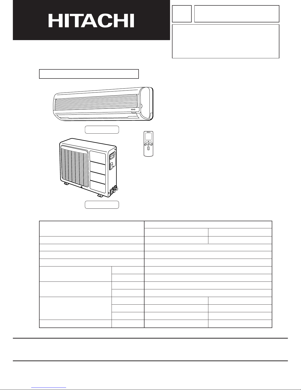
RAS-25CNH11
RAC-25CNH11
REFER TO THE FOUNDA TION MANUAL
INDOOR UNIT
RAS-25CNH11
OUTDOOR UNIT
RAC-25CNH11
WALL TYPE
SPECIFICATIONS AND PARTS ARE SUBJECT TO CHANGE FOR IMPROVEMENT
ROOM AIR CONDITIONER
INDOOR UNIT + OUTDOOR UNIT
JANUARY 2003
H.A.P.M.
TYPE
MODEL
1ø 220V 50HzPOWER SOURCE
910 (190 ` 1,150) [COOL] / 1,250 (160 ` 1,350) [HEAT]TOTAL INPUT
4.20 ` 3.85 [COOL] / 5.75 ` 5.25 [HEAT]TOTAL AMPERES (RATED / MAX.)
COOLING CAPACITY
HEATING CAPACITY
DIMENSIONS
NET WEIGHT
(W)
(A)
(kW)
(B.T.U ./h)
(kW)
(B.T.U ./h)
W
H
D
(kg)
(mm)
2.50 (0.90 ` 2.80)
8,870 (3,070 ` 9,550)
3.60 (0.90 ` 4.00)
12,280 (3,070 ` 13,650)
744
248
168
5.5
700
570
210
29
RAS-25CNH11
RAC-25CNH11
SAFETY DURING REPAIR WORK
1. In order to disassemble and repair
the unit in question, be sure to
disconnect the power cord plug
from the power outlet before starting
the work.
2. If it is necessary to replace any parts, they should be replaced with respective genuine parts for the unit, and
the replacement must be effected in correct manner according to the instructions in the Service Manual of
the unit.
If the contacts of electrical parts
are defective, replace the
electrical parts without trying to
repair them.
3. After completion of repairs, the initial state
should be restored.
4. Lead wires should be connected and laid as
in the initial state.
5. Modification of the unit by user himself should
absolutely be prohibited.
6. Tools and measuring instruments for use in repairs or inspection should be accurately calibrated in advance.
7. In installing the unit having been repaired, be careful to prevent the occurence of any accident such as
electrical shock, leak of current, or bodily injury due to the drop of any part.
8. To check the insulation of the unit, measure the insulation resistance between the power cord plug and
grounding terminal of the unit. The insulation resistance should be 1M or more as measured by a 500V
DC megger.
9. The initial location of installation such as window, floor or the other should be checked for being and safe
enough to support the repaired unit again.
If it is found not so strong and safe, the unit should be installed at the initial location reinforced or at a new
location.
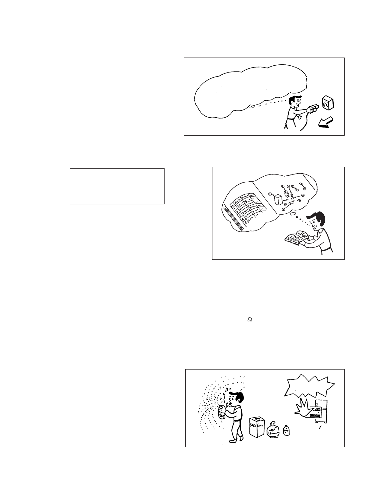
10. Any inflammable thing should never
be placed about the location of
installation.
11. Check the grounding to see whether
it is proper or not, and if it is found
improper, connect the grounding
terminal to the earth.
First, I must disconnect
the power cord plug
from the power outlet.
DANGER
– 1 –
WORKING STANDARDS FOR PREVENTING BREAKAGE OF SEMICONDUCTORS
1. Scope
The standards provide for items to be generally observed in carrying and handling semiconductors in relative
manufacturers during maintenance and handling thereof. (They apply the same to handling of abnormal goods
such as rejected goods being returned).
2. Object parts
(1) Micro computer
(2) Integrated circuits (IC)
(3) Field-effect transistors (FET)
(4) P.C. boards or the like on which the parts mentioned in (1) and (2) of this paragraph are equipped.
3. Items to be observed in handling
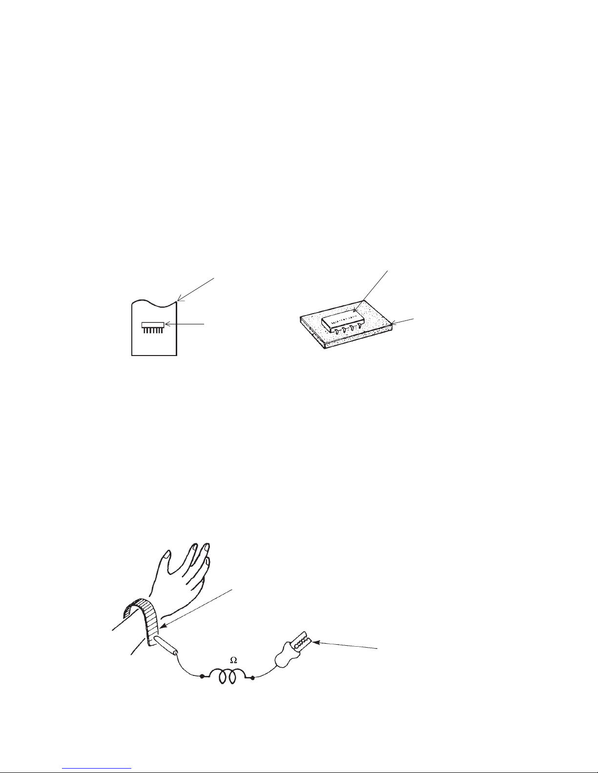
(1) Use a conductive container for carrying and storing of parts. (Even rejected goods should be handled in
the same way).
Fig. 1. Conductive Container
(2) When any part is handled uncovered (in counting, packing and the like), the handling person must always
use himself as a body earth. (Make yourself a body earth by passing one M ohm earth resistance through
a ring or bracelet).
(3) Be careful not to touch the parts with your clothing when you hold a part even if a body earth is being
taken.
(4) Be sure to place a part on a metal plate with grounding.
(5) Be careful not to fail to turn off power when you repair the printed circuit board. At the same time, try
to repair the printed circuit board on a grounded metal plate.
1M
Fig. 2. Body Earth
Body earth
(Elimik conductive band)
Clip for connection with a
grounding wire
IC
A conductive polyvinyl bag
IC
Conductive sponge
– 2 –
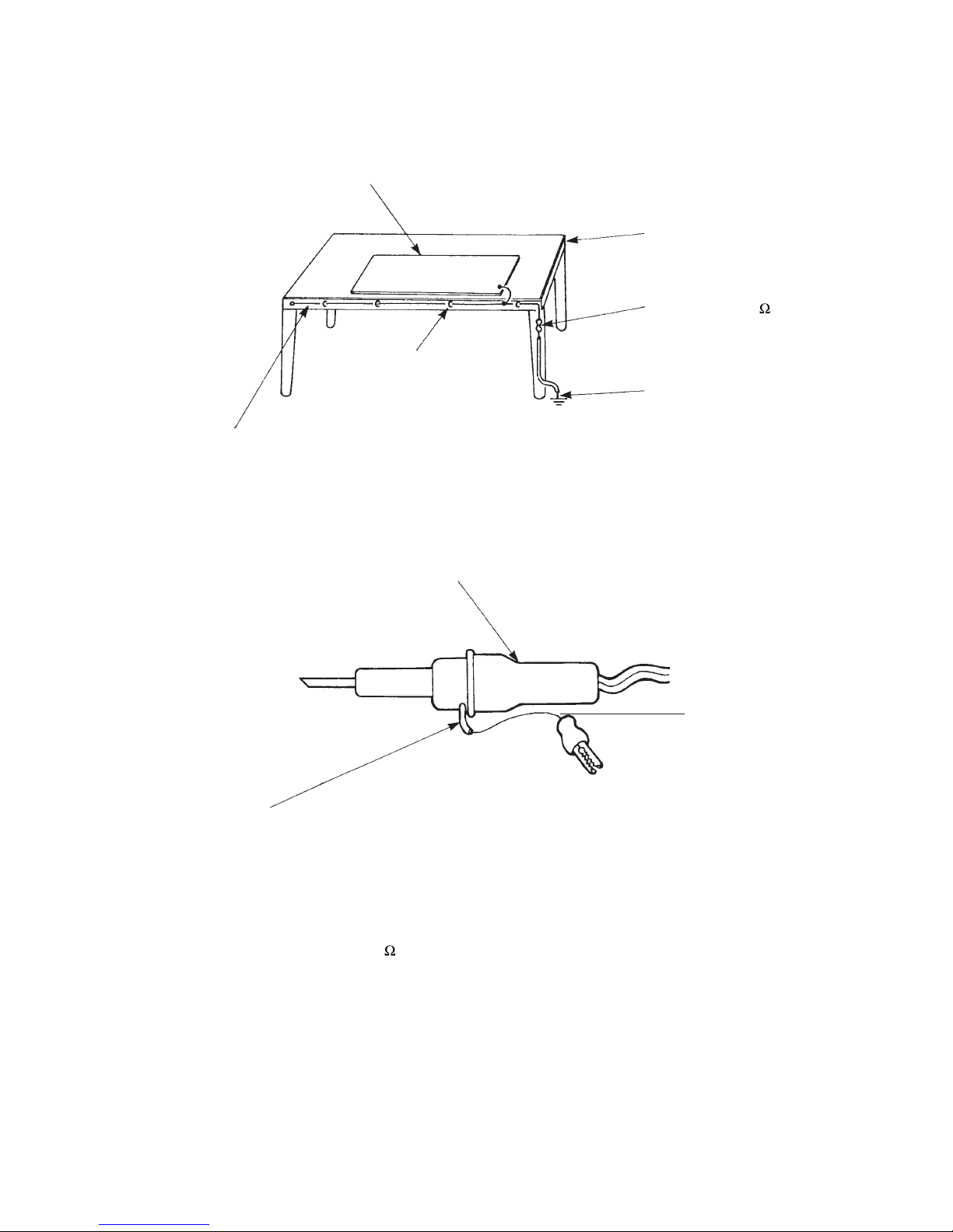
(6) Use a three wire type soldering iron including a grounding wire.
Bare copper wire (for body earth)
Working
table
Resistor of 1 M (1/2W)
Earth wire
Fig. 3. Grounding of the working table
2
Screw stop at the screwed
part using a rag plate
Soldering iron
Grounding
wire
Fig. 4. Grounding a soldering iron
Use a high insulation mode (100V, 10M or higher) when ordinary iron is to be used.
(7) In checking circuits for maintenance, inspection or some others, be careful not to have the test probes of the
measuring instrument shortcircuit a load circuit or the like.
Metal plate (of aluminium, stainless steel, etc.)
Staple

– 3 –
1. In quiet operation or stopping the running, slight flowing noise of refrigerant in the refrigerating cycle is heard
occasionally, but this noise is not abnormal for the operation.
2. When it thunders near by, it is recommend to stop the operation and to disconnect the power cord plug from
the power outlet for safety.
3. If the room air conditioner is stopped by setting the temperature or mis-operation, and then re-started in a
moment, cooling operation does not start for 3 minutes, it is not abnormal and this is the result of the
operation of IC delay circuit. This IC delay circuit ensures that there is no danger of blowing fuse or
damaging parts even if operation is restarted accidentally.
4. This room air conditioner should not be used at the cooling operation when the outside temperature is below
20°C.
5. When the operation knob is set to “COOL” from another position, IC delay circuit functions and stops the
compressor for the first 3 minutes, which is not an abnormal phenomenon.
CAUTION
– 4 –
RAS-25CNH11 RAC-25CNH11
MODEL
FAN MOTOR
FAN MOTOR CAPACITOR
FAN MOTOR PROTECTOR
COMPRESSOR
COMPRESSOR MOTOR CAPACITOR
OVERLOAD PROTECTOR
OVERHEAT PROTECTOR
FUSE
POWER RELAY, STICK RELAY
POWER SWITCH
TEMPORARY SWITCH
SERVICE SWITCH
TRANSFORMER
VARISTOR
NOISE SUPPRESSOR
REMOTE CONTROL SWITCH (LIQUID CRYSTAL)
THERMOSTAT
FUSE CAPACITY
SPECIFICATIONS
---------- ❈ 690g
UNIT
PIPES
❈ 690g for piping set of 5~8m.
REFRIGERANT
CHARGING VOLUME
(Refrigerant 22)
WITHOUT REFRIGERANT BECAUSE
COUPLING IS FLARE TYPE.
P - 105 VK1 (5m), P - 108 VK1 (8m)
20 W
NO
NO
NO GR20DR2F
----------
NO
YES
YES
3A
G4A
NO
NO
YES
NO
NO
NO
NO
YES
YES
NO
NO
416NR
YES
NO
NO
NO
NO
YES
YES (IC)
----------
16A INRUSH
WITHSTAND TYPE
– 5 –
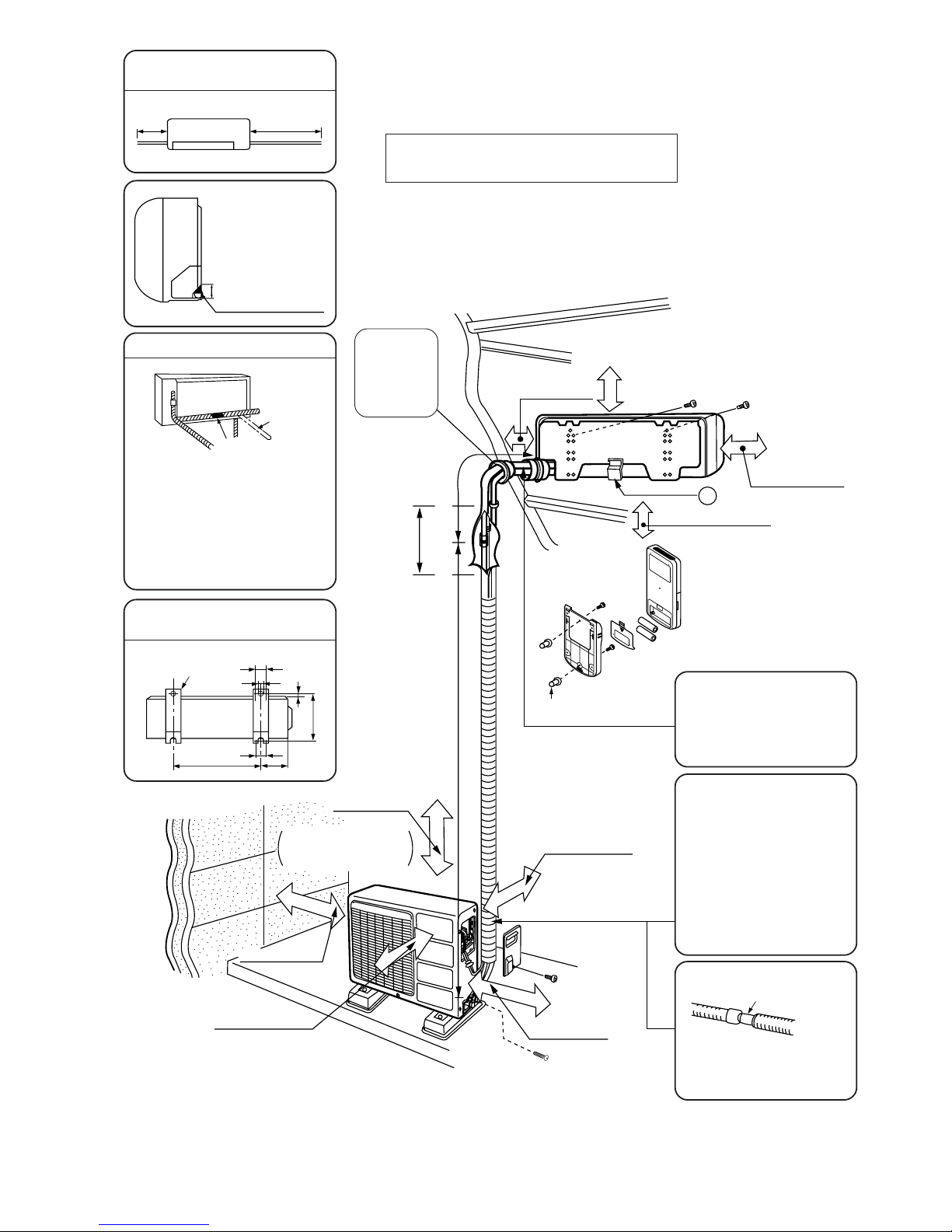
above 100mm
❈ above 300mm
above 200mm
❈ above 100mm
Maximum pipe length 8m
❈ give clearance
as wide as possible
above 50mm
above 100mm
about 0.45m
above 300mm
must not bend
above 100mm
Used in horizontal piping
6
above 50mm when
installed on the
ceiling of balcony
above 200mm
2,500mm or more
Plug
The Length of Indoor Unit Connecting
Cord
Figure showing the Installation of
Indoor and Outdoor Unit.
about 1.6m
about
0.9m
● The difference in height
between the indoor and outdoor
unit should be kept below 5m.
● The connecting pipe, no matter
big or small, should all be
insulated with insulation pipe
and then wrapped with vinyl
tape. (The insulator will
deteriorate if it is not wrapped
with tape).
The connection of insulated drain
hose.
Please use insulated drain hose
for the indoor piping (commercial
product).
inner diameter ø 16mm
The indoor piping should be
insulated with the enclosed
insulation pipe. (If the insulator is
insufficient, please use commersial
products).
Be sure to
completely
seal any gap
with putty.
Direction of Piping
Dimension of Mounting Stand
of the outdoor unit
500
100
35
35
12
225
8
mounting stand
(unit : mm)
There are 3 directions allowed,
namely, horizontally perpendicular to
the unit, vertically down from right,
horizontally out from right.
Don’t form the piping downward at the
left of the unit.
20
Cut away shaded
portion, and finish
the edge of the
opening so that
there is no burr.
Connection
Horizontally
perpendicular
to the unit
– 6 –
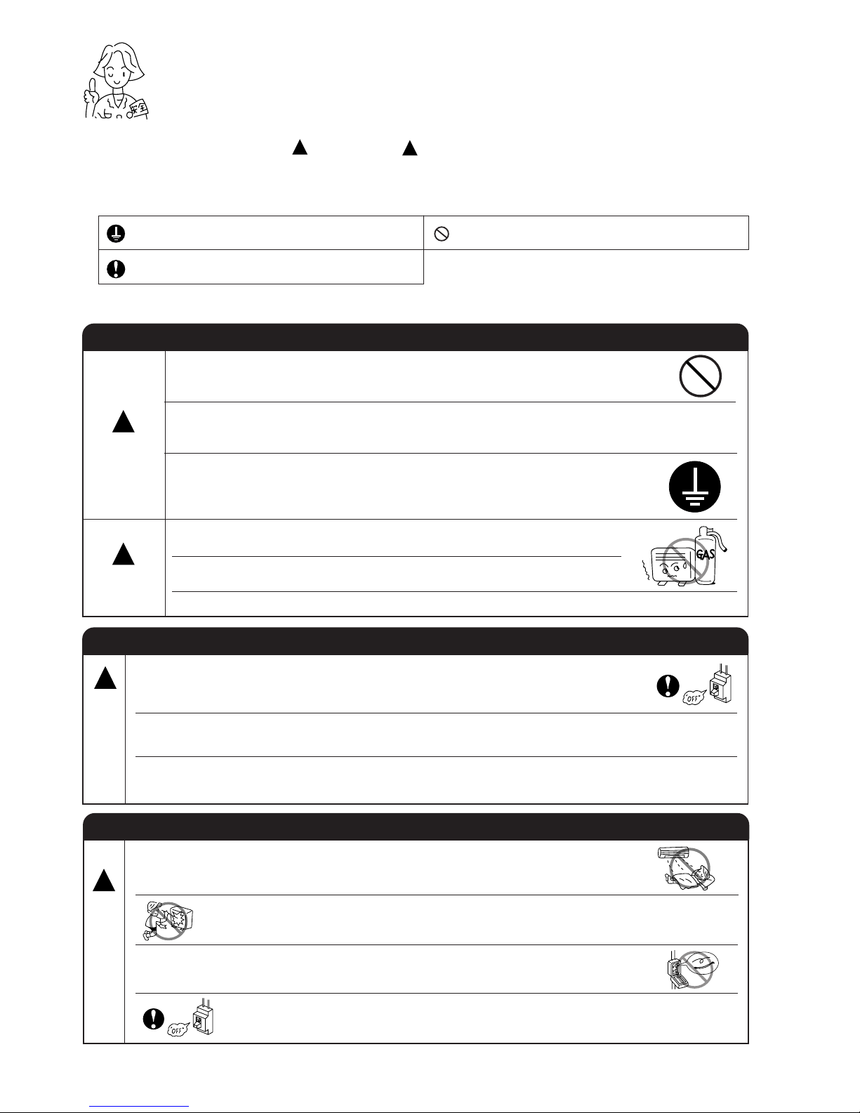
!
SAFETY PRECAUTION
●
Please read the “Safety Precaution” carefully before operating the unit to ensure correct usage of the unit.
●
Pay special attention to signs of “ Warning” and “ Caution”. The “Warning” section contains matters which,
if not observed strictly, may cause death or serious injury. The “Caution” section contains matters which may
result in serious consequences if not observed properly. Please observe all instructions strictly to ensure safety.
●
The sign indicate the following meanings.
●
Please keep this manual after reading.
WARNING
PRECAUTIONS DURING INSTALLATION
●
Do not reconstruct the unit.
Water leakage, fault, short circuit or fire may occur if you reconstruct
the unit by yourself.
●
Please ask your sales agent or qualified technician for the installation
of your unit. Water leakage, short circuit or fire may occur if you install
the unit by yourself.
●
Please use earth line.
Do not place the earth line near water or gas pipes, lightning-conductor,
or the earth line of telephone. Improper installation of earth line may
cause electric shock.
●
A circuit breaker should be installed depending on the mounting site of
the unit. Without a circuit breaker, the danger of electric shock exists.
●
Do not install near location where there is flammable gas. The outdoor
unit may catch fire if flammable gas leaks around it.
●
Please ensure smooth flow of water when installing the drain hose.
CAUTION
!
!
PRECAUTIONS DURING SHIFTING OR MAINTENANCE
PRECAUTIONS DURING OPERATION
●
Avoid an extended period of direct air flow for your health.
W
A
R
N
I
N
G
!
●
Should abnormal situation arises (like burning smell), please stop operating the unit
and turn off the circuit breaker. Contact your agent. Fault, short circuit or fire may
occur if you continue to operate the unit under abnormal situation.
●
Please contact your agent for maintenance. Improper self maintenance may cause
electric shock and fire.
●
Please contact your agent if you need to remove and reinstall the unit. Electric
shock or fire may occur if you remove and reinstall the unit yourself improperly.
●
Do not put objects like thin rods into the panel of blower and suction side
because the high-speed fan inside may cause danger.
●
During thunder storm, disconnect and turn off the circuit breaker.
●
Do not use any conductor as fuse wire, this could cause fatal accident.
!
Make sure to connect earth line.
Indicates the instructions that must be followed.
The sign in the figure indicates prohibition.
W
A
R
N
I
N
G
!
– 7 –
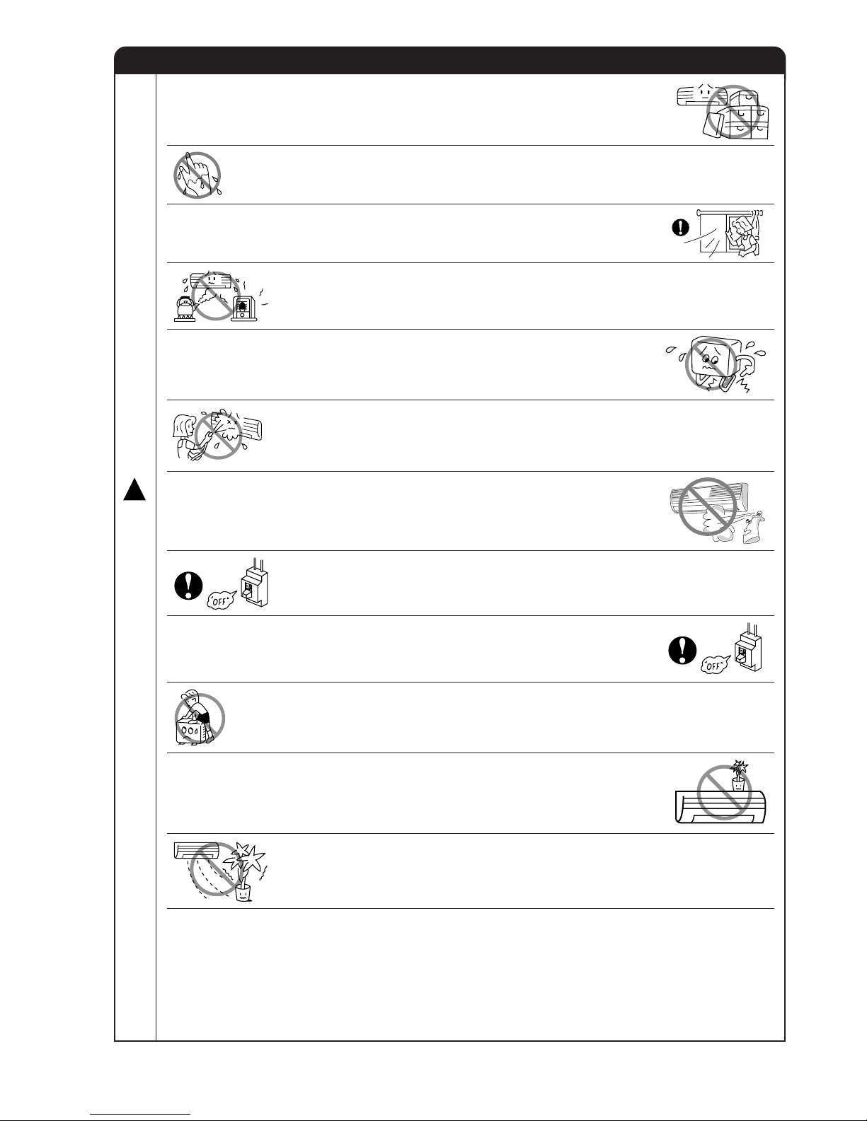
PRECAUTIONS DURING OPERATION
●
Do not attempt to operate the unit with wet hands, this could cause fatal
accident.
●
When operating the unit with burning equipments, regularly ventilate the
room to avoid oxygen insufficiency.
●
Do not direct the cool air coming out from the air-conditioner panel to face
household heating apparatus as this may affect the working of apparatus
such as the electric kettle, oven etc.
●
Do not place plants directly under the air flow as it is bad for the plants.
●
Please ensure that outdoor mounting frame is always stable, firm and
without defect. If not, the outdoor unit may collapse and cause danger.
●
Do not splash or direct water to the body of the unit when cleaning it as this
may cause short circuit.
●
When operating the unit with the door and windows opened, (the room humidity is always above
80%) and with the air deflector facing down or moving automatically for a long period of time,
water will condense on the air deflector and drips down occasionally. This will wet your furniture.
Therefore, do not operate under such condition for a long time.
●
If the amount of heat in the room is above the cooling or heating capability of the unit (for
example: more people entering the room, using heating equipments and etc.), the preset room
temperature cannot be achieved.
●
Do not climb on the outdoor unit or put objects on it.
●
Please switch off the unit and turn off the circuit breaker during cleaning, the
high-speed fan inside the unit may cause danger.
●
Turn off the circuit breaker if the unit is not to be operated for a long period.
C
A
U
T
I
O
N
!
●
The product shall be operated under the manufacturer specification and
not for any other intended use.
●
Do not put water container (like vase) on the indoor unit to avoid water
dripping into the unit. Dripping water will damage the insulator inside the unit
and causes short-circuit.
●
Do not use any aerosol or hair sprays near the indoor unit. This chemical
can adhere on heat exchanger fin and blocked the evaporation water flow
to drain pan. The water will drop on tangential fan and cause water splashing
out from indoor unit.
– 8 –
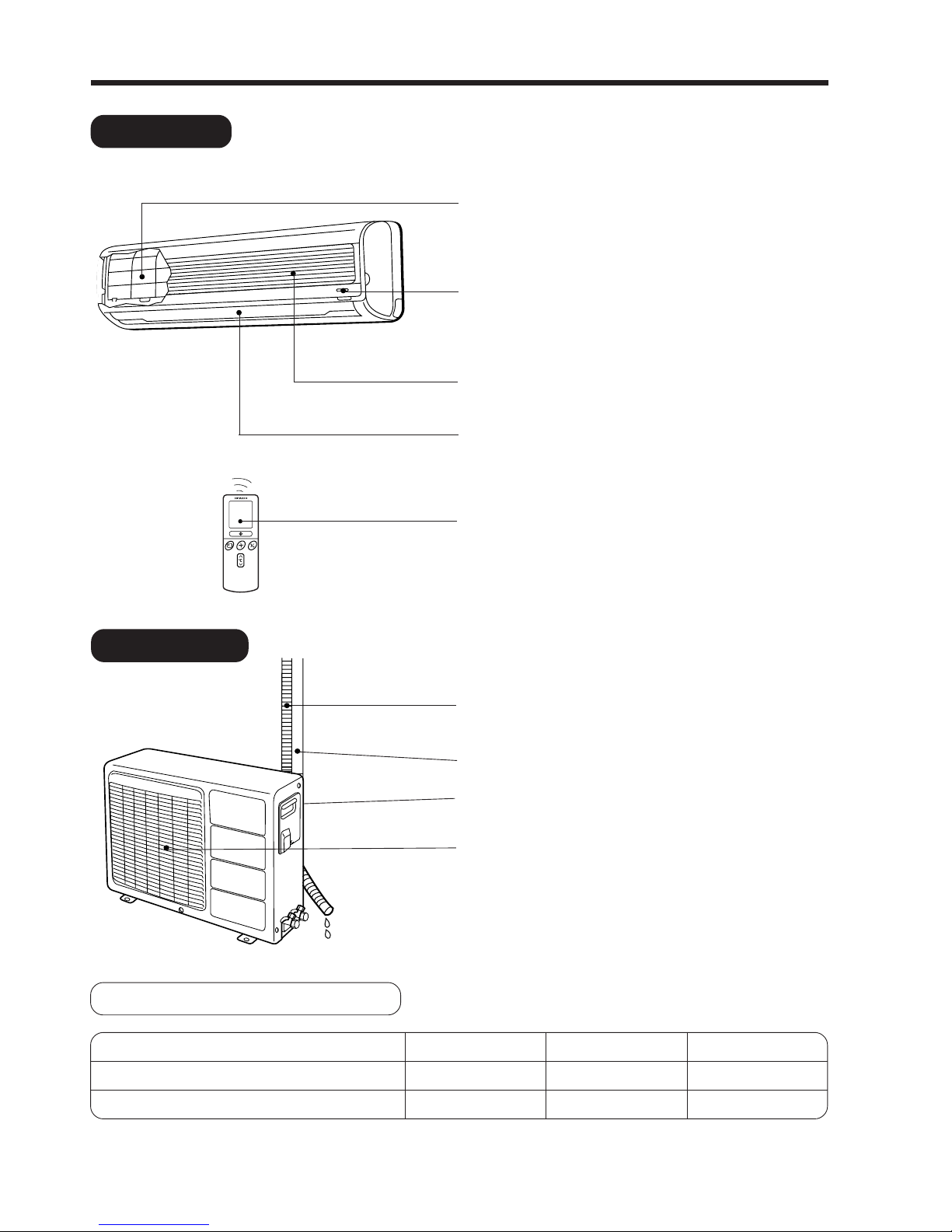
INDOOR UNIT
NAMES AND FUNCTIONS OF EACH PART
Air filter
To prevent dust from coming into the indoor unit.
(Refer page 25)
Indoor unit indicators
Light indicator showing the operating condition.
(Refer page 9)
Front panel (Air Inlet)
Horizontal deflector
●
Vertical deflector
(Air Outlet)
(Refer page 20)
Remote controller
Send out operation signal to the indoor unit. So as to
operate the whole unit.
(Refer page 10)
OUTDOOR UNIT
DRAIN PIPE
Condensed water drain to outside.
CONNECTING CORD
AIR INLET (BACK, LEFT SIDE)
AIR OUTLET
WIDTH (mm)
745
700
MODEL
RAS-25CNH11
RAC-25CNH11
HEIGHT (mm)
248
570
DEPTH (mm)
175
210
MODEL NAME AND DIMENSIONS
– 9 –
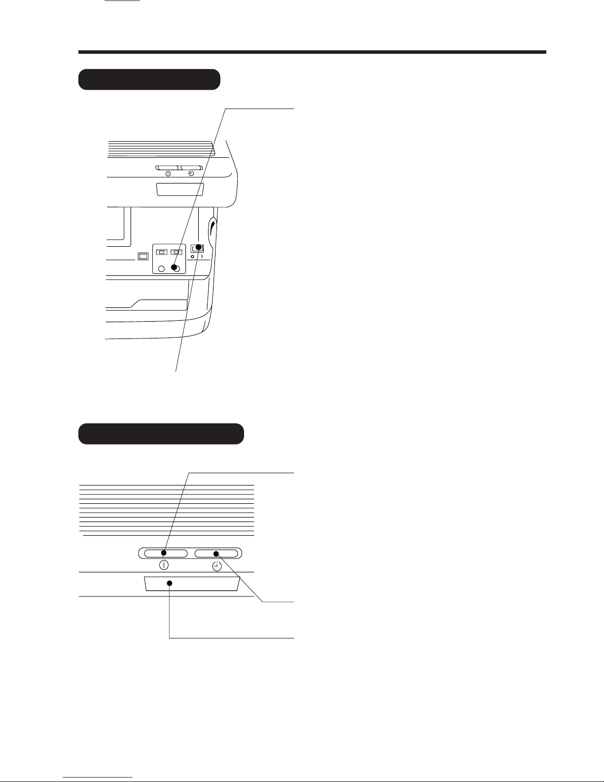
INDOOR UNIT INDICATORS
TEMPORARY SWITCH
Use this switch to start and stop when the remote
controller does not work.
● By setting the temporary switch, the operation is done
in previously set operation mode.
● When the operation is done using the temporary switch
after the power source is turned off and turn on again,
the operation is done in automatic mode.
OPERATION INDICATOR
OPERATION LAMP
This lamp lights during operation.
The OPERATION LAMP flashes in the following cases
during heating.
(1) During preheating
For about 2–3 minutes after starting up.
(2) During defrosting
Defrosting will be performed about once an hour
when frost forms on the heat exchanger of the
outdoor unit, for 5–10 minutes each time.
TIMER LAMP
This lamp lights when the timer is working.
SIGNAL RECEIVER
There will be a beep sound when this receiver receives
signal from remote controller.
POWER SWITCH
– 10 –
AUTO
HEAT
DEHUMIDIFY
COOL
FAN
FAN SPEED
LOW
MED
HI
SLEEPING
STOP (CANCEL)
START (RESERVE)
START/STOP
TIME
TIMER SET
TIMER SELECTOR
ON TIMER
OFF TIMER
AUTO SWING
˚
CH
RESET
˚
CH
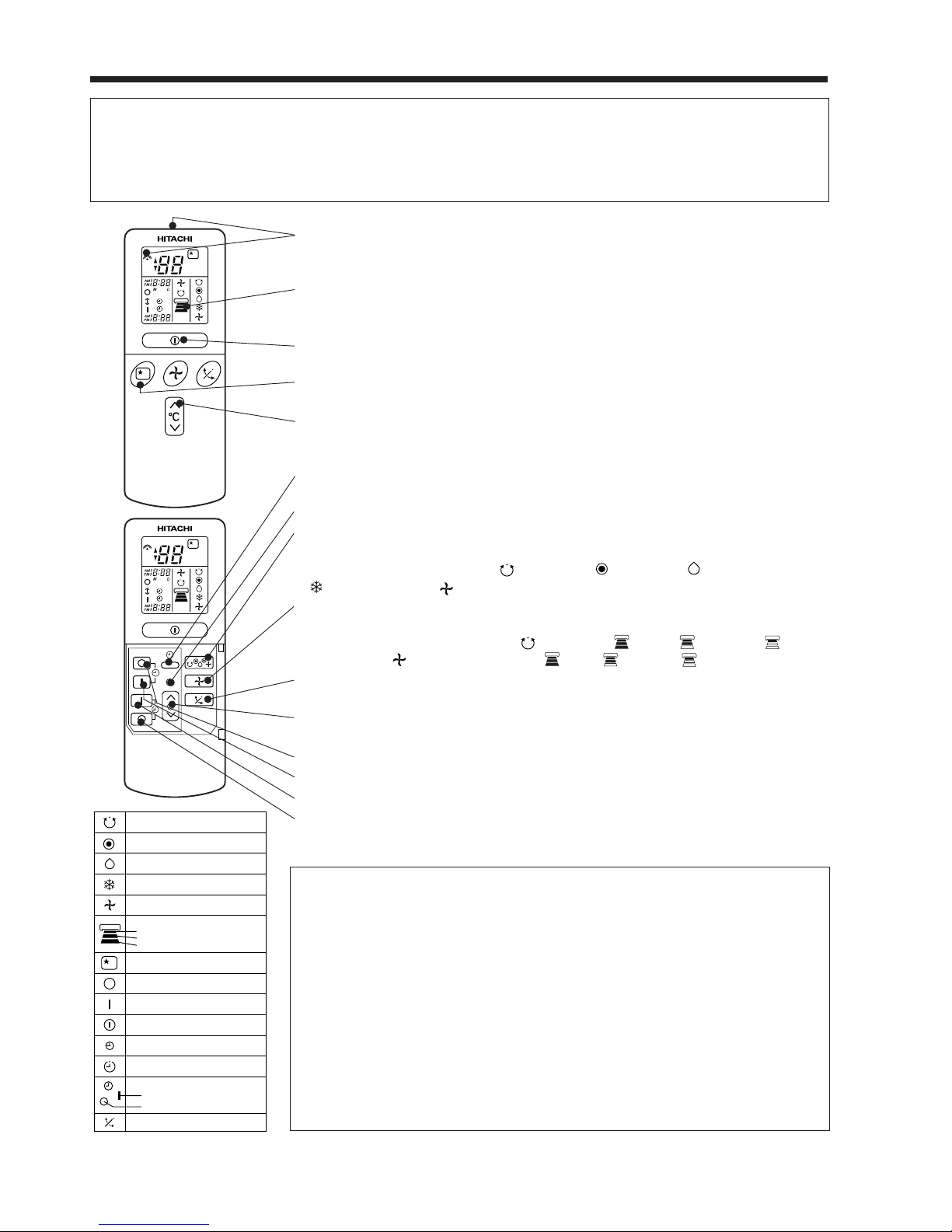
NAMES AND FUNCTIONS OF REMOTE CONTROL UNIT
REMOTE CONTROLLER
This controls the operation of the indoor unit. The range of control is about 7 meters. If indoor lighting
is controlled electronically, the range of control may be shorter.
This unit can be fixed on a wall using the fixture provided. Before fixing it, make sure the indoor unit can
be controlled from the remote controller.
● Signal emitting window/transmission sign
Point this window toward the indoor unit when controlling it.
The transmission sign blinks when a signal is sent.
● Display
This indicates the room temperature selected, current time, timer status,
function and intensity of circulation selected.
● START/STOP button
Press this button to start operation. Press it again to stop operation.
● SLEEP button
Use this button to set the sleep timer.
● TEMPERATURE buttons
Use these buttons to raise or lower the temperature setting. (Keep pressed,
and the value will change more quickly.)
● TIME button
Use this button to set and check the time and date.
● RESET buttons
● FUNCTION selector
Use this button to select the operating mode. Every time you press it,
the mode will change from (AUTO) to (HEAT) to (DEHUMIDIFY) to
(COOL) and to (FAN) cyclically.
● FAN SPEED selector
This determines the fan speed. Every time you press this button, the intensity
of circulation will change from (AUTO) to (HI) to (MED) to (LOW)
(during the (FAN) mode, from HI to MED to LOW).
● AUTO SWING button
Controls the angle of the horizontal air deflector.
● TIMER control
Use this button to set the timer.
● OFF-TIMER button Select the turn OFF time.
● ON-TIMER button Select the turn ON time.
● RESERVE button Time setting reservation.
● CANCEL button Cancel time reservation.
Precautions for Use
● Do not put the remote controller in the following places.
● Under direct sunlight.
● In the vicinity of a heater.
● Handle the remote controller carefully. Do not drop it on the floor,
and protect it from water.
● Once the outdoor unit stops, it will not restart for about 3 minutes
(unless you turn the power switch off and on or unplug the power
cord and plug it in again).
This is to protect the device and does not indicate a failure.
● If you press the FUNCTION selector button during operation, the
device may stop for about 3 minutes for protection.
– 11 –
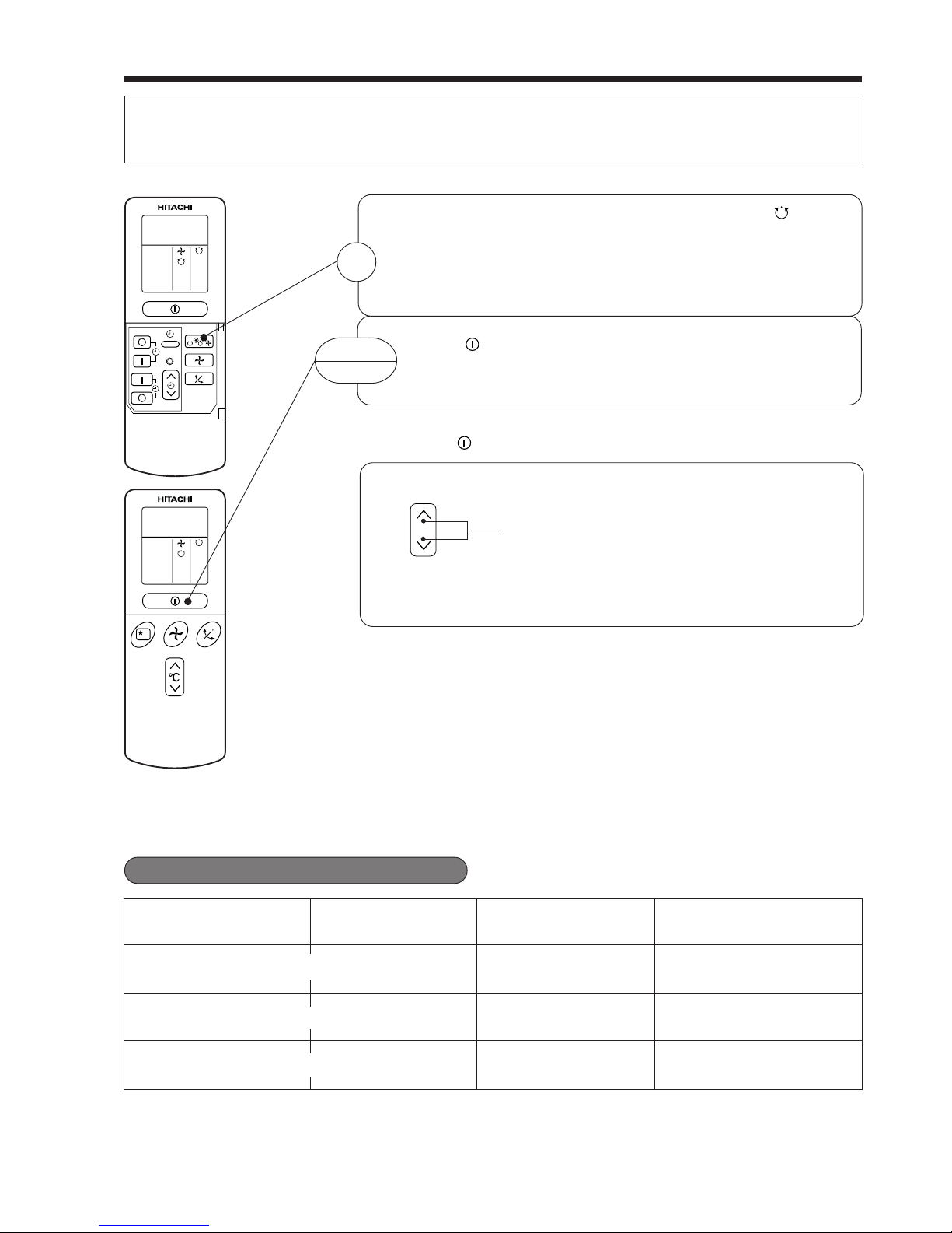
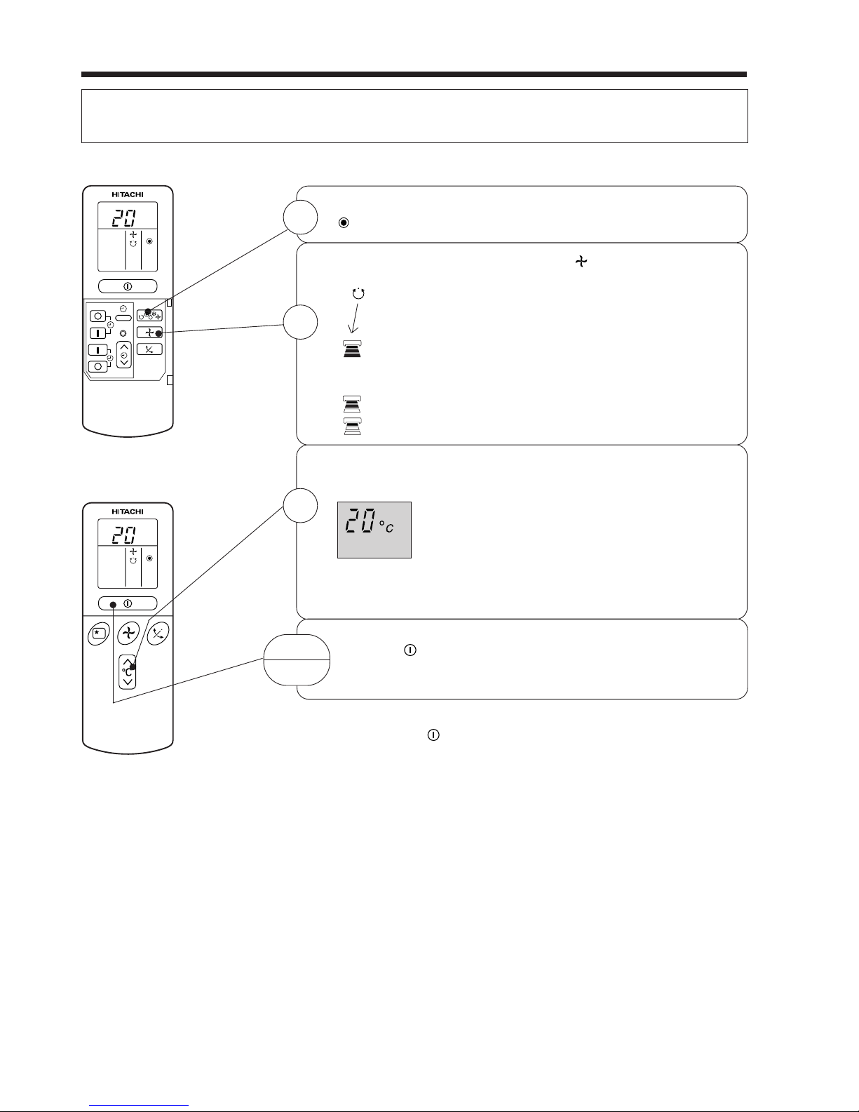
AUTOMATIC OPERATION
The device will automatically determine the mode of operation, HEAT, COOL or DEHUMIDIFY depending on
the initial room temperature. The selected mode of operation will not change when the room temperature
varies.
■ As the settings are stored in memory in the remote controller, you only have
to press the (START/STOP) button next time.
Press the FUNCTION selector so that the display indicates the (AUTO)
mode of operation.
● When AUTO has been selected, the device will automatically determine
the mode of operation, HEAT, COOL or DEHUMIDIFY depending on
the initial room temperature.
Press the (START/STOP) button.
Operation starts with a beep.
Press the button again to stop operation.
You can raise or lower the temperature setting as necessary by maximum of
3°C.
Press the temperature button and the temperature setting
will change by 1°C each time.
● The preset temperature and the actual room temperature may vary
somewhat depending on conditions.
● The display does not indicate the preset temperature in the AUTO mode.
If you change the setting, the indoor unit will produce a beep.
1
START
STOP
°C
RESET
Over 27°C COOL
23~27°C
Under 23°C HEAT
Temperature settingFunction
27°C
23°C
Slightly lower than the
room temperature
LOW
FAN SPEED
HI at start, MED or LOW
after the preset temperature
is reached
HI at start, MED or LOW
after the preset temperature
is reached
-
-
DEHUMIDIFY
-
Initial room temperature
(approx.)
■ Condition of Automatic Operation
– 12 –
HEATING OPERATION
● Use the device for heating when the outdoor temperature is under 21°C.
When it is too warm (over 21°C), the heating function may not work in order to protect the device.
Press the FUNCTION selector so that the display indicates
(HEAT).
Set the desired FAN SPEED with the (FAN SPEED) button
(the display indicates the setting).
(AUTO): The fan speed is HI at first and varies to MED
automatically when the preset temperature has
been reached.
(HI) : Economical as the room will become warm
quickly.
But you may feel a chill at the beginning.
(MED) : Quiet.
(LOW) : More quiet.
Set the desired room temperature with the TEMPERATURE
buttons (the display indicates the setting).
The range of 18-22°C is recommended as the
room temperature for heating.
If the temperature setting is 20°C, the room
temperature will be controlled at around 20°C.
The temperature setting and the actual room temperature may
vary somewhat depending on conditions.
Press the (START/STOP) button. Heating operation starts
with a beep. Press the button again to stop operation.
■ As the settings are stored in memory in the remote controller, you only
have to press the (START/STOP) button next time.
1
2
3
START
STOP
˚
C
RESET
˚
C
– 13 –
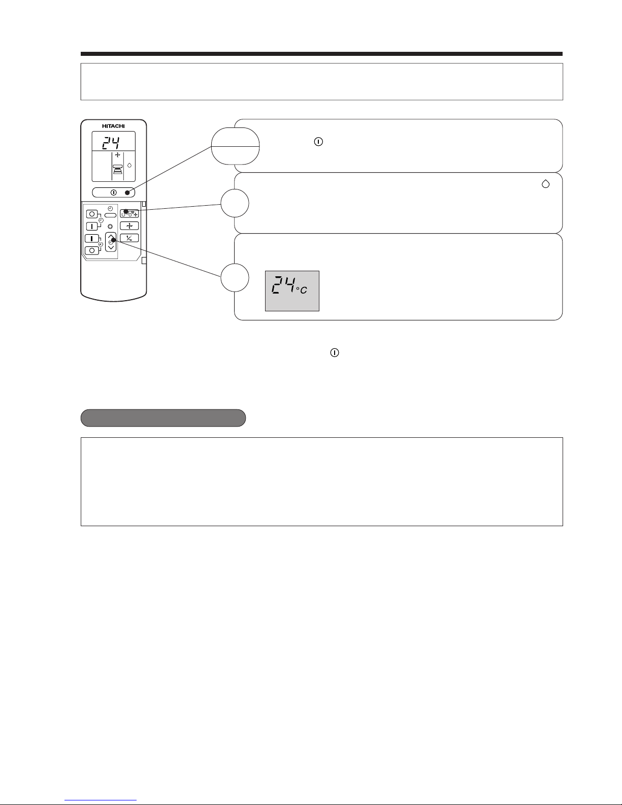
Set the desired room temperature with the TEMPERATURE
button (the display indicates the setting).
The range of 20-26˚C is recommended as the
room temperature for dehumidifying.
DEHUMIDIFYING OPERATION
Use the device for dehumidifying when the room temperature is over 16°C.
When it is under 15°C, the dehumidifying function will not work.
Press the (START/STOP) button. Dehumidifying operation
starts with a beep. Press the button again to stop operation.
2
■ Dehumidifying Function
When the room temperature is higher than the temperature setting: The device will dehumidify the room,
reducing the room temperature to the preset level.
When the room temperature is lower than the temperature setting: Dehumidifying will be performed at
the temperature setting slightly lower than the current room temperature, regardless of the temperature
setting. The function will stop (the indoor unit will stop emitting air) as soon as the room temperature
becomes lower than the setting temperature.
■ As the settings are stored in memory in the remote controller, you only
have to press the
(START/STOP) button next time.
START
STOP
Press the FUNCTION selector so that the display indicates
(DEHUMIDIFY).
The FAN SPEED is set at LOW automatically.
The FAN SPEED button does not work.
1
RESET
˚
C
– 14 –
˚
C
RESET
˚
C
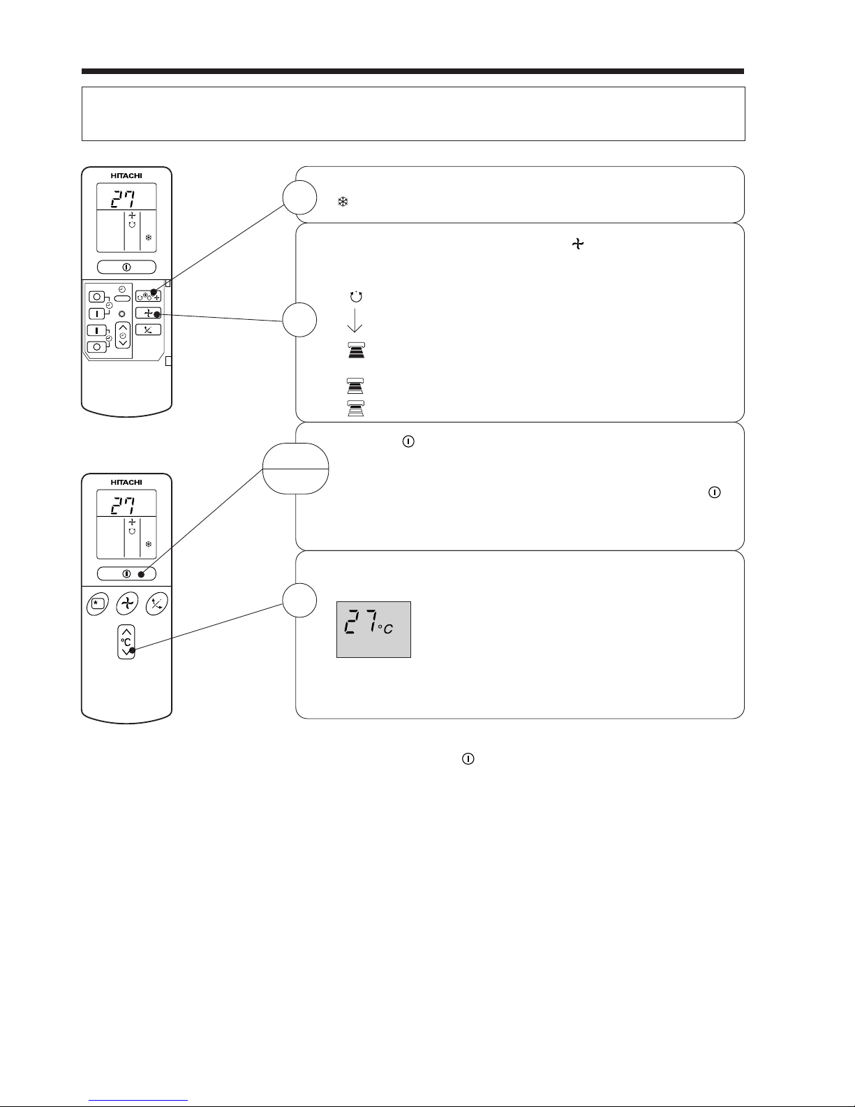
COOLING OPERATION
Use the device for cooling when the outdoor temperature is 22-42°C.
If in doors humidity is very high (80%), some dew may form on the air outlet grille of the indoor unit.
Press the FUNCTION selector so that the display indicates
(COOL).
Set the desired FAN SPEED with the
(FAN SPEED) button
(the display indicates the setting).
(AUTO): The FAN SPEED is HI at first and varies to
MED automatically when the preset temperature
has been reached.
(HI) : E conomical as the room will become cool
quickly.
(MED) : Quiet.
(LOW) : More quiet.
Press the
(START/STOP) button. Cooling operation starts
with a beep. Press the button again to stop operation. The
cooling function does not start if the temperature setting is
higher than the current room temperature (even though the
(OPERATION) lamp lights). The cooling function will start as
soon as you set the temperature below the current room
temperature.
Set the desired room temperature with the TEMPERATURE
button (the display indicates the setting).
The range of 25-28°C is recommended as the
room temperature for cooling.
If the temperature setting is 27°C, the room
temperature will be controlled at around 27°C.
The temperature setting and the actual room temperature may
vary some how depending on conditions.
■ As the settings are stored in memory in the remote controller, you
only have to press the
(START/STOP) button next time.
1
2
START
STOP
3
– 15 –
* Note • In the fan operation mode, only display of FAN SPEED
setting will change by pressing FAN SPEED button; the
actual fan speed cannot be changed directly from HI to
LOW mode.
FAN SPEED (AUTO)
.....
When the AUTO fan speed mode is set in the cooling/heating operation:
For the heating operation
● The fan speed will automatically change according to the temperature
of discharged air.
● When the difference of room temperature and setting temperature is
large, fan starts to run at HI speed.
● When the room temperature reaches setting temperature, fan speed
changes to LOW automatically.
● When the difference of room temperature and setting temperature is
large, fan starts to run at HI speed.
● After room temperature reaches the preset temperature, the cooling
operation, which changes the fan speed and room temperature to obtain
optimum conditions for natural healthful cooling will be performed.
For the cooling operation
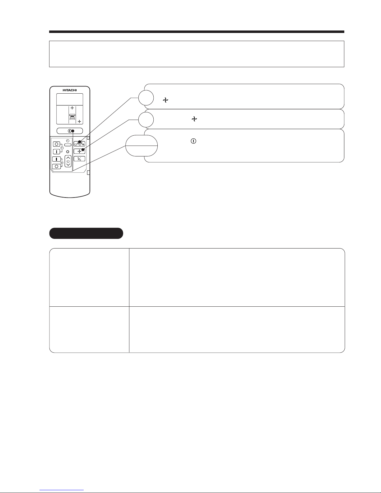
FAN OPERATION
You can use the device simply as an air circulator. Use this function to dry the interior of the indoor
unit at the end of summer.
Press the FUNCTION selector so that the display indicates
(FAN).
Press the (FAN SPEED) button.*
Press the (START/STOP) button. Fan operation starts with
a beep. Press the button again to stop operation.
1
2
START
STOP
RESET
– 16 –
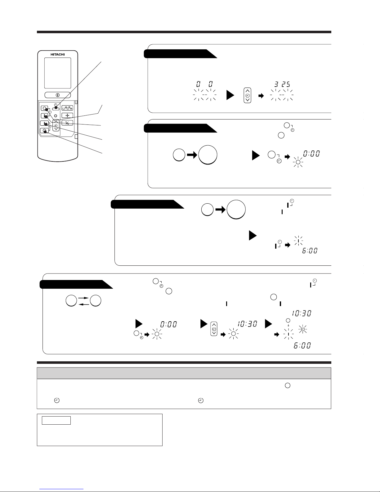
HOW TO SET THE TIMER
ON/OFF-Timer
● The device will turn on (off) and off
(on) at the designated times.
● The switching occurs first at the
preset time that comes earlier.
● The arrow mark appearing on the
display indicates the sequence of
switching operations.
1
Press the (ON-OFF)
button so that the (OFF)
mark blinks.
OFF-Timer
You can set the device to turn off
at the present time.
After you change the
batteries;
How to Cancel Reservation
Point the signal window of the remote controller toward the indoor unit, and press the (CANCEL)
button.
The (RESERVED) sign goes out with a beep and the (TIMER) lamp turns off on the indoor unit.
1
Set the current month and
day with the TIMER control
button.
1
Press the (OFF-TIMER)
button. The (OFF) mark blinks
on the display.
1
Press the (ON-TIMER)
button the (ON) mark blinks
on the display.
2
Set the turn-off time
with the TIMER control
button.
Press the (RESERVE)
button.
3
Press the (ON-
TIMER) button so that the
(OFF) mark lights and
the (ON) mark blinks.
NOTE
You can set only one of the OFF-timer,
ON-timer and ON/OFF-timer.
ON-Timer
Time, Day, Month
● The device will turn on
at the designated times.
TIME, DAY,
MONTH
(current time,
day, month)
OFF TIMER
ON TIMER
RESERVE
CANCEL
M D
M D
AM
STOP
Start
AM
Start
Stop
PM
Start Stop
PM
AM
PM
RESET
– 17 –
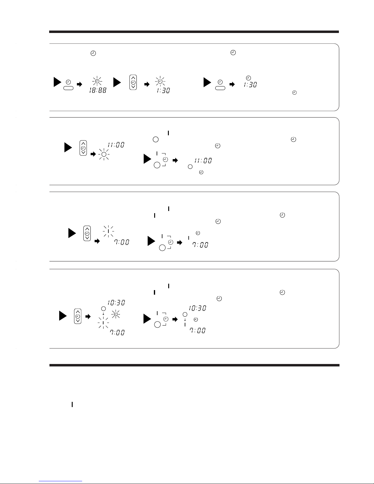
3
Point the signal window of the remote controller toward the indoor unit, and
press the (RESERVE) button.
The (OFF) mark starts lighting instead of flashing and the sign (RESERVED)
lights. A beep occurs and the (TIMER) lamp lights on the indoor unit.
● The time indication will disappear
automatically in 10 second.
● To check the current time setting,
press the (TIME) button twice.
The setting of the current time is
now complete.
● The timer may be used in three ways: off-timer, on-timer, and ON/OFF (OFF/ON)-timer. Set
the current time at first because it serves as a reference.
● As the time settings are stored in memory in the remote controller, you only have to press
the (RESERVE) button in order to use the same settings next time.
2
Press the
(TIME) button.
3
Set the current time with the
TIMER control button.
Example: The current time is 1:30 p.m.
2
Set the turn-off time with the
TIMER control button.
The setting of turn-off time is now complete.
Example: The device will turn off at 11:00p.m.
Example:
The device will automatically turn on earlier so that the preset
temperature can be reached at 7:00 a.m.
The setting of the turn-on time is now complete.
4
Set the turn-on time with the
TIMER control button.
5
Point the signal window of the remote controller toward the indoor unit, and
press the (RESERVE) button.
The (ON) mark starts lighting instead of flashing and the (RESERVED) sign
lights. A beep occurs and the (TIMER) lamp lights on the indoor unit.
3
Point the signal window of the remote controller toward the indoor unit, and
press the (RESERVE) button.
The (ON) mark starts lighting instead of flashing and the (RESERVED) sign
lights. A beep occurs and the (TIMER) lamp lights on the indoor unit.
2
Set the turn-on time with the
TIMER control button.
Example:
The device will turn off at 10:30 p.m. and then automatically
turn on earlier so that the preset temperature can be reached
at 7:00 a.m.
The settings of the turn-on/off times are now complete.
4
Press the (TIME) button again.
The time indication starts lighting
instead of flashing.
PM PM
AM
PM
PM
PM
AM
AM
AM
AM
PM
PM
– 18 –
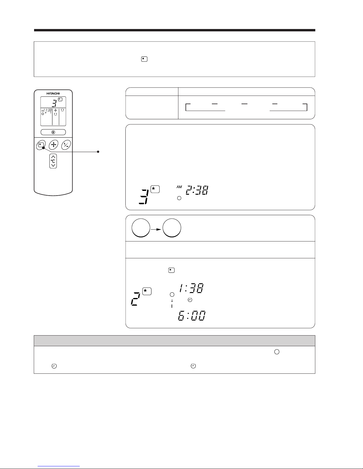
HOW TO SET THE SLEEP TIMER
1
Set the ON-timer.
Set the current time at first if it is not set before (see the pages for setting
the current time). Press the (SLEEP) button, and the display changes as
shown below.
Mode
Sleep timer
Indication
1 hour 2 hours 3 hours 7 hours
Sleep timer off
44 44
1
Sleep Timer: The device will continue working for the designated
number of hours and then turn off.
Point the signal window of the remote controller toward the indoor
unit, and press the SLEEP button.
The timer information will be displayed on the remote controller.
The TIMER lamp lights with a beep from the indoor unit. When the
sleep timer has been set, the display indicates the turn-off time.
Example: If you set 3 hours sleep
time at 11:38 p.m., the turn-off
time is 2:38 a.m.
2
Press the (SLEEP) button and set the sleep timer.
The device will be turned off by the sleep
timer and turned on by on-timer.
How to Cancel Reservation
Point the signal window of the remote controller toward the indoor unit, and press the (CANCEL)
button.
The (RESERVED) sign goes out with a beep and the (TIMER) lamp turns off on the indoor unit.
For heating:
In this case, the device will turn off
in 2 hours (at 1:38 a.m.) and turn
on early so that the preset
temperature will be almost reached
at 6:00 next morning.
SLEEP
H
H
AM
AM
Sleep
timer
Start
H
– 19 –
Cooling
“ ”
and
dehumidifying
“ ”
Explanation of the sleep timer
The device will control the FAN SPEED and room temperature automatically
so as to be quiet and good for people’s health.
You can set the sleep timer to turn off after 1, 2, 3 or 7 hours. The FAN
SPEED and room temperature will be controlled as shown below.
Function Operation
The settings of room temperature and circulation are varied.
The room temperature will be
controlled 2°C above the
temperature and the FAN
SPEED will be set to LOW
setting 30 minutes after the
setting of the sleep timer.
Fan
“ ”
Heating
“ ”
The room temperature will be
controlled 5°C below the
temperature and the FAN
SPEED will be set to LOW
setting 30 minutes after the
setting of the sleep timer.
Operation with the sleep timer
Sleep timer set
30 minutes later
1 hour later
3 hours later
7 hours
later
2 hours
later
5°C
● If date or current time is not set, sleep timer can not be set.
● If you set the sleep timer after the off-, on/off- or off/on-timer has been set, the sleep timer
becomes effective instead of the off-, on/off- or off/on-timer set earlier.
● You can not set other timer during sleep timer operation.
● After sleep timer time is up and when press sleep button again, the sleep timer will be set as
last setting.
● Sleep timer effective only once.
NOTE
Sleep
timer set
30 minutes later
3 hours later
7 hours later
2 hours
later
6 hours
later
2°C
– 20 –
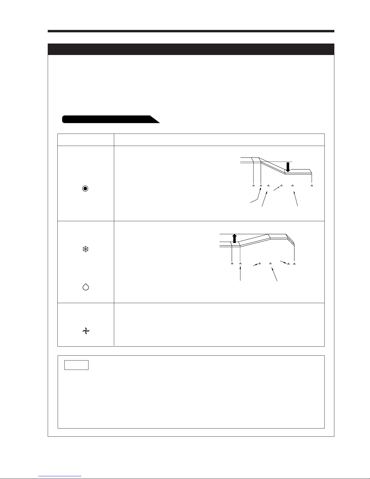
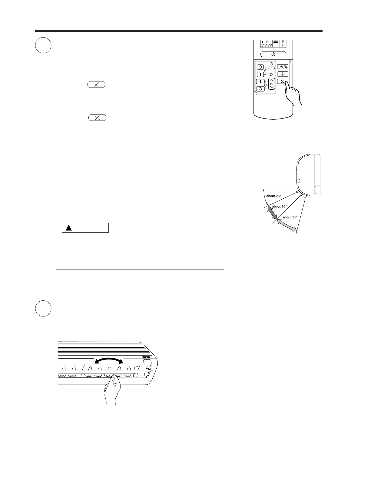
ADJUSTING THE AIR DEFLECTOR
1
2
Adjustment of the conditioned air to the left and right.
Hold the vertical air deflector as shown in the figure and adjust
the conditioned air to the left and right.
● If the “ (AUTO SWING)” button is pressed once,
the horizontal air deflector swings up and down. If the
button is pressed again, the deflector stops in its current
position. Several seconds (about 6 seconds) may be
required before the deflector starts to move.
● Use the horizontal air deflector within the adjusting range
shown on the right.
● When the operation is stopped, the horizontal air deflector
moves and stops at the position where the air outlet
closes.
When cooling
dehumidifying
When heating
!
CAUTION
● In “Cooling” operation, do not keep the horizontal air
deflector swinging for a long time. Some dew may form
on the horizontal air deflector and some dew drops may
fall from it.
RESET
Adjustment of the conditioned air in the upward and downward
directions.
The horizontal air deflector is automatically set to the proper
angle suitable for each operation. The deflector can be swung
up and down continuously and also set to the desired angle
using the “ (AUTO SWING)” button.
– 21 –
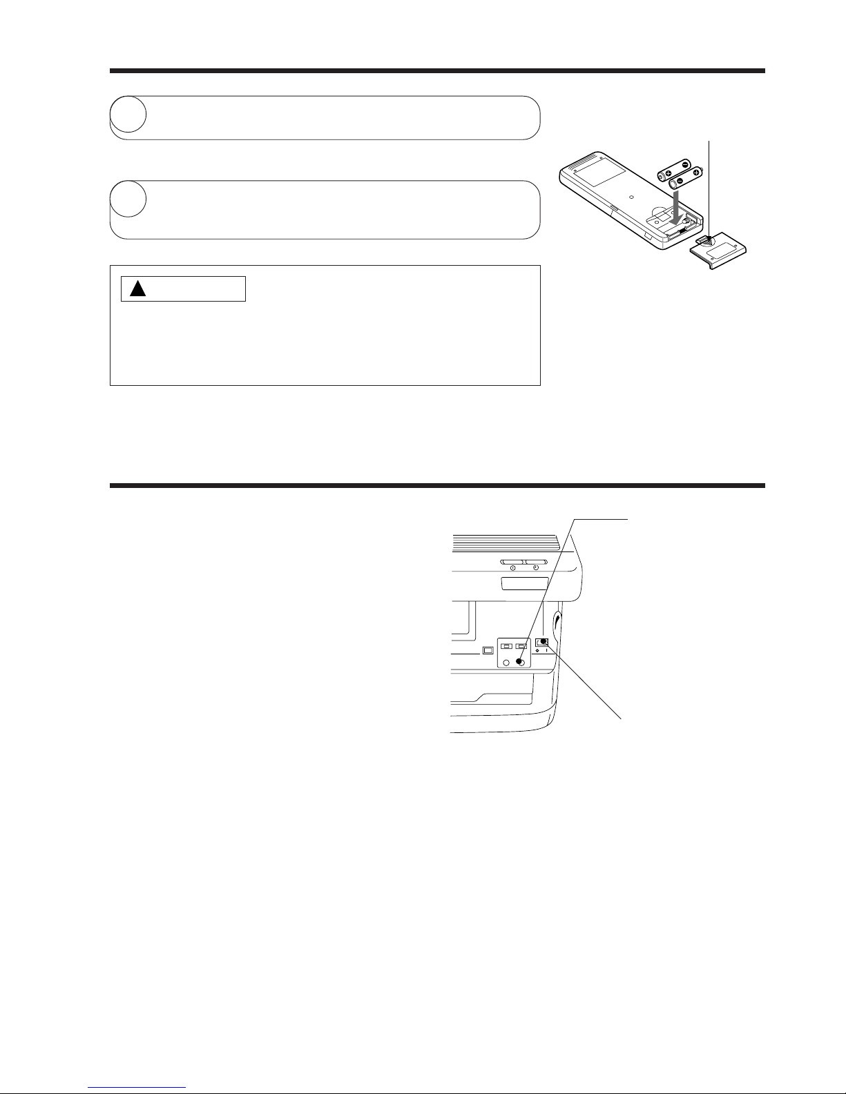
HOW TO EXCHANGE THE BATTERIES IN THE REMOTE CONTROLLER
1
Remove the cover as shown in the figure and take out the
old batteries.
=
2
Install the new batteries.
The direction of the batteries should match the marks in the
case.
1. Do not use new and old batteries, or different kinds of batteries
together.
2. Take out the batteries when you do not use the remote controller
for 2 or 3 months.
CAUTION
!
Push and pull to the
direction of arrow
TEMPORARY SWITCH
Use this switch to start and stop when the
remote controller does not work.
● By setting the temporary switch, the
operation is done in previously set operation
mode.
● When the operation is done using the
temporary switch after the power source is
turned off and turn on again, the operation
is done in automatic mode.
POWER SWITCH
TEMPORARY SWITCH
– 22 –
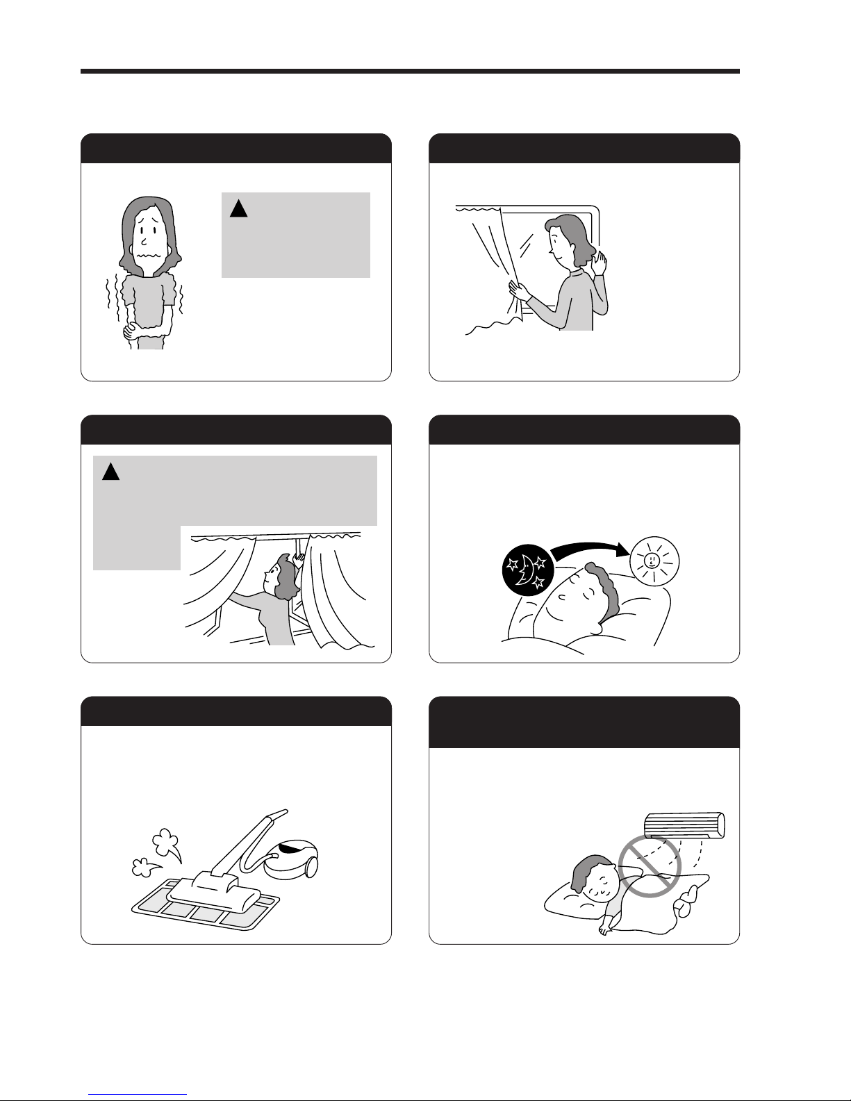
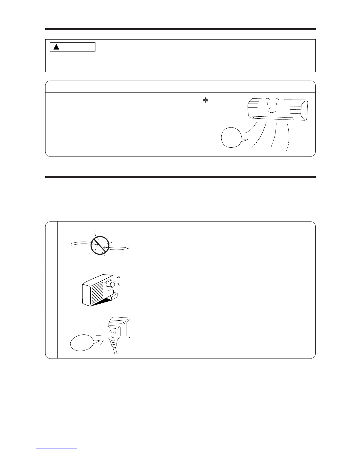
Suitable Room Temperature Install curtain or blinds
Ventilation Effective Usage Of Timer
Do Not Forget To Clean The Air Filter
Please Adjust Suitable Temperature
For Baby And Children
Warning
Freezing temperature
is bad for health and a
waste of electric power.
!
It is possible to
reduce heat
entering the
room through
windows.
At night, please use the “OFF or ON timer
operation mode”, together with your wake up
time in the morning. This will enable you to
enjoy a comfortable room temperature. Please
use the timer effectively.
Dusty air filter will reduce the air volume and
the cooling efficiency. To prevent from wasting
electric energy, please clean the filter every 2
weeks.
Please pay attention to the room temperature
and air flow direction when operating the unit
for baby, children and old folks who have
difficulty in movement.
Caution
Do not close the room for a long period of
time. Occasionally open the door and windows
to allow the
entrance of
fresh air.
!
THE IDEAL WAYS OF OPERATION
– 23 –
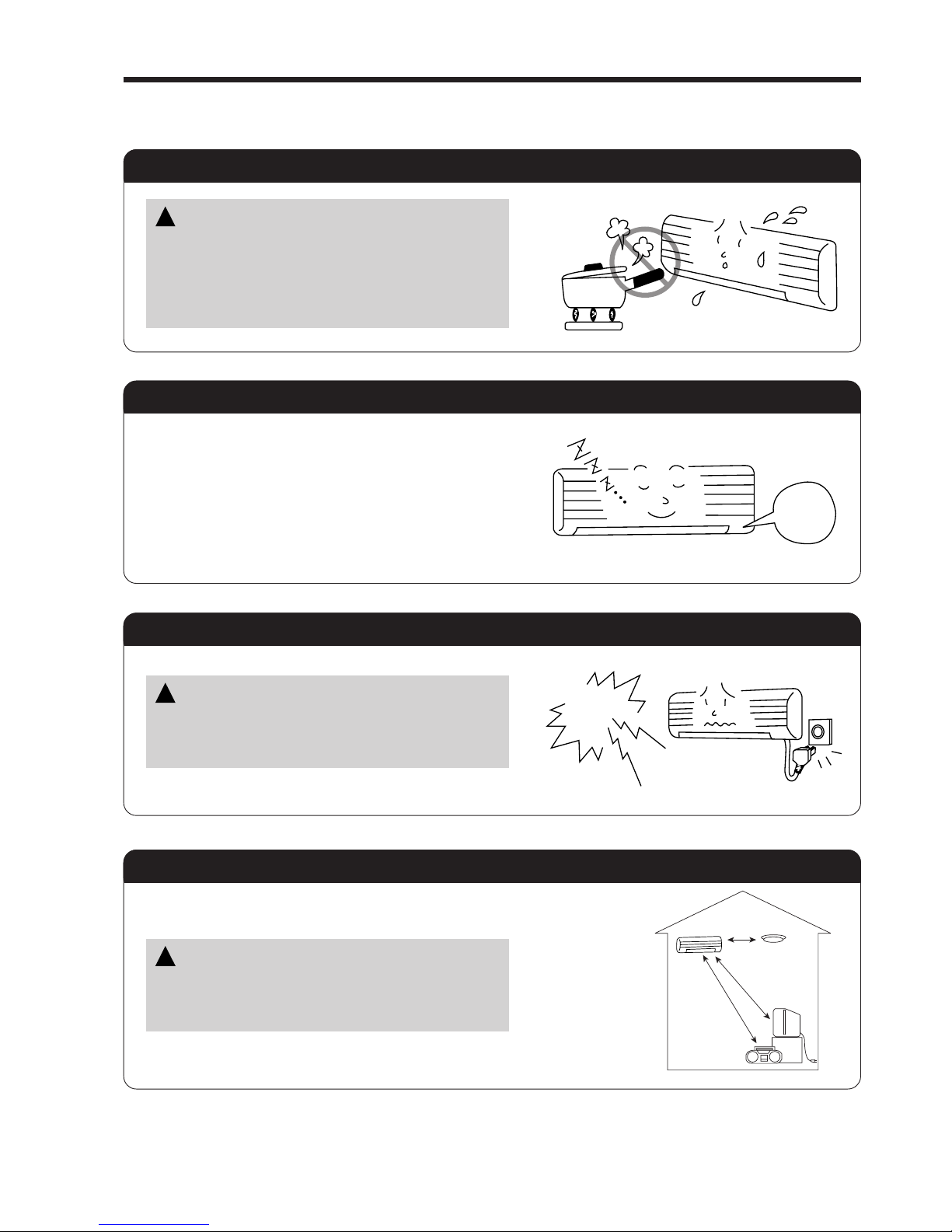
FOR USER’S INFORMATION
The Air Conditioner And The Heat Source In The Room
Not Operating For A Long Time
When Lightning Occurs
Caution
If the amount of heat in the room is above the cooling
capability of the air conditioner (for example: more
people entering the room, using heating equipments
and etc.), the preset room temperature cannot be
achieved.
!
When the indoor unit is not to be used for a long
period of time, please switch off the power from the
mains. If the power from mains remains “ON”, the
indoor unit still consumes about 8W in the operation
control circuit even if it is in “OFF” mode.
Warning
To protect the whole unit during lightning, please
stop operating the unit and remove the plug from the
socket.
!
OFF
Interference From Electrical Products
Caution
To avoid noise interference, please place the indoor
unit and its remote controller at least 1m away from
electrical products.
!
Inverter-type
fluorescent
lamp.
To prevent
interference,
place at least
1m away.
TV
– 24 –
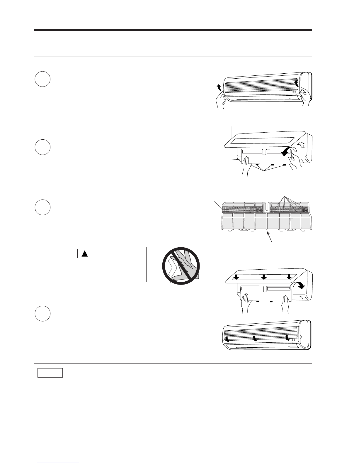
ATTACHING THE AIR CLEANSING AND DEODORIZING FILTERS
Before installation, be sure to stop the operation by using the remote controller.
1
Open the front panel.
● Pull up the front panel holding it at both sides by both
hands.
2
Remove the filter.
● Push the filter upward to release the claws
and pull out the filter.
3
Attaching the air cleansing and deodorizing filters to
the filter.
● Attach the air cleansing and deodorizing filters to the
frame by gently compress its both sides and release
after insertion into filter frame.
NOTE
● In case of removing the air cleansing and deodorizing filters, please follow the above procedures.
● The cooling capacity is slightly weakened and the cooling speed becomes slower when the air cleansing
and deodorizing filters are used. So, set the fan speed to "HIGH" when using it in this condition.
● Air cleansing and deodorizing filters are washable and reusable up to 20 times by using vacuum cleaner
or water rinse under running tap water. Type number for this air cleansing filter is <SPX-CFH5>.
● Do not operate the air conditioner without filter. Dust may enter the air conditioner and fault may occur.
4
Attach the filter.
● Attach the filter by ensuring that the surface written
“FRONT” is facing front.
● After attaching the filter, push the front panel at three
arrow portions as shown in figure and close it.
Claws (8 places)
Make sure the “FRONT” is facing back side
Claws
Front cover
Front panel
Air filter
!
CAUTION
Do not bend the air cleansing
and deodorizing filter as it may
cause damage to the structure.
Frame
– 25 –
INSTALLATION METHOD
REMOVING METHOD
Air filter
Air cleansing and
deodorizing filter
!
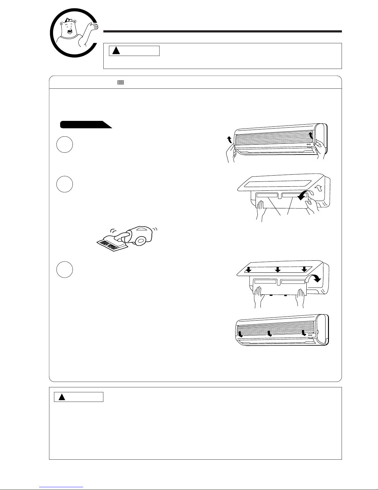
MAINTENANCE
Before the cleaning, stop operation and disconnect the power supply.
1. AIR FILTER
Clean the air filter, as it removes dust inside the room. In case the air filter is full of dust, the air flow
will decrease and the cooling capacity will be reduced. Further, noise may occur. Be sure to clean the
filter following the procedure below.
NOTE:
● Air cleansing and deodorizing filter should be cleaned every month or sooner if noticeable loading
occurs. When used overtime, it may loose its deodorizing function. For maximum performance,
it is recommended to replace it every 3-6 months depending on application requirements.
PROCEDURE
CAUTION
CAUTION
● Do not wash with hot water at more than 40°C. The filter may shrink.
● When washing it, shake off moisture completely and dry it in the shade; do not expose it directly
to the sun. The filter may shrink.
● Do not use detergent on the air cleansing and deodorizing filter as some detergent may deteriorate
the filter electrostatic performance.
Open the front panel and remove the filter
● Gently lift and remove the air cleansing and
deodorizing filters from the air filter frame.
1
● Re-insert the air cleansing and deodorizing
filters to the filter frame. Set the filter with
"FRONT" mark facing front, and slot them
into the original state.
● After attaching the filter, push the front panel
at three arrow portions as shown in figure
and close it.
3
● Vacuum dust from the air filter and air
cleansing and deodorizing filters using
vacuum cleaner. If there is too much dust,
rinse under running tap water and gently
brush it with soft bristle brush. Allow filters to
dry in shade.
2
!
– 26 –
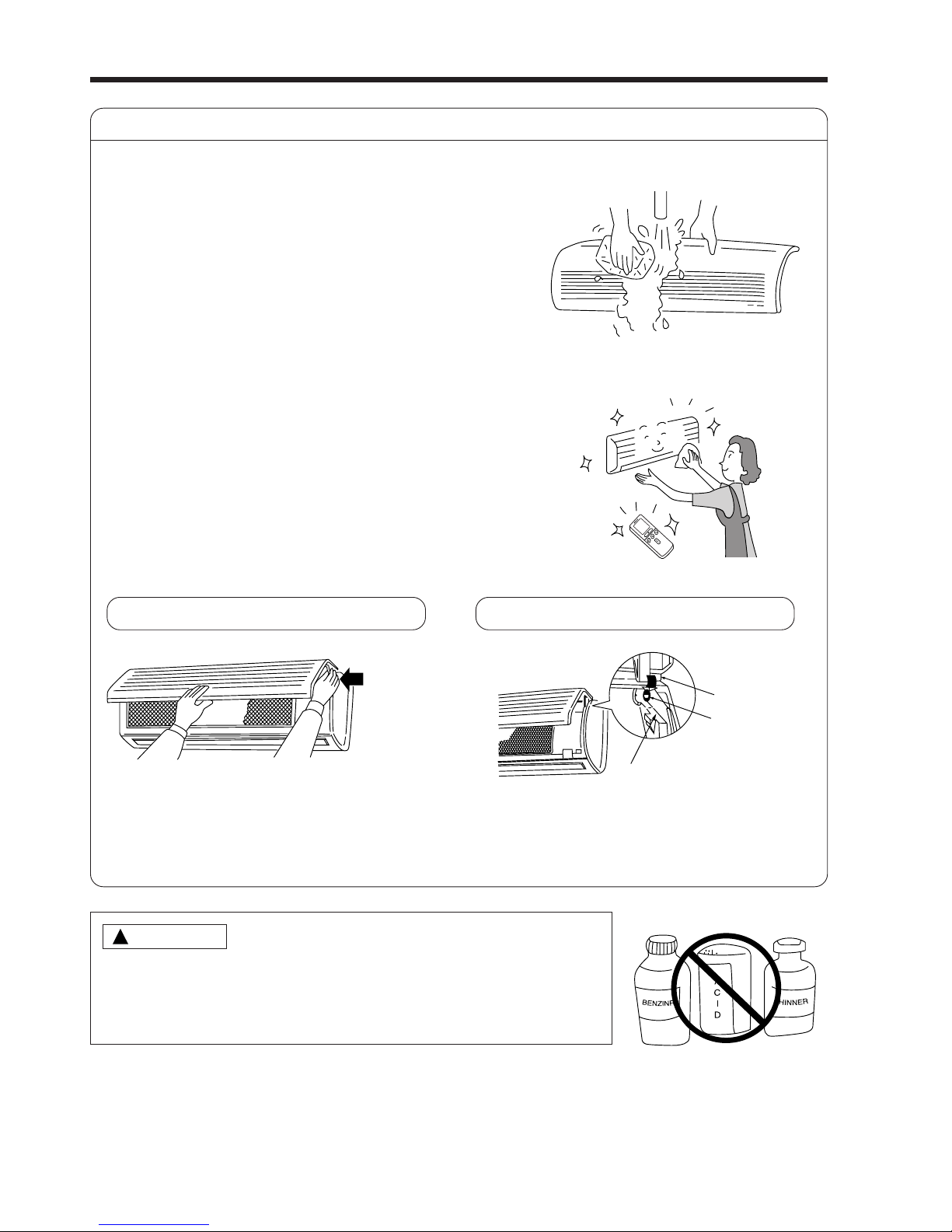
2. Washable Front Panel
● Remove the front panel and wash with clean
water.
Wash it with a soft sponge.
After using neutral detergent, wash thoroughly
with clean water.
● When front panel is not removed, wipe it with
a soft dry cloth. Wipe the remote controller
thoroughly with a soft dry cloth.
● Wipe the water thoroughly.
If water remains at indicators or signal
receiver of indoor unit, it causes trouble.
Method of removing the front panel.
Be sure to hold the front panel with both hands
to detach and attach it.
!
CAUTION
● Do not splash or direct water to the body of the unit when cleaning
it as this may cause short circuit.
● Never use hot water (above 40°C), benzine, gasoline, acid, thinner or
a brush, because they will damage the plastic surface and the coating.
Removing the Front Panel
Arm
● When the front panel is fully opened with
both hands, push the right arm to the inside
to release it, and while closing the front panel
slightly, put it out forward.
Attaching the Front Panel
● Move the projections of the left and right
arms into the Flanges in the unit and
securely insert them into the holes.
Projection
Hole
Flange
– 27 –
3. MAINTENANCE AT BEGINNING OF LONG OFF PERIOD
● Run the unit by setting the operation mode to
(COOL), the temperature to 32°C and the fan speed
to HI for about half a day on a fine day, and dry the
whole of the unit.
● Switch off the power plug.
1
2
3
REGULAR INSPECTION
PLEASE CHECK THE FOLLOWING POINTS BY QUALIFIED SERVICE PERSONAL EITHER
EVERY HALF YEARLY OR YEARLY. CONTACT YOUR SALES AGENT OR SERVICE SHOP.
Is the earth line disconnected or broken?
Is the mounting frame seriously affected by rust and is the
outdoor unit tilted or unstable?
Is the plug of power line firmly plugged into the socket?
(Please ensure no loose contact between them).
Air
Blow
Cleaning and maintenance must be carried out only by qualified service personal. Before cleaning,
stop operation and switch off the power supply.
!
CAUTION
Confirm
– 28 –
Please note:
On switching on the equipment, particularly when the room light is dimmed, a slight brightness fluctuation
may occur. This is of no consequence.
The conditions of the local Power Supply Companies are to be observed.
AFTER SALE SERVICE AND WARRANTY
WHEN ASKING FOR SERVICE, CHECK THE FOLLOWING POINTS.
When it does not operate
● Is the fuse all right?
● Is the voltage extremely high or low?
● Is the circuit breaker “ON”?
● Was the air filter cleaned?
● Does sunlight fall directly on the outdoor unit?
● Is the air flow of the outdoor unit obstructed?
● Are the doors or windows opened, or is there any source of
heat in the room?
● Is the set temperature suitable?
CONDITION CHECK THE FOLLOWING POINTS
Notes
● In quiet operation or stopping the operation, the following phenomena
may occassionally occur, but they are not abnormal for the operation.
(1) Slight flowing noise of refrigerant in the refrigerating cycle.
(2) Slight rubbing noise from the fan casing which is cooled and then
gradually warmed as operation stops.
● The odor will possibly be emitted from the room air conditioner because
the various odor, emitted by smoke, foodstuffs, cosmetics and so on,
sticks to it. So the air filter and the evaporator regularly must be cleaned
to reduce the odor.
●
Please contact your sales agent immediately if the air conditioner still fails to operate normally after the above
inspections. Inform your agent of the model of your unit, production number, date of installation. Please also
inform him regarding the fault.
●
Power supply shall be connected at the rated voltage, otherwise the unit will be broken or could not reach the
specified capacity.
When it does not cool well
When it does not hot well
 Loading...