

Hitachi RAS-18FH6, RAC-18YH6, RAC-25YH6, RAS-25FH6 Service Manual
AW
NO. 0024E
RAS-18FH6 RAC-18YH6
RAS-25FH6
RAC-25YH6
SERVICE MANUAL
TECHNICAL INFORMATION
FOR SERVICE PERSONNEL ONLY
RAS-18FH6
RAS-25FH6
RAC-18YH6
RAC-25YH6
REFER TO THE FOUNDATION MANUAL
CONTENTS
SPECIFICATIONS ------------------------------------------------------------------- 4
HOW TO USE ----------------------------------------------------------------------- 5
CONSTRUCTION AND DIMENSIONAL DIAGRAM --------------------- 15
MAIN PARTS COMPONENT --------------------------------------------------- 17
WIRING DIAGRAM ---------------------------------------------------------------- 19
CIRCUIT DIAGRAM --------------------------------------------------------------- 20
BLOCK DIAGRAM ----------------------------------------------------------------- 22
BASIC MODE ----------------------------------------------------------------------- 23
REFRIGERATING CYCLE DIAGRAM --------------------------------------
DESCRIPTION OF MAIN CIRCUIT OPERATION ----------------------- 30
SERVICE CALL Q & A ---------------------------------------------------------- 60
TROUBLE SHOOTING ----------------------------------------------------------- 63
Procedure for Disassembly and Reassembly 88
PARTS LIST AND DIAGRAM -------------------------------------------------- 90
--------------------------------------
- 29
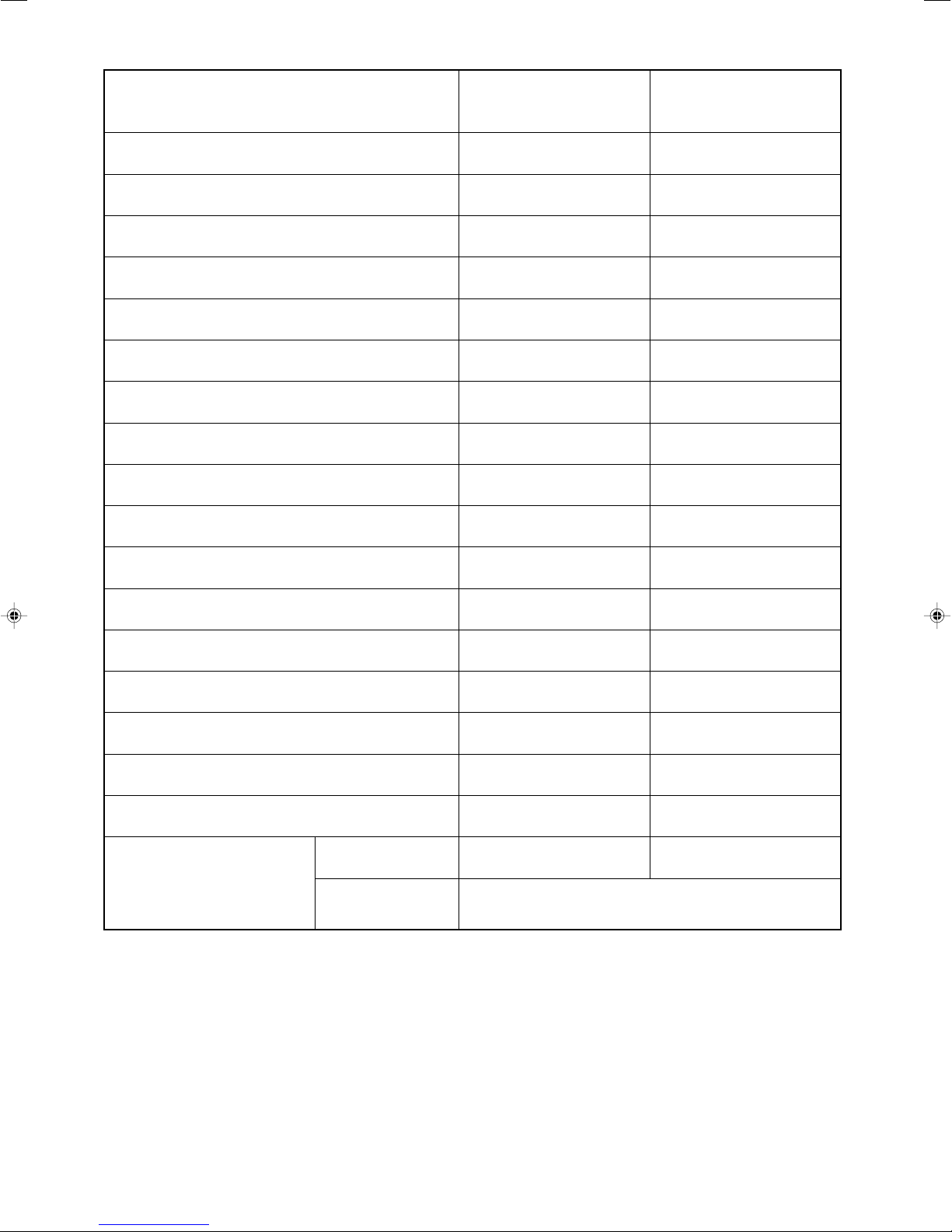
SPECIFICATIONS
TYPE
MODEL
POWER SOURCE
TOTAL INPUT
COOLING
HEATING
DIMENSIONS
(mm)
NET WEIGHT
TOTAL AMPERES
CAPACITY
TOTAL INPUT
TOTAL AMPERES
CAPACITY
(W)
(A)
(kW)
(B.T.U./h)
(W)
(A)
(kW)
(B.T.U./h)
W
H
D
(kg)
INDOOR UNIT
RAS-18FH6 RAC-18YH6
1 PHASE, 50 Hz, 220-230V
550 (155 ~ 1,010)
2.95-2.81
2.00 (0.90 ~ 2.50)
6,820 (3,070 ~ 8,530)
580 (115 ~ 970)
2.93-2.81
2.50 (0.90 ~ 3.20)
8,530 (3,070 ~ 10,920)
780
280
220
9.5
DC INVERTER (WALL TYPE)
OUTDOOR UNIT
700 (+68) 700 (+68)
505
258 (+48) 258 (+48)
27
INDOOR UNIT
RAS-25FH6 RAC-25YH6
1 PHASE, 50 Hz, 220-230V
700 (155 ~ 1,290)
3.75-3.59
2.50 (0.90 ~ 3.10)
8,530 (3,070 ~ 10,580)
880 (115 ~ 1,250)
4.45-4.26
3.40 (0.90 ~ 4.40)
11,600 (3,070 ~ 15,010)
780
280
220
9.5
OUTDOOR UNIT
After installation
505
27
SPECIFICATIONS AND PARTS ARE SUBJECT TO CHANGE FOR IMPROVEMENT
ROOM AIR CONDITIONER
FEBRUARY 2008 Hitachi Household Appliances(Wuhu) Co.,Ltd.
INDOOR UNIT + OUTDOOR UNIT
SAFETY DURING REPAIR WORK
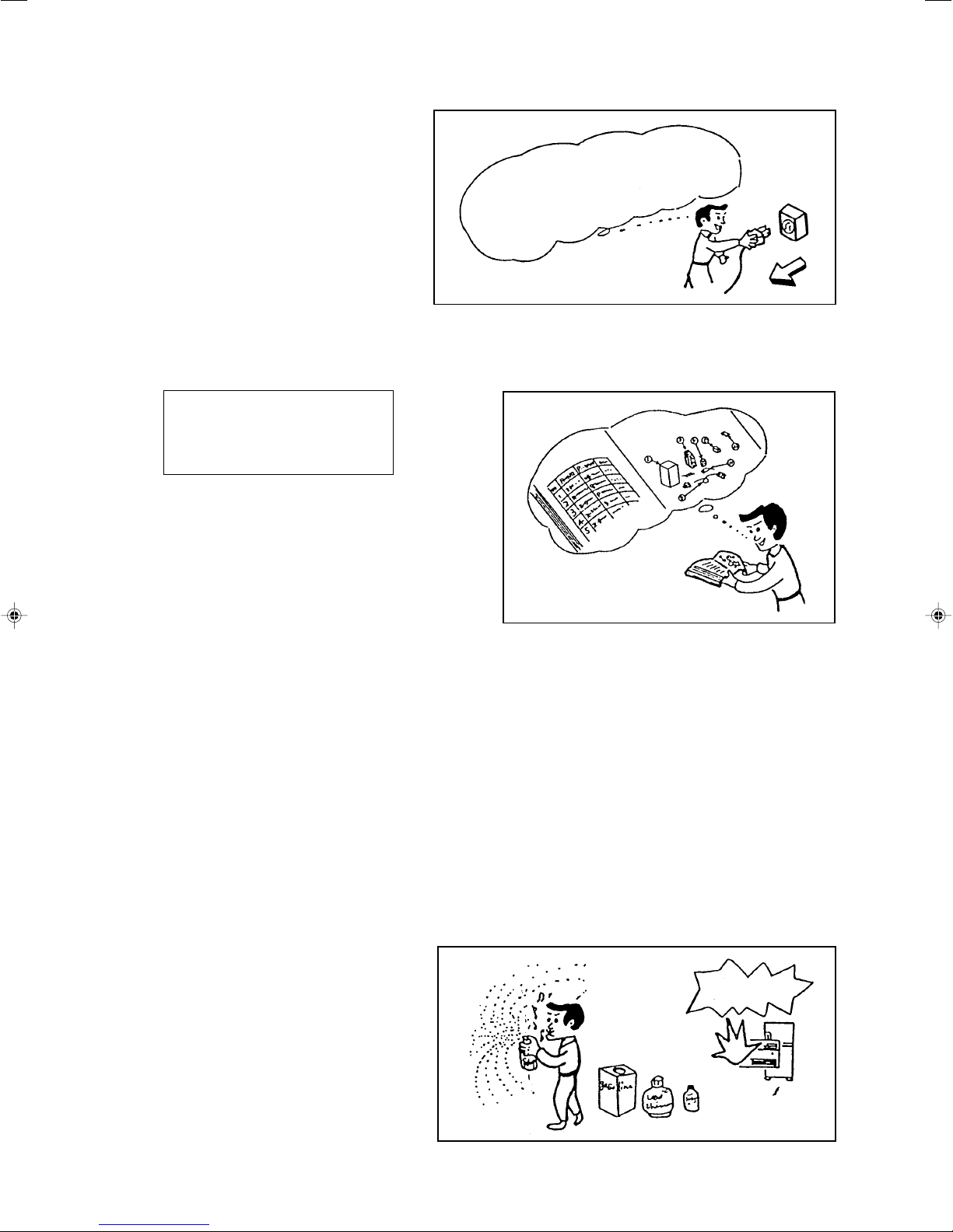
1. In order to disassemble and repair the unit
in question, be sure to disconnect the power
cord plug from the power outlet before
starting the work.
First, I must disconnect
the power cord plug
from the power outlet.
2. If it is necessary to replace any parts, they should be replaced with respective genuine parts for the unit, and
the replacement must be effected in correct manner according to the instructions in the Service Manual of the
unit.
If the contacts of electrical
parts are defective, replace the
electrical parts without trying to
repair them.
3. After completion of repairs, the initial state should
be restored.
4. Lead wires should be connected and laid as in the
initial state.
5. Modification of the unit by user himself should
absolutely be prohibited.
6. Tools and measuring instruments for use in repairs or inspection should be accurately calibrated in advance.
7. In installing the unit having been repaired, be careful to prevent the occurence of any accident such as
electrical shock, leak of current, or bodily injury due to the drop of any part.
8. To check the insulation of the unit, measure the insulation resistance between the power cord plug and grounding
terminal of the unit. The insulation resistance should be 1MΩ or more as measured by a 500V DC megger.
9. The initial location of installation such as window, floor or the other should be checked for being and safe
enough to support the repaired unit again.
If it is found not so strong and safe, the unit should be installed at the initial location reinforced or at a new
location.
10. Any inflammable thing should never be placed about the location of installation.
11. Check the grounding to see whether it is
proper or not, and if it is found improper,
connect the grounding terminal to the earth.
DANGER
WORKING STANDARDS FOR PREVENTING BREAKAGE OF SEMICONDUCTORS
1. Scope
The standards provide for items to be generally observed in carrying and handling semiconductors in relative
manufacturers during maintenance and handling thereof. (They apply the same to handling of abnormal
goods such as rejected goods being returned).
2. Object parts
(1) Micro computer
(2) Integrated circuits (IC)
(3) Field-effect transistors (FET)
(4) P.C. boards or the like on which the parts mentioned in (1) and (2) of this paragraph are equipped.
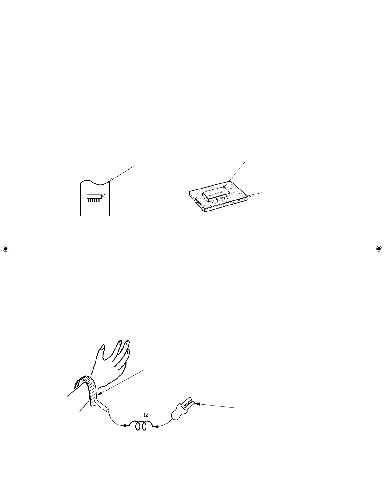
3. Items to be observed in handling
(1) Use a conductive container for carrying and storing of parts. (Even rejected goods should be handled in
the same way).
A conductive polyvinyl bag
IC
Conductive sponge
IC
Fig. 1 Conductive Container
(2) When any part is handled uncovered (in counting, packing and the like), the handling person must always
use himself as a body earth. (Make yourself a body earth by passing one M ohm earth resistance through
a ring or bracelet).
(3) Be careful not to touch the parts with your clothing when you hold a part even if a body earth is being
taken.
(4) Be sure to place a part on a metal plate with grounding.
(5) Be careful not to fail to turn off power when you repair the printed circuit board. At the same time, try to
repair the printed circuit board on a grounded metal plate.
Body earth
(Elimik conductive band)
1M
Clip for connection with a
grounding wire
Fig. 2 Body Earth
– 1 –
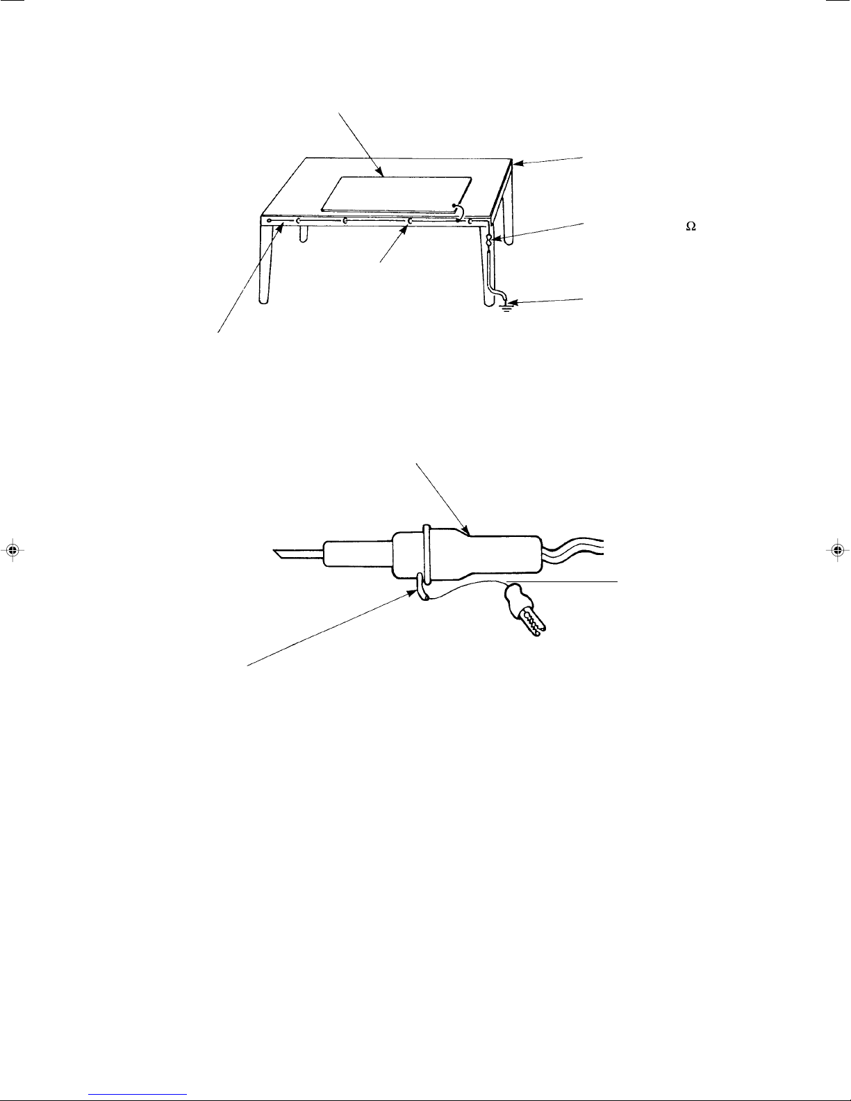
(6)Use a three wire type soldering iron including a grounding wire.
Metal plate (of aluminium, stainless steel, etc.)
Working
table
Bare copper wire (for body earth)
Staple
Fig. 3 Grounding of the working table
Soldering iron
Resistor of 1 M
Earth wire
Grounding
wire
(1/2W)
Screw stop at the screwed
part using a rag plate
Fig. 4 Grounding a soldering iron
Use a high insulation mode (100V, 10M or higher) when ordinary iron is to be used.
(7) In checking circuits for maintenance, inspection or some others, be careful not to have the test probes of
the measuring instrument shortcircuit a load circuit or the like.
– 2 –

CAUTION
!
1. In quiet operation or stopping the running, slight flowing noise of refrigerant in the refrigerating cycle is
heard occasionally, but this noise is not abnormal for the operation.
2. When it thunders near by, it is recommend to stop the operation and to disconnect the power cord plug from
the power outlet for safety.
3. The room air conditioner does not start automatically after recovery of the electric power failure for prevent-
ing fuse blowing. Re-press START/STOP button after 3 minutes from when unit stopped.
4. If the room air conditioner is stopped by adjusting thermostat, or missoperation, and re-start in a moment,
there is occasion that the cooling and heating operation does not start for 3 minutes, it is not abnormal and
this is the result of the operation of IC delay circuit. This IC delay circuit ensures that there is no danger of
blowing fuse or damaging parts even if operation is restarted accidentally.
5. This room air conditioner should not be used at the cooling operation when the outside temperature is
below -10°C (14°F).
6. This room air conditioner (the reverse cycle) should not be used when the outside temperature is below
–15°C (5°F).
If the reverse cycle is used under this condition, the outside heat exchanger is frosted and efficiency falls.
7. When the outside heat exchanger is frosted, the frost is melted by operating the hot gas system, it is not
trouble that at this time fan stops and the vapour may rise from the outside heat exchanger.
– 3 –
SPECIFICATIONS
MODEL
FAN MOTOR
FAN MOTOR CAPACITOR
FAN MOTOR PROTECTOR
COMPRESSOR
COMPRESSOR MOTOR CAPACITOR
OVERLOAD PROTECTOR
OVERHEAT PROTECTOR
FUSE (for MICROPROCESSOR)
POWER RELAY
POWER SWITCH
RAS-18FH6
RAS-25FH6
PWM DC35V
NO
NO
–
NO
NO
NO
NO
NO
YES
RAC-18YH6
RAC-25YH6
40 W
NO
NO
ASC092CD
NO
YES
YES
3.0A
G4A
NO
TEMPORARY SWITCH
SERVICE SWITCH
TRANSFORMER
VARISTOR
NOISE SUPPRESSOR
THERMOSTAT
REMOTE CONTROL SWITCH (LIQUID CRYSTAL)
REFRIGERANT CHARGING
UNIT
VOLUME
(Refrigerant 410A)
PIPES (MAX. 20m)
YES
NO
NO
NO
NO
YES(IC)
YES
----------
NO
YES
NO
450NR
YES
YES(IC)
NO
820g
WITHOUT REFRIGERANT BECAUSE
COUPLING IS FLARE TYPE.
– 4 –
– 2 –
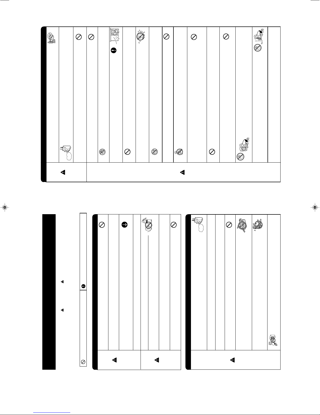
SAFETY PRECAUTION
• Please read the “Safety Precaution” carefully before operating the unit to ensure correct usage of the unit.
• Pay special attention to signs of “
Warning” and “ Caution”. The “Warning” section contains
matters which, if not observed strictly, may cause death or serious injury. The “Caution” section
contains matters which may result in serious consequences if not observed properly. Please observe
all instructions strictly to ensure safety.
• The signs indicate the following meanings. (The following are examples of signs.)
• Please keep this manual after reading.
This sign in the figure indicates prohibition. Indicates the instructions that must be followed.
WARNING
CAUTION
• Do not reconstruct the unit.
Water leakage, fault, short circuit or fire may occur if you reconstruct the unit by
yourself.
• Please ask your sales agent or qualified technician for the installation of your
unit.
Water leakage, short circuit or fire may occur if you install the unit by yourself.
• Please use earth line.
Do not place the earth line near water or gas pipes, lightning-conductor, or the
earth line of telephone. Improper installation of earth line may cause electric
shock.
• Be sure to use the specified piping set for R410A. Otherwise, this may result in
broken copper pipes or faults.
• A circuit breaker should be installed depending on the mounting site of the unit.
Without a circuit breaker, the danger of electric shock exists.
• Do not install the unit near a location where there is flammable gas.
The outdoor unit may catch fire if flammable gas leaks around it. Piping shall be
suitable supported with a maximum spacing of 1m between the supports.
• Please ensure smooth flow of water when installing the drain hose. If any failure
is found in the drain path, water drops from the indoor and outdoor units, causing
wet household effects.
• Make sure that a single phase 230V power source is used.
The use of other power sources may cause electrical components to overheat
and lead to fire.
PROHIBITION
CONNECT EARTH LINE
PROHIBITION
PROHIBITION
• Should abnormal situation arise (like burning smell), please stop operating the
unit and remove plug from the socket or turn off the circuit breaker. Contact your
agent. Fault, short circuit or fire may occur if you continue to operate the unit
under abnormal situation.
• Please contact your agent for maintenance.
Improper self maintenance may cause electric shock and fire.
• Please contact your agent if you need to remove and reinstall the unit.
Electric shock or fire may occur if you remove and reinstall the unit yourself improperly.
WARNING
PRECAUTIONS DURING INSTALLATION
PRECAUTIONS DURING SHIFTING OR MAINTENANCE
“OFF”
PROHIBITION
• Avoid an extended period of direct air flow for your health.
• Do not connect the power calbe with an extension cable or do not plug too many
leads of the other electric appliance into the socket where this cable is plugged.
In addition, wire the cable with some allowances to prevent the cable from stretching.
Not doing so will cause an electrical shock, heat generation or fire.
PROHIBITION
• Do not put objects like thin rods into the panel of blower and suction side
because the high-speed fan inside may cause danger.
• Do not bundle the power cable, pull it, put something on it, heat it, process it, or
put it between things. Breakage of the power cable may result.
Use of a damaged cable may cause an electrical shock or a fire.
PROHIBITION
PROHIBITION
HOW TO USE
– 3 –
WARNING
PRECAUTIONS DURING OPERATION
• Do not use any conductor as fuse wire, this could cause fatal accident.
PROHIBITION
• During thunder storm, disconnect the plug top or turn off the circuit breaker.
• Spray cans and other combustibles should not be located within a meter of the air
outlets of both indoor and outdoor units.
As a spray can’s internal pressure can be increased by hot air, a rupture may result.
“OFF”
CAUTION
PROHIBITION
• The product shall be operated under the manufacturer specification and not for
any other intended use.
PROHIBITION
DON’T WET
• Do not attempt to operate the unit with wet hands, this could cause fatal accident.
STRICTLY OBSERVE
PRECAUTIONS
PROHIBITION
PROHIBITION
PROHIBITION
PROHIBITION
PROHIBITION
• When operating the unit with burning equipments, regularly ventilate
the room to avoid oxygen insufficiency.
• Do not direct the cool air coming out from the air-conditioner panel to
face household heating apparatus as this may affect the working of
apparatus such as the electric kettle, oven etc.
• Do not wash the unit with water or place a water container such as a
vase on the indoor unit.
Electrical leakage could be present and cause electric shock.
• Please ensure that outdoor mounting frame is always stable, firm and
without defect. If not, the outdoor unit may collapse and cause danger.
• Do not place plants or animals directly under the air flow as it is bad for the plants or
animals.
• Do not climb on the outdoor unit or put objects on it.
PROHIBITION
PROHIBITION
PROHIBITION
DON’T TOUCH
DON’T TOUCH
• When operating the unit with the door and windows opened, (the room humidity
is always above 80%) and with the air deflector facing down or moving automati-
cally for a long period of time, water will condense on the air deflector and drips
down occasionally. This will wet your furniture. Therefore, do not operate under
such condition for a long time.
• If the amount of heat in the room is above the cooling or heating capability of the
unit (for example: more people entering the room, using heating equipments and
etc.), the preset room temperature cannot be achieved.
• This appliance especially indoor unit cleaning must be performed by authorized
personnel only. Consult your sales agent.
Using a commercially available detergent or similar can damage the plastic parts
or clog the drain pipe, causing water to drip with potential electric shock hazard.
• Do not touch the air outlet, bottom surface and aluminum fin of the outdoor
unit.
You may get hurt.
• Do not touch the refrigerant pipe and connecting valve.
Burns may result.
• This appliance is not intended for use by young children or infirm persons unless they have been
adequately supervised by a responsible person to ensure that they can use this appliance safely.
• Young children should be supervised to ensure that they do not play with the appliance.
– 5 –
– 4 –
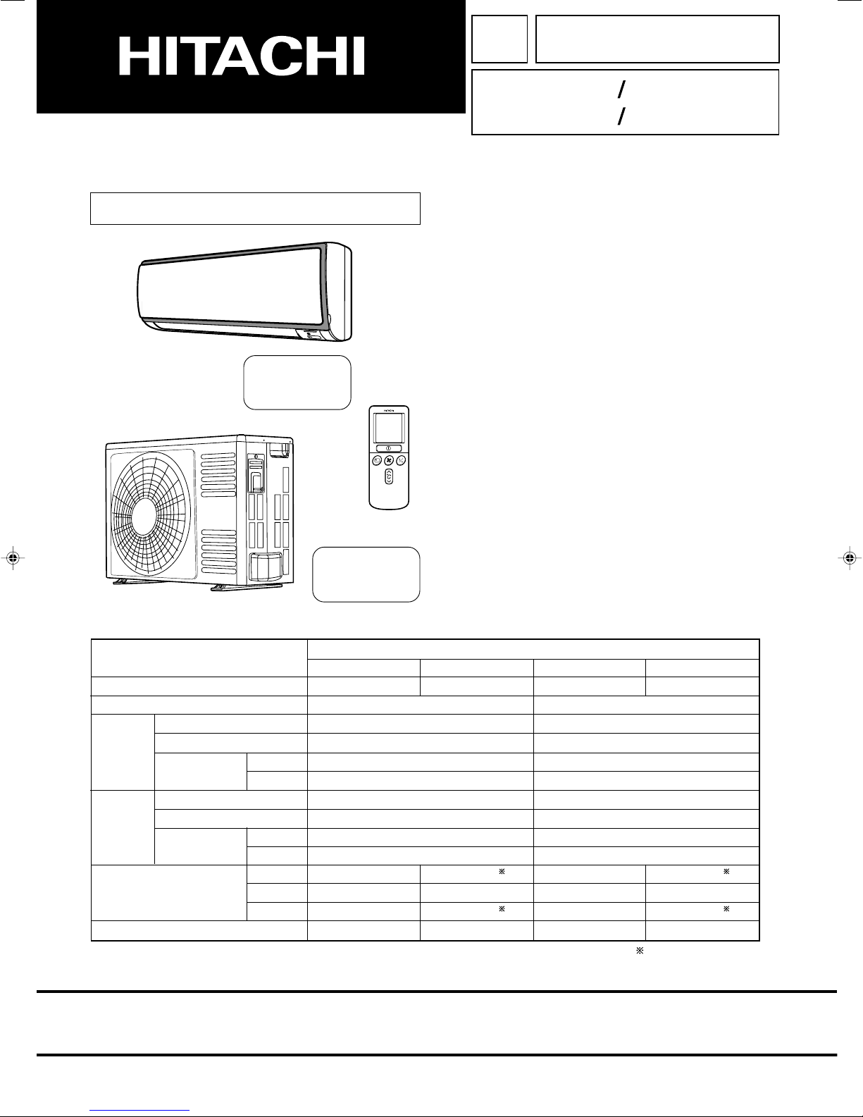
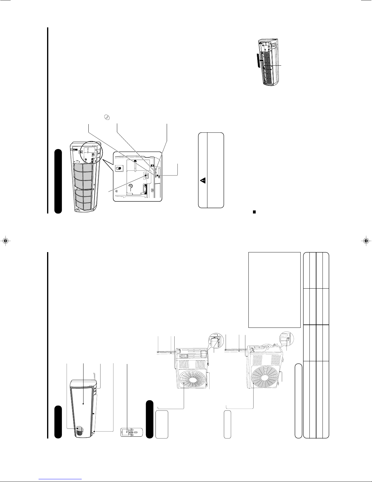
NAMES AND FUNCTIONS OF EACH PART
INDOOR UNIT
Air filter
To prevent dust from coming into the indoor unit.
(Refer page 16)
Front panel
Indoor unit indicators
Light indicator showing the operating condition.
(Refer page 5)
Horizontal deflector Vertical deflector
(Air Outlet)
(Refer page 15)
Remote controller
Send out operation signal to the indoor unit. So as
to operate the whole unit.
(Refer page 6)
MODEL NAME AND DIMENSIONS
About the outdoor unit:
• When “Stop” is selected during operation
of the indoor unit, the fan of the outdoor
unit continues turning for 10 to 60
seconds to cool the electric parts down.
• In heating operation, condensate or
water due to defrosting will flow.
Do not cover the drain port of the outdoor
unit because such water may freeze in
the chilly area.
• When the outdoor unit is hung on the
ceiling, install the bush and drain pipe
on the drain port and drain water.
MODEL WIDTH (mm) HEIGHT (mm) DEPTH (mm)
RAS-18FH6, RAS-25FH6, RAS-35FH6 780 280 220
RAC-18YH6, RAC-25YH6 700 505 258
RAC-35YH6 750 548 288
Air outlet
When “ heating” operation is
performed, cool air blows and
when “cooling” or “dehumidifying”
operation is performed, warm air
blows.
Drain hose
Drains the dehumidified water from the indoor unit to the
outdoor during “cooling” or “dehumidifying” operation.
Piping and Wiring
Air inlets (Rear and left sides)
Drain port
(Bottom)
Earth terminal
(Lower section of the side)
RAC-35YH6
RAC-18YH6
RAC-25YH6
OUTDOOR UNIT
– 5 –
NAMES AND FUNCTIONS OF EACH PART
INDOOR UNIT INDICATIONS
TIMER LAMP (Orange)
This lamp lights when the timer is working.
FILTER LAMP (Green)
When the device is operated for a total of about 200
hours, the FILTER lamp lights indicates that it is time
to clean the filter.The lamp goes out when the
“
(AUTO SWING)” button is pressed while the
operation is stopped.
OPERATION LAMP (Yellow)
This lamp lights during operation.
The OPERATION LAMP flashes in the following
cases during heating.
(1) During preheating
For about 2-3 minutes after starting up.
(2) During defrosting
Defrosting will be performed about once an hour
when frost forms on the heat exchanger of the
outdoor unit, for 5-10 minutes each time.
TEMPORARY SWITCH
●
Use this switch to start and stop when the remote controller does not work.●This temporary operation will be at the most recent setting made. (The unit
will immediately go into automatic operation once power is switched on.)
CAUTION
Turn off the circuit breaker or pull out
the power plug if the unit is not be
operated for a long period.
✩ If the power stays on and the unit is not operated, power is slightly consumed in the control circuit.
The power is saved by turning off the power switch (or the circuit breaker when the power is supplied
from the outdoor unit).
Attaching the air cleansing and deodorizing filters (Accessories) to the filter frame.
• Attach the air cleansing and deodorizing filters to the frame by
gently compress its both sides and release after insertion into
filter frame.
• The cooling capacity is slightly weakened and the cooling speed
becomes slower when the air cleansing and deodorizing filters
are used.
• Air cleansing and deodorizing filters are washable and reusable up to 20 times by using vacuum
cleaner or water rinse under running tap water. When you want to renew it, please ask your sales
agent. Optional air cleansing and deodorizing filters(SPX-CFH11).
Frame
POWER SWITCH
– 6 –
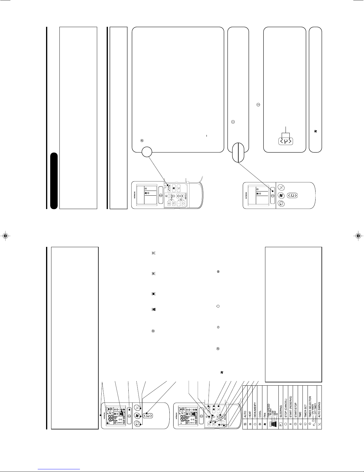
– 6 –
● Signal emitting window/transmission sign
Point this window toward the indoor unit when controlling it.
The transmission sign blinks when a signal is sent.
● Display
This indicates the room temperature selected, current time, timer status,
function and intensity of circulation selected.
● START/STOP button
Press this button to start operation. Press it again to stop operation.
● AUTO SWING button
Controls the angle of the horizontal air deflector.
● FAN SPEED selector
This determines the fan speed. Every time you press this button, the intensity of
circulation will change from (AUTO) to (HI) to (MED) to (LOW) to
(SILENT). (This button allows selecting the optimal or preferred fan speed for
each operation mode.)
● SLEEP button
Use this button to set the sleep timer.
● TEMPERATURE buttons
Use these buttons to raise or lower the temperature setting. (Keep pressed, and
the value will change more quickly.)
● TIME button
Use this button to set and check the time and date.
● RESET button
Press this button after the batteries are replaced or when some irregular
operation is found.
● FUNCTION selector
Use this button to select the operating mode. Every time you press it, the mode
will change from (AUTO) to (HEAT) to (DEHUMIDIFY) to (COOL) and
to (FAN) cyclically.
● FAN SPEED selector
● AUTO SWING button
● TIMER control
Use these buttons to set the timer.
● OFF-TIMER button Select the turn OFF time.
● ON-TIMER button Select the turn ON time.
● RESERVE button Time setting reservation.
● CANCEL button Cancel time reservation.
NAMES AND FUNCTIONS OF EACH PART
REMOTE CONTROLLER
• This controls the operation of the indoor unit.
The range of control is about 7 meters. If indoor lighting is controlled electronically, the range of
control may be shorter, in some cases, the control signal may not be received.
This unit can be fixed on a wall using the fixture provided. Before fixing it, make sure the indoor unit
can be controlled from the remote controller.
• Handle the remote controller with care.
Dropping it or getting it wet may compromise its signal transmission capability.
• After new batteries are inserted into the remote controller, the unit will initially require approximately
10 seconds to respond to commands and operate.
Precautions for Use
• Do not put the remote controller in the following places.
• In direct sunlight
• In the vicinity of a heater.
• Handle the remote controller carefully. Do not drop it on the floor, and
protect it from water.
• Once the outdoor unit stops, it will not restart for about 3 minutes (unless
you turn the power switch off and on or unplug the power cord and plug
it in again).
This is to protect the device and does not indicate a failure.
• If you press the FUNCTION selector button during operation, the device
may stop for about 3 minutes for protection.
– 7 –
VARIOUS FUNCTIONS
■ Auto Restart Control
• If there is a power failure, operation will be automatically restarted when the power is resumed with
previous operation mode and airflow direction.
(As the operation is not stopped by remote controller.)
• If you intend not to continue the operation when the power is resumed, switch off the power supply.
When you switch on the circuit breaker, the operation will be automatically restarted with previous
operation mode and airflow direction.
Note: 1. If you do not require Auto Restart Control, please consult your sales agent.
2. Auto Restart Control is not available when Timer or Sleep Timer mode is set.
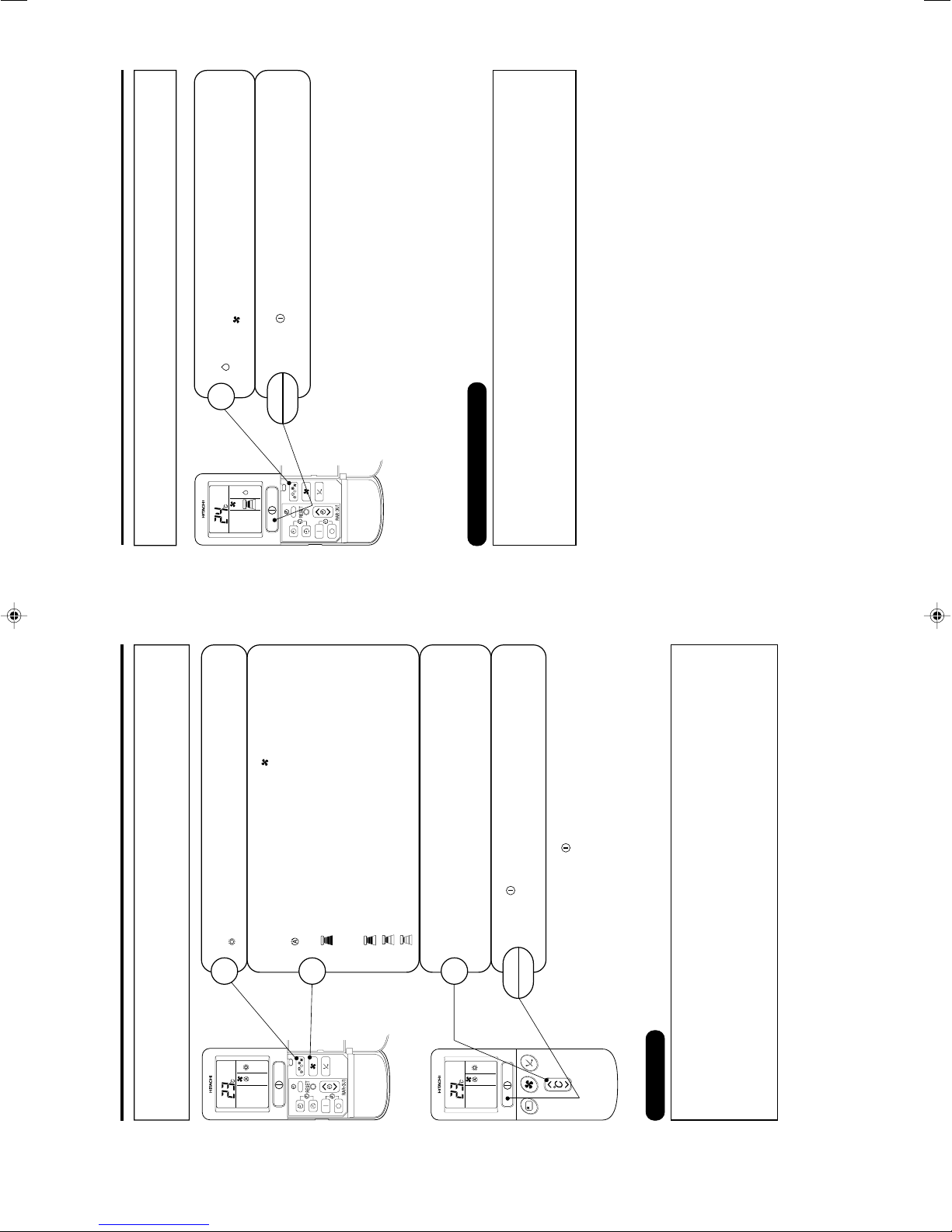
AUTOMATIC OPERATION
The device will automatically determine the mode of operation, HEAT or COOL depending on the
initial room temperature. The selected mode of operation will change when the room temperature
varies.
Press the FUNCTION selector so that the display indicates the
(AUTO) mode of operation.
• When AUTO has been selected, the device will automatically
determine the mode of operation, HEAT or COOL depending
on the current room temperature.
• When AUTO is first selected, the device will determine the
current room temperature and select the proper operation
mode accordingly.
• When the air conditioner has adjusted the room's temperature
to the near preset temperature, it will begin to monitor
operation. If the room temperature subsequently changes,
the air conditioner will once again select the appropriate
operation (heating or cooling) to adjust the temperature to
the preset temperature. The monitoring operation range is
+
3°C relative to the preset temperature.
• If the mode automatically selected by the unit is not
satisfactory, manually change the mode setting (heat,
dehumidify, cool or fan).
1
Press the
(START/STOP) button.
Operation starts with a beep.
Press the button again to stop operation.
Press the (FAN SPEED) button to select AUTO, LOW and SILENT.
■ As the settings are stored in memory in the remote controller, you
only have to press the
(START/STOP) button next time.
You can raise or lower the temperature setting as necessary by
maximum of 3°C.
Press the temperature button and the temperature
setting will change by 1°C each time.
• The preset temperature and the actual room temperature may
vary somewhat depending on conditions.
START
STOP
– 7 –
– 8 –
Press the (START/STOP) button. Heating operation starts
with a beep. Press the button again to stop operation.
START
STOP
HEATING OPERATION
• Use the device for heating when the outdoor temperature is under 21°C.
When it is too warm (over 21°C), the heating function may not work in order to protect the device.
• In order to keep reliability of the device, please use this device above -15°C of the outdoor
temperature.
Press the FUNCTION selector so that the display indicates
(HEAT).
1
Set the desired FAN SPEED with the (FAN SPEED) button
(the display indicates the setting).
(AUTO) : The fan speed changes automatically according
to the temperature of the air which blows out.
(HI) : Economical as the room will become warm
quickly.
But you may feel a chill at the beginning.
(MED) : Quiet.
(LOW) : More quiet.
(SILENT): Silent.
2
Set the desired room temperature with the TEMPERATURE
buttons (the display indicates the setting).
The temperature setting and the actual room temperature may
vary somewhat depending on conditions.
3
■ As the settings are stored in memory in the remote controller, you
only have to press the
(START/STOP) button next time.
■ Defrosting
Defrosting will be performed about once an hour when frost forms on the heat exchange of the outdoor unit,
for 5~10 minutes each time.
During defrosting operation, the operation lamp blinks in cycle of 3 seconds on and 0.5 second off.
The maximum time for defrosting is 20 minutes.
(If the piping length used is longer than usual, frost will likely to form.)
– 9 –
DEHUMIDIFYING OPERATION
Use the device for dehumidifying when the room temperature is over 16°C.
When it is under 15°C, the dehumidifying function will not work.
Press the
(START/STOP) button.
START
STOP
Press the FUNCTION selector so that the display indicates
(DEHUMIDIFY).
Press the
(FAN SPEED) button to select LOW and SILENT.
1
■ When you want to change the operation mode, please use the
FUNCTION selector.
■ Set the desired temperature is available.
■ You also can use the FUNCTION selector to select this operation.
■ Dehumidifying Function
• Dehumidifying takes place with a target temperature which is slightly lower than the room
temperature setting. (However, target temperature is 16°C for a temperature setting of 16°C.)
If the room temperature becomes lower than the target value, operation stops. If the room
temperature becomes higher than the target value, operation restarts.
• The preset room temperature may not be reached depending on the number of people present in
the room conditions.
– 8 –
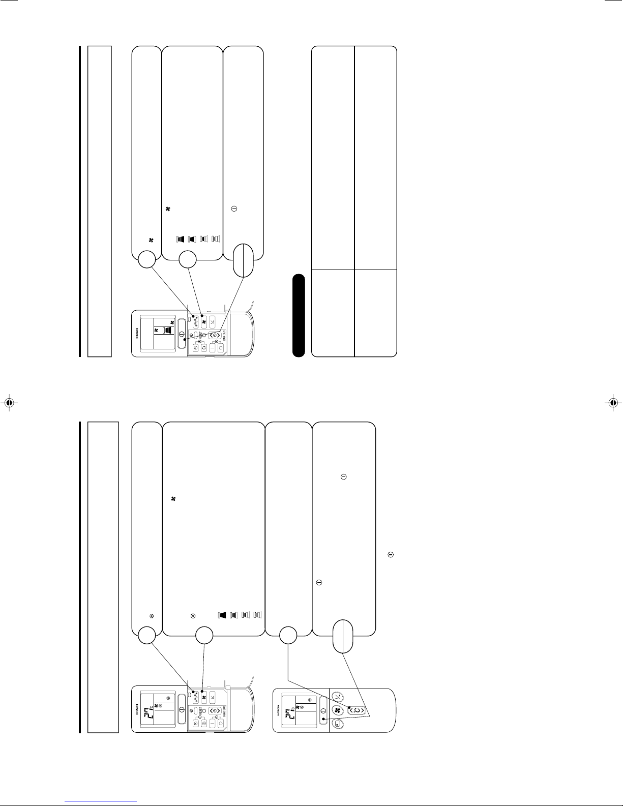
– 10 –
Press the (START/STOP) button. Cooling operation starts
with a beep. Press the button again to stop operation. The cooling
function does not start if the temperature setting is higher than
the current room temperature (even though the (OPERATION)
lamp lights).
The cooling function will start as soon as you set the temperature
below the current room temperature.
START
STOP
COOLING OPERATION
Use the device for cooling when the outdoor temperature is -10 to 42°C.
If humidity is very high (over 80%) indoors, some dew may form on the air outlet grille of the indoor
unit.
Press the FUNCTION selector so that the display indicates
(COOL).
1
Set the desired FAN SPEED with the (FAN SPEED) button
(the display indicates the setting).
(AUTO) : The FAN SPEED is HI at first and varies to MED
automatically when the preset temperature has
been reached.
(HI) : Economical as the room will become cool quickly.
(MED) : Quiet.
(LOW) : More quiet.
(SILENT): Silent.
2
Set the desired room temperature with the TEMPERATURE
buttons (the display indicates the setting).
The temperature setting and the actual room temperature may
vary somewhat depending on conditions.
3
■ As the settings are stored in memory in the remote controller, you
only have to press the
(START/STOP) button next time.
– 11 –
Press the
(START/STOP) button. Fan operation starts with a
beep.
Press the button again to stop operation.
START
STOP
FAN OPERATION
You can use the device simply as an air circulator. Use this function to dr y the interior of the indoor unit
at the end of summer.
Press the FUNCTION selector so that the display indicates
(FAN).
1
Press the (FAN SPEED) button.
(HI) : The strongest air blow.
(MED) : Quiet.
(LOW) : More quiet.
(SILENT): Silent.
2
FAN SPEED (AUTO)
… When the AUTO fan speed mode is set in the cooling/heating operation:
For the heating operation
• The fan speed will automatically change according to the temperature of
discharged air.
• As room temperature reaches the preset temperature, a very light breeze
will blow.
• Operation starts in the “HI” mode to reach the preset temperature.
• As room temperature approaches the preset temperature, fan speed auto-
matically switches to “LOW”.
For the cooling operation
– 9 –
– 12 –
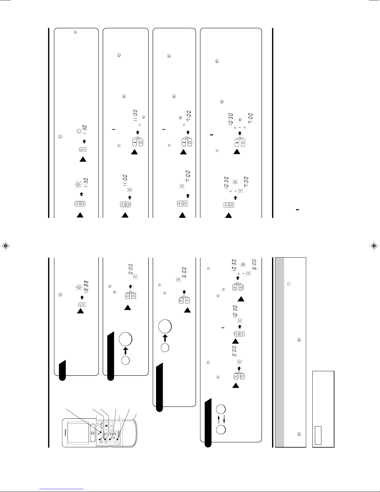
HOW TO SET THE TIMER
Time
TIME
(current time)
OFF TIMER
ON TIMER
RESERVE
CANCEL
OFF-Timer
ON-Timer
ON/OFF-Timer
After you change the
batteries;
Start
Stop
You can set the device to turn off at
the present time.
1
Press the (OFF-TIMER)
button. The (OFF) mark blinks
on the display.
The device will turn on at the
designated times.
1
Press the (ON-TIMER)
button. The (ON) mark blinks on
the display.
AM
Start Stop
• The device will turn on (off) and
off (on) at the designated times.
• The switching occurs first at the
preset time that comes earlier.
• The arrow mark appearing on the
display indicates the sequence of
switching operations.
1
Press the (OFF-
TIMER) button so that
the (OFF) mark
blinks.
2
Set the turn-off time
with the TIMER control
button.
Press the (RESERVE)
button.
PM
3
Press the (ON-
TIMER) button so that the
(OFF) mark lights and
the (ON) mark blinks.
PM
AM
How to Cancel Reservation
Point the signal window of the remote controller toward the indoor unit, and press the (CANCEL)
button.
The
(RESERVED) sign goes out with a beep and the (TIMER) lamp turns off on the indoor unit.
NOTE
You can set only one of the OFF-timer,
ON-timer and ON/OFF-timer.
Start
Stop
AM
PM
1
Set the (TIME) button.
AM
PM
– 13 –
ENGLISH
• The time indication will disappear automatically in
10 seconds.
• To check the current time setting, press the
(TIME) button twice.
The setting of the current time is now complete.
2
Set the turn-off time with
the TIMER control button.
PM
3
Point the signal window of the remote controller toward the indoor unit,
and press the (RESERVE) button.
The (OFF) mark starts lighting instead of flashing and the
(RESERVED)
sign lights. A beep occurs and the
(TIMER) lamp lights on the indoor unit.
PM
Example: The device will turn off at 11:00p.m.
The setting of turn-off time is now complete.
2
Set the turn-on time with
the TIMER control button.
AM
3
Point the signal window of the remote controller toward the indoor unit,
and press the (RESERVE) button.
The (ON) mark starts lighting instead of flashing and the
(RESERVED)
sign lights. A beep occurs and the
(TIMER) lamp lights on the indoor unit.
AM
Example:
The device will turn on early so that the preset
temperature be almost reached at 7:00 a.m.
The setting of the turn-on time is now complete.
4
Set the turn-on time with
the TIMER control button.
5
Point the signal window of the remote controller toward the indoor unit,
and press the (RESERVE) button.
The (ON) mark starts lighting instead of flashing and the (RESERVED)
sign lights. A beep occurs and the
(TIMER) lamp lights on the indoor unit.
Example:
For heating, the device will turn off at 10:30 p.m.,
and then turn on early so that the preset
temperature be almost reached at 7:00 a.m.;
for cooling and dehumidifying, it will simply
turned on at 7:00 a.m. The settings of the turn
on/off times are now complete.
PM
AM
PM
AM
• The timer may be used in three ways: off-timer, on-timer and ON/OFF (OFF/ON)-timer. Set the
current time at first because it serves as a reference.
• As the time settings are stored in memory in the remote controller, you only have to press the
(RESERVE) button is order to use the same settings next time.
2
Set the current time with
the TIMER control button.
PM
Example: The current time is 1:30p.m.
3
Press the (TIME) button
again. The time indication starts
lighting instead of flashing.
PM
– 10 –
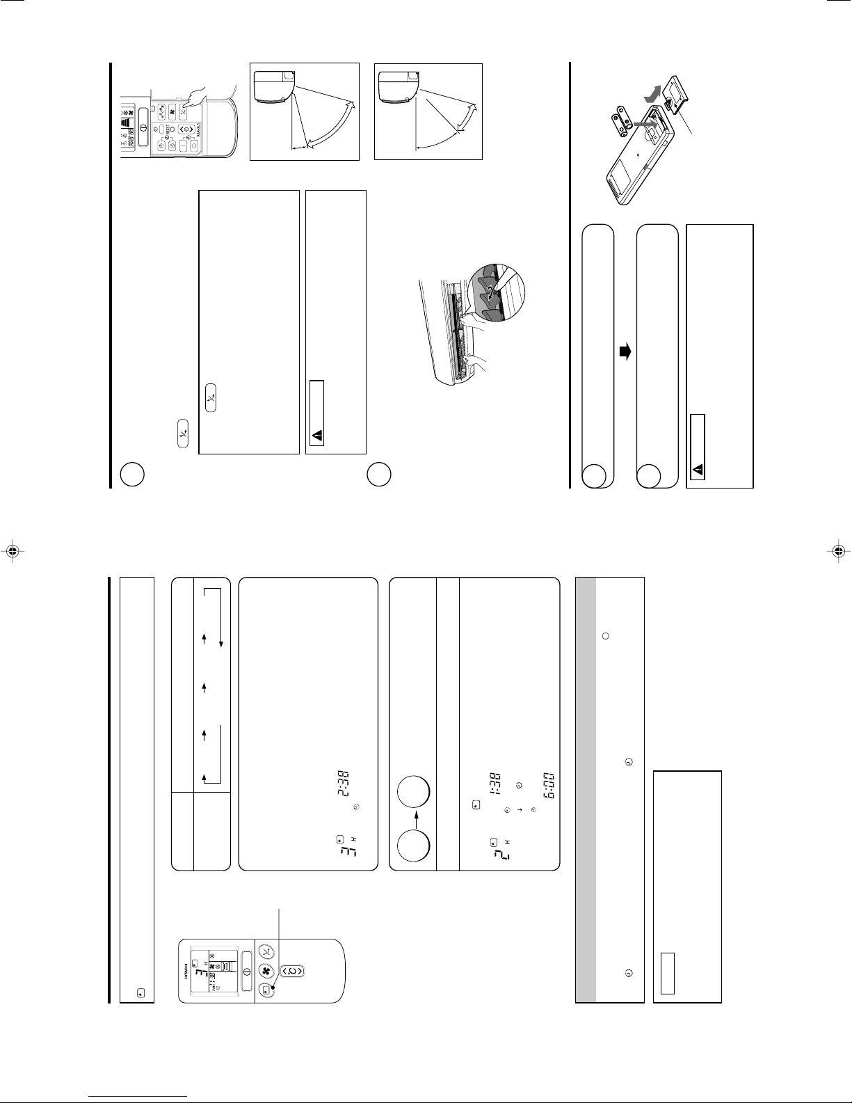
– 14 –
HOW TO SET THE SLEEP TIMER
Set the current time at first if it is not set before (see the pages for setting the current time). Press the
(SLEEP) button and the display changes as shown below.
●
SLEEP
Mode Indication
Sleep Timer
1 hour 2 hours 3 hours 7 hours
Sleep timer off
Sleep Timer: The device will continue working for the desired number of
hours and then turn off.
Point the signal window of the remote controller toward the indoor unit, and
press the SLEEP button.
The timer information will be displayed on the remote controller. The TIMER
lamp lights with a beep from the indoor unit. When the sleep timer has
been set, the display indicates the turn-off time.
AM
Example: If you set 3 hours sleep time at
11:38 p.m., the turn-off time is 2:38 a.m.
Sleep
timer
Start
The device will be turned off by the sleep timer
and turned on by on-timer.
1
Set the ON-timer.2 Press the (SLEEP) button and set the sleep timer.
AM
AM
For heating:
In this case, the device will turn off in
2 hours (at 1:38 a.m.) and turn on early
so that the preset temperature will be
almost reached at 6:00 next morning.
How to Cancel Reservation
Point the signal window of the remote controller toward the indoor unit, and press the (CANCEL)
button.
The
(RESERVED) sign goes out with a beep and the (TIMER) lamp turns off on the indoor unit.
NOTE
If you set the sleep timer when the off-time or on/off-
timer has been set earlier, the sleep timer becomes
effective instead of the off - or on/off-timer set earlier.
– 15 –
ADJUSTING THE AIR DEFLECTORS
1
Adjustment of the conditioned air in the upward and downward
directions.
The horizontal air deflector is automatically set to the proper angle
suitable for each operation. The deflector can be swung up and
down continuously and also set to the desired angle using the
“
(AUTO SWING)” button.
• In “Cooling” operation, do not keep the horizontal air
deflector swinging for a long time. Some dew may form on
the horizontal air deflector and dew may drop.
CAUTION
2
Adjustment of the conditioned air to the left and right.
Hold the vertical air deflector as shown in the figure and adjust
the conditioned air to the left and right.
HOW TO EXCHANGE THE BATTERIES IN THE REMOTE CONTROLLER
1
Remove the cover as shown in the figure and take out
the old batteries.2Install the new batteries.
The direction of the batteries should match the marks
in the case.
1. Do not use new and old batteries, or different kinds of
batteries together.
2. Take out the batteries when you do not use the remote
controller for 2 or 3 months.
CAUTION
Push and pull to the
direction of arrow.
Vertical
Vertical
about 15°
about 60°
about 45°
about 30°
When cooling,
dehumidifying
When heating
•
If the “ (AUTO SWING)” button is pressed once, the horizontal
air deflector swings up and down. If the button is pressed again, the
deflector stops in its current position. Several seconds (about 6
seconds) may be required before the deflector starts to move.
• Use the horizontal air deflector within the adjusting range
shown in the right.
• When the operation is stopped, the horizontal air deflector
moves and stops at the position where the air outlet closes.
Left side: Hold the third
blade from the left end
of the air deflector to
adjust the direction. The
pull for the blade is
marked.
Right side: Hold the third
blade from the right end
of the air deflector to
adjust the direction. The
pull for the blade is
marked.
– 11 –
– 16 –
MAINTENANCE
Cleaning and maintenance must be carried out only by qualified service personal. Before cleaning,
stop operation and switch off the power supply.
CAUTION
1. AIR FILTER
When the filter indicator lamp comes on, be sure to clean the filter. By doing so, the power rates are
saved. In case the air filter is full of dust, the air flow will decrease and the cooling capacity will be
reduced. Further, noise may occur. Be sure to clean the filter following the procedure below.
PROCEDURE
1
Open the front panel carefully and remove the filter.
2
Vacuum dust from the air filter using vacuum cleaner.
If there is too much dust, wash the filter with a detergent
and rinse it thoroughly. After that, dry it in the shade.
3
• Set the filter with “FRONT” mark facing front, and
slot them into the original state.
• After attaching the filters, push the front panel at
three arrow portions as shown in figure and close
it.
• Do not wash with hot water at more than 40°C. The filter may shrink.
• When washing it, shake off moisture completely and dry it in the shade; do not expose it directly
to the sun. The filter may shrink.
• Don't operate the unit without filter. Fault may occur if you continue.
CAUTION
– 17 –
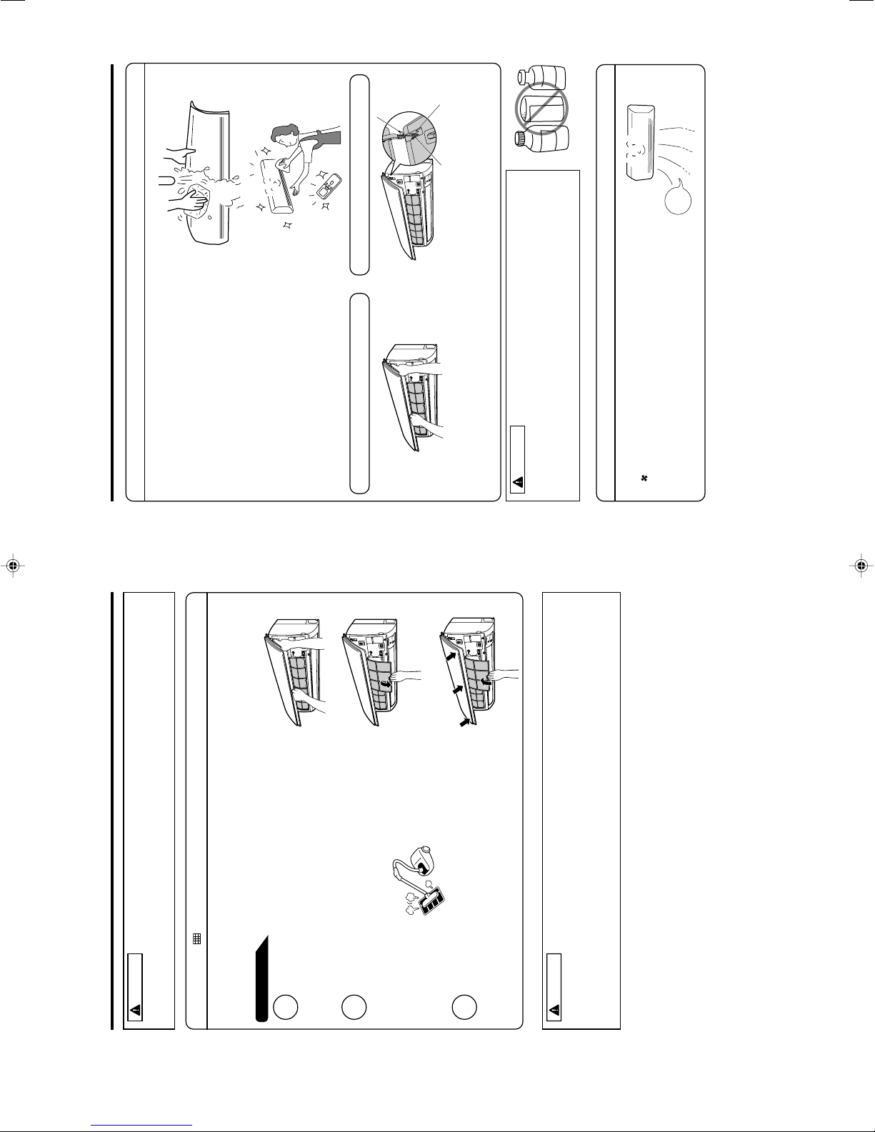
2. CLEANING OF FRONT PANEL
• Remove the front panel and wash with clean water.
Wash it with a soft sponge.
After using neutral detergent, wash thoroughly with
clean water.
• When front panel is not removed, wipe it with a soft
dry cloth. Wipe the remote controller thoroughly with
a soft dry cloth.
• Wipe the water thoroughly.
If water remains at indicators or signal receiver of
indoor unit, it causes trouble.
Method of removing the front panel.
Be sure to hold the front panel with both hands to
detach and attach it.
CAUTION
Removing the Front Panel Attaching the Front Panel
• When the front panel is fully opened with both
hands, push the right arm to the inside to
release it, and while closing the front panel
slightly, put it out forward.
• Move the shafts of the left and right arms into
the steps in the unit and securely insert them
into the holes.
Shaft
Step
Hole
• Do not splash or direct water to the body of the unit when cleaning it as
this may cause short circuit.
• Never use hot water (above 40°C), benzine, gasoline, acid, thinner or a
brush, because they will damage the plastic surface and the coating.
3. MAINTENANCE AT BEGINNING OF LONG OFF PERIOD
• Run the unit by setting the operation mode to
(FAN) and the fan speed to HI for about half a day
on a fine day, and dry the whole of the unit.
• Switch off the power plug or turn off the circuit breaker.
B
E
N
Z
I
N
E
T
H
I
N
N
E
R
A
CID
Air
Blow
– 12 –
– 18 –
INFORMATION
CAPABILITIES
Heating Capability
• This room air conditioner utilizes a heat pump system that absorbs
exterior heat and brings it into a room to be heated. As the ambient
temperature gets lower, heating capability will also lower. In such a
situation, the inverter work to increase compressor rpm to keep the
unit’s heating capability from decreasing. If the unit’s heating perfor-
mance is still unsatisfactory, other heating appliances should be used
to augment this unit’s performance.
• The air conditioner is designed to heat an entire room so that it may take some time before you feel warm.
Timer operation is recommended for effective preheating ahead of the desired time.
Cooling and Dehumidifying Capabilities
• If the heat present in a room exceeds the unit’s cooling capacity (for example, if there are many people in
the room or other heating appliances are used), the preset room temperature may not be reached.
CAUTION
Do not use a stove
or any other
hightemperature
devices in proximity
to the indoor unit.
• When fan speed, room temperature are set with the remote controller before starting manual operation and
the buttons are released, the indication of settings will go off in 10 seconds and only the operation mode
will be displayed.
• Pressing the button while the unit is in operation will let the protective circuit work so that the unit will
not operate for approximately 3 minutes.
• During heating operation, the indoor unit’s color indicator lamp may flash with no air emitted for a while.
• If you feel cold wind during heating operation with the (HI) fan speed or want to make the unit operation
quieter after the room is heated, use of (AUTO) setting is recommended.
• With the (LOW), (SILENT) settings, the unit’s cooling capacity will lower slightly.
• With the (LOW), (SILENT) settings, the unit’s fan speed of heating operation will vary with the
operating conditions.
VARIOUS FUNCTIONS
• When the timer has been programmed, the unit will not operate even if the set time is reached unless the
unit receives a signal from the remote controller. Confirm that timer programming is complete (beep) and
the TIMER lamp of the indoor unit lights.
• If the (SLEEP) button is pressed while the ON/OFF timer is programmed, the sleep timer takes priority.
• During sleep timer operation, the fan speed sets to (SILENT) regardless of the preset speed. The
remote controller display indication will remain unchanged even with the (SILENT) setting.
TIMER PROGRAMMING/SLEEP TIMER OPERATION
PROHIBITION
– 19 –
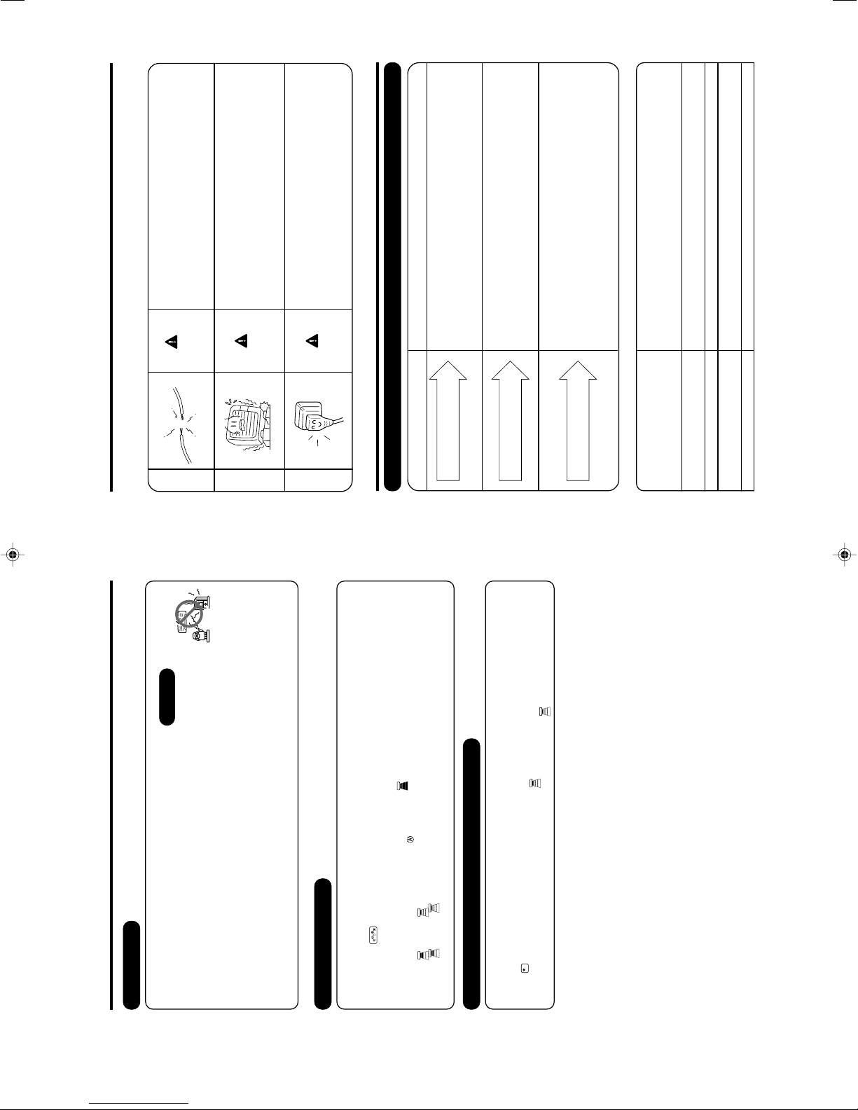
REGULAR INSPECTION
PLEASE CHECK THE FOLLOWING POINTS EVERY EITHER HALF YEARLY OR YEARLY. CONTACT
YOUR SALES AGENT SHOULD YOU NEED ANY HELP.
1
2
3
WARNING
WARNING
Check to see if the unit’s earth line has been con-
nected correctly.
If the earth line is disconnected or faulty, unit failure or
electric shock hazard may result.
Check to see if the mounting frame has rusted ex-
cessively or if the outdoor unit has tilted or become
unstable.
It could collapse or fall, causing injury.
AFTER SALES SERVICE AND WARRANTY
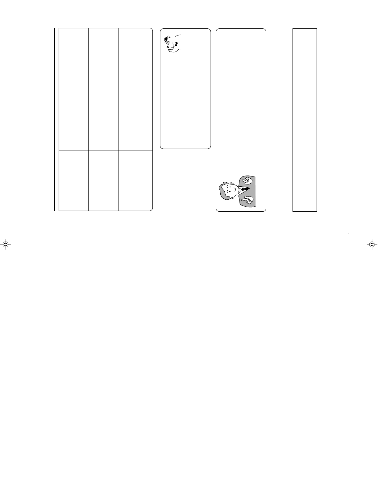
WHEN ASKING FOR SERVICE, CHECK THE FOLLOWING POINTS.
CONDITION CHECK THE FOLLOWING POINTS
• Do the batteries need replacement?
• Is the polarity of the inserted batteries correct?
• Is the fuse all right?
• Is the voltage extremely high or low?
• Is the circuit breaker “ON”?
• Is the power plug inserted?
• Do you have any power cut?
• Is the air filter blocked with dust?
• Is the set temperature suitable?
• Have horizontal air deflectors been adjusted to their correct
positions according to the operation mode selected?
• Are the air inlets or air outlets of indoor and outdoor units
blocked?
• Is the fan speed “LOW”or “SILENT”?
When it does not operate.
When it does not cool well.
When it does not heat well.
If the remote controller is not
transmitting a signal.
(Remote controller display is
dim or blank.)
■ The following phenomena do not indicate unit failure.
<Operation start>
The unit is preparing to blow warm air. Please wait.
<In operation>
The outdoor unit is defrosting. Please wait.
Refrigerant flow noise in the pipe or valve sound generated when flow rate is
adjusted.
Noise generated when the unit expands or contracts due to temperature changes.
Noise generated with the indoor unit fan’s rpm changing such as operation start
times.
Noise of the motorized valve when the unit is switched on.
During heating, the operation
indicator blinks and air blow stops
Hissing or fizzy sounds
Squeaking noise
Rustling noise
WARNING
Clicking noise
Check to see if the power plug is securely inserted
into the wall socket.
If the power plug is not inserted into the wall socket
securely or becomes hot, an electric shock or fire may result.
If dust or dirt is found on the power plug, clean the plug
and insert it into the wall socket.
– 13 –
– 20 –
• If the unit still fails to operate
normally after performing the
above inspections, turn the
circuit breaker off, or pull the
power plug out, and contact
your sales agent immediately.
Contact your sales agent immediately if the
following phenomena should occur:
•
The circuit breaker switches off or the fuse blows
frequently.•The switch operation is not stable.•Foreign matter or water accidentally enters the unit interior.•The power cord gets excessively hot or its insulation is torn or stripped.•TIMER lamp on the indoor unit display blinks.
As the nature of the failure can be identified by the blinking cycle,
check the blinking cycle before turning off the circuit breaker.
(
)
Notes
• In quiet operation or stopping the running, the following phenomena may
occasionally occur, but they are not abnormal for the operation.
(1) Slight flowing noise of refrigerant in the refrigerating cycle.
(2) Slight rubbing noise from the fan casing which is cooled and then
gradually warmed as operation stops.
• The odor will possibly be emitted from the room air conditioner because
the various odor, emitted by smoke, foodstuffs, cosmetics and so on,
sticks to it. So please clean the air filter and the evaporator regularly to
reduce the odor.
Noise of the ventilation fan sucking in air present in the drain hose and blowing out
dehumidifying water that had accumulated in the condensed water collector. For
details, consult your sales agent.
Operation noise changes due to power variations according to room temperature
changes.
Mist is generated as the air within the room is suddenly cooled by conditioned air.
Water generated during defrosting operation evaporates and steam is emitted.
Caused as the smells and particles of smoke, food, cosmetics, etc. present in room
air become attached the unit and blown off into the room again.
Defrosting is underway (as the heating operation is stopped, the microcomputer
checks frost accumulated in the outdoor unit and instructs the unit to perform
automatic defrosting if necessary).
Shows preheating or defrosting operation is underway.
As the protective circuit or preheat sensor operates when unit operation is stopped
during preheating and then restarted, or when operation mode is switched from cooling
to heating, the lamp continues to blink.
Actual room temperature may deviate slightly from the remote controller's
temperature setting depending on the number of people in the room, indoor or
outdoor conditions.
• Please contact your sales agent immediately if the air conditioner still fails to operate normally after
the above inspections. Inform your agent of the model of your unit, production number, date of
installation. Please also inform him regarding the fault.
Please note:
On switching on the equipment, particularly when the room light is dimmed, a slight brightness
fluctuation may occur. This is of no consequence.
The conditions of the local Power Supply Companies are to be observed.
Does not reach the temperature
setting
Mist emission
Perking noise
Changing operation noise
Steam emitted from the outdoor unit
The outdoor unit continues to operate
even if operation is stopped.
Odors
The OPERATION lamp is blinking.
– 14 –
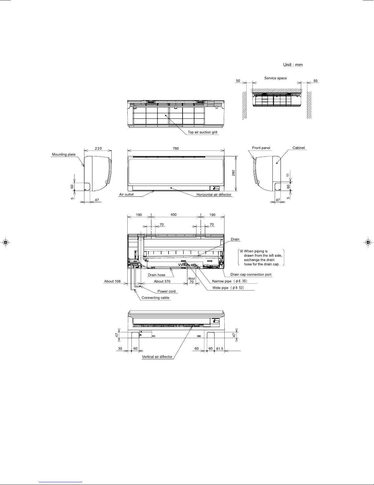
CONSTRUCTION AND DIMENSIONAL DIAGRAM
MODEL RAS-18FH6, RAS-25FH6
INDOOR UNIT
– 15 –
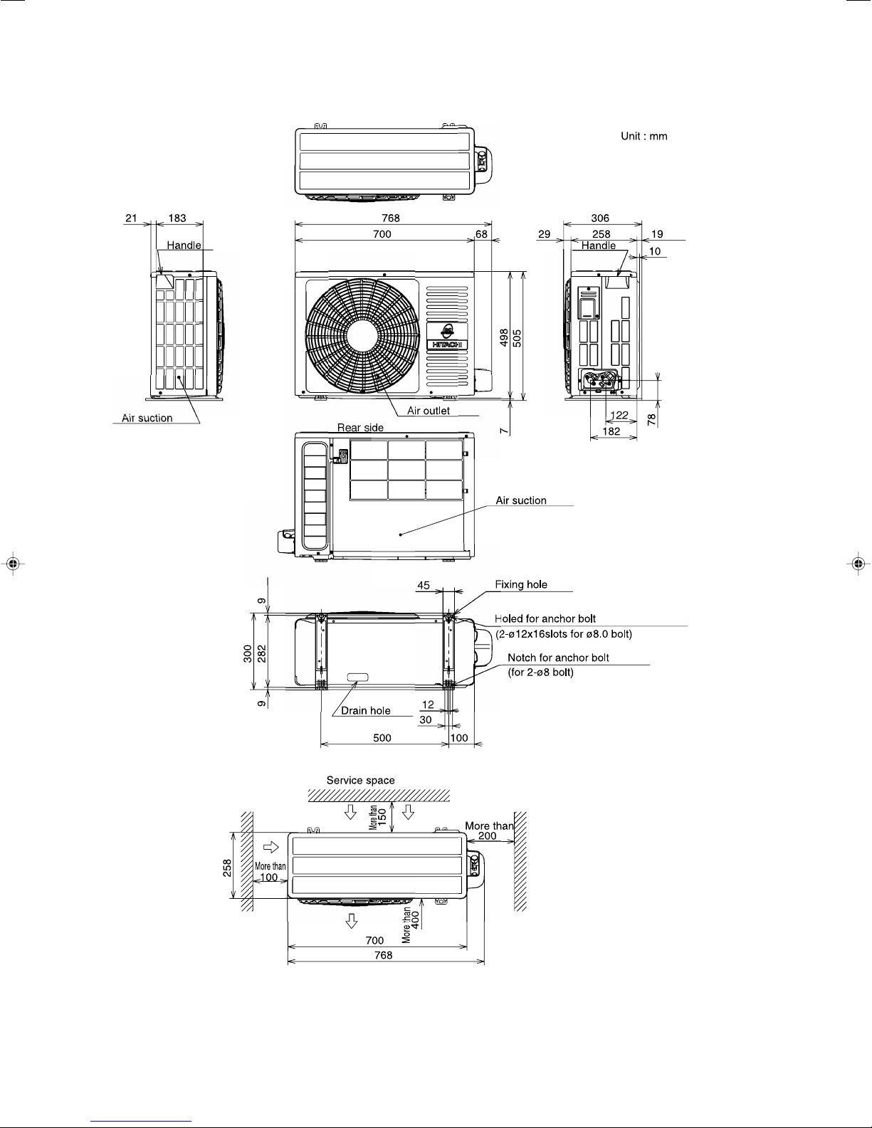
CONSTRUCTION AND DIMENSIONAL DIAGRAM
MODEL RAC-18YH6, RAC-25YH6
OUTDOOR UNIT
– 16 –
MAIN PARTS COMPONENT
THERMOSTAT
Thermostat Specifications
MODEL RAS-18FH6, RAS-25FH6
THERMOSTAT MODEL IC
OPERATION MODE COOL HEAT
ON 16.7 (62.1) 18.7 (65.7)
OFF 16.0 (60.8) 19.3 (66.7)
ON 24.7 (76.5) 26.7 (80.1)
OFF 24.0 (75.2) 27.3 (81.1)
ON 32.7 (90.9) 34.7 (94.5)
OFF 32.0 (89.6) 35.3 (95.5)
TEMPERATURE
°C (°F)
INDICATION
16
INDICATION
24
INDICATION
32
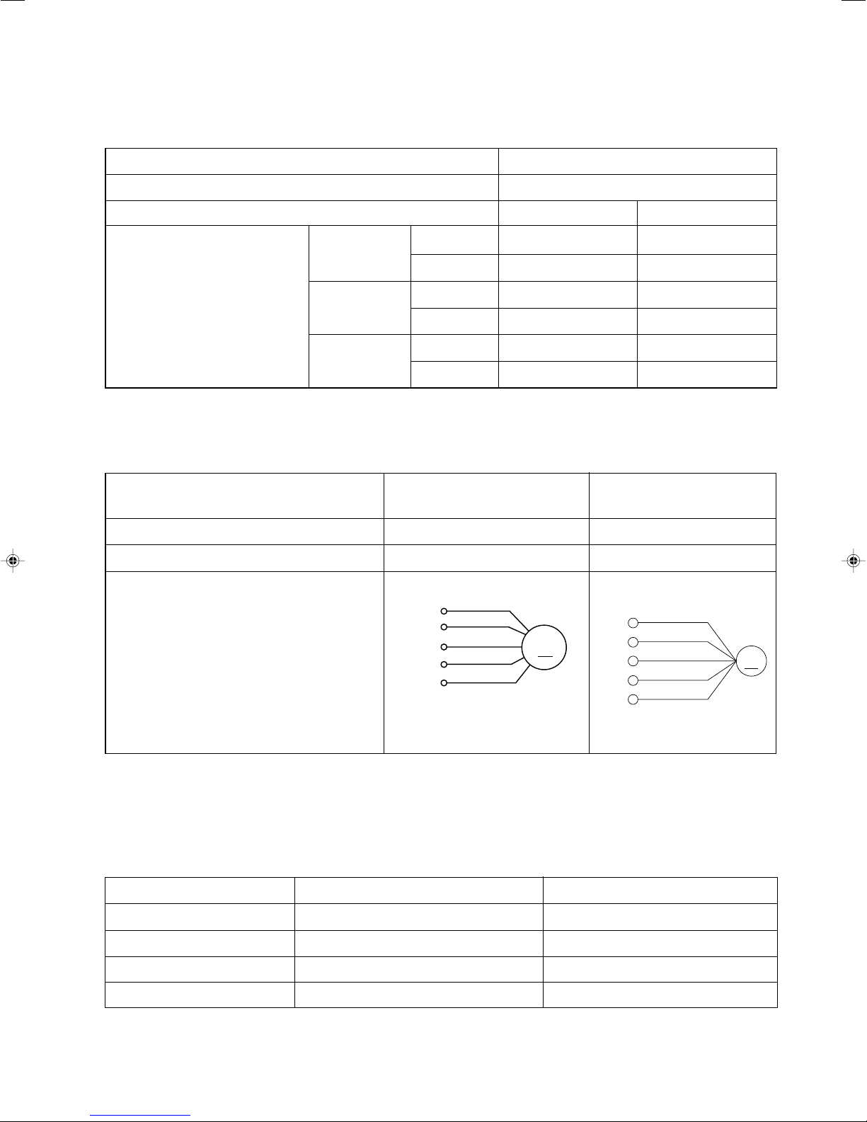
FAN MOTOR
Fan Motor Specifications
MODEL
RAS-18FH6, RAS-25FH6
POWER SOURCE DC 5V, 35V
OUTPUT 25W
RED
BLK
WHT
YEL
BLU
CONNECTION
35V
0V
5V
0 - 5V
FG
M
RAC-18YH6, RAC-25YH6
DC 140
- 350
V
40W
140 350V
15V
0-6V
0-15V
0V
RED
BLK
WHT
YEL
BLU
M
BLU : BLUE YEL : YELLOW BRN : BROWN WHT : WHITE
GRY : GRAY ORN : ORANGE GRN : GREEN RED : RED
BLK : BLACK PNK : PINK VIO : VIOLET
MAIN ELECTRIC COMPONENTS FOR OUTDOOR UNIT
NAME RATING APPLICABLE MODELS
REVERSING VALVE COIL 135 Ω (20 ˚C) RAC-18YH6, 25YH6
REACTOR L1 13 (mH), 0.224 Ω RAC-18YH6, 25YH6
REACTOR L2 25.5 (mH), 0.37 Ω RAC-18YH6, 25YH6
FILM CAPACITOR 45 (µF) RAC-18YH6, 25YH6
(Control circuit built in)
– 17 –
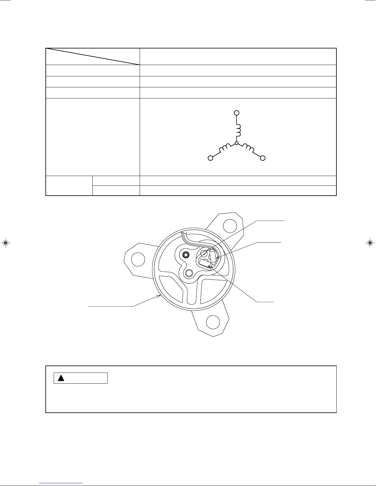
COMPRESSOR MOTOR
Compressor Motor Specifications
ITEM
COMPRESSOR TYPE
POWER SOURCE
OUTPUT
WINDING
RESISTANCE
(Ω)
20°C
75°
MODEL
C
RAC-18YH6, RAC-25YH6
ASC092CD
DC 220 - 350 V
800W
(U)
WHITE
M
(V)
M
YELLOW
M
2M=1.15
2M=1.40
(W)
RED
YELLOW
WHITE
RED
!
CAUTION
COMPRESSOR
FRONT SIDE OF OUTDOOR UNIT
When the refrigerating cycle has been operated for a long time with the capillary tubes clogged or crushed
or with too little refrigerant, check the color of the refrigerating machine oil inside the compressor. If the
color has been changed conspicuously, replace the compressor.
– 18 –
– 19 –
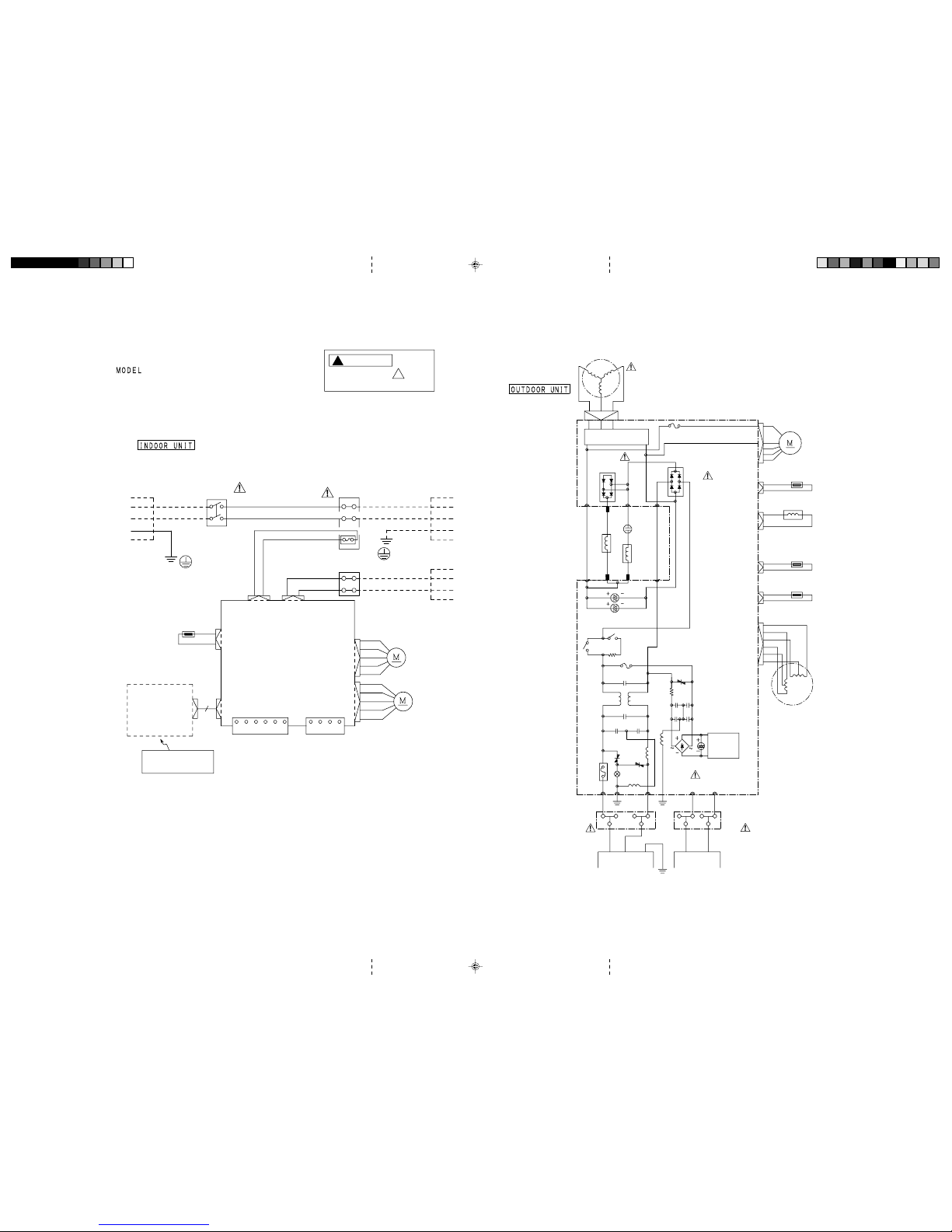
WIRING DIAGRAM
RAS-18FH6 / RAC-18YH6
RAS-25FH6
/
RAC-25YH6
!
!
CAUTION
The marked parts are
very important ones for safety.
BLU : BLUE ORN : ORANGE
BLK : BLACK RED : RED
BRN : BROWN WHT : WHITE
GRN : GREEN YEL : YELLOW
GRY : GRAY
COMPRESSOR
WHT
YEL
RED
CN1
U
VW
P
N
I P M
1 A FUSE
D I O D E
S T A C K
(DB3)
D I O D E S T A C K
(DB2)
CN 24
(WHT)
CN 8
(WHT)
CN 2
(RED)
CN 9
(BLK)
CN 10
(RED)
CN 15
(WHT)
O U T D O O R
F A N M O T O R
OVERHEAT THERMISTOR
RED
RED
BLK
BLK
REVERSING VALVE
DEFROST THERMISTOR
GRY
GRY
OUTDOOR TEMP.
THERMISTOR
GRY
GRY
WHT
YEL
ORN
BLU
BRN
RED
E L E C T R I C
E X P A N S I O N V A L V E
M A I N P. W. B.
TAB 0 5
REACTOR L1
REACTOR L2
GRY
TAB 11
TAB 11
ORN
BLU
BLU
YEL
YEL
CAPACITOR
375ʚFĻ2
SMOOTHING CAPACITOR
RL 1
RL 2
ICP RELAY
R007
RELAY
POWER
3 A FUSE
R 0 0 2
C 0 1 1
L 1 0 1
C 0 0 1
1 5 A
FUSE
C 0 0 3
C 0 0 2
C 0 1 2
C 0 0 7
V S 2
C 0 1 3
C 0 0 8
L 0 0 2
V S 1
C 4 1
POWER
SWITCHING
SUPPLY
C T 1
V S 3
S A 1
L 0 0 1
S T A C K
D I O D E
(DB1)
RED
BRN
FRAME
GRN 1
BLK
WHT
TERMINAL
BOARD
TERMINAL
BOARD
(GRN + YEL)
(WHT)
(BLK)
(BRN)
(RED)
L
( A )
N
( B )
C
D
I N D O O R
U N I T
I N D O O R
U N I T
C O N T R O L
P . W . B .
C N 4
C N 3
C N 8
(WHT)
C N 1 0
RED
BLACK
WHITE
YELLOW
BLUE
C N 1
W i r e d
R e m o c o n
C N 9
C N 7
H Ĺ L I N K
C N 2
GRAY
GRAY
BROWN
RED
C
D
A
B
(BROWN)
(RED)
(GREEN & YELLOW)
(BLACK)
(WHITE)
CONNECTING
CORD
TERMINAL
BOARD
POWER
SWITCH
3
1
4
2
BLACK
WHITE
BROWN
BLUE
GREEN & YELLOW
SINGLE PHASE
AC220 Ĺ 230V
50Hz
L I N E
CORD
AUTO SWEEP
MOTOR
I N D O O R
F A N MOTOR
0V
1 2V
R e c
S e n d
1
2
3
4
1
2
3
4
5
6
1 2 V
R x
0 V
T x
THERMAL
FUSE (102Ŋ)
HEAT
EXCHANGER
THERMISTOR
( ROOM TEMP.
THERMISTOR )
INDICATING
RECIEVER
P . W . B .
C N 2
1 2
WIRELESS REMOTE
CONTROL
RAS_AW_019A3 2008.02.18, 10:0719
– 20 –
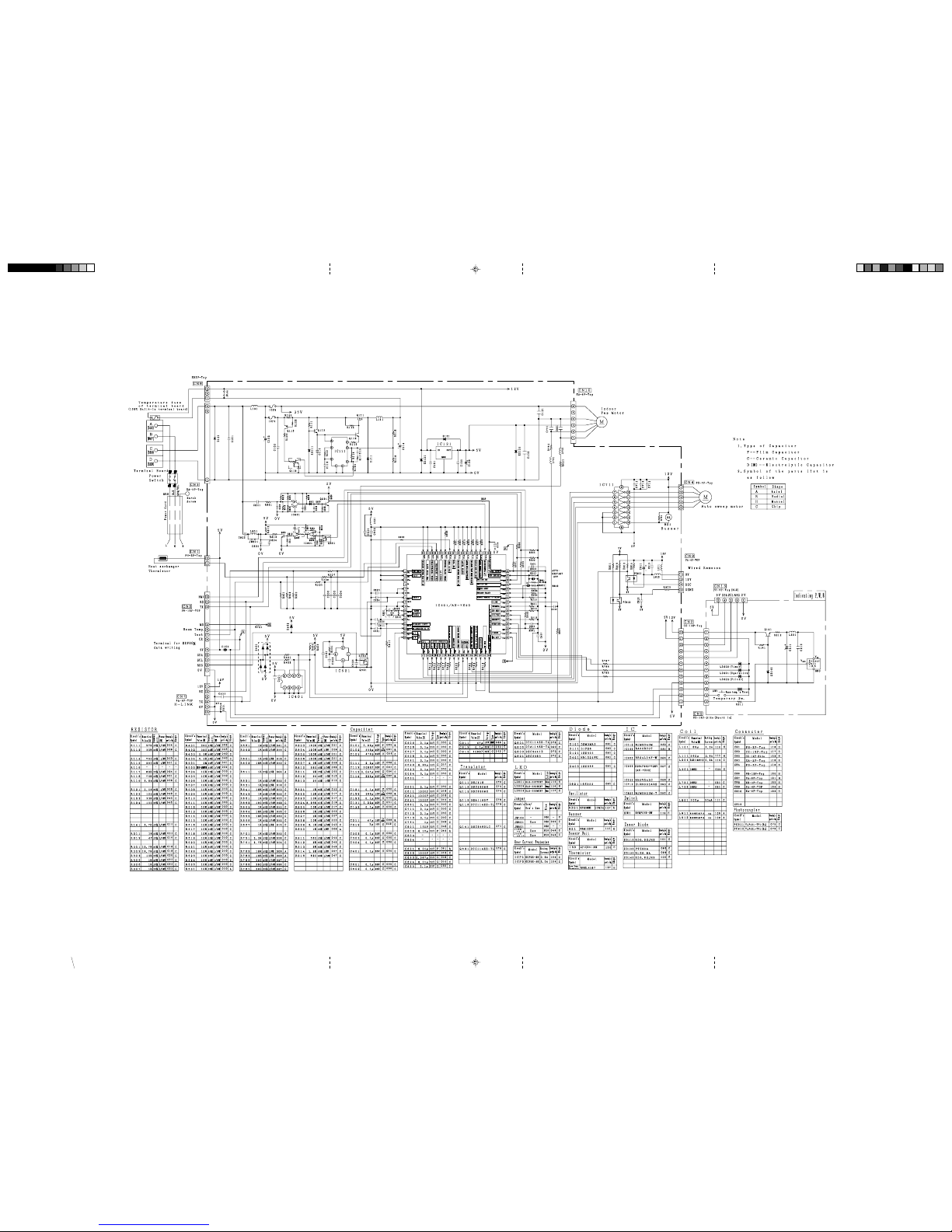
CIRCUIT DIAGRAM
MODEL RAS-18FH6, RAS-25FH6
RAS_AW_020-021_A2 2008.02.18, 10:1720
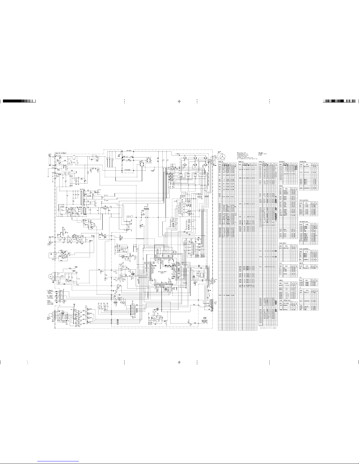
– 21 –
RAC-18YH6, RAC-25YH6
MODEL
RAS_AW_020-021_A2 11/17/06, 11:18 AM21
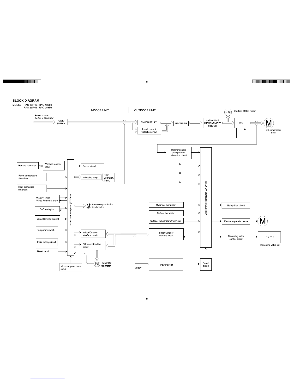
– 22 –
RAS_AW_022_A3e 2008.02.19, 16:3322

– 23 –
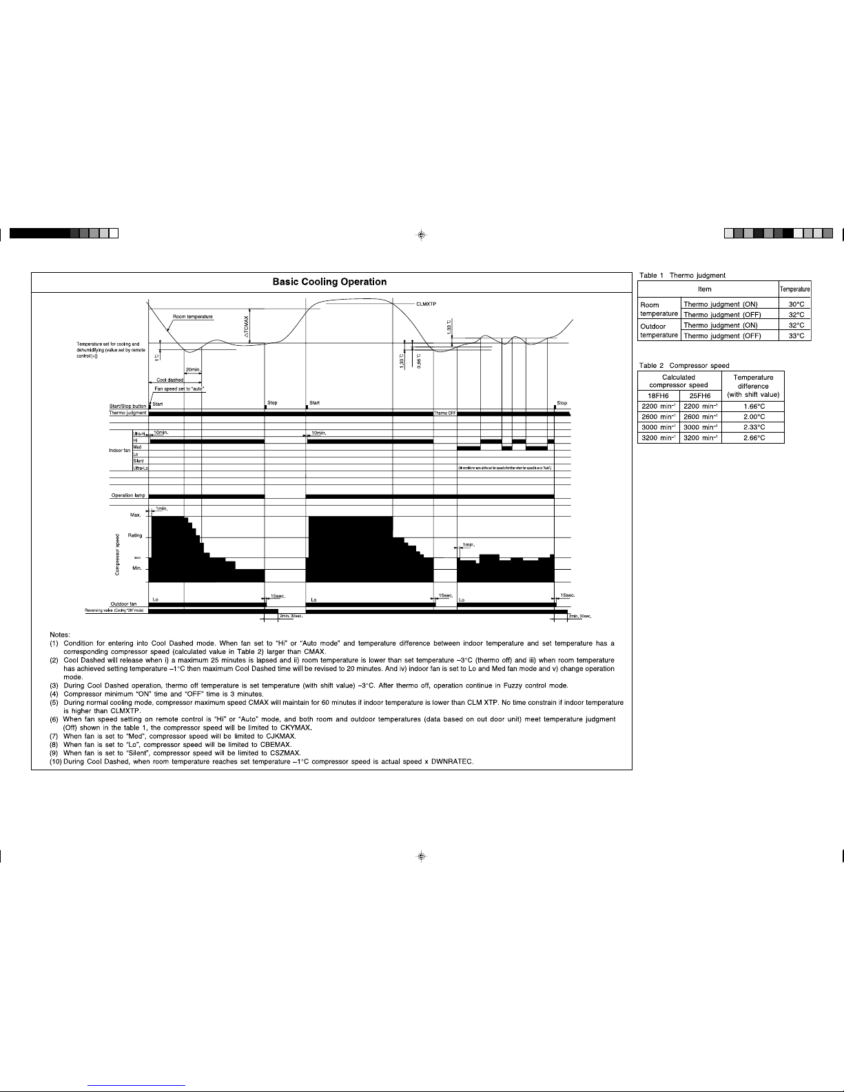
Silent
RAS_AW_023_A3e 2008.03.06, 20:5823
Table 1 Mode data file
RAS-18FH6 RAS-25FH6
LABEL NAME VALUE
WMAX
WMAX2
WSTD
WJKMAX
WBEMAX
WSZMAX
CMAX
CSTD
CKYMAX
CJKMAX
CBEMAX
CSZMAX
WMIN
CMIN
3500 min
3500 min
2950 min
2800 min
2800 min
2800 min
3200 min
2400 min
2300 min
2300 min
2300 min
2200 min
2200 min
2200 min
-1
-1
-1
-1
-1
-1
-1
-1
-1
-1
-1
-1
-1
-1
4400 min
4400 min
4200 min
3500 min
3200 min
3200 min
3200 min
2900 min
2700 min
2500 min
2300 min
2200 min
2200 min
2200 min
-1
-1
-1
-1
-1
-1
-1
-1
-1
-1
-1
-1
-1
-1
STARTMC
DWNRATEW
DWNRATEC
SHIFTW
SHIFTC
CLMXTP
YNEOF
TEION
TEIOF
SFTDSW
DFTIM1
DFTIM2
90 Seconds 90 Seconds
80% 80%
60% 60%
2.00°C 2.00°C
1.33°C 1.33°C
30.00°C 30.00°C
25.00°C 25.00°C
2.00°C 2.00°C
9.00°C 9.00°C
1.00°C 1.00°C
43 Minutes 43 Minutes
60 Minutes 60 Minutes
– 24 –
– 25 –
– 26 –
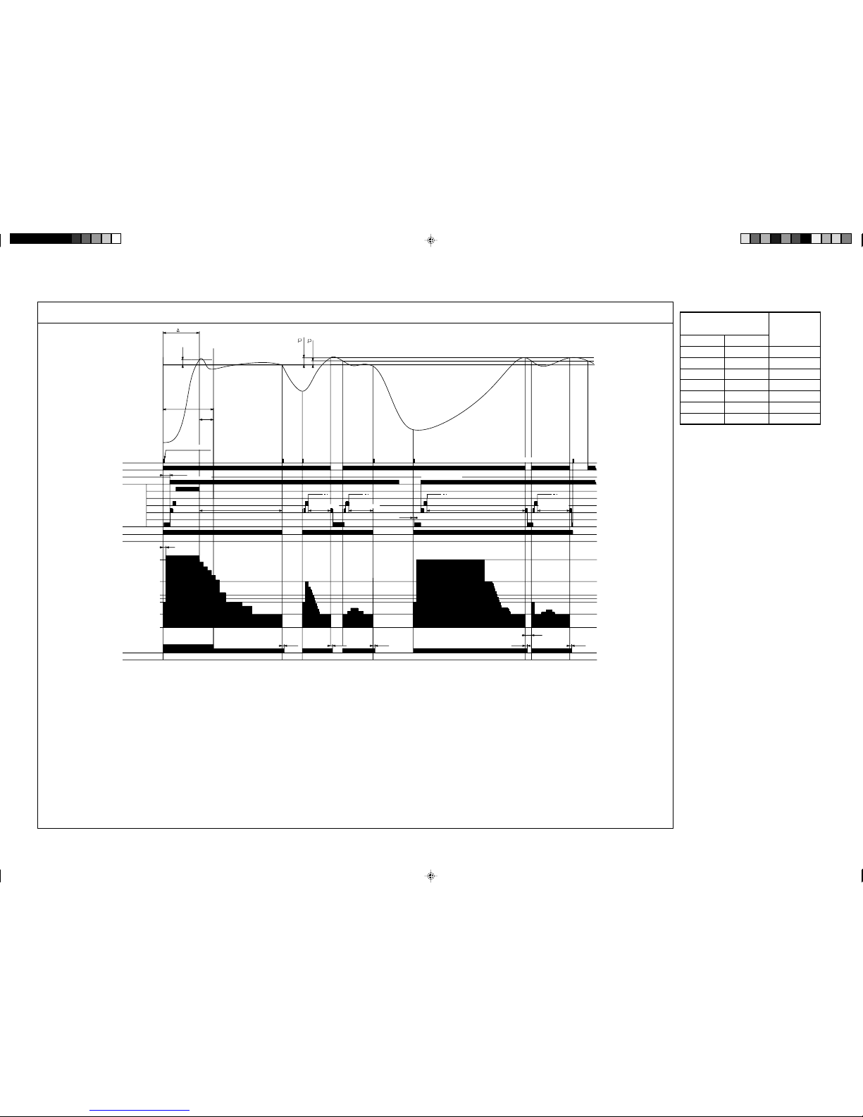
Basic Heating Operation
Notes:
(1) Condition for entering into Hot Dashed mode. When fan set to “Hi” or “Auto mode” and i) Indoor temperature is lower than 18°C, and ii) outdoor temperature is lower than 10°C,
and iii) Temperature difference between indoor temperature and set temperature has a corresponding compressor speed (calculated value in Table 3) larger than WMAX.
(2) Hot Dashed will release when i) Room temperature has achieved the set temperature + SFTDSW. ii) Thermo off.
(3) During Hot Dashed operation, thermo off temperature is set temperature (with shift value) +3°C. After thermo off, operation continue in Fuzzy control mode.
(4) Compressor minimum “ON” time and “OFF” time is 3 minutes.
(5) During normal heating mode, compressor maximum speed WMAX will maintain for 120 minutes if indoor temperature is higher than 18°C. No time limit constrain if outdoor temperature
is lower than 4°C.
(6) During Hotkeep or Defrost mode, indoor operation lamp will blink at interval of 0.5 seconds “ON” and 0.5 second “OFF”.
(7) When heating mode starts, it will enter into Hotkeep mode if indoor heat exchanger temperature is lower than YNEOF + 0.33°C.
(8) When fan is set to
compressor speed will be limited to WSZMAX.
“Lo”, compressor speed will be limited to WBEMAX. When fan is set to "Med", compressor speed will be limited to WJKMAX. When fan is set to “Silent”,
(9) In “Ultra-Lo” fan mode, if indoor temperature is lower than 18°C, indoor fan will stop. If indoor temperature is higher than 18°C + 0.33°C, fan will continue in “Ultra-Lo” mode.
During Hotkeep or Defrost mode, fan will continue in “Ultra-Lo” mode.
(10) During Hot Dashed, when room temperature reaches set temperature + SFTDSW compressor speed is actual speed x DWNRATEW.
Table 3 Compressor speed
Notes:
1. See the data in Table 1-Table 2 on
page 47 & 49 for each constant in
capital letters in the diagrams.
Temperature
difference
(with shift value)
Calculated
compressor speed
1.66°C
2200 min
–1
2.00°C
2600 min
–1
2.33°C
3000 min
–1
2.66°C
3.00°C
3400 min
–1
3500 min
–1
18FH6 25FH6
3.33°C
3500 min
–1
3.66°C
3500 min
–1
2200 min
–1
2600 min
–1
3000 min
–1
3400 min
–1
3800 min
–1
4200 min
–1
4400 min
–1
1.33
0.66
10sec.
60sec.
WMAX2
Hi
Lo
15sec.
15sec.
15sec.
Lo Lo Lo
15sec. 15sec.
3min.
Lo
3000
SFTDSW
WMIN
Indoor fan
Operarion lamp
Ultra-Hi
Hi
Med
Lo
Silent
Ultra-Lo
Max.
Rating
Min.
Outdoor fan
Start/Stop button
Thermo judgment
Defrost signal
Preheating judgment
Heating set temperature
(remote control set temperature
(+))
Fan speed set to "auto"
Start
Max.3 min.
Preheating released
Preheating released
Control by heat exchanger temperature
Control by heat exchanger temperature
Control by
heat exchanger temperature
Control by
heat exchanger temperature
Control by
heat exchanger temperature
Thermo OFF
Thermo
OFF
Thermo
OFF
Stop
Start
Stop
Start
Stop
Compressor speed
Dashed period
td
20min.
Reversing valve
(Cooling "ON" mode)
– 27 –
RAS_AW_025-028_A3e 2008.02.19, 16:3027
 Loading...