

Hitachi RAS-18GH5, RAC-18GH5 Service Manual
NO. 0479E
SPECIFICATIONS AND PARTS ARE SUBJECT TO CHANGE FOR IMPROVEMENT
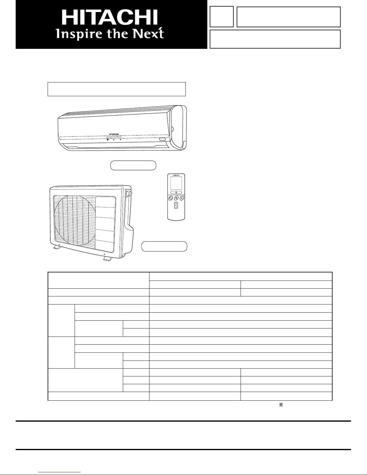
ROOM AIR CONDITIONER
INDOOR UNIT + OUTDOOR UNIT
JANUARY 2011
Refrigeration & Air-Conditioning Division
SERVICE MANUAL
PM
REFER TO THE FOUNDATION MANUAL
TECHNICAL INFORMATION
FOR SERVICE PERSONNEL ONLY
(W)
(A)
(kW)
(B.T.U./h)
(W)
(A)
(kW)
(B.T.U./h)
W
H
D
(kg)
RAS-18GH5 RAC-18GH5
(WALL TYPE)
TYPE
MODEL
POWER SOURCE
TOTAL INPUT
TOTAL AMPERES
CAPACITY
TOTAL INPUT
TOTAL AMPERES
CAPACITY
DIMENSIONS
(mm)
NET WEIGHT
SPECIFICATIONS
1030
295
207
12
RAS-18GH5
CONTENTS
SPECIFICATIONS ----------------------------------------------------- 5
HOW TO USE ---------------------------------------------------------- 9
CONSTRUCTION AND DIMENSIONAL DIAGRAM ---------30
MAIN PARTS COMPONENT --------------------------------------32
WIRING DIAGRAM ---------------------------------------------------34
CIRCUIT DIAGRAM --------------------------------------------------35
PRINTED WIRING BOARD LOCATION DIAGRAM --------37
BLOCK DIAGRAM ----------------------------------------------------39
BASIC MODE ----------------------------------------------------------41
REFRIGERATING CYCLE DIAGRAM --------------------------47
DESCRIPTION OF MAIN CIRCUIT OPERATION ----------48
AUTO SWING FUNCTION -----------------------------------------52
SERVICE CALL Q & A ---------------------------------------------53
TROUBLE SHOOTING ----------------------------------------------59
PARTS LIST AND DIAGRAM -------------------------------------62
RAS-18GH5/RAC-18GH5
RAC-18GH5
COOLING
HEATING
INDOOR UNIT OUTDOOR UNIT
1 Ø, 50 Hz, 220 ~ 230
1550 ~ 1580
7.42 ~ 7.23
5.10
17,410
1640 ~ 1680
7.77 ~ 7.61
5.75
19,630
850
650
298
47
After installation

– 1 –
SAFETY DURING REPAIR WORK
1. In order to disassemble and repair
the unit in question, be sure to
disconnect the power cord plug
from the power outlet before starting
the work.
2. If it is necessary to replace any
parts, they should be replaced with respective genuine parts for the unit, and the replacement must be effected in correct manner according to the instructions in the Service Manual of the unit.
If the contacts of electrical
parts are defective, replace the
electrical parts without trying to
repair them.
3. After completion of repairs, the initial state
should be restored.
4. Lead wires should be connected and laid as
in the initial state.
5. Modifi cation of the unit by user himself should
absolutely be prohibited.
6. Tools and measuring instruments for use in repairs or inspection should be accurately calibrated in advance.
7. In installing the unit having been repaired, be careful to prevent the occurence of any accident such as
electrical shock, leak of current, or bodily injury due to the drop of any part.
8. To check the insulation of the unit, measure the insulation resistance between the power cord plug and
grounding terminal of the unit. The insulation resistance should be 1M or more as measured by a 500V
DC megger.
9. The initial location of installation such as window, fl oor or the other should be checked for being and safe
enough to support the repaired unit again.
If it is found not so strong and safe, the unit should be installed at the initial location reinforced or at a new
location.
10. Any infl ammable thing should never
be placed about the location of
installation.
11. Check the grounding to see whether
it is proper or not, and if it is found
improper, connect the grounding
terminal to the earth.
DANGER
First, I must disconnect
the power cord plug
from the power outlet.
– 2 –
WORKING STANDARDS FOR PREVENTING BREAKAGE OF SEMICONDUCTORS
1. Scope
The standards provide for items to be generally observed in carrying and handling semiconductors in rela-
tive manufacturers during maintenance and handling thereof. (They apply the same to handling of abnormal
goods such as rejected goods being returned).
2. Object parts
(1) Micro computer
(2) Integrated circuits (IC)
(3) Field-effect transistors (FET)
(4) P.C. boards or the like on which the parts mentioned in (1) and (2) of this paragraph are equipped.
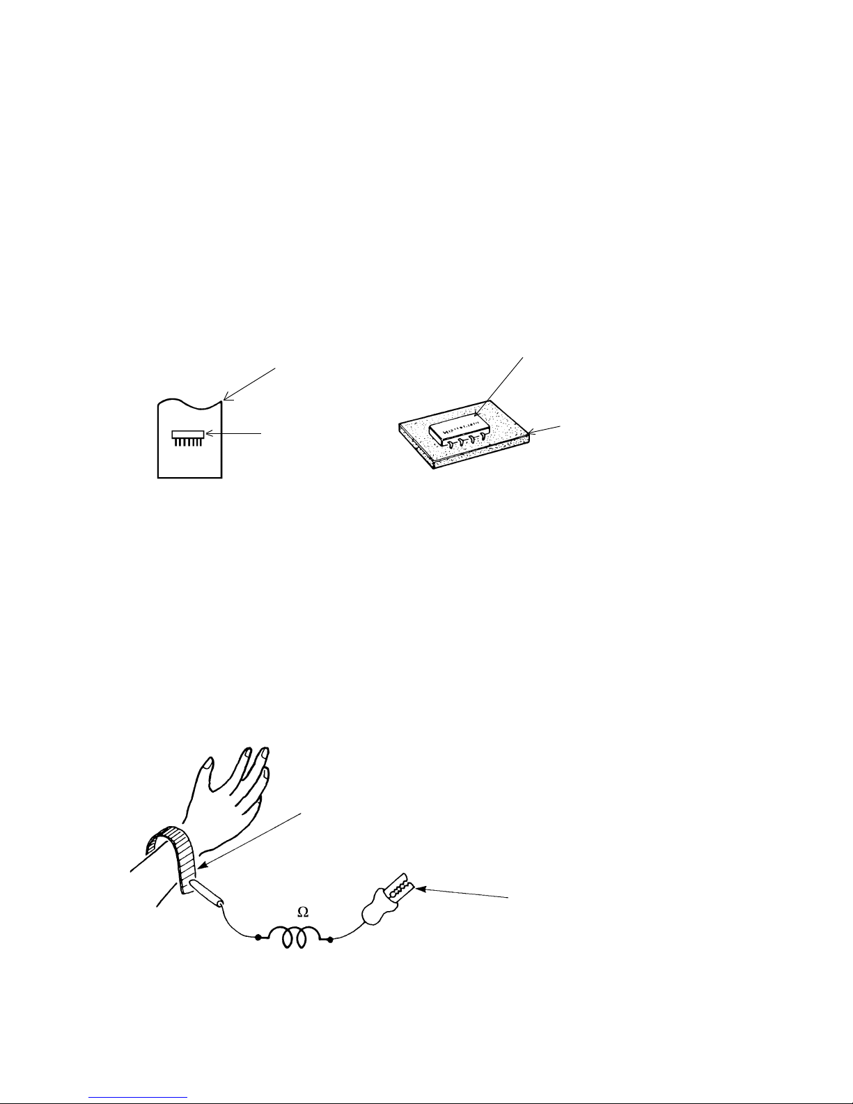
3. Items to be observed in handling
(1) Use a conductive container for carrying and storing of parts. (Even rejected goods should be handled
in the same way).
Fig. 1. Conductive Container
(2) When any part is handled uncovered (in counting, packing and the like), the handling person must al-
ways use himself as a body earth. (Make yourself a body earth by passing one M ohm earth resistance
through a ring or bracelet).
(3) Be careful not to touch the parts with your clothing when you hold a part even if a body earth is being
taken.
(4) Be sure to place a part on a metal plate with grounding.
(5) Be careful not to fail to turn off power when you repair the printed circuit board. At the same time, try
to repair the printed circuit board on a grounded metal plate.
1M
Fig. 2. Body Earth
Body earth
(Elimik conductive band)
Clip for connection with a
grounding wire
IC
A conductive polyvinyl bag
IC
Conductive sponge
– 3 –
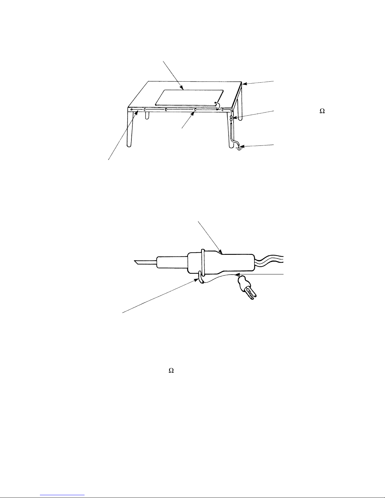
(6) Use a three wire type soldering iron including a grounding wire.
Bare copper wire (for body earth)
Working
table
Resistor of 1 M (1/2W)
Earth wire
Fig. 3. Grounding of the working table
Screw stop at the screwed
part using a rag plate
Soldering iron
Grounding
wire
Fig. 4. Grounding a soldering iron
Use a high insulation mode (100V, 10M or higher) when ordinary iron is to be used.
(7) In checking circuits for maintenance, inspection or some others, be careful not to have the test probes of
the measuring instrument shortcircuit a load circuit or the like.
Metal plate (of aluminium, stainless steel, etc.)
Staple

– 4 –
1. In quiet or stop operation, slight fl owing noise of refrigerant in the refrigerating cycle is heard occasionally,
but this noise is not abnormal for the operation.
2. When it thunders near by, it is recommended to stop the operation and to disconnect the power cord plug
from the power outlet for safety.
3. In the event of power failure, the air conditioner will restart automatically in the previously selected mode
once the power is restored. In the event of power failure during TIMER operation, the timer will be reset
and the unit will begin or stop operating under a new timer setting.
4. If the room air conditioner is stopped by adjusting thermostat, or missoperation, and re-start in a moment,
there is occasion that the cooling and heating operation does not start for 3 minutes, it is not abnormal
and this is the result of the operation of IC delay circuit. This IC delay circuit ensures that there is no
danger of blowing fuse or damaging parts even if operation is restarted accidentally.
5. This room air conditioner should not be used at the cooling operation when the outside temperature is
below 10°C (50°F).
6. This room air conditioner (the reverse cycle) should not be used when the outside temperature is below
–10°C (14°F).
If the reverse cycle is used under this condition, the outside heat exchanger is frosted and effi ciency falls.
7. When the outside heat exchanger is frosted, the frost is melted by operating the hot gas system, it is not
trouble that at this time fan stops and the vapour may rise from the outside heat exchanger.
!
CAUTION
– 5 –
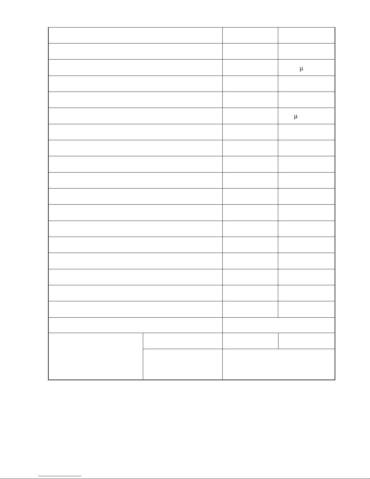
RAC-18GH5
40 W
2.5 F,450V
YES (INTERNAL)
5KS205DAA
50 F, 450VAC
YES (INTERNAL)
YES (INTERNAL)
NO
NO
NO
NO
NO
NO
NO
NO
YES(IC)
NO
SPECIFICATIONS
MODEL
FAN MOTOR
FAN MOTOR CAPACITOR
FAN MOTOR PROTECTOR
COMPRESSOR
COMPRESSOR MOTOR CAPACITOR
OVERLOAD PROTECTOR
OVERHEAT PROTECTOR
FUSE (MICRO COMPUTER CIRCUIT)
POWER RELAY
POWER SWITCH
TEMPORARY SWITCH
SERVICE SWITCH
TRANSFORMER
VARISTOR
NOISE SUPPRESSOR
THERMOSTAT
REMOTE CONTROL SWITCH (LIQUID CRYSTAL)
FUSE CAPACITY
RAS-18GH5
30 W
NO
NO
–
NO
NO
NO
3.15A
G4A
YES
NO
YES
NO
450NR
NO
YES(IC)
YES
20 A TIME DELAY FUSE
----------
❈ 1450g
UNIT
PIPES (MAX. 15m)
REFRIGERANT CHARGING
VOLUME
(Refrigerant R410A)
PIPES (MIN. 5m)
ADDITIONAL REFRIGERANT R410A
AT 15g PER EVERY METER IF
PIPE LENGTH MORE THAN 8m.
– 6 –
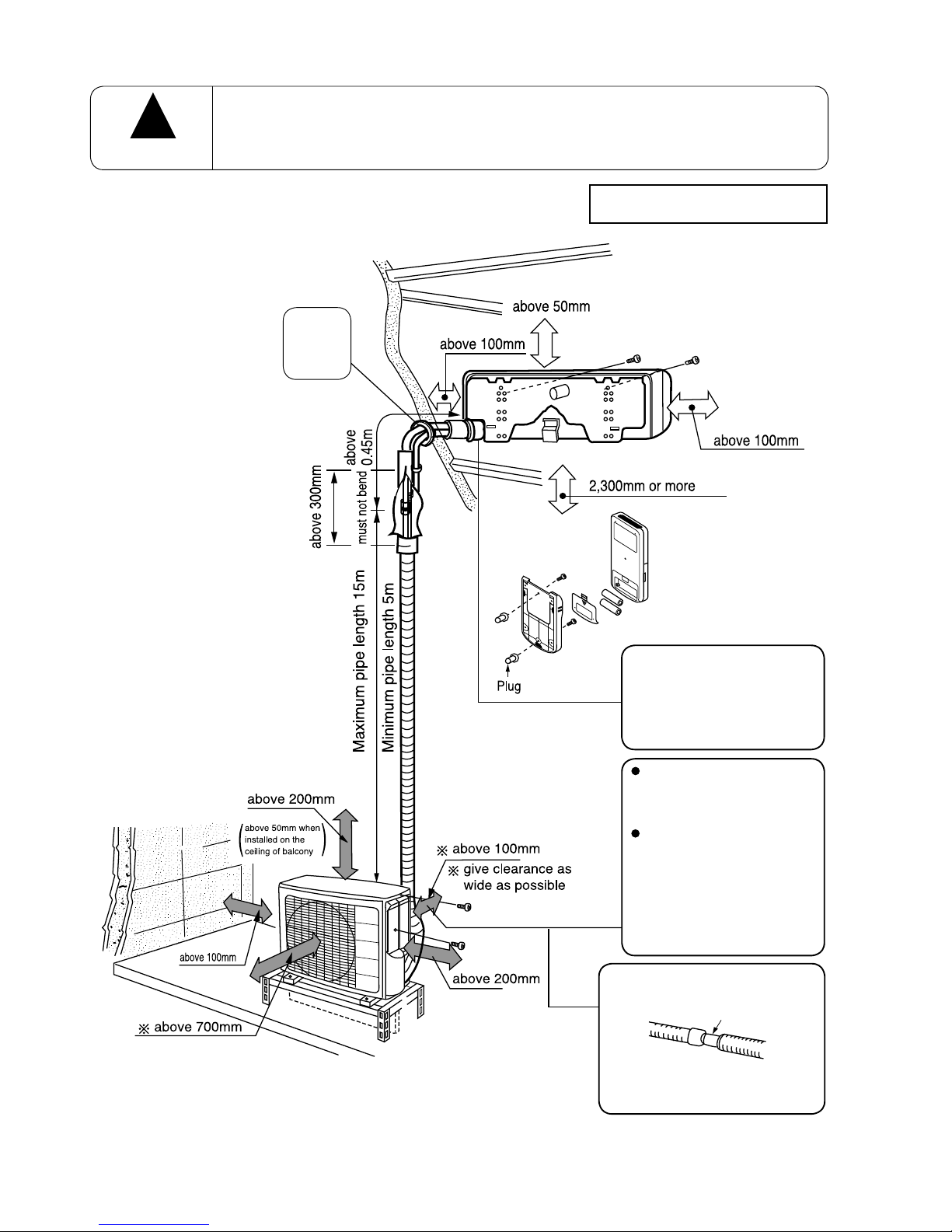
Figure showing the installation of Indoor and Outdoor unit
The installation height of indoor unit must be 2.3m or more in a non public area
CAUTION
!
The indoor piping should
be insulated with the enclosed insulation pipe. (If the
insulator is insufficient,
please use commersial
products).
inner diameter ø 16mm
The connection of insulated
drain hose.
Please use insulated drain
hose for the indoor piping
(commercial product).
The difference in height
between the indoor and
outdoor unit should be
kept max 10m.
The connecting pipe,
no matter big or small,
should all be insulated
with insulation pipe and
then warapped with vinyl
tape. (The insulator will
deteriorate if it is not
wrapped with tape).
Figure showing the Installation
of Indoor and Outdoor Unit.
Be sure to
completely
seal any
gap with
putty.
– 7 –
!
!
SAFETY PRECAUTION
●
Please read the “Safety Precaution” carefully before operating the unit to ensure correct usage of the unit.
●
Pay special attention to signs of “ Warning” and “ Caution”. The “Warning” section contains matters
which, if not observed strictly, may cause death or serious injury. The “Caution” section contains matters which
may result in serious consequences if not observed properly. Please observe all instructions strictly to ensure
safety.
●
The sign indicate the following meanings.
●
Please keep this manual after reading.
Make sure to connect earth line.
Indicates the instructions that must be followed.
The sign in the fi gure indicates prohibition.
PRECAUTIONS DURING OPERATION
● Avoid an extended period of direct air fl ow for your health.
W
A
R
N
I
N
G
!
● Do not insert a fi nger, a rod or other objects into the air outlet or inlet. As
the fan is rotating at a high speed, it will cause injury. Before cleaning, be
sure to stop the operation and turn the breaker OFF.
● During thunder storm, disconnect and turn off the circuit breaker.
● Do not use any conductor as fuse wire, this could cause fatal accident.
WARNING
PRECAUTIONS DURING INSTALLATION
●
Do not reconstruct the unit.
Water leakage, fault, short circuit or fi re may occur if you reconstruct the unit by
yourself.
●
Please ask your sales agent or qualifi ed technician for the installation of your unit.
Water leakage, short circuit or fi re may occur if you install the unit by yourself.
●
Please use earth line.
Do not place the earth line near water or gas pipes, lightning-conductor, or the
earth line of telephone. Improper installation of earth line may cause electric
shock.
●
Be sure to use the specifi ed piping set for R410A. Otherwise, this may result in
broken copper pipes or faults.
●
A circuit breaker should be installed depending on the mounting site of the unit.
Without a circuit breaker, the danger of electric shock exists.
●
Do not install near location where there is fl ammable gas. The outdoor unit may
catch fi re if fl ammable gas leaks around it.
●
Please ensure smooth fl ow of water when installing the drain hose.
CAUTION
!
!
PRECAUTIONS DURING SHIFTING OR MAINTENANCE
● Should abnormal situation arises (like burning smell), please stop operating the unit
and turn off the circuit breaker. Contact your agent. Fault, short circuit or fi re may
occur if you continue to operate the unit under abnormal situation.
● Please contact your agent for maintenance. Improper self maintenance may cause
electric shock and fi re.
● Please contact your agent if you need to remove and reinstall the unit. Electric
shock or fi re may occur if you remove and reinstall the unit yourself improperly.
● If the supply cord is damaged, it must be replaced by the special cord
obtainable at authorized service/parts centers.
W
A
R
N
I
N
G
!
– 8 –
PRECAUTIONS DURING OPERATION
● Do not attempt to operate the unit with wet hands, this could cause fatal
accident.
● When operating the unit with burning equipments, regularly ventilate the
room to avoid oxygen insuffi ciency.
● Do not direct the cool air coming out from the air-conditioner panel to face
household heating apparatus as this may affect the working of apparatus
such as the electric kettle, oven etc.
● Do not place plants directly under the air fl ow as it is bad for the plants.
● Please ensure that outdoor mounting frame is always stable, fi rm and
without defect. If not, the outdoor unit may collapse and cause danger.
● Do not splash or direct water to the body of the unit when cleaning it as
this may cause short circuit.
● When operating the unit with the door and windows opened, (the room humidity is always above
80%) and with the air defl ector facing down or moving automatically for a long period of time,
water will condense on the air defl ector and drips down occasionally. This will wet your furniture.
Therefore, do not operate under such condition for a long time.
● If the amount of heat in the room is above the cooling or heating capability of the unit (for
example: more people entering the room, using heating equipments and etc.), the preset room
temperature cannot be achieved.
● Do not climb on the outdoor unit or put objects on it.
● Please switch off the unit and turn off the circuit breaker during cleaning,
the high-speed fan inside the unit may cause danger.
● Turn off the circuit breaker if the unit is not to be operated for a long period.
C
A
U
T
I
O
N
!
● The product shall be operated under the manufacturer specifi cation and
not for any other intended use.
● Do not put water container (like vase) on the indoor unit to avoid water
dripping into the unit. Dripping water will damage the insulator inside the
unit and causes short-circuit.
● Do not use any aerosol or hair sprays near the indoor unit. This chemical
can adhere on heat exchanger fi n and blocked the evaporation water
fl ow to drain pan. The water will drop on tangential fan and cause water
splashing out from indoor unit.

– 9 –
INDOOR UNIT
NAMES AND FUNCTIONS OF EACH PART
Air fi lter
To prevent dust from coming into the indoor unit.
(Refer page 26)
Front panel
Indoor unit indicators
Light indicator showing the operating condition.
(Refer page 10)
Horizontal defl ector
●
Vertical defl ector
(Air Outlet)
(Refer page 21)
Remote controller
Send out operation signal to the indoor unit. So as
to operate the whole unit.
(Refer page 11)
OUTDOOR UNIT
Drain pipe
Condensed water drain to outside.
Connecting cord and insulation pipe for piping
Air inlet (Back and Left side)
Air outlet
WIDTH (mm)
1030
850
MODEL
RAS-18GH5
RAC-18GH5
HEIGHT (mm)
295
650
DEPTH (mm)
207
298
MODEL NAME AND DIMENSIONS
– 10 –
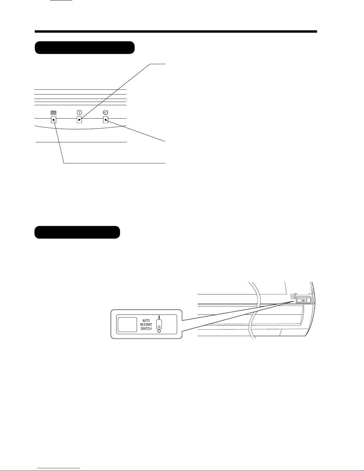
INDOOR UNIT INDICATORS
AUTO RESTART SWITCH
● In the event of power failure, the air conditioner will restart automatically in the previously selected mode
once the power is restored.
● In the event of power failure during TIMER operation, the timer will be reset and the unit will begin or stop
operating under a new timer setting.
OPERATION INDICATOR
● This fi gure shows the opening condition of
front panel. Refer to page 25 in relation to
how to open or close the front panel.
OPERATION LAMP
This lamp lights during operation.
The OPERATION LAMP fl ashes in the following cases
during heating.
(1) During preheating
For about 2–3 minutes after starting up.
(2) During defrosting
Defrosting will be performed about once an hour
when frost forms on the heat exchanger of the
outdoor unit, for 5–10 minutes each time.
TIMER LAMP
This lamp lights when the timer is working.
FILTER LAMP
When the device is operated for a total of about 200
hours, the FILTER lamp lights to indicate that it is time
to clean the fi lter. The lamp goes out when the POWER
SWITCH set to OFF and ON again.
HITACHI
– 11 –
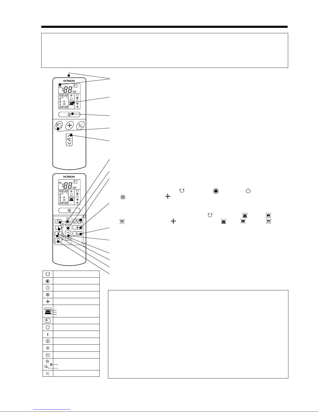
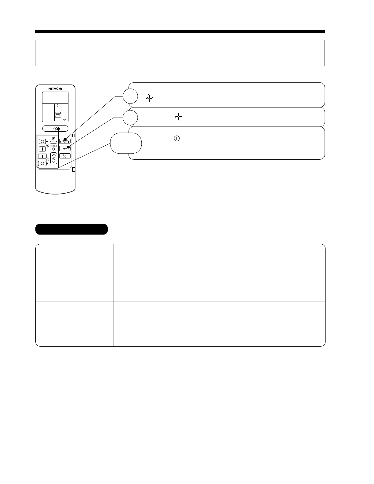
● Signal emitting window/transmission sign
Point this window toward the indoor unit when controlling it.
The transmission sign blinks when a signal is sent.
● Display
This indicates the room temperature selected, current time, timer status,
function and intensity of circulation selected.
● START/STOP button
Press this button to start operation. Press it again to stop operation.
● SLEEP button
Use this button to set the sleep timer.
● TEMPERATURE buttons
Use these buttons to raise or lower the temperature setting. (Keep pressed,
and the value will change more quickly.)
● TIME button
Use this button to set and check the time and date.
● RESET buttons
● FUNCTION selector
Use this button to select the operating mode. Every time you press it,
the mode will change from (AUTO) to (HEAT) to (DEHUMIDIFY)
to (COOL) and to (FAN) cyclically.
● FAN SPEED selector
This determines the fan speed. Every time you press this button, the
intensity of circulation will change from (AUTO) to (HI) to (MED)
to (LOW) (during the (FAN) mode, from HI to MED to LOW).
● AUTO SWING button
Controls the angle of the horizontal air defl ector.
● TIMER control
Use this button to set the timer.
● OFF-TIMER button Select the turn OFF time.
● ON-TIMER button Select the turn ON time.
● RESERVE button Time setting reservation.
● CANCEL button Cancel time reservation.
AUTO
HEAT
DEHUMIDIFY
COOL
FAN
FAN SPEED
LOW
MED
HI
SLEEPING
STOP (CANCEL)
START (RESERVE)
START/STOP
TIME
TIMER SET
TIMER SELECTOR
ON TIMER
OFF TIMER
AUTO SWING
NAMES AND FUNCTIONS OF REMOTE CONTROL UNIT
REMOTE CONTROLLER
This controls the operation of the indoor unit. The range of control is about 7 meters. If indoor lighting
is controlled electronically, the range of control may be shorter.
This unit can be fi xed on a wall using the fi xture provided. Before fi xing it, make sure the indoor unit
can be controlled from the remote controller.
Precautions for Use
● Do not put the remote controller in the following places.
● Under direct sunlight.
● In the vicinity of a heater.
● Handle the remote controller carefully. Do not drop it on the fl oor,
and protect it from water.
● Once the outdoor unit stops, it will not restart for about 3 minutes
(unless you turn the power switch off and on or unplug the power
cord and plug it in again).
This is to protect the device and does not indicate a failure.
● If you press the FUNCTION selector button during operation, the
device may stop for about 3 minutes for protection.
– 12 –
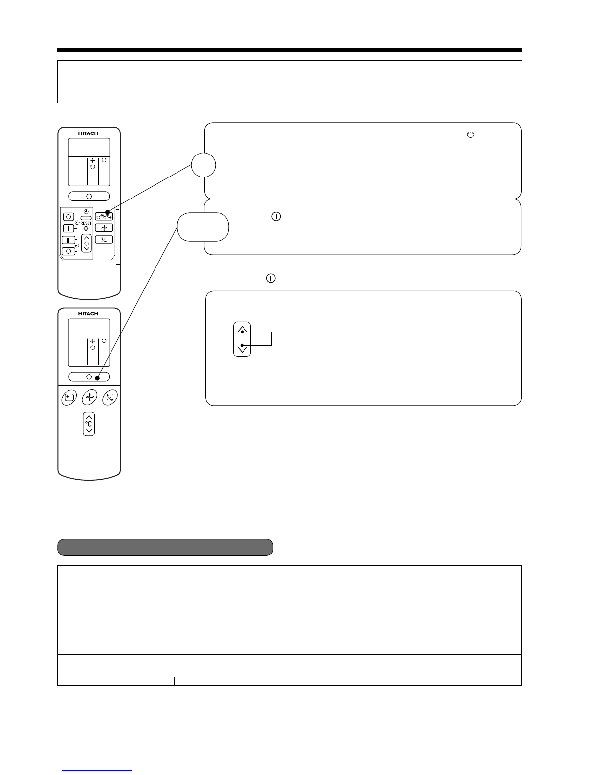
AUTOMATIC OPERATION
The device will automatically determine the mode of operation, HEAT, COOL or DEHUMIDIFY depending on
the initial room temperature. The selected mode of operation will not change when the room temperature varies.
■ As the settings are stored in memory in the remote controller, you only have
to press the (START/STOP) button next time.
Press the FUNCTION selector so that the display indicates the (AUTO)
mode of operation.
● When AUTO has been selected, the device will automatically determine
the mode of operation, HEAT, COOL or DEHUMIDIFY depending on
the initial room temperature.
Press the (START/STOP) button.
Operation starts with a beep.
Press the button again to stop operation.
You can raise or lower the temperature setting as necessary by maximum
of 3°C.
Press the temperature button and the temperature setting
will change by 1°C each time.
● The preset temperature and the actual room temperature may vary
somewhat depending on conditions.
● The display does not indicate the preset temperature in the AUTO mode.
If you change the setting, the indoor unit will produce a beep.
1
START
STOP
C
Over 27°C COOL
23~27°C
Under 23°C HEAT
Temperature settingFunction
27°C
23°C
Slightly lower than the
room temperature
LOW
FAN SPEED
HI at start, MED or LOW
after the preset temperature
is reached
HI at start, MED or LOW
after the preset temperature
is reached
-
-
DEHUMIDIFY
-
Initial room temperature
(approx.)
■ Condition of Automatic Operation
– 13 –
˚
C
˚
C
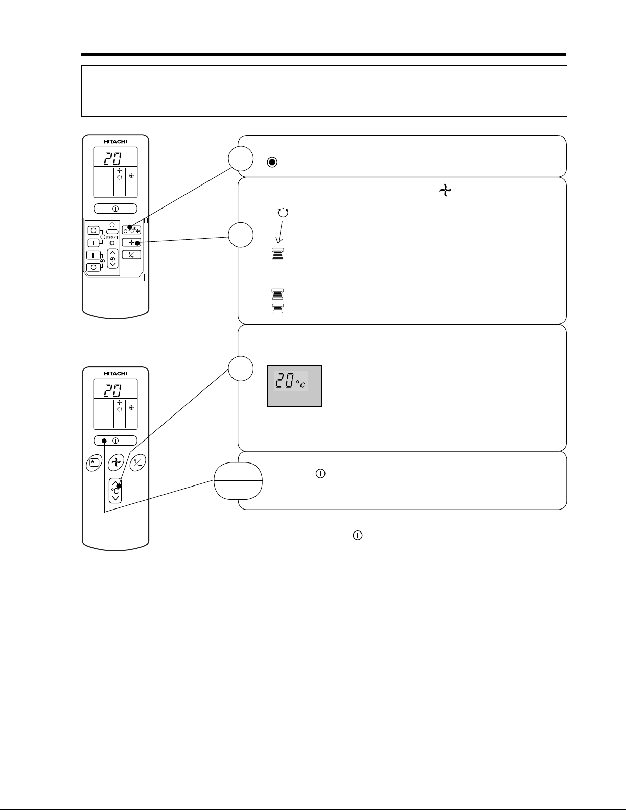
HEATING OPERATION
● Use the device for heating when the outdoor temperature is under 21°C.
When it is too warm (over 21°C), the heating function may not work in order to protect the device.
● In order to keep reliability of the device, please use this device above –10°C of the outdoor temperature.
Press the FUNCTION selector so that the display indicates
(HEAT).
Set the desired FAN SPEED with the (FAN SPEED) button
(the display indicates the setting).
(AUTO) : The fan speed is HI at fi rst and varies to MED
automatically when the preset temperature has
been reached.
(HI) : Economical as the room will become warm
quickly.
But you may feel a chill at the beginning.
(MED) : Quiet.
(LOW) : More quiet.
Set the desired room temperature with the TEMPERATURE
buttons (the display indicates the setting).
The range of 18-22°C is recommended as the
room temperature for heating.
If the temperature setting is 20°C, the room
temperature will be controlled at around 20°C.
The temperature setting and the actual room temperature may
vary somewhat depending on conditions.
Press the (START/STOP) button. Heating operation starts
with a beep. Press the button again to stop operation.
■ As the settings are stored in memory in the remote controller, you
only have to press the (START/STOP) button next time.
1
2
3
START
STOP
– 14 –
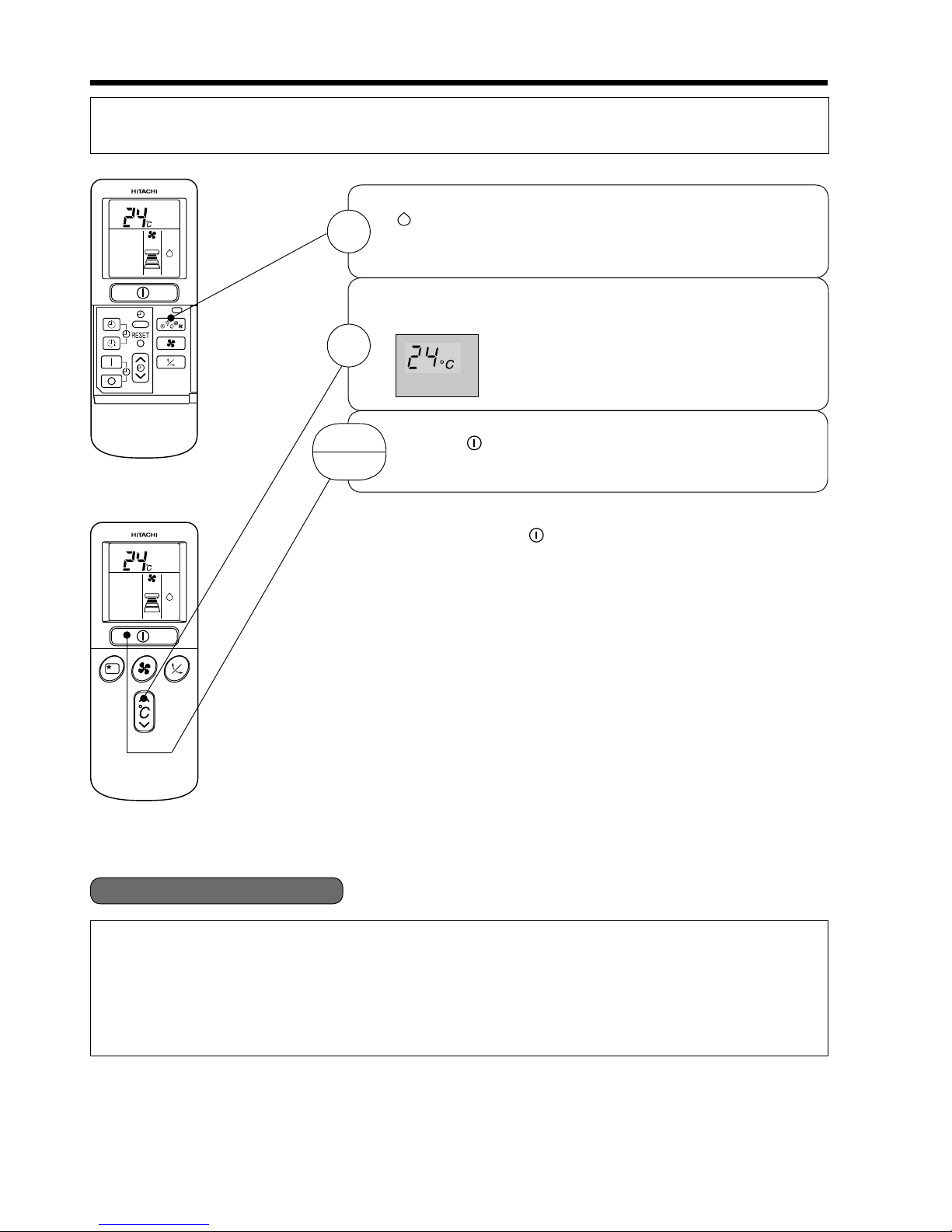
DEHUMIDIFYING OPERATION
Use the device for dehumidifying when the room temperature is over 16°C.
When it is under 15°C, the dehumidifying function will not work.
■ Dehumidifying Function
When the room temperature is higher than the temperature setting: The device will dehumidify the room,
reducing the room temperature to the preset level.
When the room temperature is lower than the temperature setting: Dehumidifying will be performed at
the temperature setting slightly lower than the current room temperature, regardless of the temperature
setting. The function will stop (the indoor unit will stop emitting air) as soon as the room temperature
becomes lower than the setting temperature.
Set the desired room temperature with the TEMPERATURE
button (the display indicates the setting).
The range of 20-26˚C is recommended as
the room temperature for dehumidifying.
Press the (START/STOP) button. Dehumidifying operation
starts with a beep. Press the button again to stop operation.
2
■ As the settings are stored in memory in the remote controller, you
only have to press the (START/STOP) button next time.
START
STOP
Press the FUNCTION selector so that the display indicates
(DEHUMIDIFY).
The FAN SPEED is set at LOW automatically.
The FAN SPEED button does not work.
1

– 15 –
˚
C
˚
C
COOLING OPERATION
Use the device for cooling when the outdoor temperature is 22-42°C.
If indoor humidity is very high (over 80%), some dew may form on the air outlet grille of the indoor unit.
■ As the settings are stored in memory in the remote controller, you
only have to press the (START/STOP) button next time.
1
2
3
START
STOP
Press the FUNCTION selector so that the display indicates
(COOL).
Set the desired FAN SPEED with the (FAN SPEED) button
(the display indicates the setting).
(AUTO) : The FAN SPEED is HI at fi rst and varies to
MED automatically when the preset temperature
has been reached.
(HI) : Economical as the room will become cool quickly.
(MED) : Quiet.
(LOW) : More quiet.
Set the desired room temperature with the TEMPERATURE
button (the display indicates the setting).
The range of 25-28°C is recommended as the
room temperature for cooling.
If the temperature setting is 27°C, the room
temperature will be controlled at around 27°C.
The temperature setting and the actual room temperature may
vary some how depending on conditions.
Press the
(START/STOP) button. Cooling operation starts
with a beep. Press the button again to stop operation. The
cooling function does not start if the temperature setting is
higher than the current room temperature (even though the
(OPERATION) lamp lights). The cooling function will start
as soon as you set the temperature below the current room
temperature.
– 16 –
Press the FUNCTION selector so that the display indicates
(FAN).
Press the (FAN SPEED) button.*
Press the (START/STOP) button. Fan operation starts with
a beep. Press the button again to stop operation.
FAN SPEED (AUTO)
.....
When the AUTO fan speed mode is set in the cooling/heating operation:
For the heating operation
● The fan speed will automatically change according to the temperature
of discharged air.
● When the difference of room temperature and setting temperature is
large, fan starts to run at HI speed.
● When the room temperature reaches setting temperature, fan speed
changes to LOW automatically.
● When the difference of room temperature and setting temperature is
large, fan starts to run at HI speed.
● After room temperature reaches the preset temperature, the cooling
operation, which changes the fan speed and room temperature to obtain
optimum conditions for natural healthful cooling will be performed.
For the cooling operation
FAN OPERATION
You can use the device simply as an air circulator. Use this function to dry the interior of the indoor
unit at the end of summer.
1
2
START
STOP
– 17 –
H
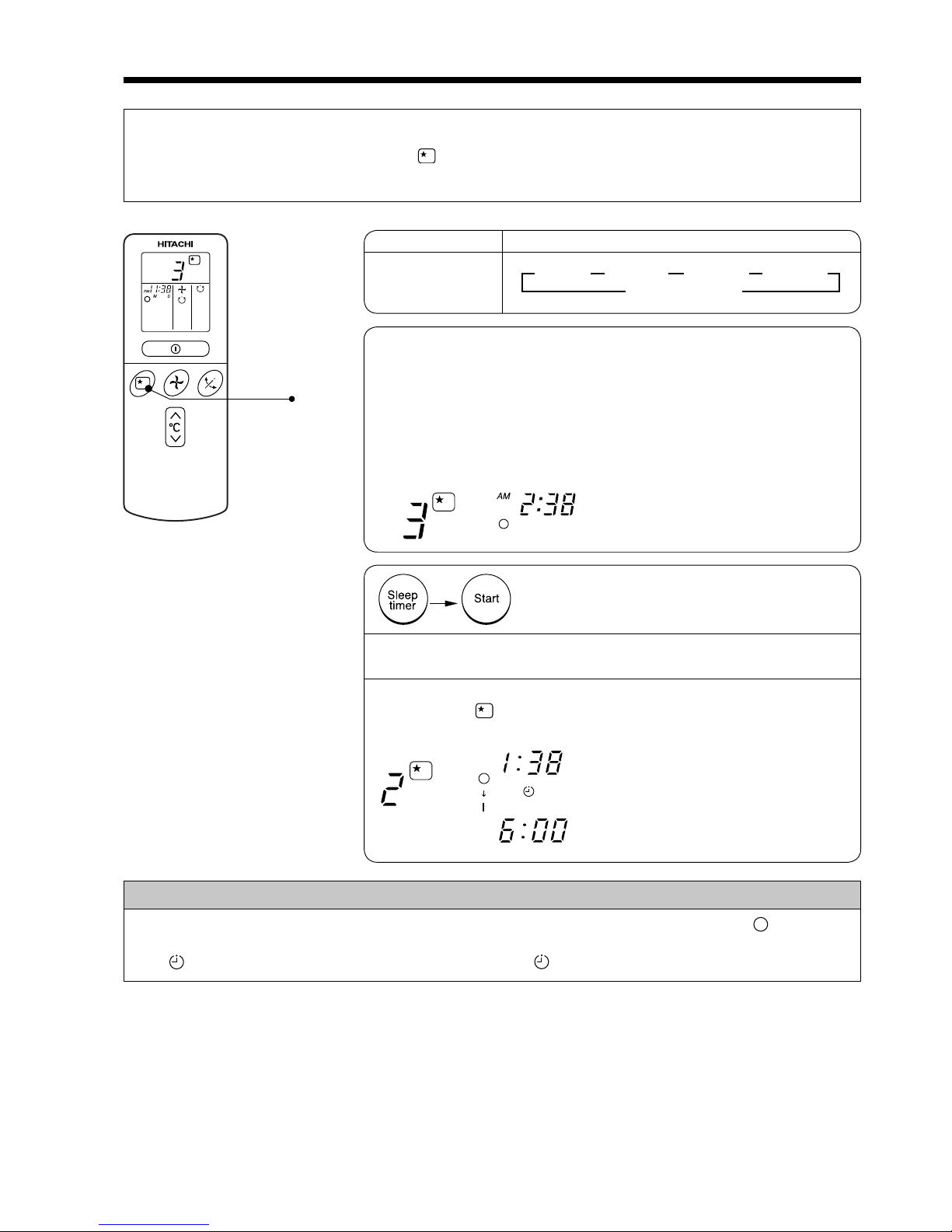
HOW TO SET THE SLEEP TIMER
1 Set the ON-timer.
Set the current time at fi rst if it is not set before (see the pages for setting
the current time). Press the (SLEEP) button, and the display changes
as shown below.
Mode
Sleep timer
Indication
1 hour 2 hours 3 hours 7 hours
Sleep timer off
44 44
1
Sleep Timer: The device will continue working for the designated
number of hours and then turn off.
Point the signal window of the remote controller toward the indoor
unit, and press the SLEEP button.
The timer information will be displayed on the remote controller.
The TIMER lamp lights with a beep from the indoor unit. When the
sleep timer has been set, the display indicates the turn-off time.
Example: If you set 3 hours sleep
time at 11:38 p.m., the turn-off
time is 2:38 a.m.
2 Press the (SLEEP) button and set the sleep timer.
The device will be turned off by the sleep
timer and turned on by on-timer.
How to Cancel Reservation
Point the signal window of the remote controller toward the indoor unit, and press the (CANCEL)
button.
The (RESERVED) sign goes out with a beep and the (TIMER) lamp turns off on the indoor unit.
For heating:
In this case, the device will turn
off in 2 hours (at 1:38 a.m.) and
turn on early so that the preset
temperature will be almost reached
at 6:00 next morning.
SLEEP
H
H
AM
AM
– 18 –
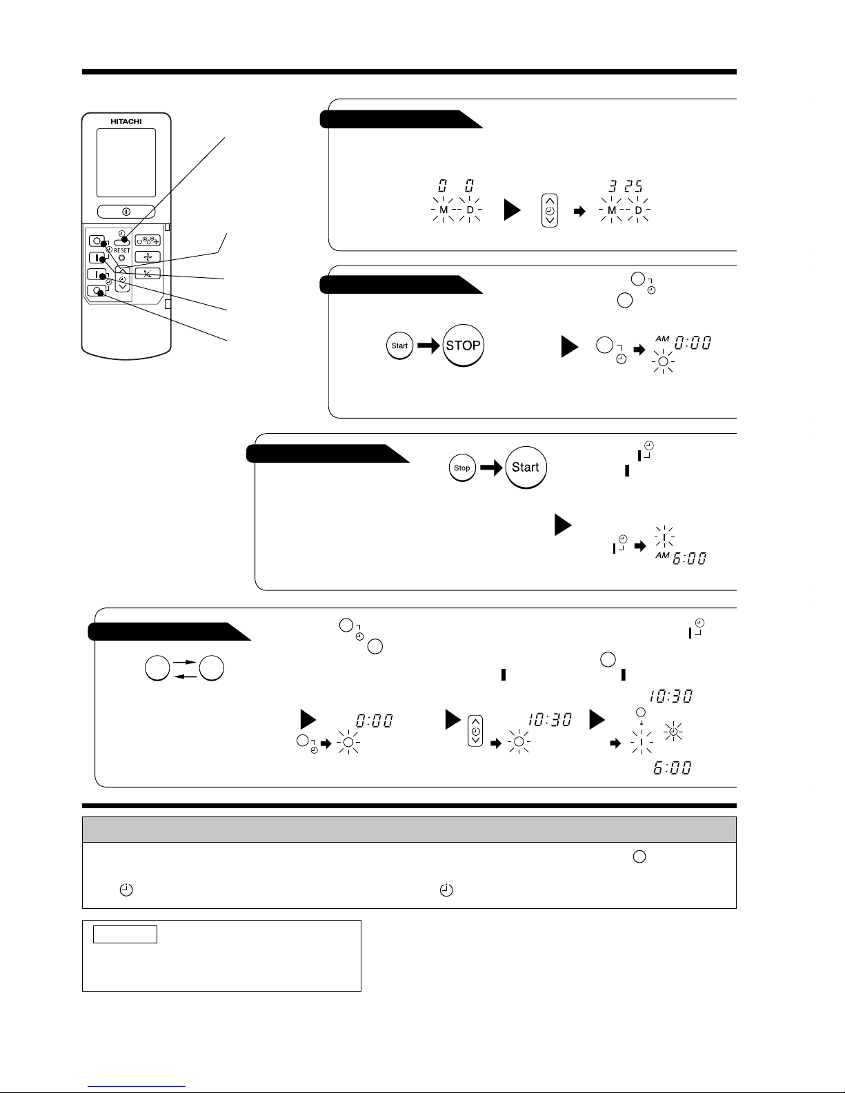
1 Press the (OFF-TIMER)
button. The (OFF) mark blinks
on the display.
HOW TO SET THE TIMER
ON/OFF-Timer
OFF-Timer
You can set the device to turn off
at the present time.
After you change the
batteries;
How to Cancel Reservation
Point the signal window of the remote controller toward the indoor unit, and press the (CANCEL)
button.
The (RESERVED) sign goes out with a beep and the (TIMER) lamp turns off on the indoor unit.
1 Set the current month and
day with the TIMER control
button.
NOTE
You can set only one of the OFF-timer,
ON-timer and ON/OFF-timer.
ON-Timer
Time, Day, Month
● The device will turn on
at the designated times.
TIME, DAY,
MONTH
(current time,
day, month)
OFF TIMER
ON TIMER
RESERVE
CANCEL
PM
Start Stop
PM
AM
PM
1 Press the (ON-TIMER)
button the (ON) mark blinks
on the display.
1 Press the (ON-OFF)
button so that the (OFF)
mark blinks.
2 Set the turn-off time
with the TIMER control
button.
Press the (RESERVE)
button.
3 Press the (ON-
TIMER) button so that the
(OFF) mark lights and
the (ON) mark blinks.
● The device will turn on (off) and off
(on) at the designated times.
● The switching occurs fi rst at the
preset time that comes earlier.
● The arrow mark appearing on the
display indicates the sequence of
switching operations.
 Loading...