

Hitachi RAS-18G4, RAC-18G4 Installation Manual
above 50mm
above 100mm
above
0.45m
above 300mm
must not bend
above 100mm
2,300mm or more
1
2
4
5
3
Maximum pipe length 15m
Minimum pipe length 5m
above 200mm
above 700mm
above 200mm
above 50mm when
installed on the
ceiling of balcony
(
)
above 100mm
above 100mm
give clearance as
wide as possible
Plug
7
SPLIT UNIT AIR CONDITIONER
INSTALLATION MANUAL
Indoor Unit Outdoor Unit
RAS-18G4 RAC-18G4
●
+
– Screwdriver ●Measuring Tape●Knife
●
Saw●ø 65mm Power Drill●Hexagonal Wrench
Key ( 4mm)
●
Wrench (14, 17, 24mm)●Gas
Leakage Detector
●
Pipe Cutter●Putty●Vinyl
Tape
●
Pliers●Flare Tool
●
Carefully read through the procedures of proper
installation before starting installation work.
●
The sales agent should inform customers regarding
the correct operation of installation.
Tools Needed For Installation Work
SAFETY PRECAUTION
●
Read the safety precautions carefully before operating the unit.
●
The contents of this section are vital to ensure safety. Please pay special attention to the following sign.
WARNING ........ Incorrect methods of installation may cause death or serious injury.
CAUTION ......... Improper installation may result in serious consequence.
Be sure that the unit operates in proper condition after installation. Explain to customer the proper way of operating
the unit as described in the user’s guide.
!
!
WARNING
!
CAUTION
!
●
A circuit breaker or fuse (30A time delay) must be installed. Without a circuit breaker or fuse the danger of electric shock
exists.
A main switch with a contact gap of more than 3mm has to be installed in the power supply line to the outdoor unit.
●
Do not install the unit near a location where there is flammable gas. The outdoor unit may
catch fire if flammable gas leaks around it.
●
Please ensure smooth flow of water when installing the drain hose.
●
Piping shall be suitable supported with a maximum spacing of 1m between the supports.
●
Please request your sales agent or qualified technician to install your unit. Water leakage, short circuit or fire may occur if you
do the installation work yourself.
●
Please observe the instructions stated in the installation manual during the process of installation. Improper installation may
cause water leakage, electric shock and fire.
●
Make sure that the units are mounted at locations which are able to provide full support to the weight of the units. If not, the
units may collapse and impose danger.
●
Observe the rules and regulations of the electrical installation and the methods described in the installation manual when
dealing with the electrical work. Use power cables approved by the authorities of your country.
●
Be sure to use the specified wire for connecting the indoor and outdoor units. Please ensure that the connections are tight
after the conductors of the wire are inserted into the terminals. Improper insertion and loose contact may cause over-heating
and fire.
●
Please use the specified components for installation work. Otherwise, the units may collapse or water leakage, electric shock
and fire may occur.
●
Be sure to use the specified piping set for R410A. Otherwise, this may result in broken copper pipes or faults.
●
When installing or removing an air conditioner, only specified refrigerant (R410A) shall be allowed, do not allow air or moisture
to remain in the refrigeration cycle. Otherwise, pressure in the refrigeration cycle may become abnormally high so that a
rupture may be caused.
●
Be sure to ventilate fully if a refrigerant gas leak while at work. If the refrigerant gas comes into contact with fire, a poisonous
gas may occur.
●
After completion of installation work, check to make sure that there is no refrigeration gas leakage. If the refrigerant gas leaks
into the room, coming into contact with fire in the fan-driven heater, space heater, etc., a poisonous gas may occur.
●
Unauthorized modifications to the air conditioner may be dangerous. If a breakdown occurs please call a qualified air conditioner
technician or electrician. Improper repairs may result in water leakage, electric shock and fire, etc.
FOR SERVICE PERSONNEL ONLY
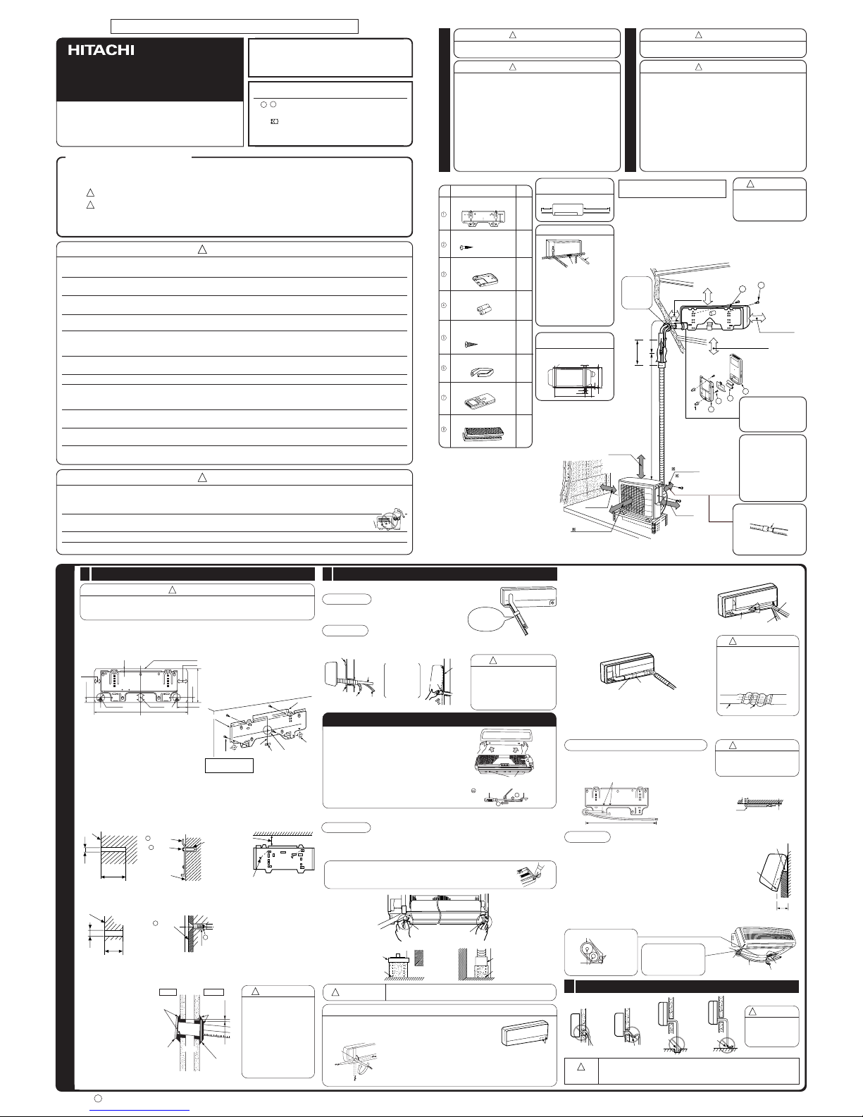
THE CHOICE OF MOUNTING SITE (Please note the following matters and obtain permission from customer before installation).
WARNING
!
●
The unit should be mounted at stable, non-vibratory location which
can provide full support to the unit.
WARNING
!
●
The Outdoor unit must be mounted at a location which can support heavy weight. Otherwise, noise and vibration will increase.
CAUTION
!
●
No nearby heat source and no obstruction near the air outlet is
allowed.
●
The clearance distances from top, right and left are specified in
figure below.
●
The location must be convenient for water drainage and pipe
connection with the Outdoor unit.
●
To avoid interference from noise please place the unit and its
remote controller at least 1m from the radio, television and inverter
type fluorescent lamp.
●
To avoid any error in signal transmission from the remote controller,
please put the controller far away from high-frequency machines
and high-power wireless systems.
●
The installation height of indoor unit must be 2.3m or more in a
non public area.
CAUTION
!
●
Do not expose the unit under direct sunshine or rain. Besides, ventilation
must be good and clear of obstruction.
●
The air blown out of the unit should not point directly to animals or plants.
●
The clearances of the unit from top, left, right and front are specified in
figure below. At least 3 of the above sides must be open air.
●
Be sure that the hot air blown out of the unit and noise do not disturb the
neighbourhood.
●
Do not install at a location where there is flammable gas, steam, oil and
smoke.
●
The location must be convenient for water drainage.
●
Place the Outdoor unit and its connecting cord at least 1m away from the
antenna or signal line of television, radio or telephone. This is to avoid
noise interference.
●
Do not install outdoor unit facing strong wind direction. It may damage the
fan motor.
INDOOR UNIT
Names of Indoor Components
Hanger
QtyNo. Item
The Length of Indoor Unit
Connecting Cord
Figure showing the Installation
of Indoor and Outdoor Unit.
OUTDOOR UNIT
1
1
Screw for holder of
Remote Controller
(3.1x16)
AAA Size Battery
Direction of Piping
Dimension of Mounting Stand
of the Outdoor unit
(unit : mm)
Holder for Remote
Controller
There are 4 directions
allowed, namely, horizontally
perpendicular to the unit,
vertically down from right,
horizontally out from right and
horizontally out to left.
Don’t form the piping
downward at the left of the unit.
(4.1x32)
Remote Controller
Purifying Filter
2
6
3
1
4
2
5
2
6
7
8
1
1
● The difference in height
between the indoor and
outdoor unit should be
kept max 5m.
● The connecting pipe, no
matter big or small,
should all be insulated
with insulation pipe and
then wrapped with vinyl
tape. (The insulator will
deteriorate if it is not
wrapped with tape).
The connection of insulated
drain hose.
Please use insulated drain
hose for the indoor piping
(commercial product).
The indoor piping should be
insulated with the enclosed
insulation pipe. (If the
insulator is insufficient,
please use commersial
products).
inner diameter ø 16mm
Be sure to
completely
seal any
gap with
putty.
Insulation pipe
1
Screw for Hanger
0.9m
1.6m
Connection
Horizontally
perpendicular
to the unit
57
12
35
120
500
320
10
35
(10)
340
mounting stand
!
CAUTION
•
The installation height
of indoor unit must be
2.3m or more in a non
public area.
Installation of Hanger, Wall Penetration and Installation of Protection Pipe
1
CAUTION
!
●
The draining of the water container inside the indoor unit can be done from the left.
Therefore the hanger must be fixed horizontally or slightly tilted towards the side of
drain hose. Otherwise, condensed water may overflow the water container.
Direct Mounting On The Wall
●
Please use hidden beams in the wall to hold the hanger.
Wall Penetration and Installation of Protection Pipe
●
Drill a ø 65mm hole on
wall which is slightly tilted
towards the outdoor side.
Drill the wall at a small
angle.
●
Cut the protection pipe
according to the wall
thickness.
●
Empty gap in the sleeve
of protection pipe should
be completely sealed
with putty to avoid
dripping of rain water into
the room.
Procedures of Installation and Precautions
●
Procedures to fix the hanger.
1.Drill holes on wall. 2. Push plug into the holes. 3. Fix the hanger on wall
(As shown below) (As shown below) with 4.1 x 32 screw
(As shown in figure below)
●
Procedures to fix the holder of remote control.
1.Drill holes on wall. 2. Push plug into the holes.
(As shown below) (As shown below)
Installation of the Indoor Unit
2
VERTICALLY DOWNWARD PIPING
Preparation
●
Connect connecting cord.
●
Pull out the pipe, connecting cord and drain hose.
Installation
●
The upper part of the Indoor unit is hanged on the hanger.
●
The projection at the lower part of the Indoor unit is hooked onto the hanger.
Please pull the lower part of
the Indoor unit outwards to
check if the unit is hooked
onto the hanger. Improper
installation may cause
vibration and noise.
!
CAUTION
HORIZONTAL PIPING
Preparation
Change of Drain Hose and Installation Procedures.
●
Exchange the location of drain hose and drain cap during horizontal piping as shown in
figure below. Be sure to plug in the drain hose until the insulating material folds upon itself.
●
Please use pliers to pull out the drain cap.
(This is an easier way to remove the drain cap).
INSTALLATION OF REFRIGERATING PIPES AFTER CONNECTION
●
The refrigerating pipes should be adjusted to fit into
the hole on the wall and then ready for further
connection.
●
The terminals of 2 connected pipes must be covered
with insulator used for terminal connection. Then the
pipes are wrapped with insulation pipe.
●
Connect the connecting cord after removing electrical
cover. (Refer to “CONNECTION OF POWER CORD”)
●
After adjustment, fit the connecting cord and pipes
into the space available under the indoor unit. Use
holder to hold them tight.
!
CAUTION
●
The rubber strap used for
fixing the insulator should
not be tied with great force.
Otherwise, this will damage
heat insulation and causes
water condensation.
●
Holder can be attached at the either of 2 places.
Please select the easier position.
THE CONNECTION OF REFRIGERATING PIPE DURING THE
INSTALLATION OF INDOOR UNIT
Preparation To Install Refrigerating Pipes
!
CAUTION
●
Please fix in the plastic core
after flaring to avoid plastic
chips entering the pipes.
CAUTION
!
You are free to choose the side (left or right) for the installation of drain
hose. Please ensure the smooth flow of condensed water of the Indoor
unit during installation. (Carelessness may result in water leakage.)
!
CAUTION
Be sure that the
drain hose is not
loosely connected
or bend.
Be sure that the wire is not
in contact with any metal
in the wall. Please use the
protection pipe as wire
passing through the hollow
part of the wall so as to
prevent the possibility of
damaged by mouse.
Unless it seals completely,
any air with high humidity
flows from outdoor and
any dew may drop.
!
WARNING
●
The refrigerating pipes and connecting cord
transform and are attached.
●
The end of the refrigerating pipes are at locations
marked with “
” symbol.
Installation of Drain Hose
3
Installation
Hang the Indoor unit onto the hanger. Use the temporary stand
at the back of the Indoor unit to push its lower part 15cm
forwards.
●
Place the drain hose through the hole on the wall.
●
Wrap the refrigerating pipes with insulation pipe after
connecting refrigerating pipe.
●
Connect the connecting cord after removing electrical cover.
(Refer to “Connection of Power Cord”)
●
After adjustment, the connecting cord and refrigerating pipes
are placed into the space available under the Indoor unit.
●
The projection of Indoor unit must hook to the hanger.
INDOOR UNIT
<
I555: A
>
External dimension of
indoor unit
180mm
180mm
80mm
1030mm
ø 65mm
200mm
45mm
30mm
Drain Hose
45mm
298mm
Level
Line
Hole for
pipe
Mark
Weight
Screw for Hanger
Please use more
than 4 screws.
Hanger
32mm
20mm
ø4.8mm
ø4.4mm
Wall
1 Hanger
2 Screw
Plug
Wall
above 50mm
Ceiling
4.1 x 32 Screw
Wall
Remote
Control
Holder
5 Screw
Plug
3
HOW TO REMOVE INDOOR UNIT FROM HANGER
●
Pull down PULL section on the bottom of indoor
unit and pull it towards you, then claws are
released from hanger. (Indicated by 2 arrows in
the drawing on the right.)
●
When bottom face of indoor unit cannot be
pulled due to obstacles, etc. Remove front cover,
insert screw driver into circle hole, pull claws
down and pull indoor unit towards you.
●
Please check how to remove and attach front
cover in this instruction manual.
Sleeve of
protection
pipe
WALL
Protection
pipe
Seal with
putty
Seal with
putty
2 ~ 5mm
OutdoorIndoor
Connecting cords,
pipe and drain hose
must be tied together
with Vinyl tape.
Hanger
Hook
Refrigerating
Pipe
Connecting
Cord
Drain Hose
Protection
Pipe
Lift the body
of the unit
upwards and
then force
it downwards.
Hanger
Projection
Screw driver
Claw of indoor unit
Circle hole
2
1
!
CAUTION
Condensed water may leak out if not inserted properly.
HORIZONTAL & DOWNWARD PIPING – MAKING OPENINGS
●
During horizontal or downward piping, use a knife to cut
openings as shown in figure. Then smoothen the edges of
openings with a file.
●
Turn the piping while holding down the lower
portion of pipe-support by hand.
Drain hoseDrain cap
Drain cap
Please insert
until here
Drain hose
Please insert
until here
Pipe
support
Pull up the pipe after
bending downward
Openings
Pipe
Connecting cord
Drain hose
Insulation pipe (must be wrapped with
vinyl tape at every 120mm).
Holder
Pipe
Rubber strap tied with great force
below
5mm
Please bend at a small
radius to form an arc
0.65m
about 15cm
Projection
Temporary stand
Connected
section
Holder
Connecting cord
Drain hose
Protection
pipe
Heat insulation pipe
Connecting
cord
Refrigerating pipe
Pull this to the front
during the connection
of refrigerating pipes
to ease task.
Bending
upwards
Condensed
water pond
Ditch
Condensed
water pond
OUTDOOR UNIT
●
Please mount the Outdoor unit on stable ground to prevent vibration
and increase of noise level.
●
Decide the location for piping after sorting out the different types of
pipe available.
●
When removing side cover, please pull the handle after undoing the
hook by pulling it downward.
Removal Of Air From The Pipe And Gas Leakage Inspection
Gas Leakage Inspection
Please use gas leakage detector to check if leakage
occurs at the connection of Flare nut as shown on
the right.
If gas leakage occurs, further tighten the connection
to stop leakage. (Use the detector provided for
R410A)
FINAL STAGE OF INSTALLATION
Insulation And Maintenance Of Pipe Connection
1
●
The connected terminals should be completely sealed with
heat insulator and then tied up with rubber strap.
●
Please tie the pipe and power line together with vinyl tape as
shown in the figure showing the installation of Indoor and
Outdoor units. Then fix their position with holders.
●
To enchance the heat insulation and to prevent water
condensation, please cover the outdoor part of the drain hose
and pipe with insulation pipe.
●
Completely seal any gap with putty.
Installation Of Remote Controller
2
Power Source And Operation Test
3
●
The remote controller can be placed in its holder which is
fixed on wall or beam.
●
To operate the remote controller at its holder, please ensure
that the unit can receive signal transmitted from the controller
at the place where the holder is to be fixed. The unit will beep
when signal is received from the remote controller. The signal
transmission is weaken by the fluorescent light. Therefore,
during the installation of the remote control holder, please
switch on the light, even during day time, to determine the
mounting location of the holder.
Power Source
CAUTION
!
●
Please use a new socket. Accident may occur due to the use of old
socket because of poor contact.
●
Please plug in and then remove the plug for 2 – 3 times. This is to
ensure that the plug is completely plugged into the socket.
●
Keep additional length for the power cord and do not render the
plug under external force as this may cause poor contact.
●
Do not fix the power cord with U-shape nail.
Operation Test
●
Please ensure that the air conditioner is in normal
operating condition during the operation test.
●
Explain to your customer the proper operation
procedures as described in the user’s manual.
<
I555: A
>
The controller must
be hooked onto the
hook at the lower
part of the holder.
Push in the remote
controller in the
direction as shown
in figure below.
3
Procedures of using Vacuum Pump for Air Removal
As shown in right figure, remove the cap
of valve core. Then, connect the charge
hose. Remove the cap of valve head.
Connect the vacuum pump adapter to
the vacuum pump and connect the
charge hose to the adapter.
Fully tighten the “Hi” shuttle of the
manifold valve and completely unscrew
the “Lo” shuttle. Run the vacuum pump
for about 10–15 minutes, then completely
tighten the “Lo” shuttle and switch off
the vacuum pump.
2
Completely unscrew the spindle of the
service valve (at 2 places) in anticlockwise direction to allow the flow of
coolant (using Hexagonal Wrench key).
3
Remove the charge hose and tighten the
cap of valve head. Check the cap’s
periphery if there is any gas leakage.
The task is then completed.
4
1
Preparation of Pipe
●
Use a pipe cutter to cut the copper pipe.
●
Jagged edge will cause leakage.
●
Point the side to be trimmed downwards during trimming to prevent copper
chips from entering the pipe.
●
Before flaring, please put on the flare nut.
Pipe Connection
2
INSTALLATION OF REFRIGERATING PIPES AND AIR REMOVAL
CAUTION
!
Outer
Diameter (mm)
6.35
9.52
12.7
Imperial flaring tool
0.0
~
0.5mm
0.0
~
0.5mm
0.0
~
0.5mm
Rigid flaring tool
A (mm)
AIR REMOVAL
WARNING
●
If you cannot attach the side cover due to the connecting cord, press
the connecting cord in direction to the front panel to fix it.
●
Be sure that the hooks of the side cover is fixed in certainly. Otherwise
water leakage may occur and this causes short circuit or faults.
●
The connecting cord should not touch to service valve and pipes. (It
becomes high temperature in heating operation.)
●
The naked part of the wire core should be 10 mm and fix it to the terminal tightly. Then try to pull the
individual wire to check if the contact is tight. Improper insertion may burn the terminal.
●
Be sure to use only power cables approved from the authorities in your country. For example in Germany:
Cable type: NYM 3x1.5mm
2
, (fuse = 20A time delay)
●
Please refer to the installation manual for wire connection to the terminals of the units. The cabling must
meet the standards of electrical installation.
●
There is a AC voltage of 240V between the L and N terminals. Therefore, before servicing, be sure to
remove the plug from the AC outlet or switch off the main switch.
Checking for the electric source and
the voltage range
●
Before installation, the power source must be checked and necessary
wiring work must be completed. To make the wiring capacity proper, use
the wire gauges list below for the lead-in from a pole transformer and for
the wiring from a switch board of fuse box to the main switch and outdoor
unit in consideration of the locked rotor current.
●
Investigate the power supply capacity and other electrical conditions at
the installation location.
Depending on the model of room air conditioner to be installed, request
the customer to make arrangements for the necessary electrical work
etc.
The electrical work includes the wiring work up the outdoor. In localities
where electrical conditions are poor, use of a voltage regulation is
recommended.
IMPORTANT
Cable length
up to 16m
up to 15m
up to 25m
Wire cross-section
1.5mm
2
2.5mm
2
4.0mm
2
IMPORTANT
●
THIS APPLIANCE MUST BE EARTHED.
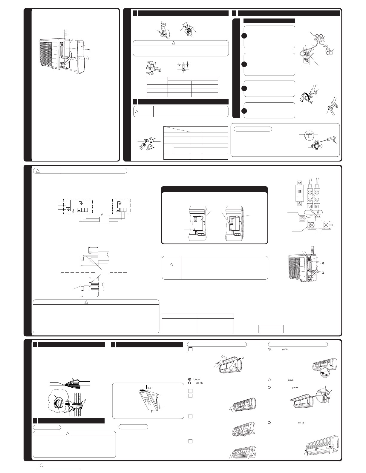
Procedures of Wiring
Wiring of The Outdoor Unit
●
Please remove the side cover for wire connection.
!
WARNING
!
CONNECTION OF POWER CORD
●
Please be careful when bending the copper pipe.
●
Screw in manually while adjusting the center. After that, use of torque wrench to
tighten the connection.
WARNING
!
In case that power is supplied from Indoor Unit
How to Remove The Front Cover
Please face this side (suction
side) of the unit to the wall.
Please remove side cover
when connecting the piping
and connecting cord.
Pull downward
●
Recommend to use
R410A flaring tool.
CAUTION
!
In case of removing flare nut of an Indoor unit, first remove a nut
of small diameter side, or a seal cap of big diameter side will fly
out. Prevent water from entering into the piping when working.
When the meter reaches - 101KPa
(-76cmHg) during pumping, fully
tighten the shuttle.
Meter showing pressure
Closed
R410A
Manifold valve
Vacuum
pump
Valve
Charge hose
Valve
Vacuum pump
adapter
When pumping starts, slightly loosen the
flare nut to check of air sucked in. Then
tighten the flare nut.
Power line
Indoor
Unit
Outdoor
Unit
GRN + YEL
GRN + YEL
Strip wires
Fuse Capacity
20A time delay fuse
Connect the
earth cord
After remove the
screw and band,
and put the
connecting cords
and fix the band
with screw.
Earth terminal
B
A
1 Remove the front panel.
●
Please remove and attach the front panel by both hands.
●
After opening the front panel by both hands.
11
11
1
Undo the right arm while pushing it inside.
22
22
2
Slide the front panel to right as shown in figure. Then
remove while pulling it to front.
2 Remove the filters.
3 Remove the caps and screws at the lower portion of the
front cover.
4 Pull the front cover upward as far as the location where
the lower portion of the front cover is on the deflector.
5 Remove while pulling the front cover in direction to arrow
as shown in figure to hold the both sides of front cover.
Cap
Screw
Lower portion of front cover
Deflector
How to Attach the Front Cover
11
11
1
After covering the front cover to the unit, certainly hook at
the upper portion (three places). Then, check that the drain
pan is certainly attached. Push the center of front cover in
the direction of arrow.
22
22
2
Fix the front cover at lower portion by screws and attach
the caps.
33
33
3
Attach the front panel.
●
Certainly insert the left shaft of the front panel to the hole
of the front cover. Next insert the right shaft as same as
the left.
44
44
4
Attach the filters which are placed the surface written
“FRONT” up.
●
After attaching the filters, push the front panel at three
arrow portion as shown in figure and close it.
Hole
Guide
Shaft
Copper pipe
Trimming tool
A
Die
Die
Copper pipe
1.0mm
1.0mm
1.0mm
Wrench
Torque
wrench
Flare nut
Lo Hi
The body of
service valve
Cap of
valve core
Hexagonal
Wrench Key
Cap of valve head
Cap of valve head
L
N
BABA
Indoor Unit
Line Cord
AC 220-240V
Outdoor Unit
Connecting Cord
2.0
25mm
30mm
10mm
10mm
70mm
10mm
10mm
35mm
Sleeve of
protection pipe
Putty
Putty
Insulation material for pipe connection
Remote
Controller
Holder for
Remote Controller
Screw (2 pieces)
1
2
Wiring Of The Indoor Unit
●
For wire connection of the Indoor unit, you need to remove front panel and electrical cover.
Method to remove front panel
●
Refer to “FINAL STAGE OF INSTALLATION – How to Remove The Front Cover”.
Method to remove electrical cover
●
Remove the screw and electrical cover.
●
Insert the connecting cord (A, B) from the bottom of unit.
●
Fixed the wire to terminal wires firmly as shown in figure at right side.
AUTO
RESTART
SWITCH
AUTO
RESTART
SWITCH
Screw
Electrical cover
Screw
A
ON
OFF
B
1
Outer
dia.of pipe
6.35 (1/4")
9.52 (3/8")
12.7 (1/2")
6.35 (1/4")
9.52 (3/8")
12.7 (1/2")
Valve
head cap
Torque N·m
(kgf · cm)
13.7 – 18.6 (140 – 190)
34.3 – 44.1 (350 – 450)
44.1 – 53.9 (450 – 550)
19.6 – 24.5 (200 ~ 250)
19.6 – 24.5 (200 ~ 250)
29.4 – 34.3 (300 – 350)
12.3 – 15.7 (125 ~ 160)
Small dia. side
Large dia. side
Valve core cap
Small dia. side
Large dia. side

●
Ein Stromauslöser oder eine Sicherung (30A zeitverzögert) müssen installiert werden. Andernfalls besteht die Gefahr eines
Stromschlags.
In die Stromzuleitung zum Außengerät muß ein Hauptschalter mit einem Kontaktabstand von mehr als 3.5 mm
eingebaut werden.
●
Montieren Sie das Gerät nicht in der Nähe von brennbarem Gas. Das Außengerät könnte
Feuer fangen, wenn brennbares Gas in seiner Umgebung entweicht.
●
Achten Sie daraf, Daß eine einwandfreie Wasserableitung möglich ist.
●
Die Rohrleitungen sind gut abzustützen, wobei der Zwischenraum zwischen den Stützen nicht mehr als 1 m betragen soll.
INNENGERÄT
Erforderliche Werkzeuge
Vorsichtsmaßnahmen
●
Bitte lesen Sie die Vorsichtmaßnahmen sorgfältig durch vor Inbetriebnahme des Gerätes.
●
Für die Sicherheit ist der Inhalt dieses Abschnittes von vitaler Wichtigkeit. Bitte beachten Sie in besonderem Maße
folgendes Zeichen.
WARNUNG .......... Inkorrekte Methoden des Einbaus könnten Tod oder ernste Verletzungen zur Folge haben.
VORSICHT .......... Ungeeigneter Einbau könnte ernste Konsequenzen nach sich ziehen.
Stellen Sie sicher, daß das Gerät nach dem Einbau ordnungsgemäß arbeitet. Informieren Sie den Kunden über den
richtigen Weg zur Betätigung des Gerätes, wie es in der Bedienungsanleitug steht.
!
!
WARNUNG
!
VORSICHT
!
●
Wenden Sie sich bitte an den Kundendienst oder an einen qualifizierten Techniker für den Einbau des Gerätes. Sollten Sie den
Einbau selber ausführen, so könnte es zum Wasserleck, Kurzschluß oder Feuer kommen.
●
Beachten Sie bitte die Anweisungen in der Einbauanleitug während Einbau des Gerätes. Inkorrekter Einbau könnte Wasserleck,
elektrischen Schlag oder Feuer zur Folge haben.
●
Montieren Sie das Gerät an einer Stelle, die das Gewicht des Gerätes aushalten kann. Sonst könnte das Gerät einstürtzen und
Gefahren bringen.
●
Beachten Sie die Regeln und Vorschriften der elektrischen Installation und die Verfahren, die in diesem Heft beschrieben sind,
wenn Sie die elektrischen Einbauarbeiten ausführen. Ein staatlich zugelassenes Stromkabel ist zu verwenden.
●
Zum Verbinden des Inngerätes mit dem Außengerät verwenden Sie nur die vorgeschriebenen Kabel. Stellen Sie sicher, daß die
Kabel straff sind, nachdem die Klemmen eingesteckt sind. Inkorrekte Einfügung und lose Kontakte könnten Überhitzung und
Feuer verursachen.
●
Verwnden Sie bitte in Ihrer Einbauarbeit nur die vorgeschriebenen Einzelteile. Andernfalls könnte es zum Einsturtz des Gerätes,
Wasserleck, elektrischen Schlag oder Feuer kommen.
●
Sie müssen den speziellen Rohrsatz für R-410A verwenden. Andernfalls können Kupferleitungen brechen oder Funktionsstörungen
auftreten.
●
Während der Installation oder der Versetzung einer Klimaanlage auf eine verschiedene Stellung, versichern Sie, dass nur das
spezifische Kühlmittel (R410A) in den Kühlzyklus eingehen kann. Sollte ein verschiedenes Kühlmittel eingesetzt weden, so
könnte eine abnormale Erhöhung des Druckpegels in dem Kühlzyklus mit folgendem Bruch oder Schaden stattfinden.
●
Bei vorhandenen Kühlgaslecks müssen Sie während der Installationsarbeiten für eine ausreichende Belüftung sorgen. Wenn
Kühlgas auf Feuer trifft, können sich giftige Gase bilden.
●
Nach Abschluß der Installationsarbeiten stellen Sie sicher, daß keine Kühlgaslecks vorhanden sind. Das durch ein Leck in den
Raum strömende Kühlgas kann durch einen Heizlüfter oder andere Heizgeräte erhitzt werden und dadurch giftige Gase bilden.
●
Unbefugte Änderungen am Klimagerät können gefährlich sein. Falls eine Funktionsstörung auftritt, wenden Sie sich an einen
qualifizierten Klimagerätetechniker. Unfachmännisch ausgeführte Reparaturen können zu Wasserlecks, elektrischen Schlägen,
Bränden usw. führen.
NUR FÜR WARTUNGSPERSONAL
INVERTER SYSTEM - MEHRZWECK AUSFÜHRUNG
EINBAUANLEITUNG
RAS-18G4 RAC-18G4
Innengerät Außengerät
WAHL DES STANDORTES (Bitte achten Sie auf folgende Sachen und erhalten Sie das Einverständniss des Kunden vor dem Einbau).
WARNUNG
●
Das Gerät an einer stabilen nicht vibrierenden Stelle montieren,
die das Gerät völlig unterstützt.
WARNUNG
●
Das Außengerät muß an einer Stelle montiert werden, die schweres
Gewicht aushält. Sonst vibriert das Gerät und steigt der Lärm.
VORSICHT
!
●
Keine Heizquellen und keine Hindernisse dürfen sich am
Luftausgang befinden.
●
Die Spielraumabstände nach oben, unten, rechts und links sind
der Abbildung unten zu entnehmen.
●
Der Standort muß günstige Möglichkeiten bieten für
Wasserableitung und Rohrvrbindungen zum Außengerät.
●
Interefence von den Geräuschen zu vermeiden, setzen Sie bitte
die Maßeinheit und sein Remotesteuerpult mindestens 1mm
fom die flouresent Lampe der Radio-, Fernsehen- und Inverterart.
●
Um eine Signalverfälschung zu vermeiden, müssen Sie die
Fernbedienung von Hochfrequenzmachinen und Hochleistungsfunksystemen entfernt halten.
●
Das Innengerät muß in einer Höhe von mindestens 2,3m
installiert werden order höher in einem öffentlich nicht
zugänglichen Raum.
VORSICHT
●
Das Gerät darf nicht direkter Sonneneinstrahlung oder Regen
ausgesetzt werden. Außerdem muß die Belüftung gut und frei von
Hindernissen sein.
●
Die aus dem Gerät ausströmende Luft darf nicht auf Pflanzen
oder Tiere gerichtet sein.
●
Die Spielraumabstände nach oben, unten, rechts und links sind
der Abbildung unten zu entnehmen. Wenigestens 3 Seiten müssen
frei sein.
●
Achten Sie bitte daraf, daß die ausgeblasene heiße Luft und der
Lärm die Nachbarn nicht stört.
●
Sie dürfen das Gerät nicht montieren, wo es Gas,Damf,Öl und
Rauch gibt.
●
Der Standort muß günstig sein für Wasserableitung.
●
Plazieren Sie das Außengerät und seine Verbindungskabel
wenigestens 1m entfrnt von Antennen und Signallinien des
Fernsehers, Radios oder Telephons. Damit werden Störungen
vermieden.
●
Bringen Sie nicht die im Freienstarken maßeinheit Einfassungen
an wickeln Sie Richtung. Es kann den Ventilator beschädigen Motor.
INNENGERÄT
AUSSENGERÄT
!
!
!
!
•
Das Innengerät muß
in einer Höhe von
mindestens 2,3m
installiert werden
order höher in einem
öffentlich nicht
zugänglichen Raum.
Gibt es 4 Richtungen
alowed, nämlich horizontal,
perpendiculr zur Maßeinheit,
vertikal unten vom Recht,
horizontal heraus vom Recht
und horizontal heraus nach
links.
Die Ausnehmung für die
Rohrleitungen nicht an der
linken Seite des Geräts
formen.
ca. 1.6m
ca.
0.9m
Verbindung
Horizontal
senkrecht
zum Gerät
Montageständer
57
12
35
120
500
320
10
35
(10)
340
Die Länge des
Verbindungskabels des
Innengeräts
Richtung der Verrohrung
Dimensionen des Montageständers des Außengerätes.
(Einheit:mm)
Abbildung zeigt den Einbau des
Innen und des Außengerätes.
über 50mm
über 100mm
über 0.45m
über 300mm
nicht biegen
über 100mm
Maximale Rohrlänge 15m
über 200mm
über 700mm
über 200mm
über 50mm , bei
Montage unter
Balkondecke
über 100mm
über 100mm
Abstand so groß
wie möglich
2,300mm oder mehr
1
2
4
5
3
(
)
7
Minimale Rohrlänge 5m
Innendurchmesser 16mm
Der Anschluß eines isolierten
Kondensatschlauches.
Bitte verwenden Sie isoliertes
Kondensatschlach für die
Verrohrung des Innengerätes
(kommerzielle Produkte)
Die Verrohrung des
Innengerätes soll mit dem
mitgelieferten Isolationsrohr
isoliert werden. Reicht der
Isolator nicht, so verwenden Sie
Bitte kommerzielle Produkte.
●
Der Höhenunterschied zwischen
Außen- und Innengerät soll
unter 5m bleiben.
●
Das Verbindungsrohr, egal ob
klein oder groß, sollte vollständig
mit Isolierrohr abisoliert werden
und dann mit Isolierband
umwickelt werden. (Der Isolator
verschlechtert sich, wenn er
nicht umgewickelt wird).
Vergewissern
Sie sich, daß
alle Lücken
mit Kitt
gedichtet
sind
Achten Sie darauf, daß das
Kabel nicht mit Metallteilen in
der Wand in Berührung kommt.
Das Kabel sollte im Schutzrohr
durch die Wand geführt werden,
um jegliche Beschädigung
durch Mäuse zu vermeiden.
Bei unzureichender Abdichtung
kann feuchte Luft von außen
einströmen, so daß sich
Kondenswasser bilden kann.
Einbau der Montageplatte, Wanddurchbohren und Installation des Schutzrohres
!
!
Höhe
Richtschnur
Loch für Rohr
Markierung
Gewicht
Schraube für Montageplatte
Bitte verwenden Sie
mehr als 4 Schrauben
Montageplatte
Muffe des
Schutzrohrs
WAND
Schutzrohr
Mit
Dichtungsmasse
ausfüllen
Mit
Dichtungsmasse
ausfüllen
2 ~ 5mm
AußenseiteInnenseite
2.Drücken Sie Dübel
in die Löcher.
(wie unten gezeigt)
3. Bringen Sie die Montageplatte an
der Wand mit einer 4.1 x 32
Schraube an. (wie unten
gezeigt)
1
Direkte Montage an der Wand
●
Bitte befestigen Sie die Montageplatte an verdeckten Trägern in der Wand.
32mm
20mm
ø4,8mm
ø4,4mm
Wand
1 Montage platte
2 Schraube
Dübel
Wand
über 50mm
Decke
4,1 x 32 Schraube
Wand
Fernbedienungshalterung
5 Schraube
Dübel
3
1.Bohren Sie Löcher
in der Wand.
(wie unten gezeigt)
●
Vorgänge zum Befestigen der Fernbedienungshalterung.
1.Bohren Sie Löcher. 2. Drücken Sie Dübel
in der Wand. (wie in die Löcher. (wie unten
unten abgebildet) abgebildet)
Wanddurchbohren und einbau des Schutzrohres
●
Bohren Sie ein 65mmLoch in der Wand. Das
Loch soll leicht zur
Auß engerätsseite
geneigt sein. Halten Sie
dazu den Bohrer um
einen kleinen Winkel
schräg.
●
Schneiden Sie das
Schutzrohr nach der
Dicke der Wand ab.
●
Damit kein Regenwasser
reinläuft, sollen alle
Lücken in der Muffe mit
Kitt ausgefüllt werden.
VORSICHT
●
Die Ableitung des Wassers von Behälter im Innengerät kann von der linken Seite
vorgenommen werden. Daher muss die Montageplatte waagerecht oder leicht
angewinkelt zur Seite des Abflußschlauches angebracht werden. Andernfalls könnte
das kondensierte Wasser überlaufen.
Vorgänge des Einbaus und Vorsichtsmaßnahmen
●
Vorgehensweise bei der Befestigung der Montageplatte.
●
+ – Schraubenzieher ● Maßband ● Messer
●
Säge ● Bohrmaschine mit 65mm Aufbohreraufsatz
●
4mm Sechskantenschlüssel
●
(14, 17, 24mm) Schraubenschlüssel
●
Gasdetektor ● Rohrschneider ● Dichtungsmasse
●
Isolierband ● Zange ● Aufweit-Werkzeugsatz
●
Bitte lesen Sie die vorgänge des richtigen Einbaus
sorgfältig durch vor Einbau des Gerätes.
●
Der Vertreter soll den Kunden über den richtigen
Einbau informieren.
VORSICHT
!
VORSICHT
!
●
Halter kann an beiden Positionen angebracht
werden. Wählen Sie die geeignetste Position.
!
●
Kühlleitung und Verbindungskabel müssen
aneinandergebunden sein.
●
Der vordere Teil der Kühlleitung ist an
den mit “ ” markierten Stellen anzubringen.
3
Montage
Hängen Sie das Innengerät an die Montageplatte. Verwnden Sie
den temporären Ständer auf der Rückseite des Innengerätes um
die untere Seite des Gerätes um 15cm nach Außen zu schieben.
●
Führen Sie das Kondensatschlauch durch das Loch.
●
Umwickeln Sie die Kühlleitungsrohre mit Isolierband, nachdem Sie die
Kühlleitungsrohre angeschlossen haben.
●
Schließen Sie das anschließende Netzkabel an, nachdem Sie elektrische
Abdeckung entfernt haben. (siehe “Anschluß des Netzkabels”).
●
Nach dem Einstellen werden das Verbindungskabel und die
Kühlmittelrohre in dem verbleibenden Platz unterhalb des Kühlgerätes
untergebracht.
●
Die Nase des Innengerätes muss in der Montageplatte eingehängt sein.
Rohr
Verbindungskabel
Kondensatschlauch
Rohr
Gummiband ganz fest ziehen
Isolierhülle (muß alle 120 mm mit PVC umwickelt sein).
Halterung
0.65m
unter
5mm
Bitte mit einem kleinen
Radius biegen, um einen Bogen zu formen.
Biegung nach
oben
Ansammlung
von Kondenswasser
Ansammlung
von
Kondenswasser
Graben
Anschlußteil
Halterung
Verbindungskabel
Abflußleitung
Schutzrohr
Diesen Teil während der
Verlegung der Kühlleitung
nach vorne ziehen, um
den Zugang zu erleichtern.
Wärmeisolierhülle
Verbindungskabel
Kühlleitung
ca. 15cm
Vorstehend
Vorläufige Abstützung
DER EINBAU VON KÜHLMITTELROHREN NACH DEM ANSCHLIEßEN
●
Die Kühlmittelrohre sollten so eingestellt werden, dass
sie durch das Loch in der Wand passen, und dann zum
weiteren Anschließen vorbereitet werden.
●
Die Enden von 2 angeschlossenen Röhre mit einem
Isolator abdecken, der für Endanschlüße verwendet wird.
Dann werden die Röhre mit Isolationsrohr umgewickelt.
●
Schließen Sie das anschließende Netzkabel an, nachdem
Sie elektrische Abdeckung entfernt haben. (siehe
“Anschluß des Netzkabels”).
●
Nach dem Einstellen, passen Sie das Verbindungskabel
und die Rohre in den verfügbaren Platz unter dem
Innengerät ein. Befestigen Sie sie mit einer Kabelklemme.
VORSICHT
●
Das für die Befestigung des
Isolators benutzte Gummi-band
Soll nicht mit großer kraft gezogen
werden. Sonst beeinträchtigt dies
die Wärmeisolation und führt zur
Wasserkondensation.
DER ANSCHLUSS DES KÜHLMITTELROHRES BEIM EINBAU
DES INNENGERÄTES
Vorbereitung zum Einbau des Kühlmittelrohre
VORSICHT
●
Bitte Plastikkappe nach
der Aufweitung aufsetzen,
um Plastikteilchen vom
Reingelangen zu hindern.
Einbau des Kondensatschlauches
Stellen Sie sicher,
daß das Schlauch
weder gebogen
noch lose ist.
Abflußkappe
Bitte bis hier
einführen
Kondensatschlauch
Bitte bis hier einführen
!
Öffnungen
VORSICHT
Kondensiertes Wasser könnte ausfließen wenn nicht richtig eingeführt.
HORIZONAL UND NACH UNTEN VERROHREN-ÖFFNUNGEN MACHEN
●
Bei horizontaler oder nach unten verrohrung, verwenden Sie
ein Messer um Öffnungen wie abgebildet zu schneiden. Dann
glätten Sie die Kanten mit einer Pfeile.
Montage des Innengerätes
2
!
Die Verbindungskabel,
das Rohr und der
Abflußschlauch müssen
mit Isolierband
zusammengebunden
werden.
Abflußleitung
Verschlu
ßkappe
Montagplatte
Haken
Kühlmittelrohr
Verbindungskabel
Kondensatschlauch
Schutzrohr
Heben Sie das
Innengerät
nach oben
dann drücken
Sie es runter.
Montegeplatte
Vorsprung
ABNAHME DES INNENGERÄTES
●
Nehmen Sie beide Seiten der unteren Abdeckung ab.
Siehe “Anschluß des Netzkabels”.
●
Ziehen Sie den PULL-Bereich unten am Raumgerät nach
unten, und ziehen Sie ihn zu sich hin, so daß die Krallen
aus der Aufhängung bewegt werden (siehe die zwei Pfeile
in der Abbildung rechts).
●
Wenn die untere Abdeckung des Raumgeräts aufgrund
von Hindemissen usw. nicht abgenommen werden kann,
entfemen Sie die Frontabdeckung, schieben Sie einen
Schraubendreher in das Loch, drücken Sie die Krallen
nach unten, und ziehen Sie das Raumgerät zu sich hin.
●
In dieser Bedienungsanleitung wird beschrieben, wie Sie
die Frontabdeckung anbringen und abnehmen.
Schraubenzieher
Klammer des
Innengeräts
Loch
2
1
VERTIKAL NACH UNTEN VERROHREN
Vorbereitung
●
Schließen Sie das Verbindungskabel an.
●
Ziehen Sie das Rohr, das Verbindungskabel
und den Abflußschlauch heraus.
Montage
●
Der obere Teil des Innengerätes wird an der Montageplatte aufgehängt.
●
Die Nase am unteren Teil des Innengerätes wird in die montageplatte eingehängt.
Bitte ziehen Sie den unteren Teil
des Innengerätes nach aussen, um
zu prüfen, ob das Gerät richtig an
der Montageplatte eingehängt ist.
Falscher Einbau kann Vibrationen
und Geräusche verursachen.
VORSICHT
HORIZONTALE VERROHRUNG
Vorbereitung
Wechseln des Kondensatschlauches und Vorgänge des Einbaus.
●
Bei horizontaler Verrohrung tauschen Sie das Kondensatschlauch und die Abflußkappe
um, wie unten gezeigt. Führen Sie des Kondensatschlauch hinein, bis sich das
Isolationsmaterial zusammenfaltet.
●
Bitte benutzen Sie eine Zange um die Abflußkappe
rauszuziehen. (Das ist ein leichter weg, die kappe zu
entfernen)
●
Setzen Sie die Rohrleitungen um, während Sie den
unteren Teil der Rohrhalterung mit der Hand
festhalten.
Rohrleitungsabstützung
Umsetzen nach dem
Biegen nach unten.
<
I559: A
>
Außenmaße des
Innengerätes
Abflußleitung
180mm
180mm
80mm
1030mm
ø 65mm
200mm
45mm
30mm
45mm
298mm
!
VORSICHT
Sie haben die freie Wahl, auf welcher Seite (links oder rechts) Sie das Schlauch
einbauen. Stellen Sie bitte beim Einbau sicher, daß das kondensierte Wasser
einwandfrei abfließen kann. (Nachläßigkeit könnte Wasserleck zur Folge haben.)
1
1
2
6
3
1
4
2
5
2
6
7
8
1
1
1
Bezeichnung der Bestandteile
des Innengerätes
StckNr. Bezeichnung
Schraube für
Montageplatte
(4,1x32)
Montageplatte
Fernbedienungshalterung
Batterien AAA-Größe
Schrauben für
Fernbedienungshalterung
(3,1x16)
Isolationsrohr
Fernbedienung
Reiningungsfilter
WARNUNG
 Loading...