

Page 1
RAS-07CH4
RAS-09CH4
RAC-07CH4
RAC-09CH4
SERVICE MANUAL
TECHNICAL INFORMATION
REFER TO THE FOUNDATION MANUAL
FOR SERVICE PERSONNEL ONLY
CONTENTS
SPECIFICATIONS ............................................................... 5
HOW TO USE ..................................................................... 6
CONSTRUCTION AND DIMENSIONAL DIAGRAM ........ 32
MAIN PARTS COMPONENTS ......................................... 33
WIRING DIAGRAM ........................................................... 35
BASIC MODE .................................................................... 41
REFRIGERATING CYCLE ................................................ 46
AUTO SWING FUNCTION ............................................... 47
SERVICE CALL Q & A ..................................................... 48
PARTS LIST AND DIAGRAM ........................................... 53
PM
NO. 0205E
SPECIFICATIONS AND PARTS ARE SUBJECT TO CHANGE FOR IMPROVEMENT
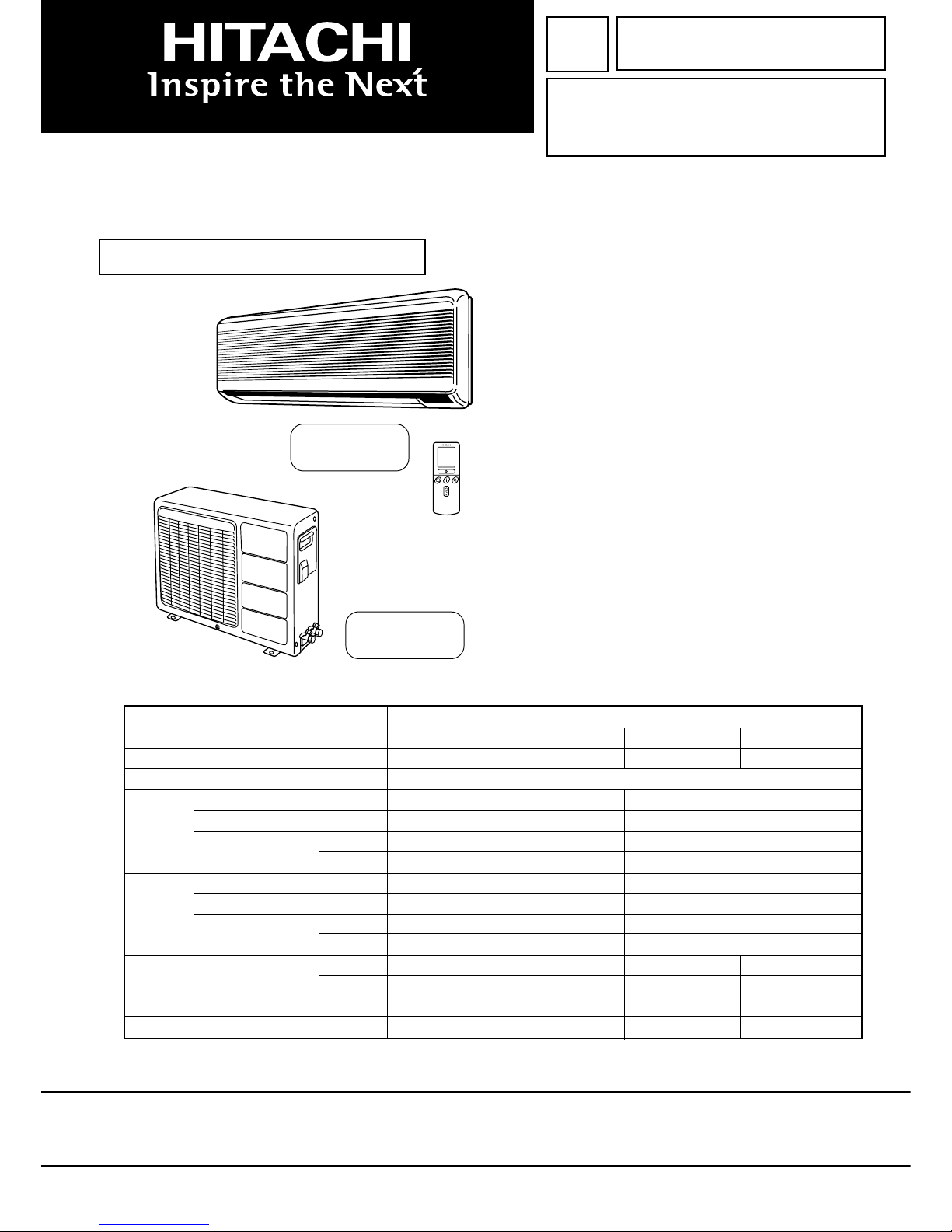
ROOM AIR CONDITIONER
INDOOR UNIT + OUTDOOR UNIT
MARCH 2004
H.A.P.M.
SPECIFICATIONS
TYPE
WALL TYPE
INDOOR UNIT OUTDOOR UNIT INDOOR UNIT OUTDOOR UNIT
MODEL RAS-07CH4 RAC-07CH4 RAS-09CH4 RAC-09CH4
POWER SOURCE 1Ø, 220 V, 50 Hz
TOTAL INPUT (W) 680 870
COOLING
TOTAL AMPERES (A) 3.15 4.1
CAPACITY
(kW) 2.05 2.50
(B.T.U./h) 7,000 8,500
TOTAL INPUT (W) 630 860
HEATING
TOTAL AMPERES (A) 3.0 4.1
CAPACITY
(kW) 2.15 2.65
(B.T.U./h) 7,850 10,000
W 785 700 785 700
DIMENSIONS (mm) H 265 570 265 570
D 168 210 168 210
NET WEIGHT (kg) 7 26 7 26
RAS-07CH4/RAC-07CH4
RAS-09CH4/RAC-09CH4
Page 2
SAFETY DURING REPAIR WORK
1. In order to disassemble and repair the
unit in question, be sure to disconnect
the power cord plug from the power
outlet before starting the work.
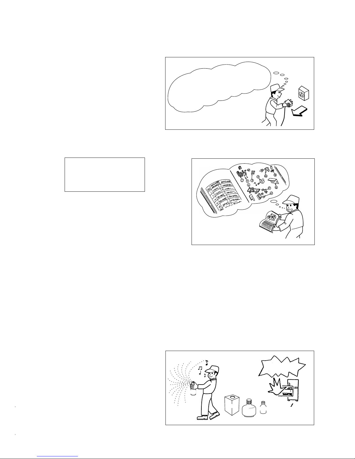
2. If it is necessary to replace any parts, they should be replaced with respective genuine parts for the unit,
and the replacement must be effected in correct manner according to the instructions in the Service Manual
of the unit.
3. After completion of repairs, the initial state should
be restored.
4. Lead wires should be connected and laid as in
the initial state.
5. Modification of the unit by the user himself should
absolutely be prohibited.
6. Tools and measuring instruments for use in repairs or inspection should be accurately calibrated in
advance.
7. In installing the unit having been repaired, be careful to prevent the occurrence of any accident such as
electrical shock, leak of current, or bodily injury due to the drop of any part.
8. To check the insulation of the unit, measure the insulation resistance between the power cord plug and
grounding terminal of the unit. The insulation resistance should be 1MΩ or more as measured by a 500V
DC megger.
9. The initial location of installation such as window, floor or the other should be checked for being safe
enough to support the repaired unit again.
If it is found not so strong and safe, the unit should be installed at the initial location after reinforced or at a
new location.
10. Any inflammable object must not be
placed about the location of installation.
11. Check the grounding to see whether it
is proper or not, and if it is found
improper, connect the grounding
terminal to the earth.
If the contacts of electrical parts
are defective, replace the
electrical parts without trying to
repair them.
Spray
gasoline
gasbombe
thinner
DANGER
First, I must disconnect
the power cord plug
from the power outlet.
Page 3

– 1 –
HITACHI IC401TH1 ,188UV
WORKING STANDARDS FOR PREVENTING BREAKAGE OF SEMICONDUCTORS
1. Scope
The standards provide for items to be generally observed in carrying and handling semiconductors in relative
manufacturers during maintenance and handling thereof. (They apply the same to handling of abnormal goods
such as rejected goods being returned).
2. Object parts
(1) Micro computer
(2) Integrated circuits (IC)
(3) Field-effect transistors (FET)
(4) P.C. boards or the like on which the parts mentioned in (1) and (2) of this paragraph are equipped.
3. Items to be observed in handling
(1) Use a conductive container for carrying and storing of parts. (Even rejected goods should be handled in the
same way).
(2) When any part is handled uncovered (in counting, packing and the like), the handling person must always
use himself as a body earth. (Make yourself a body earth by passing one M ohm earth resistance through a
ring or bracelet).
(3) Be careful not to touch the parts with your clothing when you hold a part even if a body earth is being taken.
(4) Be sure to place a part on a metal plate with grounding.
(5) Be careful not to fail to turn off power when you repair the printed circuit board. At the same time, try to repair
the printed circuit board on a grounded metal plate.
IC
IC
A conductive polyvinyl bag
Conductive sponge
Fig. 1 Conductive Container
Fig. 2 Body Earth
Body earth
(Elimik conductive band)
Clip for connection with
a grounding wire
Page 4

– 2 –
(6) Use a three wire type soldering iron including a grounding wire.
Bare copper wire (for body earth)
Working table
Resistor of 1 MΩ (1/2W)
Earth wire
Fig. 3. Grounding of the working table
Screw stop at the screwed
part using a rag plate
Soldering iron
Grounding wire
Fig. 4. Grounding a soldering iron
Use a high insulation mode (100V, 10MΩ or higher) when ordinary iron is to be used.
(7) In checking circuits for maintenance, inspection or some others, be careful not to have the test probes of the
measuring instrument shortcircuit a load circuit or the like.
Metal plate (of aluminium, stainless steel, etc.)
Staple
Page 5

– 3 –
CAUTION
1. In quiet or stop operation, slight flowing noise of refrigerant in the refrigerating cycle is heard occasionally,
but this noise is not abnormal for the operation.
2. When it thunders near by, it is recommend to stop the operation and to disconnect the power cord plug from
the power outlet for safety.
3. If the room air conditioner is stopped by setting the temperature or mis-operation, and then re-started in a
moment, cooling operation does not start for 3 minutes, it is not abnormal and this is the result of the
operation of IC delay circuit. This IC delay circuit ensures that there is no danger of blowing fuse or damaging
parts even if operation is restarted accidentally.
4. This room air conditioner should not be used at the cooling operation when the outside temperature is
below 20°C.
5. When the operation knob is set to “COOL” from another position, IC delay circuit functions and stops the
compressor for the first 3 minutes, which is not an abnormal phenomenon.
Page 6

– 4 –
There are 3 directions allowed,
namely, horizontally perpendicular to the unit, vertically
down from right, horizontally
out from right.
Don’t form the piping
downward at the left of the unit.
Horizontally
perpendicular
to the unit
Connection
20
Dimension of Mounting Stand
of the outdoor unit
(unit : mm)
35
12
225
8
35
500
100
above 100mm
above 50mm
above 100mm
2,300mm or more
above 300mm
must not bend
about 0.45m
Maximum pipe length 10m
Minimum pipe length 5m
* above 50mm
* give clearance
as wide as possible
above 200mm
* above 200mm
above 100mm
above 50mm when
installed on the
ceiling of balcony
above 200mm
The indoor piping should be
insulated with the enclosed
insulation pipe. (If the
insulator is insufficient, please
use commercial products).
The difference in height
between the indoor and
outdoor unit should be kept
below 5m.
The connecting pipe, no
matter big or small, should all
be insulated with insulation
pipe and then wrapped with
vinyl tape. (The insulator will
deteriorate if it is not wrapped
with tape).
The connection of insulated
drain hose.
inner diameter ø 16mm
Please use insulated drain
hose for the indoor piping
(commercial product.)
•
•
mounting stand
Plug
Be sure to
completely
seal any gap
with putty.
The Length of Indoor Unit
Connecting Cord
about
0.9m
about 1.6m
Do not alter the power cord.
Cut away shaded
portion, and finish
the edge of the
opening so that
there is no burr.
Figure showing the Installation
of Indoor and Outdoor unit.
Page 7
– 5 –
SPECIFICATIONS
MODEL RAS-07CH4 RAC-07CH4 RAS-09CH4 RAC-09CH4
FAN MOTOR 10 W 20 W 10 W 20 W
FAN MOTOR CAPACITOR 1 µF, 400 V 1.5 µF, 400 V 1 µF, 400 V 1.5 µF, 400 V
FAN MOTOR PROTECTOR
YES (INTERNAL) YES (INTERNAL) YES (INTERNAL) YES (INTERNAL)
COMPRESSOR NO G333DB2Z NO G533QB9Z
COMPRESSOR MOTOR CAPACITOR NO 30 µF, 400 V NO 30 µF, 400 V
OVERLOAD PROTECTOR NO YES NO YES
OVERHEAT PROTECTOR NO NO NO NO
FUSE (for MICRO COMPUTER) 3.0 A NO
POWER RELAY G4A NO G4A NO
POWER SWITCH YES NO YES NO
TEMPORARY SWITCH YES NO YES NO
SERVICE SWITCH YES NO YES NO
TRANSFORMER YES NO YES NO
VARISTOR 450NR NO 450NR NO
NOISE SUPPRESSOR NO NO NO NO
REMOTE CONTROL SWITCH (LIQUID CRYSTAL)
YES NO YES NO
THERMOSTAT YES (IC) NO YES (IC) NO
FUSE CAPACITY 10 A TIME DELAY FUSE
UNIT -------- ❇ 630 g -------- ❇ 700 g
REFRIGERANT CHARGING
VOLUME WITHOUT REFRIGERANT BECAUSE COUPLING IS FLARE
(Refrigerant 22) PIPES TYPE.
P - 105 VK1 (5m), P - 108 VK1 (8m)
❇ 630g for piping set of 5 ~ 8m.
❇ 700g for piping set of 5 ~ 8m.
Page 8
– 6 –
SAFETY PRECAUTION
●
Please read the “Safety Precaution” carefully before operating the unit to ensure correct usage of the unit.
●
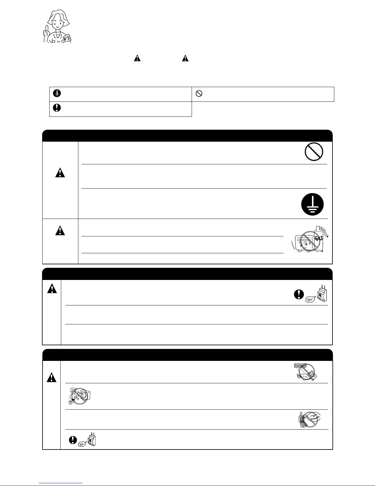
Pay special attention to signs of “ Warning” and “ Caution”. The “Warning” section contains matters which,
if not observed strictly, may cause death or serious injury. The “Caution” section contains matters which may
result in serious consequences if not observed properly. Please observe all instructions strictly to ensure safety.
●
The sign indicate the following meanings.
●
Please keep this manual after reading.
WARNING
PRECAUTIONS DURING INSTALLATION
●
●
●
●
●
●
Please ensure smooth flow of water when installing the drain hose.
CAUTION
PRECAUTIONS DURING SHIFTING OR MAINTENANCE
PRECAUTIONS DURING OPERATION
●
Avoid an extended period of direct air flow for your health.
W
A
R
N
I
N
G
●
●
●
●
●
During thunder storm, disconnect and turn off the circuit breaker.
●
Do not use any conductor as fuse wire, this could cause fatal accident.
Make sure to connect earth line.
Indicates the instructions that must be followed.
The sign in the figure indicates prohibition.
W
A
R
N
I
N
G
Do not reconstruct the unit.
Water leakage, fault, short circuit or fire may occur if you reconstruct the
unit by yourself.
Please ask your sales agent or qualified technician for the installation of
your unit. Water leakage, short circuit or fire may occur if you install the unit
by yourself.
A circuit breaker should be installed depending on the mounting site of the
unit. Without a circuit breaker, the danger of electric shock exists.
Do not install near location where there is flammable gas. The outdoor unit
may catch fire if flammable gas leaks around it.
Please use earth line.
Do not place the earth line near water or gas pipes, lightning-conductor, or
the earth line of telephone. Improper installation of earth line may cause
electric shock.
Should abnormal situation arises (like burning smell), please stop operating the unit
and turn off the circuit breaker. Contact your agent. Fault, short circuit or fire may
occur if you continue to operate the unit under abnormal situation.
Please contact your agent for maintenance. Improper self maintenance may cause
electric shock and fire.
Please contact your agent if you need to remove and reinstall the unit. Electric
shock or fire may occur if you remove and reinstall the unit yourself improperly.
Do not insert a finger, a rod or other objects into the air outlet or inlet. As the
fan is rotating at a high speed, it will cause injury. Before cleaning, be sure
to stop the operation and turn the breaker OFF.
Page 9

– 7 –
PRECAUTIONS DURING OPERATION
●
●
●
●
●
●
●
●
●
●
●
C
A
U
T
I
O
N
●
●
●
The product shall be operated under the manufacturer specification and
not for any other intended use.
When operating the unit with burning equipments, regularly ventilate the
room to avoid oxygen insufficiency.
Please ensure that outdoor mounting frame is always stable, firm and
without defect. If not, the outdoor unit may collapse and cause danger.
Turn off the circuit breaker if the unit is not to be operated for a long period.
Do not use any aerosol or hair sprays near the indoor unit. This chemical
can adhere on heat exchanger fin and blocked the evaporation water flow
to drain pan. The water will drop on tangential fan and cause water
splashing out from indoor unit.
Do not put water container (like vase) on the indoor unit to avoid water
dripping into the unit. Dripping water will damage the insulator inside the
unit and causes short-circuit.
When operating the unit with the door and windows opened, (the room humidity is always above
80%) and with the air deflector facing down or moving automatically for a long period of time,
water will condense on the air deflector and drips down occasionally. This will wet your furniture.
Therefore, do not operate under such condition for a long time.
If the amount of heat in the room is above the cooling or heating capability of the unit (for
example: more people entering the room, using heating equipments and etc.), the preset room
temperature cannot be achieved.
Do not direct the cool air coming out from the air-conditioner panel to face
household heating apparatus as this may affect the working of apparatus
such as the electric kettle, oven etc.
Do not attempt to operate the unit with wet hands, this could cause fatal
accident.
Do not splash or direct water to the body of the unit when cleaning it as this
may cause short circuit.
Please switch off the unit and turn off the circuit breaker during cleaning, the
high-speed fan inside the unit may cause danger.
Do not climb on the outdoor unit or put objects on it.
Do not place plants directly under the air flow as it is bad for the plants.
Page 10
– 8 –
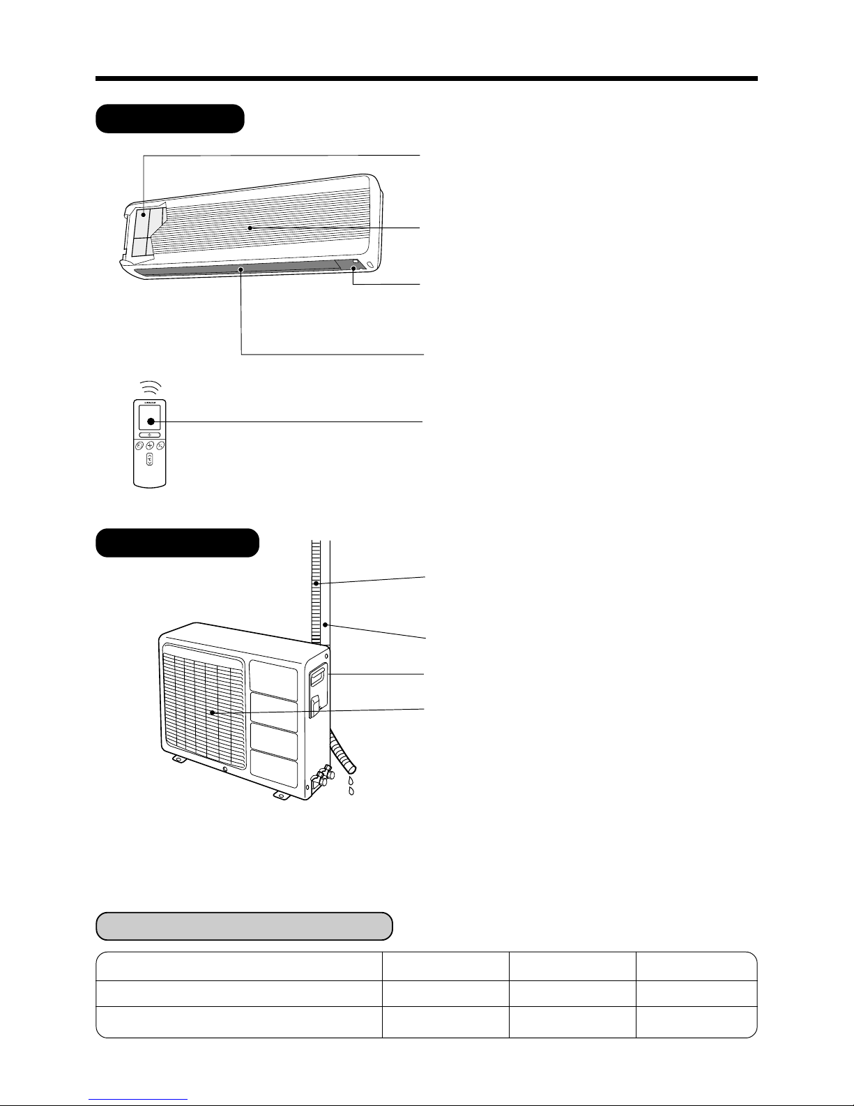
NAMES AND FUNCTIONS OF EACH PART
INDOOR UNIT
OUTDOOR UNIT
Air Filter
To prevent dust from coming into the indoor unit.
(Refer page 24)
Suction Grille (Air Inlet)
Indoor unit Indicators
Light indicator showing the operation condition.
(Refer page 9)
Horizontal Deflector • Vertical Deflector
(Air outlet)
(Refer page 20)
Remote Control
Send out operation signal to the indoor unit.
So as to operate the whole unit.
(Refer page 10)
Drain pipe
Condensed water drain to outside.
Connecting cord
Air inlet (Back and left side)
Air outlet
Blow out warm air.
MODEL NAME AND DIMENSIONS
MODEL WIDTH (mm) HEIGHT (mm) DEPTH (mm)
RAS-07CH4, RAS-09CH4 785 265 168
RAC-07CH4, RAC-09CH4 700 570 210
Page 11

– 9 –
OPERATION LAMP
This lamp lights during operation.
TIMER LAMP
This lamp lights when the timer is working.
SIGNAL RECEIVER
There will be a beep sound when this receiver receives
signal from remote control.
INDOOR UNIT INDICATORS
OPERATION INDICATOR
TEMPORARY SWITCH
Use this switch to start and stop when the remote controller
does not work. [Use non-conductor stick (example
toothpick)]
● By pressing the temporary switch, the operation is done
in previously set operation mode.
● When the operation is done using the temporary switch
after the power source is turned off and turn on again,
the operation is done in automatic mode.
POWER SWITCH
RAS-
RAS-
Temporary Switch
Press
about 7mm
Non-conductor Stick
Page 12
– 10 –
AUTO
HEAT
DEHUMIDIFY
COOL
FAN
FAN SPEED
LOW
MED
HI
SLEEPING
STOP (CANCEL)
START (RESERVE)
START/STOP
TIME
TIMER SET
TIMER SELECTOR
ON TIMER
OFF TIMER
AUTO SWING
RESET
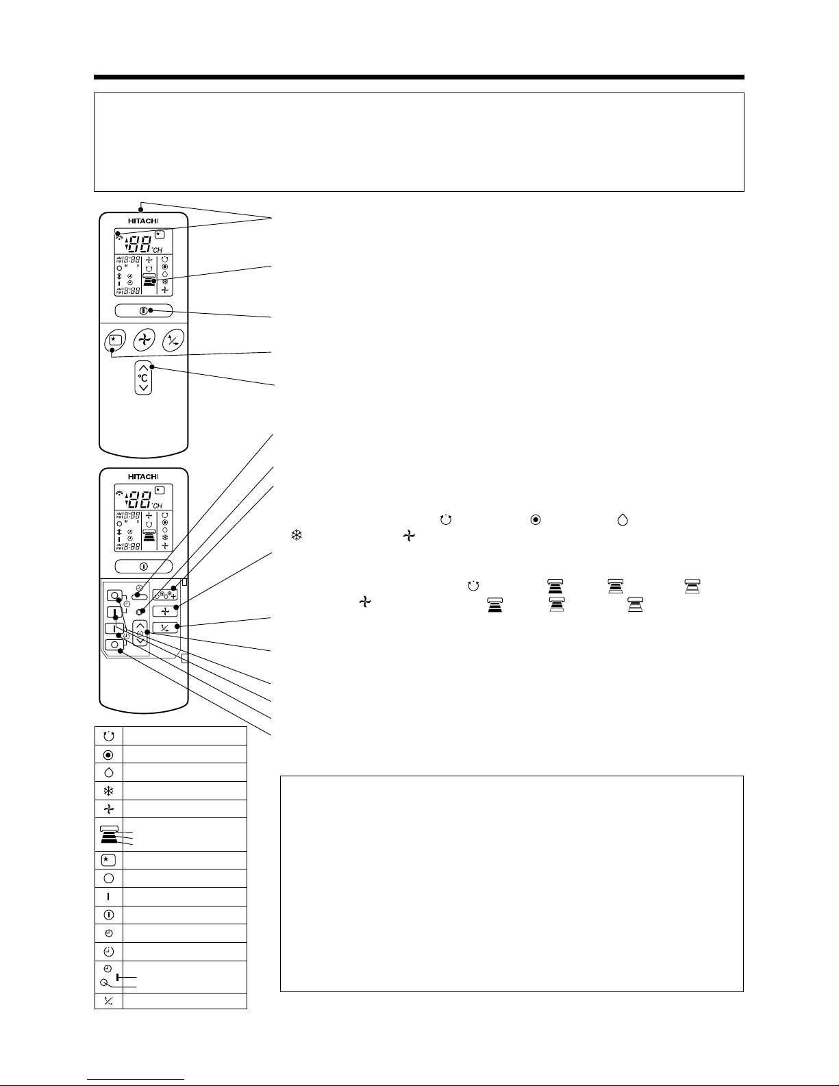
NAMES AND FUNCTIONS OF REMOTE CONTROL UNIT
REMOTE CONTROLLER
This controls the operation of the indoor unit. The range of control is about 7 meters. If indoor lighting is
controlled electronically, the range of control may be shorter.
This unit can be fixed on a wall using the fixture provided. Before fixing it, make sure the indoor unit can be
controlled from the remote controller.
Precautions for Use
● Do not put the remote controller in the following places.
● Under direct sunlight.
● In the vicinity of a heater.
● Handle the remote controller carefully. Do not drop it on the floor, and
protect it from water.
● Once the outdoor unit stops, it will not restart for about 3 minutes (unless
you turn the power switch off and on or unplug the power cord and plug
it in again).
This is to protect the device and does not indicate a failure.
● If you press the FUNCTION selector button during operation, the device
may stop for about 3 minutes for protection.
● Signal emitting window/transmission sign
Point this window toward the indoor unit when controlling it.
The transmission sign blinks when a signal is sent.
● Display
This indicates the room temperature selected, current time, timer status, function
and intensity of circulation selected.
● START/STOP button
Press this button to start operation. Press it again to stop operation.
● SLEEP button
Use this button to set the sleep timer.
● TEMPERATURE button
Use this button to raise or lower the temperature setting. (Keep pressed, and
the value will change more quickly.)
● TIME button
Use this button to set and check the time and date.
● RESET button
● FUNCTION selector
Use this button to select the operating mode. Every time you press it, the
mode will change from
(AUTO) to (HEAT) to (DEHUMIDIFY) to
(COOL) and to (FAN) cyclically.
● FAN SPEED selector
This determines the fan speed. Every time you press this button, the intensity
of circulation will change from
(AUTO) to (HI) to (MED) to (LOW)
(during the
(FAN) mode, from (HI) to (MED) to (LOW)).
● AUTO SWING button
Controls the angle of the horizontal air deflector.
● TIMER control
Use this button to set the timer.
● OFF-TIMER button Select the turn OFF time.
● ON-TIMER button Select the turn ON time.
● RESERVE button Time setting reservation.
● CANCEL button Cancel time reservation.
Page 13
– 11 –
C
RESET
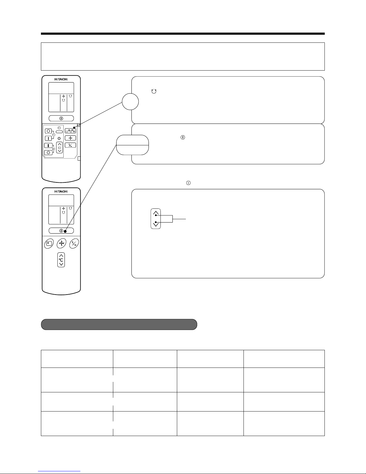
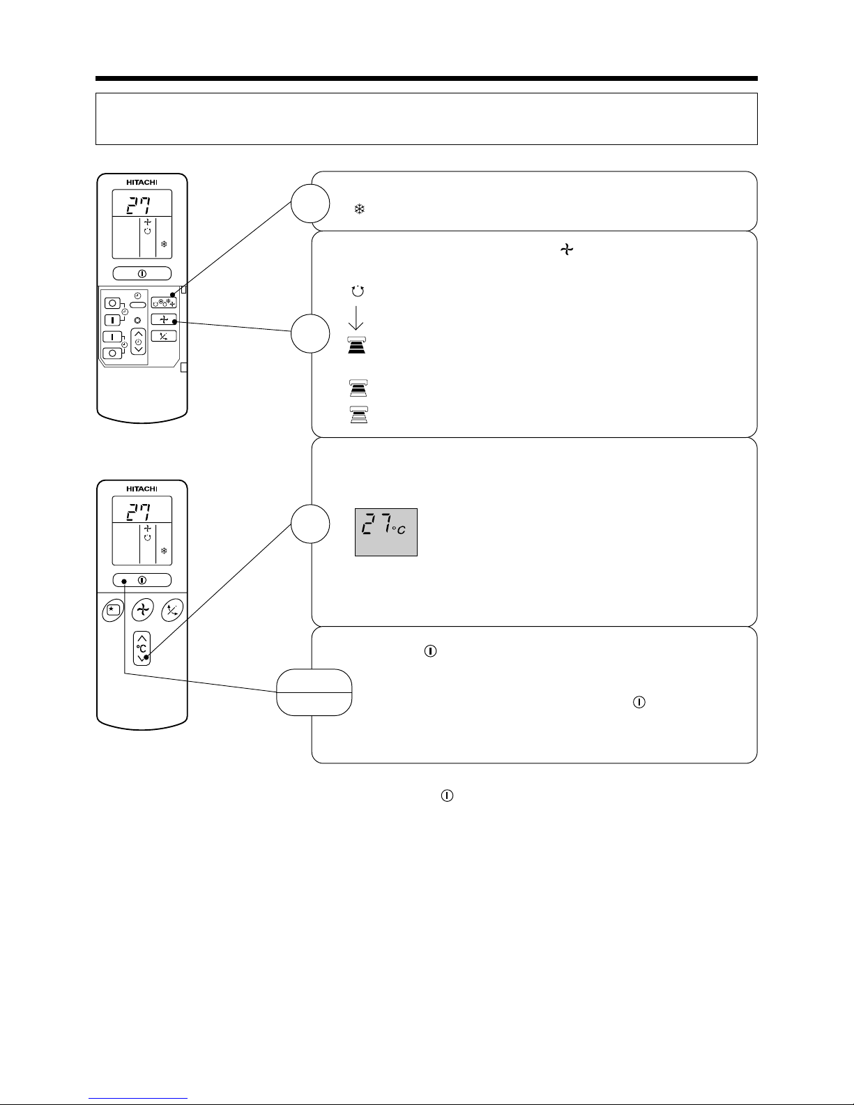
AUTOMATIC OPERATION
The device will automatically determine the mode of operation, HEAT, COOL or DEHUMIDIFY depending
on the initial room temperature. The selected mode of operation will not change when the room temperature
varies.
Press the FUNCTION selector so that the display indicates the
(AUTO) mode of operation.
● When AUTO has been selected, the device will automatically
determine the mode of operation, HEAT, COOL or
DEHUMIDIFY depending on the current room temperature.
Press the (START/STOP) button.
Operation starts with a beep.
Press the button again to stop operation.
■ As the settings are stored in memory in the remote controller, you only
have to press the
(START/STOP) button next time.
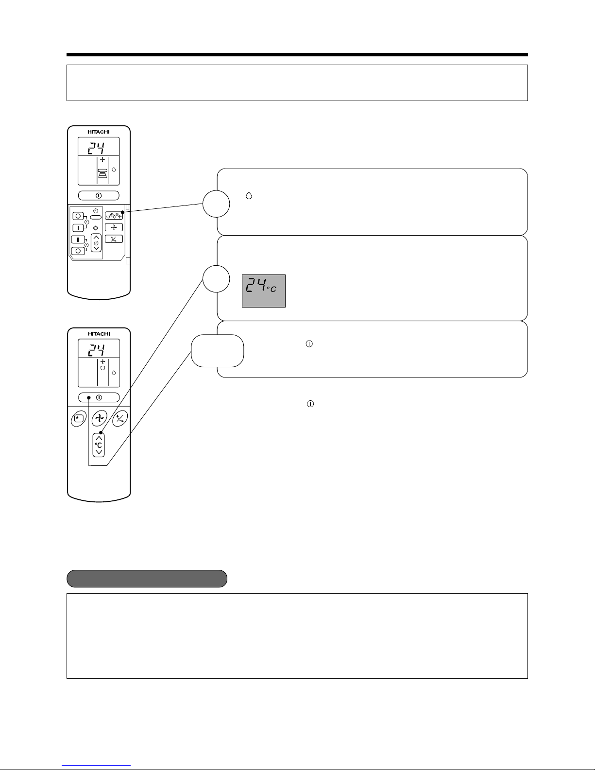
You can raise or lower the temperature setting as necessary by
maximum of 3°C.
Press the temperature button and the
temperature setting will change by 1°C each time.
● The preset temperature and the actual room temperature may
vary somewhat depending on conditions.
● The display does not indicate the preset temperature in the AUTO
mode. If you change the setting, the indoor unit will produce a
beep.
1
START
STOP
Initial room temperature
Function Temperature setting FAN SPEED
(approx.)
Over 27°C COOL 27°C
Under 23°C HEAT 23°C
HI at start, MED or LOW after
the preset temperature is
reached
Slightly lower than the
room temperature
HI at start, MED or LOW after
the preset temperature is
reached
■ CONDITION OF AUTOMATIC OPERATION
● The selected mode of operation will not change during the operation even though the room temperature
change.
23~27°C DEHUMIDIFY LOW
➡
➡
➡
Page 14

– 12 –
Press the FUNCTION selector so that the display indicates the
(HEAT).
Press the (START/STOP) button. Heating operation starts
with a beep. Press the button again to stop operation.
Set the desired fan speed with the
(FAN SPEED) button (the
display indicates the setting).
(AUTO) : The FAN SPEED is HI at first and varies to MED
automatically when the preset temperature has
been reached.
(HI) : Economical as the room will become warm
quickly.
But you may feel a chill at the beginning.
(MED) : Quiet.
(LOW) : More quiet.
Set the desired room temperature with the TEMPERATURE
button (the display indicates the setting).
The range of 18-22°C is recommended as the room
temperature for heating.
If the temperature setting is 20°C, the room
temperature will be controlled at around 20°C.
The temperature setting and the actual room temperature may
vary somewhat depending on conditions.
■ As the settings are stored in memory in the remote controller, you only
have to press the
(START/STOP) button next time.
HEATING OPERATION
Use the device for heating when the outdoor temperature is under 21°C.
When it is too warm (over 21°C), the heating function may not work in order to protect the device.
˚
C
˚
C
RESET
1
START
STOP
2
3
Page 15
– 13 –
DEHUMIDIFYING OPERATION
Use the device for dehumidifying when the room temperature is over 16°C.
When it is under 15°C, the dehumidifying function will not work.
When the room temperature is higher than the temperature setting: The device will dehumidify the room,
reducing the room temperature to the preset level.
When the room temperature is lower than the temperature setting: Dehumidifying will be performed at the
temperature setting slightly lower than the current room temperature, regardless of the temperature setting.
The function will stop (the indoor unit will stop emitting air) as soon as the room temperature becomes lower
than the setting temperature.
■ Dehumidifying Function
Press the FUNCTION selector so that the display indicates
(DEHUMIDIFY).
The FAN SPEED is set at LOW automatically.
The FAN SPEED button does not work.
Set the desired room temperature with the TEMPERATURE
button (the display indicates the setting).
The range of 20-26°C is recommended as the room
temperature for dehumidifying.
■ As the settings are stored in memory in the remote controller, you only
have to press the
(START/STOP) button next time.
Press the (START/STOP) button. Dehumidifying operation
starts with a beep. Press the button again to stop operation.
˚
C
˚
C
RESET
1
START
STOP
2
Page 16
– 14 –
COOLING OPERATION
Use the device for cooling when the outdoor temperature is 22-42°C.
If humidity is very high (over 80%) indoors, some dew may form on the air outlet grille of the indoor unit.
Press the FUNCTION selector so that the display indicates the
(COOL).
Set the desired fan speed with the
(FAN SPEED) button (the
display indicates the setting).
(AUTO) : The FAN SPEED is HI at first and varies to MED
automatically when the preset temperature has
been reached.
(HI) : Economical as the room will become warm
quickly.
But you may feel a chill at the beginning.
(MED) : Quiet.
(LOW) : More quiet.
Set the desired room temperature with the TEMPERATURE
button (the display indicates the setting).
The range of 25-28°C is recommended as the room
temperature for cooling.
If the temperature setting is 27°C, the room
temperature will be controlled at around 27°C.
The temperature setting and the actual room temperature may
vary somewhat depending on conditions.
Press the (START/STOP) button. Cooling operation starts
with a beep. Press the button again to stop operation. The cooling
function does not start if the temperature setting is higher than
the current room temperature (even though the
(OPERATION)
lamp lights). The cooling function will start as soon as you set
the temperature below the current room temperature.
■ As the settings are stored in memory in the remote controller, you only
have to press the
(START/STOP) button next time.
˚
C
˚
C
RESET
1
2
3
START
STOP
Page 17
– 15 –
RESET
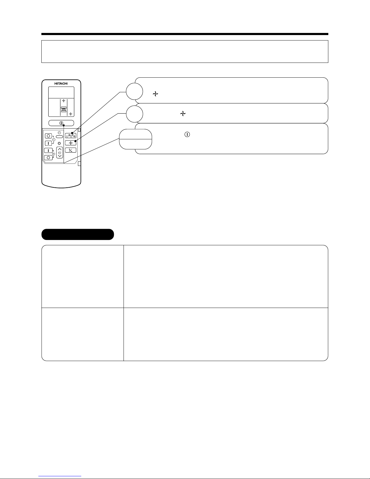
FAN OPERATION
You can use the device simply as an air circulator. Use this function to dry the interior of the indoor unit at the
end of summer.
FAN SPEED (AUTO) …
When the AUTO fan speed mode is set in the cooling/heating operation:
For the heating operation
● The fan speed will automatically change according to the temperature of
discharged air.
● When the difference of room temperature and setting temperature is
large, fan starts to run at HI speed.
● When the room temperature reaches setting temperature, fan speed
changes to LOW automatically.
For the cooling operation
● When the difference of room temperature and setting temperature is
large, fan starts to run at HI speed.
● After room temperature reaches the preset temperature, the cooling
operation, which changes the fan speed and room temperature to obtain
optimum conditions for natural healthful cooling will be performed.
Press the FUNCTION selector so that the display indicates the
(FAN).
1
Press the (FAN SPEED) button.
2
START
STOP
Press the (START/STOP) button. Fan operation starts with
a beep. Press the button again to stop operation.
Page 18
– 16 –
AM
Start
Stop
PM
Start Stop
PM
AM
PM
●
●
●
1
OFF-Timer
After you change the
batteries;
1
1
1
2
ON-Timer
Time, Day, Month
●
The device will turn on at
the designated times.
M D
M D
AM
STOP
Start
ON/OFF-Timer
Set the current month and
day with the TIMER control
button.
The device will turn on (off) and
off (on) at the designated times.
The switching occurs first at the
preset time that comes earlier.
The arrow mark appearing on the
display indicates the sequence of
switching operations.
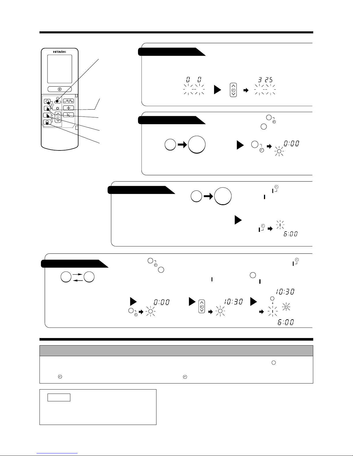
Press the (ON-OFF)
button so that the (OFF)
mark blinks.
Set the turn-off time
with the TIMER control
button.
Press the (RESERVE)
button.
3
Press the (ONTIMER) button so that the
(OFF) mark lights and
the (ON) mark blinks.
Press the (ON-TIMER)
button the (ON) mark blinks
on the display.
Press the (OFF-TIMER)
button. The (OFF) mark blinks
on the display.
You can set the device to turn off
at the present time.
RESET
HOW TO SET THE TIMER
How to Cancel Reservation
Point the signal window of the remote controller toward the indoor unit, and press the (CANCEL)
button.
The (RESERVED) sign goes out with a beep and the (TIMER) lamp turns off on the indoor unit.
NOTE
You can set only one of the OFF-timer,
ON-timer and ON/OFF-timer.
TIME, DAY,
MONTH
(current time,
day, month)
OFF TIMER
ON TIMER
RESERVE
CANCEL
Page 19
– 17 –
Point the signal window of the remote controller toward the indoor unit, and
press the (RESERVE) button.
The (OFF) mark starts lighting instead of flashing and the sign (RESERVED)
lights. A beep occurs and the (TIMER) lamp lights on the indoor unit.
PM
PM
3
●
●
2
3
Example: The current time is 1:30 p.m.
2
The setting of turn-off time is now complete.
Example: The device will turn off at 11:00p.m.
4
2
4
PM PM
AM
PM
AM
AM
PM
PM
Point the signal window of the remote controller toward the indoor unit, and
press the (RESERVE) button.
The (ON) mark starts lighting instead of flashing and the sign (RESERVED)
lights. A beep occurs and the (TIMER) lamp lights on the indoor unit.
3
Point the signal window of the remote controller toward the indoor unit, and
press the (RESERVE) button.
The (ON) mark starts lighting instead of flashing and the sign (RESERVED)
lights. A beep occurs and the (TIMER) lamp lights on the indoor unit.
5
AM
AM
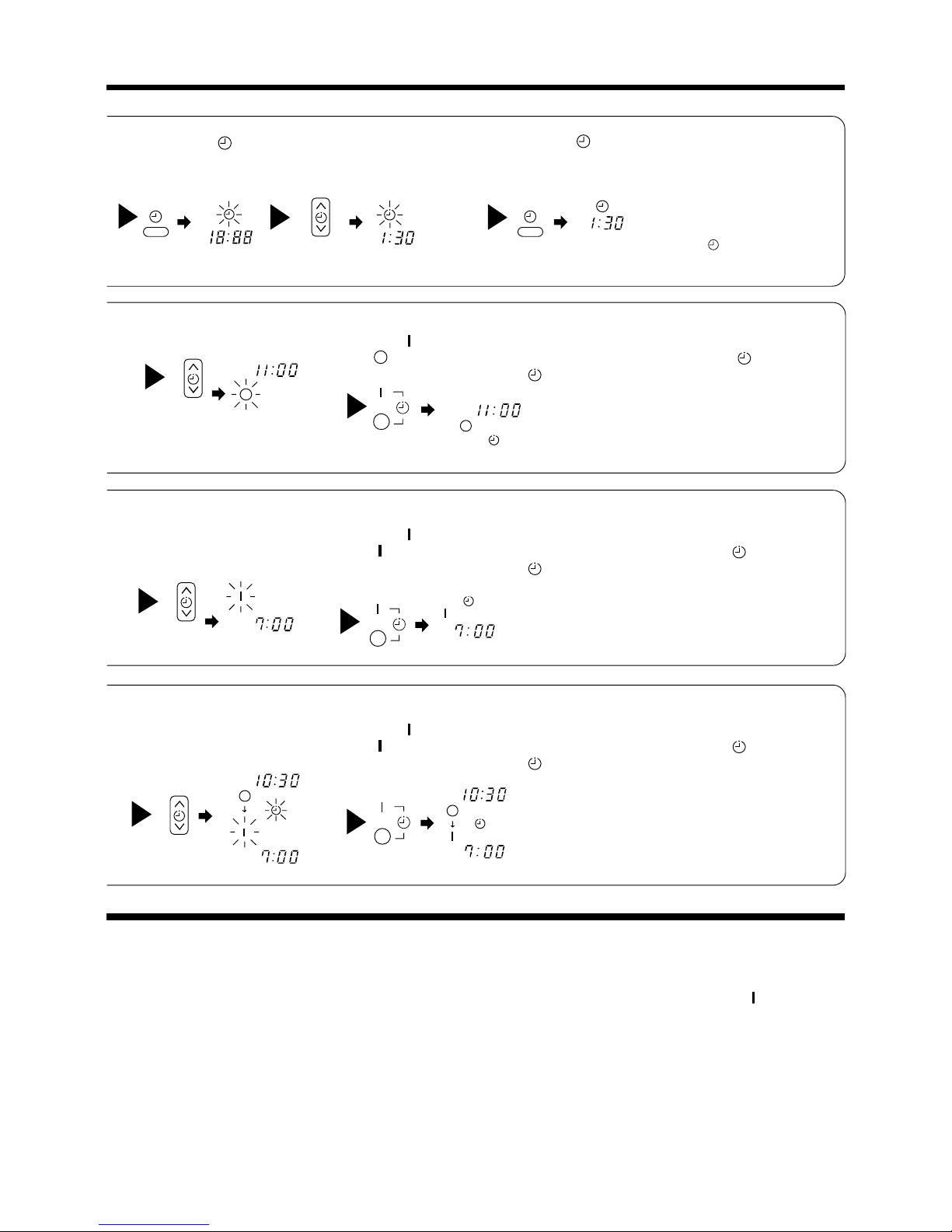
Press the
(TIME) button.
Set the current time with
the TIMER control button.
Set the turn-off time with
the TIMER control button.
Set the turn-on time with
the TIMER control button.
Set the turn-on time with
the TIMER control button.
Press the (TIME) button again.
The time indication starts lighting instead
of flashing.
The time indication will disappear
automatically in 10 second.
To check the current time setting,
press the (TIME) button twice.
The setting of the current time is
now complete.
Example:
The device will automatically turn on earlier so that
the preset temperature can be reached at 7:00 a.m.
The setting of the turn-on time is now complete.
Example:
The device will turn off at 10:30 p.m. and then
automatically turn on earlier so that the preset
temperature can be reached at 7:00 a.m.
The settings of the turn-on/off times are now complete.
● The timer may be used in three ways: off-timer, on-timer and ON/OFF (OFF/ON)-timer. Set the current time
at first because it serves as a reference.
● As the time settings are stored in memory in the remote controller, you only have to press the (RESERVE)
button in order to use the same settings next time.
Page 20

– 18 –
1
1 hour 2 hours 3 hours 7 hours
Sleep timer off
2
H
Sleep
timer
Start
H
H
AM
AM
HOW TO SET THE SLEEP TIMER
Set the current time at first if it is not set before (see the pages for setting the current
time). Press the
(SLEEP) button, and the display changes as shown below.
How to Cancel Reservation
Point the signal window of the remote controller toward the indoor unit, and press the (CANCEL)
button.
The (RESERVED) sign goes out with a beep and the (TIMER) lamp turns off on the indoor unit.
Mode Indication
Sleep timer
SLEEP
Sleep Timer: The device will continue working for the designated
number of hours and then turn off.
Point the signal window of the remote controller toward the indoor
unit, and press the SLEEP button.
The timer information will be displayed on the remote controller.
The TIMER lamp lights with a beep from the indoor unit. When the
sleep timer has been set, the display indicates the turn-off time.
Example: If you set 3 hours sleep
time at 11:38 p.m., the turn-off
time is 2:38 a.m.
The device will be turned off by the sleep
timer and turned on by on-timer.
Set the On-timer.
Press the
(SLEEP) button and set the sleep timer.
Example:
In this case, the device will turn off
in 2 hours (at 1:38 a.m.) and turn
on early so that the preset
temperature will be almost reached
at 6:00 next morning.
Page 21

– 19 –
Explanation of the sleep timer
The device will control the FAN SPEED and room temperature automatically so as to be quiet
and good for people’s health.
You can set the sleep timer to turn off after 1, 2, 3 or 7 hours. The FAN SPEED and room
temperature will be controlled as shown below.
Operation with the sleep timer
“ ”
“ ”
“ ”
“ ”
Function Operation
Heating
Cooling
and
dehumidifying
Fan
The room temperature will be
controlled 5°C below the
temperature and the FAN
SPEED will be set to LOW setting
30 minutes after the setting of
the sleep timer.
The room temperature will be
controlled 2°C above the
temperature and the FAN
SPEED will be set to LOW setting
30 minutes after the setting of
the sleep timer.
The settings of room temperature and circulation are varied.
2°C
5°C
Sleep
timer set
2 hours
later
30 minutes later
30 minutes later
3 hours later
7 hours later
3 hours later1 hour later
Sleep timer set
2 hours
later
6 hours
later
7 hours
later
NOTE
●
If date or current time is not set, sleep timer can not be set.
●
If you set the sleep timer after the off-, on/off- or off/on-timer has been set, the sleep timer becomes
effective instead of the off-, on/off- or off/on-timer set earlier.
●
You can not set other timer during sleep timer operation.
●
After sleep timer time is up and when press sleep button again, the sleep timer will be set as last setting.
●
Sleep timer effective only once.
Page 22

– 20 –
When cooling
dehumidifying
about 25°
about 20°
When heating
about 35°
CAUTION
●
When operating the unit in cooling operation with the air deflector facing down and moving
automatically for a long period of time, water will condensed on the air deflector and drips down
occasionally. This will wet your furniture.
ADJUSTING THE AIR DEFLECTORS
1
Adjustment of the conditioned air in the upward and
downward directions.
According to “Dehumidifying” and “Cooling” operation,
the horizontal air deflector is automatically set to the
proper angle suitable for each operation.
The deflector can be swung up and down and also
set to the desired angle using the “
(AUTO
SWING)” button. (If the angle of the deflector is
changed, it will not return to the auto-set position
after operations start unless the operation mode is
switched.)
●
If the “
(AUTO SWING)” button is pressed
once, the horizontal air deflector swings up and
down. If the button is pressed again, the deflector
stops in its current position. Several seconds
(about 12 seconds) may be required before the
deflector starts to move.
●
In “Cooling” operation, do not keep the horizontal
air deflector swinging for a long time. Some dew
may form on the horizontal air deflector and
some dew may drop.
2
Adjustment of the conditioned air to the left and right.
Hold the vertical air deflector as shown in the figure
and adjust the conditioned air to the left and right.
Page 23

– 21 –
Remove the cover as shown in the figure and take out the
old batteries.
1
2
Install the new batteries.
The direction of the batteries should match the marks in the
case.
Push and pull to the
direction of arrow
CAUTION
1. Do not use new and old batteries, or different kinds of batteries
together.
2. Take out the batteries when you do not use the remote
controller for 2 or 3 months.
HOW TO EXCHANGE THE BATTERIES IN THE REMOTE CONTROLLER
Page 24

– 22 –
THE IDEAL WAYS OF OPERATION
Suitable Room Temperature
Warning
Freezing temperature is
bad for health and a
waste of electric power.
Install curtain or blinds
It is possible to
reduce heat
entering the
room through
windows.
Ventilation Effective Usage Of Timer
Do Not Forget To Clean The Air Filter
Please Adjust Suitable Temperature For
Baby and Children
Caution
Do not close the room for a long period of time.
Occasionally open the door and windows to
allow the
entrance of
fresh air.
At night, please use the “OFF or ON timer
operation mode”, together with your wake up
time in the morning. This will enable you to enjoy
a comfortable room temperature. Please use
the timer effectively.
Dusty air filter will reduce the air volume and the
cooling efficiency. To prevent from wasting
electric energy, please clean the filter every 2
weeks.
Please pay attention to the room temperature
and air flow direction when operating the unit
for baby, children and old folks who have
difficulty in movement.
Page 25

– 23 –
FOR USER’S INFORMATION
The Air Conditioner And The Heat Source In The Room
Caution
If the amount of heat in the room is above the cooling
capability of the air conditioner (for example: more
people entering the room, using heating equipments
and etc.), the preset room temperature cannot be
achieved.
Not Operating For A Long Time
When the indoor unit is not to be used for a long
period of time, please switch off the power from the
mains. If the power from mains remains “ON”, the
indoor unit still consumes about 8W in the operation
control circuit even if it is in “OFF” mode.
OFF
Interference From Electrical Products
Caution
To avoid noise interference, please place the indoor
unit and its remote controller at least 1m away from
electrical products.
When Lightning Occurs
Warning
To protect the whole unit during lightning, please
stop operating the unit and remove the plug from the
socket.
To prevent
interference,
place at least
1m away.
TV
Inverter-type
fluorescent
lamp.
Page 26

– 24 –
Before the cleaning, stop operation and disconnect the power supply.
1. AIR FILTER
2. CLEANING OF FRONT COVER, ETC.
●
!
CAUTION
●
●
●
NOTE:
●
●
●
●
●
!
CAUTION
1.
2.
PROCEDURE
REMOVING METHOD
1.
2.
INSTALLATION METHOD
CAUTION
!
B
E
N
Z
I
N
E
A
C
I
D
Clean the air filter, as it removes dust inside the room. In case the air filter is full of dust, the air
flow will decrease and the cooling capacity will be reduced. Further, noise may occur. Be sure to
clean the filter following the procedure below.
Do not wash with hot water at more than 40°C. The
filter may shrink.
When washing it, shake off moisture completely and
dry it in the shade; do not expose it directly to the
sun. The filter may shrink.
Do not operate the air conditioner with the filter
removed. Dust may enter the air conditioner and
cause trouble.
This model has an air cleaning filter. The cooling
capacity is slightly weakened and the cooling speed
becomes slower when the air cleaning filter is
used.So, set the fan speed to “HIGH” when using it
in this condition.
Recommended to replace the air cleaning filter after
every 3 months for normal usage. Type number for
this air cleaning filter is <SPX-CFH3>. Please use
this number for ordering when you want to renew it.
Remove dust from the filter using a vacuum cleaner. If
there is too much dust, use neutral detergent. After
using neutral detergent, wash with clean water and
dry in the shade.
Set the filter with “FRONT” mark facing
front, and slot in them to the original
state.
Never use hot water (above 40°C),
benzine, gasoline, acid, thinner or
a brush, because they will damage
the plastic surface and the coating.
Wipe it with a soft dry cloth.
When it is excessively dirty, wipe
with a soft cloth soaked in
luke warm water or neutral
detergent. Then wipe thoroughly
with a soft dry cloth.
Wipe the remote controller
thoroughly with a soft dry cloth.
Press the “ (AUTO SWING)”
button, let the deflector facing
downward.
Remove the filter from the lower side
as the arrow shown.
Install the filters.
(Set them with “FRONT”
mark facing front.)
Slot in the filter to the original state.
MAINTENANCE
Page 27

– 25 –
3. MAINTENANCE AT BEGINNING OF LONG OFF PERIOD
1
2
3
REGULAR INSPECTION
Is the plug of power line firmly plugged into the socket?
(Please ensure no loose contact between them).
Is the earth line disconnected or broken?
Is the mounting frame seriously affected by rust and is the
outdoor unit tilted or unstable?
Air
Blow
Confirm
PLEASE CHECK THE FOLLOWING POINTS EVERY EITHER HALF YEARLY
OR YEARLY. CONTACT YOUR SALES AGENT SHOULD YOU NEED ANY
HELP.
Running the unit setting the operation mode to
(FAN) and the fan speed to HI for about half a day
on a fine day, and dry the whole of the unit.
Disconnect the power plug.
Page 28
– 26 –
When it does not operate
●
Is the fuse all right?
●
Is the voltage extremely high or low?
●
Is the circuit breaker “ON”?
●
Was the air filter cleaned?
●
Does sunlight fall directly on the outdoor unit?
●
Is the air flow of the outdoor unit obstructed?
●
Are the doors or windows opened, or is there any source
ofheat in the room?
●
Is the set temperature suitable?
CONDITION CHECK THE FOLLOWING POINTS
Notes
●
In quiet operation or stopping the operation, the following phenomena
may occassionally occur, but they are not abnormal for the operation.
(1) Slight flowing noise of refrigerant in the refrigerating cycle.
(2) Slight rubbing noise from the fan casing which is cooled and then
gradually warmed as operation stops.
●
The odor will possibly be emitted from the room air conditioner because
the various odor, emitted by smoke, foodstuffs, cosmetics and so on,
sticks to it. So please clean the air filter and the evaporator regularly to
reduce the odor.
●
●
When it does not cool well
WHEN ASKING FOR SERVICE, CHECK THE FOLLOWING POINTS.
Please contact your sales agent immediately if the air conditioner still fails to operate normally after the
above inspections. Inform your agent of the model of your unit, production number, date of installation.
Please also inform him regarding the fault.
Power supply shall be connected at the rated voltage, otherwise the unit will be broken or could not reach
the specified capacity.
Please note:
On switching on the equipment, particularly when the room light is dimmed, a slight brightness fluctuation
may occur. This is of no consequence.
The conditions of the local Power Supply Companies are to be observed.
AFTER SALES SERVICE AND WARRANTY
Page 29

– 27 –
HOW TO REPLACE NEW UV-LED AND FILTER
Open the front cover.
1
2
Cut the binder.
Lift up the left side of the
evaporator.
Page 30

– 28 –
3
Rear view
Remove tape at the
cabinet.
Remove aluminium tape
at the cabinet.
Remove tape at the
electrical box.
Disconnect the connector between
UV-LED and electrical box.
4
Remove the K-spring.
5
Pull up the ACL-holder.
6
Page 31

– 29 –
Remove the UV-LED.
7
If necessary, change the
ACL filter (SPX-CFH9).
After replace new UV-LED and filter,
make sure to reattach the aluminium
tape.
8
Put back the K-spring.
9
Connect the connector between UVLED and electrical box.
10
Page 32

– 30 –
11
Rear view
Reattach tape at the
cabinet.
Reattach tape at the
electrical box.
Reattach the evaporator to
its place.
12
Reattach the binder.
Page 33

– 31 –
Put back the front cover.
13
Page 34

– 32 –
88.5
Hole on the wall
for ø65mm pipe
Connecting cable
Line cord
Mounting
plate
Air suction grill
6.5
43
60
47
Discharge grill
785
Vertical air deflector
785
Top Air suction grill
Horizontal air deflector
P
77
60
6.5
Front cover
168 10
47
CabinetCabinet
Wireless remote controllerWireless remote controller
265
About 340
About 430
About
400
VIEWED FROM BACKVIEWED FROM BACK
(PIPE LEAD-OUT)(PIPE LEAD-OUT)
167.5 450
(167.5)
92
58 58
Drain outlet
Drain hose
Drain pan
25
43
Narrow pipe (ø6.35)
Wide pipe (ø9.52)
55.5
Drain cap connection part
When piping is drawnWhen piping is drawn
horizontally, exchange
the drain hose for the
drain cap.
147
56 17.5
Air outlet
Handle
Air inlet
(18)
490
Handle
Viewed from P
157
245
225
8
10
500
35
12
16
55
570
428
700
243
53
236
210 10
482
517
135
75
77
P
CONSTRUCTION AND DIMENSIONAL DIAGRAM
MODEL RAS-07CH4, RAS-09CH4
MODEL RAC-07CH4, RAC-09CH4
Page 35

– 33 –
WA
= 355
WM
= 290.2
MODEL
THERMOSTAT MODEL IC
ON
OFF
ON
OFF
ON
OFF
17.6 (63.7)
16.6 (61.8)
25.6 (78.1)
24.6 (76.3)
33.6 (92.5)
32.6 (90.7)
Thermostat Specifications
Fan Motor Specifications
CONNECTION
20°C
(68°F)
25°C
(77°F)
WM
GRAY
WA
TEMPERATURE
°C (°F)
INDICATION
16
INDICATION
24
INDICATION
32
RESISTANCE VALUE
(Ω)
RED
INTERNAL
THERMAL FUSE
BLACK
CAPACITOR
MODEL
1
3
A2
M
A3
Cr
T.F
A1
2
65
4
RAS-07CH4, RAS-09CH4
RAS-07CH4, RAS-09CH4 RAC-07CH4, RAC-09CH4
M= 541.0 A2 = 87.6
A1 = 148.3 A3 = 147.4
PHASE
SINGLE
RATED VOLTAGE
220 – 240V
RATED FREQUENCY
50 Hz
OUTPUT
10 W 20 W
POLE NUMBER
46
M= 551.6 A2 = 89.3
A1 = 151.2 A3 = 150.3
WA
= 348.2
WM
= 284.6
MAIN PARTS COMPONENTS
THERMOSTAT
FAN MOTOR
Page 36

– 34 –
MODEL RAC-07CH4
COMPRESSOR MODEL G333DB2Z
PHASE SINGLE
RATED VOLTAGE 220 – 240 V
RATED FREQUENCY 50 Hz
LOCKED ROTOR CURRENT 22 A
POLE NUMBER 2
Compressor Motor Specifications
CONNECTION
20°C
(68°F)
75°C
(167°F)
(Ω)
RESISTANCE VALUE
ORANGE
RED
WHITE
CAUTION
RM
RA
RED
ORANGE
WHITE
CAPACITOR
RA = 4.072
RM = 3.938
RA = 4,896
RM = 3.787
RAC-09CH4
G533QB9Z
SINGLE
220 – 240 V
50 Hz
22 A
2
RA = 4.372
RM = 3.154
RA = 5.315
RM = 3.834
When the refrigerating cycle has been operated for a long time with the capillary tubes clogged or
crushed or with too little refrigerant, check the color of the refrigerating machine oil inside the
compressor. If the color has been changed conspicuously, replace the compressor.
COMPRESSOR MOTOR
When the Air conditioner has been operated for a long time with the capillary tubes clogged or crushed
or with too little refrigerant, check the color of the refrigerating oil inside the compressor. If the color has
been changed conspicuously, replace the compressor.
Page 37

– 35 –
R
A
J
P
X
V
C
X
Q
V
T
M
(102°C)
(96°C)
(167°C)
(165°C)
D
B
E
G
B
I
1
BB
14
2 3
E
2
(3.0A)
F
PRINTED WIRING
BOARD ASSEMBLY
AA
H
INDOOR UNIT OUTDOOR UNIT
HSL
W
L
Y
CC
DD
N
A
:
COMPRESSOR
B
: FAN MOTOR
C
: POWER SWITCH
D
: 1,000 PF CAPACITOR
E
: FAN MOTOR PROTECTOR (INTERNAL)
F
:1 µF CAPACITOR
G
:35µF CAPACITOR
H
: 2.5 µF CAPACITOR
I
: FAN MOTOR PROTECTOR
J
: LINE CORD
K
: TERMINAL BOARD
L
: OUTDOOR FAN RELAY
M
: THERMAL FUSE FOR PCB
N
: REVERSING VALVE
P
: POWER RELAY
Q
: THERMAL FUSE FOR TERMINAL BOARD
R
: SURGE ASSORBER
S
: THERMISTOR
T
: TRANSFORMER
U
P
: OVERLOAD PROTECTOR
V
: VARISTOR
W
: SOLID STATE RELAY FOR FAN (FAN SSR)
X
: FUSE
Y
: REVERSING VALVE RELAY
Z
: AUTO SWEEP MOTOR
BLU : BLUE
GRY : GRAY
BLK : BLACK
YEL : YELLOW
ORN : ORANGE
PNK : PINK
BRN : BROWN
GRN : GREEN
VIO : VIOLET
WHT : WHITE
RED : RED
WIRING DIAGRAM
MODEL RAS-07CH4, RAC-07CH4
Page 38

– 36 –
K
J
R
L
C
J
U
N
P
2 3
1
4
H
G
A
V
X
X
B
J
P
W
F
B
Z
Y
M
V
V
S
X
Q
T
M
M
BRN
BRN
GRN +
YEL
GRN
(96°C)
(102°C)
BLU
BLK
BLK
BLK
BRN
RED
RED
BRN
ORG
ORG
GRY
GRY
GRY
GRY + YEL
WHT
WHT
BLK
BLK
BLK
BLK
BLK
GRY
BLK
GRY
RED
RED
(RED)
BRN
WHT
WHT(WHT)
BLU
BLU
ORN
(ORN)
BLU
RED
WHT
BLU
YEL
GRY
WHT
WHT
WHT
BLK
BLK
GRY
BLU
BLU
CN4
CN12 (3.0A)
CN1
CN8
CN7
2
I
CN3
CN3
CN10
CN11
CN2
CN2
6
WHT
L
C
D
N
INDOOR UNIT
OUTDOOR UNIT
12
34
43
8
A
B
A
B
C
D
R901
UV LED
BOARD
Page 39

– 37 –
RESISTOR
POWER
TOLERANCE
RESISTANCE
FORMSYMBOL
R201
R202
R203
R204
R205
R206
R207
R210
R302
R303
R304
R307
R308
R309
R310
R311
R312
R313
R314
3K
10K
2.7K
5.1K
5.1K
10K
10K
1M
1K
10K
2.4K
1K
18K
1K
12.7K
1K
10K
10K
10K
±5%
±5%
±5%
±5%
±5%
±5%
±5%
±5%
±5%
±5%
±2%
±5%
±1%
±5%
±1%
±5%
±5%
±5%
±5%
1/10W
1/16W
1/16W
1/16W
1/16W
1/16W
1/16W
1/16W
1/16W
1/16W
1/16W
1/16W
1/10W
1/16W
1/10W
1/16W
1/16W
1/16W
1/16W
C
C
C
C
C
C
C
C
C
C
C
C
C
C
C
C
C
C
C
POWER
TOLERANCERESISTANCE
FORMSYMBOL
R401
R402
R403
R404
R405
R406
R411
R412
R413
R414
R501
R502
R503
R504
R505
R506
390
390
390
390
5.1K
5.1K
10K
10K
10K
10K
560
560
560
560
560
560
±5%
±5%
±5%
±5%
±5%
±5%
±5%
±5%
±5%
±2%
±5%
±5%
±5%
±5%
±5%
±5%
1/16W
1/16W
1/16W
1/16W
1/16W
1/16W
1/16W
1/16W
1/16W
1/16W
1/10W
1/10W
1/10W
1/10W
1/10W
1/10W
C
C
C
C
C
C
C
C
C
C
C
C
C
C
C
C
POWER
TOLERANCE
RESISTANCE
FORMSYMBOL
R601
R603
R606
R607
R608
R609
R610
R613
R614
R703
R702
R705
R707
R708
R801
R901
10K
10K
10K
10K
1K
1K
1K
10K
5.1K
240
240
1K
20
20
3.3K
750
±5%
±5%
±5%
±5%
±5%
±5%
±5%
±5%
±5%
±5%
±5%
±1%
±5%
±1%
±5%
±5%
1/16W
1/16W
1/16W
1/16W
1/16W
1/16W
1/16W
1/16W
1/16W
1/10W
1/10W
1/16W
1/10W
1/10W
1/10W
1/4W
C
C
C
C
C
C
C
C
C
C
C
C
C
C
C
H
R410
10K
±5% 1/16W C
R611
R612
10K
1K
±5%
±5%
1/16W
1/16W
C
C
TYPERATING
FORMSYMBOL
C101
C102
C103
C104
C105
C106
C201
C202
C205
C206
C401
C501
C502
C503
C504
C601
C701
D (VX)
D (VX)
D (VX)
D (VX)
C
C
C
C
C
C
C
F
C
D (WX)
H
H
H
H
C
C
C
C
H
H
H
H
C
C
CAPACITOR
C301
C302
C303
C
C
C
C
C
C
C801
C
C
1000µ, 35V
100µ, 16V
100µ, 10V
33µ, 6.3V
0.1µ, 25V
0.1µ, 25V
0.1µ, 25V
0.1µ, 25V
1000P,AC250V
1000P,AC250V
1000P,AC250V
1µ, 400VAC
0.1µ, 25V
33µ, 10V
0.1µ, 25V
0.1µ, 25V
0.1µ, 25V
1000P, 50V
MODEL NO.
FORMSYMBOL
Q301
C
C
C
C
TRANSISTOR
2SC2462LC
GA1A4M
GA1A4M
GA1A4M
Q201
Q202
Q302
Q502
Q503
Q501
C
2SA1121SCT
C
GA1A4M
C
DTC114EUA
MODEL NO.
FORMSYMBOL
D403
H
DIODE
S1WB20
DB101
D401
C
DAN202K
C
DAP202K
MODEL NO.
FORMSYMBOL
H
SURGE PROTECTORS
450NR12D
VARISTOR 1
VARISTOR 2
H
450NR12D
SURGE
ABSORBER
H
DSA-362MA-05
MODEL NO.
FORMSYMBOL
IC401
H
H
H
H
IC
MC7&12CT
TLP3507
RPM6938-V4
TLP3507
REG1
REG2
IC501
SSR-S
IR701
SSR-L
H
MC7&05CT
C
BR24C02F
C
ULN2003ANS
IC1
C
HD6433712
SSR-H
H
TLP3507
MODEL NO.
FORMSYMBOL
H
BUZZER
PKM13EPYBZ1
MODEL NO.
FORMSYMBOL
C
ZENER DIODE
RLZB.8AZD201
MODEL NO.
FORMSYMBOL
H
OSCILLATOR
EFOEC8004A4OSC1
MODEL NO.
FORMSYMBOL
H
SWITCHES
EVQP05R-SWSW701
H
SSSS9AE
SERVICE
SW
MODEL NO.
FORMSYMBOL
H
RELAYS
DFT-RELAY
POWER RELAY
H
G5N-RELAY
OUTDOOR
FAN RELAY
H
G5N-RELAY
REVERSING
VALVE RELAY
MODEL NO.
FORM
SYMBOL
LD703
LED
LD702
H
SLR-332DC3F
H
SLR-332YC3F
COLOUR
YELLOW
ORANGE
NOTES:
1.
TYPE OF CAPACITOR
F:
FILM
C:
CERAMIC
D:
ELECTROLYTIC
2.
FORM
H:
HAND INSERT
C:
SMT
R:
RADIAL
A:
AXIAL
MODEL RAS-07CH4, RAS-09CH4
Page 40

RESISTANCE: 10K ohms 2% (25 C)
B-CONSTANT: 3950K 2% (B25/50)
(MED)
(LOW)
(HIGH)
A
B
C
F
E
D
D
E
F
A
B
HEAT EXCHANGER
THERMISTOR
ROOM TEMPERATURE
THERMISTOR
M
STEPPING
MOTOR
REMOCON ID
(A/B SELECTION)
TEMPORARY
SW
EXTENTED
MEMORY
INDICATING P.C.B
ROOM TH.
HEX. TH.
FAST FEED
TEST INDICATION MODE
NO USE
INDOOR FAN OVER-CURRENT
PWM VOLTAGE FEEDBACK
SINGLE/MULTI
REMOCON I/P
AUTO-SWING
BUZZER
CURRENT TRANS
HA O/P
DEHUMIDIFY
OPERATION
TIMER
FILTER/
POWERFUL
DASH
COMP. OPER.
COOL/DEHUM.
HA I/P
REMOCON SELECTION
FORCED COOL
REMOCON ID
TEST INDICAT.
SELECTION
NICE TEMP.
CANCEL
ABNORMAL FAN CURRENT
STICK RELAY
POWER RELAY
OUTDOOR FAN RELAY
REVERSING VALVE R.
FAN S
FAN LO
FAN HI
HEATER
LOUVER
CCW
A
B
A
B
NO USE
NO USE
NO USE
NO USE
PWM O/P
SCL
SDA
EEPROM
NO USE
NO USE
EEPROM
SELECTION
ONE TOUCH
SUPER
COOL
HEX. TEMP
RANGE SELECTION
LED OUTPUT
C
LIGHT
RECEIVING
UNIT
LD702
(TIMER)
LD703
(OPERATION)
R707
3
2
1
OSC1
NORMAL
COOL
SERVICE SW
IR701
RESET
TEST
RESISTANCE: 10K ohms 3% (25 C)
B-CONSTANT: 3950K 2% (B25/50)
~
~
+
-
R708
ID2
+
--
-
(EP-3P)
0V0V
(10,D)
(10,D)
C504
(14,H)
(14,H)
0V
Q501
R501
R503
Q502
0V
FM
11
0V
Q503
R505
5V
R208
0V
1P1
(12,E)
(12,E)
(12,K)
(12,K)
MAIN BOARD
315
CN4
WHITE
0V
R414
R313
R314
5V
A
B
(14,H)
12V
(12,K)
5V
(12,E)
0V
Q302
IVORY
(ZR-8P)
CN3
CN3
(SZN-8P)
WHITE
REVERSING VALVE
OUTDOOR FAN RELAY
POWER RELAY
9
FAN
SSR-S
FAN
SSR-L
FAN
SSR-H
32
23
32
12345678
87654321
R207
ID1
SW701
(ZR-6P)
IVORY
CN2
0
OSC
1
P9
6
P9
7
6 5 4 3 2
1
10111213141516
9 8 7
OSC2VSSX1X2AV
SS
TEST
AN
7AN6AN5AN4AN3AN2AN1AN0
AV
CC
64
63
62
61
60
59
58
57
56
55
54
53
52
51
49
17
18
19
20
21
22
23
24
25
26
27
28
29
30
31
32
50
RES
IRQ
IRQ
4
TM0E
P4
7
P46
P45
P44
P43
P42
P41
P40
P16
P50
P51
P5 4
P7
1
P7
2
P7
3
P7
6
P7
4
P7
5
P7
7
V
CC
P9
1
P9
2
P9
3
P9
4
P9
5
333435363738394041424344454647
48
P5 2
P5 3
P5 5
P5 6
P5 7
P1 7
P6 0
P6 1
P6 2
P6 3
P6 4
P6 5
P6 6
P6 7
P7 0
X1
X2
IC1
P9
0
0V
1
2
3
4
5
6
C702
BZ1
12V
B.Z
R801
HP BOARD
R611
R613
IC501
0V
CN5
(ZR-4P)
IVORY
R404
R403
D403
3
2
1
5V
4
0V
5V
D401
IC401
PROM)
2
(E
C401
0V
5
6
7
8
1
2
3
4
5V
R410
R411
R412
R413
5V
R405
R406
0V
5V
R206
5V
R312
R311
5V
0V
C205
C302C301
R210
R705
R703
R702
5V
0V
0V
12V
R608
R606
R607
R603
R601
9
8
10
11
12
13
14
15
16
7
6
5
4
3
2
1
C206
R402
R401
12V
1
2
3
4
5
(SZN-6P)
WHITE
CN2
(ZR-5P)
IVORY
CN10
C601
5V
1
2
3
4
M2
M1
C2
C1
(XH-4P)
BLACK
CN9
HA
R610
5V
R609
R612
R614
5V
+
-
R204
R203
R201
R202
C201
Q201
Q202
12V
R205
ZD201
C202
(10,D)
R304
Q301
CN6
(ZR-3P)
IVORY
1
2
3
0V
5V
CN7
(PH-4P)
WHITE
R302
R307
R309
1
2
3
4
R310
BLACK
BLACK
GRAY
GRAY
6
5
4
3
2
1
R308
0V0V
R303
0V
INDOOR FAN
MOTOR
7
5
3
1
WHITE
(XH-6P)
CN11
FAN
SSR-H
C501
6
6
68
8
8
C503
C502
FAN
SSR-S
FAN
SSR-L
REVERSING VALVE RELAY
OUTDOOR FAN RELAY
23
32
BLACK
BROWN
34
21
C106
C104
C102
(YELLOW/
GREEN)
(BLUE)
(BROWN)
LINE CORD
G
N
L
THERM FUSE
(96°C) FOR
P.C.B.
THERM FUSE
(102°C) FOR
TERMINAL A,B
(EH-2P)
WHITE
TRANSFORMER
POWER RELAY
VARISTOR2
VARISTOR1
POWER
SWITCH
4
1
2
6
I
DB101
C101
+
12V
5V
0V
OGI
O
G
C103
REG1
+
C105
3A
FUSE
CN12
1
2
CN8
REG2
43
AC240V
50Hz
EARTH WIRE
(GREEN)
SURGE
ABSORBER
C
D
TERMINAL
BOARD
0V
(EP-4P)
WHITE
R502
R504
R506
C303
BLUE
WHITE
RED
BLACK BLUE WHITE
2
1
CN1
(EH-2P)
WHITE
C701
-
+
R901
UV LED
BOARD
– 39 –
MODEL RAS-07CH4, RAS-09CH4
Page 41

AIR BLOW CHANGE TO "H" FORCILY BY INPUTING "PD CUT 2"
AIR BLOW MAKE A POSSIBLE TO CHANGE AIR BLOW AT TEMP. T
7.
AIR BLOW RETURN TO THE ORIGINAL SETTED TEMP. AT TEMP T
5.
T
9
T
8
T
6
T
7
T
5
T
3
T
4
TEMPERATURE OF INDOOR HEAT
EXCHANGER THERMISTOR
PD CUT 1
PD CUT 2
PD CUT 3
FAN RELAY H
FAN RELAY L
POWER RELAY
STICK RELAY
EXTERNAL FAN RELAY
4-WAY VALVE RELAY
(0.5)
(0.5) (0.5)
(0.5)
(0.5)
(0.5)
(0.5)
(0.5)
1 sec
1 sec
(1 sec)
Fan relay H
Power relay
Stick relay
External fan relay
Reversing valve relay
Timer lamp
Indoor heat exchanger
thermistor temperature
T
1
Low-temperature input
Air-blow mode (A) (B)
HL H
LL L
SS S
Automatic L ❈L
Room temperature
← at the start of →
operation
Cooling The set temper-
ature shall be 27˚C.
Sensor
dehumidification
The set temper-
ature shall be 2
degrees below the
room temeerature
at the start of
operation.
Heating The temperature
shall be 23˚C +
temperature shift
amount.
27˚C
23˚C
Start/stop button
Fan relay H
Stick relay
2" 2"2"2"
+3
+2
+1
-1
-2
-3
Set temperature
Start/stop button
Fan relay H
Fan relay L
Fan relay S
Power relay
Stick relay
External fan relay
Operation lamp
H S L S L H S
S L L
+3
+2
+1
-1
-2
-3
Set temperature
Start/stop button
Fan relay S
Power relay
Stick relay
Operation lamp
S S S
2"
30" 30"
2"
2"
External fan relay
-1
-2
-3
-4
0.66 deg
0.33 deg
Set temperature
Start/stop button
Fan relay S
Power relay
Stick relay
Operation lamp
30"
2"
30"
2"
External fan relay
T"T"
30"
30"
"
T"
30"
30"
T"
30"
30"
+3
+2
+1
-1
-2
-3
-4
(Set temperature)+
(Temperature shift amount)
Start/stop switch
Fan relay H
Fan relay L
Fan relay S
Power relay
Stick relay
External fan relay
4 way valve relay
Heater relay 10"
Pilot lamp
Hot keep lamp
S
S
LHS
HSL
B
SL
S
L
H
2"
2"
2"
2"
30"
30"
H
10"
Start/stop button
operation lamp
Operation and stop are repeated
independent of timer reservations
Start/stop button
Reservation
Cancel
Operation lamp
Timer lamp
Timer memory
(OFF timer during stop) (Cancel)
(Change of the reservation time)
Start/stop button
Reservation
Cancel
Operation lamp
Timer lamp
Timer memory
(ON timer during operation)
(Cancel)
(Change of the reservation time)
– 41 –
BASIC MODE
Note:
• The min. ON time of the power relay is
3 minutes, and the min. OFF time also
is 3 minutes.
(2) In other modes than “Automatic” Same
as above (but operation is made with
the velocity set at the time of operation
start).
• Operation in the previous
circulation mode
• Operation in “HI” mode
• Operation in “MED” mode
• Operation in “LO” mode
• Only circulation with cut
velocity is executed,
independent of the
thermostat signal.
(1) Strong
•
“LO” and “Stop” are repeated according to the thermostat
signal, independent of the setting.
Automatic
HI
MED
LO
Thermostat operation
H → HI
L → MED
S → LO
• The power relay is
delayed by 2 seconds
from the start of
thermostat operation.
(1) In case of “Automatic” mode
•“HI”, “MED”, or “LO” operation is
executed according to the thermostat
signal. (Refer to “Thermostat operation”.)
• Same as on the left.
• Same as on the left.
• Same as on the left.
(1) When the set temperature is lower than the room temperature
• The min. ON time of the power relay is 3 minutes, and the
min. OFF time also is 3 minutes.
• The indoor fan is not delayed with operation start by start/
stop button ON.
• The indoor fan is delayed by 5 sec with operation start by
thermostat operation.
(2) Set temperature higher than room temperature
Notes:
• Forced operation by start/
stop button ON is executed
even with thermostat OFF.
• The room temperature 30
sec after operation start,
minus 0.66 deg, becomes
the set temperature.
• When the room temperature
is 16°C or lower, 16°C
becomes the set
temperature.
• The other operations are the
same as for (1).
•“HI”, “MED”, “LO”, and “Stop” are repeated according to the thermostat
signal and time.
•“HI”, “MED”, “LO”, and “Stop” are repeated according to the thermostat
signal and time.
•“MED”, “LO”, and “Stop” are repeated according to the thermostat signal
and time.
•
“LO” and “Stop” are repeated according to the thermostat signal and
time.
• The “Automatic” speed mode for
each operation mode is used
independent of the setting. “Week”
at the time of “Sensor
dehumidification”.)
• The operation mode at the start
of operation differs as shown
below according to the room
temperature.
• A shift is not accepted at the time
of operation start.
• There is no switching between
modes after start of operation.
• When the operation is started
again within 20 min. after stop with
the start/stop button, operation
will be executed in the previous
mode.
• The operation details are the
same as for each operation mode.
• The set temperature is set with
the room temperature adjustment
button. Correction by V, ±3˚C is
possible with. At this time, the
operation mode judgement
temperature also is shifted at the
same time. However, correction is
possible only in cooling operation
mode, but not in “Sensor
dehumidification” mode.
Example for “HI” circulation mode
Notes:
• The min. ON time of the power relay is 3 minutes, and the min. OFF time
also is 3 minutes.
• In automatic circulation mode, “HI” in section (B) occurs only the first time.
OFF timer
ON timer
1
Start/stop button,
basic mode
2
Timer
operation
3
Circulation
mode
4
Operation mode
Control function
Fan Cooling Sensor dehumidification Heating Automatic
5
Heating load reduction and Pd cut
6
Reversing valve lock protection
• All relays are stopped by lowtemperature input.
• Not accepted dur ing hot keep,
during compressor stop, during
defrosting and during forced 3
minutes.
• Accepted only dur ing heating
operation.
• Receovery at the time of stop by
low-temperature input is reset
recovery.
• The timer lamp flashes at the time
of stop.
Page 42

TA
(Reverse cycle defrosting)
10 min.
min.
TB
(Silencing period)
30 sec
TC
(Cycle balancing time)
30 sec
TE
(Defrosting prohibition
time)
60 min.
min.
+0
-5
+0
-1
Sensor dehumidification
Cooling strong
Automatic
Heating
Fan
Sensor
dehumidification
Cooling
Heating
Cooling
Yes
Yes
Yes
Yes
Yes
Yes (automatic)
Yes
Yes
Yes
Yes
Yes
Yes
Yes
Yes
Yes
Yes
Yes
Yes
Yes
No
Yes
No
Heating wireless
Item
Operation switching
Temporary switch
Service switch
Nice temperature reservation
Automatic fresh defrosting
Defrosting
Pd cut 1
Pd cut 2
Pd cut 3
Heating load reduction
External fan relay
Reversing valve relay
Reversing valve lock protection
Sleep circuit
Heater operation at the time of sensor
dehumidification
Automatic blowing direction
Filter sign
Wireless mode
Item
Cooling, Sensor
dehumidification
16 17.6
ON temperature
(Thermostat relay)
power relay
(°C)
24 25.6
Thermostat
operation
32 33.6
Heating 16 19.6
24 27.6
32 35.6
Differential (°C) 0.33
–
–
Low-temperature (T1) ON (°C) 5.0
defrosting Reset (°C) 9.0
Preheating (T2) Reset (°C) 17.0
ON (°C) 15.0
–
–
Pd cut 1 (T3) ON (°C) 48.66
(T4) Reset (°C) 45.66
Pd cut 2 (T6) ON (°C) 55.0
(T7) Reset (°C) 49.0
(T5) Fan Relay H → Original (°C) 35.0
Pd cut 3 (T8) ON (°C) 63.0
(T9) Reset (°C) 55.0
Table 1 Specifications
Table 2 Sensor operation values
Indoor heat exchanger
thermistor temperature
T
1
Fan relay H
Power relay
Stick relay
Outside fan relay
Operation lamp
Fan relay S
Power relay
Stick relay
Outside fan relay
Operation lamp
Min. 3 minutes
TE
15 sec
15 minutes-T
E
30 sec
30 sec
Completion
Defrosting
start
30 sec
30 sec
2 sec
10 sec
Start/stop switch
Defrosting signal
Preheating signal
Fan relay H
Fan relay L
Fan relay S
Power relay
Stick relay
Outside fan relay
Reversing valve relay
Heater relay
Operation lamp
Hot keep lamp
2 sec
10 sec
30 sec 60 sec
3 minutes
T
A TATB TC
30 sec
60 sec
15 sec
Start/stop switch
Thermostat signal
Preheating signal
Fan relay H
Fan relay L
Fan relay S
Power relay
Hot keep lamp
2 sec
T
3 minutes
30 sec 30 sec
15sec
30 sec 30 sec
"Strong" circulation
2 sec
Dry Button
Set temperature
Fan relay L
Power relay
Stick relay
Operation lamp
LLL
+3
+2
+1
–1
–1
–2
–2
–3
–3
1deg up
32
sec
0.2 sec
0.2 sec 0.2 sec
0.2
sec
0.2
sec
0.2
sec
32 sec
60 minutes
6 min
1 min
6 min
1 min
LLL
Dry Button
Set temperature
Fan relay L
Power relay
Stick relay
Operation lamp
1 deg up
-1
-2
-3
-4
0.66deg
0.33deg
32 sec
60 minutes
32 sec
0.2 sec 0.2 sec 0.2
sec
0.2
sec
0.2 sec
– 43 –
Operation mode
Control function
Fan Cooling Sensor dehumidification Heating Automatic
7 Preheating
operation
8
Defrosting
(including automatic
fresh defrosting).
Notes:
• Even when the preheating signal is not given as input, heating operation is started when 3 minutes have
passed for T.
• Preheating operation is executed at the time of operation start and after completion of defrosting, and at all
other times, there is no operation, independent of the preheating signal.
• For the time TE after start of heating operation, defrosting will not be executed even
when the defrosting signal is given as input.
• When the reserve cycle defrosting T
A
has continued for the time shown in the table on
the left, the operation advances to T
B
and TC independent of the defrosting signal.
• When the power relay becomes ON after expiration of the time T
E
, defrosting will be
started immediately with input of the defrosting signal.
• Once defrosting has been completed, the defrosting signal is not accepted for the
time T
E
.
• When a defrosting signal has been given as input at the time of stop by means of the
start/stop switch or at the time of OFF timer count-up, defrosting is executed before
operation stop.
• The defrosting signal is not accepted at the time of overload input.
Other detailed specifications
1. When the room temperature rises
within 3 minutes after thermostat
OFF during cooling operation with
automatic velocity, the blowing
velocity changes in the order of S
← L → H in the same way as at the
time of thermostat ON.
2. In case of Tele. control input during
stopped ON timer, operation will be
started at that time and the timer will
be cleared.
3. In case of Tele. control input during
operation of the OFF timer, the
operation will be stopped at that time
and the timer will be cleared.
4. Even when operation stop is
executed at the time of outside fan
OFF by overload, automatic fresh
defrosting will not be executed.
5. In case of switching to “Heating”
during “Automatic” heating
operation, the operation will be
continued as it is when the
thermostat is ON. 3 min delay will
not be entered. However, the set
room temperature and the blowing
velocity will be according to the
remote control signal. The same
applies for switching from “Heating”
to “Automatic” heating.
6. In case of switching from “Sensor
dehumidification” operation to
“Cooling”, as it is when the
thermostat is ON. 3 min delay will
not be entered. However, the set
room temperature and the blowing
velocity will be according to the
remote control signal.
The same applies for switching from
“Cooling” to “Sensor dehumidification”. The same also applies for
“Automatic” sensor dehumidification,
cooling “Sensor dehumidification”,
“Cooling”.
7. The filter sign lights after operation
of the indoor fan for 100 hours. The
time is cleared by the filter switch.
8. After entry into trouble mode (when
the indication lamp is flashing), the
rapid feed mode can not be
changed.
9. When operation by nice temperature
reservation is executed during sleep
operation, normal operation will be
continued, and the advance time
becomes the temperature difference
between the set temperature without
sleep shift and the room
temperature.
10.
The 60 minutes of defrosting
prohibition are counted from
thermostat ON after start/stop
switch ON. When the thermostat is
OFF at the time of start/stop switch
ON, the 60 minutes will be counted
from the time of thermostat ON. The
initial OFF time is not counted.
Counting starts when the thermostat
becomes ON, and the count then
continues even if the thermostat
becomes OFF.
11. In case of switching from “Heating”
the reversing valve is held for 3
minutes.
12.The defrosting signal is not
accepted with overload input, and
the operation becomes as shown
below when the overload input
disappears.
(1) When previously the defrosting
signal existed without overload
input, defrosting will start
immediately.
(2) In cases other than the above,
defrosting will be executed with
a defrosting signal in the
condition without overload input.
• At the time of heating
operation mode, the same
operation as for heating is
executed.
• Defrosting of each operation
mode is executed.
Notes:
• Focused operation by Dry button ON is executed even with thermostat OFF.
• The room temperature 30 sec after operation star t minus 0.33 deg., becomes the set temperature.
• When the room temperature is 16°C or lower, 16°C becomes the set temperature.
• The other operation are the same as for (I).
• The indoor fan is not delayed in operation when the Dry button is pressed ON.
Low Power Dehumidification
(2) Set temperature higher than room temperature.(2) When the set temperature is lower than the room temperature.
• The min. ON time of the power relay is 3 minutes, and the min. OFF time is also 3 minutes.
• The indoor fan is not delayed in operation when the Dry button is pressed ON.
Page 43

– 45 –
5
sec.
5
sec.
5
sec.
––
––
––––––
5
sec.
––
Timer-Lamp, break-down checking in blinking sign.
Check the break-down factor from the frequency of timer-lamp blinking.
Forced cool operation
Running force-cool operation by
service switch.
Service switch at indoor P.W.B. has
been activated.
IC 401 Data read wrongly
In case that data read from IC401
is wrong.
Heat exchanger thermistor error
Heat exchanger thermistor open or
short-circuit detected.
Room thermistor error
Room thermistor error open or
short-circuit detected.
(1) Service switch at Indoor has
been set to “COOL” position.
(2) Control P.W.B. damaged.
IC401 is not in order.
(1) Thermistor
(2) Indoor - control circuit board.
(1) Thermistor
(2) Indoor - control circuit board.
No. Mode of Timer-Lamp blinking Indication Factor Estimated Break-Down Part
1 2 times
2 13 times
3 14 times
4 15 times
( – – 0.5 second on, 0.5 second off.)
Page 44

– 46 –
ø6.35
11.0
9.0
9.0
9.52
9.52
Reversing
Valve
Suction
Tank
Service Valve
(3/8)
Service Valve
(1/4)
Strainer
Capillary
Charging Pipe
Strainer
Union
(1/4)
Outdoor Unit
Union
(3/8)
Cooling
Defrost
Comp
9.52
9.52
6.35
6.35
6.35
6.35
6.35
6.35
4.76
6.35
6.35
8.0
Indoor Unit
6.35
11.0
9.0
9.0
9.52
9.52
Reversing
Valve
Suction
Tank
Service Valve
(3/8)
Service Valve
(1/4)
Strainer
Capillary
Charging Pipe
Strainer
Union
(1/4)
Outdoor Unit
Union
(3/8)
Comp
COOLING DEFROST
9.52
9.52
6.35
6.35
6.35
6.35
6.35
6.35
4.76
6.35
6.35
8.0
Indoor Unit
HEATING
REFRIGERATION CYCLE
Page 45

– 47 –
INPUT SIGNAL OPERATING SPECIFICATION REFERENCE
OPERATION OPERATION MODE AIR DEFLECTOR
PRESENT CONDITION
KEY INPUT
INTERNAL FAN
ON
(THERMO. ON)
INTERNAL FAN
OFF
(THERMO. OFF)
MAIN SWITCH
ON
MAIN SWITCH
OFF
CHANGE OF
OPERATION
STOP
DURING
OPERATION
DURING
OPERATION
STOP
DURING
OPERATION
DURING
OPERATION
EACH MODE
AUTO COOL
COOL
FAN
AUTO DRY
DRY
AUTO DRY
DRY
COOL
FAN
DRY
CIRCULATOR
EACH MODE
EACH MODE
STOP SWINGING AND MODE BECOMES INITIALIZING
CONDITION.
INITIALIZING CONDITION OF EACH MODE.
ONE SWING (CLOSING AIR DEFLECTOR)
1 DOWNWARD
2 UPWARD
INITIALIZE
1 DOWNWARD
INITIALIZE
1 DOWNWARD
2 UPWARD
STOP AT THE MOMENT.
START SWINGING
1 DOWNWARD
2 UPWARD
3 DOWNWARD
STOP AT THE MOMENT.
ONE SWING (CLOSING AIR DEFLECTOR)
1 DOWNWARD
2 UPWARD
INITIALIZE AT NEXT
OPERATION.
INITIALIZE AT NEXT
OPERATION.
STOP
DURING ONE SWING
STOP
DURING SWINGING
TEMPORARY STOP
DURING SWINGING
STOP
DURING ONE SWING
STOP
DURING ONE SWING
STOP
DURING SWINGING
DURING
INITIALIZING
STOP
DURING SWINGING
AUTO SWING FUNCTION
STOP SWINGING TEMPORARILY.
(SWING MODE IS CLEARED IF SWING COMMAND IS
TRANSMITTED DURING TEMPORARY STOP.)
START SWING AGAIN.
Page 46

– 48 –
SERVICE CALL Q & A
Cooling operation
While cooling, the compressor sometimes stops
abruptly.
Q1
If cooling is performance
when the room temperature is low, frost may
stick on the heat exchanger
of unit.
Dehumidifying operation
The fan speed does not
change during a dehumidifying operation.
Q2
A2
The fan speed is always
QUIET at a dehumidifying
operation.
A3
To improve the dehumidification efficiency, QUIET fan
speed operation is performed.
Therefore the air is cold. This
is not a trouble.
Q3
A4
At a dehumidifying operation,
the actual room temperature is
compared with the room
temperature setting when
starting the operation and the
operation is as follows.
1) When actual room temperature > room temperature
setting
The operation is according to
the room temperature setting
on the remote controller.
2) *When actual room < room
temperature setting
Regardless of the room
temperature setting, the
temperature is automatically
set slightly lower than the
room temperature.
In this case, the status in 2) is
the case and, therefore, the
operation by the room temperature control is impossible. Turn
off the ON/OFF button, set the
room temperature to a new
value and turn on the operation
by the ON/OFF button.
The operation does not
stop even by raising the
room temperature setting
of remote control at a
dehumidifying operation.
Q4
Cold air comes out during
a dehumidifying
operation.
A5
This is the status in 2) of (A4).
The temperature is set a little
lower than the room temperature
to carry out a dehumidifying
operation as far as possible.
In the dehumidifying mode,
the remote controller is set
slightly higher than the room
temperature but the operation starts.
Q5
A1
Check whether frost sticks on
the heat exchanger of unit or
not.
Wait for 3 - 4 minutes until the
frost melts.
Page 47

– 49 –
Heating operation
Air does not come out when
starting a heating operation.
Q6
When starting the operation,
the heat exchanger is cold
and, therefore, the fan is
stopped.
Wait 2–3 minutes.
A6
It is not a trouble. The fan is
stopped to avoid cold wind.
Air does not come out
sometimes while in a heating
operation.
Q7
A7
Defrosting is on. Wait for 5–10
minutes until the outdoor unit
is defrosted.
The fan speed is set to “HI”
or “MED” but the heating
operation starts with a LO fan
speed.
Q8
A8
The heating operation starts
with a LO fan speed for 30
seconds. If the fan speed is set
to HI, the operation starts with
LO fan speed, followed by
MED fan speed for 30
seconds and then by HI fan
speed.
The operation stops during
a heating operation while the
room temperature is set at
“30”.
Q9
A9
If a heating operation is
performed when the exterior
temperature is high, the
operation may stop to protect
the equipment.
The outdoor fan does not
move at a heating operation
by the service switch.
Q10
A10
It is not a trouble.
When heating, the outdoor
fan is stopped to avoid
excessive pressure rise.
Auto fresh defrosting
Heating has been turned off by the main
operation but the “Hot keep lamp” lights and
the outdoor unit operations.
Q11
A11
“Auto fresh defrosting” operates. When
stopping the operation, whether the outdoor
unit is frosted or not is checked and, if in the
affirmative, defrosting is performed before
stopping the operation.
Page 48

– 50 –
How is the automatic
operation mode determined?
Q12
Automatic operation
A12
According to the room
temperature, cooling, heating
or dehumidifying operation
automatically selected.
Cooling:
When room temperature is
approx. 27°C or higher.
Dehumidifying:
When room temperature is
between approx. 23°C and
27°C.
Heating:
When room temperature is
approx. 23°C or lower.
At an automatic operation,
changing the fan speed
change switch does not vary
the fan speed.
Q13
A13
The fan speed is automatically determined.
The room temperature
cannot be controlled at an
automatic operation.
Q14
When changing the room
temperature setting in an
automatic operation, the next
automatic operation mode is
determined by new room
temperature setting.
If, for example, the room
temperature setting is 2°C
lowered for example, the
operation mode is as follows.
Cooling: When room
temperature is
approx. 27°C or
higher.
Dehumidifying:
When room
temperature is
between approx.
23°C and 27°C.
Heating: When room
temperature is
approx. 23°C or
lower.
A14
It is automatically set as
follows.
At cooling: Set at 27°C
At dehumidifying:
Set slightly
lower than room
temperature
The room temperature
setting can be raised 3°C by
“” or lowered 3°C by “ V ”.
V
Page 49

– 51 –
Common, etc.
There is a difference
between the room
temperature setting and
actual room temperature.
Q15
A15
There may be a difference
between the room
temperature setting and
actual room temperature on
account of the room
structure, air flow, etc.
If there is a difference, adjust
the set temperature to keep
living space at a comfortable
temperature.
What will happen if the time
setting is changed while in a
timer operation?
Q16
A16
A timer operation is
performed until the time after
changing the time setting.
Wireless remote controller
A17
1) When the operation mode
is “Automatic”, the fan
speed is automatically fixed
to “Automatic”.
2) At an “Automatic”
operation, the room
temperature setting is not
displayed.
The room temperature is
automatically set as
follows.
At cooling
Set at 27°C.
At dehumidifying
Set to a temperature
slightly lower than the room
temperature.
At heating
Set at 23°C.
3) At an “Automatic”
operation, the room
temperature setting is not
displayed.
However, every pressing
“ ” or “ V ” button changes
1°C within the range of:
27±3°C when cooling
23±3°C when heating
V
The room temperature
sensing thermistor in the
indoor unit detects the room
temperature and, according
to the particular temperature,
automatically performs
“Cooling” or “Dehumidifying”
operation.
The value indicated not at an
“Automatic” but manual
operation is not the actual
room temperature but the
room temperature setting.
1) When the “Automatic”
operatoin mode is
selected, “Automatic” does
not change by pressing
the fan speed select
button.
2) The room temperature
setting is not displayed.
3) Pressing the room
temperature control button
develope transmit mark
“” and sounds a
receive sound but does
not display the room
temperature setting.
Q17
Page 50

– 52 –
Wireless remote controller
A18
The
room temperature os
settable within the range of
16 - 32 and not beyond.
When the room temperature
setting is “16”, pressing the
room temperature control
button “ V ” causes no
transmission. At “ 32”,
pressing “” causes no
transmission either.
Q18
V
A19
Isn’t the time over the preprogrammed time?
As soon as the preprogrammed time is reached, the
time setting disappears.
In spite of timer
“Preprogram” , setting is
extinguished.
Q19
A20
At a
“Dehumidifying”
operation, the “LO” fan speed
is forcibly selected.
After selecting a
“Dehumidifying” operation
mode, the fan speed mode
remains “LO” fan speed.
Q20
When setting the current time,
its indication blinks for
approxinately 3 minutes.
Page 51

– 53 –
7
3
20
8
27
2
17
12
26
24
25
13
11
9
14
6
5
4
1
29
23
30
21
20
22
PARTS LIST AND DIAGRAM
MODEL RAS-07CH4, RAS-09CH4
Page 52

– 54 –
NO.
PART NO.
Q’TY / UNIT PARTS NAME
RAS-07CH4
1 PMRAS-07CH4 001 1 CABINET
2 PMRAS-07CH4 004 1 LOW-COVER
3 PMRAS-07CH2 018 1 10W MOTOR
4 PMRAS-09C1 003 1 TANGENTIAL FLOW FAN
5 PMRAS-05C 013 1 P-BEARING ASSEMBLY
6 PMRAS-05C 004 1 BEARING COVER
7 PMRAS-26CHAI 001 1 FAN MOTOR SUPPORT
9 PMRAS-07CH4 002 1 DRAIN PAN ASSEMBLY
11 PMRAS-07CH4 003 1 FRONT COVER ASSEMBLY
12 PMRAS-05C 009 1 MOUNTING PLATE
13 PMRAS-07CH4 006 1 REMOTE CONTROL
14 PMRAS-07CH2 014 1 CYCLE ASSEMBLY
17 PMRAS-05C 041 1 STEP MOTOR
20 PMRAS-07CH2 003 1 PWB (MAIN AND INDICATION)
21 PMRAS-07CH4 005 1 PWB (POWER)
22 PMRAS-07CH4 007 1 TRANSFORMER
23 PMRAS-07CH2 006 1 TERMINAL (2P)
24 PMRAS-07CH2 007 1 TERMINAL (2P WITH THERMAL FUSE)
25 PMRAS-18CP2R 002 1 POWER SWITCH
26 PMRAS-07CH2 008 1 THERMAL FUSE FOR PWB
27 PMRAS-07CH2 012 1 THERMISTOR
29 PMRAS-10C3M 003 1 REMOTE CONTROL HOLDER
30 PMRAS-07CH4 008 1 UV LED UNIT
MODEL RAS-07CH4
Page 53

– 55 –
NO.
PART NO.
Q’TY / UNIT PARTS NAME
RAS-09CH4
1 PMRAS-07CH4 001 1 CABINET
2 PMRAS-07CH4 004 1 LOW-COVER
3 PMRAS-07CH2 018 1 10W MOTOR
4 PMRAS-09C1 003 1 TANGENTIAL FLOW FAN
5 PMRAS-05C 013 1 P-BEARING ASSEMBLY
6 PMRAS-05C 004 1 BEARING COVER
7 PMRAS-26CHAI 001 1 FAN MOTOR SUPPORT
9 PMRAS-07CH4 002 1 DRAIN PAN ASSEMBLY
11 PMRAS-07CH4 003 1 FRONT COVER ASSEMBLY
12 PMRAS-05C 009 1 MOUNTING PLATE
13 PMRAS-07CH4 006 1 REMOTE CONTROL
14 PMRAS-07CH2 014 1 CYCLE ASSEMBLY
17 PMRAS-05C 041 1 STEP MOTOR
20 PMRAS-09CH2 001 1 PWB (MAIN AND INDICATION)
21 PMRAS-07CH4 005 1 PWB (POWER)
22 PMRAS-07CH4 007 1 TRANSFORMER
23 PMRAS-07CH2 006 1 TERMINAL (2P)
24 PMRAS-07CH2 007 1 TERMINAL (2P WITH THERMAL FUSE)
25 PMRAS-18CP2R 002 1 POWER SWITCH
26 PMRAS-07CH2 008 1 THERMAL FUSE FOR PWB
27 PMRAS-07CH2 012 1 THERMISTOR
29 PMRAS-10C3M 003 1 REMOTE CONTROL HOLDER
30 PMRAS-07CH4 008 1 UV LED UNIT
MODEL RAS-09CH4
Page 54

– 56 –
MODEL RAC-07CH4, RAC-09CH4
3
1
7
10
8
9
2
11
5
4
15
14
17
18
12
16
6
50
30
31
52
51
13
Page 55

– 57 –
NO.
PART NO.
Q’TY / UNIT PARTS NAME
RAC-07CH4
1 PMRAC-07CH2 906 1 OVERLOAD PROTECTOR
2 RA-226 015 1 O.L.R. COVER
3 RA-226 016 1 COVER SUPPORT
4 PMRAC-05CV 901 1 FAN MOTOR SUPPORT
5 PMRAC-07G1 902 1 FAN MOTOR 20W
6 PMRAC-05CV 903 1 PROPELLER FAN
7 PMRAC-07CH2 901 1 CABINET
8 PMRAC-07CH2 902 1 ELECTRICAL COVER ASSEMBLY
9 PMRAC-05CV 906 1 SIDE PLATE (R)
10 PMRAC-05CV 907 1 SIDE PLATE (L)
11 PMRAC-05CV 908 1 HANDLE
12 PMRAC-09CHA1 903 1 D-GRILL
13 PMRAC-07CH4 901 1 COMPRESSOR 600W 10KG
14 RAC-2226HV 805 3 COMPRESSOR RUBBER
15 KPNT1 001 3 PUSH NUT
16 PMRAC-26CHA1 901 1 CONDENSER
17 PMRAC-26CHA1 902 1 2S-VALVE
18 PMRAC-10C7 906 1 3S-VALVE
30 PMRAC-10C8 905 1 FAN MOTOR CAPACITOR (1.5µF, 440V)
31 PMRAC-07CV1 006 2 TERMINAL BOARD (2P)
50 PMRAC-10C8 904 1 COMPRESSOR CAPACITOR (30µF, 440V)
51 PMRAC-07CH2 904 1 REVERSING VALVE
52 PMRAC-07CH2 905 1 COIL (REVERSING VALVE)
MODEL RAC-07CH4
Page 56

– 58 –
NO.
PART NO.
Q’TY / UNIT PARTS NAME
RAC-09CH4
1 PMRAC-09CH2 901 1 OVERLOAD PROTECTOR
2 RA-226 015 1 O.L.R. COVER
3 RA-226 016 1 COVER SUPPORT
4 PMRAC-05CV 901 1 FAN MOTOR SUPPORT
5 PMRAC-07G1 902 1 FAN MOTOR 20W
6 PMRAC-05CV 903 1 PROPELLER FAN
7 PMRAC-07CH2 901 1 CABINET
8 PMRAC-07CH2 902 1 ELECTRICAL COVER ASSEMBLY
9 PMRAC-05CV 906 1 SIDE PLATE (R)
10 PMRAC-05CV 907 1 SIDE PLATE (L)
11 PMRAC-05CV 908 1 HANDLE
12 PMRAC-09CHA1 903 1 D-GRILL
13 PMRAC-09CHV1 901 1 COMPRESSOR 750W 10KG
14 RAC-2226HV 805 3 COMPRESSOR RUBBER
15 KPNT1 001 3 PUSH NUT
16 PMRAC-26CHA1 901 1 CONDENSER
17 PMRAC-26CHA1 902 1 2S-VALVE
18 PMRAC-10C7 906 1 3S-VALVE
30 PMRAC-10C8 905 1 FAN MOTOR CAPACITOR (1.5µF, 440V)
31 PMRAC-07CV1 006 2 TERMINAL BOARD (2P)
50 PMRAC-10C8 904 1 COMPRESSOR CAPACITOR (30µF, 440V)
51 PMRAC-07CH2 904 1 REVERSING VALVE
52 PMRAC-07CH2 905 1 COIL (REVERSING VALVE)
MODEL RAC-09CH4
Page 57

– 59 –
PM NO. 0205E
Printed in Malaysia
RAS-07CH4 / RAC-07CH4
RAS-09CH4 / RAC-09CH4
 Loading...