


Instruction Manual
Thank you for purchasing the Hitachi IJ Printer Model PXR-D.
This printer employs a noncontact, ink-jet method to print onto a print target.
This instruction manual describes the basic operating procedures, maintenance
procedures, and other detailed handling procedures of the Hitachi IJ Printer
Model PXR-D.
If the printer is improperly handled or maintained, it may not operate smoothly
and may become defective or cause an accident. It is therefore essential that
you read this manual to gain a complete understanding of the printer and use it
correctly.
After thoroughly reading the manual, properly store it for future reference.
Model PXR-D
HITACHI Printer
IF you changed the language of screen by mistake,
see the chapter 5.5 "Selecting Languages".
PXR
INK JET PRINTER
INK JET PRINTER FOR INDUSTRIAL MARKING
WARNING
Safety Precautions
Pictograph Examples
¡
Before using the printer, thoroughly read the following safety precautions for optimum printer use.
¡
You should observe the precautions set forth below in order to use the product properly and avoid
endangering or causing damage to you or other persons. For the purpose of clarifying the severity of
injury or damage and likelihood of occurrence, the precautions are classified into two categories,
WARNING and CAUTION, which both describe the hazardous situations that may arise if you ignore
the precautions and perform an incorrect handling or operating procedure. The precautions in these
two categories are both important and must therefore be observed without fail.
CAUTION
WARNING is used to indicate the presence of a hazard which may cause
severe personal injury or death if the warning against performing an
incorrect handling procedure is ignored.
CAUTION is used to indicate the presence of a hazard which may cause
personal injury or property damage if the warning against performing an
incorrect handling procedure is ignored.
¡
If the warning in the CAUTION category is ignored, serious results may occur depending on the
situation.
¡
After the manual has been read, it must be stored in such a location that all printer operation
personnel can refer to it at all times.
¡
All the instructions set forth in this manual are important and must therefore be observed without
fail.
The △ symbols are used to indicate precautions (including those related to potential hazards and
warnings) to be observed. Detailed information is furnished by a picture within the symbol outline (a
shock hazard is indicated by the example shown at left).
The ○ symbols are used to describe prohibited actions. The details of a prohibited action are given
by a picture within or near the symbol outline (the example shown at left dictates that you must keep
flames away).
The ● symbols are used to describe required actions. Detailed instructions are given by a picture
within the symbol outline (the example shown at left dictates that a ground connection must be
made).
()
Restrictions on Export
User hereby agrees not to export or re-export this product to any end-user who the user has reason to
suspect may utilize the product for the design, development or reproduction of nuclear, chemical or
biochemical weapons.
File management is carried out using eParts made from eSOL.

Safety Precautions
(Continued)
WARNING
¡
Ensure that there is no flame- or arc-generating device within 5 m of
the printer.
The ink and makeup ink are both flammable and may cause fire.
Fire can be generated by matches, lighters, cigarettes, heaters, stoves, gas
burners, welders, grinders and static electricity. Arcs may be generated from
open-type relays, switches, and brush motors. Before handling the ink and
makeup ink, remove electricity from your body, peripheral equipment, and so on.
In the interest of safety, position a dry-chemical fire extinguisher near the printer.
¡
Since the ink and makeup ink contain organic solvents, install the
printer at an adequately ventilated location.
Never install the printer in an enclosed space.
Connect exhaust equipment to the printer in order to prevent it from filling
with organic solvent vapor.
¡
Do not insert tweezers, a screwdriver, or any other metal article into
the ink ejection hole in the end of the print head.
When the printer is ready to print, a high voltage (approximately 6 kV) is applied
to the deflection electrode section in the print head.
Exercise caution to avoid electric shock, injury, and fire.
¡
Do not remove the outer covering.
A high voltage is applied to some sections of the printer.
Exercise caution to avoid electric shock and injury.
¡
Use an AC voltage of 100 to120 V or 200 to 240 V ±10% only and a
power frequency of 50 or 60 Hz only.
If the above requirements are not met, the electric parts may overheat and burn,
creating a risk of fire or electric shock.
¡
Never drain the ink or makeup ink waste solution into a public sewer
system.
Waste disposal must comply with all appropriate regulations. Consult the
appropriate regulatory agency for further information.
¡
Exercise caution to avoid inadvertently disconnecting, forcibly pulling,
or bending piping tubes.
Since the ink and makeup ink in some portions of piping tubes are pressurized,
they may splash into your eyes or mouth or onto your hands or clothing.
If any ink or makeup ink enters your eyes or mouth, immediately flush with warm
or cold water and consult a physician.
2
1
(
)

WARNING
Safety Precautions
(Continued)
¡
While the printer is operating, do not look into the ink ejection hole in
the end of the print head.
I
nk or makeup ink may enter your eyes or mouth or soil your hands or clothing.
If any ink or makeup ink enters your eyes or mouth, immediately flush with warm
or cold water and consult a physician.
¡
Ensure that no welding operations are performed within 5 m of the
printer.
The welding current may flow to the control section in the printer and cause a
circuit board or printer malfunction. Also, the flame generated by welding may
cause a fire.
¡
Before servicing the printer, be sure to stop the ink ejection.
Because ink or makeup ink may splash into your eyes or mouth or onto your
hands or clothing. If any ink or makeup ink enters your eyes or mouth,
immediately flush with warm or cold water and consult a physician.
¡
If an earthquake, fire, or other emergency occurs while the printer is
engaged in printing or just turned on, press the ON/OFF power switch
to turn off the power.
¡
The printer must be managed in compliance with all appropriate
regulations.
Read and understand the appropriate Material Safety Data Sheet (MSDS) before
using any ink or makeup ink.
¡
Only use Hitachi-approved consumables and periodic replacement
parts.
Using products that are not designated by Hitachi may lead to malfunction or
failure. Such malfunction or failure will not be covered by the warranty.
¡
Warning for Mercury
Hg -- THE LAMP IN THIS PRODUCT CONTAINS MERCURY. RECYCLE OR
DISPOSE OF ACCORDING TO APPLICABLE ENVIRONMENTAL LAWS.
For Recycling and Disposal information, contact your government agency, the
Electronic Industries Alliance at www.eiae.org, and/or www.lamprecycle.org (in
the US), or the Electronic Product Stewardship Canada at www.epsc.ca (in
Canada). For more information, call 1-800-HITACHI (1-800-448-2244) (in the
US).
()

WARNING
¡
When charging a refill of ink or makeup ink, exchanging ink, or otherwise
handling ink or makeup ink, take enough care not to spill ink or makeup ink. If
you spill any ink or makeup ink by mistake, wipe it off neatly and promptly with
wiping paper or something similar. Do not close the maintenance cover until you
make sure that the portion you have just wiped is completely dry.
You must pay particular attention when you have spilled ink or makeup ink inside
the printer and it is not completely dry. Why? Because vapors of ink or makeup
ink will stay inside the printer and may catch on or cause a fire.
If you find it hard to wipe the printer when energized, stop it with the maintenance cover
open. Power it down, then wipe it off again.
¡
If you wish to clean the casing of the printer with wiping paper impregnated with
makeup ink, be sure to do so with the power down.
Attempting to clean it when energized will cause makeup ink or vapors of makeup ink to
enter the printer, possibly catching on or causing a fire.
When the cleaning is over, open the maintenance cover and make sure that no makeup ink
has entered and no vapors stay inside.
¡
Should you find a leak of ink or makeup ink inside the printer while the printer is
running or being maintained, wipe it off promptly with wiping paper or something
similar. Then, with the maintenance cover open, stop the printer, power it down,
and repair the leak.
A continued run with a leak of ink or makeup ink will cause an anomaly, resulting in
abnormal printing.
Ink and makeup ink are flammable. They may therefore catch on or cause a fire.
¡
If you wish to receive ink particles in a beaker, for a printing test for example,
use an electrically conductive beaker and connect the beaker securely to the
ground.
Do not let the tip of the printing head enter the beaker.
Ink particles used for printing are electrically charged. An ungrounded beaker has a
gradually rising charge, possibly catching on or causing a fire.
Safety Precautions
(Continued)
(
)

Safety Precautions
(Continued)
CAUTION
¡
Only persons who have completed an operator training course for
Hitachi IJP can operate and service the printer.
If the printer is operated or serviced incorrectly, it may malfunction or break
down.
¡
Do not attempt to make repairs for any purpose other than operation or
maintenance.
¡
Since the ink and makeup ink contain organic solvents, observe the
following handling precautions.
Secure adequate space for the ink/makeup ink handling area and printer
installation site. At least 200 m
3
must be provided per print head.
Ensure that adequate ventilation is provided.
When handling the ink or makeup ink, wear protective gloves and safety
goggles to avoid direct skin contact. If the ink or makeup ink comes into
contact with skin, wash thoroughly with soap and warm or cold water.
When transferring the ink or makeup ink to or from a bottle, exercise
caution to prevent it coming into contact with the printer or surrounding
articles.
If there is any spillage, immediately wipe it clean using a cloth moistened
with ethyl alcohol.
Notice that there is a possibility that a cap and a content may fly with inner
pressure when opening the container of ink and a solvent.
Please open a cap of container an even place.
3
2
1
4
5
(
)

¡
Ink and makeup ink must be stored as flammable liquids. Storage
must comply with local regulatory requirements. Consult the
appropriate regulatory agency for further information.
¡
If extraneous noise enters the printer, it may malfunction or break
down.
For maximum noise immunity, observe the following installation and wiring
precautions.
Ensure that 100 to 120 VAC or 200 to 240 VAC power cables are not
bundled with other power supply cables.
Insulate the printer main body and print head so that they do not come
into direct contact with the conveyor or other devices.
If the employed print target detector is housed in a metal case, use a
plastic mounting brace for the purpose of insulating the detector from the
conveyor and other devices.
Be sure that the print target detector wiring is not bundled together with
other power supply cables.
Safety Precautions
(Continued)
CAUTION
¡
Ensure that all electrical wiring, connections and grounding comply
with applicable codes. Properly connect the printer to its dedicated
ground.
Complete the above procedure to avoid electrical shock hazards.
3
2
1
4
FCC Notice
This equipment has been tested and found to comply with the limits for a Class A digital device,
pursuant to part 15 of the FCC Rules. These limits are designed to provide reasonable protection
against harmful interference when the equipment is operated in a commercial environment.
This equipment generates, uses, and can radiate radio frequency energy and, if not installed and used in
accordance with the instruction manual, may cause harmful interference to radio communications.
Operation of this equipment in a residential area is likely to cause harmful interference in which case the
user will be required to correct the interference at his own expense.
(
)

Contents
1. Overview ................................................................................1-1
1.1 Item Delivered ..........................................................................................1-1
1.2 Usage Precautions....................................................................................1-3
1.2.1 Notes on ink and makeup ink........................................................................1-3
1.2.2 IJ printer long-term shutdown........................................................................1-8
1.2.3 Print head cleaning ......................................................................................1-9
1.2.4 Shutdown (no-cleaning stop) ........................................................................1-11
1.2.5 Cautions on operating time when printer is in service ..................................1-12
1.2.6 Print head air purge ......................................................................................1-13
1.2.7 Heating of ink................................................................................................1-14
1.2.8 Ink concentration control ..............................................................................1-14
1.2.9 Gutter cleaning..............................................................................................1-15
1.2.10 Protection Sheet for touch panel ..................................................................1-15
1.3 Component Names and Functions..........................................................1-16
1.3.1 External views ..............................................................................................1-16
1.3.2 Main body internal parts arrangement ..........................................................1-17
1.3.3 Print head ....................................................................................................1-18
1.4 Installing Precautions..............................................................................1-19
1.5 Connection of signals..............................................................................1-22
1.5.1 Wiring Precautions........................................................................................1-22
1.5.2 Overview ......................................................................................................1-24
1.5.3 Connection of various signal ........................................................................1-28
1.5.4 Using the Ready Output Selector Switch ......................................................1-44
2. Basic Operating Procedures ..................................................2-1
2.1 Startup ..................................................................................................2-1
2.1.1 Starting an operation ....................................................................................2-1
2.1.2 If a fault occurs at the beginning of an operation ..........................................2-4
2.1.3 Operations for Modifying the Setting Contents..............................................2-7
2.2 Shutdown..................................................................................................2-10
2.3 Operating Scheme..................................................................................2-12
2.3.1 Operating Scheme........................................................................................2-12
2.3.2 Status ..........................................................................................................2-13
3. Editing Print Data and Printing ..............................................3-1
3.1 Setting Print Lines ....................................................................................3-3
3.2 Setting Print Format..................................................................................3-6
3.3 Printing Characters ..................................................................................3-12
3.3.1 Printing fixed characters................................................................................3-12
3.3.2 Printing dedicated characters
(when KANA and dedicated characters can be input) ....................3-14
Printing special characters (when special characters can be input) ..............3-15
3.3.3 Printing calendar characters..........................................................................3-17
3.3.4 Printing the characters indicating the number of elapsed days......................3-19
3.3.5 Printing month with 3 alphabet characters ....................................................3-21
3.3.6 Printing week number ..................................................................................3-24
3.3.7 Printing day of the week................................................................................3-26
●Contents 1

3.3.8 Printing count characters ..............................................................................3-28
3.3.9 Printing Arabic characters ............................................................................3-34
3.4 Setting Character Height and Character Orientation ............................3-35
3.5 Setting Repeat Printing ........................................................................3-39
3.6 Printing Future Date and Time ..............................................................3-41
3.7 Printing with Date/Time Changed to Other Characters ..........................3-44
3.8 Saving Edited Print Data ........................................................................3-47
3.9 Recalling Saved Data ............................................................................3-48
3.10 Setting high-speed printing ....................................................................3-49
3.11 Printing shift code....................................................................................3-54
3.12 Renewing print contents at a fixed period ..............................................3-58
4. Setting the Operating Environment ........................................4-1
4.1 Managing the Operations..........................................................................4-1
4.2 Setting the User Environment ..................................................................4-4
4.3 Setting the Date and Time........................................................................4-9
4.4 Setting the Password ..............................................................................4-11
4.5 Controlling the Executable Functions......................................................4-13
4.6 Confirming the Registered Software........................................................4-16
4.7 Touch screen Setup ................................................................................4-17
4.8 Printing Without Entering Sensor Signals................................................4-19
5. Auxiliary Function ..................................................................5-1
5.1 Managing Created Print Data ..................................................................5-1
5.1.1 Changing the message number....................................................................5-1
5.1.2 Deleting stored data......................................................................................5-4
5.1.3 Changing a message name ..........................................................................5-6
5.2 Creating a User Pattern............................................................................5-8
5.2.1 Saving a user pattern....................................................................................5-8
5.2.2 Recalling a user pattern................................................................................5-13
5.3 Copying User Data on a Memory Card ....................................................5-16
5.4 Calibrating the Touch Screen Coordinates ..............................................5-20
5.5 Selecting Languages ................................................................................5-22
5.6 Editing Standard Character Patterns........................................................5-24
5.7 Editing/registering data that is different from that being printed................5-27
6. Communication ......................................................................6-1
6.1 Overview ..................................................................................................6-1
6.2 Setting Communication Environment........................................................6-2
6.2.1 Setting Communication Environment............................................................6-2
6.2.2 Transmission Specifications..........................................................................6-4
6.3 Standard Communication Functions ........................................................6-5
6.3.1 Printings Transmission..................................................................................6-5
6.3.2 Print Data Recall / Transmission ..................................................................6-6
6.3.3 Print Condition Transmission........................................................................6-7
6.3.4 User Pattern Character Transmission ..........................................................6-9
6.3.5 Calendar Character Transmission................................................................6-10
6.3.6 Calendar Conditions Transmission ..............................................................6-11
6.3.7 On-line/Off-line Transmission ......................................................................6-12
2 ●Contents

6.3.8 Current Time Output Transmission ..............................................................6-13
6.3.9 Count Character Transmission......................................................................6-14
6.3.10 Count Conditions Transmission ....................................................................6-16
6.4 Transmission Sequences..........................................................................6-18
6.4.1 Common Transmission Sequences ..............................................................6-18
6.4.2 Printings Transmission..................................................................................6-20
6.4.3 Print Data Recall / Transmission ..................................................................6-21
6.4.4 Print Condition Transmission........................................................................6-22
6.4.5 User Pattern Character Transmission ..........................................................6-27
6.4.6 Code Tables ................................................................................................6-32
6.4.7 Header Table ..............................................................................................6-38
6.4.8 Character Size Code Table for User Patternon Character Transmission ......6-39
6.4.9 Calendar Character Transmission Procedure ..............................................6-39
6.4.10 Calendar Conditions Transmission Procedure ............................................6-40
6.4.11 On-line/Off-line Transmission Procedure ....................................................6-40
6.4.12 Current Time Output Transmission Procedure ............................................6-41
6.4.13 Count Character Transmission Procedure ....................................................6-41
6.4.14 Count Conditions Transmission Procedure ..................................................6-41
6.5 Communication Timing ............................................................................6-43
6.5.1 Signal Timimg ..............................................................................................6-43
6.5.2 Response Time ............................................................................................6-47
6.6 Communication Monitor Function ............................................................6-50
6.7 Warning Messages ..................................................................................6-51
6.8 Precautions ..............................................................................................6-53
6.8.1 Notes on product speed matching Feature Use ..........................................6-53
6.8.2 Notes on Print Condition Transmission ........................................................6-53
7. Circulation System Operating and Adjustment Procedures 7-1
7.1 Using the Circulation Control Screen ....................................................7-2
7.2 Details of Circulation Control ................................................................7-5
7.3 Ink Replenishment ................................................................................7-6
7.4 Makeup ink Replenishment ..................................................................7-7
7.5 Ink Replacement....................................................................................7-8
7.6 Correcting a Bent Ink Stream and Clogged Nozzle..............................7-15
7.6.1 Nozzle backwash............................................................................................7-15
7.6.2 Disassembling and cleaning the orifice plate ................................................7-16
7.7 Adjusting the Ink Stream Position........................................................7-19
7.8 Cleaning the Gutter ............................................................................7-21
7.9 Ink Filter Replacement ........................................................................7-22
7.10 Recovery Filter Replacement ..............................................................7-29
7.11 Circulation Filter Replacement ............................................................7-31
7.12 Pressure Adjustment ..........................................................................7-32
7.13 Excitation Setting Adjustment..............................................................7-34
7.14 Ink Drop Generation Status Checkout Procedure................................7-38
7.15 Long-term Shutdown ..........................................................................7-40
7.15.1 Process to be performed prior to long-term shutdown..................................7-40
7.15.2 Startup process to be performed after long-term shutdown ........................7-43
7.16 Draining the Ink from the Main Ink Tank..............................................7-45
●Contents 3

8. If a Warning Condition/Fault Occurs ....................................8-1
8.1 Indications Given When a Warning Condition/Fault Occurs ..................8-1
8.2 On-screen Message Descriptions ..........................................................8-3
8.2.1 Fault messages..............................................................................................8-3
8.2.2 Warning messages ........................................................................................8-7
8.2.3 Other messages ............................................................................................8-8
8.3 Confirming the Warning Condition and Fault Occurrences ......................8-9
8.4 Remedial Action to Be Taken in the Event of a Printing Failure................8-10
9. Troubleshooting Guide ........................................................9-1
10. Emergency Procedures........................................................10-1
11. Specifications........................................................................11-1
11.1 Printer Specifications..............................................................................11-1
11.2 Ink Specifications ..................................................................................11-2
12.Maintenance..........................................................................12-1
13. Schematic Diagrams ............................................................13-1
13.1 Outside Dimensions ..............................................................................13-1
13.2 Electrical Connection Diagram ..............................................................13-5
13.3 Circulation System Diagram ..................................................................13-6
14.Appendix................................................................................14-1
●Terms and definitions ..................................................................................14-1
●Index ............................................................................................................14-7
4 ●Contents

● Item Delivered 1-1
1. Overview
1.1 Items Delivered
IJ printer main body
Instruction manual
One-page sheet
Magnifying glass
Tweezers
Cleaning bottle
Beaker (with handle)
Wide-mouthed bottle
Wiping paper
Nozzle flat filter 75
O-ring P12
O-ring SF7000-5.6
1
2
3
4
5
6
7
8
9
10
11
12
RemarksItem name
Quantity
¡
Unpack the order you received, and check that the following items are supplied.
Parts No.No.
−
−
−
451274
451412
451058
451410
451126
−
451037
450214
451589
1
1
1
1
1
1
1
1
1
1
1
1
Used for ink particle shape
confirmation, ink beam
position
confirmation, and
other purposes.
Used for orifice plate
removal and
other
purposes.
Filled with the makeup ink
and used for print head
cleaning.
Used for print head
cleaning, ink
replacement,
and other purposes.
To be used as a waste
solution tank.
Used to wipe the print
head after cleaning.
Spare part.
Recovery system filter.
Spare part
.
For recovery system filter
sealing.
An O ring for the orifice
plate seal (spare part).
φ16
φ16.6
φ7.2

1-2 ● Item Delivered
Cable seal
Cable clamp
Vinyl bag with fastener
Drainage tube
13
14
15
16
RemarksItem name
Quantity
Parts No.No.
−
−
−
451676
3
1
1
1
For external
communication cable
sealing.
Cable clamp
Nozzle rubber seal
One-page sheet
Used for storage of One-page
sheet and nozzle rubber seal.
If you order items that attached with the main body, tell up their item name and parts No..
Used for ink replacement
and filter replacement.
3 months
6 months
● Usage Precautions 1-3
Approximate elapsed days
JP-K60
JP-K33
JP-K28
JP-B27
JP-R27
1.2 Usage Precautions
(1) Ink and makeup ink replenishment
The printer employs an automatic ink/makeup ink replenishment system. While
the printer is operated, the ink reservoir automatically supplies the ink and the
makeup ink reservoir automatically supplies the makeup ink to the ink main
tank at regular intervals. If the ink or makeup ink replenisher level is too low,
an alarm is issued. In such an instance, effect replenishment without delay.
(For the replenishment procedures, see Section 7.3, Ink Replenishment , and
Section 7.4, Makeup ink Replenishment.)
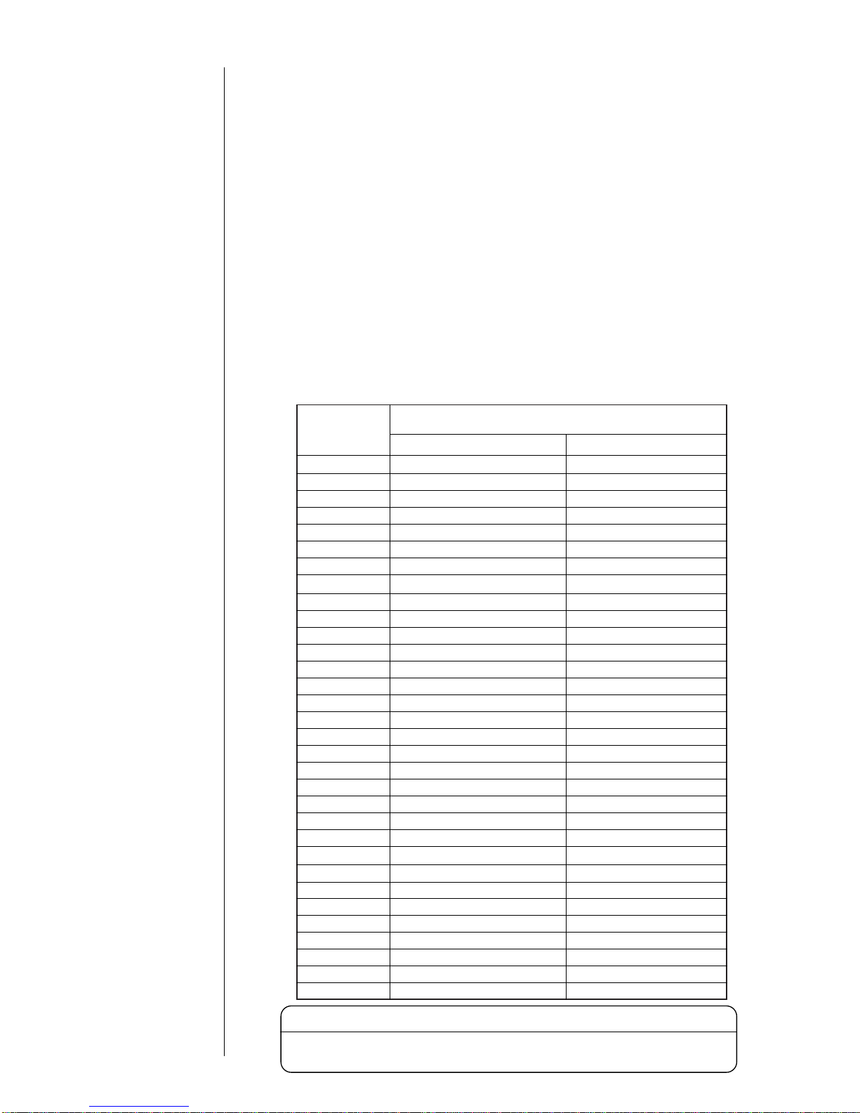
(2) Ink periodic replacement
For the replacement procedure, see Section 7.5, Ink Replacement.
¡
While the IJ printer ink circulates for operations, it reacts with atmospheric air
elements and deteriorates with time. Therefore, it needs periodic
replacement. The table below furnishes a guide for determining the proper
replacement intervals. However, since the proper replacement intervals vary
with the printer operating environmental conditions (temperature, humidity,
dust, etc.), determine the best replacement intervals in accordance with the
obtained printings, and replace all ink within the printer with new ink.
1.2.1 Notes on ink and makeup ink
Ink type
JP-K26
Replacement intervals (operating hours or elapsed
days whichever comes earlier)
Approximate operating hours
600 to 1200 hours 6 months
600 to 1200 hours 6 months
JP-K27
600 to 1200 hours 6 months
JP-K31A 600 to 1200 hours 6 months
600 to 1200 hours 6 months
¡What is makeup ink?
The makeup ink serves
as the replenisher
that makes up for a
constituent loss due
to ink evaporation
during ink ejection.
It is also used as a
cleaning solution.
600 to 1200 hours 6 months
600 to 1200 hours 6 months
JP-Y37 600 to 1200 hours 6 months
JP-K62
JP-T64
JP-F63
JP-K65
JP-K61
JP-K67
300 to 600 hours
300 to 600 hours
600 to 1200 hours
300 to 600 hours
300 to 600 hours
200 hours
600 to 1200 hours
3 months
3 months
6 months
3 months
1 months
JP-R65 200 hours 1 months
3 months
6 months
JP-G27 600 to 1200 hours 6 months
JP-K68 300 to 600 hours
JP-K69 600 to 1200 hours
JP-K70 600 to 1200 hours 6 months
JP-T71 600 to 1200 hours 6 months
JP-K72 600 to 1200 hours 6 months
JP-T75 600 to 1200 hours 6 months
JP-R76 600 to 1200 hours 6 months
JP-K84 600 to 1200 hours 6 months
JP-K77 300 to 600 hours 3 months
JP-E78 300 to 600 hours 3 months
JP-F80 600 to 1200 hours 6 months
JP-K81 600 to 1200 hours 6 months
JP-B82 600 to 1200 hours 6 months
JP-K86 600 to 1200 hours 6 months
JP-K87 600 to 1200 hours 6 months
The ink which you can use differs with areas.
Please confirm ink which you can use to each area's distributors.
Notice

1-4 ● Usage Precautions
(3) Storage precautions
Store the ink and makeup ink in a cold dark place (0 to 20℃). (Observe this rule
no matter whether tanks are unsealed or not.)
The storage validity period is predefined for the ink and makeup ink. Begin to
use the ink/makeup ink before the "Expiration date" (「開封期限」) date arrives.
Once an ink bottle is opened, even if it is stored, the bottled ink begins to
deteriorate in the same manner as the ink in the printer. If the above-indicated
"approximate elapsed days" limit is exceeded, discard the bottle of ink. (When
an ink bottle is opened, indicate the date of opening on the bottle's label for
proper management purposes.)
The makeup ink must be added to the printer within one year after opening the
tank. Note that the makeup ink added to the printer needs no replacement.
1
2
3
4
The ink which you can use differs with areas.
Please confirm ink which you can use to each area's distributors.
Notice
¡
Do not drain the ink or makeup ink waste solution into public sewer
systems or elsewhere. Waste disposal must comply with all apropriate
regulations. Consult the appropriate regulatory agency for further
information.
WARNING
(4) Ink differences and handling precautions
Differences
1
For the part code numbers for the above inks and makeup ink, see Section 12,
"Maintenance".
Ink type
Applicable
makeup ink
Operating temperature range
65μm 40μm
JP-K26 TH-TYPE B
0 to 35℃
Inapplicable
100μm
0 to 35℃
Inapplicable
0 to 35℃
Inapplicable
0 to 35℃
Inapplicable
JP-K27 TH-TYPE A
0 to 45℃ 0 to 35℃
JP-R27 TH-TYPE A
0 to 35℃
Inapplicable
0 to 35℃
Inapplicable
0 to 35℃
Inapplicable
0 to 35℃
Inapplicable
0 to 35℃ 0 to 35℃
Inapplicable
0 to 35℃
JP-B27 TH-TYPE C
JP-G27 TH-TYPE A
JP-K28 TH-TYPE A
JP-K31A TH-TYPE E
JP-K33 TH-18
JP-Y37 TH-TYPE E
JP-K60 TH-60
JP-K61 TH-23
JP-K62 TH-18
JP-F63 TH-63
JP-T64 TH-18
JP-K65 TH-65
JP-R65 TH-65
JP-K67 TH-TYPE A
JP-K68 TH-TYPE F
JP-K69 TH-69
JP-K70 TH-70
JP-T71 TH-71
JP-K72 TH-18
JP-T75 TH-75
JP-R76 TH-76
JP-K84 TH-84
JP-K77
TH-77
JP-E78 TH-78
JP-F80
JP-K81
JP-B82
JP-K86
TH-80
TH-81
TH-82
TH-86
JP-K87 TH-18
0 to 45℃
0 to 35℃
0 to 45℃
Inapplicable
0 to 35℃
0 to 35℃
0 to 40℃
Inapplicable
0 to 35℃
Inapplicable
Inapplicable
0 to 35℃
15 to 35℃
10 to 35℃
0 to 35℃
0 to 40℃

● Usage Precautions 1-5
Handling precautions
2
a. When you use the JP-K31A, JP-K60, JP-F63, JP-K68, JP-K70, JP-T71,
JP-K77, JP-E78 or JP-K84 ink, you must complete the print head air-purge
procedure without regard to the humidity predominating in the employed
environment.
(See Section 1.2.6, "Print head air purge".)
b. (1) The JP-K31A, JP-K60, JP-K69 and JP-K84 inks employ carbon black as
the pigment.
If an excess electrostatic charge alarm is issued when no ink or makeup
ink is on the print head surface and ink drops are properly generated, it is
conceivable that carbon black may be deposited on the print head
surface.
This may have been incurred by creeping leakage on the deflection
electrode mounting surface. In such an instance, remove the deflection
electrode from the printer head and wipe the entire mounting surface
clean.
(2) The JP-K31A, JP-K60, JP-K69 and JP-K84 inks employ carbon black as
the pigment.
Shake the ink bottle well before use.
c. The carbon black pigment of the JP-K31A may cohere depending on the
employed environment. For enhanced pigment stability, you should perform
the following maintenance programs.
¡Replace the main ink tank on a periodic basis (at intervals of about 2400
operating hours). When it needs replacement, contact your local
service personnel.
¡Replace the stainless filter within the shutoff valve (MV9, mounted on the
print head) on a periodic basis (at intervals of about 2400 operating hours).
When it needs replacement, contact your local service personnel.
d. If the dye of the JP-K60 comes into contact with the human body, it cannot
easily be removed. Exercise utmost caution to avoid skin contact with it.
e. The JP-K65, JP-R65 hardens if it is exposed to ultraviolet rays after printing.
Its hardenability varies with the printed matter material and surface condition
(roughness and presence of deposits), printed matter temperature, time
interval between printing completion and ultraviolet radiation, employed
ultraviolet radiation device, and other factors. You should confirm the ink
hardenability under the employed operating conditions.
Typical hardening conditions
Lamp type Metal halide lamp (2kW)
Lamp light emission length 250mm (80W/cm)
Radiation distance 150mm
Radiation time 15seconds
If ink sticks to the end of the nozzle, the ink stream will be bent, the nozzle
may be clogged, or printing disorder may be caused. Before ejection, apply
the makeup ink to the orifice plate to wash it.
f. If JP-F63 has been deteriorated by light (corresponding to the irradiation of
sunlight for one month or more), light emission by ultra violet rays becomes
difficult. However, this condition can be improved into a light emission enable
status by applying a regenerating liquid (type: RF-B1, code No.: 451520).
g. The JP-B27 require to replace the stainless filter within the shutoff valve
(MV9, mounted on the print head) on a periodic basis (at intervals of about
2400 operating hours). When it needs replacement, contact your local
service personnel.

h. Differences in JP-Y37 and cautions on use
The JP-Y37 ink uses organic color whose specific gravity is low for pigment.
It can be used in the same way as dye ink when periodical maintenance is
performed.
(1) Cautions during normal operation
1-6 ● Usage Precautions
Item
Ink
Ink
reservoir
Main ink
tank
Maintenance
period
When ink is
charged,
replenished or
replaced
When ink is
replaced
(or 6 months
after ink is
charged)
When ink is
replaced
(or 6 months
after ink is
charged)
Caution during maintenance
Shake the ink bottle well until all precipitated
pigment is dispersed. (See "7.3 Ink replenishment"
and "7.5 Ink replacement".)
(See "1.3 Component names and functions")
Referring to "7.5 Ink replacement", drain the ink
from ink reservoir, and check to see if there is
any sediment at the bottom of ink reservoir.
If there is any sediment, pour the makeup ink
on the sediment in ink reservoir to wash it out.
(Also wash the inside of ink reservoir with the
makeup ink.) Drain the makeup ink after
washing, and charge new ink.
1
2
(See "1.3 Component names and functions")
Check to see if there is any sediment at the
bottom of ink reservoir. (A dark yellow
substance at the bottom of tank can be judged
as sediment.)
If sediment is found and "7.16 Draining the Ink
from the Main Ink Tank" is not possible (the
flow from drain tube cannot be confirmed),
execute the long-term shutdown process,
referring to "7.15 Long-term Shutdown", and
remove the sediment.
If the sediment cannot be removed, replace the
main ink tank. When replacing the main ink
tank, contact your local distributor.
1
2
3
(2) Caution when continuously injecting ink:
When ink is continuously injected, it even once a day for more than a month,
perform the circulation of ink without interruption at least once a month,
referring to "7. Circulation System Operating and Adjustment Procedures", in
order to prevent sediment of ink accumulating in print head cable tube.(No
printing can be performed while "Ink Circulation" is being executed.)
(3) Other cautions
If the nozzle or gutter is dried by mistake and ink is stuck to it, and it cannot
be recovered by solvent washing with makeup ink, immerse nozzle or gutter
in household detergent of approx. 0.5% and wash in an ultrasonic washer
for approx. 10 minutes. The stuck ink will be loosened and can then be
removed.
When using the printer in an environment where the humidity is more than
85%, the amount of sediment may increase. Perform air purge (see "1.2.6
Print head air purge").
1
2

● Usage Precautions 1-7
i. JP-T71 and JP-T75 will change color if retorting processing (heating with hot
water or steam) is done after printing. Since water is necessary for change of
color, the change will not occur if heating is done with hot air. Be sure to perform
ex ante evaluation for color changeability. Degree of change will vary depending
on the conditions of printing matter, retorting device or retort processing. Confirm
the change in the condition being used.
(1) Items to be checked befor using:
Change of color
CAUTION
(1)Change of color is caused by element seeping as a result of boiling or
use of condensed steam.
(2)Water is necessary for change of color. No change of color will occur if
heating is done with hot air.
(3)Reference condition for change of color by heating with steam is 120℃
for 20 minutes. However, if stream of steam in retorting device is not
sufficient, change of color may not occur, or color may change
unevenly. And the degree of change may vary depending on the
position inside the device, retort food, canned content or contents of
printed matter.
(4)Reference condition for change of color by heating with boiled water is
100 ℃ for 20 minutes. However, seeped dye may stain, color blur may
occur or poor change of color may occur, due to uneven temperature
inside retorting device, flow or retention of hot water on printed surface.
And the degree of change may vary depending on the position inside
the device, retort food, canned content, surface tempurature of can or
contents of printed matter.
(5)Change of color does not guarantee that sterilization has been perfectly
performed, nor does the case when color does not change always
indicate that heating has not been performed.
(6)Change of color tone will vary depending on material of printed matter,
shape, surface condition and hue. Especially, when printing is done
with dark color, change may not be clearly indicated.
(1)Change of color is caused by seeping of dye. So, in cause before
change of color, the elution test standard for appliance and container
specified by food hygiene law will not be satisfied. However, the
standard will be satisfied after change of color: If used for food
container, be sure to confirm change of color. (JP-T71)
Boiling,
condensed water
j. Caution of JP-K77, JP-K81 and JP-K86
(1) When handling ink or makeup, take enough care not to spill ink or makeup.
If you spill any ink or makeup by accident, wipe it off completely and promptly
with wiping paper or something similar.
Be sure to close the maintenance cover after the portion where you wiped is
completely dry, because vapors of ink or makeup staying inside the printer
may catch on or cause a fire.
(2) Never remodel the printer.
(3) Never let the printer run is case the cooling fan is not working.
(4) Acetone is used as solvent for JP-K77, JP-K81 and JP-K86. Acetone has
characteristics of high vapor pressure (evaporable) compared with MEK, so
take care to with the following:
・ Reference period for long-term shutdown will be shorter. Operate printer
within the reference period periodically, or perform maintenance work for
long-term shutdown if shut-down time exceeds reference period.
If the printer is shut down longer than reference time, re-start may not be
possible due to settling of remaining ink component.
K. Caution of JP-E78
(1) If printed mark is boiled or soaked in water, printed characters may fade.
(2) Do not charge JP-E78 to a printer in which any other type of ink has been
used: Ink components may mix before printing.

1-8 ● Usage Precautions
In the case where the operation of the IJ printer is irregular (the IJ printer is shut
down for a few weeks in a row, for instance) in conjunction with production and
so on, there is a possibility of occurrence of a problem such as no ink ejecting
when operating the printer or no recovery possible due to accretion of the ink
inside the printer.
The period of possible shutdown is different according to the temperature of the
storage as described in the table below. When you are to use the printer in such
a manner, it is necessary to operate it (eject the ink) regularly within an
estimatedperiod of possible shutdown or perform storage work for the long-term
shutdown.
(The storage work for the long-term shutdown is to drain the ink in the ink
circulation system and refill it with the makeup ink, which requires a specific
operation on a restart. See "7.15 Long-term shutdown" for details.)
Moreover, in the case of operating it regularly, note that the time necessary for
operating it once is different according to the ink to be used and ambient
temperature of the place for the operation. (It is different depending on major
components of a solvent of the ink.)
1.2.2 IJ printer long-term shutdown
Storage temperature
Estimated term of
*
1
*3
Operating time
possible shutdown per operation
*
2
0 ≦T≦ 35 C 3 weeks 10 days 1 to 4 hours
35 < T ≦40 C 2 weeks 7 days 1 hour
40 < T ≦45 C 1 week 5 days 1 hour
*1: Maximum period possible to be continuously shut down without operation.
It is necessary to operate it at least once during this period.
*2: The values in the table indicate the case of an MEK-based ink.
See "1.2.5 Cautions on operating time when printer is in service" for the case of
an ethanol-based ink.
*3: JP-K77, JP-K81 and JP-K86 ink. See "1.2.1(4) j Caution of JP-K77, JP-K81 and
JP-K86".
Even if the treatment for long-term shutdown has been performed,
restart may not succeed due to accretion of ink components. Ask your
serviceman for restart whenever possible.
(In cases where temperature in the storage place is high [30℃ or
higher], or shutdown period has exceeded six months, be sure to ask
your serviceman for restart.)
CAUTION

● Usage Precautions 1-9
After cleaning, thoroughly wipe the print head with wiping paper and allow
it to dry.
¡
It is necessary to wipe and dry the nozzle, charging electrode, deflecting
electrode, mounting base and fringe of the gutter.
¡
While the print head is wet, do not orient its end upward.
¡
If you use the JP-K60, JP-F63,JP-K68, JP-E78 ink,you must allow the
printhead to dry firmly before running because the ink is not easy to dry.
Never immerse the print head in the makeup ink.
2
3
Cleaning with the makeup ink should be limited to the end of the print head.
To clean the end of the print head with the makeup ink, orient the end of the
print head downward.
1
1.2.3 Print head cleaning
Nozzle
Do not pour the
makeup ink over
this section.
Cleaning range
Deflecting
electrode
Gutter
Do not pour the
makeup ink over
this section.
Charging
electrode
Wipe the print head clean with
wiping paper dampened with the
makeup ink.
When a print error or
emergency stop
occurs, refer to 8. "If a
Warning Condition/
Fault Occurs".
Regarding cleaning at
a shutdown, refer to 2.2
"Shutdown".
The stain due to ink
splashes can be
removed effectively by
performing air purge for
the print head. Refer to
1.2.6 "Print head air
purge".

1-10 ● Usage Precautions
When printing is frequently performed or an space between the print material and the
print head is small, ink splashes may stain the end of the print head and the print
head cover. If this condition is left as it is, the stained status will be made worse,
resulting in a print error or emergency stop. If a print error or emergency stop
frequently occurs because of stain due to ink splashes, stop the operation that is in
progress and clean the end of the print head and the print head cover. Do this in
addition to the cleaning to be performed at the end of each daily work.
Since charging and deflecting electrodes and a gutter are provided inside the
print head, if highly conductive carbon black settles on the print head mounting
base (made of insulating material), leakage can occur between these electrodes
resulting in frequent recurrence of errors. It is, therefore, important to clean
inside the print head whenever stains are detected.
After the operation is completed, sprinkle
the makeup ink on the orifice plate, the
charging electrode, the deflecting
electrodes, the gutter and the mounting
base, and then clean them using the
cleaning pin.
Clean carbon black and makeup ink off
the parts (including the mounting base)
using paper wipers and let the parts dry
themselves in the ambient temperature.
In the case where an abnormality arises in
the operation after the above work, there
is a possibility that carbon black still
remains on the surface of the mounting
base and creepage is caused. In this
case, remove the plus deflecting
electrode, and wipe the mounting surface
clean with wipe paper to which an makeup
ink is applied.
In addition, remove the charging
electrode, and wipe the orifice plate
surface clean likewise.
5
Plus deflecting
electrode
Deflecting electrode
Gutter
Charging electrode
Pliers
Wipe it with wipe paper
and remove it.
Critical cleaning surface
(Mounting base surface)
1
2
Do not remove it
completely to
prevent a drop.
Mounting base
Cleaning bottle
Charging
electrode
Critical cleaning
surface
(Orifice plate surface)
Orifice plate
When using JP-K31A, JP-K60, JP-K69 and JP-K84 ink, the following precautions must be
observed.
4

● Usage Precautions 1-11
Press the No-cleaning stop key within the control menu.
2
Eject ink: Ejects ink while applying no deflection voltage.
No-cleaning stop: Stops ink ejection without cleaning.
Standby : Switches between the ready - for - printing state
and standby state.
Eject ink
No-cleaning
stop
Standby Cancel
=====Manual Control Menu=====
*1: Do not use the Shut down key to stop an operation more than two
successive times.
*2: If you stop an operation with the No-cleaning stop key, immediately
initiate ink ejection. If such a condition is allowed to continue, the
nozzle may become stuck with the ink, causing the ink beam to be
bent or the nozzle to be clogged.
Accordingly, apply the makeup ink to the orifice plate to wash it within
30 minutes after a stop, and then cause ink to eject once again.
Press OK .
3
The ink stop confirmation message appears.
=====Shut down Process Confirmation =====
Shutdown will stop the ink jet.
Solution To stop the ink jet, press [OK].
OK Cancel
When you press the Shut down key on the upper right-hand corner of a
screen, the printer stops after completing its automatic nozzle cleaning
sequence. If you repeatedly activate the Shut down key to stop an operation,
excessive makeup ink enters the printer, thereby thinning the ink or producing
an unduly high ink main tank solution level. If it is absolutely necessary to
repeatedly stop a printer operation, use the following procedure.
1.2.4 Shutdown (no-cleaning stop)
Press the Manual key (the Manual key is displayed commonly on all
screens).
1
Start
up
Shut
down
Manual
Comm
On/Off
Manual key
Common to all screens
Status:Ready Com=0
The procedure below works even while the startup sequence is being executed
(the Shut down key is inoperative during the startup sequence).

Caution when daily operating time is relatively long:
Since the IJ printer jets ink to the work for printing, the outside and inside of print
head cover will get dirty with accumulated ink spillage from the work, etc.
To prevent fault in printing due to dirt, periodically check the head cover, and
claen as required.
1-12 ● Usage Precautions
1.2.5 Cautions on operating time when printer is in service
Caution when daily operating time is relatively short:
If you frequently perform the shutdown procedure,excessive makeup ink enters the
printer,therby thinning the ink.
For the stable using,you must keep terms of the graphs.
01020304050
1
2
3
4
5
Ambient temperature[ C]
[hours]
【The ink contais MEK and aceton】
(JP-K27, K28, K26, R27, B27, G27, K33,
Y37, K31A, K61, K62, F63, T64, K65,
R65, K67, K69, K70, T71, K72, T75, R76,
K84, K77, F80, K81, B82, K86, K87)
0
necessary
condition
of operating
hours
01020304050
1
2
3
4
5
【The ink contains Ethanol】
(JP-K60, K68, E78)
0
[hours]
necessary
condition
of operating
hours
Ambient temperature[ C]
*1. Example.
If you use JP-K67 ink at 20℃,the IJ printer must eject the ink for one hour or more.
*2. The makeup ink which enter in the IJ printer by automatic cleaning is evaporating
naturally, and then the ink becames initial state.
1
2
● Usage Precautions 1-13
(1) Situations requiring an air purge
When the printer is used in a highly humid place such as a beer or other
beverage can line (If you use the printer in an environment in which the
relative humidity is 85% or higher, complete the print head air-purge
procedure).
When a water drainage blow sequence is performed before printing.
When the printer is used in a place where a considerable amount of paper
powder or other dust exists.
When the printing distance is short so that the end of the print head is
splashed with ink.
When you use the JP-K31A, JP-K60, JP-F63,JP-K68, JP-K70, JP-T71,
JP-K77, JP-E78, JP-K84 ink.
5
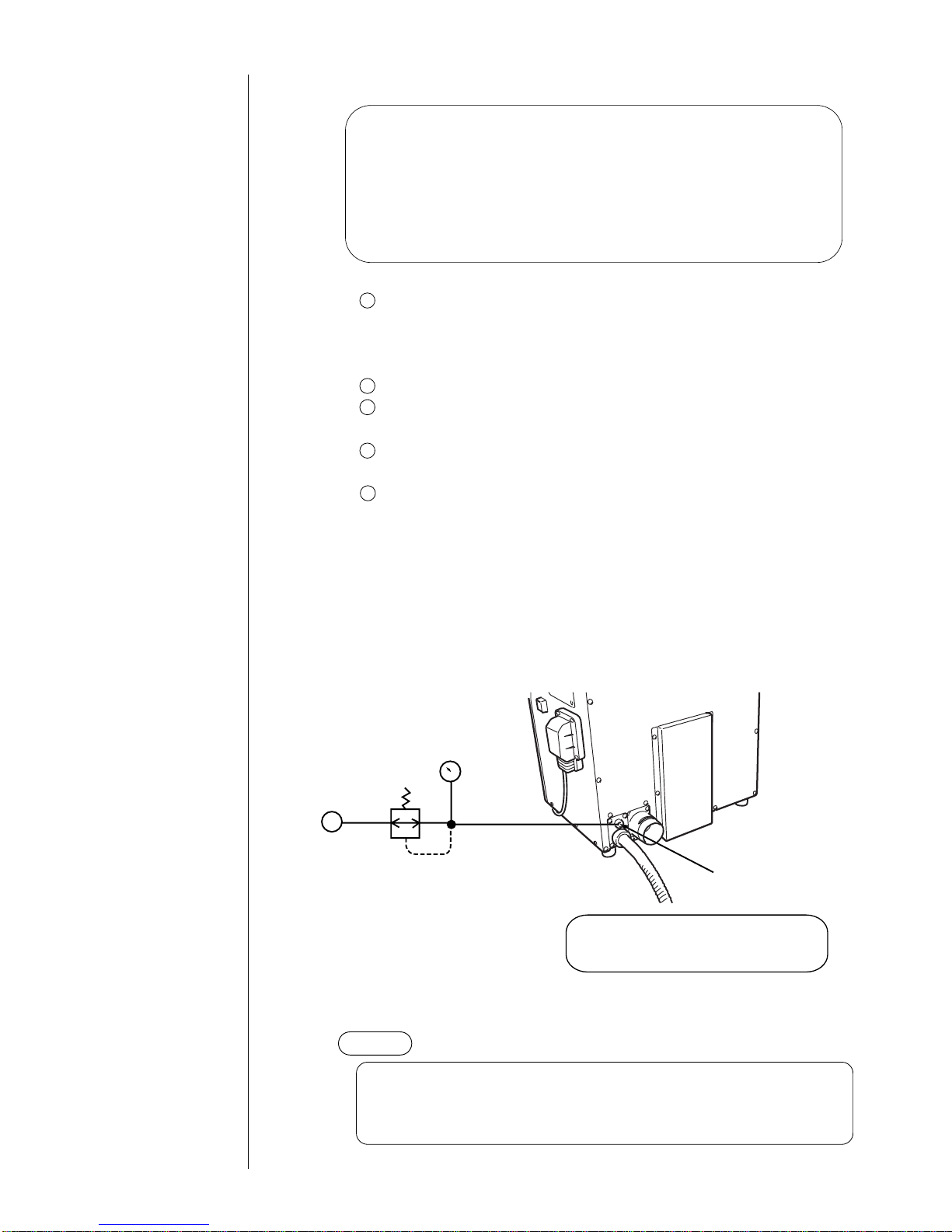
(2) Air-purging procedure
Introduce clean dry air into the print head air purge connection port (Rc 1/8 (PT
1/8)×screw) in the rear of the printer main body at a pressure of about 0.2 to 0.4
MPa. If it is possible that the employed air tanks oil or water,
turn it into clean dry air with an air filter, micro-mist separator, or the like before
introducing it into the printer main body.
NOTICE
Pressure gauge
Pressure-reducing valve
Print head
air purge connection port
Rear of
main body
Air source
(clean dry air)
Since this is a plastic type, use care to
avoid overtightening when using a metal
joint to establish a connection.
The maximum tightening torque value is 1.47 N・m.
0.2〜0.4MPa
If the air-purge amount is excessive, print irregularities may occur.
After air-purge pressure adjustment, be sure to perform a printing test to
verify the printing results.
1.2.6 Print head air purge
1
2
3
4
If the makeup ink remains in the electrode section after cleaning or if
you use the IJ printer at a high humidity, moisture condensation may
occur within the print head, causing leakage from the deflection
electrode section. It is also important to remember that dust or splashed
ink accumulation on the deflection electrode section may cause leakage.
Performing the following air purge procedure for the print head interior is
effective in preventing such leakage.

1-14 ● Usage Precautions
If the ink is not heated at low temerature, the IJ printer may not be able to print
satisfactorily.
When this failure happened, you must establish the excitation voltage again
according to "7.13 Excitation Setting Adjustment".
(1) If ambient temperature is under approximately 20℃, the ink is heated by heating
unit which established in print head.
If the heating carried out, the time of startup process is prolonged.
Non-heating : approximately 1.5 minutes
Heating : maximum approximately 10 minutes. (changed by ambient
temperature)
(2) If fault of heating unit happens, take care of the following items.
If fault of heating unit happens, the message of "Ink Heating too High" ,
"Heating Unit Sensor Fault" and "Ink Heating Current Fault" are displaied,
and then the IJ printer becomes to stop.
If you pushed Clear key, the IJ printer can be operated. However, the IJ
printer don't heat the ink since reset.
If "ink non-heating" state is established, the following message allways
indicates.
Push the Close key, and then contact your local distributor.
1.2.7 Heating of ink
1
2
3
===== Ink Temperature Correction Notice =====
The selected setup does not allow ink
temperature corrections to be made.
Solution Call your nearest distributor.
Close
1.2.8 Ink concentration control
===== No Ink Concentration Control =====
The current setting have made ink concentration
control unavailable.
Solution Press [Close].
Close
(1) Ink is automatically controlled to maintain optimum concentration for print.
(2) If fault occurs in the viscosity meter which is used to control ink concentration,
take care of the following points:
There are three types of faults for viscometer:
"Viscometer Temperature Sensor Fault", "Viscosity Reading Instability", and
"Viscosity Readings Out of Range".
When "Viscometer Temperature Sensor Fault" occurs, the unit will enter fault
stop.
Re-start is possible by pressing Clear key, but the setting will be changed to
status in which the ink concentration control based on the measuring result
using viscometer is not performed thereafter.
Once the setting of automatic concentration control is released, every time the
power is turned on, the following message will appear. Cancel the message by
pressing Close key, and be sure to inform nearest your local distributor.
1
2
When "Viscosity Reading Instability" or "Viscosity Readings Out of Range"
occurs, the unit will not enter fault stop, and print can be continued. However,
you should contact nearest your local distributor for inspection.
3

● Usage Precautions 1-15
1.2.9 Gutter cleaning
1.2.10 Protection Sheet for touch panel
The IJ printer collects ink not used for printing, from the gutter. At the same time, it
sucks in atmospheric gas, dust and other matter from the air. If these substances are
mixed with ink in the gutter, undissolved components by the ink or makeup ink may
stick to the gutter. If the system is run for 24 consecutive hours without automatic
cleaning, these components get accumulated gradually in the gutter. This, together
with the ink beam coming into contact with it, may cause such errors as "an error
stemming from a dirty head."
If any such component sticks to the gutter, immerse it in a solution of about 0.5%
household dish detergent and clean it for about 10 minutes with an ultrasonic cleaner.
The dirt can then be removed.
(1) Installation of Protection Sheet
Clean up stains, dirt, ink spots on the surface of the
touch panel.
Sweep the touch panel using wiping paper steeped by water or make-up ink.
*Make sure the surface of the touch panel dry.
Tear off the back-coat film of the Protection Sheet.
*Keep the back of sheet clean.
As in the drawing, insert the touch panel protection sheet by two points on
the underside into the IJ printer proper, and affix it to the touch panel with the
fold facing up.
(See figure)
(2) Suggestion for good use
● Do not splash ink and make-up ink on the touch panel.
Sweep immediately when sticking.
● If touch panel protection sheet is not attached correctly, key operation may not be
possible.
Insert these points
into the between
operation-panel
and touch panel.
Turn-up parts front side
Spare parts No. : 451593
(3 sheet set)
1
2
3

1-16 ● Component Names and Functions
1.3 Component Names and Functions
1.3.1 External views
Power switch
Push ON-push OFF
altanative.
Maintenance cover
Opened/closed for ink
replacement and other
maintenance purposes.
Handle
Print head
This section performs printing.
Operating status indicator lamps
Displays "Ready", "Fault" and "Warning"
Connection tube (4m)
Power lamp
Various signals intakes
See "1.5 Connection
of signals."
Handle
Turn it by 90 degrees to open
and close it.
Air-purge connection port
See Section 1.2.6, Print
head air purge.
Exhaust duct connection port

● Component Names and Functions 1-17
1.3.2 Main body internal parts arrangement
Ink reservoir
Ink filter
Makeup ink reservoir
Maintenance cover
Various signals connecting portion
Operation panel cover
Main ink tank

1-18 ● Component Names and Functions
1.3.3 Print head
Print head cover lock thumbscrew
Nozzle
Minus deflection electrode
Plus deflection electrode
Gutter
Charge electrode

● Installing Precautions 1-19
(4) The IJ printer main body must be installed with alevelness
error of not over ±1°.
(5) The IJ printer main body must be electrically insulated from
the other equipment
(conveyors, packing machines,etc.), photoelectric switches,
and the rotary encoder.
(6) The standard distance between the printing head and the
object to be printed on is as indicated in the right-hand table.
The smaller the clearance between the print head and print
target, the smaller the character height.
(7) The IJ printer proper requires maintenance as the occasion
may demand including replenishment of ink and makeup ink and replacement of filter.
¡
Ensure that there is no flame- or arc-generating device within 5
m of the printer.
The ink and makeup ink are both flammable and may cause ignition
or fire. Flames can be generated by matches, lighters, cigarettes,
heaters, stoves, gas burners, welders, grinders, and static electricity.
Arcs may be generated from open-type relays, switches, and brush
motors. Before handling the ink and makeup ink, remove electricity
from human body, the peripheral equipment, and so on. In the
interests of safety, furnish a dry-chemical fire extinguisher near the
printer.
¡
Since the ink and makeup ink contain organic solvents, install
the printer at a location where adequate ventilation (air
exhaust) is provided.
1 Never install the printer in an enclosed space.
2 Connect the printer to exhaust equipment in order to prevent the
organic solvent vapor from being retained.
WARNING
CAUTION
1.4 Installing Precautions
¡
The employed ink and makeup ink contain organic solvents.
Furnish an adequate space for the ink/makeup ink handling area and
printer installation site. A space of at least 200 m
3
must be provided
per print head. Ensure that adequate ventilation is provided.
Follow all regulation in your country.
(1) Provide a clearance around the IJ printer for daily
operation, handling, and maintenance access (see the
figure at right).
(2) The print head needs to be cleaned with the makeup ink
while the printer is operated and stopped (daily
maintenance). Adopt a fixed structure in consideration
of print head cover and print head removal.
(3) Installation must be completed so that no vibration will be
applied to the IJ printer main body, print head, or print
head cable.
If they are vibrated, print quality deterioration and print
irregularity may be incurred (the maximum permissible
vibration value is 1.96m/s
2
).
IJ printer
Maintenance area
300
mm
Top view
300
mm
300mm
750mm
Distance between the printing head
and the object to be printed on
Nozzle diameter
65μm
40μm
100μm
Distance
10 to 30mm
5mm
30 to 50mm
※Leave a maintenance area
of at least 20 cm for the
upside of printer.

1-20 ● Installing Precautions
(8) If ambient humdity is 85 to90%RH, you must purge inside of print head by air.
It is necessary for dry-clean air, refulator for pressure of air and air filter.
(Quantities of the air are 1L / minutes.)
(9) When installing the print head and print head cable, comply with the following conditions.
1 When positioning the end of the print head above the printer main body installation
surface,ensure that the distance between the end of the print head and the installation
surface does not exceed 1.5 m.
2 When positioning the end of the print head below the printer main body installation
surface, ensure that the distance between the end of the print head and the
installation surface does not exceed 1 m.
Upward printing
Lateral printing
Downward printing
Print head
cable included
1m
1.5m
Print head
Print head cable
Main body installation surface
IJ printer
main body
(10) When using the printer for upward or lateral printing, ensure that the rising print head
cable upper end is positioned not more than 0.5 m above the print head.
Print head
Print head cable
Bend R
0.5m
(11) If you fixed the print head, ensure that the minimum bend radius of the print head
cable is at least 150 mm.
(12) The ink stream may bend for some reason or other (due, for instance, to dirt).
The facilities positioned in the direction of ink ejection should be partially covered as
needed to avoid ink accumulation.
(13) When connecting an exhaust duct to the printer, install a damper and adjust the wind
velocity at the intake port to 0.3 to 0.5 m/s.
(Use an anemometer for verification. If the wind velocity is too high, the makeup ink
consumption increases.)
Exhaust duct
Connect a duct to this port
(50 mm in diameter).

● Installing Precautions 1-21
(14) If you try to fix the print head with a magnetic substance (such as iron), the cover
switch will malfunction resulting in an "Cover Open" error.
This, you must only use nonmagnetic resins or metals for fixing the print head.
(15) In the case of carrying the printer proper, put in your hands from the direction of
the arrow in the drawing below.

1-22 ● Connection of signals
1.5.1 Wiring Precautions
(1) If extraneous noise enters the printer, it may abnormally operate or become defective.
For increased noised immunity, observe the following precautions when making wiring
connections.
1 Ensure that the power supply cable connected to the printer is positioned away
from the other motive power supply lines (particularly the speed control inverter
power supply line).
For best results, they should be routed within respective ducts.
2 Do not bundle the interlock wiring together with the other motive power lines.
Be sure that they are routed separately.
3 Electrically insulate the print target detector, print head, stand, and printer main
body from the other mechanical devices (conveyors, etc.).
4 Ensure that the print target detector wiring is positioned away from the other
motive power supply lines.
5 Ensure that all electrical wiring, connections and grounding comply with
applicable codes. (A dedicated ground should be provided if erratic operations
are caused by noise or the like.)
Motor power supply line
M
Conveyor drive motor
Conveyor
Print target detector
Print head
Print target
Stand
Printing stop
Ready
Printer main body
2 Interlock
wiring
1 Primary
power supply cable
5 Ground
3
4
(2) Connection to the power supply
The printer should be connected using a suitable plug and socket outlet which is
accessible and close to the equipment, so that power can be quickly disconnected.
1.5 Connection of signals

● Connection of signals 1-23
(3) Notes on welder welding current
The IJ printer operates with its ink particles electrically charged. Therefore, a signal
(weak current) ground and frame ground are connected to it.
+++
+++
Signal ground
Nozzle
Column of ink
Charge electrode
Consequently, when a large current (e.g., welder welding current) flows in from the
outside via the frame ground, it also flows to the signal ground and may damage the
printed circuit boards.
Therefore, when conducting welding operations near the IJ printer (there must be no
flame or arc within 5m of the printer), use the following method.
Insulate the main frame of the IJ printer, print head unit, and print target detector body
from the conveyor and earth ground, and provide one-point grounding for the IJ printer
ground terminal only.
When this method is employed, welding operations can be conducted even while the IJ
printer is running.
Method
Primary power
supply cable
Print head unit
Stand (optional)
To be insulated by an insulation
IJ printer main body frame
Welding precautions
E
Ink drops are charged when a voltage is
applied between the charge electrode and
ink column as indicated at left. Therefore,
the ink is always the signal ground.
Further, since the ink is connected to the
frame ground via the circulation path
retainers and the like, it is difficult to
separate the signal ground from the frame
ground.
Principles of charging
WARNING
¡
Keep flames at least 5m away from the machine.
The ink and makeup ink are both flammable. Flames
geherated by welders may cause ignition or fire. Ensure adequate
uentitation in order to not into the fire within 5m of the printer in
printing or no-printing.
In the interest of safety, fumish a dry-chemical fire extinguisher near
the printer.
1-24 ● Connection of signals
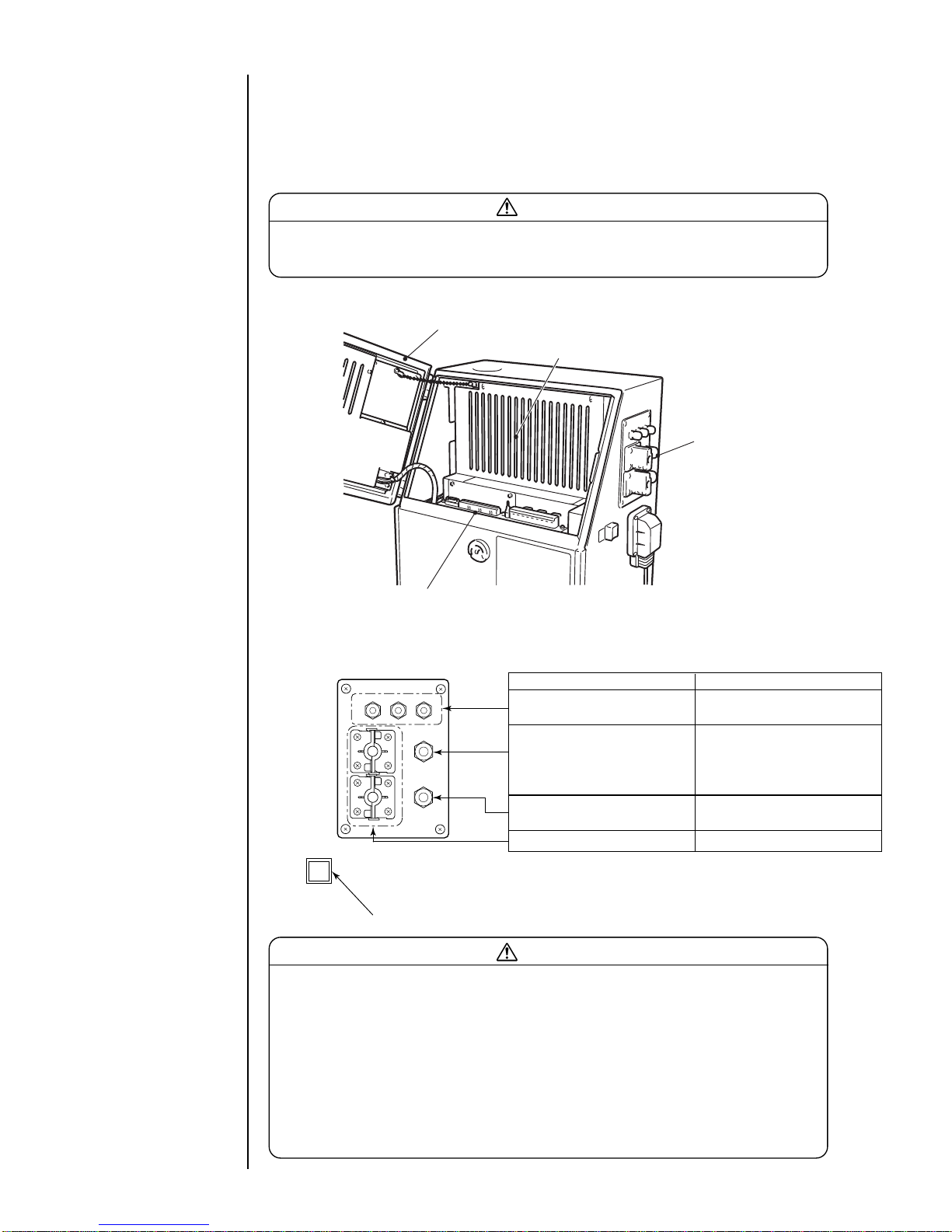
1.5.2 Overview
As for wiring of the input-output lines, open the operation panel cover and draw the
lines from the ports on the side, and connect them to the external connection terminal
blocks 1, 2 and the external communication connector inside.
Caution
Be sure to turn off the power when performing the wiring.
Keep the operation panel cover closed for normal use.
Terminal blocks 1, 2 and
communication connector
Operation panel cover
Electrical component cover
Ports
Name Cable outer diameter range
For print terget detector/
φ3.5 to 7 (M12)
encoder
For reciprocative print,
printing / print completed,
φ4.5 to 10 (M16)
stop printing, online and
remote signals
For ready, fault,
φ4.5 to 10 (M16)
warning
For external communication φ3.5 to 10
( ) indicates a tightening nut.
Power switch
Caution
Use the cables of the outer diameter range specified above. Securely tighten the
tightening nuts of the ports.
In addition, do not bundle weak-current and heavy-current signals together inside
and outside the equipment so that a weak-current signals (terminal block 1, a
connection signal to the external communication connector) will be least influenced
by noise from a heavy-current signals (a connection signal to the power supply and
the terminal block 2). In particular, the cables for the print terget detector, stop
printing signals, power supply and printable signals should never be bundled
together or wired in the same duct.
¡
Ports

● Connection of signals 1-25
¡
Layout of connectors for connection
Communication connector
External connection
terminal block 1
(TB1)
1#
17#
1#
9#
External connection
terminal block 2
(TB2)
SW1
¡
Connection to the external connection terminal block (TB1)
Pin
Name
Input/
Remarks
number output
1 Print target detector power supply Output 12 VDC; maximum: 80 mA
2 Print target detector Input
3 Print target detector ground −−
4 Printing stop Input
5 Signal ground −−
6 Encoder power supply Output 12 VDC; maximum: 80 mA
7 Encoder signal (totem pole) Input
8 Encoder signal (open collector) Input
9 Encoder ground −−
10 Deflection voltage ON/OFF Input
11 Reverse direction printing signal Input
12
Printing-in-progress/
Output Make a choice with an operating key.
printing-complete signal
13 Signal ground −−
14 Run Input
15 Reset (Clear) Input
16 Stop Input
17 Online Output
Use either one.
• Applicable cable size : AWG26 to 14 (φ0.4 to 1.6)
• Wire covering to be stripped : 9mm
Terminal block
(TB1)
Wire
Push
1
2
Insert
UL Notice
Use UL Listed wire with 30V rating or more, 60 C
rating or more and VW-1 or FT-1 notation.
The length must be 3m or less. When length is
3m or more, use the wire of CL2 or CM grade of
the NEC standard. But the power supply line
from IJP to the exterior (No. 1 and No. 6 pin of
TB1) and connection lines with equipment of a
factory (conveyer etc.) can use only the wire of
CL2 grade.

1-26 ● Connection of signals
Pin number Name Remarks
1NC
2 Ready NO
3 COM
4NC
5 Fault NO
6 COM
7NC
8 Warning NO
9 COM
¡
Connection to the external connection terminal block (TB2)
(NOTE)
NC :Normally closed
NO :Normally open
COM:Common
• Terminal specification : M4
Pin number Name Input/Output Remarks
1 (NC) − Unconnected
2 RD Input
3 SD Output
4 (NC) − Unconnected
5SG− Ground
6 (NC) − Unconnected
7 (NC) − Unconnected
8 (NC) − Unconnected
9 (NC) − Unconnected
¡
Connection to the external communication (RS-232C) connector

● Connection of signals 1-27
Cable seal block
Fixing screw
Seal Tightening nut
Cable
Cable seal block
Seal
Cable
Claw
Remove the fixing screw and
take the cable seal block off the
printer proper.
Remove the claw and divide it.
Tie the seal around the outside
of the cable as in the drawing.
Tie the seal so that there will
be no clearance between it
and the cable seal block.
Mount it on the printer proper by
using a reversed procedure.
1
2
3
4
()
Remove the tightening nut.
Put the cable through as in the
drawing.
Tighten the tightening nut.
Tighten the tightening nut
securely by using a tool.
1
2
3
)(
Notices on connecting the cable

1-28 ● Connection of signals
1.5.3-1 Ready output signal
The following describes the wiring of the signal that is outputted to the outside for
the purpose of indicating that the IJ printer is ready state.
(To prevent a print target from traveling without being printed, this signal is used,
for instance, to stop the conveyor when the IJ printer cannot perform printing.)
When this signal is connected, set the ready output switch to 3.
(See Section 1.5.4, Using the Ready Output Selector Switch).
(a) When using the NO contact (make contact)
1.5.3 Connection of various signal
(b) When using the NC contact (break contact)
For both the NO and NC contacts, the maximum capacity is 30 VAC/0.5 A or 30
VDC / 1 A. If any load having a greater capacity is used, furnish a separate
relay in between.
Further, if a motor, relay, or other inductive load is employed, a counterelectromotive force may
be generated to reduce the useful contact life. Therefore, be sure to provide
contact protection.
Typical contact protection methods are indicated below.
1 Applicable to CR system (AC, DC)
The suggested values for capacitor C and resistor R are as follows.
C: 0.5 to 1μF, no polarity
R: 0.5 to 1 Ωper 1 V
The withstanding voltages of the capacitor and resistor must be at least two times
as high as the employed voltage.
Power relay
To conveyor
Power supply
TB2
1
2
3
NC
NO
COM
Ready state
Closed
Other than
above
Open
2-3 contact
Power relay
To conveyor
Power supply
TB2
1
2
3
NC
NO
COM
Open
Closed
1-3 contact
Ready state
Other than
above
Inductive
load
R
C
TB2
1
2
3
When handling an external signal, be sure to comply with the voltage, current and
time described herein.
We cannot guarantee the operation unless it is handled correctly.

● Connection of signals 1-29
2 Diode system (applicable to DC, inapplicable to AC)
The peak inverse voltage of the employed diode must be at least 10 times as
high as the employed voltage, and its forward current must be larger than the
load current.
1.5.3-2 Fault signal output
The following describes the wiring of the signal that is outputted to the outside for the
purpose of indicating that the IJ printer is in the fault mode.
(a) When using the NO contact (make contact)
(b) When using the NC contact (break contact)
Inductive
load
TB2
1
2
3
Diode
4
5
6
NC
NO
COM
Power supply
Status indicator
lamp or the like
TB2
5-6 contact
Fault
state
Closed
Normal
state
Open
4
5
6
NC
NO
COM
Power supply
Status indicator
lamp or the like
TB2
4-6 contact
Fault
state
Closed
Normal
state
Open

1-30 ● Connection of signals
1.5.3-3 Warning signal output
The following describes the wiring of the signal that is outputted to the outside for the
purpose of indicating that the IJ printer is in the warning mode.
(a) When using the NO contact (make contact)
(b) When using the NC contact (break contact)
For both the NO and NC contacts, the maximum capacities of the fault and
warning condition outputs are 30 VAC/0.5A, or 30 VDC/1 A. If any load having a
greater capacity is used, furnish a separate relay in between.
Further, if a motor, relay, or other inductive load is employed, a counterelectromotive force may be generated to reduce the useful contact life.
Therefore, be sure to provide contact protection as suggested for the ready
output signal wiring.
7
8
9
NC
NO
COM
Power supply
Status indicator
lamp or the like
TB2
8-9 contact
Warning
state
Closed
Normal
state
Open
7
8
9
NC
NO
COM
Power supply
Status indicator
lamp or the like
TB2
7-9 contact
Warning
state
Closed
Normal
state
Open

● Connection of signals 1-31
1.5.3-4 Print target detector
(a) When a dedicated power supply is not used
If the print target detector current consumption is not more than 80 mA, no dedicated
power supply is required because adequate power can be supplied from the IJ printer
built-in power supply. In such a situation, make wiring connections and perform setup
as indicated below.
(i) Print target detector wiring method
Use a print target detector whose output is of a noncontact (transistor) type.
The best suited detector would be an amplifier-incorporated photoelectric sensor
that uses an optical beam for print target detection.
(ii) Print target detector specifications
a Output circuit
The IJ printer input circuit serves as a current-steered load for the print
target detector output circuit so that the printing start signal is entered when
the print target detector output transistor (Tr) turns ON. Ensure that the
employed output transistor (Tr) complies with the following specifications.
Withstanding voltage : 12 VDC or more
Maximum drive current : 12 mA or more (IL≒10mA)
Residual voltage : 2 V or less
Leak current : 0.1 mA or less
b Power supply specifications
Supply voltage : DC12V
Current consumption : 80 mA or less
Print target detector
TB1
+12V
Signal
GND
+12V
Signal
GND
1
2
3
When a transmission type is employed,
both the light emitter and receptor must
be connected in the same manner.
GND
Tr
GND
+12V
+12V
Signal
1
2
3
SW2-5
Print target detector IJ printer
(iii) Setup procedure
Turn ON switch SW2-5 on the EZJ95 board (terminal).
(Switch 2 is inside the cover. Do not operate it unless you have finished the
service education.)
12345678
ON
OFF
(Switch is black.)

1-32 ● Connection of signals
(b) When a dedicated power supply is used
If the print target detector current consumption is more than 80 mA, furnish a dedicated
power supply. In this instance, make wiring connections and perform setup as indicated
below.
(i) Print target detector wiring method
(ii) Setup procedure
Turn OFF switch SW2-5 on the EZJ95 board (terminal).
(Switch 2 is inside the cover. Do not operate it unless you have finished the
service education.)
Print target detector
+12V
GND GND
DC12VDedicated
power supply
+12V
TB1
+12V
Signal
GND
1
2
3
12345678
ON
OFF
(Switch is black.)
* The minimum value for the time of preparing for printing varies with the print dot matrix,
calendar setup, and count setup. Approximate time values are indicated in the table below.
One-scan time=
(vertical dot count + character width) x ink drop use percentage
excitation frequency (kHz)
N: (Integer that satisfies the equation one-scan time x N) >= a
K: 3 (ms)
Excitation frequency:68.9 (In the case of 65 μm nozzle, JP-K67)
:90.9 (In the case of 40 μm nozzle, JP-K67)
:28.1 (In the case of 100 μm nozzle, JP-K67)
(ms)
Nozzle
size
a
65μm 7
40μm 7
100μm 10
The required time is precisely calculated using the following formula. It varies with the
pre-selected vertical dot count, character width, and ink drop use percentage.
Time required for preparing for printing = (One-scan time x (N+1)) + K (ms)
Printing
Printing
3 ms minimum
3 ms minimum
OFF
ON
*Time of preparing
for printing
(Printing interval)
(Print start delay
adjustment = 0)
Print target
detection signal
Printing operation
*Time of preparing
for printing
(c
) Relationship between print target detection signal and printing operation
Nozzle Size Approximate Time
65μm or 40μm 10ms
100μm 13ms

● Connection of signals 1-33
1.5.3-5 Printing stop signal
The following describes the wiring of the signal that is entered from the outside to inhibit
printing. (Note that the ready output signal remains unchanged even if this signal is
entered from the outside.)
Input specifications
・A no-voltage contact must be used for input.
・In the case of noncontact, the following
requirements must be met.
Withstanding voltage : 12 VDC or more
Maximum drive current: 12 mA or more
Residual voltage : 2 V or less
Leak current : 0.1 mA or less
Drive method : Open collector
When the input is ON - While the IJ printer is in the ready state, it does not make prints
even if the print target detector turns ON. However, if any
printing operation is being performed, it does not come to a halt.
When the input is OFF - While the IJ printer is in the ready state, it starts making prints
upon print target detector ON.
(No-voltage contact)
A current of about
12 mA flows.
TB1
Signal
GND
4
5
Print stop signal
ON
OFF
50 ms or more
0 ms or
more
OFF
OFF
Printing
ON
ON
50 ms or more
20 ms or more
50 ms or more
Printing
[No printing]
Print start signal
Printing-inprogress signal
Printing operation
・The signal level is Low in the ON state or High in the OFF state.
・The tracking function cannot be used.
In the tracking mode, the printing stop time cannot be generated by the print stop
signal.
・In the continuous print mode, the operation is performed in accordance with the print
start signal that is generated inside the IJ printer.
In the case of following speed, the number of encoder pulses indicated below is a
standard minimum value of a printing space.
Minimum time of 1 pulse=
Necessary number of
encoder pulses
K+a
Minimum time of 1 pulse
=
x Pulse rate division factor (pulse)
(vertical dot count + character width) x ink drop use percentage
excitation frequency (kHz)
(ms)

1-34 ● Connection of signals
1.5.3-6 Rotary encoder signal
The following shows how to wire the rotary encoder and set up its switch in cases
where the product speed matching feature is used.
(a) Wiring
(i) Totem pole output
6
7
8
9
TB1
+12V
Signal
GND
+12V
Signal
GND
Rotary encoder
(ii) Open collector output
¡
The connectable rotary encoder specifications are as stated below.
Output waveform : Square wave (duty: within 50 ±25%)
Output withstanding voltage: 12 VDC or more
Load current : 12 mA or more
Leak current : 0.1 mA or less
Supply voltage : 12 VDC
Current consumption : 80 mA or less
6
7
8
9
TB1
+12V
Signal
GND
+12V
Signal
GND
Rotary encoder
+12V
Signal
GND
123 4
(b) Setup
(i) From the print specifications screen, specify whether or not to enable the product
speed matching feature.
(See Section 3.4, Setting Character Height and Character Orientation).
(ii) See the table below and set up switch SW2 on the EZJ95 board (I/O) in
accordance with the rotary encoder output type.
(Switch 2 is inside the cover. Do not operate it unless you have finished the service
education.)
SW2
Output type
Totem pole OFF ON ON ON
Open collector ON ON ON OFF
(Totem pole)
12345678
ON
OFF
(Open collector)
12345678
ON
OFF
(Switch is black.)

● Connection of signals 1-35
(iii) From the print specifications screen, set the character width as shown in the following
table (the setting varies with the ink drop use percentage).
DC dedicated power supply
+V
+V
GND
Signal
GND
Rotary encoder
GND
6
7
8
9
TB1
+12V
Signal
DC dedicated power supply
+V
+V
GND
Signal
Rotary encoder
GND
6
7
8
9
TB1
+12V
Signal
For totem pole output For open collector output
(c) Wiring for dedicated power supply use
If the rotary encoder current consumption exceeds 80 mA or a 24 VDC type rotary encoder
is used, furnish a dedicated power supply and make wiring connections as indicated below.
(d) Setup for dedicated power supply use
In the same manner as in cases where no dedicated power supply is used, refer to step (b)-
(i) above and specify whether or not to enable the product speed matching feature.
See the table below and set switch SW2 on the EZJ95 board (I/O board) in accordance with
the supply voltage (12 VDC or24 VDC). In this instance, the same setup applies to the
totem pole output and open collector output.
(Switch 2 is inside the cover. Do not operate it unless you have finished the service
education.)
1234
SW2
Supply voltage
DC12V OFF ON ON OFF
DC24V OFF OFF ON OFF
DC12V
12345678
ON
OFF
DC24V
12345678
ON
OFF
(Switch is black.)
Character width setting
002
001
000
Ink drop use percentage setting
1/1
1/2
1/3〜1/16
NOTE: For the 40μm nozzle version, an ink drop use percentage of 1/1 cannot set.
(See Section 3.4 Setting Character Height and Character Orientation.)
(e) Setting the rotary encoder pulse count and pulse rate division factor
When the rotary encoder is used, prints are made by conducting one scan after another in
accordance with the speed synchronization signal from the rotary encoder and the pulse
rate division factor (see the figure below).
To assure fixed character width, it is necessary to install the rotary encoder in such a
manner that the speed synchronization signal varies in proportion to the print target
transport speed.
Horizontal direction
dot pitch (scan)
<Printed character>
Speed synchronization
signal
When pulse rate division factor is 1/1
Horizontal direction
dot pitch (scan)
<Printed character>
Speed synchronization
signal
When pulse rate division factor is 1/3

Excitation frequency
JP-T71
JP-K72
1-36 ● Connection of signals
28.1kHz
68.9kHz
68.9kHz
68.9kHz
68.9kHz
68.9kHz
68.9kHz
68.9kHz
68.9kHz
68.9kHz
68.9kHz
Ink Type
JP-K26
JP-B27
JP-G27
JP-K31A
68.9kHz
68.9kHz
68.9kHz
JP-K27
JP-R27
JP-K33
68.9kHz
68.9kHz 90.9kHz
74.0kHz
90.9kHz
JP-Y37 68.9kHz
68.9kHz
¡
The printing scan count maximum value is dependent on the printed character width
and conveyor maximum speed and calculated using the following equation.
Substitute the nozzle diameter suited for the model you are using for item d.
Printing scan count maximum value[kHz]
1
60
horizontal dot count−1
character width[mm]−d[mm]
×
……(Equation 1)
¡
Using Equation 2, check whether the printing scan count maximum value determined
by Equation 1 can be followed by the IJ printer printing speed.
Excitation frequency(f)
(Vertical dot count + character width setting + 1) x (ink drop use percentage)
[kHz] >
¡
The excitation frequency (f) value varies with the ink type employed.
65μm Nozzle Machine 40μm Nozzle Machine 100μm Nozzle Machine
28.1kHz
28.1kHz
28.1kHz
JP-K60
JP-F63
JP-T64
JP-K65 80.0kHz
JP-R65
JP-K61
JP-K62
JP-K67
90.9kHz
90.9kHz
90.9kHz
90.9kHz
28.1kHz
JP-K28 68.9kHz
JP-K68
JP-K69
68.9kHzJP-K70
68.9kHz
68.9kHz
=conveyor maximum speed[m/min]×
printing scan count maximum value[kHz]……(Equation 2)
nozzle diameter
65μm
40μm
100μm
d
0.3
0.2
0.5
68.9kHzJP-T75
68.9kHzJP-R76
68.9kHzJP-K84
68.9kHzJP-K77
68.9kHzJP-E78
68.9kHzJP-F80
68.9kHzJP-K81
68.9kHzJP-B82
68.9kHzJP-K86
68.9kHzJP-K87

● Connection of signals 1-37
Normal Character width increased
¡
When the rotary encoder is used, you cannot change the IJ printer character width. If it
is necessary to change the character width, you have to install an appropriate device
that will permit you to vary the ratio between the conveyor speed and rotary encoder
speed synchronization signal pulse count.
¡
The number of speed synchronization signal pulses from the rotary encoder is
dependent on the printing scan count and pulse rate division factor and calculated using
the following equation.
Number of speed synchronization signal pulses[kHz]
=
……(Equation 3)
The pulse rate division factor (l/n) must be set up from the print specifications screen.
(See Section 3.4, Setting Character Height and Character Orientation).
¡
If the calculation result derived from Equation 2 is smaller than the printing scan count
maximum value (Equation 1), the product speed matching feature does not work
normally so that the character width is increased. In such an instance, lower the
conveyor maximum speed as needed so that the printing scan count maximum value is
smaller than the calculation result of Equation 2.
printing scan count[kHz]
pulse rate division factor (1/n)
10 μs min.(f=100 kHz max)
t 2
OFF
ON
Encoder signal
t 1
Duty
t 2
t 1
×100%
=
See that the duty is between 30% and 70%.
(f) Encoder signal limitation
¡
Ink drop use percentage: This must be set up from the print specifications screen (see
Section 3.4, Setting Character Height and Character Orientation).

1-38 ● Connection of signals
1.5.3-8 Print output signal (output)
The following shows the wiring of the signal that is outputted when a printing
operation is being conducted or completed by the IJ printer.
(a) Wiring
TB1
12
13 GND
Print output
Load
¡
If a relay, solenoid, or other inductive load is employed, connect a counterelectromotive force generation prevention diode in parallel with the load.
¡
The load circuit is for DC only. It cannot be used with an AC load.
Output specifications
GND
Vd
IL
V
CE
+12V
Tr
GND
IJ printer External device
TB1
12
13
1.5.3-7 Reciprocative printing signal (input)
The following shows the connection terminal for the signal that delivers instructions for a
change in the order of characters to be printed.
When the input is OFF: Forward transport
When the input is ON: Backward transport
1 2 3 1 2 3 (The arrow indicates
the sequence of printing.)
OFF state ON state
Input specifications
・A no-voltage contact must be used for
input.
・In the case of noncontact, the following
requirements must be met.
Withstanding voltage : 12 VDC or more
Maximum drive current: 12 mA or more
Residual voltage : 2 V or less
Leak current : 0.1 mA or less
Drive method : Open collector
(No-voltage contact)
A current of about
12 mA flows.
TB1
GND
Signal
9
11
(Example)
※
100 ms min.
Reverse direction printing signal
Print object detection signal
Ensure that the interval between reciprocative printing signal
changeover (ON→OFF or OFF→ON) and print object detection
signal input is at least 100 ms.
OFF
OFF
ON
ON
Operation when
changing the
correspondence
between signal
ON/OFF and printing
direction:
(See "4.2 Setting up
User Environment")
¡
The output transistor (Tr) is of an open collector type. It operates as indicated below.
While printing is performed (printing-completed signal ON) : Tr ON
While no printing is performed (printing-completed signal OFF) : Tr OFF

● Connection of signals 1-39
1.5.3-9 Input for remote control signals
These connection terminals enter actions corresponding to the run-state operation keys
of the IJ printer (Run, Stop, fault Clear, and Deflection Voltage Control (switchover
between a standby state and a ready state), by means of external switches, contact
signals, or something similar.
(a) Input specifications
・Make inputs by no-voltage contacts.
・In the case of no-contact, use terminals that satisfy the following requirements:
Withstanding voltage: 12 VDC or more
Maximum driving current: 12 mA or more
Residual voltage: 2 V or less
Leak current: 0.1 mA or less
Driving method: Open collector
・In the case of contact signal
In the case of the chattering when contact is ON or OFF , use terminals of
2.0 ms or less.
TB1
13
16
15
14
10
(No-voltage contact)
The current applied to
the system is about
12 mA.
Signal ground
High-voltage ON/OFF
Run
Reset (Clear)
Stop
+12V
GND
The same holds true
for the other signals.
・When all input contacts are ON, the system runs in the same manner as when
the Run,
Clear, Stop, or Deflection Voltage Control key is pressed.
¡
The voltage and current used by the external device must meet the following
specifications.
IL≦20mA (V
CE:TYP0.6V, MAX2V)
The IL maximum permissible current is 50 mA.
Vd≦DC30V
(b) Changeover between printing-in-progress and printing-complete
Perform printing-in-progress/printing-complete signal changeover setup from the
user environment setup screen.
(See Section 4.2, Setting the User Environment).
(c) Signal timing
Printing operation
Printing in progress
signal
Printing-complete
signal
1 sec
OFF
ON
Printing
-complete signal
OFF
ON
Less than 1 sec
※
※The printing-complete signal turns OFF when the next
printing operation starts within an elapse of less than 1 second.
more than 1 sec

1-40 ● Connection of signals
(b-2) "High-voltage ON/OFF signal"
1 For inputting the "high-voltage ON/OFF signal" in succession, a certain OFF
duration is required. When t
2 is 10 ms or less, the OFF status is not detected and
the signal cannot be accepted.
t2
High-voltage ON/OFF signal
2 The time t3 from an input of "high-voltage ON/OFF signal" till a change of statue is
3 seconds or less. (Standby -> Print Enable)
t3
High-voltage ON/OFF signal
Print Enable signal
3 For turning on the "high-voltage ON/OFF signal", the status must be confirmed
beforehand. If the "high-voltage ON/OFF signal" is turned on by mistake during
printing, this printing, which may be in progress, is aborted and the print enable
status is switched over to the standby status.
For prevention against a print error, input a signal in the status where printing is not
in progress.
4 If you want to change the contents of print when the product speed matching
function is used and the transfer is stopped during printing, this signal permits
switching the status over to the standby status to allow you to change the contents
of print.
t4 is 100ms or less. ( Print Enable -> Standby)
t4
High-voltage ON/OFF signal
Print Enable signal
t1
Remote signal
(b) Judgement conditions
(b-1) Remote signals in general
1 The ON duration of the remote signal is 100 ms or more.
2 Don't turn on multiple remote signals at a time.
If multiple signals are turned on, they cannot be accepted.
3 In the following cases, no signal is accepted.
i The confirmation window is open.
ii The circulation control screen is opened by the maintenance function.
iii The touch screen setup screen is opened by the auxiliary function.

● Connection of signals 1-41
(b-5) "Stop signal"
1 After making sure that that the IJ printer is put into a pause by turning on the "stop
signal", turn off the power supply.
The time from turning on the "stop signal" till a pause status is about 3 minutes.
2 The time t
6 from an input of "stop signal" till a change of status is 100 ms or less.
t6
Stop signal
Print enable signal
(Cautions)
(1) When using key inputs, you must check each input. However, when inputting external
signals, the equipment executes processing in accordance with instructions of these
signals. In particular, the "operation" (operation signal) instructs an ink jet. So take
extreme care in handling this signal.
(2) When the confirmation window appears, every remote signal input is invalidated. After
closing the confirmation window, input each signal once again.
When Line monitor is displayed, all remote operation signals will be disabled.
(3) When each of the touch screen setup screen and the circulation control screens
appears, every remote operation signal input is invalidated. After displaying a different
screen, input each signal once again.
(4) When the conveyor is stopped during printing by using the rotary encoder, the remote
operation signal is valid.
(5) In the case of inputting a stop signal while the fault window is open, the ink stops with
the window remaining open.
(b-3) "Fault clear signal"
1 Input this signal when the fault signal is ON.
After inputting the signal, make sure that "Fault" has been cleared.
2 Turn on the "fault clear signal" after the lapse of 30 seconds or more after turning on
the power supply of the IJ printer.
3 The time t
5 from an input of "fault clear signal" till clearing the error is 100 ms or less.
t5
Fault clear signal
Fault signal
(b-4) "Operation signal"
1 The "operation signal" is an instruction signal that automatically causes operations to
be performed up to an ink jet.
2 If the "operation signal" is turned on during ink stop processing, it will be ignored.
3 Turn on the "operation signal" after the lapse of 30 seconds or more after turning on
the power supply of the IJ printer.
After making sure that "Fault" has been cleared, input the signal.
The time from turning on the "operation signal" till a print enable status is about 2
minutes.

1-42 ● Connection of signals
1.5.3-10 Online signal output
Connection of signals outputted to the outside when the IJ printer is online
(a) Wiring
TB1
17
13 GND
Online
Load
¡
If a relay, solenoid, or other inductive load is employed, connect a counterelectromotive force generation prevention diode in parallel with the load.
¡
The load circuit is for DC only. It cannot be used with an AC load.
Output specifications
GND
Vd
IL
V
CE
+12V
Tr
GND
IJ printer External device
TB1
17
13
¡
The output transistor (Tr) is of an open collector type. It operates as indicated below.
Online : Tr ON
Offline : Tr OFF
¡
The voltage and current used by the external device must meet the following
specifications.
IL≦20mA (V
CE:TYP0.6V, MAX2V)
The IL maximum permissible current is 50 mA.
Vd≦DC30V

● Connection of signals 1-43
1.5.3-11 External communication (RS-232C)
External equipment is connected to the IJ printer by serial communication of
RS-232C.
(a) Wiring
Attaching screw: inch screw
Substrate side connector: 9-pin D sub-connector (plug)
IJ printer
SD
Output
#3
RD Input
#2
SG
External device
RD
SD
SG
FG
#5
ransmission
Reception
Cable length: maximum 5m
Caution
¡Do not connect any signal other than #2, #3 and #5 since it is not used.
¡Do not bundle it together with heavy-current signals inside and outside the
equipment so that it will not be influenced by noise from a heavy-current signals
(a connection signal to the power supply and the terminal block 2).
¡ Use a cable which is as short as possible.
Pin number Name Input/Output Remarks
1 (NC) − Unconnected
2 RD Input
3 SD Output
4 (NC) − Unconnected
5SG− Ground
6 (NC) − Unconnected
7 (NC) − Unconnected
8 (NC) − Unconnected
9 (NC) − Unconnected

1-44 ● Connection of signals
The ready output selector switch (SW1) is used to enable or disable the ready signal
output (see under "1.5.3-1 Ready output signal").
Switch setting Ready output status
1.5.4 Using the Ready Output Selector Switch
3
2
1
SW1
When this setting is
employed, the ready output
signal is enabled. The path
between the TB2 terminals
opens or closes depending
on whether the IJ printer is
ready.
Ready state Not-ready state
1-3 contact Open 1-3 contact Closed
2-3 contact Closed 2-3 contact Open
TB
2
Ready state Not-ready state
1-3 contact Open 1-3 contact Open
TB
2
Ready state Not-ready state
2-3 contact Closed 2-3 contact Closed
TB
2
When the NO contact (make
contact) is used, the ready
output signal is disabled. The
path between TB2 terminals
1 and 3 opens and the path
between TB2 terminals 2 and
3 closes as shown in the
table at right regardless of
whether the IJ printer is
ready.
When the NC contact (break
contact) is used, the ready
output signal is disabled. The
path between the TB2
terminals opens as shown in
the table at right no matter
whether the IJ printer is
ready.
3
2
1
SW1
3
2
1
SW1

● Startup 2-1
1
2. Basic Operating Procedures
2.1 Startup
¡
The ink and makeup ink employed contains organic solvents.
When handling them, wear protective gloves and safety goggles
to avoid direct skin contact.
¡
A touch key incorporated LCD is employed. When manipulating
the keys, do not apply excessive force to them.
¡
If the system becomes inoperative, press the power switch to
OFF. When turning the power switch back ON to use the printer,
see Section 10, Emergency Procedures.
CAUTION
Press the power ON/OFF switch to turn ON the power.
》
Status:Stop Com=0
Column 1 Column 2 Column 3
[USEBY・・・・] [YY.MM.DD・・・] [・・・・・・・・・・]
[YY.MM.DD・・・] [MFGDATE・・] [・・・・・・・・・・]
[ABC・・・・・・・] [CCCC・・・・・・] [・・・・・・・・・・]
[・・・・・・・・・・] [・・・・・・・・・・] [・・・・・・・・・・]
《
USEBY
MFGDATE
ABC
11.07.07
0001
11.07.07
The current operating status is indicated
(see Section 2.3.2, Status, for details).
The printings
are described.
The print layout
is indicated.
Print description
2011.07.07 12:45
Message name[AAAAAAAAAAAA
]
StartupShut
down
Manual
Prev.
col.
Next
col.
Select
message
Save
message
Menu
Print line
setup
Edit
message
Print
format
Print
spec.
Print layout
Comm
On/Off
The following print description screen opens.
2.1.1 Starting an operation
¡
It takes about 50 seconds for the above screen to open.
¡
Verify that the print descriptions are entered.
Press.
For print description
input, see Section 3,
Editing Print Data and
Printing.

2-2 ● Startup
2
Hold wiping paper or the like against the ink ejection port in the end of
the print head. Press the Start up and Ready keys in sequence.
¡
The ink jets out of the nozzle within the print head.
¡Properly position wiping paper or the like to prevent the ejected ink from scattering.
¡Before starting an operation after 24-hour or longer printer inactivity (e.g., starting a
day's operation after a holiday), complete the print head cleaning procedure in the
same manner as for shutdown (see Section 2.2, Shutdown, and Section 1.2, Usage
Precautions).
Wiping paper or the like
Print head
The ink jet will be turned ON.
Solution To turn the ink jet ON, press [Ready].
Ready
Cancel
===== Ink Jet Startup Confirmation =====
StartupShut
down
Manual
Prev.
col.
Next
col.
Press the Start up key.
Press the Ready key.
Comm
Om/Off
Entering a run signal
executes the same
action.
(See Section 1.5.3-9,
Input for remote control
signals.)

● Startup 2-3
4
3
¡
For the subsequent operations, see Section 2.1.2, If a fault occurs at the
beginning of an operation.
¡
When the ink jets out, it may momentarily scatter and stain paper.
However, this does not indicate any abnormality at all.
Manual Control Menu
=====
Manual Control Menu
=====
Press the OK key.
Shutdown will stop the ink jet.
Solution To stop the ink jet, press [OK].
OK
Cancel
=====
Shutdown Process Confirmation
=====
StartupShut
down
Manual
Prev.
col.
Next
col.
Press the Manual key.
Eject ink: Ejects ink while applying no deflection voltage.
No-cleaning stop: Stops ink ejection without cleaning.
Eject ink
No-cleaning
stop
Cancel
Press the No-cleaning stop key.
Comm
On/Off
¡
If the ink jets out continuously, a fault exists.
Press the Manual key to display the control menu. Press the No-cleaning stop
and OK keys in sequence to stop the ink ejection operation.
Wait until the status changes from "Starting" to "Ready."
¡
If any startup fault occurs, see Section 2.1.2, If a fault occurs at the
beginning of an operation.
¡
When the temperature is low (below 20℃ or so), it takes slightly longer for
the printer to become "Ready for printing" than at a normal temperature.
Enter the print target detection signal and verify the printing results.
1234
Print target
¡
When the print target detection
signal is entered while the
printer is "Ready,"
the preselected print is made.
See Section 1.2.4,
Shutdown (no-cleaning
stop).

2-4 ● Startup
1
2.1.2 If a fault occurs at the beginning of an operation
Press the Manual key to display the control menu. Press the
No-cleaning stop and OK keys in sequence to stop the ink
ejection operation.
Manual Control Menu
=====
Manual Control Menu
=====
Press the OK key.
Shutdown will stop the ink jet.
Solution To stop the ink jet, press [OK].
OK
Cancel
=====
Shutdown Process Confirmation
=====
StartupShut
down
Manual
Prev.
col.
Next
col.
Press the Manual key.
Eject ink: Ejects ink while applying no deflection voltage.
No-cleaning stop: Stops ink ejection without cleaning.
Eject ink
No-cleaning
stop
Cancel
Press the No-cleaning stop key.
Comm
On/Off
Remove the print head cover. This requires loosening its retaining screw.
2
Pull out.
Loosen the screw.
Print head cover

● Startup 2-5
4
3
Pour the makeup ink over the orifice plate, charge electrode, deflection electrodes, gutter,
and mounting base to clean them (you should also refer to Section 1.2.3, Print head
cleaning).
Orifice plate
Charge electrode
Deflection
electrode
Mounting base
Beaker
Area to be cleaned
Cleaning bottle
Gutter
* With wiping paper, thoroughly wipe the makeup ink away from the parts
(mounting base included) surfaces, and then allow them to dry.
Perform cleaning by pouring the intensifier over the area to be cleaned.
With the print head cover left removed, press the Start up and
Ready keys in sequence.
¡
The ink jets out of the nozzle. (The status changes from "Stop" to
"Starting.")
¡
Perform an operation while the end of the print head is placed in a beaker.
The ink jet will be turned ON.
Solution To turn the ink jet ON, press [Ready].
Ready
Cancel
===== Ink Jet Startup Confirmation =====
StartupShut
down
Manual
Prev.
col.
Next
col.
Press the Start up key.
Press the Ready key.
Comm
Om/Off
Entering a run signal
executes the same
action.
(See Section 1.5.3-9,
Input for remote
control signals.)

2-6 ● Startup
8
7
6
5
Make sure that the ink stream is positioned at the center of the gutter
from the side and upper direction as shown in the following figure.
Gutter
Ink stream
The ink stream
should be positioned
at the center of the
gutter inlet.
Side direction
Upper direction
Gutter entrance diameter
If the ink stream is not positioned at the center of the gutter, perform step 1 to
stop the ink ejection operation, and then proceed as directed in Section 7.6,
Correcting a Bent Ink Stream and Clogged Nozzle.
¡
When checking the ink stream position, wear protectors (goggles and
mask).
¡
If the ink or makeup ink should enter your eyes or mouth, immediately flush
with warm or cold water and see a physician.
¡ Before ejecting the ink, ensure that there is no person in the direction of
ejection. (The end of the print head must be placed in a beaker or the like.)
WARNING
Install the print head cover.
¡If the "Cover open" fault is indicated, press the Close key.
Wait until the status changes to "Ready."
Enter the print target detection signal and verify the printing results
(See Section 2.1.1, Strating an operation).

● Startup 2-7
2.1.3 Operations for Modifying the Setting Contents
¡
You can modify the setting contents (print description, character height, excitation
voltage, etc.) in any of the states "Ready," "Standby" and "Stop."
(1) Operation in the "Ready" state
¡ Until you enter the Apply key, the setting contents on the display will not be
reflected. When you have modified the contents, check that the Apply key is
not on display and then restart printing.
¡ In case you enter a print terget signal the instant the Apply key is pressed,
fault "Print Data Changeover in Progress M" occurs.
Start
up
Shut
down
The data entered will be used in the print message.
Solution Press [OK] to accept the data.
OK
Cancel
Cancel
changes
===== Data Entry Confirmation =====
Show
cursor
1
A state with no cursor or
keyboard displayed
The cursor or keyboard is
being displayed.
Input is possible.
←→↑
↓
Keyboard
←Cursor
The changed value is not
yet reflected on printing.
←→↑
↓
Keyboard
←Cursor
When you press the
Back key to move on,
a confirmation screen
appears.
You can display or
remove the cursor or
keyboard by pressing
the Show cursor key.
The Apply key is
displayed by changing
the setting.
Changing is reflected on printing
by pressing the Apply key.
At this point, the Apply key
disappears.
2
3
Manual
Show
cursor
Manual
Apply
Back
Back
Back
Start
up
Shut
down
Comm
On/Off
Start
up
Shut
down
Comm
On/Off
Manual
Comm
On/Off
Classification Screen name
Data editing
Print line setup, Edit message, Calendar condition,
substitution rule setup, Count condition, Print format,
Printing specifications,Select message,
Save message
Ready,
Standby,
Stop
Auxiliary function
Auxiliary function
Maintenance work
Manage messages, Create user pattern,
Copy data (Memory card → Printer)
Standby,
Stop
Maintenance work User environment setup, Operation management,
Date/time setup, Communication environment setup,
Excitation V update, Password setup/update,
Password protection
Touch screen setup
Copy data (Printer → Memory card)
State in which
setting contents
are modifiable
State in which setting contents are modifiable
¡
As the Apply key appears if you modify the setting contents, be sure to press the
Apply key after you have completed modification.
Procedure: Display the cursor and keyboard ⇒ Enter a value ⇒
Reflect the value in printing
1
2
3
The Apply key appears on
the following screens.
Character input, Calendar
condition, substitution rule
setup, Count condition,
Print format, Printing
specifications, User
environment setup,
Operation management,
Communication
environment setup.

2-8 ● Startup
Manual Control Menu
Press the OK key.
Printing will be aborted.
Solution Press [OK] to abort.
OK
Cancel
=====Print Abort Confirmation=====
Manual Control Menu
Press the OK key.
The newly created print data will be printed.
Solution Press [OK] to print.
OK
Cancel
=====Print Confirmation=====
Press the Manual key.
Switching from "Ready"
state to "Standby" state
Switching from "Standby"
state to "Ready" state
The control
menu appears.
The confirmation
screen opens.
1
2
3
StartupShut
down
Manual
Prev.
col.
Next
col.
=====Manual Control Menu=====
Eject ink: Ejects ink while applying no deflection voltage.
No-cleaning stop: Stops ink ejection without cleaning.
Standby : Switches between the ready - for - printing state
and standby state.
Eject ink
No-cleaning
stop
Standby Cancel
=====Manual Control Menu=====
Eject ink: Ejects ink while applying no deflection voltage.
No-cleaning stop: Stops ink ejection without cleaning.
Ready : Switches between the ready - for - printing state
and standby state.
Eject ink
No-cleaning
stop
Cancel
Press the Standby key.
Press the Ready key.
Comm
On/Off
Ready
¡
You can abort the operation by pressing the Cancel key from either the "Manual
Control Menu" screen or the confirmation screen.
(2) Switching between "Ready" state and "Standby" state
¡
When the conveyer interlock is put in operation by the Ready output signal, be
careful not to switch to "Standby" state since it will stop the conveyer.
Entering a deflection
voltage ON/OFF signal
executes the same
action.
(See Section 1.5.3-9,
Input for remote
control signals.)
See Section 1.5.3-1,
"Ready output signal".

● Startup 2-9
Ejecting the ink using the control menu
The confirmation
screen opens.
1
Manual Control Menu
The manual control menu
appears.
2
3
StartupShut
down
Manual
Prev.
col.
Next
col.
=====Maneal Control Menu=====
Eject ink: Ejects ink while applying no deflection voltage.
No-cleaning stop: Stops ink ejection without cleaning.
Eject ink
No-cleaning
stop
Cancel
The ink jet will be turned ON.
Solution To turn the ink jet ON, press [Ready].
Ready
Cancel
=====Ink Jet Startup Confirmation=====
Press the Ready key.
Press the Eject ink key.
Press the Manual key.
Comm
On/Off
¡
You can abort the operation by pressing the Cancel key from either the
"Manual Control Menu" screen or the confirmation screen.
¡
Even if you perform the above ink ejection procedure with the print head
cover installed, the printer does become ready for printing (but goes into
the standby state).
¡
When the following setup ( 1 - 3 ) is employed, the printing method is
automatically switched to the single scan control. You should bear in mind
that the print quality varies with the employed printing method particularly
when the ink drop use percentage is 1/1 or 1/2. To determine which printing
method is currently selected, view the printing specifications screen.
1 When differing print formats are designated for some or all setup items
2 When differing line count settings are employed for some or all columns
3 The ink drop use percentage is changed to 1/5 to 1/16.
¡
Perform the following setup to make prints by the printing method of line
spacing control (interlaced).
1 Ensure that the same print format is employed for all items.
2 Ensure that the same line count setting is employed for all columns.
3 The ink drop use percentage is 1/1 to 1/4.
Perform overall column setup. The format for the first item is then
applied to all the other items so as to provide line spacing control
setup. When making a 1-line print, the single scan control
predominates even if you perform steps 1 through 3 .
Precautions to be observed when changing the printings,
print format, or print line setup data
This feature is used to eject the ink from the nozzle with no intention of
printing (for maintenance purposes only).
Press the Manual key to make prints on paper.

2-10 ● Shutdown
3
2
1
2.2 Shutdown
Press the Shut down key.
The confirmation screen then opens.
Press the OK key.
¡
Wait until the status changes from "Stopping" to "Stop."
Remove the print head cover and clean the print head.
=====Shutdown Process Confirmation=====
Shutdown will stop the ink jet.
Solution To stop the ink jet, press [OK].
OK Cancel
¡
Perform cleaning by pouring the makeup ink over the area to be cleaned. Pour
the makeup ink over the orifice plate, charge electrode, deflection
electrodes,gutter, and mounting base to clean them (you should also refer to
Section 1.2.3,Print head cleaning).
While the stop process
is being performed, the
IJ printer internally
performs the following
operations.
Shuts off the highvoltage supply.
Stops ink ejection
and switches to
makeup ink
ejection.
Cleans the nozzle,
gutter, and
recovery path.
Stops makeup ink
ejection and
relieves the
circulation path
internal pressure.
2
1
3
4
Status: Stopping Com=0
Status:Stop Com=0
StartupShut
down
Maunal
Maunal
Comm
On/Off
StartupShut
down
Comm
On/Off
Orifice plate
Charge electrode
Deflection
electrode
Mounting base
Beaker
Area to be cleaned
Cleaning bottle
Gutter
*1. With wiping paper, thoroughly wipe the makeup ink away from the parts
(mounting base included) surfaces and allow them to dry.
*2. The "nozzle rubber seal" is effective in assuring orifice plate dryness and
preventing dust buildup. For increased smoothness in later printer startup, it is
recommended that you install the "nozzle rubber seal" between the orifice plate
and charge electrode while the printer is inactive. (Refer to the next page.)
¡
Complete the ink stop process by performing the following steps. If you turn OFF
the power without performing the ink stop process, the operation management
information (ink operating time and print count) and count update will not be stored
into memory. When the count function is in use, it is necessary to set the count
update (initial value) again at the time of power ON.
Entering a stop signal
will execute the same
action.
(See Section 1.5.3-5,
"Printing stop signal.)

● Shutdown 2-11
5
Install the print head cover.
6
Press the power ON/OFF switch to turn OFF the power.
4
If the print head cover is dirty, apply the makeup ink and clean it.
* 1 Clean the portion which became dirty with a splatter on printing or a
splash on ejecting the ink.
* 2 After cleaning, wipe away the makeup ink by using wiping paper.
When wiping the inside of the cover, wipe it by holding the wiping
paper with tweezers.
2. The "nozzle rubber seal" is effective in preventing orifice plate drying and dust
accumulation. When shutting down the printer, it is recommended that you set the
nozzle rubber seal between the orifice plate and charge electrode to assure
smoothness in the next printer startup.
Usage precautions
1 When storing the nozzle rubber seal, place it in a vinyl bag or the
like to prevent it from collecting dirt and dust.
2 Before setting the nozzle rubber seal in position, be sure to clean
it with the makeup ink.
3 When installing the nozzle rubber seal, exercise care not to
deform the charge electrode.
1. To prevent nozzle orifice plate drying and dust accumulation during printer transit
and storage, a "nozzle rubber seal" has been incorporated at the factory prior to
shipment. Remove the "nozzle rubber seal" at the time of printer installation/test
run/adjustment.
Charge electrode
Orifice plate
Nozzle rubber seal
Using the nozzle rubber seal
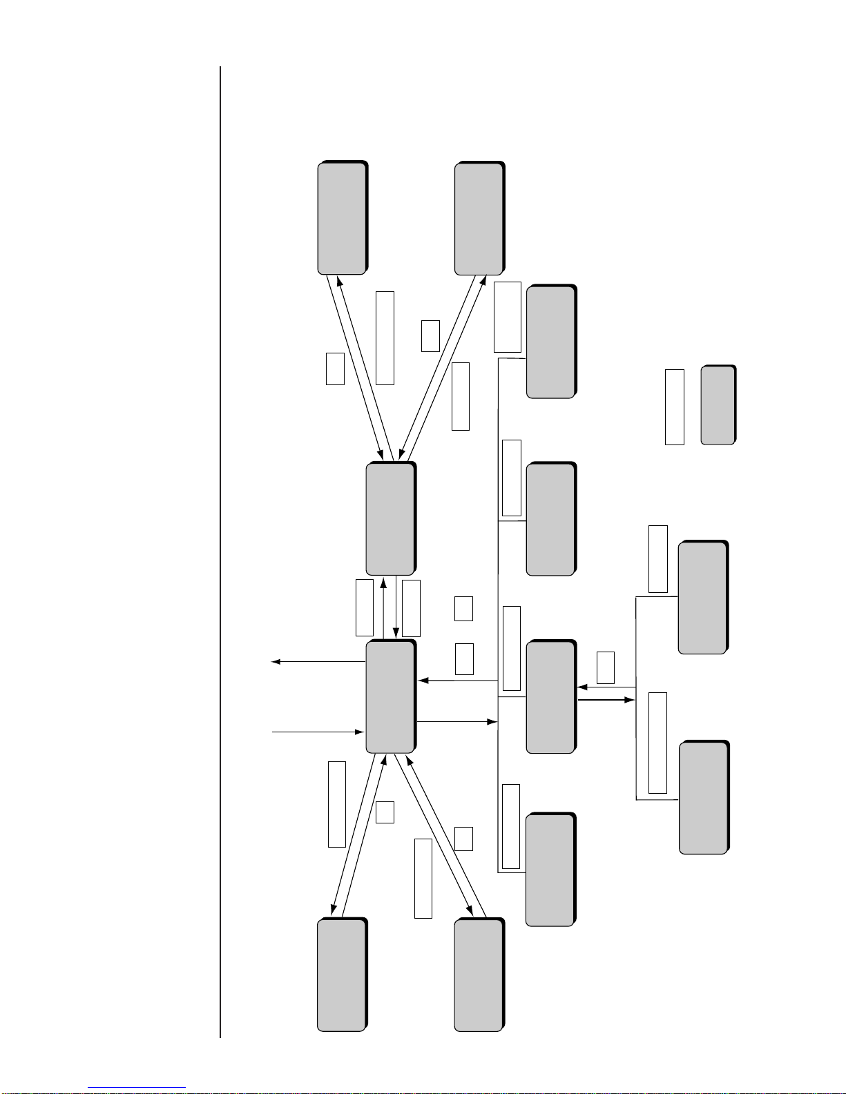
2-12 ● Operating Scheme
2.3 Operating Scheme
Save message
Calendar
conditions
YES
Printings
(editing)
Printings
(menu)
Auxiliary
functions
Edit message
Print format
Print
specifications
Menu
Power ON
Power OFF
Print line setup
Select message
Select message
Save message
Print line setup
Count conditions
Calendar conditions
Count conditions
Back
Edit message Print format
Print
specifications
Back
Maintenance
Auxiliary function
Maintenance
Back
Menu
OK
OK or
OK
Back
: Input key
: Screen name
2.3.1 Operating Scheme

● Operating Scheme 2-13
(2)The current status including the on-line/off-line (communication) state
is constantly displayed at the top of the screen.
2.3.2 Status
(1) The printer is in one of the following states.
No. State Description
1 Stop The ink is stopped. No deflection voltage is applied.
2 Standby The ink is ejected. No deflection voltage is applied.
3 Ready
The ink is ejected. The deflection voltage is applied (printing is
permitted by the sensor signal).
5
Starting
State in which the printer changes from the inactive state to
the standby state.
6
Ink heating Start up in process, with the ink being heated.
7
Drop adjust
Period during which ink particles are not properly charged in
the standby state.
8
Cover open
Period during which the nozzle head cover is open in the
standby state.
9
Service Circulation control process for maintenance task execution.
Fault
State in which a fault exists.
Status: Stop Com=0
Manual
StartupShut
down
Comm
On/Off
Status: Stop Com=0
Warning : Ink Low Warning
Manual
StartupShut
down
Comm
On/Off
(3) When a warning condition occurs, its description appears on the screen.
4

3-1 ● Editing Print Data and Printing
3. Editing Print Data and Printing
(1) Overview
¡
Input the contents to be printed from the "Print description" screen.
¡
Select the Print line setup , Print format , Edit message or Print spec.
screen from the menu and set the contents to be printed.
¡
The print image can be checked in the print layout area after input.
The contents can be
set even when the
Status shows either
"Stop", "Standby" or
"Ready".
》《
Column 1 Column 2 Column 3
[・・・・・・・・・・] [・・・・・・・・・・] [・・・・・・・・・・]
[・・・・・・・・・・] [・・・・・・・・・・] [・・・・・・・・・・]
[・・・・・・・・・・] [・・・・・・・・・・] [・・・・・・・・・・]
Print description
2011.07.07 12:45
Select
message
Message name
[
]
StartupShut
down
Manual
Menu
Print line
setup
Edit
message
Print
format
Print
spec.
Comm
On/Off
Print layout
Status: Stop Com=0
Prev.
col.
Next
col.
Print description
setting area
Print layout
indication area
Save
message
¡
At the system startup, the data that was printed last time is indicated.
Typical print description screen at the system startup
》《
USE BY
MFG DATE
05.07.07
05.09.07
Column 1 Column 2 Column 3
[USE BY ・・・・] [YY.MM.DD・ ・ ] [・・・・・・・・・・]
[YY.MM.DD・・] [MFG DATE・・] [・・・・・・・・・・]
Print description
2011.07.07 12:45
Message name[
]
Manual
Menu
Print
format
Print
spec.
Status: Ready Com=0
Prev.
col.
Next
col.
Print layout
Select
message
StartupShut
down
Print line
setup
Edit
message
Comm
On/Off
Save
message

● Editing Print Data and Printing 3-2
¡
The print description can be set up to 24 items (1 item = up to 10 characters).
》《
Column 1 Column 2 Column 3
[・・・・・・・・・・] [・・・・・・・・・・] [・・・・・・・・・・]
[・・・・・・・・・・] [・・・・・・・・・・] [・・・・・・・・・・]
[・・・・・・・・・・] [・・・・・・・・・・] [・・・・・・・・・・]
Print description
2011.07.07 12:45
Manual
Print layout
Status: Stop Com=0
Prev.
col.
Next
col.
Item
Menu
Message name
[
]
StartupShut
down
Comm
On/Off
Select
message
Print line
setup
Edit
message
Print
format
Print
spec.
Save
message
¡
Allocate each item into appropriate lines and columns to match the print
descriptions.
The lines can be set up to 4.
Column 1 Column 2 Column 3
[・・・・・・・・・・] [・・・・・・・・・・] [・・・・・・・・・・] [・・・
[・・・・・・・・・・] [・・・・・・・・・・] [・・・・・・・・・・] [・・・
[・・・・・・・・・・] [・・・・・・・・・・] [・・・・・・・・・・] [・・・
Column
Up to 4
Line
3rd line
2nd line
1st line
¡
Depending on the print description, set the "Print lines", "Character size",
"Print description" for each print item with up to 10 characters.
¡
"Print spec." is common for all print items.
¡
Select the Print line setup , Print format , Edit message , and Print spec.
screens from the menu and set them step by step.
The function, printable
lines, and character
sizes are different
depending on the
model type. For more
details, see "11.1
Printer Specifications."

3-3 ● Setting Print Lines
Performing overall setup
¡
The entered number of lines will be set for all the columns.
¡
The selectable number of lines ranges from 1 to 4.
¡
The print format is used as the print item for the first column and applied
uniformly.
¡
To set "interlaced", set it collectively for convenience sake.
¡
Printing quality is better with "interlaced" than with "single scan".
¡
If the number of vertical dots within a column exceeds the maximum number
of dots, the following print format applies.
1
Line spacing
Character size
Increased width
Inter-character space
0 dot
5×8
1 dot
1x
Bar code
None
Character size
conditions: See Section
3.2, Setting Print
Format.
¡
Characters nonconforming to the character size conditions will be
printed as spaces.
NOTICE
(1) Overview
¡
Set the number of lines to print in each column.
¡
The number of lines that can be printed in each column is up to 4.
But the line for more than 24 items cannot be set.
¡
The number of lines for each column can be set in two ways; one is to set it
for all columns at a time and the other is to set it by each column.
3.1 Setting Print Lines
Performing setup on an individual column basis
¡
The entered number of lines is set for designated columns.
¡
When the number of lines is increased, new lines are added to the
lowermost line position.
¡
When the number of lines is decreased, the lowermost lines are deleted
accordingly.
¡
No changes are acceptable if the number of print items exceeds 24.
¡
The format for the lower most line prevailing before line addition applies
to newly added lines.
¡
It becomes "single scan" if set up column by column.
¡
If the number of vertical dots within a column exceeds the maximum
number of dots, the following print format applies.
2
¡
Characters nonconforming to the character size conditions will be
printed as spaces.
NOTICE
The available functions
and printable line count
and character size vary
from one model to
another. See Section
11.1, Printer
Specifications.
Line spacing
Character size
Increased width
Inter-character space
0 dot
5×8
1 dot
1x
Bar code
None
Interlaced prints:
See Section 3.4 (1) 4
¡
Print lines can be deleted or inserted.

● Setting Print Lines 3-4
3
2
1
The "Print line setup" screen then opens.
Print line
setup type
Print line setup
2011.07.07 12:45
Manual
OK
1 line 2 lines 3 lines 4 lines
Insert
column
Delete
column
Individual column setup
Overall column setup
Cancel
Overall column setup : Sets same number of lines for all
columns.
Individual column setup : Sets number of lines for each column,
or deletes column.
Column 1 Column 2 Column 3
[・・・・・・・・・・] [・・・・・・・・・・] [・・・・・・・・・・]
[・・・・・・・・・・] [・・・・・・・・・・] [・・・・・・・・・・]
[・・・・・・・・・・] [・・・・・・・・・・] [・・・・・・・・・・]
Status: Ready Com=0
Prev.
col.
Next
col.
Message name
[
]
StartupShut
down
Comm
On/Off
(2) Operating procedure
1
Selecting a Print line setting of 4 for all columns
From the "Print description" screen, press Print line setup .
Menu
Select
message
Print line
setup
Edit
message
Print
format
Print
spec.
Save
message
Press Overall column setup .
The "Overall column setup" screen then opens.
Print line
setup type
Print line setup
2011.07.07 12:45
Manual
OK
1 line 2 lines 3 lines 4 lines
Individual column setup
Overall column setup
Cancel
Overall column setup : Sets same number of lines for all
columns.
Individual column setup : Sets number of lines for each column,
or deletes column.
Column 1 Column 2 Column 3
[・・・・・・・・・・] [・・・・・・・・・・] [・・・・・・・・・・]
[・・・・・・・・・・] [・・・・・・・・・・] [・・・・・・・・・・]
[・・・・・・・・・・] [・・・・・・・・・・] [・・・・・・・・・・]
Status: Ready Com=0
Prev.
col.
Next
col.
Message name
[
]
StartupShut
down
Comm
On/Off
Press 4 lines .
Operations for
modifying the setting
contents
(See Section 2.1.3,
Operations for
modifying the setting
contents. )
If the cursor is not
displayed, press
Show cursor .

3-5 ● Setting Print Lines
3
2
1
4 Press OK .
You are then returned to the "Print description" screen. For printings
creation purposes, the number of line is set to 4 for columns 1 to 3.
》《
Column 1 Column 2 Column 3
[・・・・・・・・・・] [・・・・・・・・・・][・・・・・・・・・・]
[・・・・・・・・・・] [・・・・・・・・・・][・・・・・・・・・・]
[・・・・・・・・・・] [・・・・・・・・・・][・・・・・・・・・・]
[・・・・・・・・・・] [・・・・・・・・・・][・・・・・・・・・・]
2011.07.07 12:45
Manual
Menu
Status: Ready Com=0
Prev.
col.
Next
col.
Select
message
Message name
[
]
StartupShut
down
Print line
setup
Edit
message
Print
format
Print
spec.
Comm
On/Off
Save
message
Print layout
Print description
2
Selecting a line count setting of 2 for the first column
From the "Print description" screen, press Print line setup .
Menu
Select
message
Print line
setup
Edit
message
Print
format
Print
spec.
Save
message
The "Print line setup" screen then opens.
Press 2 lines .
Print line
setup type
Print line setup
2011.07.07 12:45
Manual
OK
1 line 2 lines 3 lines 4 lines
Individual column setup
Overall column setup
Cancel
Insert
column
Delete
column
Overall column setup : Sets same number of lines for all
columns.
Individual column setup : Sets number of lines for each column,
or deletes column.
Column 1 Column 2 Column 3
[・・・・・・・・・・] [・・・・・・・・・・] [・・・・・・・・・・]
[・・・・・・・・・・] [・・・・・・・・・・] [・・・・・・・・・・]
[・・・・・・・・・・] [・・・・・・・・・・] [・・・・・・・・・・]
Status: Ready Com=0
Prev.
col.
Next
col.
Message name
[
]
StartupShut
down
Comm
On/Off
Press OK .
The first column is then set to 2 lines.
¡
To change the setting for another column, press Previous column or
Next column and then repeat step 2 .
If the cursor is not
displayed, press
Show cursor .

● Setting Print Format 3-6
1 to 2 lines
Character font (in dots)
(width×height in dots)
5×5
5×8or5×7
7×10
9×8 or 9×7
12×16
24×32
18×24
4 lines
machine
2 lines
machine
1 line
1 line
−
−
1 line
1 to 2 lines
1 to 2 lines
1 to 4 lines
1 to 3 lines
1 to 4lines
1 to 4lines
1 to 2 lines
1 to 2 lines
3.2 Setting Print Format
For dedicated
character varieties, see
Section 3.3.2, Printing
dedicated characters.
Number of lines
1
3
2
Setting range
0
0 to 2
0 to 2
(1) Overview
¡
The procedure for setting the line spacing, character size,
inter-character space, increased width, and bar code.
1234567890
Incre-
ment
Decre-
ment
Print format
2011.07.07 12:45
Back
Column 1 Column 2 Column 3
[・・・・・・・・・・] [・・・・・・・・・・] [・・・・・・・・・・]
[・・・・・・・・・・] [・・・・・・・・・・] [・・・・・・・・・・]
[・・・・・・・・・・] [・・・・・・・・・・] [・・・・・・・・・・]
Manual
Show
cursor
Prev.
item
Next
item
↓
↑
Status: Ready Com=0
Message name
[
]
StartupShut
down
Comm
On/Off
Line spacing [0](dots 0-2)
Character size [2](1: 5x5 2 :5x8 3 : 7x10 4 :12x16 5 :18x24 6 : 24x32 )
Inter-char. space
[1](dots 0-3)
Increased width [1](times1-9)
Bar code [0](0:none 1:C39 2:ITF 3:NW-7 4:EAN-13 5:DM 6:C128)
→
←
4
0 to 2
Line spacing
¡
The clearance to the upper line can be adjusted.
¡
Setup can be performed variously for all columns.
¡
The setting ranges are as indicated below.
Character size
¡
The character size can be set.
¡
The following character sizes are selectable.
Type
Dedicated character
Applicable character size
5×8、7×10
Katakana
5×8(5×7)、7×10、12×16、18×24
User pattern
5×5、5×8(5X7)、9×8(9X7)、7×10、
12×16、18×24、24×32
¡
If no associated character is available after a character size change, a space
is used as a substitute.
NOTICE
If the user pattern for a
newly selected
character size is not
saved, a space is used
as a substitute.
2
1
For size changeover
between 7 × 10 and 9
× 8, see Section 4.2,
Setting the User
Environment.
The available functions
and printable line count
and character sizes
vary from one model to
another. See Section
11.1, Printer
Specifications.
Special character
5×8、9×8、7×10、12×16、18×24、24×32
Arabic character
5×8、12×16、18×24、24×32
The "Arabic input" be
unable to do in "Simple
Chinese".

3-7 ● Setting Print Format
Character size
5×5
9×8 or 9×7
5×8 or 5×7
Inter-character space
0 to 3
0 to 3
0 to 7
7×10
0 to 3
12×16
24×32
18×24
0 to 4
0 to 6
0 to 8
Inter-character space
¡
The space between characters can be set.
¡
The following settings are selectable.
3
Increased width
¡
The width of characters can be magnified.
¡
The selectable magnifications are from 1 to 9.
4
Bar code
¡
The bar code type can be specified.
¡
One bar code type can be selected.
¡
The following types are selectable.
5
If the setting range is
exceeded by a
character size change,
the closest acceptable
value will be employed.
The available functions
and printable line count
and character sizes
vary from one model to
another. See Section
11.1, Printer
Specifications.
¡
Bar code type changes are simultaneously applied to all items for which bar
code setup has been cimpeleted.
¡
For DM and Code 128, number of barcodes which can be set is four.
When multiple barcodes are to be set, insert print item to which no barcode
has been set between them.
¡
For Code 39, ITF, NW-7, EAN-13, DM and Code 128 barcode can be set to
print items to which calendar or count has been set. However, barcode
cannot be set if replacement of calendar, zero suppression or characters
which cannot be used have been set. In these cases, the characters will
be replaced with invalid characters.
¡
To perform "interlaced" printing in the case of using dedicated
characters, the inter-character space of all the printing items should be 1 dot.
¡
The inter-character space of the printing items having dedicated characters
should be 1 dot.
(See Section "3.3.2 Printing dedicated characters".)
For a Inter-line method,
see "Precautions to be
observed when
changing the printings,
print format, or line
count setup data"
(See section 2.1.3,
Operation for Modifying
the Setting Contents.)
Type
Code 39
(C39)
NW-7
ITF
Available characters
0 to 9, A to Z, space, +, −, /, . (period), $, %
00 to 99
0 to 9, +, −, /, .(period), :, $
EAN-13
Data matrix
(DM)
Code128
(C128)
0 to 9
All Alphabets, numerals and symbols
(Code set B) All Alphabets, numerals and symbols, FNC1
(Code set C) 0 to 9, FNC1

● Setting Print Format 3-8
Guard
bar
Units
position
of Prefix
code
First 5 digits of
the input data
Center
bar
Check
code
Next 5 digits of
the input data
Guard
bar
Left barcode portion
Right barcode portion
5 digits 5 digits 1 digit
¡
When inserting an EAN-13 bar code, you must enter a two-digit code in the
EAN prefix area.
¡
The input data must be 10 digits. If the input data is less than 10 digits, the
"No print contents" fault will happen.
¡
The guard bar, center bar and check code are automatically added.
Notice of inserting an EAN-13 bar code
¡
When alphabet character has been set to the upper limit value, if Code set
C of Code 128 is set, all characters in the item will be replaced with invalid
characters.
¡
The start and stop codes are automatically added.
¡Set as shown below for print item to which DM is to be set:
(i) Number of lines: 1 line
(ii) Character size: 5x8, 12x16, 18x24
¡Set barcode type to "DM" on the print format screen, and select the size.
Data matrix: Type of size and maximum character number
¡Input characters within the specified digit number for print item to which
barcode has been set. If characters exceed ten digits, input across multiple
items.
¡When alphabet letters and numerals occur together,the number of characters
which can be coded will vary depending on character array.
¡When "DM8x32" is used, set item "character size 1"on the user environment
setup screen to "5x8".
Notice of DM code is used
¡With multiple line printing, only one "Code 128" can be set to the same line.
If two or more "Code 128"s are set to the same line, "Barcode incorrect 2" error will
occur.
Notice of Code 128 is used
5X8
8X32
20
10
10-19
Character size
DM size
Maximum
character
number
Numeral only
Alphabet only
Alpha-numeral
12X16
16X16
24
12
12-23
16X36
64
32
32-63
16X48
98
49
49-97
18X24
18X18
36
18
18-35
20X20
44
22
22-43
22X22
60
30
30-59
24X24
72
36
36-71

3-9 ● Setting Print Format
6
4
3
2
Press Back .
You are then returned to the "Print description" screen.
¡
To correct another column, press Previous item or Next item and
repeat steps 2 through 4 .
Press Previous item or Next item to select an item whose print
format is to be changed.
Press ↓ or ↑ to move the cursor to the setup item to be edited.
Change the value as desired with a numeric key, Decrement key,
or Increment key.
1
1234567890
Incre-
ment
Decre-
ment
Print format
2011.07.07 12:45
Back
Column 1 Column 2 Column 3
[・・・・・・・・・・] [・・・・・・・・・・][・・・・・・・・・・]
[・・・・・・・・・・] [・・・・・・・・・・][・・・・・・・・・・]
[・・・・・・・・・・] [・・・・・・・・・・][・・・・・・・・・・]
Manual
Show
cursor
Prev.
item
Next
item
↓
↑
Status: Ready Com=0
Message name[
]
StartupShut
down
Comm
On/Off
Line spacing [0](dots 0-2)
Character size [2](1: 5x5 2 :5x8 3 : 7x10 4 :12x16 5 :18x24 6 : 24x32 )
Inter-char. space
[1](dots 0-3)
Increased width [1](times 1-9)
Bar code [0](0:none 1:C39 2:ITF 3:NW-7 4:EAN-13 5:DM 6:C128)
→
←
From the "Print description" screen, press Print format .
The "Print format" screen then opens.
The on-screen cursor is positioned in the line spacing input field.
(2)Operating procedure
¡
Setting the line spacing to 1, character size to 5 × 8, inter-character
space to 1, and character width increase to 2
5
Press Apply .
Operations for
modifying the setting
contents.
(See Section 2.1.3,
Operations for
modifying the setting
contents.)
If the cursor is not
displayed, press
Show cursor .
Print format
2011.07.07 12:45
Column 1 Column 2 Column 3
[・・・・・・・・・・] [・・・・・・・・・・][・・・・・・・・・・]
[・・・・・・・・・・] [・・・・・・・・・・][・・・・・・・・・・]
[・・・・・・・・・・] [・・・・・・・・・・][・・・・・・・・・・]
Manual
Apply
Status: Ready Com=0
Message name
[
]
StartupShut
down
Comm
On/Off
Cursor will move to the
line you touched.
Selected item on the
cursor-positioned line
can be changed
by touching.

● Setting Print Format 3-10
1
1234567890
Incre-
ment
Decre-
ment
Print format
2011.07.07 12:45
Back
Column 1 Column 2 Column 3
[・・・・・・・・・・] [・・・・・・・・・・][・・・・・・・・・・]
Line spacing [0](dots 0-2)
Character size [4](1: 5x5 2 :5x8 3 : 7x10 4 :12x16 5 :18x24 6 : 24x32 )
Inter-char. space
[0](dots 0-3)
Increased width [1](times 1-9)
Bar code [1](0:none 1:C39 2:ITF 3:NW-7 4:EAN-13 5:DM 6:C128)
Manual
Show
cursor
Prev.
item
Next
item
↓
↑
Status: Ready Com=0
Message name[
]
StartupShut
down
Comm
On/Off
→
←
From the "Print description" screen, press Print format .
(3)Printing barcode
¡
After setting barcode using "Print format" screen, input contents to be printed.
¡
Character spacing has already been specified by the type of barcode:
It cannot be changed.
¡
Setting the line spacing to 0, character size to 12×16, character width
increase to 1 and barcode to code 39.
¡
Set contents to be printed to "1234567890".
3
2 Press Previous item or Next item to select an item whose print
format is to be changed.
Press ↓ or ↑ to move the cursor to the setup item to be edited.
4 Change the value as desired with a numeric key, Decrement key,
or Increment key.
5
Press Apply .
6 Press Back .
You are then returned to the "Print description" screen.
Cursor will move to the
line you touched.
Selected item on the
cursor-positioned line
can be changed
by touching.

3-11 ● Setting Print Format
7 From the "Print description" screen, press Edit message .
The "Edit message" screen then opens. Keyboard for inputting Code 39
will be displayed.
Insert
Delete
K
U
A
L
V
B
M
W
C
N
X
D
O
Y
E
P
Z
F
Q
+
G
R
−
HSI
T
/
J
Space Blank
Backspace
$%
Edit message
Column 1 Column 2 Column 3
[・・・・・・・・・・] [・・・・・・・・・・] [・・・・・・・・・・]
2011.07.07 12:45
Back
Calendar
conditions
Count
conditions
1234567890
ABC・
123・
Manual
Show
cursor
Prev.
col.
Next
col.
↓
↑
→
←
Status: Ready Com=0
Message name
[
]
StartupShut
down
Comm
On/Off
.
8 Press 1 2 3 4 5 6 7 8 9 0 .
9
Press Apply .
10
Press Back .
You are then returned to the "Print description" screen.
¡
Input numeric characters will be displayed in red on print layout screen.

● Printing Characters 3-12
3.3 Printing Characters
In addition to normal characters, calendar characters, count characters, and
dedicated characters are available.
(1) Operating procedure
¡
Entering "ABC" in the first line of the first column. The number of lines is set
to 3.
3.3.1 Printing fixed characters
》《
Column 1 Column 2 Column 3
[・・・・・・・・・・] [・・・・・・・・・・] [・・・・・・・・・・]
[・・・・・・・・・・] [・・・・・・・・・・]
[・・・・・・・・・・]
[・・・・・・・・・・]
[・・・・・・・・・・] [・・・・・・・・・・]
Print description
2011.07.07 12:45
Manual
Menu
Print layout
Status: Ready Com=0
Prev.
col.
Next
col.
Select
message
Message name
[
]
StartupShut
down
Print line
setup
Edit
message
Print
format
Print
spec.
Comm
On/Off
Save
message
Calendar character
input→See Section
3.3.3, Printing calendar
characters.
Count character input
→See Section 3.3.8,
Printing count
characters.
Dedicated character
input →See Section
3.3.2, Printing
dedicated characters.
2
1
Kana
Dedicated
User
pattern
Calendar
/count
Punct.
Insert
Delete
K
U
A
Shift
L
V
B
M
W
C
N
X
D
O
Y
E
P
Z
F
Q
+
G
R
−
H
S
×
I
T
/
J
Space Blank
Backspace
().
:
,
Edit message
Column 1 Column 2 Column 3
[・・・・・・・・・・] [・・・・・・・・・・] [・・・・・・・・・・]
[・・・・・・・・・・] [・・・・・・・・・・] [・・・・・・・・・・]
[・・・・・・・・・・] [・・・・・・・・・・] [・・・・・・・・・・]
2011.07.07 12:45
Back
Calendar
conditions
Count
conditions
1234567890
ABC・
123・
Manual
Show
cursor
Prev.
col.
Next
col.
↓
↑
→
←
Status: Ready Com=0
Message name
[
]
StartupShut
down
Comm
On/Off
Shift
Touch first column and first line.
The cursor then moves to the first line of the first column.
Press Edit message .
The Edit message screen then opens.
Operations for
modifying the setting
contents.
(See Section 2.1.3,
Operations for
modifying the setting
contents.)
If the cursor is not
displayed, press
Show cursor .
Operation when
changing the
alphanumeric keyboard
to that of QWERTY key
allocations:
(See "4.7 Touch
Screen Setup")
Keybord display has
been set to one of the
follwing settings:
"When KANA and
dedicated characters
can be input."
Kana
Dedicated
ABC・
123・
Arabic
(The "Arabic input" be
unable to do in "Simple
Chinese".)
"When special
characters can be
input."
Spe-
cial
Special2
ABC・
123・
Arabic

3-13 ● Printing Characters
5
3
Edit message
Column 1 Column 2 Column 3
[・・・・・・・・・・] [・・・・・・・・・・] [・・・・・・・・・・]
[・・・・・・・・・・] [・・・・・・・・・・] [・・・・・・・・・・]
[ABC・・・・・・・] [・・・・・・・・・・] [・・・・・・・・・・]
2011.07.07 12:45
Manual
Apply
Status: Ready Com=0
Message name
[
]
StartupShut
down
Comm
On/Off
Sequentially press A , B , and C on the keyboard.
The display then reads ABC.
Press Back .
The system then returns you to the "Print description" screen.
ABC
》《
Column 1 Column 2 Column 3
[・・・・・・・・・・] [・・・・・・・・・・] [・・・・・・・・・・]
[・・・・・・・・・・] [・・・・・・・・・・] [・・・・・・・・・・]
[ABC・・・・・・・][・・・・・・・・・・] [・・・・・・・・・・]
Print description
2011.07.07 12:45
Manual
Menu
Status: Ready Com=0
Prev.
col.
Next
col.
Select
message
Message name
[
]
StartupShut
down
Print line
setup
Edit
message
Print
format
Print
spec.
Comm
On/Off
Print layout
Save
message
4 Press Apply .
Type of alphameric
character (standard
character):
Refer to "6.4.6 Code
tables".
Notice
Part of [・・・] shows no input status (blank): Any blank part and
characters after the blank part in the item will not be printed.
<Example> In case of "ABC・・DEF・・", only ABC will be printed.

● Printing Characters 3-14
3
2
1
(1) Overview
¡
Dedicated characters are to be entered from the dedicated character keyboard.
¡
The following dedicated characters can be set.
3.3.2 Printing dedicated characters
(when KANA and dedicated characters can be input)
製造
出荷
出庫
包装
賞味
使用
有効
保証
消費
品質
保持
平成
年
月
日
以内
迄
期限
期間
¥
円
g
番号
個
Dedicated characters
are specially
predefined characters.
Character size setup
(See Section 3.2,
Setting Print Format)
(2) Operating procedure
¡
Entering "保証期限" in the third line of the first column
From the "Print description" screen, press Edit message .
The "Edit message" screen then opens.
Menu
Select
message
Print line
setup
Edit
message
Print
format
Print
spec.
Save
message
KanaArabic
Dedicated
User
pattern
Calendar
/count
Punct.
Insert
Delete
Edit message
Column 1 Column 2 Column 3
[・・・・・・・・・・] [・・・・・・・・・・] [・・・・・・・・・・]
[・・・・・・・・・・] [・・・・・・・・・・] [・・・・・・・・・・]
[・・・・・・・・・・] [・・・・・・・・・・] [・・・・・・・・・・]
2011.07.07 12:45
ABC・
123・
Status: Ready Com=0
Manual
Show
cursor
Prev.
col.
Next
col.
Message name
[
]
Start
up
Shut
down
Comm
On/Off
Press Dedicated .
The dedicated character input keyboard then appears.
製造
消費
賞味
出荷
使用
出庫
有効
包装
保証
平成
期限
¥
以内
年
期間
円
迄
月
g日番号
個品質 保持
Calendar
/count
Kana
Arabic
Dedicated
User
pattern
Punct.
Insert Delete
Space
Blank
Back-
space
ABC・
123・
It is presumed that the
internal calendar date
is July 7, 2011.
*
This chapter is only for the user of chinese characters. If you don't use chinese
characters, please skip this chapter.
If the cursor is not
displayed, press
Show cursor .
¡
Before entering dedicated characters, select a character size of 5×8 or
7 × 10. No other character size can be used to enter dedicated characters.
¡
The inter-character space of the printing items having dedicated characters
should be 1 dot.
¡
Characters are handled on an individual word basis. The whole associated
word is erased when Backspace or Delete is pressed.
[Example] If you press Delete with the cursor positioned over the first
character of "賞味期限", the resulting remaining character
string is "期限".
¡
Since the character string "製造" has a 3-character width, the display reads
"製 造".
Operations for
modifying the setting
contents
(See Section 2.1.3,
Operations for
modifying the setting
contents. )
The "Arabic input"
be unable to do in
"Simple Chinese".
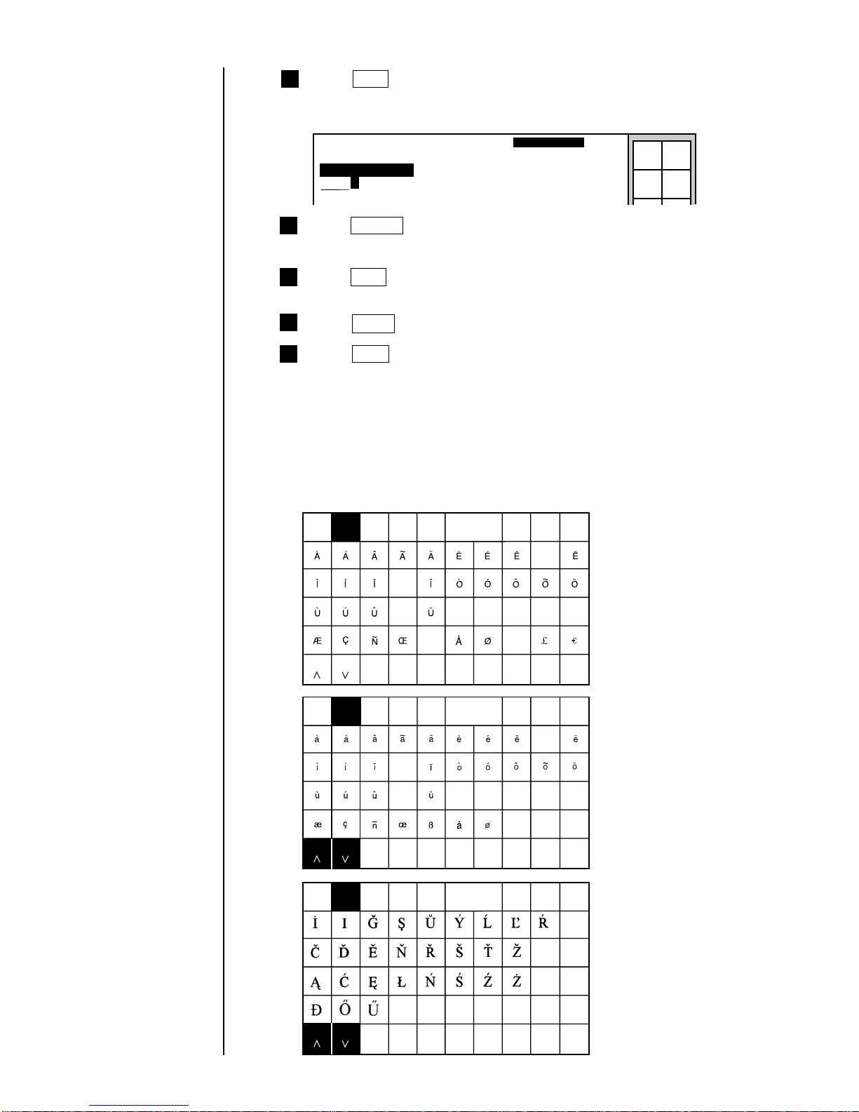
3-15 ● Printing Characters
8
6
5
4
Press Space .
A space is then displayed, and the cursor moves to the next digit position.
Edit message
Column 1 Column 2 Column 3
[保 証 ・・・・・・・] [・・・・・・・・・・] [・・・・・・・・・・]
[・・・・・・・・・・] [・・・・・・・・・・] [・・・・・・・・・・]
2011.07.07 12:45
Manual
Status: Ready Com=0
Message name[
]
StartupShut
down
Comm
On/Off
Press Back .
The system then returns you to the "Print description" screen.
Press 保証 .
The display then reads "保証" and the cursor moves to the next digit
position.
Press 期間 .
The third line of the first row then reads "保証 期間".
7
Press Apply .
(1) Overview
¡
Enter them from the special character keyboard.
¡
The characters which can be set up as special characters are as follows.
3.3.2 Printing special characters
(when special characters can be input)
Spe-
cial
User
pattern
Calendar
/count
Punct.
Insert
Delete
Space Blank
Backspace
ABC
・
123
・
Spe-
cial
User
pattern
Special2
Special2
Calendar
/count
Punct.
Insert
Delete
Space Blank
Backspace
ABC
・
123
・
Arabic
Arabic
Spe-
cial
User
pattern
Calendar
/count
Punct.
Insert
Delete
Space Blank
Backspace
ABC
・
123
・
Special2
Arabic
Shift
Shift
Shift Shift
Shift Shift

● Printing Characters 3-16
Spe-
cial
User
pattern
Special2
Calendar
/count
Punct.
Insert
Delete
Space Blank
Backspace
ABC
・
123
・
Arabic
Spe-
cial
User
pattern
Calendar
/count
Punct.
Insert
Delete
Space Blank
Backspace
ABC
・
123
・
Spe-
cial
User
pattern
Special2
Special2
Calendar
/count
Punct.
Insert
Delete
Space Blank
Backspace
ABC
・
123
・
Arabic
Arabic
Spe-
cial
User
pattern
Calendar
/count
Punct.
Insert
Delete
Space Blank
Backspace
ABC
・
123
・
Spe-
cial
User
pattern
Special2
Special2
Calendar
/count
Punct.
Insert
Delete
Space Blank
Backspace
ABC
・
123
・
Arabic
Arabic
Shift Shift
Shift Shift
Shift Shift
Shift Shift
Shift Shift
¡
The special characters cannot be entered in character size 5 x 5.

3-17 ● Printing Characters
4 Press Calendar/count .
The calendar input keyboard then appears.
Year Month Day Hour Minute
Count
Calendar
/Count
KanaArabic
Dedi-
cated
User
pattern
Punct. Insert Delete
Space
Blank
Backspace
ABC・
123・
Total
days
Second
JAN
FEB
+ − × /
( ) . : ,
Week
number
Day of
week
Shift
code
Time
count
3
2
1
(1) Overview
¡
The following procedure is used to set the year, month, day, hour, minute and
second.
¡
Entries are to be made from the calendar/count keyboard.
¡
When entries are set up as calendar characters, the year, month, day, hour,
minute and second values will be printed in accordance with calendar time
changes.
¡
Calendar characters cannot be printed in the same print item with shift code
characters or time count characters.
(2) Operating procedure
¡
Making "year," "month," and "day" entries in the third line of the second column.
3.3.3 Printing calendar characters
From the "Print description" screen, press Edit message .
The "Edit message" screen then opens.
Menu
Select
message
Print line
setup
Edit
message
Print
format
Print
spec.
Save
message
KanaArabic
Dedicated
User
pattern
Calendar
/count
Punct.
Insert
Delete
Edit message
Column 1 Column 2 Column 3
[USE BY ・・・・] [・・・・・・・・・・] [・・・・・・・・・・]
[YY.MM.DD・・] [MFG DATE・・] [・・・・・・・・・・]
[ABC・・・・・・・] [・・・・・・・・・・] [・・・・・・・・・・]
2011.07.07 12:45
ABC・
123・
Manual
Show
cursor
Prev.
col.
Next
col.
Status: Ready Com=0
Message name
[
]
StartupShut
down
Comm
On/Off
Press Next column .
The cursor then moves to the beginning of the second column.
The calendar time is
the time indicated by
the internal clock of the
IJ printer.
If the cursor is not
displayed, press
Show cursor .
Operations for
modifying the setting
contents
(See Section 2.1.3,
Operations for
modifying the setting
contents. )
Keybord display has
been set to one of the
follwing settings:
"When KANA and
dedicated characters
can be input."
Kana
Dedicated
ABC・
123・
Arabic
(The "Arabic input" be
unable to do in "Simple
Chinese".)
"When special
characters can be
input."
Spe-
cial
Special2
ABC・
123・
Arabic

● Printing Characters 3-18
7
6
5
Press . .
The "." mark then appears.
[YY.■・・・・・・]
Press Month twice.
The display then reads [YY. MM・・・・・]
If you press [Month] only once, only the last digit of the month will be printed.
Press Year .
The first press of Year prints the last digit of the year (AD) (the "y"
indication is given).
The second press of the Year prints the last two digits of the year (AD)
(the "yy" indication is given).
The fourth press of the Year prints all four digits of the year (AD) (the
"yyyy" indication is given).
The subsequent explanation applies to cases where Year is pressed
twice.
Edit message
Column 1 Column 2 Column 3
[USE BY・・・・] [YY・・・・・・・・] [・・・・・・・・・・]
[YY.MM.DD・・] [MFG DATE・・] [・・・・・・・・・・]
[ABC・・・・・・・] [・・・・・・・・・・] [・・・・・・・・・・]
2011.07.07 12:45
Manual
Apply
Status: Ready Com=0
Message name
[
]
StartupShut
down
Comm
On/Off
9 Press Day twice.
The display then reads [YY. MM. DD・・].
If you press Day only once, only the one last digit of the day will be printed.
8 Press . .
The display then reads [YY. MM・・・・・].
11
Press Back .
You are then returned to the "Print description" screen. The print image area
reads "USE BY 11.07.07".
》《
USE BY
11.07.07
MFG DATE
11.07.07
ABC
Print layout
10
Press Apply .

3-19 ● Printing Characters
Press Next column .
The cursor moves to the beginning of the second column.
3
Press ↓ .
The cursor moves to the beginning of the second line in the second
column.
4
The "Edit message" screen opens.
KanaArabic
Dedicated
User
pattern
Calendar
/count
Punct.
Insert
Delete
Edit message
Column 1 Column 2 Column 3
[USE BY・・・・] [YYMMDD・・・・] [・・・・・・・・・・]
[ABCXYZ・・・・] [・・・・・・・・・・] [・・・・・・・・・・]
2011.07.07 12:45
ABC・
123・
Manual
Show
cursor
Prev.
col.
Next
col.
Status: Ready Com=0
Message name
[
]
StartupShut
down
Comm
On/Off
2
If the cursor is not
displayed, press
Show cursor .
1
(1)Overview
¡
The following procedure is used to print the number of days that has elapsed
since January 1.
¡
Entries are to be made from the calendar/count keyboard.
¡
When entries are set up as characters indicating the number of elapsed days,
the contents of the resulting printing will be changed in accordance with the
calendar time and the current number of elapsed days.
¡
The table below shows the difference between a common year and leap year.
3.3.4 Printing the characters indicating the number of elapsed days
(2)Operating procedure
¡
Making a 3-digit entry in the second line of the second column to set the
elapsed number of days
From the "Print description" screen, press Edit message .
Menu
Select
message
Print line
setup
Edit
message
Print
format
Print
spec.
Save
message
1/1 1/2 … 2/28 2/29 3/1 … 12/31
Common year 1 2 … 59 − 60 … 365
Leap year 1 2 … 59 60 61 … 366
Operations for
modifying the setting
contents
(See Section 2.1.3,
Operations for
modifying the setting
contents. )
Cursor will move to the
line you touched.
Keybord display has
been set to one of the
follwing settings:
"When KANA and
dedicated characters
can be input."
Kana
Dedicated
ABC・
123・
Arabic
(The "Arabic input" be
unable to do in "Simple
Chinese".)
"When special
characters can be
input."
Spe-
cial
Special2
ABC・
123・
Arabic

● Printing Characters 3-20
5 Press Calendar/count .
The calendar-input keyboard appears.
Total
days
Year Month Day Hour Minute
Count
Calendar
/count
KanaArabic
Dedicated
User
pattern
Punct.
Insert Delete
Space
Blank
Backspace
ABC・
123・
Second
JAN
FEB
+ − × /
( ) . : ,
Week
number
Day of
week
Shift
code
Time
count
Press Total days .
Pressing once Total days prints the lowest digit of the number of
elapsed days (T appears on the display).
Pressing twice Total days prints the second lowest digit of the number
of elapsed days (TT appears on the display).
Pressing three times Total days prints the third lowest digit of the
number of elapsed days (TTT appears on the display).
6
Press Back .
You are returned to the "Print description" screen. The print image area
reads "188".
8
》《
USE BY
188
130204
ABCXYZ
7
Press Apply .
Keybord display has
been set to one of the
follwing settings:
"When KANA and
dedicated characters
can be input."
Kana
Dedicated
ABC・
123・
Arabic
(The "Arabic input" be
unable to do in "Simple
Chinese".)
"When special
characters can be
input."
Spe-
cial
Special2
ABC・
123・
Arabic

3-21 ● Printing Characters
The "Edit message" screen opens.
Spe-
cial
Special2
User
pattern
Calendar
/count
Punct.
Insert
Delete
K
U
A
Shift
L
V
B
M
W
C
N
X
D
O
Y
E
P
Z
F
Q
+
G
R
−
H
S
×
I
T
/
J
Space Blank
Backspace
().
:
,
Edit message
Column 1 Column 2 Column 3
[DDMMM・YYYY] [・・・・・・・・・・] [・・・・・・・・・・]
[ABCDE−XXXX] [・・・・・・・・・・] [・・・・・・・・・・]
2011.07.07 12:45
Back
Calendar
conditions
Count
conditions
1234567890
ABC・
123・
Manual
Show
cursor
Prev.
col.
Next
col.
↓
↑
→
←
Status: Ready Com=0
Message name
[
]
StartupShut
down
Comm
On/Off
Shift
1
(1)Overview
¡
Used when month is printed, indicating use of 3 alphabet characters.
¡
Entries are to be made from the calendar/count keyboard.
¡
Linked with calendar considering offset.
¡
If month is to be printed in languages other than English, it will be defined on
the "Substitution rule setup" screen for month with 3 alphabet characters.
Indication with English
3.3.5 Printing month with 3 alphabet characters
(2)Operating procedure
¡
Setting month with 3 characters in Italian
From the "Print description" screen, press Edit message .
Menu
Select
message
Print line
setup
Edit
message
Print
format
Print
spec.
Save
message
01 02 03 04 05 06
JAN FEB
MAR
APR
MAY
JUN
Keybord display has
been set to one of the
follwing settings:
"When KANA and
dedicated characters
can be input."
Kana
Dedicated
ABC・
123・
Arabic
(The "Arabic input" be
unable to do in "Simple
Chinese".)
"When special
characters can be
input."
Spe-
cial
Special2
ABC・
123・
Arabic
07 08 09 10 11 12
JUL
AUG
SEPOCT
NOV DEC
Month (numerical)
3 alphabet character

● Printing Characters 3-22
Press Calendar conditions .
The "Calendar conditions" screen then opens.
Assume that 3-digit month code has been input.
2
Press JAN,FEB,-- .
"Subst. rule setup" screen for month with 3 characters will appear.
3
1234567890
Incre-
ment
Decre-
ment
Calendar conditions
Column 1 Column 2 Column 3
[DDMMM YYYY] [・・・・・・・・・・] [・・・・・・・・・・]
[ABCDE−XXXX] [・・・・・・・・・・] [・・・・・・・・・・]
2011.07.07 12:45
Back
<Offset> <Substitution rules> <Zero-suppression>
Year [0000][0](0:Disable 1:Enable)[0](0:Disable 1:Enable)
Month
[
0000]
Day [0000][0](0:Disable 1:Enable)[0](0:Disable 1:Enable)
Hour [0000]
Minute [0000]
Substitution rules No. [01]
Manual
Show
cursor
Prev.
item
Next
item
↓
↑
→
←
Status: Ready Com=0
Substitution
rules
Message name
[
]
StartupShut
down
Comm
On/Off
JAN, FEB, --
01[JAN] 02[FEB] 03[MAR] 04[APR] 05[MAY] 06[JUN]
07[JUL] 08[AUG] 09[SEP] 10[OCT] 11[NOV] 12[DEC]
Subst. rule setup
2011.07.07 12:45
<JAN,FEB,-->
Manual
Deci-
sion
Status: Ready Com=0
StartupShut
down
Comm
On/Off
Press GEN.
4
01[GEN] 02[FEB] 03[MAR] 04[APR] 05[MAY] 06[JUN]
07[JUL] 08[AUG] 09[SEP] 10[OCT] 11[NOV] 12[DEC]
Subst. rule setup
2011.07.07 12:45
<JAN,FEB,-->
Manual
Apply
Status: Ready Com=0
StartupShut
down
Comm
On/Off
After this, input months up to December in Italian in the same
way.
5
01[GEN] 02[FEB] 03[MAR] 04[APR] 05[MAG] 06[GIU]
07[LUG] 08[AGO] 09[SET] 10[OTT] 11[NOV] 12[DIC]
Subst. rule setup
2011.07.07 12:45
<JAN,FEB,-->
Manual
Apply
Status: Ready Com=0
StartupShut
down
Comm
On/Off

3-23 ● Printing Characters
6
Press Apply .
Press Back three times.
You are returned to the "Print description" screen. The print image area
reads "07LUG 2011".
7
》《
07LUG 2011
ABCDE−XXXX
Column 1 Column 2 Column 3
[DDMMM YYYY] [・・・・・・・・・・] [・・・・・・・・・・]
[ABCDE−XXXX] [・・・・・・・・・・] [・・・・・・・・・・]
Print description
2011.07.07 12:45
Message name[
]
Manual
Menu
Print
format
Print
spec.
Status: Ready Com=0
Prev.
col.
Next
col.
Print layout
Select
message
StartupShut
down
Print line
setup
Edit
message
Comm
On/Off
Save
message

● Printing Characters 3-24
(1) Overview
¡Use this function when you want to print which week of the year the current week is.
¡Use the calendar/count keyboard to input data.
¡This function is interlocked with the calendar time that takes offset into consideration.
¡A week is defined as starting on Monday and ending on Sunday.
¡The week that includes January 4 in the year is counted as the first week.
Or: the week that includes the first Thursday in the year is counted as the first week.
¡Days at the beginning of year that are not included in the first week will be counted
as the last week of the preceding year.
3.3.6 Printing week number
December
January
Mon Tue Wen Thu Fri Sat Sun Week number
21 22 23 24 25 26 27 52
28 29 30 31 1 2 3 53
4 5 6 7 8 9 10 01
11 12 13 14 15 16 17 02
Example of counting week numbers at the end and beginning of year:
The "Edit message" screen opens.
KanaArabic
Dedicated
User
pattern
Calendar
/count
Punct.
Insert
Delete
Edit message
Column 1 Column 2 Column 3
[USE BY ・・・] [YY.MM.DD・・] [・・・・・・・・・・]
[WEEK ・・・] [・・・・・・・・・・] [・・・・・・・・・・]
2011.07.07 12:45
ABC・
123・
Manual
Show
cursor
Prev.
col.
Next
col.
Status: Ready Com=0
Message name
[
]
StartupShut
down
Comm
On/Off
Press Next column .
The cursor moves to the beginning of the second column.
2
1
(2) Operating procedure
¡
To set a 2-digit week number.
From the "Print description" screen, press Edit message .
Menu
Select
message
Print line
setup
Edit
message
Print
format
Print
spec.
Save
message
Press ↓ .
The cursor moves to the beginning of the second line in the second
column.
3
Keybord display has
been set to one of the
follwing settings:
"When KANA and
dedicated characters
can be input."
Kana
Dedicated
ABC・
123・
Arabic
(The "Arabic input" be
unable to do in "Simple
Chinese".)
"When special
characters can be
input."
Spe-
cial
Special2
ABC・
123・
Arabic

3-25 ● Printing Characters
4 Press Calendar/count .
The calendar-input keyboard appears.
Total
days
Year Month Day Hour Minute
Count
Calendar
/count
KanaArabic
Dedicated
User
pattern
Punct.
Insert Delete
Space
Blank
Backspace
ABC・
123・
Second
JAN
FEB
+ − × /
( ) . : ,
Week
number
Day of
week
Shift
code
Time
count
5
Press Week number twice.
6
Press Apply .
Press Back .
You are returned to the "Print description" screen. The print image area
reads "27".
7
》《
USE BY
27
WEEK
13.02.04
Column 1 Column 2 Column 3
[USE BY・・・] [YY.MM.DD・・] [・・・・・・・・・・]
[WEEK ・・・] [WW・・・・・・・・] [・・・・・・・・・・]
Print description
2011.07.07 12:45
Message name[
]
Manual
Menu
Print
format
Print
spec.
Status: Ready Com=0
Prev.
col.
Next
col.
Print layout
Select
message
StartupShut
down
Print line
setup
Edit
message
Comm
On/Off
Save
message
Keybord display has
been set to one of the
follwing settings:
"When KANA and
dedicated characters
can be input."
Kana
Dedicated
ABC・
123・
Arabic
(The "Arabic input" be
unable to do in "Simple
Chinese".)
"When special
characters can be
input."
Spe-
cial
Special2
ABC・
123・
Arabic

● Printing Characters 3-26
(1) Overview
¡
Use this function when expressing the day of the week as a one-digit character
and printing it.
¡
Use the calendar/count keyboard to input data.
¡
This function is interlocked with the calendar time that takes offset into consideration.
¡
A week is defined to starting on Monday and ending on Sunday.
¡
Use the "User environment setup" screen to choose the type of character for printing
calendar "day of the week".
3.3.7 Printing day of the week
A to G
1 to 7
Mon Tue Wen Thu Fri Sat Sun
1 2 3 4 5 6 7
A B C D E F G
Registered character C1 C2 C3 C4 C5 C6 C7
1
(2) Operating procedure
¡
To set 1-digit day of the week.
From the "Print description" screen, press Edit message .
The "Edit message" screen opens.
Type of character for printing calendar "day of the week":
The last 7 characters are used for registered characters.
Menu
Select
message
Print line
setup
Edit
message
Print
format
Print
spec.
Save
message
KanaArabic
Dedicated
User
pattern
Calendar
/count
Punct.
Insert
Delete
Edit message
Column 1 Column 2 Column 3
[USE BY ・・・] [YY.MM.DD・・] [・・・・・・・・・・]
[WEEK ・・・] [・・・・・・・・・・] [・・・・・・・・・・]
2011.07.07 12:45
ABC・
123・
Manual
Show
cursor
Prev.
col.
Next
col.
Status: Ready Com=0
Message name
[
]
StartupShut
down
Comm
On/Off
Press Next column .
The cursor moves to the beginning of the second column.
2
Press ↓ .
The cursor moves to the beginning of the second line in the second
column.
3
Keybord display has
been set to one of the
follwing settings:
"When KANA and
dedicated characters
can be input."
Kana
Dedicated
ABC・
123・
Arabic
(The "Arabic input" be
unable to do in "Simple
Chinese".)
"When special
characters can be
input."
Spe-
cial
Special2
ABC・
123・
Arabic
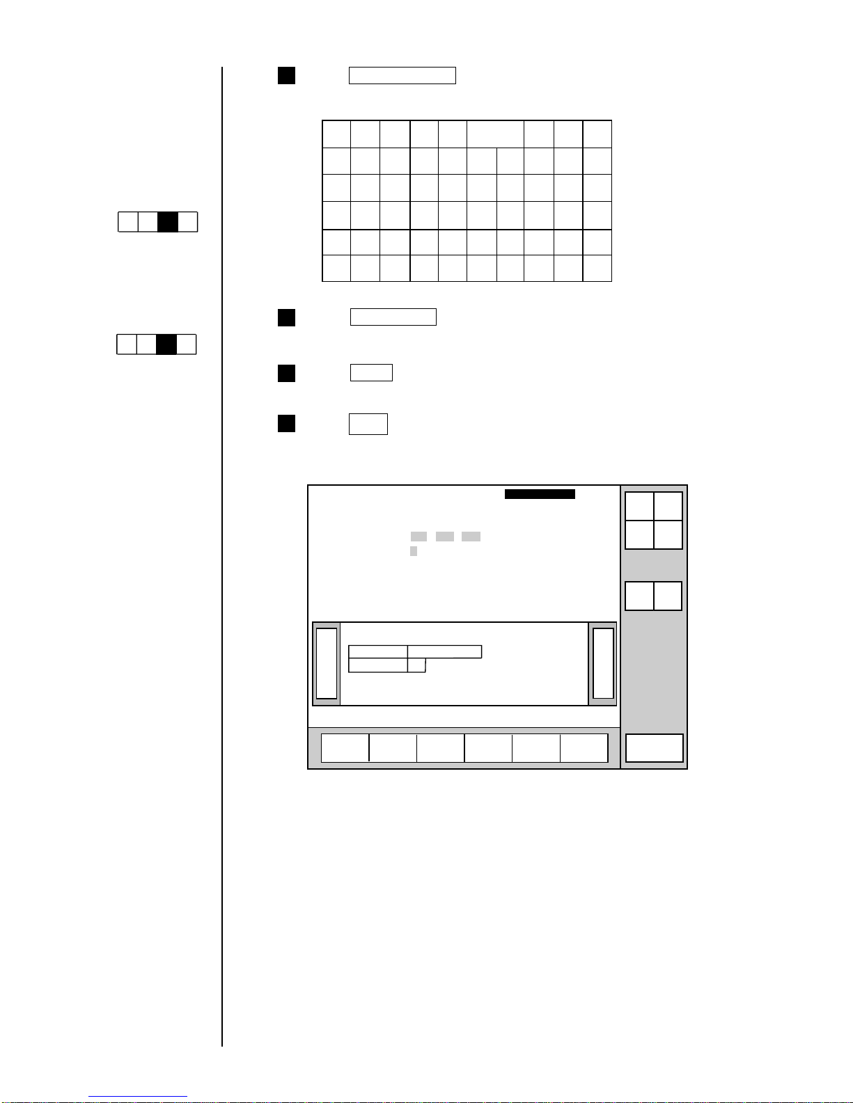
3-27 ● Printing Characters
4 Press Calendar/count .
The calendar-input keyboard appears.
Total
days
Year Month Day Hour Minute
Count
Calendar
/count
KanaArabic
Dedicated
User
pattern
Punct.
Insert Delete
Space
Blank
Backspace
ABC・
123・
Second
JAN
FEB
+ − × /
( ) . : ,
Week
number
Day of
week
Shift
code
Time
count
5
Press Day of week .
6
Press Apply .
Press Back .
You are returned to the "Print description" screen. The print image area
reads "4".
7
》《
USE BY
4
WEEK
13.02.04
Column 1 Column 2 Column 3
[USE BY・・・] [YY.MM.DD・・] [・・・・・・・・・・]
[WEEK ・・・] [7・・・・・・・・・] [・・・・・・・・・・]
Print description
2011.07.07 12:45
Message name[
]
Manual
Menu
Print
format
Print
spec.
Status: Ready Com=0
Prev.
col.
Next
col.
Print layout
Select
message
StartupShut
down
Print line
setup
Edit
message
Comm
On/Off
Save
message
Keybord display has
been set to one of the
follwing settings:
"When KANA and
dedicated characters
can be input."
Kana
Dedicated
ABC・
123・
Arabic
(The "Arabic input" be
unable to do in "Simple
Chinese".)
"When special
characters can be
input."
Spe-
cial
Special2
ABC・
123・
Arabic

● Printing Characters 3-28
1
(1) Overview
¡
The numerical value of a predefined item is incremented or decremented
each time it is printed.
¡
Count character entries are to be made from the calendar/count keyboard.
¡
By key input, count value will be reset to preset value.
3.3.8 Printing count characters
(2) Operating examples
Procedure for printing numbers between AA0001 and ZZ9999 in the first
line of the second column by incrementing the printed number by one after
each printing
From the "Print description" screen, press Edit message .
Menu
Select
message
Print line
setup
Edit
message
Print
format
Print
spec.
Save
message
KanaArabic
Dedicated
User
pattern
Calendar
/count
Punct.
Insert
Delete
K
U
A
L
V
B
M
W
C
N
X
D
O
Y
E
P
Z
F
Q
+
G
R
−
H
S
×
I
T
/
J
Space Blank
Back-
space
().
:
,
Edit message
Column 1 Column 2 Column 3
[USE BY・・・・] [YY.MM.DD・・] [・・・・・・・・・・]
[YY.MM.DD・・] [MFGDATE・・] [・・・・・・・・・・]
[ABC・・・・・・・] [・・・・・・・・・・] [・・・・・・・・・・]
2011.07.07 12:45
Back
Calendar
conditions
Count
conditions
1234567890
ABC・
123・
Manual
Show
cursor
Prev.
col.
Next
col.
↓
↑
→
←
Status: Ready Com=0
Message name
[
]
Start
up
Shut
down
Comm
On/Off
Shift Shift
The "Edit message" screen then opens.
1
If the cursor is not
displayed, press
Show cursor .
Press Count six times.
The display then reads [ ・・・].
CCCCCC・
2 Press Next column .
The cursor then moves to the third line of the second column.
5
4
3
Press ↓ twice.
This causes the cursor to move to the first line of the second column.
Press Calendar/count .
6
Press Apply .
Operations for
modifying the setting
contents
(See Section 2.1.3,
Operations for
modifying the setting
contents. )
Cursor will move to the
line you touched.
Keybord display has
been set to one of the
follwing settings:
"When KANA and
dedicated characters
can be input."
Kana
Dedicated
ABC・
123・
Arabic
(The "Arabic input" be
unable to do in "Simple
Chinese".)
"When special
characters can be
input."
Spe-
cial
Special2
ABC・
123・
Arabic

3-29 ● Printing Characters
10
8
7
Press Count conditions .
The "Count conditions" screen then opens.
1234567890
Incre-
ment
Decre-
ment
Count conditions
Column 1 Column 2 Column 3
[USE BY・・・・] [YY.MM.DD・・] [・・・・・・・・・・]
[YY.MM.DD・・] [MFG DATE・・] [・・・・・・・・・・]
[ABC・・・・・・・] [CCCCCC・・・・] [・・・・・・・・・・]
2011.07.07 12:45
Back
Value [000000 ]
Range [000000 ] Increment [01]
[999999 ] Direction [1] (1:up 2:down)
Update [000000](in progress) Jump from:[・・・・・・ ]
[000001](unit) to:[・・・・・・ ]
ABC・abc・ Blank
123・
Manual
Show
cursor
Prev.
item
Next
item
↓
↑
→
←
Status: Ready Com=0
Message name
[
]
StartupShut
down
Comm
On/Off
User
pattern
Next
conditions
Change the following settings. The input executes in sequence.
Value
[AA
0001
]
Range
[AA
0000
] increment [01]
[ZZ
9999
] Direction [1]
Update [000000] Jump from: [ZZ
9999
]
[000001] to: [AA
0001
]
Note: Input minimum and maximum obtainable values in whole digits for count
range.
[Example] In case when value is to be updated in the following sequence:
001 -> 002 -> ... -> 998 -> 999 -> 001
Correct setting Wrong setting
Value [001] Value [001]
Range [000] Range [001]
[999][999]
Jump from: [999] Jump from: [999]
to: [001] to: [001]
■Keying procedures
Key
Function
↑
↓
Increment
Decrement
Moves the cursor one position up. When this key is
pressed while the cursor is positioned at the uppermost
line, the cursor moves to the lowermost line.
Moves the cursor one position down. When this key is
pressed while the cursor is positioned at the lowermost
line, the cursor moves to the uppermost line.
Increments a numerical setting.
Decrements a numerical setting.
Press Back .
You are then returned to the "Edit message" screen.
b
c
a
9
Press Apply .
a
b
c
If the cursor is not
displayed, press
Show cursor .
Cursor will move to the
line you touched.
Selected item on the
cursor-positioned line
can be changed
by touching.

● Printing Characters 3-30
Procedure for printing numbers from AA0001-AA1000 through AB0001 to
ZZ1000 in the first line of the second row by incrementing the printed number by
one after each printing
2
1
Perform steps through of procedure .
7
1
2 Change the following settings.
This causes the cursor to move to the first line of the second row.
Initial value
[AA
0001
]
Range
[AA
0000
] increment [01]
[ZZ
1999
] Direction [1]
Update [000000] Jump from: [・・
1000
]
[000001] to: [・・
0001
]
The following counting results are obtained. (Only the digits for which count
setup has been performed are shown.)
AA0001 AA0002 ……… AA0998 AA0999
AB1000 AC0001 ……… ZY0998 ZY0999
AA1000 AB0001 ……… AB0998 AB0999
ZY1000 ZZ0001 ……… ZZ0999 ZZ1000
1
Procedure for printing numbers in increments of 5 from AA0001 through AA9986 in
the first line of the second row
3
1
Perform steps through in operating example .
7
1
2
Change the settings as indicated below.
Value
[AA
0001
]
Range
[AA
0000
] Increment [05]
[AA
9999
] Direction [1]
Update [000000] Jump from: [AA
9986
]
[000001] to: [AA
0001
]
The following counting results are obtained. (Only the digits for which count
setup has been performed are shown.)
AA0001 AA0006 ……… AA9981 AA9986
1
(NOTE) Ensure that the jump source setting is the count value for the
increment setting.
4
Press Back .
You are then returned to the "Edit message" screen.
3
Press Apply .

3-31 ● Printing Characters
Procedure for setting up registered characters as count values.
4
1
Change the values of the setup items on the "Count conditions"
screen as follows.
Value
[
00
]
Range
[
00
] Increment [01]
[07 ] Direction [1]
Update [000000] Jump from: [
・
]
[000001] to: [
・
]
[ex.] Define the registered characters as follows.
Outward
Homeward
1
2 3 4
1 2 3 4
¡
The registered characters usable for the count are 48 types up to the
code 47.
Be sure to start with the lead 00.
¡
The registered characters can be combined with numbers.
[ex.] Range [0000 ]
[990909 ]
Registered character code 00 01 02 03 04 05 06 07
Defined pattern
1 2 3 4 4 3 2 1
When printing outward and homeward four times respectively in
reciprocating printing, the same lines can be printed by the same
numbers ( to ).
The counts results will be as follows.
1
4

● Printing Characters 3-32
Operation procedure for resetting count value to the preset value
5
1 Press Next conditions on "Count conditions" screen.
The 2nd page of "Count conditions" screen will appear.
1234567890
Increment
Decre-
ment
Count conditions
Column 1 Column 2 Column 3
[CCCCCC・・・・] [・・・・・・・・・・] [・・・・・・・・・・]
[ABCD・・・・・・] [・・・・・・・・・・] [・・・・・・・・・・]
2011.07.07 12:45
Back
Reset [・・・・ ]
ABC・abc・ Blank
123・
Manual
Show
cursor
Prev.
item
Next
item
↓
↑
→
←
Status: Ready Com=0
Message name
[
]
StartupShut
down
Comm
On/Off
User
pattern
Previous
conditions
2 Press 0 0 0 1 .
Reset character string is thus defined.
1234567890
Incre-
ment
Decre-
ment
Count conditions
Column 1 Column 2 Column 3
[CCCCCC・・・・] [・・・・・・・・・・] [・・・・・・・・・・]
[ABCD・・・・・・] [・・・・・・・・・・] [・・・・・・・・・・]
2011.07.07 12:45
Back
Reset [0001 ]
ABC・abc・ Blank
123・
Manual
Apply
Prev.
item
Next
item
↓
↑
→
←
Status: Ready Com=0
Message name
[
]
StartupShut
down
Comm
On/Off
User
pattern
Previous
conditions
3
Press Apply .
 Loading...