

Page 1
Hitachi Plasma TV Horizontal Wall-mount Unit
Model
PWT001
Installation Instructions
Thank you for purchasing the Hitachi Plasma TV Wall-mount Unit.
To ensure correct usage, please read this instruction manual thoroughly. After reading, please store this
manual in a safe place for future reference.
This plasma TV wall-mount unit is for use with the following models:
HITACHI Plasma TV CL32-PD2100, CL37-PD2100, CL42-PD2100, 32PD5100, 42PD5100, 42PMA500
Special techniques are necessary for installation of the plasma TV.
■ Do not attempt to perform this work by yourself.
■ Request an installation specialist to install this unit.
■ This company assumes absolutely no responsibility for injuries and damages that may occur due to
improper installation and handling.
■ Please remember that if you remove the plasma TV set from the wall later, you will find the screw holes and
anchor bolts for the mounting unit left on the wall. Also note that a long use of the plasma TV set may
discolor the wall around it due to its heat and air flow.
To dealers and shops
● To ensure customer safety, be sure to design the installation location so that the strength is sufficient to
withstand the weight of both the plasma TV and the wall-mount unit.
● Always use at least two persons for all installations.
● Fully tighten all of the mounting screws as specified in the installation instructions.
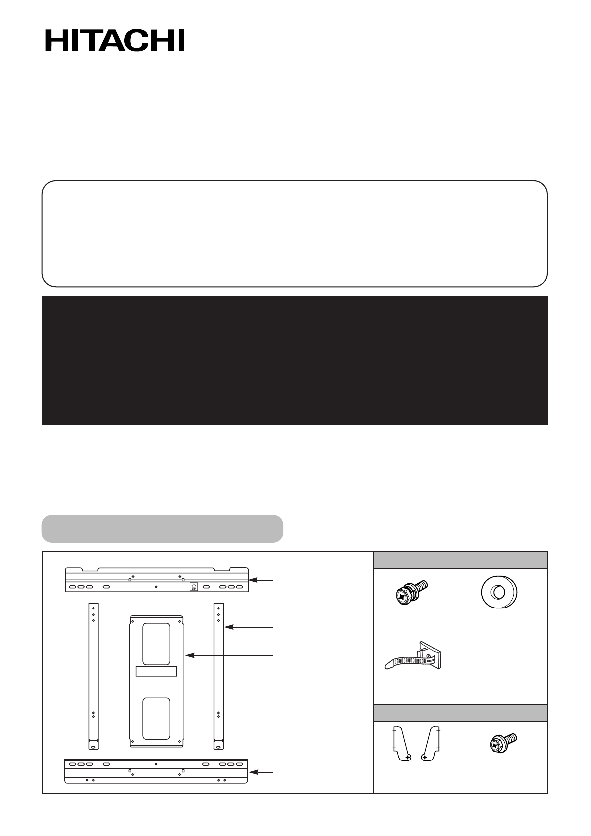
Parts Configuration Chart
In the parts packing
Wall-mount metal
(top) x 1
M6 x 18 screw
x
10
M5 - 6 flat washer
x
8
Wire clamp
x
2
TV-mount metal
x
2
Wall-mount metal
(center) x 1
Wall-mount metal
(bottom) x 1
Bracket (R),(L)
x
1 each
Parts for CL37-PD2100 only
M6 x 18 screw
x
4
32PD5000, 32PD5200, 32PD5300, 37PD5200, 42PD5000, 42PD5200, 42PD5300, CMP4211/2, CMP4213/4
Page 2
– 2 –
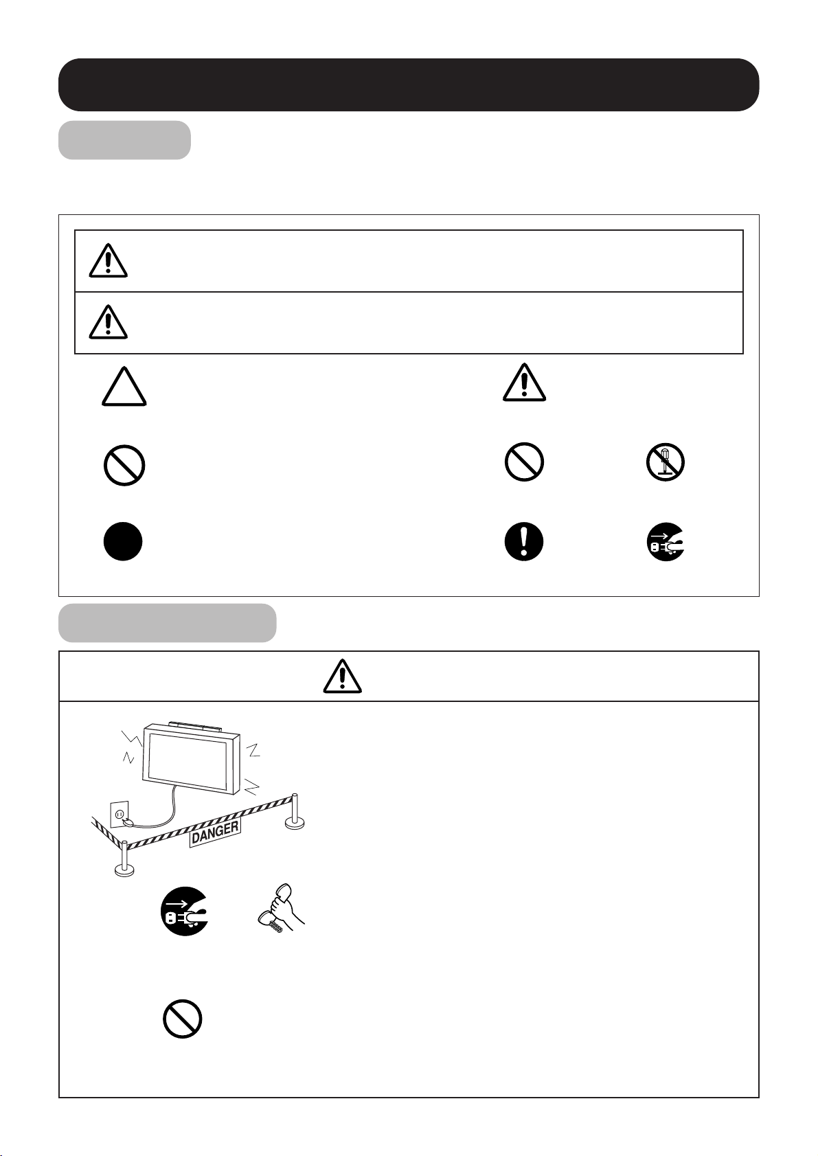
Usage cautions to ensure correct usage
●The following symbols are used to ensure safe usage of the product, to prevent danger to yourself and other
parties and to prevent damage to property.
Symbols
■ This symbol indicates that incorrect handling due to ignoring this symbol
can result in the possibility of personal injury or even death.
■This symbol indicates additional
cautions (including warnings).
WARNING
Caution
(general)
■This symbol indicates forbidden
actions.
■This symbol indicates required actions.
Safety Cautions
Contact your
local dealer.
Disconnect the
power plug from
the power outlet.
■ When a malfunction occurs, disconnect the power
plug from the power outlet and take measures to
prevent other people coming near the plasma TV.
In the cases such as
●
The plasma TV is loose and vibrates to an extreme degree,
●
Mounting screws or parts are loose or missing,
failure to take appropriate actions can result in injury.
Perform the following actions immediately whenever a
malfunction occurs.
①
Turn off the plasma TV power switch.
➁
Disconnect the power plug from the power outlet.
➂
Surround the area with rope, etc., to prevent other people
coming near.
➃
Contact your local dealer.
■ Ask your dealer to install, move or adjust the angle
of the wall-mount unit.
Incorrect installation or adjustment can cause the plasma TV to fall.
Handling by other than
professional contractors
is prohibited.
■ This symbol indicates that incorrect handling due to ignoring this symbol
can result in the possibility of personal injury and physical damage.
CAUTION
Forbidden
(general)
Required
(general)
Disassembly
prohibited
Indicates that the power plug is to be
disconnected from the power outlet.
WARNING
Page 3
– 3 –
■ The wall where the wall-mount unit is to be
installed must be capable of long-term
support of the total load of the plasma TV and
wall-mount unit. Measures should also be
taken to ensure sufficient strength to
withstand the force of earthquakes, vibration
and other external for ces.
Incorrect installation can cause the plasma TV to fall and
cause injury.
Total load of the (plasma TV + wall-mount unit)
= 26kg
•••
CL32-PD2100
34kg
•••
CL37-PD2100
37kg
•••
CL42-PD2100
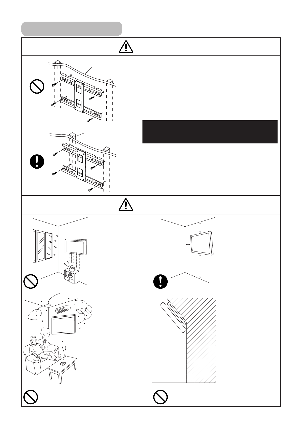
● Installation on a wooden wall
Always install so that the load is supported by a pillar. If the
strength of the pillar is insufficient, add reinforcement. Do
not install on decorative posts or plaster board.
● Installation on a concrete wall
Use commercially available anchors that are capable of
fully supporting the load of the plasma TV.
Plaster board or
thin ply wood, etc.
Pillar or
thick ply wood.
10cm
or more
10cm
or more
10cm
or more
■ Avoid installing in
locations where the
temperature and
humidity are
excessively high,
and where contact
with water is
possible.
These can result in fire
or electrical shock.
Installation Location
WARNING
CAUTION
■ Do not install close
to an airconditioner intake
or outlet.
Do not install in
locations where there
is excessive amounts
of dust, oily smoke or
tobacco smoke.
Fire could result.
■ Do not block the
ventilation holes.
Also provide
sufficient clearance
in regard to the
surroundings to
avoid blocking the
ventilation.
The internal
temperature could
elevate and possibly
result in fire.
■ Install only on a
vertical surface.
Avoid sloped
surface. Also, do
not install facing
upward.
The internal
temperature could
elevate and possibly
result in fire.
Injury or damage could
also result from falling.
Page 4

– 4 –
Installing
CAUTION
■ Do not install in
locations where
there is excessive
vibration or impact.
Injury and damage
could result from
falling.
WARNING
■ Do not install where
there is direct
sunlight and other
strong light.
Strong light could result
in eye fatigue during
usage.
■ Use the specified
bolts and screws in
the specified places
and tighten firmly.
Failure to do this could
cause injury if the
plasma TV falls.
■ Make sure the TVmount metals and
wall-mount metals
are firmly engaged.
Failure to do so could
cause the plasma TV
to fall.
■ Do not alter any of
the parts. And do
not use broken
parts.
This could result in
injury due to the
plasma TV falling.
■ Always use at least
two people to
perform the
installation work.
Injury could result from
dropping heavy
objects.
■ Use care to prevent
the fingers being
caught.
Installation Method
Assembling the wall-mount metals
■
Assemble the wall-mount metal (Top),
(Center) and (Bottom) with 4 M6 x 18
screws.
M6 x 18 screw x 4
Wall-mount metal
(bottom)
Wall-mount metal
(top)
Wall-mount metal
(center)
cutout
Page 5

– 5 –
Mounting the wall-mount unit on the wall
1. Prepare at least four sets of commercially available anchors and screws, etc., for various types of walls.
2. Carefully read the safety cautions concerning installation locations as described in this instruction manual and
then select a suitable location for installation.
3. The relationship between the plasma TV exterior and center, and the positions of the wall-mount unit mounting
holes is shown in the diagram for the various models. Install the anchors in the wall as shown in the diagram and
process the holes as necessary.
● Make sure that the strengths of the wall and the screws are fully sufficient.
32 inch
37 inch
Page 6

4. Fasten the wall-mount unit securely to the wall.
● Clamp to two or more of the long slotted holes in
the upper and lower parts of each wall-mounting
metal in a well-balanced manner.
5. Dressing the cables
● When passing the plasma TV power cord and
signal cables behind the plasma TV, use wire
clamps, etc., to prevent cable damage.
Mount on a firm,
solid surface.
Wall-mount metal (top)
Wall-mount metal (bottom)
Use the washers provided as necessary.
Mounting the TV-mount metals on the plasma TV
Wire clamps
1. Remove the stand.
①
Place a protective sheet cover on the top of a
table and place the plasma TV on the cover with
the back side upward.
➁
Remove the 4 EMI ground screws.
(for CL32-PD2100 only.)
➂
Remove the 4 or 5 (CL37-PD2100) screws
fastening the stand and remove the stand in the
direction indicated by the arrow mark.
2. Installing the TV-mount metals
■Fasten the two TV-mount metals to the back of the
plasma TV with 4 M6 x18 screws.
Remove the 4 EMI ground
screws.(CL32-PD2100)
Plasma TV
Table
Remove the 4 screws
– 6 –
cutout
Protective sheet cover
Remove the screws
(CL37-PD2100)
CL32-PD2100
Stand
4 M6 x 18 screws
The 4th TV-mount
metal hole
The 3rd TV-mount
metal hole
TV-mount metal
42 inch
Page 7

– 7 –
CL42-PD2100
CL37-PD2100
TV-mount metal
①
Fasten the bracket (R) , (L) to the TV mount metal
with 4 M6 x18 screws.
➁
Fasten the two TV-mount metals to the back of the
plasma TV with 4 M6 x18 screws.
4 M6 x 18 screws
Bracket
(R),(L)
4 M6 x 18 screws
The 1st TV-mount
metal hole
Bracket
■Fasten the two TV-mount metals to the back of the
plasma TV with 4 M6 x18 screws.
The 2nd TV-mount
metal hole
The 5th TV-mount
metal hole
Installing the plasma TV on the wall mount
Make sure that
the top cutouts
and catchs are
engaged.
●The plasma TV
should always be
carried by at least
two people.
●Disconnect the
plasma TV power
cord and all
cables.
①
Hang the TV-mount metal catches on the wall-mount unit cutouts.
➁
Fasten with 2 M6 x 18 screws from the bottom.
➂
After make sure all mouting works are completely done, connect power cord and signal cables.
Cutout
Catch
TV-mount metal
2 M6 x 18 screws
Wall-mount unit
Page 8

Product Specifications
External Dimensions
Dimension (A),(B)
Model A B
CL32-PD2100 377 113
CL37-PD2100 414 100
CL42-PD2100 414 51
Mass 2.6kg
Main material Steel sheet
Surface treatment
Angle adjustment
Products mounted
Black electrodeposited baked paint
Vertical fix
Hitachi Plasma TV CL32-PD2100 , CL37-PD2100 , CL42-PD2100
Page 9

Hitachi, Ltd. Tokyo, Japan
International Sales Division
THE HITACHI ATAGO BUILDING,
No. 15 –12 Nishi Shinbashi, 2 – Chome,
Minato – Ku, Tokyo 105-8430, Japan.
Tel: 03 35022111
HITACHI EUROPE LTD,
Whitebrook Park
Lower Cookham Road
Maidenhead
Berkshire
SL6 8YA
UNITED KINGDOM
Tel: 01628 643000
Fax: 01628 643400
Email: consumer-service@hitachi-eu.com
HITACHI EUROPE GmbH
Munich Office
Dornacher Strasse 3
D-85622 Feldkirchen bei München
GERMANY
Tel: +49-89-991 80-0
Fax: +49-89-991 80-224
Hotline: +49-180-551 25 51 (12ct/min)
Email: HSE-DUS.service@hitachi-eu.com
HITACHI EUROPE srl
Via Tommaso Gulli N.39, 20147
Milano, Italia
ITALY
Tel: +39 02 487861
Tel: +39 02 38073415 Servizio Clienti
Fax: +39 02 48786381/2
Email: customerservice.italy@hitachi-eu.com
HITACHI EUROPE S.A.S
Lyon Office
B.P. 45, 69671 BRON CEDEX
FRANCE
Tel: 04 72 14 29 70
Fax: 04 72 14 29 99
Email: france.consommateur@hitachi-eu.com
HITACH EUROPE AB
Egebækgård
Egebækvej 98
DK-2850 Nærum
DENMARK
Tel: +45 43 43 6050
Fax: +45 43 60 51
Email: csgnor@hitachi-eu.com
Hitachi Europe Ltd
Bergensesteenweg 421
1600 Sint-Pieters-Leeuw
BELGIUM
Tel: +32 2 363 99 01
Fax: +32 2 363 99 00
Email: sofie.van.bom@hitachi-eu.com
www.hitachidigitalmedia.com
HITACHI EUROPE S.A.
364 Kifissias Ave. & 1, Delfon Str.
152 33 Chalandri
Athens
GREECE
Tel: 1-6837200
Fax: 1-6835964
Email: service.hellas@hitachi-eu.com
HITACHI EUROPE S.A.
Gran Via Carlos III, 86, planta 5
Edificios Trade - Torre Este
08028 Barcelona
SPAIN
Tel: 93 409 2550
Fax: 93 491 3513
Email: atencion.cliente@hitachi-eu.com
HITACHI Europe AB
Box 77 S-164 94 Kista
SWEDEN
Tel: +46 (0) 8 562 711 00
Fax: +46 (0) 8 562 711 13
Email: csgswe@hitachi-eu.com
HITACHI EUROPE LTD (Norway) AB
STRANDVEIEN 18
1366 Lysaker
NORWAY
Tel: 67 5190 30
Fax: 67 5190 32
Email: csgnor@hitachi-eu.com
HITACHI EUROPE AB
Neopoli / Niemenkatu 73
FIN-15140 Lahti
FINLAND
Tel : +358 3 8858 271
Fax: +358 3 8858 272
Email: csgnor@hitachi-eu.com
HITACHI EUROPE LTD
Na Sychrove 975/8
101 27 Pr aha 10 – Bohdalec
CZECH REPUBLIC
Tel: +420 267 212 383
Fax: +420 267 212 385
Email: csgnor@hitachi-eu.com
 Loading...