


INSTALLATION AND OPERATION MANUAL
MANUAL DE INSTALACIÓN Y FUNCIONAMIENTO
INSTALLATIONS- UND BETRIEBSHANDBUCH
MANUEL D’INSTALLATION ET DE
FUNCTIONNEMENT
MANUALE D’INSTALLAZIONE E D’USO
MANUAL DE INSTALAÇÄO E DE
FUNCIONAMENTO
BRUGER- OG MONTERINGSVEJLEDNING
INSTALLATIE- EN BEDIENINGSHANDLEIDING
HANDBOK FÖR INSTALLATION OCH ANVÄNDING
ЕГЧЕЙСЙДЙПЕГКБФБУФБУЗУКБЙЛЕЙФПХСГЙБУ
PSC-5T
CONTROL TIMER (7-DAY TIMER)
ENGLISHENGLISH
ESPAÑOL
DEUTCH
FRANÇAIS
FRANÇAIS
ITALIANO
PORTUGUESDANSK
DANSK
SVENSKASVENSKA
NEDERLANDSNEDERLANDS
Do not perform installation work, without referring to our installation manual.
No realice la instalación de este equipo, sin antes consultar este manual de instalación.
Bei der Installation unbedingt die Hinweise in der Installationsanleitung beachten.
Consulter notre manuel avant de réaliser une quelconque installation.
Realizzare l’installazione, seguendo quanto indicato in questo manuale.
Nao inicie os trabalhos de montagem, sem consultar o nosso manual de montagem.
Udfor ikke installationsarbejder uden forst at donsultere vores vejledning.
Voer geen enkele handeling uit om de apparatuur alvorens deze hadleiding te hebben
doorgelezen.
Utför inte nagra installationsarbeten utan att först läsa var installationsmanual
Мзн Юуефе уфзн егкбфЬуфбуз, чщсЯт рсйн нб Эчефе ухмвпхлехиеЯ бхфo фп егчейсЯдйп егкбфЬуфбузт


ESPAÑOLDEUTSCHFRANÇAISPORTUGÊSDANSKNEDERLANDSSVENSKA ITALIANOEΛΛHNIKA ESPAÑOL
Õ
DANGER – Immediate hazard which WILL result in severe injury or death.
PELIGRO – Riesgos inmediatos que PRODUCIRÁN lesiones personales graves e incluso
la muerte.
GEFAHR – Unmittelbare Gefahrenquellen, die zu schweren Verletzungen oder zum Tod
führen.
DANGER – Dangers instantanés de blessures corporelles sévères ou de mort.
PERICOLO – Pericolo immediato che PRODURRÀ ferite gravi o la morte.
PERIGO – Problemas imediatos que IRÃO resultar em graves ferimentos pessoais ou
morte.
FARE – Overhængende fare, som VIL resultere i alvorlig personskade eller dødsfald.
GEVAAR – Onmiddellijke risico's die ernstige persoonlijke verwondingen of de dood ten
gevolge kunnen hebben.
FARA – Omedelbar risk som medför svår personskada eller död.
KINAYNO – Άµεσος κίνδυνος που ΘΑ έχει ως αποτέλεσµα σοβαρές σωµατικές βλάβες ή
θάνατο.
Ô
WARNING – Hazards or unsafe practices which COULD result in severe personal injuries
or death.
AVISO – Riesgos o prácticas poco seguras que PODRÍAN producir lesiones personales e
incluso la muerte.
WARNUNG – Gefährliche oder unsichere Anwendung, die zu schweren
Körperverletzungen oder zum Tod führen kann.
ATTENTION – Utilisation dangereuse ou sans garantie de sécurité qui PEUT provoquer de
sévères blessures personnelles ou la mort.
AVVISO – Pericoli o azioni pericolose che POTREBBERO avere come esito lesioni fisiche
gravi o il decesso.
AVISO – Riesgos o prácticas poco seguras que PUEDEN producir lesiones personales e
incluso la muerte
ADVARSEL – Farer eller farlig brug, som KAN resultere i alvorlig personskade eller
dødsfald.
WAARSCHUWING – Gevaren of onveilige praktijken die ernstig persoonlijk letsel of de
dood tot gevolg KUNNEN hebben.
VARNING – Risker eller osäkra tillvägagångssätt som KAN leda till svåra personskador
eller dödsfall.
ΠΡΟΕΙ∆ΟΠΟΙΗΣΗ – Κίνδυνοι ή επικίνδυνες πρακτικές, οι οποίες ΜΠΟΡΕΙ να έχουν ως
αποτέλεσµα σοβαρές σωµατικές βλάβες ή θάνατο.
CAUTION – Hazards or unsafe practices which COULD result in minor personal injury or
product or property damage.
PRECAUCIÓN – Riesgos o prácticas poco seguras que PODRÍAN provocar lesiones
personales de menor importancia o daños en el producto u otros bienes.
VORSICHT – Gefährliche oder unsichere Anwendung, die geringfügigen Personen-,
Produkt- oder Sachschaden verursachen kann.
PRECAUTION – Utilisation dangereuse ou sans garantie de sécurité qui PEUT provoquer
des blessures mineures ou des dommages au produit ou aux biens.
ATTENZIONE – Pericoli o azioni pericolose che POTREBBERO avere come esito lesioni
fisiche minori o danni al prodotto o ad altri beni.
CUIDADO – Perigos e procedimentos perigosos que PODERÃO PROVOCAR danos
pessoais ligeiros ou danos em produtos e bens.
FORSIGTIG – Farer eller farlig brug, som KAN resultere i mindre skade på personer,
produkt eller ejendom.
LET OP – Gevaren of onveilige praktijken die licht persoonlijk letsel of beschadiging van
het product of eigendommen tot gevolg KUNNEN hebben.
VARSAMHET – Risker eller farliga tillvägagångssätt som KAN leda till mindre
personskador eller skador på produkten eller på egendom.
ΠΡΟΣΟΧΗ – Κίνδυνοι ή επικίνδυνες πρακτικές, οι οποίες ΜΠΟΡΕΙ να έχουν ως
αποτέλεσµα την πρόκληση ελαφρών σωµατικών βλαβών ή καταστροφή περιουσίας.


SAFETY SUMMARY
1/1
ENGLISH
1.
SAFETY SUMMARY
Õ
DANGER:
DO NOT pour water into the control timer (hereafter called “Timer”). This product is equipped
with electrical parts. If poured, it will cause a serious electrical shock.
Ô
WARNING:
DO NOT perform installation work and electrical wiring connection by yourself. Contact your
distributor or dealer of HITACHI and ask them for installation work and electrical wiring by
service person.
CAUTION:
- DO NOT install the indoor unit, outdoor unit, Timer and cable at such places as;
- where there is oil vapor and the oil is dispersed
- where the hot springs are near (in a sulfuric environment)
- where generation, flowing, staying or leaking of flammable gas is detected
- where the sea is near (in the salty environment)
- an acid or alkaline environment
- DO NOT install the indoor unit, outdoor unit, Timer and cable within approximately 3 meters
from strong electromagnetic wave radiators such as medical equipment. In case that the Timer
is installed in a place where there is electromagnetic wave radiation, shield the Timer and
cables by covering with the steel box and running the cable through the metal conduit tube.
- In case that there is electric noise at the power source for the indoor unit, provide a noise filter.
2.
INSTALLATION WORK
2.1.
SELECTION OF INSTALLATION PLACE
Select a suitable place for handling and determine the installation place of the Timer with the
customer’s acceptance.
Do not install the Timer at such places as;
- where children can touch
- where the air from the air conditioner is directly discharged
2.2.
BEFORE INSTALLATION
This packing contains the following parts:
GROUP
HITACHI
Control Timer
3 screws M4x16L For fixing the
Holding Bracket onto the wall
Cable (1 m)

2/2
INSTALLATION WORK
2.3.
INSTALLATION SPACE
In case of installing the Timers in vertical line,
keep a distance more than 50mm between the
Timers vertically.
If the distance is insufficient, the front cover of
the Timer can not open wide enough.
2.4.
INSTALLATION PROCEDURES]
1. Insert the edge of the screwdriver into the groove parts at the bottom of the holding bracket, push
and turn the screwdriver and remove the Timer from the holding bracket.
2. Attach the Timer to the holding bracket and connect the cable as follows.
In Case of Exposing Remote Control Cable
Fix the holding bracket onto the wall
with screws (accessory).
Select and cut the knockout hole
according to the direction for drawing
out the cable.
More than 50mm
Screws
(Accessory)
Fix the holding bracket
with the “↑ UP” mark
upward.
Determine the direction for drawing
out the cable according to the cable
arrangement and cut the knockout
hole (one of five positions marked
with in the left figure).
In case of using accessory cable,
draw out the cable from one of the
knockout holes at the lower side.
Groove Part
Holding
Bracket
Groove Part
Screw
Driver
Screw
Driver
A
pprox. 6mm
Groove Part
Figure Seen from Bottom Side

INSTALLATION WORK
2/3
ENGLISH
Lead the cable through the groove.
NOTE:
In case of connecting the accessory cable to the connector, remove the protection case.
Attach the Timer onto the holding bracket.
Band
(Field-Supplied)
Cable
Twist Pair Cable
Accessory Cable
Attach the
stopper to the
cable at the
inside of the
draw-out hole.
Cable
Band (FieldSupplied)
Connector
Terminal
Board
ÙÙÙÙStep 1:
Insert the hooks of the Timer to
the holes at the upper side of the
holding bracket.
ÙÙÙÙStep 2:
Push the lower part of the Timer
toward the holding bracket.
ÙÙÙÙStep 3:
When the click sound is heard, the
Timer is attached to the holding
bracket and the mounting work is
completed.Check to ensure that the
4 hooks at the position
are correctly
inserted.

2/4
INSTALLATION WORK
When Using Switch Box
Prepare a field-supplied JIS Box
(JIS C 8336-1988).
Run the cable through the conduit tube
in the wall.
Attach the holding bracket onto the
switch box.
Connect the cable to the connector on PCB or the terminal.
Attach the Timer onto the holding bracket.
CAUTION:
Pay attention so that the cable may not be slack. If the cable is slack as shown in the right
figure, the cable cord (especially the naked part) may be clamped at the hole and it may cause
a faulty operation.
The following 5 types are available.
1.Switch Box for 1 Controller
(Without Cover)
2.Switch Box for 2 Controllers
(Without Cover)
3.Switch Box for 1 Controller
(With Cove r)
4.Switch Box for 2 Controllers
(With Cove r)
5. Outlet Box (With Cover)
The cable is not
exposed.
Run the cable
through the conduit
tube in the wall and
connect the cable
inside the switch
box.
Screws
(Accessory)
Fix the holding bracket
with the “↑ UP” mark
upward.
Connector
Terminal
Board
ÙÙÙÙStep 1:
Insert the hooks of the Timer to the holes at the upper
side of the holding bracket.
ÙÙÙÙStep 2:
Push the lower part of the Timer toward the holding
bracket.
ÙÙÙÙStep 3:
When a click sound is heard, the Timer is attached to the
holding bracket and the mounting work is completed.

ELECTRICAL WIRING
3/5
ENGLISH
3.
ELECTRICAL WIRING
Use this Timer with Remote Control Switch or Central Station.
CAUTION:
- Use the twist pair cable (1P-0.75mm
2
) as a transmitting wire cable for prevention of the
malfunction. In case of a cable length less than 30 m also can be used:
- Shielded pair cable (Shield connected to earth by one side)
- Normal pair cable
- Keep a distance more than 30cm between the remote control cable and the transmission wire
of indoor units.
Electrical Wiring
1. In case of using Timer with PC-P1HE
2. In case of using Timer with PC-2H2
3. In case of using Timer with PSC-5S (Central Station)
PSC-5T
PC-P1H
Indoor Unit
Transmission Wire
between Outdoor
Unit and indoor Unit
(H-LINK)
Twist Pair cable 1P-0.75mm²
(Max. 100m)
Field-Supplied
PSC-5T
PC-2H2
Indoor Unit
Transmission Wire
between Outdoor
Unit and indoor Unit
(H-LINK)
A
ccessory Cable (1m)
TIMER
REMOCON
(white)
(yellow)
Connector
CN12 or
CN13
PSC-5T PSC-5S
A
ccessor
y
Cable (1m)
Connector
To other central
Stations
Twist Pair Cable
1P-0.75mm²
(Max. 1000m)
A
vailable for H-LINK
connection (to be
connected to the
terminal boards
1 and 2 of Indoor
unit or Outdoor unit
Up to 8 units of central Station (PSC-5S) and Timer
(PSC-5T) can be connected to the H-LINK system
One Timer control one Central Station and plural
central Stations can not be controlled by one Timer
Power Supply:
A
C220V or 240V
CN1
TB2

4/6
SETTING OF DIP SWITCH
4.
SETTING OF DIP SWITCH
Set the two dip switches on the PCB as follows.
(The factory-settings for dip switches of DSW1
and DSW2 are all OFF.)
Dip Switch Setting
DSW Setting
Pin No.
Contents
of Setting
OFF ON
Remarks
1
2
3
For Address
Setting
Refer to the table below.
Setting is required only when the
central station (PSC-5S) is used
together. Set the address of the
central station to be controlled.
DSW1
4
For Other
Controller
Used
Together
Except for
PC-P1HE
PC-P1H
Set #4 pin ON when the remote
control switch (PC-P1H) is used
together.
1
Setting for
prohibition of
remote control
operation after
stopping at
OFF TIME
Setting
is not
available.
Setting is
available.
Remote control operation is not
available after stopping at OFF
TIME. Remote control operation
is available again at ON TIME
while stopping.
(This setting is available only
when the remote control switch
(PC-P1HE) or the central station
(PSC-5S) is used together.)
2
For Other
Controller
Used
Together
PSC-5S
Except for
PSC-5S
Set #2 pin according to the other
controller used together.
3 Not Used
––
Do not change the setting
(#3 pin: OFF).
DSW2
4 Not Used
––
Do not change the setting
(#4 pin: OFF).
Setting of DSW1 (For Address Setting)
Address 0 1 2 3
Setting of
DSW1
ON
1 2 3 4ON1 2 3 4ON1 2 3 4ON1 2 3 4
Address 4 5 6 7
Setting of
DSW1
ON
1 2 3 4ON1 2 3 4ON1 2 3 4ON1 2 3 4
NOTE:
The mark “Ø” indicates position of dips switches.

SWITCH NAMES AND FUNCTIONS
5/7
ENGLISH
5.
SWITCH NAMES AND FUNCTIONS
5.1.
LIQUID CRYSTAL DISPLAY SECTION
The figure below shows all the indications for reference.
The actual display during operation is different.
Model: PSC-5T
Order No:60299957
❶
Indication of Present Time
Indication of Setting Time and Holiday Day
This indicates the Operation Mode, SET or
MONITOR, and the Holiday day if it is
selected.
Indication of Present Day of the week
Indication of Running Day of the week
Whenever the running day is set, this light
is on.
Run Indicator (Red Lamp)
Change Switch of Operation Mode
(SET/MONITOR)
By depressing this switch the control timer
is changed to the setting mode, the “SET”
indication is turned on and the “;” mark is
flickered. Depressing again the "SET" mode
is turned off and the setting mode is changes
to monitor mode.
Change Switch of Setting Pattern (A/B)
There are two (2) patterns (A and B) set for
the weekly schedule. Each pattern can be set
with three (3) times ON/OFF setting for each
weekly day. By depressing this switch the
pattern activated (A or B) is selected.
Setting Switch of Holiday
By depressing this switch when the “SET”
indication is on, the “HOLI” indication is turned
on and the selected day is set as “Holiday”.
Depressing it again, the holiday setting is
canceled.
Setting Switch of Present time
By depressing this switch the “SET” indicator
and “;” mark are flickered and present time
can be set.
Setting Switch of Day of a Week
Day of week is selected by this switch when
“SET” display is flickering or indicated.
Depressing this switch, the “;” mark move in
order of “Sun > Mon > ... > Sat”. Depressing
the DAY after "Sat", all the “;” mark are
selected. Depressing it again “;” mark returns
to “Sun”.
¡
Setting Switch of Running Day (RUN DAY)
By depressing the “RUN DAY” switch, the
selected day is set as the running day and the
“•” mark is turned on. Depressing again it is
turned off and the selected day is cancelled
¢
Change Switch of SELECT Setting
By depressing the “∆ SELECT ∇” switch the 1,
2 or 3 of ON TIME and OFF TIME is selected.
£
Change Switch of ON/OFF TIMER Setting
When “SET” display is flickering, by depressing
the “ON/OFF TIMER” the timer is changing to
the ON/OFF time setting mode and the “hour”
indication of ON TIME is flickering.
¤
CANCEL Switch of Setting Time
Depressing this switch when timer is set, the
indication of ON TIME or OF TIME is changed
to “-.—”.
¥
OK Switch
By depressing this switch the selection on
setting process is accepted.
¦
Setting Switch of HOUR-MINUTE
By depressing “∆” or “∇” the hour or minute is
set when “SET” display is flickering or indicated.
§
Indication of ON TIME and OFF TIME Setting
It is indicating the setting conditions of the
selected day
¨
Indication of Weekly Scheduled Pattern
(A or B)
NOTE:
The present time and the ON/OFF setting
time are indicated by 12 hours units
(AM 0:00-12:00, PM 0:00-12:00)
Indication
Operation
switch
When opening the
cover, pull the cover
toward the arrow
direction

6/8
OPERATION PROCEDURE
6.
OPERATION PROCEDURE
SETTING PRESENT DAY AND PRESENT TIME
(<Example> present Day: Friday, Present Time: 5:15 PM).
During the setting mode, the setting of the present time is not available
when depressing the “PRESENT” switch more than 3 seconds.
Ô
ATTENTION:
1. Supply power to the unit.
Ô
ATTENTION:
- Supply power the unit more than 12 hours before unit
operation for compressor protection.
- Do not cut off power during the term of using air conditioner.
The right figure shows the case of the present time at AM
0:00 on Sunday. (When the power is turned ON, the present
time is not set.)
2. Depress the “PRESENT” switch for more than 3 seconds.
The display is changed to the present time setting mode, and the
“SET” indicator and the “W” mark are flickered.
The right figure shows the case that ON time and OFF time are
not set.
3. Set the “W” mark at the present day by depressing
the “DAY” switch.
Depress the “OK” switch after setting the present day, the “W”
mark is turned on and “hour” indication is flickered.
The right figure shows the case of setting the day at “Friday”.
4. Set “hour” indication at the present hour by depressing
the “HOUR/MINUTE < or =” switch.
Depress the “OK” switch after setting the present hour, “hour”
indication is turned on and “minute” indication is flickered.
The right figure shows the case of setting the hour at “PM 5”.
5. Set “minute” indication at the present minute by depressing
the “HOUR/MINUTE < or =” switch.
Depress the “OK” switch after setting the present minute, the
present day and the present time are fixed, and the present time
setting mode is changed to the monitor mode. “minute” indication
is turned on and the “SET” indication is turned off.
The right figure shows the case of setting the minute at “15”.

OPERATION PROCEDURE
6/9
ENGLISH
CHANGING WEEKLY SCHEDULE PATTERN (A OR B)
There are 2 (two) patterns (A or B) set for the weekly schedule.
Each pattern can be set with 3 (three) times ON/OFF settings for
each weekly day.
<Function>
To select the pattern for setting and operating the schedule.
The schedule of A or B pattern can be set for each week and
changed for a season.
1. Depress the “SET/MONITOR” switch.
The control timer is changed to the setting mode and the “SET”
indication is turned on.
2. Depress the “A/B” switch.
The set pattern is changed (“A” to “B”) by depressing the “A/B”
switch.
The right figure shows the case of selecting the set pattern “B”.
3. Depress the “SET/MONITOR” switch.
The “SET” mode is turned off and the setting mode is changed to
the monitor mode.
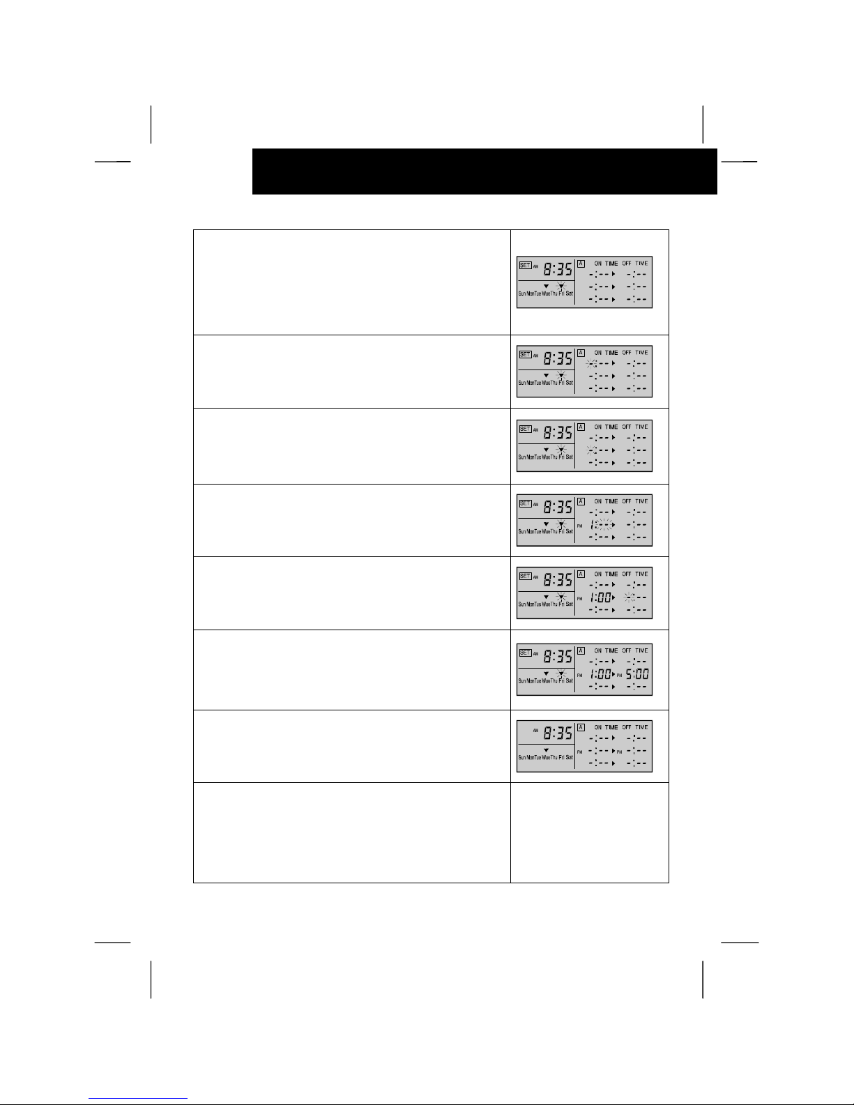
SETTING ON/OFF TIME
<Example> “A” pattern, Friday, Setting 2, PM 1:00 (ON) /
PM 5:00 (OFF)
In case that the remote control switch (PC-P1H(E)) is used
together, both setting of ON TIME and OFF TIME are required
for setting a, 2 and 3. (The setting of ON TIME (or OFF TIME)
only is not available).
In case that the central station (PSC-5S) is used together, the
setting of ON TIME (or OFF TIME) only is available.
Ô
ATTENTION:
1. Depress the “SET/MONITOR” switch.
The control timer is changed to the setting mode, the “SET”
indication is turned on and the “
W
” mark is flickered.
The right figure shows the case of changing to the setting
mode.
2. Select “A” or “B” pattern by depressing the “A/B” switch.
Refer to “B”. Changing weekly Schedule pattern A or B
for changing the pattern
6/10
OPERATION PROCEDURE
3. Select the weekly day to set ON/OFF control by
depressing the “DAY” switch.
By depressing the “DAY” switch, the flickering “
W
” mark moves
in order of “Sun → Mon → ... → Sat”. Depressing the “DAY”
switch after “Sat”, all the “
W
” marks (from “Sun” to “Sat”) are
flickered. In this case, the setting is the same for all days of a
week. Depressing the “DAY” switch once again, the flickering
“
W
” mark returns to the position of “Sun”.
4. Depress the “ON/OFF TIME” switch.
The Timer is changed to the ON/OFF time setting mode
and the “hour” indication of ON TIME is flickered.
The right figure shows the case of changing to the ON/OFF
time setting mode.
5. Select the setting 1,2 or 3 by depressing
the “
∆∆∆∆
SELECT
∇∇∇∇”
switch.
By depressing the “∆ SELECT ∇” switch, the “hour” indication
moves flickering.
The right figure shows the case of selecting the setting 2.
6. Set the “hour” indication of ON TIME by depressing
the “HOUR/MINUTE < or =” switch.
After setting the “hour” indication, depress the “OK” switch and
the “minute” indication of ON TIME to be set is flickered.
The right figure shows the case of setting the hour “PM 1.—”.
7. Set the “minute” indication of ON TIME by depressing
the “HOUR/MINUTE < or =” switch.
After setting the “minute” indication, depress the “OK” switch
and the “hour” indication of OFF TIME to be set is flickered.
The right figure shows the case of setting the hour “PM 1:00”.
8. Set the time of “OFF TIME” by the same procedure of
setting the time of “ON TIME”.
After setting the time of “OFF TIME”, the flickering indication of
“OFF TIME” is turned on and the ON/OFF time setting mode is
changed to the setting mode.
The right figure shows the case of setting the hour “PM 5:00”.
9. Depress the “SET/MONITOR” switch.
The “SET” indication is turned off and the control timer is
changed to the monitor mode.
The right figure shows the case of indicating the setting
condition of the present day.
Depressing the “CANCEL” switch when setting ON time
(procedure 6) or OFF time (procedure 8), the indication of ON
TIME or OFF TIME is changed to “-:--”. Depressing the “OK”
switch in this condition, the setting is canceled.
In case of using the Timer together with other controller than
the remote control switch.
PC-P1HE and the central station PSC-5S, the setting of ON time
and OFF time is required.
Ô
ATTENTION:

OPERATION PROCEDURE
6/11
ENGLISH
SETTING RUNNING DAY
<Function>
To set the day for actual operation of the running schedule
set before. (Though the ON time and OFF time are set, the
schedule operation is not available unless the running day
is set.)
<Example> “B” pattern, Tuesday
1. Depress the “SET/MONITOR” switch.
The timer is changed to the setting mode, the “SET” indication
is turned on and the “
W
” mark are flickered.
2. Select “A” or “B” pattern by depressing the “A/B” switch.
The right figure shows the case of selecting the set pattern “B”.
3. Select the running day by depressing the “DAY” switch.
Refer to 3. of “Setting ON/OFF Time” for the indication of the
“
W
” mark.
The right figure shows the case of selecting the day “Tuesday”.
4. Depress the “RUN DAY” switch, the selected day is set
as the running day and the “
::::
” mark is turned on at the
selected day.
By depressing the “RUN DAY” switch again, the running day
setting is canceled and the “
::::
” mark is turned off.
The right figure shows the case of selecting the day “Tuesday”.
5. Depress the “SET/MONITOR”.
The “SET” indication is turned off and the control timer is
changed to the monitor mode.
SETTING HOLIDAY
<Function> To cancel the running schedule temporarily.
The schedule operation is canceled only once at the day set
as “holiday”. After that, the schedule operation is available
again. This function is used in case that there are any
irregular holidays.
<Example> “B” pattern, Tuesday
1. Depress the “SET/MONITOR” switch.
The timer is changed to the setting mode, the “SET” indication
is turned on and the “
W
” mark are flickered.
2. Select “A” or “B” pattern by depressing the “A/B” switch.
The right figure shows the case of selecting the set pattern “B”.

6/12
OPERATION PROCEDURE
3. Select the day to be set as “holiday” by depressing the
“DAY” switch.
Refer to 3. “Setting ON/OFF Time” for the indication of
the “
W
” mark.
The right figure shows the case of selecting the day “Tuesday”.
4. Depress the “HOLIDAY” switch, the “HOLI” indication is
turned on and the selected day is set as “holiday”.
In the case that the selected day is not set as running day the
“
:
” mark is turned off. The holiday setting is not available for
the day. (In case that all days of a week are selected, only
the running day is set as “holiday”).
By depressing the “HOLIDAY” switch again, the holiday
setting is canceled.
5. Depress the “SET/MONITOR”.
The “SET” indication is turned off and the control timer is
changed to the monitor mode.
In case of setting the present day as “holiday”, the “holiday”
setting is available from that time and the schedule operation
is canceled until the next day. In that case, the same day after
a week is not “holiday”.
Ô
ATTENTION:
CHECKING CONTENTS OF SETTING
1. Depress the "DAY" switch at the monitor mode (when the
“SET” indication is turned off), the “
W
” mark moves and the
setting contents of the day with the “
W
” mark is indicated.
The right figure shows the case of selecting the day “Tuesday”.
CAUTION:
- The control timer has a built-in back-up
battery and the clock function is available
within 2 weeks in case of power failure.
If the power failure continues more than
2 weeks, set the present time again.
- The RUN indicator is turned on at ON
time and turned off at OFF time.
In case that that the indoor unit operation
is started or stopped by the remote
control switch or the central station used
together with the timer, the RUN
indicator is not changed.
- The flickering of the RUN indicator
shows the abnormal condition of
the Timer. Check to ensure that the
wiring connection and the setting of dip
switches are correct. In the case that
the RUN indicator is still flickered after
checking, contact your distributor or
dealer of HITACHI.
CAUTION:
- It may take approximately 15 seconds
to start (or stop) operation after ON time
(or OFF time) according to the controller
used together.
- The operation can not be started or
stopped during the setting mode condition.
After the completion of setting, set
the Timer at the monitor mode. (After
3 minutes with leaving the Timer at the
setting mode, the Timer is changed to
the monitor mode automatically.)
- In the case that the Timer is used with the
central station (PSC-5S), the setting by
the central station is required. Refer to the
“Installation & Operation Manual of Central
Station” for details.
 Loading...