

Page 1

ENGLISH
DEUTSCH
FRANÇAIS
ITALIANO
ESPAÑOL
NEDERLANDS
NORSK
TECHNICAL
PORTGÊS
Liquid Crystal Projector
PJLC2001
USER'S MANUAL
Please read this user's manual thoroughly to ensure correct usage through understanding.
BEDIENUNGSANLEITUNG
Bitte lessen Sie diese Bedienungsanleitung zugunsten der korrekten Bedienung
aufmerksam.
MANUEL D'UTILISATION
Nous vous recommandons de lire attentivement ce manuel pour bien assimiler le
fonctionnement de l'appareil.
MANUALE D'ISTRUZIONI
Vi preghiamo voler leggere attentamente il manuale d'sitruzioni in modo tale da poter
comprendere quanto riportato ai fini di un corretto utilizzo del proiettore.
MANUAL DE USUARIO
Lea cuidadosamente este manual del usuario para poder utilizar corretamente el
producto.
GEBRUIKSAANWIJZNG
Lees voor het qebruik alstublieft deze handleiding aandachtig door, om volledig profijt te
hebben van de uitgebreide mogelijkheden.
BRUKERHÅNDBOK
Vennligst les denne bruksanvisningen grundig for å være garantert driftssikker bruk.
INSTRUÇÕES DO PROPRIETÁRIO
Para assegurar o uso correto do equipamento, por favor leia atentamente este manual do
usuário.
TECHNICAL
Page 2

ENGLISH
Liquid Crystal Projector
USER'S MANUAL
ENGLISH-1
Thank you for purchasing this HITACHI liquid crystal projector.
Please read the accompanying manual “SAFETY INSTRUCTIONS” and this “USER'S
MANUAL” thoroughly to ensure correct usage through understanding. After reading,
store this instruction manual in a safe place for future reference.
CONTENTS
FEATURES....................................P.2
BEFORE USE................................P.2
Contents of Package...........................P.2
Part Names .........................................P.3
Loading the Battery.............................P.4
INSTALLATION.............................P.5
Installation of the projector and Screen
.....P.5
Angle Adjustment................................P.5
Cabling................................................P.6
Power Connection...............................P.6
Example of System Setup...................P.7
Plug & Play..........................................P.7
OPERATIONS................................P.8
Switching the Power Supply ON/OFF
....P.8
Basic Operation...................................P.9
Setup Menu.......................................P.11
Input Menu ........................................P.12
Image Menu ......................................P.13
Options Menu....................................P.14
No Signal Menu.................................P.15
MAINTENANCE...........................P.16
Lamp .................................................P.16
Air Filter Maintenance .......................P.18
Other Maintenance............................P.18
TROUBLESHOOTING.................P.19
OSD Message...................................P.19
Indicators Message...........................P.20
Symptom...........................................P.21
SPECIFICATIONS .......................P.22
WARRANTY AND AFTER-SERVICE
...P.23
REGULATORY NOTICES ...........P.24
Tables:
Table 1. Installation Reference .............P.5
Table 2. Basic Operations.....................P.9
Table 3. Setup Menu...........................P.11
Table 4. Input Menu ............................P.12
Table 5. Image Menu ..........................P.13
Table 6. Options Menu........................P.14
Table 7. No Signal Menu.....................P.15
Table 8. OSD Message.......................P.19
Table 9. Indicator Message.................P.20
Table 10. Symptom.............................P.21
Table 11. Specifications......................P.22
NOTE:
* The information in this manual is subject to change without notice.
* The manufacturer assumes no responsibility for any errors that may appear in this manual
* The reproduction, transmission or use of this document or contents is not permitted without
express written authority.
TRADEMARK ACKNOWLEDGMENT:
* PS/2, VGA and XGA are registered trademarks of International Business Machines Corporation.
* Apple, Macintosh, Mac and ADB are registered trademarks of Apple Computer, Inc.
* VESA and SVGA are trademarks of the Video Electronics Standard Association.
* Windows is a registered trademark of Microsoft Corporation.
* Carefully observe the trademarks and registered trademarks of all companies, even when not
mentioned.
Page 3

ENGLISH-2
FEATURES
This liquid crystal projector is used to project various computer signals as well as NTSC / PAL /
SECAM video signals onto a screen. Little space is required for installation and large images can
easily be realized.
• Outstanding brightness
The UHB lamp and high-efficiency optical system assure a high level of brightness.
• Partial magnification function
Interesting parts of images can be magnified for closer viewing.
• Distortion correction function
Distortion-free images are quickly available.
BEFORE USE
Contents of package
Make sure all of the following items are included in the package. If anything is missing, please
contact your dealer.
NOTE: Keep the original packing material for future reshipment.
Projector
User’s Manual
Quick Guide
Power Cord
UK Type
Power Cord
Europe Type
RGB Cable
Video Cable Audio Cable
(Stereo Mini)
Scart Socket
VIDEO
STANDBY/ON
POSITION
FREEZE
MAGNIFY
VOLUME
AUTO
OFF
TIMER BLANK
MENU
SELECT
RGB
MUTE
MENU RESET
Remote Controller
containing Battery
Carrying Bag
S-Video Cable
Safety Instructions
Page 4

ENGLISH-3
BBEEFFOORREE UUSSEE ((ccoonnttiinnuueedd))
ENGLISH
Part Names
Power Switch
AC Inlet
(to the Power Cord)
Ventilation Openings
(Intake)
Zoom Knob
Focus Ring
Remote Control Sensor
Lens
Slide Lens Door
Foot Adjuster
FRONT/LEFT VIEW OF
THE PROJECTOR
RESET Button
MUTE Button
INPUT Button
STANDBY/ON Button
Foot Adjuster Button
Air Filter and Intake
(for the Cooling Fan)
Speaker
Rear Foot Adjuster
LAMP Indicator
TEMP Indicator
POWER Indicator
MENU Button
Ventilation Openings
(exhaust)
REAR/RIGHT VIEW OF
THE PROJECTOR
Terminal Panel
(Refer below)
S-VIDEO Terminal
RGB IN Terminal
CONTROL Terminal
VIDEO Terminal
Remote Control Sensor
AUDIO IN Terminal
TERMINAL PANEL
Control Panel (Refer to P.8 "OPERATIONS")
Page 5

ENGLISH-4
BBEEFFOORREE UUSSEE ((ccoonnttiinnuueedd))
Part Names (continued)
VIDEO
STANDBY/ON
POSITION
FREEZE
MAGNIFY
VOLUME
AUTO
OFF
TIMER BLANK
MENU
SELECT
RGB
MUTE
MENU RESET
STANDBY/ON Button
Button
Button
Button
Button
MENU Button
MAGNIFY Button
MAGNIFY Button
MAGNIFY Button
AUTO Button
TIMER Button
Battery Holder
OFF
VIDEO Button
RGB Button
MENU SELECT Button
POSITION Button
RESET Button
VOLUME Button
VOLUME Button
FREEZE Button
MUTE Button
BLANK Button
REMOTE CONTROLLER
Loading the Battery
First Loading:
In original packing, the battery is installed in the battery
holder of the remote controller with protection film(the
transparent filmsome of which is inside the battery
folder). Pull out the protection film to load the battery.
Replacing:
1. See the reverse side of the remote controller.
2. Pinch the groove and pull out battery holder as the
drawing right.
3. Remove the worn battery.
4. Install the new battery with “+” side facing.
5. Push in and click the battery holder.
Pull out
“+” side
Battery Holder
(Refer to P.8 "OPERATIONS")
CAUTION
Danger of explosion if battery is incorrectly replaced.
Be careful in handling the battery according to instructions of the accompanying manual
“SAFETY INSTRUCTIONS” and this manual.
Replace only with the same or equivalent type recommended by the manufacturer.
Use the 3V micro lithium battery type no. CR2025 only.
When you dispose the battery, you must obey the law in the relative area or country.
Keep the battery away from children and pets.
Page 6

ENGLISH-5
INSTALLATION
Installation of the Projector and Screen
Install the projector in a suitable environment according to instructions of the
accompanying manual “SAFETY INSTRUCTIONS” and this manual.
Refer to the drawing and table below for determining of the screen size and projection distance.
TOP VIEW
SIDE VIEW
a: Distance from the LCD projector to the screen.
The projection distances shown in the table below
are for full size (800 x 600 dots).
b: Distance from the lens center to the bottom of the
screen (a, b: +/-10%)
Table 1. Installation Reference
Screen size
(inches)
a (inches)
b (inches)
Min. Max.
40 37 46 3
60 57 69 5
80 77 93 7
100 96 116 9
120 116 139 10
150 145 174 13
200 194 233 17
a
b
Angle Adjustment
Use the foot adjuster on the bottom of the projector to adjust the projection angle. It is variable
within 0˚ to 10˚ approximately.
1. Lift up the front side of the projector, and pressing
the foot adjuster button, adjust the projection angle.
2. Release the button to lock at the angle to be fixed.
3. Turn the rear foot adjuster to adjust the left-right slope.
Do not release the foot adjuster button unless the projector is being held; otherwise, the
projector could overturn or the fingers could get caught and cause personal injury.
Foot Adjuster
ENGLISH
Press the foot adjuster button
Rear Foot Adjuster
Installation of liquid crystal projector
Please basically use liquid crystal projector at the horizontal position.
If you use liquid crystal projector by the lens up position, the lens down position and the side
up position, this may cause the heat inside to build up and become the cause of damage.
Be especially careful not to install it with ventilation holes blocked.
Page 7

Power Connection
Use the correct one of the enclosed power cords depending on the power outlet to be used.
Connect the AC inlet of the projector to the power outlet firmly by the power cord.
ENGLISH-6
IINNSSTTAALLLLAATTIIOONN ((ccoonnttiinnuueedd))
RGB Signal Input:
Connect the RGB IN terminal of the projector to the display signal output of the computer by the
enclosed RGB cable. Secure the screws on the connector and tighten.
For some modes, the enclosed Mac adapter is necessary. Refer to P.22 “SPECIFICATION” and
“Table 1. Example of Compatible Computer Signal” of the TECNICAL section.
NOTE: Some computers may have multiple display screen modes. Use of some of these modes will
not be possible with this projector.
Video Signal Input:
Connect the VIDEO terminal of the projector to the video signal output of the video tape recorder
by the enclosed video cable except for S-Video signal.
For S-Video signal, use the S-VIDEO terminal of the projector and the optional cable for S-Video.
Audio Signal Input:
Connect the AUDIO IN terminal of the projector to the audio signal output by the enclosed audio
cable.
RS-232C:
Connect the CONTROL terminal of the projector to the computer by the optional RS-232C cable.
Refer to the manual of the RS-232C cable for the control command.
Cabling
* Incorrect connecting could result in fire or electrical shock. Please read this manual and
the separate “SAFETY INSTRUCTIONS”.
* Before connecting, turn off to all devices to be connected.
WARINING
Be carful in handling the power cord according to
instructions of the accompanying manual "SAFETY
INSTRUCTIONS" and this manual.
Connect the power cord firmly. Avoid using a loose,
unsound outlet or contact failure.
AC Inlet
Power Cord
Power outlet
*Before connecting, read the
instruction manuals of the devices to
be connected, and make sure that the
projector is compatible with the
device.
*The cables (Power cord, RGB cable
and other cables) may have to be used
with the core set to the projector side.
Use the cables which are included
with the projector or specified.
Core
Page 8

ENGLISH-7
IINNSSTTAALLLLAATTIIOONN ((ccoonnttiinnuueedd))
ENGLISH
Example of system setup
AC Inlet
Video tape recorder with S jack
Video tape recorder
Computer
(desktop type)
Computer
(notebook type)
Plug & Play
This projector is VESA DDC 1/2B compatible. Plug & play is possible by connecting to a computer
that is VESA DDC (Display Data Channel) compatible.
(Plug & play is a system configured with peripheral equipment including a computer and display,
and an operating system.
NOTE: Use the RGB cable included with this projector when using plug & play. With other cables,
pins (12) (14) (15) are sometimes not connected.
RGB Cable
RS-232C Cable
Connecting with notebook computer
When connecting with notebook computer, set to valid the RGB external image output
(setting CRT display or simultaneous display of LCD and CRT).
Please read instruction manual of the notebook for more information.
Page 9

ENGLISH-8
OPERATIONS
Switching the Power Supply ON/OFF
Switching Power ON
1. Check that the power cord is connected correctly.
2. Set the power switch to [ | ]. The standby mode is selected, and the Power indicator is turned to
orange.
3. Press the STANDBY/ON button on the control panel or the remote. Warm-up begins and the
Power indicator blinks in green.
4. The Power indicator ceases blinking and turns to green when power is ON. Open the lens door.
5. Adjust picture size using the projection lens Zoom Knob.
6. Adjust focus using the projection lens Focus Ring.
Switching Power OFF
1. Press the STANDBY/ON button on the control panel or the remote for approximately two
second. The projector lamp is extinguished and lamp cooling begins. The Power indicator blinks
orange during lamp cooling. Pressing the STANDBY/ON button has no effect while the
Power indicator is blinking.
2. The system assumes the Standby mode when cooling is complete, and the Power indicator ceases
blinking and changes to orange. Check that the indicator is orange and set the Power switch to
[
O
].
3. The Power indicator is extinguished when power is OFF. Do not forget to close the lens door.
Power Switch
Slide Lens door
STANDBY/ON Button
POWER Indicator
VIDEO
STANDBY/ON
POSITION
FREEZE
MAGNIFY
VOLUME
MENU
SELECT
RGB
MENU RESET
STANDBY/
ON Button
ZOOM knob
FOCUS ring
Please read this manual, and the separate “SAFETY INSTRUCTIONS” thoroughly before
using the equipment. Always ensure that the equipment is used safely.
Except in emergencies, do not switch power OFF unless the Power indicator is orange as
it will reduce the life of the projector lamp.
Page 10

ENGLISH-9
OOPPEERRAATTIIOONNSS ((ccoonnttiinnuueedd))
ENGLISH
Basic Operation
The Basic operations shown in Table 2 is performed from the projector control panel or the supplied
remote. (items indicated by * may be used from the control panel)
Table 2 . Basic Operation
(It continue the next page.)
Use the remote controller at a distance of approximately 3m from the sensor on the front
of the projector, and within a range of 30° left-right. Strong light and obstacles will
interfere with operation of the remote.
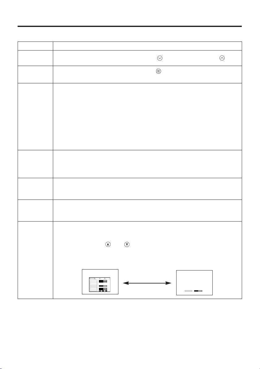
Item Description
INPUT
SELECT
Changes in input signal in sequence: Press INPUT button.*
RGB → VIDEO → S-VIDEO (→ RGB)
Select RGB input: Press RGB button.
VIDEO/S-VIDEO → RGB
Select VIDEO/S-VIDEO input: Press VIDEO button.
RGB → VIDEO/S-VIDEO S-VIDEO ↔ VIDEO
* The selected signal name is displayed for approximately three seconds
when the input signal is changed.
POSITION
Set/Clear position adjustment mode: Press POSITION button.
The [ ] icon is displayed in the POSITION mode.
Image position adjustment: Press the , , and buttons in the
position adjustment mode.
* Valid only in the MAGNIFY mode with VIDEO/S-VIDEO input.
* The [ ] icon is extinguished, and the position adjustment mode cleared
automatically, after approximately ten seconds of inactivity.
RESET *
Initialise menu items: Select an item and press the RESET button.
Initialise position adjustment: Press the RESET button
and the POSITION mode.Valid only when RGB signal is input.
* Valid except for VOLUME, LANGUAGE and H PHASE.
MAGNIFY
Set MAGNIFY mode: Press the MAGNIFY button.
Move magnified area: Run Position Adjustment in MAGNIFY mode.
Adjust magnification: Press MAGNIFY / in MAGNIFY mode.
Clear MAGNIFY mode: Press MAGNIFY button.
* MAGNIFY is cleared by running or setting AUTO, ASPECT, INPUT
SELECT or VIDEO, or by changing the input signal.
OFF
FREEZE
Set/Clear FREEZE mode: Press FREEZE button.
The [
II
] icon is displayed, and the image frozen, in the FREEZE mode.
* FREEZE is cleared by running or setting POSITION, VOLUME, MUTE,
Auto Adjust, BLANK ON/OFF, or MENU ON/OFF, or by changing the
input signal.
* Do not forget to clear frozen static images.
Page 11
ENGLISH-10
OOPPEERRAATTIIOONNSS ((ccoonnttiinnuueedd))
Table 2. Basic Operation (continued)
Item Description
VOLUME
Volume adjustment : Reduce VOLUME ↔ Increase VOLUME
MUTE *
Set/Clear Mute mode: Press the MUTE button.
No sound is heard in the MUTE mode.
AUTO
Automatic adjustment at RGB input: Press the AUTO button.
Horizontal position(H.POSIT), vertical position (V.POSIT),clock phase
(H.PHASE), and horizontal size(H.SIZE) are automatically adjusted. Use
with the window at maximum size in the application display.
Automatic adjustment at VIDEO/S-VIDEO input:
Press the AUTO button.
A signal type appropriate for the input signal is selected automatically.
Valid only when AUTO is set for VIDEO on the menu.
* This operation requires approximately ten seconds. It may not function
correctly with some input signals.
TIMER
ON/OFF
Timer start/stop: Press the TIMER button.
Count-down and display by the minute from the initial value (1~99) set in
TIMER on the Options menu to 0.
* The timer is not displayed in the BLANK MODE or FREEZE MODE.
BLANK
ON/OFF
Set/Clear Blank mode: Press the BLANK button.
No image is displayed in the Blank mode. The screen color is as set in
BLANK on the Image menu.
MENU
ON/OFF
*
Menu display start/stop: Press the MENU button.
* The menu display is terminated automatically after approximately ten
seconds of inactivity.
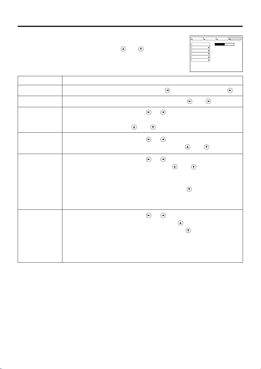
MENU
SELECT
Select menu type: Press the MENU SELECT button.
Allows the user to select the normal menu or the single menu. Only the
selected item is displayed on the single menu, and other items are
displayed with the and buttons as with the normal menu.
* Valid only when the Setup menu is used. Push the MENU SELECT button
after selecting items such as "BRIGHTNESS".
Normal menu Single menu
CONTRAST
-2
BRIGHT
CONTRAST
V POSIT
H POSIT
H PHASE
H SIZE
COLOR BAL R
COLOR BAL B
ASPECT
0
-2
+1
0
0
100
100
800
SETUP INPUT OPT.IMAGE
(MENU SELECT)
Page 12

ENGLISH-11
OOPPEERRAATTIIOONNSS ((ccoonnttiinnuueedd))
ENGLISH
Setup Menu
The following adjustments and settings are
possible when SETUP is selected at the top of
the menu. Part of the Setup menu differs
between RGB input and VIDEO/S-VIDEO
input. Select an item with the and
buttons, and start operation. Use the Single
menu to reduce menu size (see Table 2, MENU
SELECT).
Table 3. Setup Menu
VIDEO/S-VIDEO
RGB
BRIGHT
CONTRAST
V POSIT
H POSIT
H PHASE
H SIZE
COLOR BAL R
COLOR BAL B
ASPECT
0
-2
+1
0
0
100
100
800
SETUP INPUT OPT.IMAGE
BRIGHT
CONTRAST
SHARPNESS
COLOR
TINT
COLOR BAL R
COLOR BAL B
ASPECT
0
+1
+1
0
0
0
0
SETUP INPUT OPT.IMAGE
Item Description
RGB
VIDEO
S-VIDEO
BRIGHT
Adjustment: Dark ↔ Light
✔ ✔
CONTRAST
Adjustment: Weak ↔ Strong
✔ ✔
V POSIT
Adjustment: Down ↔ Up
✔
-
H POSIT
Adjustment: Left ↔ Right
✔
-
H PHASE
Adjustment: Left ↔ Right
* Adjust to eliminate flicker.
✔
-
H SIZE
Adjustment: Small ↔ Large
* The image may not be displayed correctly if the horizontal
size is excessive. In such cases, press the RESET
button, and initialise the horizontal size.
✔
-
SHARPNESS
Adjustment: Soft ↔ Clear
-
✔
COLOR
Adjustment: Light ↔ Dark
-
✔
TINT
Adjustment: Red ↔ Green
* Valid only when NTSC or NTSC 4.43 signal is received.
-
✔
COLOR BAL R
Adjustment: Light ↔ Dark
✔ ✔
COLOR BAL B
Adjustment: Light ↔ Dark
✔ ✔
ASPECT
Select image aspect ratio:
4:3[ ]
↔ 16:9[ ] ↔ 4:3 small[ ]
Select position of image:
Press button while 16:9[ ]/4:3 small[ ] is selected.
Center
→ Down → Up ( → Center )
* 4:3 small may not be displayed correctly with some input
signals.
✔ ✔
Page 13

ENGLISH-12
OOPPEERRAATTIIOONNSS ((ccoonnttiinnuueedd))
Input Menu
The following functions are available when INPUT is selected on the
menu. Select an item with the and buttons, and start or stop
operation with the and buttons.
Table 4. Input Menu
fH:38kHz
fV:60Hz
RGB
VIDEO
AUTO
SETUP INPUT OPT.IMAGE
Item Description
RGB
Displays RGB input frequency: Displays the horizontal and vertical sync
signal frequency for RGB input.
* Valid only at RGB input.
VIDEO
Select video signal type:
Select the signal type with the and buttons.
Select NTSC, PAL SECAM, NTSC4.43, M-PAL, or N-PAL as appropriate
for the input signal.
Auto Adjust is valid at VIDEO/S-VIDEO input when AUTO is selected,
and is then used for automatic selection of the signal type.
* Use this function when the image becomes unstable (eg. the image
becomes irregular, or lacks color).
* Auto Adjust requires approximately ten seconds. It may not function
correctly with some input signals. Pressing the AUTO button in this case
may correct this problem.
AUTO
Automatic adjustment at RGB input: Select EXECUTE with the button.
Horizontal position, vertical position, clock phase, and horizontal size are
automatically adjusted when
EXECUTE
is selected. Use with the window
at maximum size in the application display.
Automatic adjustment at VIDEO/S-VIDEO input:
Select
EXECUTE
with the button.
A signal type appropriate for the input signal is selected automatically
when
EXECUTE
is selected. Valid only if AUTO is selected in VIDEO (see
above).
* This operation requires approximately ten seconds. It may not function
correctly with some input signals. Pressing the AUTO button in this case
may correct this problem.
* This function is the same as for Auto Adjust in Basic operation.
Page 14

ENGLISH-13
OOPPEERRAATTIIOONNSS ((ccoonnttiinnuueedd))
ENGLISH
Image Menu
The following adjustments and settings are available when IMAGE is
selected on the menu. Select an item with the and buttons, and
start operation.
Table 5. Image Menu
KEYSTONE
BLANK
MIRROR
START UP
+1
SETUP INPUT OPT.IMAGE
Item Description
KEYSTONE
Adjustment:
Reduce size of bottom of image
↔ Reduce size of top of image
BLANK
Select blank screen color: Select color with the and buttons.
* The image is cleared when the BLANK mode is set with BLANK ON, or
when there is no signal, and the entire screen is displayed in the selected
color. Note that if TURN OFF is selected on the START UP the blank
screen is displayed in blue when there is no signal.
MIRROR
Operation start/stop: Press the or button.
Select Mirror status: Select mirror status with and buttons.
START UP
Operation start/stop: Press the or button.
Setup initial screen display: Select TURN ON with the button.
Clear initial screen display: Select TURN OFF with the button.
* Note that if TURN OFF is selected the blank screen is displayed in blue
when there is no signal.
Page 15
ENGLISH-14
OOPPEERRAATTIIOONNSS ((ccoonnttiinnuueedd))
Options Menu
The following adjustments and settings are available when OPT. is
selected on the menu. Select an item with the and buttons, and
start operation.
Table 6. Options Menu
VOLUME
MENU COLOR
TIMER
LANGUAGE
AUTO OFF
SYNC ON G
128
SETUP INPUT OPT.IMAGE
Item Description
VOLUME
Volume adjustment: Reduce VOLUME ↔ Increase VOLUME
MENU COLOR
Select menu background color: Select with the and buttons.
TIMER
Operation start/stop: Press the or button.
Setup initial timer value:
Set 1~99 minutes with the and buttons.
LANGUAGE
Operation start/stop: Press the or button.
Select menu display language: Select with the and buttons.
AUTO OFF
Operation start/stop: Press the or button.
Set AUTO OFF: Set 1~99 minutes with the and buttons.
The system automatically enters the standby mode when a signal is
not received for the set time.
Clear AUTO OFF: Select STOP (0 min.) with the button.
When stop is selected the system does not enter the standby mode
even if no signal is received.
SYNC ON G
Operation start/stop: Press the or button.
SYNC ON G valid: Select TURN ON with the button.
SYNC ON G invalid: Select TURN OFF with the button.
* May not be displayed correctly with some input signals when SYNC
ON G is valid. In such cases, remove the signal connector so that no
signal is received, set SYNC ON G to invalid, and reconnect the
signal.
Page 16
ENGLISH-15
OOPPEERRAATTIIOONNSS ((ccoonnttiinnuueedd))
ENGLISH
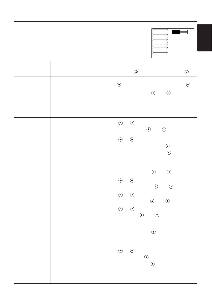
No Signal Menu
The same adjustments and settings are available as with the Image and
Options menus when the MENU button is pressed during display of the
“NO INPUT IS DETECTED ON ***” or “SYNC IS OUT OF RANGE
ON ***” message while no signal is received.
Table 7. No Signal Menu
VOLUME
KEYSTONE
BLANK
MIRROR
START UP
MENU COLOR
TIMER
LANGUAGE
AUTO OFF
SYNC ON G
40
+1
Item Description
VOLUME
Volume adjustment: Reduce VOLUME ↔ Increase VOLUME
KEYSTONE
Adjustment:
Reduce size of bottom of image
↔ Reduce size of top of image
BLANK
Select blank screen color: Select color with the and buttons.
* When the blank mode is set with BLANK ON, by absence of a signal, or by
input of a non-standard signal, the image is cleared and the complete screen is
displayed in the selected colour. Note that if No Display is selected in Initial
Screen the blank screen is displayed in blue when no signal is received.
MIRROR
Operation start/stop: Press the or button.
Select Mirror status: Select mirror status with and buttons.
START UP
Operation start/stop: Press the or button.
Setup initial screen display: Select TURN ON with the button.
Clear initial screen display: Select TURN OFF with the button.
* Note that if TURN OFF is selected the blank screen is displayed in
blue when there is no signal.
MENU COLOR
Select menu background color: Select with the and buttons.
TIMER
Operation start/stop: Press the or button.
Setup initial timer value: Set 1~99 minutes with the
and
buttons.
LANGUAGE
Operation start/stop: Press the or button.
Select menu display language: Select with the and buttons.
AUTO OFF
Operation start/stop: Press the or button.
Set AUTO OFF: Set 1~99 minutes with the and buttons.
The system automatically enters the standby mode when a signal is
not received for the set time.
Clear AUTO OFF: Select STOP (0 min.) with the button.
When STOP is selected the system does not enter the standby mode
even if no signal is received.
SYNC ON G
Operation start/stop: Press the or button.
SYNC ON G valid: Select TURN ON with the button.
SYNC ON G invalid: Select TURN OFF with the button.
* May not be displayed correctly with some input signals when SYNC ON G is
valid. In such cases, remove the signal connector so that no signal is received,
set SYNC ON G to invalid, and reconnect the signal.
Page 17
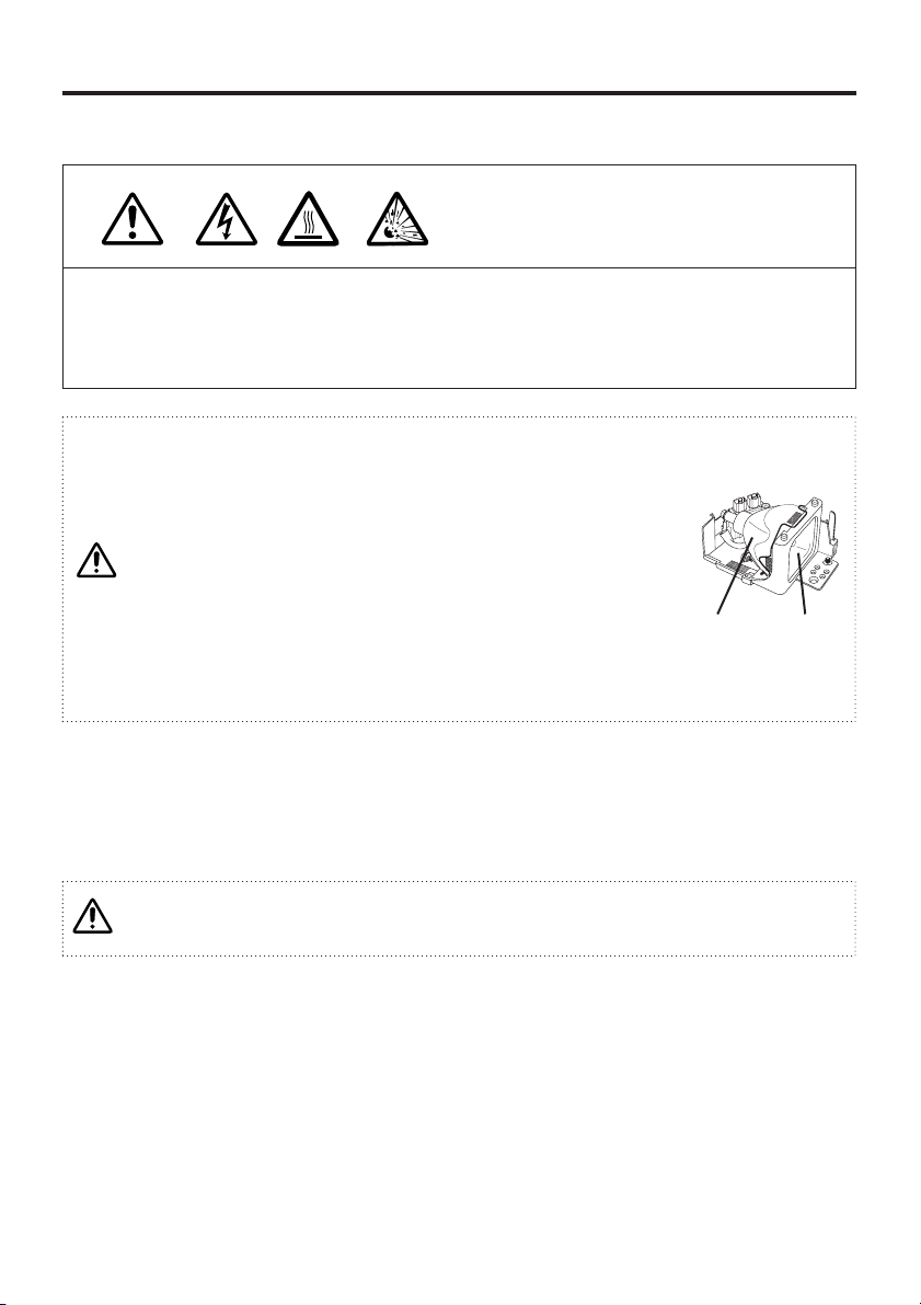
* For disposal of used lamp, treat according to the instruction of community authorities.
* Since the lamp is made of glass, do not apply shock to it and do
not scratch it.
* Also, do not use old lamp. This could also cause explosion of the
lamp.
* If it is probable that the lamp has exploded (explosive sound is
heard), disconnect the power plug from the power outlet and ask
your dealer to replace lamp.
The lamp is covered by front glass , but, in rare cases, the
reflector and the inside of the projector may be damaged by
scattered broken pieces of glass, and broken pieces could cause
injury when being handled.
* Do not use the projector with the lamp cover removed.
ENGLISH-16
MAINTENANCE
Lamp
HIGH VOLTAGE
HIGH TEMPERATURE
HIGH PRESSURE
Contact your dealer before replacing the lamp.
(Option lamp: DT00301 for CP-S220W / DT00301 or DT00381 for CP-S220WA)
Before replacing the lamp, switch power OFF, remove the power cord from the power outlet, and
wait approximately 45 minutes until the lamp has cooled. The lamp may explode if handled at high
temperatures.
Lamp Life
Projector lamps have a finite life. The image will become darker, and hues will become weaker,
after a lamp has been used for a long period of time.
Replace the lamp if the LAMP indicator is red, or the CHANGE THE LAMP message (see P.19
Table 8) appears when the projector is switched ON.
Lamp
Front
glasss
Reflector
The LAMP indicator is also red when the lamp unit reaches high temperature. Before
replacing the lamp, switch power OFF, wait approximately 20 minutes, and switch power
ON again. If the LAMP indicator is still red, replace the lamp.
Page 18
ENGLISH-17
MMAAIINNTTEENNAANNCCEE ((ccoonnttiinnuueedd))
ENGLISH
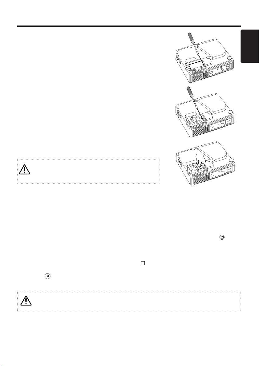
Replacing the Lamp
1. Switch the projector OFF, remove the power cord from the
power outlet, and wait at least 45 minutes for the unit to cool.
2. Prepare a new lamp.
3. Check that the projector has cooled sufficiently, and gently
turn it upside down.
4. Loosen the two screws as shown in the diagram, and remove
the lamp cover.
5. Loosen the one screw, and gently remove the lamp while
holding the grips. Touching the inside of the lamp case may
result in uneven coloring.
6. Install the new lamp and tighten the one screw firmly. Also
steadily push the opposite side of the screwed lamp into the
unit.
7. Replace the lamp cover in position and tighten the two
screws firmly.
8. Gently turn the projector right-side up.
* Ensure that screws are tightened properly. Screws not
tightened fully may result in injury or accidents.
* Do not use the projector with the lamp cover
Resetting the Lamp Timer
Reset the lamp timer after replacing the lamp. When the lamp has been replaced after the LAMP
indicator is red, or the CHANGE THE LAMP message is displayed, complete the following
operation within ten minutes of switching power ON. The power will be turned off automatically in
over 10 minutes.
1. Switch power ON, and press the TIMER button on the remote controller, or the RESET button
on the control panel, for approximately three seconds. The ‘LAMP xxxx hr’ message will appear
on the lamp timer on the bottom of the screen.
2. Press the MENU button on the remote controller, or the RESET button on the control panel,
while the lamp timer is displayed. The ‘LAMP xxxx
→ 0 ■ CANCEL’ message will then
appear.
3. Press the and select 0, and wait until the timer display is cleared.
Do not reset the lamp timer without replacing the lamp. Reset the lamp timer always when
replacing the lamp. The message functions will not operate properly if the lamp timer is
not reset correctly.
Page 19

ENGLISH-18
MMAAIINNTTEENNAANNCCEE ((ccoonnttiinnuueedd))
Air Filter Maintenance
The air filter should be cleaned as described below at intervals of approximately 100 hours.
1. Switch the projector power supply OFF, and remove the power cord from the power outlet.
2. Clean the air filter with a vacuum cleaner.
Other Maintenance
Maintenance Inside the Equipment
For safety reasons, ensure that the equipment is cleaned and checked by the dealer once every two
years. Maintaining the equipment by yourself is dangerous.
Cleaning the Lens
Gently wipe the lens with lens cleaning paper. Do not touch the lens with your hands.
Cleaning the Cabinet and Remote Controller
Gently wipe with a soft cloth. If dirt and stain etc. are not easily removed, use a soft cloth dampened
with water, or water and a neutral detergent, and wipe dry with a soft, dry cloth.
Switch power OFF and remove the power cord from the power outlet before beginning
maintenance work. Please read the separate “SAFETY INSTRUCTIONS” thoroughly to
ensure that maintenance is performed correctly.
* Replace the air filter if contamination cannot be removed, or if it is damaged. Contact
your dealer in such case.(Option Air filter : MU01291)
* Do not use the equipment with the air filter removed.
* When the air filter is clogged with dust etc. the CHECK AIR FLOW message appears on
the screen and the power supply is switched OFF automatically to prevent the
temperature rising inside the projector.
Switch power OFF and remove the power cord from the power outlet before beginning
maintenance work. Please read the separate “SAFETY INSTRUCTIONS” thoroughly to
ensure that maintenance is performed correctly.
* Do not use detergents or chemicals other than those noted above (e.g. benzene or
thinners).
* Do not use cleaning sprays.
* Do not rub with hard materials, or tap the equipment.
Page 20
ENGLISH-19
ENGLISH
TROUBLESHOOTING
OSD Message
The messages as described below may appear on the screen at power ON. Take the appropriate
measures when such a message appears.
Table 8. OSD Messages
Message Contents
CHANGE THE LAMP
AFTER REPLACING LAMP,
RESET THE LAMP TIME.
*1)
The message shown at left appears after the lamp has
been used for more than 1700 hours.
The lamp is approaching the end of its life.
Power is switched OFF automatically when the lamp
reaches the end of its life. Prepare a new lamp for
installation.
Always reset the lamp timer after replacing the lamp.
CHANGE THE LAMP
AFTER REPLACING LAMP,
RESET THE LAMP TIME.
THE POWER WILL TURN OFF
AFTER ** hr.
*1)
The lamp will reach the end of its life in ** hours.
Power will be switched OFF automatically in ** hours.
Replace the lamp as shown in P.16 “Lamp”.
Always reset the lamp timer after replacing the lamp.
CHANGE THE LAMP
AFTER REPLACING LAMP,
RESET THE LAMP TIME.
THE POWER WILL
TURN OFF
AFTER 0 hr.
The lamp has reached the end of its life. Power will be
switched OFF in a few minutes.
Switch power OFF immediately and replace the lamp as
shown in P.16 “Lamp”.
Always reset the lamp timer after replacing the lamp.
NO INPUT IS DETECTED
ON ***
No input signal found.
Check signal input connections and signal sources.
SYNC IS OUT OF RANGE
ON ***
The horizontal or vertical frequency of the input signal is
not within the specified range.
Check the specifications of the equipment and the signal
source.
CHECK THE AIR FLOW
The internal temperature has risen.
Switch power OFF, and wait 20 minutes until the
equipment cools.
Check the following and Switch power ON again.
* Are the ventilation openings blocked ?
* Is the air filter dirty ?
* Is the ambient temperature in excess of 35°C ?
*1) This message is cleared automatically after approximately three minutes, and appears
every time power is switched ON.
Page 21
ENGLISH-20
TTRROOUUBBLLEESSHHOOOOTTIINNGG ((ccoonnttiinnuueedd))
Indicators Message
The POWER indicator, LAMP indicator, and TEMP indicator are lit and blank as follows. Take the
appropriate measures.
Table 9. Indicators Message
POWER
indicator
LAMP
indicator
TEMP
indicator
Contents
Lights
orange
Turns off Turns off The Standby mode has been set.
Blinks
green
Turns off Turns off Warming up. Please wait.
Lights
green
Turns off Turns off ON. Normal operation possible.
Blinks
orange
Turns off Turns off Cooling. Please wait.
Lights
red
Lights
red
Turns off
Lamp is not lit.
The interior of the equipment may be too hot. Switch
power OFF, wait 20 minutes until the equipment cools,
and Switch power ON again. Replace the lamp if the
same problem occurs.
Lights
red
Blinks
red
Turns off
No lamp or lamp cover is found, or hasn’t been fitted in
correctly.
Switch power OFF, and wait for 45 minutes until the
equipment cools. Check fitting of the lamp and lamp
cover, and switch power ON again. Contact your dealer if
the same problem occurs again.
Lights
red
Turns off
Blinks
red
The cooling fan is not operating.
Switch power OFF, and wait for 20 minutes until the
equipment cools. Check for foreign matters in the fan,
and switch power ON again. Contact your dealer if the
same problem occurs again.
Lights
red
Turns off
Lights
red
The interior of the equipment is too hot. *1)
Switch power OFF, and wait for 20 minutes until the
equipment cools. Check whether the ventilation openings
are blocked, whether the air filter is dirty, or whether the
ambient temperature exceeds 35 °C. Then switch power
ON again. Contact your dealer if the same problem
occurs again.
*1) When the internal temperature becomes excessive power is switched OFF
automatically for safety reasons, and the indicator is extinguished. Set the power switch to
[
O
] and wait for 20 minutes until the equipment has cooled sufficiently.
Page 22

ENGLISH-21
TTRROOUUBBLLEESSHHOOOOTTIINNGG ((ccoonnttiinnuueedd))
ENGLISH
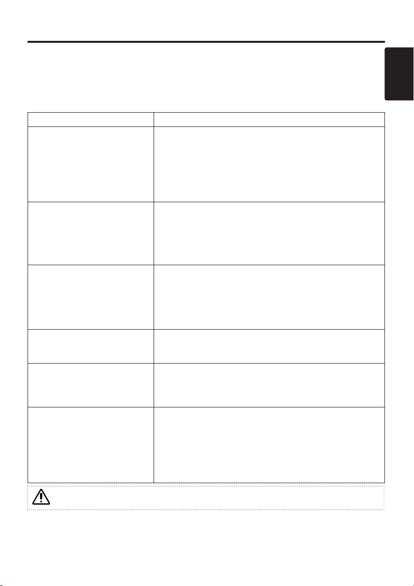
Symptom
Before requesting repair, check in accordance with the following chart. If the situation cannot be
corrected, then contact your dealer.
Table 10. Symptom
This product is supplied with a written warranty. Please read it thoroughly, enter the
required details, and storage in a safe place.
Symptom Possible cause Remedy Page
The power is not
turned on.
The main power switch is not
turned on.
Turn on the main power switch.
6,8
The power cord is
disconnected.
Plug the power cord into an AC
power outlet.
No video or audio.
The input is not correctly set.
Use the projector or remote control
to set.
9
No signal input. Connect correctly.
6,7
Video is present but
no audio.
The projector is not correctly
connected.
Connect correctly.
6,7
The volume is set to minimum.
Press VOLUME on the remote
control or display the menu screen
and adjust the volume.
10,14
Mute is turned on.
Press the MUTE button.
10
Audio is present but
no video.
The projector is not correctly
connected.
Connect correctly.
6,7
The brightness adjustment knob
is rotated fully clockwise.
Select BRIGHT with the MENU
button and the press the button.
11
The slide lens door is still
closed.
Open the slide lens door.
8
Colors are pale and
color matching is
poor.
Color density and color
matching are not correctly
adjusted.
Adjust the video.
11
Images are dark.
Brightness and contrast are not
correctly adjusted.
Adjust the video.
11
The lamp is nearing the end of
its service life.
Replace with a new lamp.
16
Video is blurred.
Focus or H PHASE is out of
adjustment.
Adjust the focus or H PHASE.
11
Page 23

ENGLISH-22
SPECIFICATIONS
NOTE : This specifications are subject to change without notice.
Table 11. Specifications
Item Specification
Product name Liquid crystal projector
Liquid
crystal
panel
Panel size 1.8 cm (0.7 type)
Drive system TFT active matrix
Pixels 480,000 pixels (800 horizontal x 600 vertical)
Lens Zoom lens F=2.0 ~ 2.3 f=18 ~ 21 mm
Lamp 130 W UHB
Speaker 1.0 W
Power supply AC100 ~ 120V, 2.0A / AC220 ~ 240V, 0.9A
Power consumption 200 W
Temperature range 0 ~ 35°C (Operating)
Size 289 (W) x 76 (H) x 210 (D) mm
Weight (mass) 2.4 kg or less
INPUT
signal
RGB
Video: Analog 0.7Vp-p, 75Ω terminator (positive)
H/V. sync.: TTL level (positive/negative)
Compound sync.: TTL level
D-sub 15-pin shrink jack
51
10
6
15
11
7 Ground Green
8 Ground Blue
9 -
1 Video input Red 10 Ground
2 Video input Green 11 -
3 Video input Blue 12 DDC jack
4 - 13
H. sync./ Compound sync.
5 Ground (DDC) 14 Vertical sync
6 Ground Red 15 DDC jack
VIDEO 1.0Vp-p, 75Ω terminator, RCA jack
S-VIDEO
Mini DIN 4-pin jack 1
Brightness signal: 1.0Vpp, 75Ω terminator
2
1
Ground
Ground
2
Color signal: 0.286Vp-p
(burst signal), 75Ω
terminator
AUDIO
200mVrms, 47 kΩ or less (max. 3.0Vp-p)
Stereo mini jack (Speaker output is L/R mixed.)
CONTROL signal D-sub 15-pin shrink jack
Page 24

ENGLISH-23
ENGLISH
SSPPEECCIIFFIICCAATTIIOONNSS ((ccoonnttiinnuueedd))
Dimension Diagram
289
76
45.6
74.5
210
60
WARRANTY AND AFTER-SERVICE
* If a problem occurs with the equipment, first refer to the P.19 “TROUBLESHOOTING” section
and run through the suggested checks. If this does not resolve the problem contact your dealer or
service company. If repairs are possible, and desirable, they will be charged.
Unit : mm
This product is supplied with a written warranty. Please read it thoroughly, enter the
required details, and storage in a safe place.
Page 25

ENGLISH-24
REGULATORY NOTICES
WARNING: This equipment has been tested and found to comply with the
limits for a Class B digital device, pursuant to Part 15 of the FCC Rules. These
limits are designed to provide reasonable protection against harmful
interference in a residential installation. This equipment generates, uses, and
can radiate radio frequency energy and, if not installed and used in accordance
with the instructions, may cause harmful interference to radio communications.
However, there is no guarantee that interference will not occur in a particular
installation. If this equipment does cause harmful interference to radio or
television reception, which can be determined by turning the equipment off and
on, the user is encouraged to try to correct the interference by one or more of
the following measures:
- Reorient or relocate the receiving antenna.
- Increase the separation between the equipment and receiver.
- Connect the equipment into an outlet on a circuit different from that to which
the receiver is connected.
- Consult the dealer or an experienced radio/TV technician for help.
INSTRUCTIONS TO USERS: This equipment complies with the requirements
of FCC (Federal Communication Commission) equipments provided that
following conditions are met.
The cables (Power cord, RGB cable and other cables) may have to be used
with the core set to the projector side. Use the cables which are included with
the projector or specified.
CAUTION: Changes or modifications not expressly approved by the party
responsible for compliance could void the user’s authority to operate the
equipment.
FCC Statement Warning
For the Customers in CANADA
NOTICE: This Class B digital apparatus complies with Canadian ICES-003.
Core
Page 26

TECHNICAL - 1
TECHNICAL
TECHNICAL
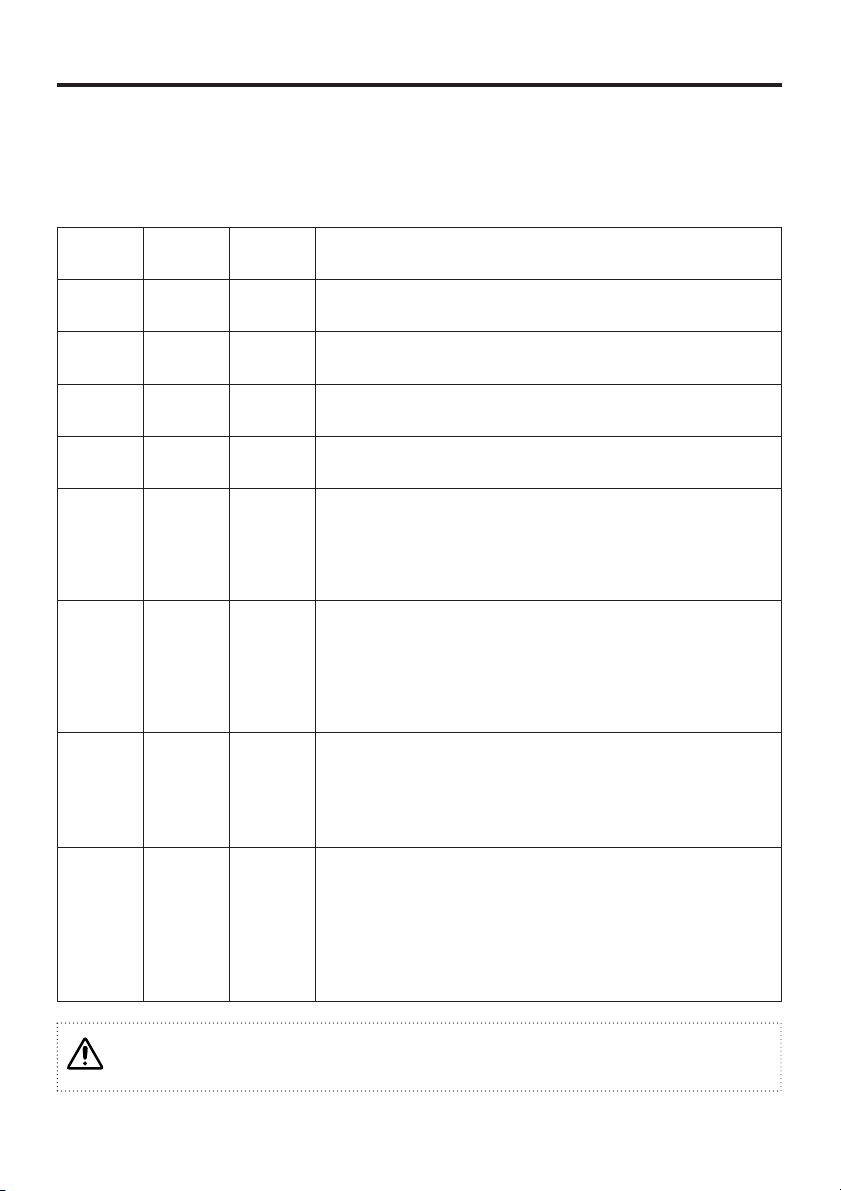
Table 1. Example of computer signal
Resolution
H × V
fH (kHz) fV (Hz) Rating Signal mode
Display
mode
Note 1
720 × 400
37.9 85.0 VESA TEXT Zoom in
640 × 480
31.5 59.9 VESA VGA (60Hz) Zoom in
640 × 480
35.0 66.7 Mac13"mode Zoom in
SW 1 ON
SW 2 ON
640 × 480
37.9 72.8 VESA VGA (72Hz) Zoom in
640 × 480
37.5 75.0 VESA VGA (75Hz) Zoom in
640 × 480
43.3 85.0 VESA VGA (85Hz) Zoom in
800 × 600
35.2 56.3 VESA SVGA (56Hz)
800 × 600
37.9 60.3 VESA SVGA (60Hz)
800 × 600
48.1 72.2 VESA SVGA (72Hz)
800 × 600
46.9 75.0 VESA SVGA (75Hz)
800 × 600
53.7 85.1 VESA SVGA (85Hz)
832 × 624
49.7 74.5 Mac16"mode Zoom out
SW 2 ON
SW 4 ON
1024 × 768
48.4 60.0 VESA XGA (60Hz) Zoom out
1024 × 768
56.5 70.1 VESA XGA (70Hz) Zoom out
1024 × 768
60.0 75.0 VESA XGA (75Hz) Zoom out
Note 1: Mac adapter is necessary to the resolution mode.
Projector is compatible with 13 inch mode and 16 inch mode.
Mac 13" mode=switch 1 and switch 2 are ON.
Mac 16" mode=switch 2 and switch 4 are ON.
ON
OFF
123456
Caution
• Some computers may have multiple display screen modes. Use of some of these modes
will not be possible with this projector.
• Be sure to check jack type, signal level, timing and resolution before connecting this
projector to a computer.
• Depending on the input signal, full-size display may not be possible in some cases. Refer
to the number of display pixels above.
(Example 16 inch mode)
Page 27
TECHNICAL - 2
TTEECCHHNNIICCAALL
((ccoonnttiinnuueedd))
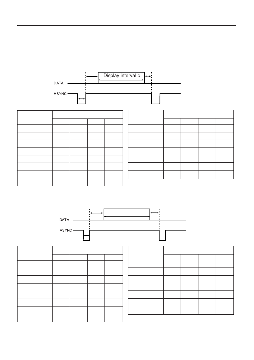
Table 2. Initial set signals
The following signals are used for the initial settings.
The signal timing of some computer models may be different. In such case, refer to adjust the
V.POSIT and H.POSIT of the menu.
DATA
HSYNC
DATA
VSYNC
Display interval c
Back porch b
Sync a
Front porch d
Display interval c
Back porch b
Sync a
Front porch d
Computer /
Signal
Horizontal signal timing (µs)
a b c d
TEXT 2.0 3.0 20.3 1.0
VGA (60Hz) 3.8 1.9 25.4 0.6
Mac 13"mode 2.1 3.2 21.2 2.1
VGA (72Hz) 1.3 3.8 20.3 1.0
VGA (75Hz) 2.0 3.8 20.3 0.5
VGA (85Hz) 1.6 2.2 17.8 1.6
SVGA (56Hz) 2.0 3.6 22.2 0.7
SVGA (60Hz) 3.2 2.2 20.0 1.0
Computer /
Signal
Horizontal signal timing (µs)
a b c d
SVGA (72Hz) 2.4 1.3 16.0 1.1
SVGA (75Hz) 1.6 3.2 16.2 0.3
SVGA (85Hz) 1.1 2.7 14.2 0.6
Mac 16"mode 1.1 3.9 14.5 0.6
XGA (60Hz) 2.1 2.5 15.8 0.4
XGA (70Hz) 1.8 1.9 13.7 0.3
XGA (75Hz) 1.2 2.2 13.0 0.2
Computer /
Signal
Vertical signal timimg (lines)
a b c d
TEXT 3 42 480 1
VGA (60Hz) 2 33 480 10
Mac 13"mode 3 39 480 3
VGA (72Hz) 3 28 480 9
VGA (75Hz) 3 16 480 1
VGA (85Hz) 3 25 480 1
SVGA (56Hz) 2 22 600 1
SVGA (60Hz) 4 23 600 1
Computer /
Signal
Vertical signal timimg (lines)
a b c d
SVGA (72Hz) 6 23 600 37
SVGA (75Hz) 3 21 600 1
SVGA (85Hz) 3 27 600 1
Mac 16"mode 3 39 624 1
XGA (60Hz) 6 29 768 3
XGA (70Hz) 6 29 768 3
XGA (75Hz) 3 28 768 1
Page 28

TECHNICAL - 1
TECHNICAL
TECHNICAL
Table 1. Example of computer signal
Resolution
H × V
fH (kHz) fV (Hz) Rating Signal mode
Display
mode
Note 1
720 × 400
37.9 85.0 VESA TEXT Zoom in
640 × 480
31.5 59.9 VESA VGA (60Hz) Zoom in
640 × 480
35.0 66.7 Mac13"mode Zoom in
SW 1 ON
SW 2 ON
640 × 480
37.9 72.8 VESA VGA (72Hz) Zoom in
640 × 480
37.5 75.0 VESA VGA (75Hz) Zoom in
640 × 480
43.3 85.0 VESA VGA (85Hz) Zoom in
800 × 600
35.2 56.3 VESA SVGA (56Hz)
800 × 600
37.9 60.3 VESA SVGA (60Hz)
800 × 600
48.1 72.2 VESA SVGA (72Hz)
800 × 600
46.9 75.0 VESA SVGA (75Hz)
800 × 600
53.7 85.1 VESA SVGA (85Hz)
832 × 624
49.7 74.5 Mac16"mode Zoom out
SW 2 ON
SW 4 ON
1024 × 768
48.4 60.0 VESA XGA (60Hz) Zoom out
1024 × 768
56.5 70.1 VESA XGA (70Hz) Zoom out
1024 × 768
60.0 75.0 VESA XGA (75Hz) Zoom out
Note 1: Mac adapter is necessary to the resolution mode.
Projector is compatible with 13 inch mode and 16 inch mode.
Mac 13" mode=switch 1 and switch 2 are ON.
Mac 16" mode=switch 2 and switch 4 are ON.
ON
OFF
123456
Caution
• Some computers may have multiple display screen modes. Use of some of these modes
will not be possible with this projector.
• Be sure to check jack type, signal level, timing and resolution before connecting this
projector to a computer.
• Depending on the input signal, full-size display may not be possible in some cases. Refer
to the number of display pixels above.
(Example 16 inch mode)
Page 29

TECHNICAL - 2
TTEECCHHNNIICCAALL
((ccoonnttiinnuueedd))
Table 2. Initial set signals
The following signals are used for the initial settings.
The signal timing of some computer models may be different. In such case, refer to adjust the
V.POSIT and H.POSIT of the menu.
DATA
HSYNC
DATA
VSYNC
Display interval c
Back porch b
Sync a
Front porch d
Display interval c
Back porch b
Sync a
Front porch d
Computer /
Signal
Horizontal signal timing (µs)
a b c d
TEXT 2.0 3.0 20.3 1.0
VGA (60Hz) 3.8 1.9 25.4 0.6
Mac 13"mode 2.1 3.2 21.2 2.1
VGA (72Hz) 1.3 3.8 20.3 1.0
VGA (75Hz) 2.0 3.8 20.3 0.5
VGA (85Hz) 1.6 2.2 17.8 1.6
SVGA (56Hz) 2.0 3.6 22.2 0.7
SVGA (60Hz) 3.2 2.2 20.0 1.0
Computer /
Signal
Horizontal signal timing (µs)
a b c d
SVGA (72Hz) 2.4 1.3 16.0 1.1
SVGA (75Hz) 1.6 3.2 16.2 0.3
SVGA (85Hz) 1.1 2.7 14.2 0.6
Mac 16"mode 1.1 3.9 14.5 0.6
XGA (60Hz) 2.1 2.5 15.8 0.4
XGA (70Hz) 1.8 1.9 13.7 0.3
XGA (75Hz) 1.2 2.2 13.0 0.2
Computer /
Signal
Vertical signal timimg (lines)
a b c d
TEXT 3 42 480 1
VGA (60Hz) 2 33 480 10
Mac 13"mode 3 39 480 3
VGA (72Hz) 3 28 480 9
VGA (75Hz) 3 16 480 1
VGA (85Hz) 3 25 480 1
SVGA (56Hz) 2 22 600 1
SVGA (60Hz) 4 23 600 1
Computer /
Signal
Vertical signal timimg (lines)
a b c d
SVGA (72Hz) 6 23 600 37
SVGA (75Hz) 3 21 600 1
SVGA (85Hz) 3 27 600 1
Mac 16"mode 3 39 624 1
XGA (60Hz) 6 29 768 3
XGA (70Hz) 6 29 768 3
XGA (75Hz) 3 28 768 1
Page 30

Hitachi, Ltd. Tokyo, Japan
International Sales Division
THE HITACHI ATAGO BUILDING,
No. 15 –12 Nishi Shinbashi, 2 – Chome,
Minato – Ku, Tokyo 105-8430, Japan.
HITACHI EUROPE LTD,
Whitebrook Park
Lower Cookham Road
Maidenhead
Berkshire
SL6 8YA
UNITED KINGDOM
Tel: 01628 643000
Fax: 01628 643400
Email: consumer-service@hitachi-eu.com
HITACHI EUROPE GmbH
Munich Office
Dornacher Strasse 3
D-85622 Feldkirchen bei München
GERMANY
Tel: +49-89-991 80-0
Fax: +49-89-991 80-224
Hotline: +49-180-551 25 51 (12ct/min)
Email: HSE-DUS.service@hitachi-eu.com
HITACHI EUROPE srl
Via Tommaso Gulli N.39, 20147
Milano, Italia
ITALY
Tel: +39 02 487861
Tel: +39 02 38073415 Servizio Clienti
Fax: +39 02 48786381/2
Email: customerservice.italy@hitachi-eu.com
HITACHI EUROPE S.A.S
Lyon Office
B.P. 45, 69671 BRON CEDEX
FRANCE
Tel: 04 72 14 29 70
Fax: 04 72 14 29 99
Email: france.consommateur@hitachi-eu.com
HITACH EUROPE AB
Egebækgård
Egebækvej 98
DK-2850 Nærum
DENMARK
Tel: +45 43 43 6050
Fax: +45 43 60 51
Email: csgnor@hitachi-eu.com
Hitachi Europe Ltd
Bergensesteenweg 421
1600 Sint- Pieters-Leeuw
BELGIUM
Tel: +32 2 363 99 01
Fax: +32 2 363 99 00
Email: sofie.van.bom@hitachi-eu.com
www.hitachidigitalmedia.com
Tel: 03 35022111
HITACHI EUROPE S.A.
364 Kifissias Ave. & 1, Delfon Str.
152 33 Chalandri
Athens
GREECE
Tel: 1-6837200
Fax: 1-6835964
Email: service.hellas@hitachi-eu.com
HITACHI EUROPE S.A.
Gran Via Carlos III, 101- 1
08028 Barcelona
SPAIN
Tel: 93 409 2550
Fax: 93 491 3513
Email: atencion.cliente@hitachi-eu.com
HITACHI Europe AB
Box 77 S-164 94 Kista
SWEDEN
Tel: +46 (0) 8 562 711 00
Fax: +46 (0) 8 562 711 13
Email: csgswe@hitachi-eu.com
HITACHI EUROPE LTD (Norway) AB
STRANDVEIEN 18
1366 Lysaker
NORWAY
Tel: 67 5190 30
Fax: 67 5190 32
Email: csgnor@hitachi-eu.com
HITACHI EUROPE AB
Neopoli / Niemenkatu 73
FIN-15140 Lahti
FINLAND
Tel : +358 3 8858 271
Fax: +358 3 8858 272
Email: csgnor@hitachi-eu.com
HITACHI EUROPE LTD
Na Sychrove 975/8
101 27 Praha 10 – Bohdalec
CZECH REPUBLIC
Tel: +420 267 212 383
Fax: +420 267 212 385
Email: csgnor@hitachi-eu.com
Page 31

4
1
Installation of your PJ-LC2001 Liquid Crystal Projector
• Please make sure that the projector is installed in the horizontal position.
If it is used either side or end up, it may cause the projector to overheat, which
may lead to damage to the projector
• Extra care should be taken to be sure not to block the ventilation holes
WARNING! Please be sure to use the correct mains lead with your projector
EUROPE
UK
Inserting the battery into your remote control
handset
• Pull out the battery holder from the rear of the control,
by use of the slot
• Insert the battery with the positive ( + ) side facing
upward
• Push the holder back into position in the remote control
Please read the main users guide for more detailed information before use
quick guide
QR49701
PRECAUTIONS
NEVER
look directly into the Lens
HOT
Do not touch or block
the ventilation holes
Pull out
“+” side
Battery Holder
Slot
Page 32
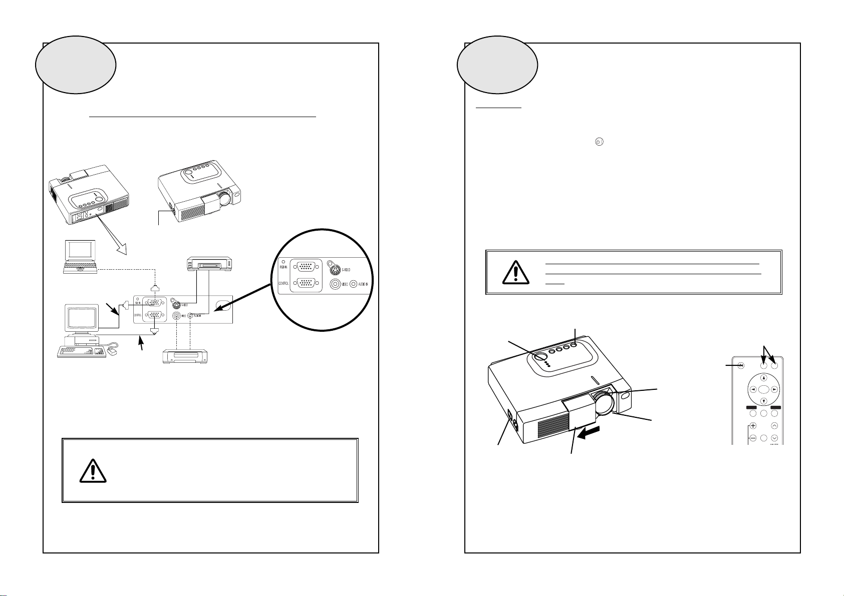
2 3
Example of interconnections with PJ-LC2001
Always install the projector in accordance with the safety
precautions contained in the Instruction Book
For full details of screen sizes and projection distances,
please refer to the Instruction Book
Switching On
1. Switch the power switch to on ( I ) and the projector will enter the standby mode
2. Press the Standby / On button ( ) on the control panel of the projector or remote
control and the power indicator will blink green while the projector warms up
3. When warm up is complete the light will light green permanently and you can open the
lens door
4. Select the input you require by using the video / RGB buttons on the remote control
(Input select)
5. Adjust the picture size and focus by use of the Zoom and focus controls on the lens
6. Press the standby button again to switch the projector off
Except in emergencies only switch the power switch off when the
Power Indicator is Orange, as doing so will shorten the life of the
Lamp
AC Inlet
DVD player / Satellite Receiver /
Video tape recorder with S jack
Video tape recorder / DVD player /
Satellite Receiver
Computer
(desktop type)
Computer
(notebook type)
RGB Cable
RS-232C Cable
Power Switch
Slide Lens door
STANDBY/ON Button
POWER Indicator
VIDEO
STANDBY/ON
POSITION
FREEZE
MAGNIFY
VOLUME
MENU
SELECT
RGB
MENU RESET
STANDBY/
ON Button
ZOOM knob
FOCUS ring
INPUT SELECT
 Loading...