

Hitachi PDV-302 Service Manual

ex.denom.com
SERVICE MANUAL
MANUEL D'ENTRETIEN
WARTUNGSHANDBUCH
CAUTION:
Before servicing this chassis, it is important that the service technician read the “Safety
Precautions” and “Product Safety Notices” in this service manual.
SM9100
PDV302
PDV302E
Data contained within this Service
manual is subject to alteration for
improvement.
ATTENTION:
Avant d’effectuer l’entretien du châassis, le technicien doit lire les «Précautions de sécurité»
et les «Notices de sécurité du produit» présentés dans le présent manuel.
VORSICHT:
Vor Öffnen des Gehäuses hat der Service-Ingenieur die „Sicherheitshinweise“ und „Hinweise
zur Produktsicherheit“ in diesem Wartungshandbuch zu lesen.
Les données fournies dans le présent
manuel d’entretien peuvent faire l’objet
de modifications en vue de perfectionner
le produit.
Die in diesem Wartungshandbuch
enthaltenen Spezifikationen können sich
zwecks Verbesserungen ändern.
SPECIFICATIONS AND PARTS ARE SUBJECT TO CHANGE FOR IMPROVEMENT
DVD Player
October 2004

ex.denom.com
PDV302 PORTABLE DVD PLAYER
WITH 7″ TFT DISPLAY
CONTENTS
Page
Specifications..................................................................................................................................................2
Block Diagram ................................................................................................................................................3
Disassembly Instructions................................................................................................................................4
TFT-LCD Driver Board Alignment ..................................................................................................................5
Troubleshooting..............................................................................................................................................6
Printed Circuit Boards.....................................................................................................................................7
Wiring Diagram.............................................................................................................................................10
Exploded View..............................................................................................................................................11
Mechanical Parts List....................................................................................................................................12
Electrical Parts List .......................................................................................................................................13
IC Lead Identification and Inte rnal Diag ram ................................................................................... ..............25
Voltage Cha rts ................................................................................................................ ..............................30
Schem atic Diagram ......................................................................................................................................35
ex.denom.com
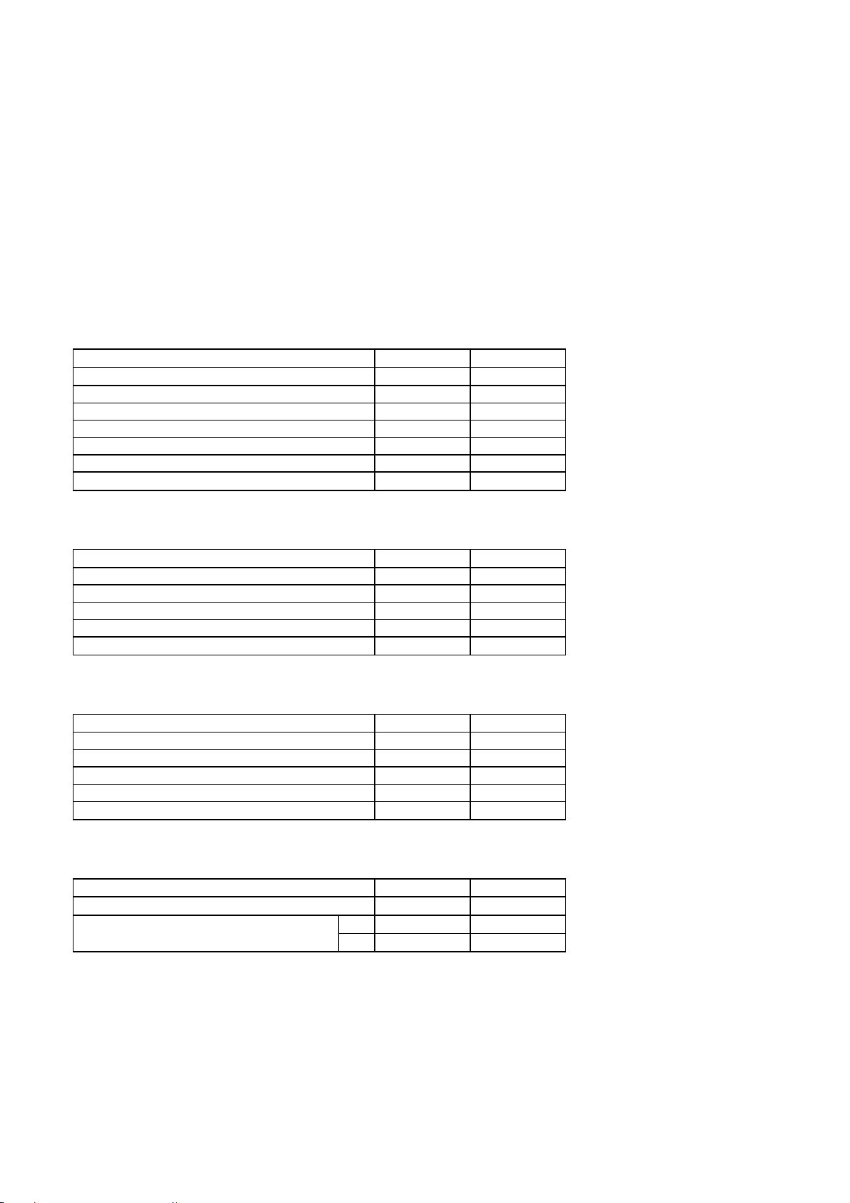
SPECIFICATIONS
DVD PLAYER SECTION
Laser Type : Semiconductor laser
Disc Diameter : 12/8 cm
Video Decoding : MPEG-2
Video DAC : 10 Bits
Video Formats : 4:3 / 16:9
Video Color System Format : NTSC, PAL
Audio DAC : 24 Bits / 96 kHz
Audio section
Item Unit Limit
Output level R/L (ch) mV
S/N Ratio (A-Weighted) dB 80
Dynamic range (A-Weighted) dB 80
Channel separation R/L (ch) (A-Weighted) dB 66
Distortion % 0.3
Optical digital output level V --Frequency response @ 20 / 20 kHz R/L (ch) dB
Speaker output
850 ± 100
0 ± 3
Item Unit Limit
10% Output power mW >700
S/N ratio (A-Weighted) dB 60
Channel separation R/L (ch) (A-Weighted) dB 55
Distortion % <1
Frequency response @ 100 / 20 kHz R/L (ch) dB
Headphone output
Item Unit Limit
Output power mW >30
S/N ratio (A-Weighted) dB 60
Channel separation R/L (ch) (A-Weighted) dB 55
Distortion % <1
Frequency response @ 100 / 20 kHz R/L (ch) dB
Headphone output
Item Unit Limit
C-Video output level Vp-p
S-Video output level
Y
C Vp-p
Vp-p
0 ± 6
0 ± 6
1.0 ± 0.1
1.0 ± 0.1
0.3 ± 0.1
2
3
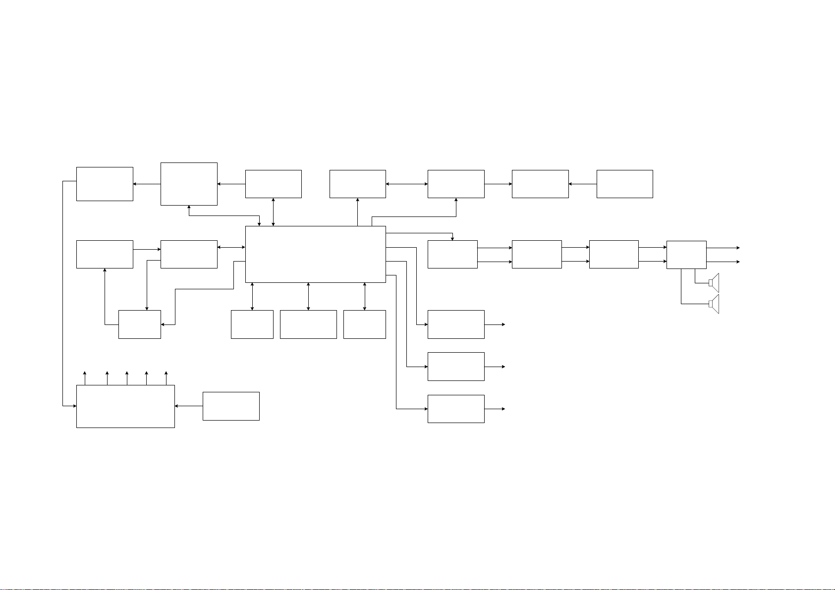
BATTERY AND
PROTECTED
CIRCUIT
DVD PICK UP
Vcc5V V3.3V
B+
AT1380AP
SWITCHING REGULATOR
CONTROLLER
AT5654
DRIVER
5V
CHARGING AND
-16V
+3V
BATT.
DISCHARGING
CONTROLLER
MT1336 E/C
ANALOG
FRONT END
12 V
SDRAM
AC ADAPTER
CT001
CPU
MCU + DECODING
MBM29LV800BA
MT1379 AE/C
RB5P006AM
VIDEO
PROCESSING
KEY
BOARD
Y2
Y3/Y4
CONTROL
CS4340 D/A
CONVERTER
IMPEDANLE
Y1
IMPEDANLE
IMPEDANLE
LZ9GJ24
TIMING
NET
NET
NET
DAC-ML
DAC-MR
OPTICAL/AUDIO-JACK
S-VIDEO-JACK
VIDEO-JACK
TFT
DISPLAY
F4558
PRE. AMP
INVERTER
BOARD
PT2257S
VOL.
CONTROL
BLOCK DIAGRAM
L
LM4863
R
AMP
PH-JACK
PH-JACK
SPK
SPK
ex.denom.com
ex.denom.com
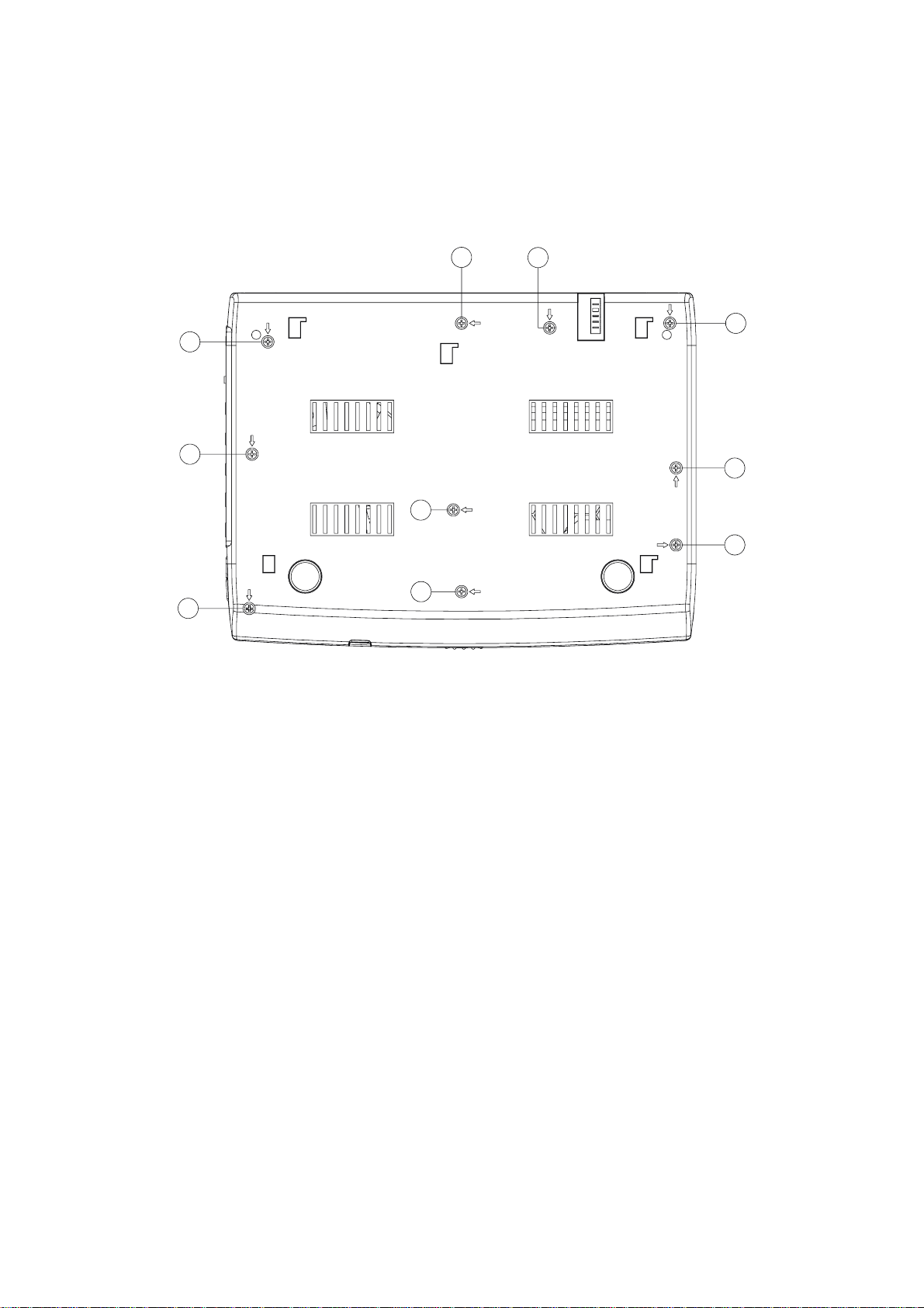
DISASSEMBLY INSTRUCTIONS
7
8
6
5
9
1
2
10
4
3
DETACH REAR CABINET FROM FRONT CABINET MUST REMOVE 10 SCREWS.
4

ex.denom.com
TFT-LCD DRIVER BOARD ALIGNMENT
OSC FREQUENCY ADJUSTMENT
1. Adjust the voltage of VR-OSC to -1.2 ∼ -1.6 V.
2. Turn off and turn on unit.
3. Measure the frequency between VD716 and R781 with X10 probe. It should be 19.8 ∼ 20 MHz,
and the value shoulb be steady comparatively.
VCO CHECK
Measure the frequency between X601 and X602 with X10 probe. at NTSC system, the frequency is
3.579545 MHz (±1 kHz), when change to PAL system by remote, the frequency is 4.433619 MHz
(±1 kHz).
IMAGE CENTER POSITION ADJUSTMENT
Playing VCD test disc, make the image locate ceter of TFT panel by adjustment VR-BCK.
DRIVER BOARD FUNCTION CHECK
1. Image reverse check:
press “reverse display” key on key board, the image on TFT panel can be 180º reversed.
2. NTSC / PAL switchover check:
switch NTSC / PAL system by remote, there are a abviously color change on TFT panel,
but the color change can not be colorless.
5

ex.denom.com
TROUBLESHOOTING
Item Symptom Cause and Remedy
1 No power
2 No picture
3 Distorted picture
4 Completely Distorted
picture
5 No color in picture (when
connects to TV)
6 Disc can’t be played
7 No sound
8 No return to start-up screen
when disc is removed
9 The player does not
respond to the remote
control
10 No audio at digital output
11 Buttons do not work
12 You have forgotten the
password
• Check if power plug is properly connected.
• Check if there is power at the AC outlet by plugging in another
appliance.
• Check if the TV is connected and switched on.
• Select the correct AV input on the TV.
• Check the video connection.
• Check channel selector is set to AV on the TV (See your TV
manual for instructions).
• Check the disc for fingerprints and clean with soft cloth, wiping
from centre to edge.
• Sometimes a small amount of picture distortion may appear.
This is not a malfunction.
• The disc is not formatted to the TV-set used (PAL/NTSC).
• The disc is not formatted to the TV-set used (PAL/NTSC).
• Ensure DVD Player is not connected through VCR.
• Ensure the disc is label side up.
• Clean the disc.
• Check if the disc is defective by trying another disc.
• Check audio connections.
• Make sure the sound setup of DVD disc is correct.
• Check to see if the program requires another disc to be loaded.
• Reset by unplugging the player from the power supply, the
connect the power supply again.
• Aim the remote control directly at the sensor on the front of the
player.
• Avoid all obstacles which may interfere with the signal path.
• Inspect or replace the batteries.
• Check the digital connections.
• Check the digital out menu to make sure that the digital output is
correctly set.
• Check if the audio format of the selected audio language
matches your receiver capabilities.
• Unplug the player from power outlet and reconnect after a few
seconds.
• The defaulted password is 6789.
6
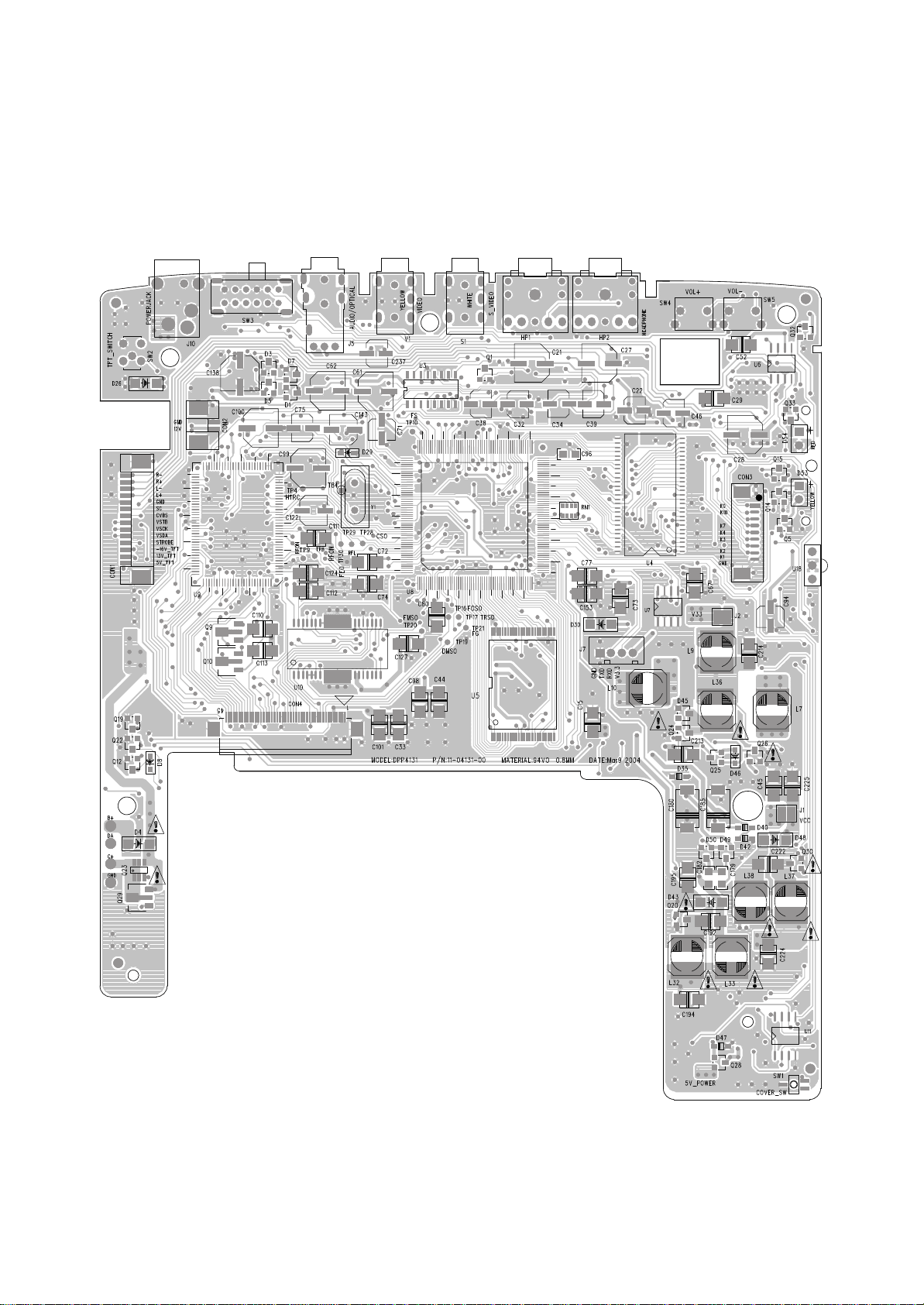
MAIN PCB (Top View)
ex.denom.com
PRINTED CIRCUIT BOARDS
7
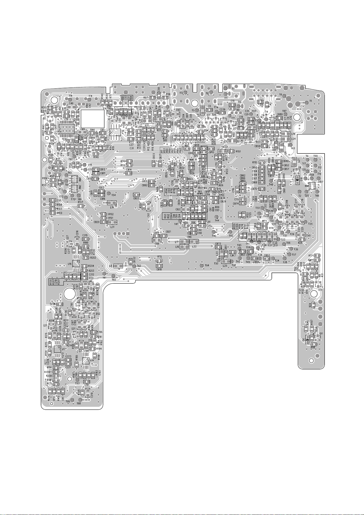
MAIN PCB (Bottom View)
ex.denom.com
8
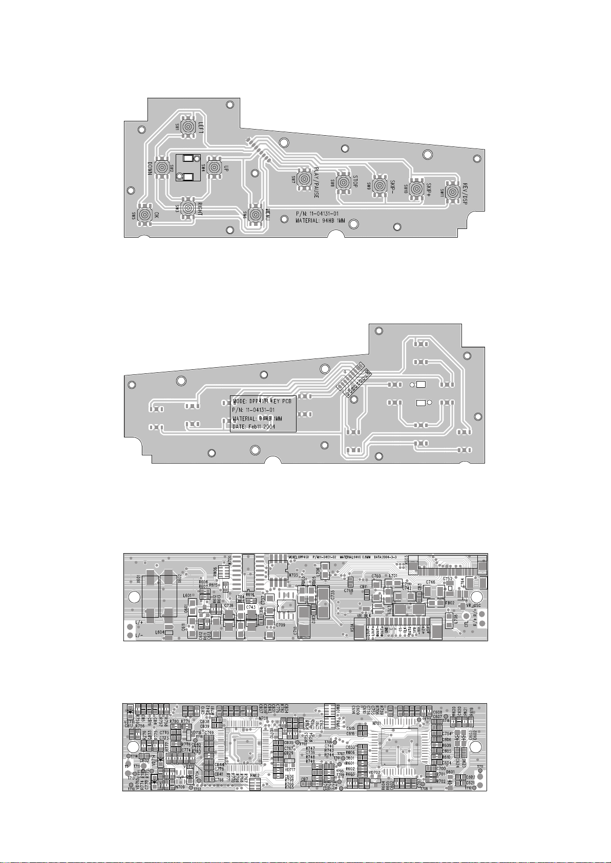
KEY PCB (Top View)
KEY PCB (Bottom View)
ex.denom.com
DRIVER PCB (Top View)
DRIVER PCB (Bottom View)
9
ex.denom.com
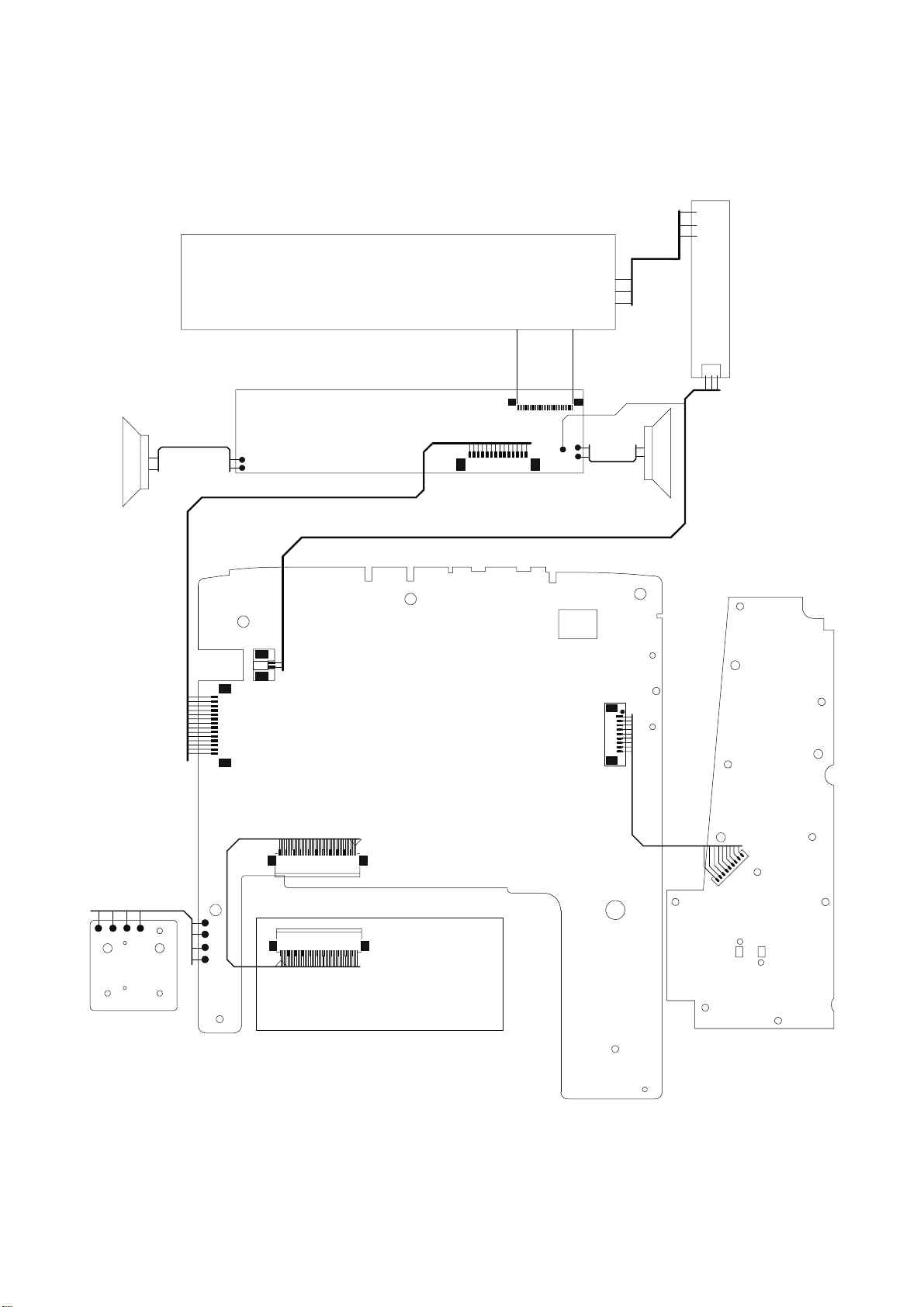
WIRING DIAGRAM
TFT - LCD
SPEAKER
P/N: 284060-02 UL1571#28
L/+
L/-
P/N: 20-73143-00 UL1517#30
P/N: 91-04011-00
DRIVER PCB
P/N.: 11-04131-02
XS1A
XS03
R/-
Y
C
CS
GND
LOUT-
ROUT-
LOUT+
ROUT+
CTL
R/+
+5V
STB
CLK
-16V
+13V
DATA
P/N: 20-84060-02
UL1571#28
SPEAKER
LAMP PCB
P/N.: 0 0-04131-01
CTL
GND
+12V
P/N: 20-73033-00 UL#28 P=1.25 L=170 mm
P/N: 25-83065-04 UL2468#24
BATTERY PCB
P/N: 11-04131-04
GND
+12V
CON2
LOUTLOUT+
ROUTROUT+
GND
C
Y
CS
CLK
DATA
STB
-16V
+13V
+5V
CON1
CON4
45
45P P=0.5 L=40 mm
P/N: 25-61020-45
B+
DA
C+
GND
1
DVD TRAVERSE MECH. SDR-083T
P/N: 98-04131-00
MAIN PCB
P/N: 11-04131-00
GND
CON3
K0
K10
K9
K7
K4
K3
K2
K1
KEY PCB
P/N: 11-04131-01
P/N: 20-53091-00 UL1571#30
D
N
1
G
K
2
K
3
K
4
K
7
K
9
K
0
1
0
K
K
J1
10
ex.denom.com
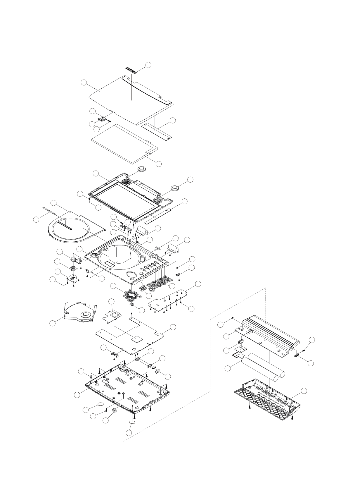
EXPLODED VIEW
1
2
3
4
6
54
32
5
53
7
13
12
15
16
17
18
20
14
25
8
9
51
10
11
19
21
22
24
50
49
43
40
39
38
52
48
47
46
45
44
23
37
41
42
29
30
31
33
36
35
26
55
27
28
55
11
34

ex.denom.com
MECHANICAL PARTS LIST
Ref. No. Description Qty
1 DPP4131 TFT Cover Top 1
2 DPP4131 TFT Open Knob Bracket 1
3 DPP4131 Open Slide Knob (For TFT Cover) 1
4 DPP4131 TFT Open Knob Spring 1
5 OP4011 TFT Sharp LQ070T5GG01 TFT Panel 1
6 DPP4131 TFT Cover Bottom (BS) ‘HITACHI’ 1
7
8 DPP4131 TFT Rubber Foot 2
9 Screw M3 X 5 BH/MS 2
10 Screw M2 X 5 BH/MS 1
11 Screw M3 X 4 BH/MS 2
12 DPP4131 CD Door Lens 1
13 DPP4131 CD Door 1
14 DPP4131 Middle Cabinet 1
15 DPP4131 Open Button 1
16 DPP4131 Open Button Lock 1
17 DPP4131 Lock Bracket 1
18
19 DPP4131 Adaptor For CD Door 1
20
21 DPP4131 Multi-Purpose Button 1
22 DPP4131 Heat Sink 1
23
24 DPP4131 LED Bracket 1
25
26 DPP4131 Bottom Cabinet (BS) ‘HITACHI’ 1
27
28 DPP4131 Remote Lens 1
29
30 DPP4131 Battery Case Top 1
31 4P Connector(F) P=2.5 250130FS 004G200ZU 1
32 Driver PCB 1
33 OP4131 Battery Pack DC=7.4V W/Protect Circuit 1
34 DPP4131 Battery Case Bottom (BS) ‘HITACHI’ 1
35 DPP4131 Slide Lock Knob 1
36 DPP4131 Slide Knob Spring 1
37
38
39 DPP4131 PCB Contact A Bracket 1
40 DPP4131 Multi-Purpose Button Bracket 1
41 DPP4131 Key PCB 94V0 1 mm 1
42
43 DPP4131 Volume Key +/- 1
44 DPP4131 Function 6 Button 1
45 DPP4131 TFT Stub Cover 1
46 DPP4131 Stud For TFT Cover 1
47 DPP4131 Shaft Cover ( R) 1
48 DPP4131 Damping Plate 1
49 DPP4131 CD Door Spring 1
50 DPP4131 Shaft Cover ( L ) 1
51 DPP4131 Rotating Shaft 1
52 OP4131 Inverter PCB ASS’Y 1
53
54 DPP4131 HITACHI Badge 1
55
Screw ∅1.7 X 5 KH/ST ‘Black’
Screw ∅2 X 6 KH/ST ‘Black’ (HD=3.8)
DPP4131 Slim DVD Traverse Mech SDR-083T (QSI) 1
DPP4131 Main PCB 1
Screw ∅2 X 8 BH/ST
Screw ∅2 X 6 BH/ST
Screw ∅1.7 X 3 KH/ST ‘Black’
4P Connector(M) P=2.5 250133MR 004G200ZU 1
Battery Contact PCB B 1
Screw ∅1.7 X 4 KH/ST ‘Black’
Speaker Cell 8Ω 1W ∅23 mm
XL-PG35 Rubber Foot ∅11.8 X 0.8 mm
9
3
8
4
2
18
2
2
12
 Loading...