

Page 1
8
PDV-1021S
Caution
Be sure to read this manual before servicing. To assure safety from fire, electric shock, injury harmful radiation
and materials, various measures are provided in this Hitachi protable DVD player.
Be sure to read the cautionary items described in the manual to maintain safety before servicing.
Service warning
1. Do not attempt to modify this product in any way and never perform customized installations without manufacturer’s approval. Unauthorized modifications will not only void the warranty,but may lead to your being
liable for any resulting property damage or user injury.
2.
Service workshould be performed only after you are thoroughly familiar with all of the following safety checks and servicing guidelines. To do otherwise,increase the risk of potential hazards and injury to the user.
3.
While servicing,use an isolation transformer for protection from A.C. line shock.
Contents
*
* SAFETY NOTICE....................................................2
* PRODUCT SPECIFICATIONS.................................3
* FUNCTIONAL OVERVIEW..................................4-6
* CONNECTIONS....................................................7-8
*
WIRING DIAGRAM .............................................9
PCB WIRING DIAGRAMS.........................................10-12
*
BLOCK DIAGRAM...............................................13
*
SCHEMATIC DIAGRAMS....................................14-17
TROUBLESHOOTING........................................18-20
*
* REPLACEMENT PART LIST........................................21-36
SPECIFICATIONS AND PARTS ARE SUBJECT TO CHANGE FOR IMPROVEMENT
Protable DVD player
Dec. 2005 Digital Media Systems Group, Hitachi Asia Ltd.
Page 2
SAFETY NOTICE
LASER BEAM CAUTION LABEL
When the power supply is being turned on, please don’t remove this laser cautions label. If it removes, radiation of laser
may be received.
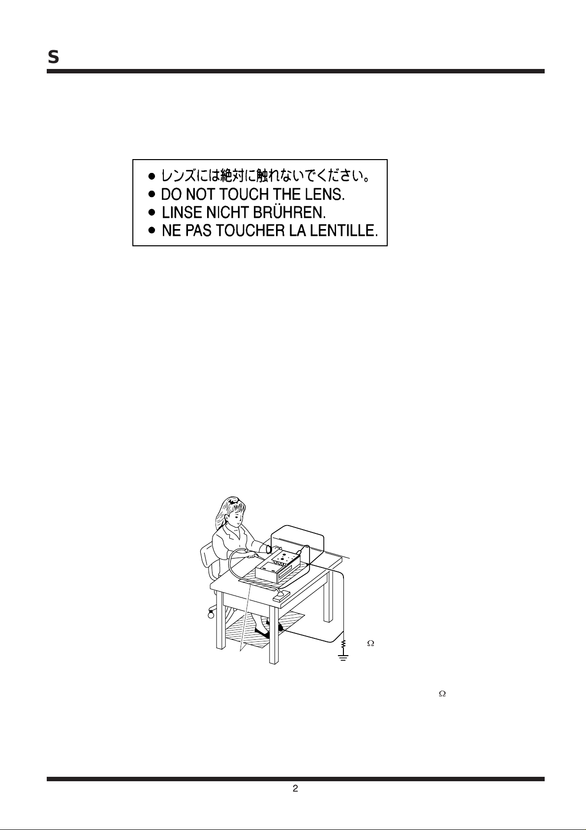
PREPARATION OF SERVICING
Pickup Head consists of a laser diode that is very susceptible to external static electrocity.
When replacing, please use a conductive mat, soldering iron with ground to protect the laser from damaged
by static electricity.
Please apply the same procedure when repair IC.
Ground conductive
wrist strap for body.
Soldering iron
with ground wire
or ceramic type
1M
Conductive mat
The ground resistance
between the ground line
and the ground is less than 1M
2
Page 3

PRODUCT SPECIFICATIONS
Laser Wavelength
Video System
Frequency Response
Signal/noise Ratio
Audio Distortion + Noise
Channel Separation
Dynamic Range
Output
Audio Output (Analogue Audio)
Digital Output (Digital Audio)
Video Output
650nm
PAL/AUTO/NTSC
20Hz ~ 20kHz (+/-1.0dB)
>= 95 dB
<= -80 dB (1kHz)
>= 85 dB
>= 85dB
Output Level: 2V +/- 10%
Load Impedance: 10 k ohm
Output Level: 0.5Vp-p
Output Level: 1Vp-p +/- 20%
Load Impedance: 75 ohm
Operating Temperature Range
Power Supply
Power Consumption
Dimension (WxHxD)
Weight
o
5~35
C
DC 9V 2.2A
<= 20W
257 x 32 x 169 mm
1.2kg
3
Page 4
FUNCTIONAL OVERVIEW
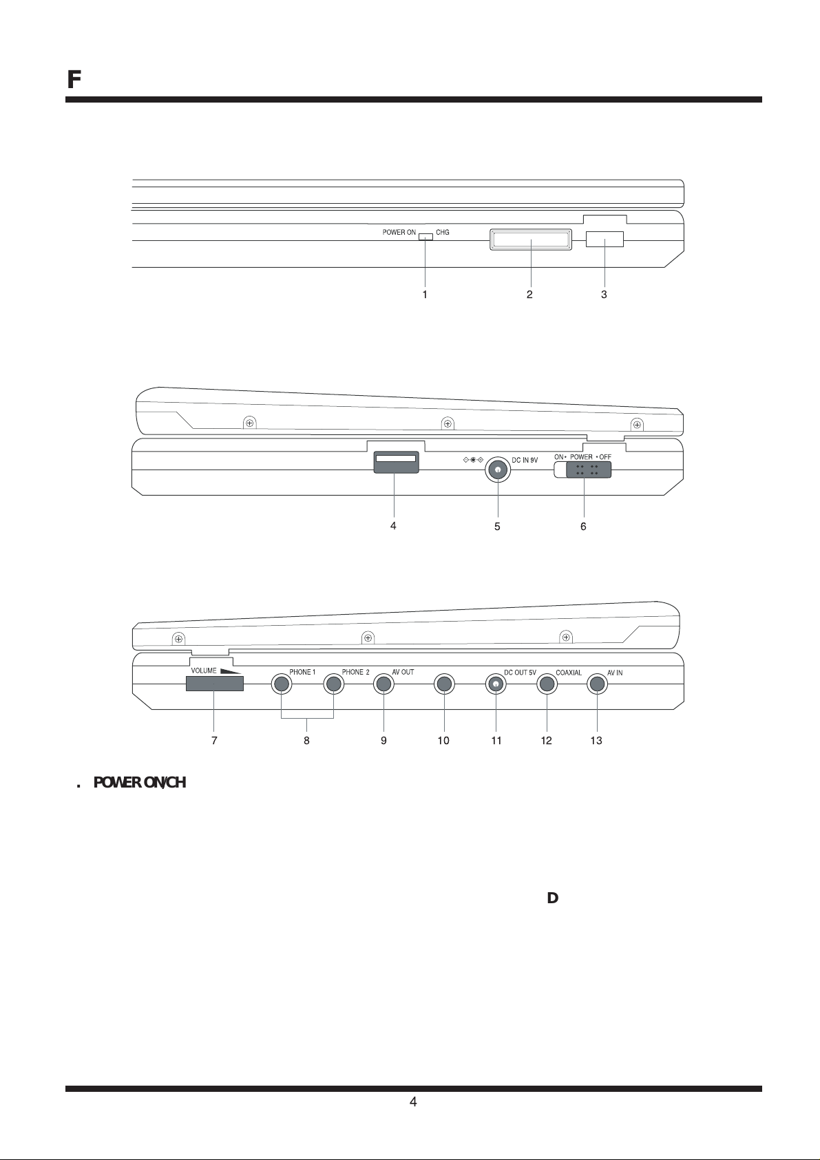
Front of Player
CARD SLOT
Left of Player
Right of Player
USB MEMORY
4
1
COMPONENT VIDEO/
PROGRESSIVE SCAN OUT
2
5
3
6
1. POWER ON/CHG
Power and charging indicator.
2. CARD SLOT
Memory card slot.
3. REMOTE SENSOR
4. USB MEMORY
USB port
.
5. DC IN 9V
Power supply jack.
6. POWER ON / OFF
Turn the player on or off.
1378910 1211
7. VOLUME
Volume control.
8. PHONE 1 & 2
Earphone jacks.
9. AV OUT
10. COMPONENT VIDEO / PROGRESSIVE
SCAN OUT
11. DC OUT 5V
12. COAXIAL
Digital audio output jack.
13. AV IN
4
Page 5
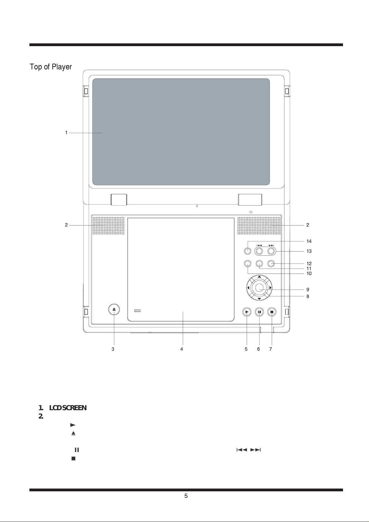
Top of Player
1
2
34567
2
14
13
12
11
10
9
8
1. LCD SCREEN
2. SPEAKER
5. PLAY ( )
3. OPEN ( )
4. DISC DOOR
6. PAUSE ( )
7. STOP ( )
8. DIRECTION BUTTONS
9. ENTER
10. MONITOR
11. USB/CARD
12. MENU
13. PREV/NEXT ( / )
14. SOURCE
5
Page 6
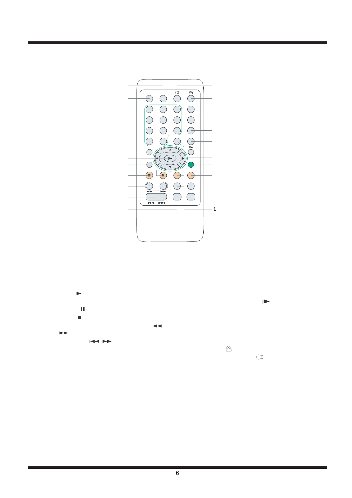
Remote Control
1
2
3
4
5
6
7
8
9
10
11
OSD SUBTITLE
123
456
987
10/0 +10
SETUP
TOP
MENU
ZOOM MUTE
REPEAT A-B
AUDIO MODE DIGEST
HITACHI
PDV-RM701
PLAY MODE
RESUME
TIME SEARCH
CARD/USBRETURN
MENU
26
25
24
23
22
21
20
19
18
17
16
15
14
13
12
1. SUBTITLE
2. OSD (ON-SCREEN DISPLAY)
3. NUMBER BUTTONS
4. SETUP
5. PLAY ( )
6. TOP MENU
7. PAUSE ( )
8. STOP ( )
9. FAST BACKWARD/FAST FORWARD (
/ )
10. PREV/NEXT ( / )
11. AUDIO MODE
12. REPEAT
13. DIGEST
14. REPEAT A-B
15. MUTE
16. ZOOM
17. MENU
18. DIRECTION BUTTONS
19. SLOW-MOTION PLAY ( )
20. RETURN (not applicable to this player)
21. CARD/USB
22. TIME SEARCH
23. RESUME
24. PLAY MODE
25. ANGLE ( )
26. AUDIO LANGUAGE ( )
6
Page 7
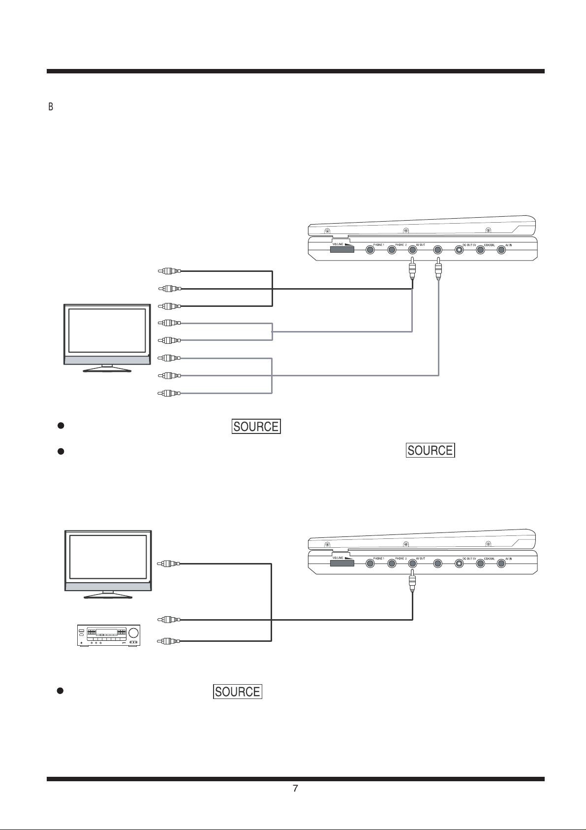
CONNECTIONS
Before using the player, you may connect the player to a TV and/or an amplifier, a video game console or an optional TV tuner.
NOTE:
Turn off the power supply to the player and the equipments before making any connection.
Connecting to a TV
COMPONENT VIDEO/
PROGRESSIVE SCAN OUT
To Video Input (Yellow)
TV
To Audio (R) Input (Red)
To Audio (L) Input (White)
To Audio (R) Input (Red)
To Audio (L) Input (White)
To Y
B/PB
To C
To CR/PR
To AV OUT (Black)
.
.
.
OR
.
.
.
.
.
To AV OUT (Black)
To COMPONENT VIDEO/
PROGRESSIVE SCAN OUT (Black)
NOTE:
For connection through AV OUT, Press button repeatedly to select AV out when you turn on the player.
For connection through COMPONENT VIDEO / PROGRESSIVE SCAN OUT, Press button repeatedly
to select YC
BCR or YPBPR out when you turn on the player.
Connecting to a TV and an Amplifier
COMPONENT VIDEO/
PROGRESSIVE SCAN OUT
TV
To Video Input (Yellow)
Amplifier
To Audio (R) Input (Red)
To Audio (L) Input (White)
To AV OUT (Black)
NOTE:
When you turn on the player, press button repeatedly to select AV OUT.
7
Page 8
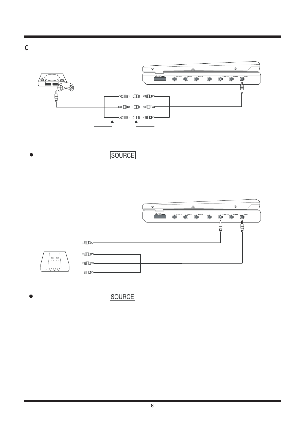
Connecting to a Video Game Console
Game Console
(Yellow)
(Red)
(White)
Female to Female RCA Adaptor (not supplied)AV cable (supplied with game console)
To AV Output
(Yellow)
(Red)
(White)
NOTE:
When you turn on the player, press button repeatedly to select AV IN.
Connecting to an Optional TV Tuner
COMPONENT VIDEO/
PROGRESSIVE SCAN OUT
COMPONENT VIDEO/
PROGRESSIVE SCAN OUT
To AV IN (Black)
TV Tuner
To DC IN 5V
To Video Input (Yellow)
To Audio (R) Input (Red)
To Audio (L) Input (White)
NOTE:
When you turn on the player, press button repeatedly to select AV IN.
To DC OUT 5V
To AV IN (Black)
8
Page 9
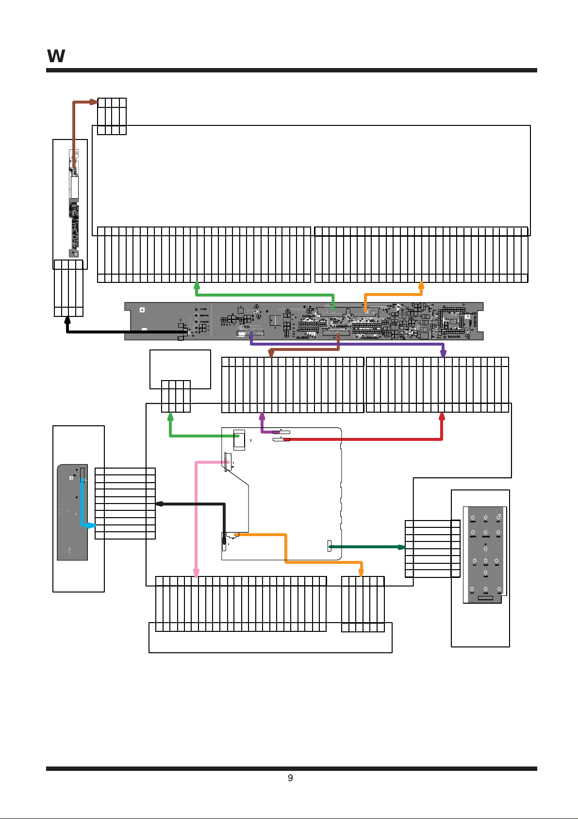
WIRING DIAGRAM
123
4
GND
GND
ISEN
VSEN
123
4
LCD
HV PCB
123
TFT-GND
BRIGHT-CON
TFT ON/OFF
123
XS1
POWER
302928272625242322212019181716151413121110 9 8 7 6 5 4 3 2
4
VCOM
GND
A VDD 8.8V
V11T
V9T
V7T
V5T
V3T
V1T
R/L
BLU0
BLU1
BLU2
BLU3
BLU4
BLU5LDSTHR
LCD VDD
DCLK1
GND
302928272625242322212019181716151413121110 9 8 7 6 5 4 3 2
123
BATT+TSGND
123
XS003
XS2
4
GND
4
1 2 3 4 5 6 7 8 910111213141516171819
BATTERY
BLU0
BLU1
BLU2
BLU3
1 2 3 4 5 6 7 8 910111213141516171819
XS2
HV/9V
4
SWITCH
PCB
XS5
10
9
8
7
6
5
4
3
2
1
USBVDD
10
USBM
9
USBP
8
DC
7
XS3
DC
6
DCIN
5
GND
4
GND
3
GND
2
POWER SW
1
242322212019181716151413121110 9 8 7 6 5 4 3 2
INV
STHL
BLU4
GRN0
BLU5
GRN1
GRE0
GRE1
XS10
GRN2
GRN3
GRE2
GRN4
GRE3
GRE4
1
302928272625242322212019181716151413121110 9 8 7 6 5 4 3 2
GND
RED0
RED1
RED2
RED3
RED4
RED5
GND
V2T
V4T
V6T
V8T
V10T
A VDD 8.8V
GND
VCOM
U/D
V13T
+16V
V14T
-10V
V12T
XS4
SPKL+
SPKR-
XS6
8
7
6
5
4
3
2
1
SPKR+
GND
LCD VDD
GND
GRN5
GND
1
302928272625242322212019181716151413121110 9 8 7 6 5 4 3 2
XS3
XS5
1 2 3 4 5 6 7 8 910111213141516171819
20
GRE5
RED0
RED1
RED2
RED3
RED4
RED5
GND
OE
CPV
POLLD-14.5V
STV
+16.5V
GND
GND
5.5V
5.5V
SPKL-
KEYIN3
KEYIN2
KEYIN1
KEYIN0
KEYOUT0
KEYOUT1
KEYOUT2
KEYOUT3
1
1 2 3 4 5 6 7 8 910111213141516171819
20
MAIN PCB
XS008
1 2 3 4 5
6
XS1
8
7
6
5
4
3
2
1
GND
GND
IF PCB
TFT ON/OFF
BRIGHT-CON
STV1\DIO1
1
CPVOESTV2\DIO2
POL
1
20
TFT-HV9V
TFT-HV9V
20
NC
LD/VCC
V20
GNDFE
CD/DVD SWRFCDBAVRCD
242322212019181716151413121110 9 8 7 6 5 4 3 2
VRDVDMDLD/CD
GND
LD/DVDNCVCC
FCS-
TRK+
9
TRK-
FCS+
1
LIMIT
GND
SL-
SL+
1 2 3 4 5
SP+
SP-
6
MECHANISM
FUNCTION
BUTTON
PCB
Page 10
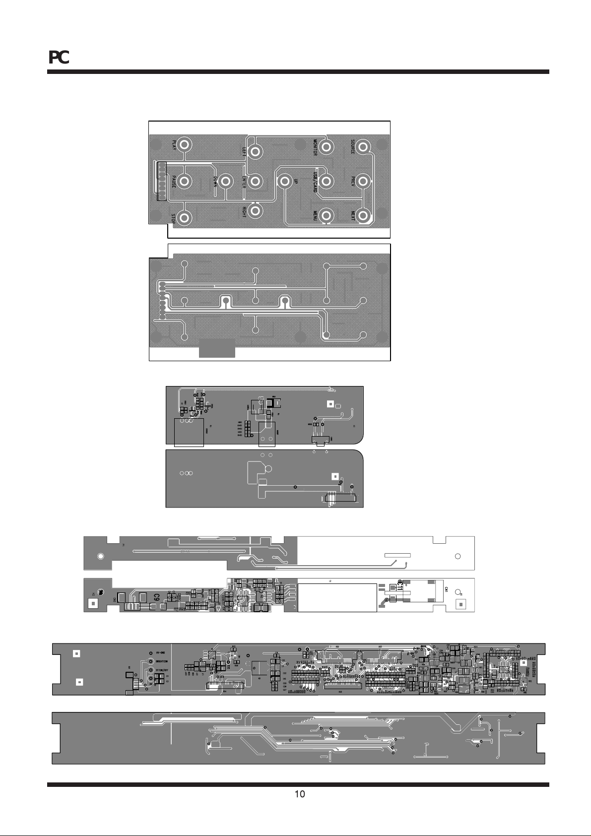
PCB WIRING DIAGRAMS
FUNCTION BUTTON PCB
POWER SWITCH PCB
HV PCB
IF PCB
10
Page 11
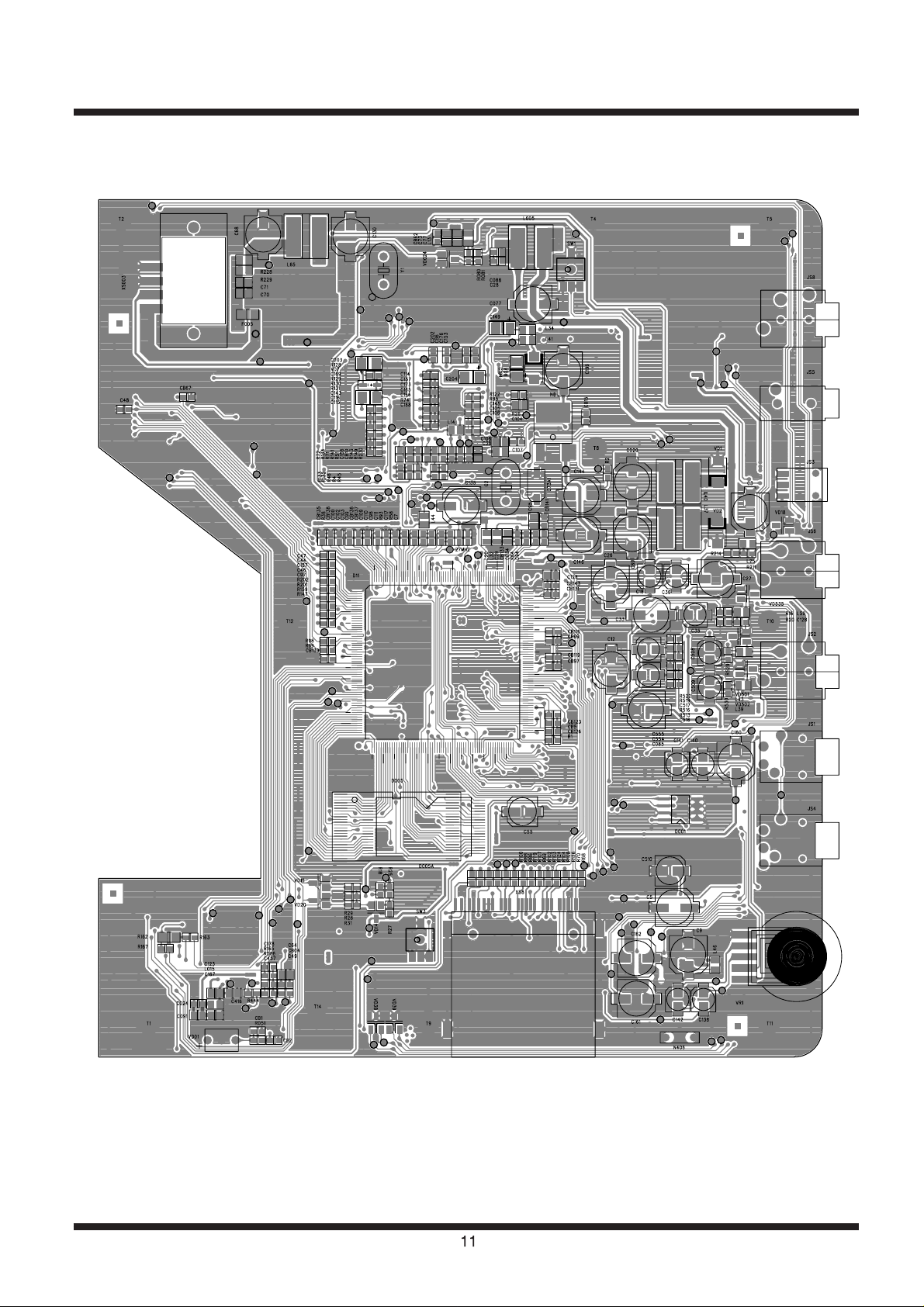
MAIN PCB (TOP)
11
Page 12
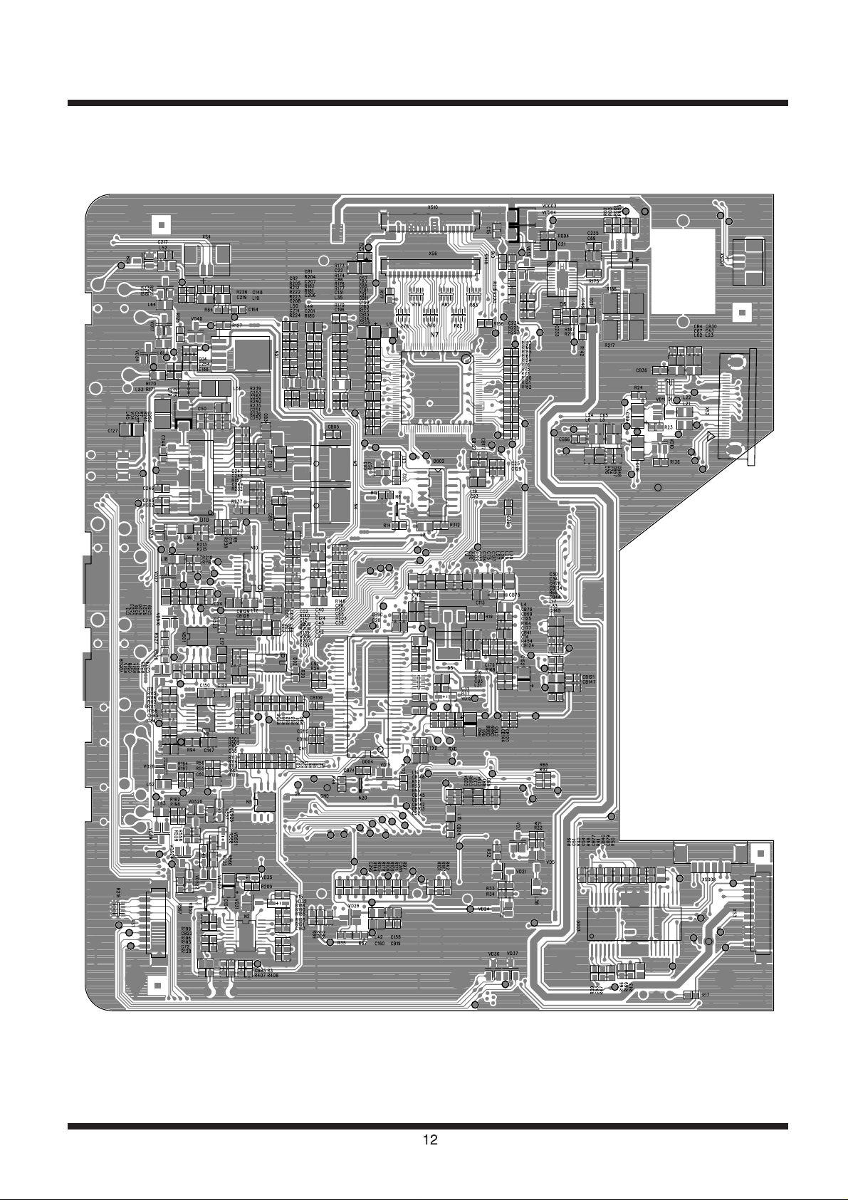
MAIN PCB (BOTTOM)
12
Page 13

BLOCK DIAGRAM
OSCILLATOR
OZ9RR
HIGH VOLTAGE ASS'Y
DC 9V
VIDEO IN
USB/CARD
BPR/
YP
BCR
YC
VIDEO OUT
COAXIAL OUT
AUDIO OUT
AUDIO IN
PHONE OUT
SPEAKER LOUT
SPEAKER ROUT
27MHz
27MHz
74HCU04
64M SDRAM
HY57V641620ETP-H
TFT MONITOR
UPD5300
+5V
+3.3V
+1.8V
BA7660
AUDIO AMP
(AZ4558)
L
AUDIO D/A
(PCM1753)
TFT POWER
+3.3V +5V +2.5V 8.8V +16V -10V
AUDIO +5V
L
R
R
AUDIO +/-5V
BATTERY
74LV4052PW
DC / DC
HWD4863
(VG202C)
(TPC8207)
(BQ2057C)
16M FlashROM
MX29LV160ABTC-70
TC4W53
RF AMP & SERVO & DVD PROCESSOR
MPEG-2 DECODER & VIDEO ENCODER
MT1389DE
DV23(HD80)
PU mechanism
+5V
DRIVER +5V
DRIVER
(CMD5954)
13
AC
100~240V
50/60Hz
Adapter
DC IN +9V
Page 14

SCHEMATIC DIAGRAMS
MAIN PCB CIRCUIT DIAGRAM 1
CB74
100N
5
1
4
32
FMC3
N20
R172
10k
R44
10K
VD15
KTA1298
TFTONOFF
TFTON
C146
+P5V
R3
10
193
FS
194
VREF
195
196
197
198
199
GPIO_4
200
GPIO_3
201
202
203
SPMCLK
204
SPDATA
205
SPLRCK
206
SPBCK
207
DVDD3
208
ALRCK
209
ABCK
210
ACLK
211
212
DVDD18
213
214
215
SPDIF
216
217
218
219
220
221
222
223
224
AVCM
225
226
227
228
229
230
231
232
XTALO
233
XTALI
234
JITFO
235
JITFN
236
PLLVSS
237
238
239
LPFON
240
LPFIP
241
LPFIN
242
LPFOP
243
244
ADCVSS
245
RFVDD3
246
247
RFRPAC
248
HRFZC
249
CRTPLP
250
RFGND
251
OSP
252
OSN
253
RFGC
254
IREF
255
AVDD3
256
V20
100U/16V
+
CB05
100N
C016
100N
CB65
100N
C84
100N
C25
100N
C129
100N
CB36
100N
Y7
HSY
DCLK
GND
DACVDDB
GND
CVBS
DACVDDB
GND
188
184
183
190
186
187
191
189
185
192
YUV5/B
YUV1/Y
YUV2/C
YUV4/G
YUV0/CIN
DACVSSB
DACVSSA
DACVSSC
DACVDDB
DACVDDA
YUV3/CVBS
DACVDDC
ASDATA0/GPO_2
RVREF/GPIO_6
RCLKB/GPIO_5
ASDATA1/GPO_1
ASDATA2/GPO_0
ASDATA3
ASDATA4
MC_DATA
APLLVDD3
APLLCAP
APLLVSS
ADACVSS2
ADACVSS1
ARF(SW)
ARS/SDATA3
AR/SDATA1
AL/SDATA2
ALS/SDATA0
ALF/(CTR)
ADACVDD1
ADACVDD2
RFGND18
RFVDD18
IDACEXLP
PLLVDD3
ADCVDD3
RFRPDC
DVDA
DVDB3DVDC4DVDD5AGND
DVDRFIP6DVDRFIN7MA8MB9MC10MD11SA12SB13SC14SD15CDFON16CDFOP17TNI18TPI19MDI120MDI221LDO222LDO1
2
1
DVDA
GND
DVDD
$$$251
DVDB
DVDC
#MA
$MDMC#MB
CD/DVD
R24
1k
E
F
MD
Y4
DVSYNCY5Y6
XS1
SD-DATA1#BR
SD-DATA2#
SD-DATA3#
KEYIN1
GND
SD-DATA0#GV18
KEYIN0
181
179
180
178
177
182
176
175
174
YUV7
DVSS
IO_17
YUV6/R
C0/IO_0
C1/IO_1
VSYNC/V_ADIN1
HSYNC/V_ADIN2
MT1389DE
MD
E
F
+
C30
10U/10V
VCC
COMMON2INH3VEE4VSS
1
5A6
8
L02 601L23 601
CH17CH0
VDD
C43
10U/16V
CB30
100n
PAL/NCSY0
1234567
MOLEX-0890
KEYIN0
KEYIN1
KEYIN2
DV33
KEYIN3
KEYIN2
KEYOUT0
173
172
171
170
DVDD3
C2/IO_2
C3/IO_3
C4/IO_4
DVDD18
Pin Assignment v1.5
SVDD3
23
24
SVDD3
$$$60
$$$59
CB67
100n
C67
10U/16V
CB4
100n
D1
TC4W53
XS2
+P5V
R138
10
C72
10U/16V
CB85
100N
1
2
3
N406
HS0038B
R407
10K
NC
R408
IR
$$$243
FS
VREF
DACVDDB
SD-CLK#
MS-DATA3#
MS-DATA2#
MS-DATA1#
MS-DATA0#
MS-BS#
MS-CLK#
MS-CD#
SD-CD#
TFTSW
DVD/AUX#
DV33
ALRCK
ABCK
ACLK
SD-CMD#
V18
BAT-DET
$$$7
SPDIFOUT
L3 601
DV33
100N
C90
GND
10U/16V
C133
ASDATA0
$$$67
GND
$$$8
10U/16V
C137
27M
750K
R93
100P
C117
100N
GND
100N
C111
C98
$$$259
47N
C110
47N
C109
$$$280
C39
20P
GND
$$$281
1N
C102
100N
C103
33N
C102
GND
100N
15K
C100
R38
100N
CB138
AVDD3
100N
CB135
100N
CB76
601
L30
SVDD3
$$$101
+P5V
L19
601
100n
CB127
CB117
100n
+
C93
10U/16V
13
14
12
6A
6Y
VCC
1A11Y22A32Y43A53Y6GND
D002
74HCU04
C61
22P
C63
1N
G2
27M
C73A1
TZC03A200P
R57
1M
8
KEYIN3
KEYOUT0
KEYOUT1
KEYOUT2
KEYOUT3
DV33
MA5
MA4
5300RESET
KEYOUT3
KEYOUT1
CS
KEYOUT2
166
169
167
168
165
C5/IO_5
C7/IO_7
C6/IO_6
Y0/IO_9
YUVCLK/IO_8
V2REFO28SGND27VREFO30V2029TEO32FEO
RFLVL/RFON26CSO/RFOP25TEZISLV33OP_OUT34OP_INN35OP_INP36FOO42TRO41VPLLVDD3
GND
V2P8
V20
FMO
C179
100n
0
R168
LD/VCC
GNDFE
V20
MA7
V18
MA6
163
Y1/IO_10
31
CB139
162
Y2/IO_11
100N
DVDA
C47
CD/DVDSWRFC/C
161
Y3/IO_12
C46
1uF
160
Y4/IO_13
OPO
DVDD
1uF
$MD
DVDD18
987654321
159
158
157
Y5/IO_14
Y6/IO_15
37
OP-
OP+#
#DMSO
#MA
R202
0
DVDB
C44
1uF
R201
R147 0
D/D
B/B
A/A
155
154
153
152
156
RA4
RA5
RA6
RA7
DVDD3
Y7/IO_16
TROPENPWM39PWMOUT1/V_ADIN940USB_VSS
FMO38DMO
FMO
TRO
F00
C97
C48
4700P
MC
0
R159
LDOVCC
DVDC
0
C187 1uF
+
C119
10U/16V
R99
R23
10
L22 601
VD/CD
VR/DVDMDLD/CD
GND
MA8
151
43
GND
NC
LDO1
VD11
LD/DVD
RA8
VPLLVSS
4.7
164
V1P4
VD9
DTC144
$$$9
L53 601
R171
100
R170
33
SPDIFOUT
33
C188
R312
33
9
11
10
4A
5A
5Y
C62
22P
R58
10
MA9
MA11
DCLK
DV33
MA3
DCKE
GND
149
150
144
148
146
147
145
RA9
CKE
RA11
DVSS
RCLK
DVDD3
CAPPAD44USBP47USBM48USB_VDD349FG/V_ADIN850TDI/V_ADIN4
45
46
GND
#USBP
#USBM
$$$82
$$$41
$$$55
R163
150K
LDO2
R98
4.7
C118
10u/6v
+
10
R136
VD10
KTA1298
KTA1298
L21
601
F-
T+
T-
F+
VCC
242322212019181716151413121110
8
4Y
7
C75
MA2
143
RA3
51
5.1P
V18
MA1
141
142
RA2
RA1
DVDD18
TMS/V_ADIN5
TCK/V_ADIN653TDO/V_ADIN754DVDD1855IOA2
52
CLOSESW
STBY
OPO
R164
R165
680K
MOLEX-2490
27M
$$$169
$$$231
$$$138
R5333
R5233
MA10
MA0
139
140
136
138
137
BA1
BA0
RA0
RA10
RCS#
IOA357IOA4
56
58
V18
A2
A3
A4
C177
2N2
680K
R43
14
VOFC+
VOTK+
15
T-
0R5
R50
V1P4
2N2
C178
R162
1
R167
150K
SL-
SP+
SP-
6
XS008
SDRAM3V3
L16
601
C52
10U/16V
+
CB103
100n
CB110
100n
CB115
100n
CB109
100n
100n
CB146
$$$140
$$$142
$$$147
RN522*4
DQM1FGLIMIT
DV33
DQ8
132
130
129
134
135
133
131
RD8
CAS#
RAS#
IO_18
DQM1
RWE#
DVDD3
IOA5
HIGHA062IOA18
IOA19
IOA660IOA7
59
63
64
61
A5
A6
A7
$$$201
A18
A19
R444
10K
DMSO
R169
100n
CB40
R168
10k
0R5
OP+
29
8
9
10
11
12
13
7
G1
VCC
PGND
VOSL-
VOSL+
VOFC-
PVCC1
VNFFC
PVCC221PGND19VNFTK20CTK224BIAS
VOLD+17VOLD-18VOTK-16VINLD23PREGND22CTK125VINTK
G2
30
SL-
T+
SL+
DRVCC1
CB79
100n
+
C123
10U/16V
+
C416
10U/16V
601
L015
DRVCC
SL+
R1
10k
12345
53261-0690
DV33
C34
10U/16V
CB124
C60
+
CB123
CB126
CB97
CB99
CB121
CB147
CB144
CB120
CB88
CB142
C8
+
+
10U/16V
CB24
100N
DV33
TFTON
R192
1k
+P5V
VD25
ISS355
VD17
STZ6.2N
L64
RIN
MUTE
VD510
2SD601AR
L43
601
300P
C518
R515
10k
ML
R62
R63
33
15
14
ML
SCK
BCK1DATA2LRCK3DGND
ALRCK
C12
ASDATEO
10U/16V
CB128
100n
10U/16V
100N
100N
100N
100N
100N
100N
100N
100N
100N
100N
10U/16V
VD26
601
MD#
33
DTA124
A-R
R59
MD13MC
4
+
100U/16V
CB129
100n
CB89
100n
CB5
100n
CB119
100n
C20
10U/16V
CB90
100N
R19
22
CB116
100N
V18
123
D3
R155
220uF/4V
+
1
C509
2
XS003
Speaker
30k
R176
SPVDD
100k
R185
R161
10k
R190
100k
+
R160
10k
C36
10U/16V
ARR2
R116
10k
C13
R115
1k
10U/16V
33
R11
DVD/AUX
R94
100N
C147
10U/16V
+P5V
10
R158
R112
10k
R111
1K
A-L
AUDIO-5V
R593
4R7
R530
100
C17
C13
10U/16V
C509
10U/16V
47uF/4V
+
C523
1
C574
100n
4558
4
N501A
3
2
R517
10k
R523
R514
3k9
C516
1N8
6K8
R513
R516
100k
C554
+
47U/4V
DV33
R502
47K
10K
C555
47U/4V
+
R01
10k
10K
R49
R501
47K
L-MAIN
$$$116
8
11
7
12
LOUT
ROUT
ZERONA
ZERO OA
R556
1k
+3.3V5+5V
GND9VCOM
6
10
$$$63
C58
100n
4R7
L26
+
C59
10U/16V
100n
+P5V
JS2
V18
L31 601
DV33
C11
1V8
4
LT1117-1.8V
L63
R155
1k
+P5V
10
L46 601
N2
11
12
13
14
15
16
17
18
19
20
VD4
2SD601
+
9
10
11
12
13
14
15
16
VD17
STZ6.2N
LIN
A-R
+P5V
R529
100
R518
100
+
C508
47uF/4V
100n
7
N501B
4558
8
5
6
10k
R521
3k9
R519
6K8
+P5V
R558
10k
VD525
ISS355
CB3
100N
10U/16V
C10
10U/16V
JS1
601
C150
+
C120
100U/6.3V
+
NC
NC
+IN B
-IN B
-OUT B
VDD
+OUT B
GND
HP-IN
R149
1k
VR1
WX10HB-2-20K
B
A
3X
0X
1X
2X
VDD
L60
R520
C517
1N8
100k
R522
VD524
KTA1298
R557
4R7
100U/6.3V
BYPASS
N9
601
VD510
10k
HSJ1594-010065A
1
2!ROUT
7
3
VOUT
VD502
STZ6.2N
601
L39
A-L
JS4
HSJ1494-01010
HSJ1494-01010
2
4
2
VD29
STZ6.2N
VD28
STZ6.2N
601
L62
1k
R194
10
R197
C162
220uF/4V
+
C166
330N
N4863
CB22
100n
+
C9
100U/16V
R125
VR2
VSS
VEE
INH
1Y
3Y
X-COM
TC4052
Y-COM
2Y
0Y
2SD601
R527
1k
C519
300P
R567
100
$$$9530 MUTE
R559
4k7
VD520
2SD601
NC
10
NC
9
+IN A
8
GND
7
-IN A
6
-OUT A
5
VDD
4
+OUT A
3
GND
2
SHUTDOWN
1
$$$264
0
R199
VD14
1k
WX10HB-2-20K
C150
10U/16V
8
7
6
5
4
3
2
1
R95
1k
R526
1k
VD522
ISS355
VD33
+
2
SPL-
1
SPL+
XS001
Speaker
R196
30k
R197
10
+
C147
10U/16V
2SD601
ALL2
C141
10U/16V
+
C122
100N
+
R117
10
-5V
R113
1K
R114
10k
R120
10k
A-L
VD509
2SD601
VD407
KTA1298
R560
470
+P5V
VD521
ISS355
ISS355
C510
47U/6V
+
C5
R568
100k
100U/16V
+
CB78
100N
CB134
100N
C125
DV33
C41
10U/16V
+
VSS
VSS
VSSQ
52
VSSQ
VSS
46
VSSQ
12
NC
VSSQ
6
NC
VCCQ
CB145
100n
49
DQMH
VCCQ
43
VCCQ
DQML
9
VCCQ
3
CB111
100n
DQ15
DQ14
DQ13
DQ12
DQ11
DQ10
DQ9
DQ8
DQ7
DQ6
DQ5
DQ4
DQ3
DQ2
DQ1
DQ0
D11
MT1389DE
RD9
128
RD10
127
RD11
126
RD12
125
RD13
124
RD14
123
RD15
122
RD0
121
RD1
120
RD2
119
DVDD3
118
RD3
117
RD4
116
RD5
115
RD6
114
RD7
113
IO_19
112
DQM0
111
INT0#
110
IR
109
PRST#
108
ICE
107
UP3_5
106
UP3_4
105
UP3_1
104
UP3_0
103
UP1_7
102
UP1_6
101
UP1_5
100
UP1_4
99
UP1_3
98
UP1_2
97
DVDD3
96
URD#
95
UWR#
94
DVDD18
93
IOA0
92
A17
91
DVSS
90
AD7
89
ALE
88
IOA21
87
AD6
86
AD5
85
AD4
84
AD3
83
AD2
82
DVSS
81
AD1
80
AD0
79
IOCE#
78
IOA1
77
IOCS#
76
IOA20
75
HIGHA1
74
HIGHA2
73
HIGHA3
72
HIGHA4
71
HIGHA5
70
HIGHA6
69
HIGHA7
68
A16
67
IOWR#
66
DVDD3
65
V1P4
NC
C457
20k
V1P4
R47
5
6
4
CF23CF1
VOSL
VINSL-
VINSL+
26
R48
20k
C54
150P
WE
CAS
VCC
27
RAS
VCC
14
VCC
CS
1
CKE
64MSDRAM
CLK
DQ15
53
DQ14
51
DQ13
BA1/A12
50
DQ12
BA0/A13
D004
48
A11
DQ11
47
A10/AP
DQ10
45
A9
DQ9
44
A8
DQ8
42
DQ7
A7
13
DQ6
A6
11
DQ5
A5
10
DQ4
A4
8
DQ3
A3
7
DQ2
A2
5
DQ1
A1
4
DQ0
A0
2
AD1
AD2
AD0
DQ9
DQ10
DQ11
DQ12
DQ13
DQ14
D025D126D227D3
DQ15
DQ0
DQ1
DQ2
DV33
DQ3
DQ4
A021A120A219A318A417A516A615A714A8
DQ5
DQ6
DQ7
CD/DVD
DQM0
A0A1A2
IR
RERST
TXD
RXD
TFTONOFF
ML
#SDA
#SCL
DV33
MD#
MC#
HSY
DV33
V18
A0
A17
GND
AD7
A21
AD6
AD5
AD4
AD3
AD2
GND
AD1
AD0
PRD#
A1
PCE#
A20
A9
A10
A11
A12
A13
A14
A15
A16
PWR#
DV33
CB120
CB144
100N
R586
C53
150P
20k
2
1
27
28
C51
CB7
100N
15N
F00
20k
R39
V1P4
C49
330P
VINFC
D003
BA5954
STBY
R36
10k
STBY
V1P4
TRO
R40
18K
V1P4
330P
FMO
R41
15K
V1P4
CB77
100n
LIMIT
28
41
54
40
36
39
15
16
17
18
19
37
38
C92
10P
21
20
35
22
34
33
32
31
30
29
26
25
24
23
AD3
AD5
AD4
28
D432D533D634D7
A3
A4A5A10
R55
10K
#SDA
#SCL
RMC
R13
1.5K
DV33
100n
R10
N5B
4558
6
R9
10K
DV33
AD6
A6
R56
BAT-DET
1K
7
DQM1
DQM0
$$$147
$$$142
$$$140
$$$138
DCKE
$$$231
$$$169
MA11
MA10
MA9
MA8
MA7
MA6
MA5
MA4
MA3
MA2
MA1
MA0
AD7
35
8
A7
$$$201
10K
DV33
N406
HS0038B
5
C2
100n
FMC3
N6
L24
DCLK
11
29
NC
A9
A1036A125A116A134A143A152A161A17
7
A9
A11
+P5V
+P5V
L1
601
8
DVD/AUX
R12
NC
5
1
LDOVCC
601
L5
601
DV33
33
R54
L6
601
$$$293
NC
R91
DV33
601
L15
NC
A12
A13
A14
A15
A16
D001
24C02
5
SCL
6
NC
7
VDD
8
RMC
3
GND
2
VCC
1
R138
CB6
100n
1
4
3
R8
R5
47K
51K
POWERSW
+P5V
4
2 3
R14
DVD/AUX!
C65
12
RESET10RY/BY
40
A17
10
2
10U/16V
CB04
100N
+
10U/16V
C74
CB48
100n
10U/16V
100n
CB57
$$$280
$$$281
CB139
100n
L28
601
L29
C113
CB75
$$$101
CB66
R90
10K
CB95
1N
C136
10U/16V
+
C37
10U/16V
+
CB94
100N
30
31
23
39
VSS
VCC
VCC
A1937OE24A18
CE
A20
9
13
38
22
A18
A19
PRD#
PWR#
PCE#
A34SDA
A2
3
A1
2
A0
1
R408
R407
10K
CB85
100n
C1
+
10U/16V
N5A
4558
10K
C64
10U/16V
+
CB69
100n
V2P8
V1P4
$$$259
PWR#
$$$293
R90
R91
10K
10K
CB137
100n
601
601
L27
C136
10U/16V
+
CB94
100N
CB95
1N
10U/16V
100n
+
C37
100n
10U/16V
L15
D005A
16MFLASH
STZ6.2N
!ROUT
R87
601
C112
A_R
A_L
R527
1K
VD501
ACLK
R30
33
16
D02
PCM1742
ABCK
C32
1k
C76
10U/16V
VSS
WE
10K
14
Page 15

MAIN PCB CIRCUIT DIAGRAM 2
#HV9V
+P5V
TFT3.3V
DV33
DRVCC
AUDIO -5V
C66
10U/16V
C02
R021
0
R022
5
4
5
4
123
JS3
123
DC-5VPQ10
654
654
123
N01
BA05S
123
10K
R127
VD40
DTC144
R12
NC
R125 33
0
N4
100N
CB05
100N
2
C146
OUT
GND
100U/16V
3
BA05
IN
1
C89
100U/16V
C80
10U/16V
C254
100N
C05
100N
C04
100N
+P5V
5.5V OUT
DVD/AUX
C088
100N
C28
100N
C6
100N
C4
16v/100u
L005
CDRH6D38-330MC
R002
100N
C3
16v/100u
25
VCC
POWERSW
RT
123
R6
1K
R238
51K
C19
100N
C251
30P
R235
51K
PVCC1
ENB
CB26
BOOT1
COMP1
R237
C252
100n
N8
LT1117-3.3V
3
1
2
B240A
VD2
L37
CDRH6D38-330MC
100N
C246
C194
2.2U
20
21
222324
FIN
REG
SW1
SW1
FB1
VREF
GND
FB2
FIN
4
5
6
789
20K
C23
1U
1N
R236
15K
N3 BA033
L40
19
PGND
COMP2
R232
C250
C253
30P
2 1
2
OUT
GND
IN
1
3.8V OUT
C151
CDRH6D38-330MC
C244
100N
12
17
18
SW2
SW2
INV3
FB3
101112
20K
R249
1N
1N
R7
18K
R239
56K
C144
100U/16V
10U/16V
C112
10U/16V
C8
100N
CB88
3
C50
100N
C020
100U/16V
C83
10U/16V
B240A
VD1
10U/16V
15
16
PVCC2
BOOT2
D10
SS SW3
COMP3
CDET
13 14
R157
20K
C154
C25
30P
R241
68K
R240 27K
BD9303FP
C155
1U
47N
L51
100UH
-5V OUT
VD4
B240A
L45
220UH
C78
10U/16V
C79
10U/16V
BATTERY
12345
6
C085
100U/16V
R001
1K
XS003
F005
0430005NR
2 1
R186
SLITE100MF
678
N1
123
4 5
R02 47K
R003 1K
C235
C68
16V/10U
L65
CDRH6D38-100MC
OUT
OUT
123456789
TS
C71
C01
100N
AO4801
100N
C69
181920
PGND
STAT2
STAT1ININ
C70
16V/10U
17
MOLEX-53261-0790
16V/10U
16V/10U
R229 NC
R175
0
CE-
PGND
PG-
R228 0R5
33K
R219
10K
R146
R187
6K 2
C233
1U
12
13
141516
TS
BAT
SNS
CELLS
D6
VCC
TTC
ISET1
BQ24103
ISET2
VSS VTSB
10 11
B240A
B240A
VD003
VD004
1
23
FM001
LV-R0484
4
VD6
IN5402
C001
10P
C243
1U
F003
451003
C242
100P
2 1
C241
100N
C240
Littelfuse
T3A/125V
TYPE AND RATING
10N
HEC3600-010010
JS001
CATION:REPLACE PUSE WITH SAME
SW01
SSSS716603
R004
DTC144
VD024
R081
1K
BRIGHT CON
4K7
R080
+P5V
R142
47K
C21
10U/10V
DTA124
VD13
VD01
LED
R17
1K8
4K7
R051
1K
C130
100U/16V
CB2
100N
7K5
R227
7K5
R221
C234
220N
15
Page 16

MAIN PCB CIRCUIT DIAGRAM 3
HSY
R46
0
NC
R71
NC
D33
R134
D25
A21
D33
NC
R51
NC
C143
100P
330P
C116
R151
0
R73
CS
MD#
10K
0
R150
NC
R131
R75
10K
D33
R130
NC
VD7
ISS355
D33
C16
20P
R145
1U
C15
12345678910111213141516171819
XS6
R132
R133
NC
R72
NC
C115
100P
R152
0
MC#
R74
0
D25
R76
10K
R129
NC
GND
C169
10U/16V
OE#
D33
22
STV#
R160
CKV#
D25
STH#
5300RESET
POL#
CKH#
GND
D33
A25
1M
1 2
Y1
13.5MHZ
94
96
95
93
UP1_2
URD#
97
UWR#
DVDD3
UP1_3
98
UP1_4
99
UP1_5
100
UP1_6
101
UP1_7
102
UP3_0
103
UP3_1
104
UP3_4
105
UP3_5
106
ICE
107
PRST#
108
IR
109
INT0#
110
DQM0
111
IO_19
112
RD7
113
RD6
114
RD5
115
RD4
116
RD3
117
DVDD3
118
RD2
119
RD1
120
RD0
121
RD15
122
RD14
123
RD13
124
RD12
125
RD11
126
RD10
127
RD9
128
STB#2DVDB3DVDC4DVDD
GND1DVDRFIP6DVDRFIN7MA8MB9MC10MD11SA12SB13SC14SD15CDFON16CDFOP17TNI18TPI19MDI120MDI221LDO222LDO123V2REFO28SGND27VREFO30V2029TEO32FEO
STB#
GND
123
45
22*4
45
R83
678
R82
OE#
GND
R77 22
20
NC
R4
92
IOA0
DVDD18
678
CON20
R45
0
R141
NC
86
82
80
85
IOA21
79
78
81
77
AD6
AD484AD383AD2
AD1
AD5
AD0
DVSS
89
87
88
90
91
A17
ALE
AD7
DVSS
UPD5300
5
D33
R81
123
22*4
GND
D25
123
45
22*4
45
678
R80
678
A25
R143
10K
CSYNC
0
R149
SOG-G
65
66
68
73
75
IOA1
IOA20
IOCS#76IOCE#
R79
123
CKV#
22
R161
12345678910111213141516171819
XS10
HIGHA174HIGHA372HIGHA471HIGHA570HIGHA669HIGHA7
HIGHA2
RFLVL/RFON
CSO/RFOP
SVDD3
26
25
24
123
45
22*4
45
678
22*4
R78
678
POL#
STB#
STH#
CKH#
STV#
C73
22
22
22
22
R15622R155
R153
R154
R160
67
A16
IOA19
IOWR#
DVDD3
IOA18
HIGHA0
IOA7
IOA6
IOA5
IOA4
IOA3
IOA2
DVDD18
TDO/V_ADIN7
TCK/V_ADIN6
TMS/V_ADIN5
TDI/V_ADIN4
FG/V_ADIN8
USB_VDD3
USBM
USBP
USB_VSS
VPLLVDD3
CAPPAD
VPLLVSS
FOO
TRO
PWMOUT1/V_ADIN9
TROPENPWM
FMO
DMO
OP_INP
OP_INN
OP_OUT
TEZISLV
31
GND
123
22*4
601
L13
CB62
100n
C77
10U/16V
10U/16V
$$$118
$$$79
VD25
VD9
STZ6.2N
C217
100N
L52
2.7UH
C218
64
CB14
100N
A25
63
62
61
C107
100N
60
59
58
57
56
55
54
53
52
51
50
49
48
1U
C104
47
46
45
44
43
A25
42
41
40
39
38
37
36
35
34
33
GND
L11 330MC
+P5V
C26
100n
TFTON
BRIGHCON #DCIN
10U
VI DEO-G
C108
100n
CB13
VI DEO-Y
1U
C106
R123
NC
CVBS1
C105
100N
A25
2U2
C163
1U
C159
R26
NC
100n
CB11
R122
NC
NC
R85
1U
C91
A25
601
L11
100n
C87
+
C57
10U/16V
C156
100n
C149
100n
C166
C173
CB6
100n
D25
C153
100n
L34 601
C088
100n
C4
10U/16V
C6
100n
+
C077
100U/16V
20
CON20
470P
22
R225
47
R226
C219 601
C148
100N
0
R84
L10 NC
C164
220P
CVBS1 VI DEOIN
TFT3V3
100n
CB10
C203
10U/16V
C168
100n
C176
100n
C202
100n
C165
100n
+P5V
C157
100n
2
D33
10U/16V
CB15
100n
100n
L14
601
C99
100U/16F
1
C194
TFT3V3
10U/16V
VD8
CRG01
L41 6 01
C145
100n
C204
100n
A25
10U/16V
C88
100n
C205
100n
C114
100n
C101
STZ6.2N
L36 601
L25 601
75
R213
R214
NC
R215
C36
47U/4V
C27
+
+
+
C26
220U/4V
+
C18
47U/4V
11
13
14
NC9NC10NC12NC
+IN B
N10
7
R208
470K
R209
470K
L1 601
C40 22P
OUT
GND
N8
LT1117-3.3V
3
G $$$121
IN
L35 6 01
C131
0
R177
SOG-G
VI DEO-Y
R173
NC
R174
100
C38 NC
0
C22
VI DEO-G
VD18
75
R211
NC
220U/4V
16
15
-IN B
BYPASS
GND2+OUT A3VDD4-OUT A5-IN A6+IN A8GND
1
R139
75K
C124
C96
R148
75
75
C196
NC
R179
NC
C86
75
R176
R182
STZ6.2N
C35
47U/4V
-OUT B
BA7660
SHUTDOWN
C139
75
75K
C121
75
R140
75
NC
22P
C207
NC
R206
75
75K
R224
R180
R181
R204
VI DEO-R
$$$119
VD27
STZ6.2N
L18 601
75
R210
NC
R118
C33
+
+
220U/4V
+P5V
L12 6 01
C24
10U/16V
R207
470K
L2 1U
C42 22P
NC
C56
R203
75
L7 601
C45 22P
B
R137
75
C85
NC
NC
C214
NC
L50 601
C208 NC
C201
NC
0
R223
NC
L49 601
100
100
C81
R222
NC
75
R212
R205
100
C206 NC
C82
0
VI DEO-B
0
16
Page 17

3LV4
CN1
BHS-2P
HV
C11
D1
DAN217T146
T1
C20
R13
33
330p
33
R14
C3
330p
C12
ECJMFF1A226Z
N1
C7
1U
C6
1U
C9
F130
R4
51K
R2
20K
HV PCB CIRCUIT DIAGRAM
CN2
HV
TFT ON/OFF
BRIGHT CON
C120
0.1u
VD22
STZ6.2N
C1
106Z
SW1
XS001
POWER SWITCH PCB
CIRCUIT DIAGRAM
LEFT
PLAY
ENTER
MONITOR
KEYIN1
KEYIN3
KEYIN2
FUNCTION BUTTON
PCB CIRCUIT DIAGRAM
D2
GRM42D1X3F220JY02L
N2
G24D2
5
S2
D2
6
G1
D1
7
S1
D1
8
1M
R5
C2
0.01u
C1
5
7
8
6
ISEN
DRV1
VSEN
VDDA
SST-CMP1CT2GDNA3DRV2
4
Q1
2SD601
R12
VD23
STZ6.2N
R188
0
0
R189
CB26
0.1u
LV-R0489
FM001
GND
GND
DCIN
GND
POWER SW
RIGHT
NEXT
DVD/USB/CARD
PREV
STOP
DOWN
KEYOUT3
KEYOUT0
KEYOUT1
KEYOUT2
KEYIN0
XS1
C15
0.022u
2N7002
R9
3K
R8
C5
3
2
1
GRM40Y5V225Z16
C4
390p
C8
47000p
10K
15K
R135
USBMDCDC
USBP
USBVDD
XS5
SOURCE
MENU
PAUSEUP
510
0.033u
D3
LDAN202
12
3
R7
100K
R11
51K
Q2
321
R110 15K
C243
C242
VD6
1N5402
C241
C240
C001
F
JS001
DCLK1
R57
10
+16.5V
R22
22
R14
0
R54
R37
V10T
R13
R10
V11T
R1
100K
DTC144
R3
1u
100p
0.1u
0.01u
10p
R28
R1
100K
R31
V9T
R173KCB1
R19
V8T
R33
R30
V7T
R23KCB15
R3
V12T
R18
R26
R27
300
V6T
R20
R9
V5T
R16
R32
V13T
R15
R7
V4T
R34
R35
V3T
R5
R24
V2T
R11
R4
R25
V14T
R36
IF PCB CIRCUIT DIAGRAM
C52
STV
STV1/DIO1
INV
100
33
820
330
100
7.5K
0
200
1.5K
0
33
820
300
2.2K
33
820
0
2K
200
1.5K
0
3K
330
100
7.5K
33
820
V1T
R29
CB12
CB2
CB3
CB5
CB11
CB4
CB14
CB10
CB6
CB9
CB13
CB7
100P
STV2/DIO2
0
0
R55
0.1U
0.1U
0.1U
0.1U
0.1U
0.1U
0.1U
0.1U
0.1U
0.1U
0.1U
0.1U
0.1U
0.1U
STHL
STHR
R6
0
R12
0
GND
VD5
2
C13
XS1
RED0
123456789
VCOM
GND
123456789
-10V
C29
C28
C24
C20
L4
ELJPA330
R52
510
1
3
1U
1122334
4
HV-GND
HV 9V
TFTON/OFF
BRIGHT
BAV99
22
10
-14.5V
LCD VDD
R21
1K
R/L
V6T
V8T
RED1
RED3
RED4
RED2
A VDD 8.8V
V9T
V7T
V11T
1000p
0.01u
10u/16v
0.1u
R58
100K
CB20
C2
C23
VD6
1U
C41
2
VD7
C14
C4
C3
GND
RED5
GND
V2T
V10T
A VDD 8.8V
V4T
101112131415161718192021222324252627282930
BLU1
BLU4
BLU0
V5T
V3T
V1T
BLU2
BLU3
R/L
101112131415161718192021222324252627282930
VCOM
0.01U
CB19
CB18
0.1U
C19
C18
0.1U
10u/16v
10U/16v
UDZ7V5B
1
BAV99
R60
18K
3
1U
10U/16V
10U/16V
HV9V
VCOM
GND
V13T
+16V
V14T
BLU5
LD
STHR
LCD VDD
DCLK1
13
1144223
R23
15K
10u/16v
L2
ELJPA330
10u/16v
V1T
L1
ELJPA330
VR2
5K
13
2
VD9
R61
33K
-10V
GND
VR1
2
3
CB17
CB16
CB8
C17
C16
VD8
2412
V12T
INV
50K
6677885
5
C11
CPV
GND
STV1/DIO1
LCD VDD
GND
GRN3
GRN0
GRN2
STHL
GRN1
R56
N1
4580
1000P
0.01U
0.1U
10u/16v
10u/16v
L9
ELJPA330
R51
120K
VD4
STD1766Y
VD3
C12
330P
R48
33K
4700P
OE
STV2/DIO2
POL
GRN4
GRN5
GND
15K
8.8V OUT
C30
C46
CB23
ISS355
L7
709
R47
100K
R59
10U/16v
10U/16v
0.1U
470
R49
R50
C10
39K
CPV
POL
LD
XS4
XS3
2122
20
XS5
OE
XS2
120
470
100P
RED5
LCD VDD
C31
C32
L5
ELJPA330
C27
C26
C25
C22
C15
3
3
112
2
5.5V
601L
L8
601L
R53
C40
10
11
12
13
14
15
16
C51
0.1u
R40
C6
R41
39K
R39
C5
R38
-14.5V
RED4
0.1u
10U/16v
0.1u
0.01u
1000p
10U/16v
10u/16v
N3
L6
R43
R44
10U/16v
39K
1U
39K
1U
39K
+16.5V
STV
RED2
RED3
RED1
LT1117-3.3V
101
120
470
C43
10U/16v
C44
0.1u
N2
1453
5.5V
RED0
GRN5
5.5V
GRN4
L3
VD2
VD1
709
8 9
7
6
5
4
3
2
1
R66
R67
R68
SPKL+
SPKL-
1011121314151617181920
GRN2
GRN3
+16V
ELJPA330
ISS355
VD11
C9
R46
39K
68K
68K
SPKR+
SPKR-
SM20B-SURS-TF
SM20B-SURS-TF
GRN0
GRN1
2412
330P
33K
TFT-HV9V
BRIGHT-CON
TFT ON/OFF
BLU3
BLU1
BLU2
BLU4
BLU5
0.1u
C34
C36
10U/16v
10U/16V
C1
C21
10U/16v
R45
R64
220K
VD10
2412
R62
33K
R42
C7
100P
R65
10K
C50
330P
TFT-HV9V
123456789
21 22
12345678910111213141516171819
BLU0
18K
100K
C8
4700P
17
Page 18

TROUBLESHOOTING
SYMPTOM: NO POWER, NO GREEN LED
start
Check if the
power cable
and
AC adapter
OK?
yes
no
replace cable/
adapter
set OK?
yes
No defect, return
set to customer
Check if the
power and play
button OK?
no
replace connector
and switch unit
no
yes
replace MAIN
BOARD
go to other
SYMPTOM
SYMPTOM: THE INITIAL SCREEN IS NOT DISPLAYED ON THE LCD
Refer to the
start
Check if the
LED on the
front lights up?
yes
Check if the
backlight is
OK?
yes
no
symptom NO
POWER, NO
GREEN LED
no
Open the top and
bottom assembly
to check the
connector harness
Replace broken
yes
Is the
connector
harness
broken?
Remove the LCD
cover and plate of
the LCD unit to
no
connector of the
check the
FL harness
Repair connector
no
Is the
connector OK?
yes
Replace FL
inverter or LCD
Check if the
lighting of the
LCD is OK?
yes
Replace LCD unit
or main board
no
Open the top and
bottom assembly
to check the
connector to the
main board
Is the
connector
broken?
yes
Replace LCD
harness or main
board
18
no
Connect the LCD
harness to the
LCD unit
no
Remove the LCD
cover and plate of
the LCD unit to
check the
connection of the
harness to the
LCD unit
Is the
connection
OK?
yes
Replace LCD unit
or main board
Page 19

SYMPTOM: THE DVD DRIVE DOES NOT WORK
Press the DISC cover switch at the center
of the DVD player and turn on the power.
Then check whether or not the optical pick-
start
up lens of the DVD drive lights. CAUTION:
Visible laser radiation when open and
interlock defeated. Do not stare into Laser
beam.
yes
DVD drive does not work
Replace DVD
drive or main
board
Loading?displayed
Chec the
optical pick-up
lens?
Pick-up lens does not light up at all
Check the
connectors of
the DVD drive
and main
Pick-up lens light up OK
The operation of the DVD player stops at initializing display.
Nothing on display
yes
board?
Not OK
Secure the
connection of the
DVD drive and
main board
Insert a DVD disc
and turn on the
power
What is the
reaction of the
DVD drive?
Is there any
message
shown on
display
Does the
image output
stop during the
operation?
Pick up lens light up dim
OK
The DVD drive works but the initializing operation of the optical pick-up lens
does not start (the optical pick-up lens operates twice), or abnormal noise
sound
CHECK DISK?displayed
DVD disc OK DVD disc dirty
Replace DVD
drive
Chec the DVD
disc for
fingerprints, dirt.
Is the DVD
disc OK?
no
No defect, return
set to customer
SYMPTOM: NO IMAGE OR SOUND COMES OUT FROM THE EXTERNAL OUTPUT
start
Check
operation of
the DVD drive.
Does the DVD
drive work?
yes
Replace the main
board or the
connector
no
replace DVD drive
19
Page 20

SYMPTOM: NO IMAGE OR SOUND COMES OUT FROM THE EXTERNAL INPUT
start
Replace the main
board or the
connector
SYMPTOM: THE DVD DRIVE DOES NOT OPERATE WITH BATTERY
start
Install a good battery does the LED lights up
orange while the AC adapter is connected and
does the DVD drive operate OK?
NOTE:
- For this check, use a battery which is not fully
charged (because the LED does not light when the
battery is fully charged.)
- Before this check, make sure other function work
correctly.
Replace batteryyes
no
Is the
connection of
the battery OK
inside the DVD
player?
yes
Replace main
board
no
Secure the
connection of the
battery harness
inside the DVD
player
SYMPTOM: NO SOUND COMES FROM THE HEADPHONES
start
Insert a good
headphones and check if
the problem persist?
no
Customer,
headphones
defective
yes
Replace main
board
20
Page 21

REPLACEMENT PART LIST
The following service parts list are available for purchase. Serviceman may
quote the components shown in this page for servicing purposes.
PRODUCT SAFETY NOTE : Components marked with a
to safety. The use of a substitute replacement part which does not have the same safety characteristics
may create shock, fire or other hazards. Don’t degrade the safety of the receiver through improper servicing.
SYMBOL
No.
PART
No. DESTRIPTIONS
have special characteristics important
PWB ASSY
YZE11079Q RB-LI27 LITHIUM BATTERY
YZE21424 HV PCB ASSY
YZE22197 FUNCTION PCB ASSY
YZE21819 IF PCB ASSY
YZE22190 MAIN PCB ASSY
MISCELLANEOUS
YZEA7397 TFT LCD PANEL
F003 YZEP60088A FUSE F1206SB3000V032T
YZES0577J ADPV18A AC POWER ADAPTER
YZES06159 R/C HANDSET PDV-RM701
21
Page 22

REPLACEMENT PART LIST ( FOR REFERENCE ONLY)
The components shown in the remaining pages served as a reference only. It is not meant for ordering
of components for servicing purposes. Do not quote any components from these lists.
PART No. PART NAME Q’TY
PDV-1021S(Singapore)
YZE11079Q RB-LI27 LITHIUM BATTERY 1
YZE21424 DVD1200H HV PCB ASS’Y 1
YZE21819 PET-1000T IF PCB ASS’Y 1
YZE22190 DVD1210M-B MAIN PCB ASS’Y 1
YZE22197 PDV-1021S FUNCTION PCB ASS’Y 1
YZEA7397 A102VW01 TFT LCD 1
YZES00112B HITACHI 10.2" TRAVEL BAG 1
YZES0535B CAR CIGARETTE ADAPTER 1
YZES0577K ADPV18A AC POWER ADAPTER 1
YZES06159 PDV-RM701 REMOTE 1
YZES14211A PDV-1021S OWNER MANUAL (ENGLISH) 1
YZES14211B PDV-1021S OWNER MANUAL (CHINESE) 1
YZES2839 LGK-G1628-161D 1
YZES30918 DVD1210A SPEAKER CONNECT WIRE 1
YZES3421B 20PINHARNESS(L160) 1
YZES3421C 20PINHARNESS-5-PF(L140) 1
YZES3544 SD-P1200 SPEAKER CONNECT WIRE 1
YZES3736 DVD1731A HV CONNECT WIRE 1
YZES3747 DVD1712A RCA CORD AV 1
YZES3792 CHROMATISM WIRE 1
YZES4360B EARPHONE 1
YZES5006A 28CR SPEAKER 2
YZES8115A DV23 LOADING ASS’Y 1
22
Page 23

The components shown in the remaining pages served as a reference only. It is not meant for ordering
of components for servicing purposes. Do not quote any components from these lists.
PART No. PART NAME Q’TY
PDV-1021S(Germany)
YZE11079Q RB-LI27 LITHIUM BATTERY 1
YZE21424 DVD1200H HV PCB ASS’Y 1
YZE21819 PET-1000T IF PCB ASS’Y 1
YZE22190 DVD1210M-B MAIN PCB ASS’Y 1
YZE22197 PDV-1021S FUNCTION PCB ASS’Y 1
YZEA7397 A102VW01 TFT LCD 1
YZEA7755 CCT5902-0701C SOCKET 1
YZES00112B HITACHI 10.2" TRAVEL BAG 1
YZES0535B CAR CIGARETTE ADAPTER 1
YZES0577J ADPV18A AC POWER ADAPTER 1
YZES06159 PDV-RM701 REMOTE 1
YZES14211A PDV-1021S OWNER MANUAL (ENGLISH) 1
YZES14211C PDV-1021S OWNER MANUAL (RUSSIA) 1
YZES14211D PDV-1021S OWNER MANUAL (ARABIA) 1
YZES2839 LGK-G1628-161D 1
YZES30918 DVD1210A SPEAKER CONNECT WIRE 1
YZES3421B 20PINHARNESS(L160) 1
YZES3421C 20PINHARNESS-5-PF(L140) 1
YZES3544 SD-P1200 SPEAKER CONNECT WIRE 1
YZES3736 DVD1731A HV CONNECT WIRE 1
YZES3747 DVD1712A RCA CORD AV 1
YZES3792 CHROMATISM WIRE 1
YZES4360B EARPHONE 1
YZES5006A 28CR SPEAKER 2
YZES8115A DV23 LOADING ASS’Y 1
23
Page 24

The components shown in the remaining pages served as a reference only. It is not meant for ordering
of components for servicing purposes. Do not quote any components from these lists.
PART No. PART NAME Q’TY
PDV-1021S(UAE)
YZE11079Q RB-LI27 LITHIUM BATTERY 1
YZE21424 DVD1200H HV PCB ASS’Y 1
YZE21819 PET-1000T IF PCB ASS’Y 1
YZE22190 DVD1210M-B MAIN PCB ASS’Y 1
YZE22197 PDV-1021S FUNCTION PCB ASS’Y 1
YZEA7397 A102VW01 TFT LCD 1
YZES00112B HITACHI 10.2" TRAVEL BAG 1
YZES0535B CAR CIGARETTE ADAPTER 1
YZES0577K ADPV18A AC POWER ADAPTER 1
YZES06159 PDV-RM701 REMOTE 1
YZES14211A PDV-1021S OWNER MANUAL (ENGLISH) 1
YZES14211D PDV-1021S OWNER MANUAL (ARABIA) 1
YZES2839 LGK-G1628-161D 1
YZES30918 DVD1210A SPEAKER CONNECT WIRE 1
YZES3421B 20PINHARNESS(L160) 1
YZES3421C 20PINHARNESS-5-PF(L140) 1
YZES3544 SD-P1200 SPEAKER CONNECT WIRE 1
YZES3736 DVD1731A HV CONNECT WIRE 1
YZES3747 DVD1712A RCA CORD AV 1
YZES3792 CHROMATISM WIRE 1
YZES4360B EARPHONE 1
YZES5006A 28CR SPEAKER 2
YZES8115A DV23 LOADING ASS’Y 1
24
Page 25

The components shown in the remaining pages served as a reference only. It is not meant for ordering
of components for servicing purposes. Do not quote any components from these lists.
REF No. PART No. PART NAME REF No. PART No. PART NAME
DVD1210M-B MAIN PCB ASS’Y
RESISTOR
R1 YZEP11019 Resistor chip 100K R41 YZEP11015 Resistor chip 15K
R2 YZEP11013 Resistor chip 10K R42 YZEP11013 Resistor chip 10K
R3 YZEP11003 Resistor chip 10 R43 YZEP11207 Resistor chip 0.5
R4 YZEP11000 Resistor chip 0 R44 YZEP11013 Resistor chip 10K
R5 YZEP11018 Resistor chip 47K R45 YZEP11000 Resistor chip 0
R6 YZEP11009 Resistor chip 1K R46 YZEP11000 Resistor chip 0
R7 YZEP11034 Resistor chip 18K R47 YZEP11035 Resistor chip 20K
R8 YZEP11057 Resistor chip 51K R48 YZEP11035 Resistor chip 20K
R9 YZEP11013 Resistor chip 10K R49 YZEP11013 Resistor chip 10K
R01 YZEP11013 Resistor chip 10K R50 YZEP11207 Resistor chip 0.5
R02 YZEP11018 Resistor chip 47K R52 YZEP11004 Resistor chip 33
R03 YZEP11009 Resistor chip 1K R53 YZEP11004 Resistor chip 33
R10 YZEP11009 Resistor chip 1K R54 YZEP11004 Resistor chip 33
R11 YZEP11004 Resistor chip 33 R55 YZEP11013 Resistor chip 10K
R13 YZEP11051 Resistor chip 1.5K R56 YZEP11013 Resistor chip 10K
R15 YZEP11013 Resistor chip 10K R57 YZEP11023 Resistor chip 1M
R16 YZEP11000 Resistor chip 0 R58 YZEP11003 Resistor chip 10
R17 YZEP11028 Resistor chip 1.8K R59 YZEP11013 Resistor chip 10K
R18 YZEP11015 Resistor chip 15K R60 YZEP11012 Resistor chip 4.7K
R19 YZEP11140 Resistor chip 22 R61 YZEP11012 Resistor chip 4.7K
R20 YZEP11005 Resistor chip 75 R62 YZEP11004 Resistor chip 33
R21 YZEP11013 Resistor chip 10K R63 YZEP11004 Resistor chip 33
R22 YZEP11013 Resistor chip 10K R64 YZEP11050 Resistor chip 560
R23 YZEP11003 Resistor chip 10 R65 YZEP11004 Resistor chip 33
R24 YZEP11009 Resistor chip 1K R66 YZEP11019 Resistor chip 100K
R25 YZEP11015 Resistor chip 15K R67 YZEP11012 Resistor chip 4.7K
R27 YZEP11015 Resistor chip 15K R68 YZEP11004 Resistor chip 33
R28 YZEP11015 Resistor chip 15K R69 YZEP11004 Resistor chip 33
R29 YZEP11013 Resistor chip 10K R70 YZEP11004 Resistor chip 33
R30 YZEP11004 Resistor chip 33 R73 YZEP11013 Resistor chip 10K
R31 YZEP11013 Resistor chip 10K R74 YZEP11000 Resistor chip 0
R32 YZEP11015 Resistor chip 15K R75 YZEP11013 Resistor chip 10K
R33 YZEP11013 Resistor chip 10K R76 YZEP11013 Resistor chip 10K
R34 YZEP11013 Resistor chip 10K R77 YZEP11140 Resistor chip 22
R35 YZEP11012 Resistor chip 4.7K R78 YZEP11206 Row of resistor 22
R36 YZEP11013 Resistor chip 10K R79 YZEP11206 Row of resistor 22
R37 YZEP11038 Resistor chip 39K R80 YZEP11206 Row of resistor 22
R38 YZEP11015 Resistor chip 15K R81 YZEP11206 Row of resistor 22
R39 YZEP11035 Resistor chip 20K
R40 YZEP11034 Resistor chip 18K
25
Page 26

The components shown in the remaining pages served as a reference only. It is not meant for ordering
of components for servicing purposes. Do not quote any components from these lists.
REF No. PART No. PART NAME REF No. PART No. PART NAME
XS YZEA9482
XS1 YZEP60081 53261-0890 C15 YZEP20013 Capacitor chip 22000pF
XS2 YZEP60038 GF055-SS-LSS C20 YZEP20029 Capacitor chip 330pF
XS3 YZEP60042 MOLEX-53261-1090
XS4 YZEP6975 MOLEX-53261-0290 N1 YZEP90408 OZ9RRAGN-A1-0-TR
XS5 YZEP60042 MOLEX-53261-1090 N2 YZEP90410C AF9945NSLA
XS6 YZEP60083 SM20B-SURS-TF-PF
XS8 YZEP7050A YSMC002AOW D1 YZEP1557 DAN217T146
XS10 YZEP60083 SM20B-SURS-TF-PF D2 YZEP5749A 2N7002-7-F
XS001 YZEP6975 MOLEX-53261-0290 D3 YZEP5806A LDAN202UTE
XS002 YZEA7558
XS003 YZEA7545
XS008 YZEP60061 53261-0690
DVD1200H HV PCB ASS’Y
R1 YZEP11019 Resistor chip 100K F1 YZEA7276 K12
R2 YZEP11035 Resistor chip 20K
R3 YZEP11019 Resistor chip 100K CN1 YZEP7045 BHS-2P-PF
R4 YZEP11057 Resistor chip 51K CN2 YZEP6981 MOLEX-53261-0490,
R5 YZEP11023 Resistor chip 1M
R7 YZEP11019 Resistor chip 100K
R8 YZEP11117 Resistor chip 510 R1 YZEP11054 Resistor chip 7.5K
R9 YZEP11344 Resistor chip 3K R2 YZEP11052 Resistor chip 3K
R11 YZEP11057 Resistor chip 51K R3 YZEP11004 Resistor chip 33
R12 YZEP11013 Resistor chip 10K R4 YZEP11054 Resistor chip 7.5K
R13 YZEP11004 Resistor chip 33 R5 YZEP11052 Resistor chip 3K
R14 YZEP11004 Resistor chip 33 R6 YZEP11000 Resistor chip 0
C0 YZEP20003 Capacitor chip 27pF R8 YZEP11140 Resistor chip 22
C1 YZEP20085 GRM40Y5V225Z16 R9 YZEP11004 Resistor chip 33
C2 YZEP20012 Capacitor chip 0.01uF R10 YZEP11024 Resistor chip 330
C3 YZEP20029 Capacitor chip 330pF R11 YZEP11006 Resistor chip 100
C4 YZEP20034J Capacitor chip 390pF R13 YZEP11045 Resistor chip 820
C5 YZEP20049 Capacitor chip 33000pF R14 YZEP11000 Resistor chip 0
C6 YZEP20035 Capacitor chip 1uF R15 YZEP11010 Resistor chip 2K
C7 YZEP20035 Capacitor chip 1uF R16 YZEP11045 Resistor chip 820
C8 YZEP20014 Capacitor chip 47000pF R17 YZEP11052 Resistor chip 3K
C9 YZEA7276A F130 R18 YZEP11045 Resistor chip 820
C01 YZEP31100B Ceramic CAP 10uF/16V R19 YZEP11067 Resistor chip 200
C11 YZEP2500 GRM42D1X3F220JY02L R20 YZEP11029 Resistor chip 2.2K
DVD1210 10 PINS SOCKET
MZ517-4A-4 USB SOCKET
DVD1210 MALE SOCKET
CAPACITOR
C12 YZEP20022B ECJMFF1A226Z
IC
TRANSISTOR
Q1 YZEP5073D 2SD601A-R
Q2 YZEP5706A DDTC144EUA-7-F
TRANSFORMER
T1 YZEP7098
PET-1000T IF PCB ASS’Y
R7 YZEP11067 Resistor chip 200
SMD-UI9.8(F) TRANSFORMER
FUSERESISTOR
SOCKET
RESISTOR
26
Page 27

The components shown in the remaining pages served as a reference only. It is not meant for ordering
of components for servicing purposes. Do not quote any components from these lists.
REF No. PART No. PART NAME REF No. PART No. PART NAME
R168 YZEP11000 Resistor chip 0 R216 YZEP1078 Row of resistor 10K
R169 YZEP11035 Resistor chip 20K R218 YZEP11009 Resistor chip 1K
R170 YZEP11130 Resistor chip 390 R219 YZEP11017 Resistor chip 33K
R171 YZEP11006 Resistor chip 100 R220 YZEP11397 Resistor chip 240
R172 YZEP11013 Resistor chip 10K R221 YZEP11054 Resistor chip 7.5K
R174 YZEP11000 Resistor chip 0 R222 YZEP20028 Capacitor chip 220pF
R175 YZEP11000 Resistor chip 0 R223 YZEP11000 Resistor chip 0
R176 YZEP11005 Resistor chip 75 R225 YZEP11005 Resistor chip 75
R177 YZEP11000 Resistor chip 0 R226 YZEP11005 Resistor chip 75
R178 YZEP11209 Resistor chip 43K R227 YZEP11054 Resistor chip 7.5K
R181 YZEP11000 Resistor chip 0 R228 YZEP11207 Resistor chip 0.5
R182 YZEP20028 Capacitor chip 220pF R232 YZEP11035 Resistor chip 20K
R184 YZEP11013 Resistor chip 10K R235 YZEP11057 Resistor chip 51K
R185 YZEP11019 Resistor chip 100K R236 YZEP11015 Resistor chip 15K
R186 YZEP90215 SL1LTE75LF R237 YZEP11035 Resistor chip 20K
R187 YZEP11142 Resistor chip 6.2K R238 YZEP11057 Resistor chip 51K
R188 YZEP11000 Resistor chip 0 R239 YZEP11039 Resistor chip 56K
R189 YZEP11000 Resistor chip 0 R240 YZEP11037 Resistor chip 27K
R190 YZEP11019 Resistor chip 100K R241 YZEP11040 Resistor chip 68K
R191 YZEP11015 Resistor chip 15K R312 YZEP11004 Resistor chip 33
R192 YZEP11009 Resistor chip 1K R407 YZEP11013 Resistor chip 10K
R193 YZEP11015 Resistor chip 15K R444 YZEP11013 Resistor chip 10K
R194 YZEP11009 Resistor chip 1K R454 YZEP11013 Resistor chip 10K
R195 YZEP11056 Resistor chip 30K R501 YZEP11018 Resistor chip 47K
R196 YZEP11056 Resistor chip 30K R502 YZEP11018 Resistor chip 47K
R197 YZEP11003 Resistor chip 10 R513 YZEP11033 Resistor chip 6.8K
R198 YZEP11003 Resistor chip 10 R514 YZEP11031 Resistor chip 3.9K
R199 YZEP11000 Resistor chip 0 R515 YZEP11013 Resistor chip 10K
R200 YZEP11009 Resistor chip 1K R516 YZEP11019 Resistor chip 100K
R201 YZEP11000 Resistor chip 0 R517 YZEP11013 Resistor chip 10K
R202 YZEP11000 Resistor chip 0 R518 YZEP11003 Resistor chip 10
R204 YZEP11000 Resistor chip 0 R519 YZEP11033 Resistor chip 6.8K
R205 YZEP11000 Resistor chip 0 R520 YZEP11013 Resistor chip 10K
R206 YZEP11005 Resistor chip 75 R521 YZEP11031 Resistor chip 3.9K
R207 YZEP11022 Resistor chip 470K R522 YZEP11019 Resistor chip 100K
R208 YZEP11022 Resistor chip 470K R523 YZEP11013 Resistor chip 10K
R209 YZEP11022 Resistor chip 470K R526 YZEP11009 Resistor chip 1K
R212 YZEP11005 Resistor chip 75 R527 YZEP11009 Resistor chip 1K
R214 YZEP11005 Resistor chip 75 R529 YZEP11006 Resistor chip 100
R215 YZEP11005 Resistor chip 75 R530 YZEP11006 Resistor chip 100
27
Page 28

The components shown in the remaining pages served as a reference only. It is not meant for ordering
of components for servicing purposes. Do not quote any components from these lists.
REF No. PART No. PART NAME REF No. PART No. PART NAME
R556 YZEP11009 Resistor chip 1K C26 YZEP30004D4V/220UF
R557 YZEP11002 Resistor chip 4.7 C27 YZEP30004D 4V/220UF
R558 YZEP11013 Resistor chip 10K C28 YZEP20015 Capacitor chip 0.1uF
R559 YZEP11012 Resistor chip 4.7K C29 YZEP20101 ECJ2FF1C106Z
R560 YZEP11008 Resistor chip 470 C30 YZEP20101 ECJ2FF1C106Z
R567 YZEP11006 Resistor chip 100 C31 YZEP20101 ECJ2FF1C106Z
R568 YZEP11019 Resistor chip 100K C32 YZEP20101 ECJ2FF1C106Z
R586 YZEP20061 Capacitor chip 15000pF C33 YZEP30004D 4V/220UF
R593 YZEP11002 Resistor chip 4.7 C34 YZEP20101 ECJ2FF1C106Z
RN5 YZEP11206 Row of resistor 22 C35 YZEP30006C
CAPACITOR
C36 YZEP30006C
C1 YZEP20101 ECJ2FF1C106Z C37 YZEP20101 ECJ2FF1C106Z
C2 YZEP20015 Capacitor chip 0.1uF C39 YZEP20052 Capacitor chip 20pF
C3 YZEP30014D
Electrolytic CAP 100uF/16V
C40 YZEP20002 Capacitor chip 22pF
C4 YZEP31100B Ceramic CAP 10uF/16V C41 YZEP20101 ECJ2FF1C106Z
C5 YZEP30014D
Electrolytic CAP 100uF/16V
C42 YZEP20002 Capacitor chip 22pF
C6 YZEP20015 Capacitor chip 0.1uF C43 YZEP20101 ECJ2FF1C106Z
C7 YZEP20015 Capacitor chip 0.1uF C44 YZEP20035 Capacitor chip 1uF
C8 YZEP20101 ECJ2FF1C106Z C45 YZEP20002 Capacitor chip 22pF
C9 YZEP30014D
Electrolytic CAP 100uF/16V
C46 YZEP20035 Capacitor chip 1uF
C01 YZEP20015 Capacitor chip 0.1uF C47 YZEP20035 Capacitor chip 1uF
C02 YZEP20015 Capacitor chip 0.1uF C49 YZEP20029 Capacitor chip 330pF
C04 YZEP20015 Capacitor chip 0.1uF C50 YZEP20101 ECJ2FF1C106Z
C05 YZEP20015 Capacitor chip 0.1uF C51 YZEP20029 Capacitor chip 330pF
C10 YZEP20101 ECJ2FF1C106Z C52 YZEP20101 ECJ2FF1C106Z
C11 YZEP20101 ECJ2FF1C106Z C53 YZEP20027 Capacitor chip 150pF
C12 YZEP30014D
Electrolytic CAP 100uF/16V
C54 YZEP20027 Capacitor chip 150pF
C13 YZEP20101 ECJ2FF1C106Z C55 YZEP30002D
C14 YZEP20101 ECJ2FF1C106Z C57 YZEP31100B Ceramic CAP 10uF/16V
C15 YZEP20052 Capacitor chip 20pF C58 YZEP20015 Capacitor chip 0.1uF
C16 YZEP20052 Capacitor chip 20pF C59 YZEP20101 ECJ2FF1C106Z
C17 YZEP20101 ECJ2FF1C106Z C60 YZEP20101 ECJ2FF1C106Z
C18 YZEP30006C
Electrolytic CAP 47uF/4V
C61 YZEP20002 Capacitor chip 22pF
C19 YZEP20015 Capacitor chip 0.1uF C62 YZEP20051 Capacitor chip 5.1pF
C20 YZEP20101 ECJ2FF1C106Z C63 YZEP20009 Capacitor chip 1000pF
C21 YZEP20101 ECJ2FF1C106Z C64 YZEP20101 ECJ2FF1C106Z
C22 YZEP20101 ECJ2FF1C106Z C65 YZEP20101 ECJ2FF1C106Z
C23 YZEP20035 Capacitor chip 1uF C66 YZEP20101 ECJ2FF1C106Z
C24 YZEP20101 ECJ2FF1C106Z C67 YZEP20101 ECJ2FF1C106Z
C25 YZEP20015 Capacitor chip 0.1uF C68 YZEP30014D
Electrolytic CAP 47uF/4V
Electrolytic CAP 47uF/4V
Electrolytic CAP 47uF/6V
Electrolytic CAP 100uF/16V
28
Page 29

The components shown in the remaining pages served as a reference only. It is not meant for ordering
of components for servicing purposes. Do not quote any components from these lists.
REF No. PART No. PART NAME REF No. PART No. PART NAME
C69 YZEP20101 ECJ2FF1C106Z C103 YZEP20015 Capacitor chip 0.1uF
C70 YZEP20101 ECJ2FF1C106Z C104 YZEP20085 GRM40Y5V225Z16
C71 YZEP20101 ECJ2FF1C106Z C105 YZEP20015 Capacitor chip 0.1uF
C72 YZEP20101 ECJ2FF1C106Z C106 YZEP20035 Capacitor chip 1uF
C73 YZEP20101 ECJ2FF1C106Z C107 YZEP20015 Capacitor chip 0.1uF
C73A1 YZEP20057C TZC03P300A110T00 C108 YZEP20101 ECJ2FF1C106Z
C74 YZEP20101 ECJ2FF1C106Z C109 YZEP20014 Capacitor chip 47000pF
C75 YZEP20051 Capacitor chip 5.1pF C110 YZEP20014 Capacitor chip 47000pF
C76 YZEP20101 ECJ2FF1C106Z C111 YZEP20017 Capacitor chip 0.47uF
C77 YZEP20101 ECJ2FF1C106Z C112 YZEP20101 ECJ2FF1C106Z
C78 YZEP20101 ECJ2FF1C106Z C113 YZEP20101 ECJ2FF1C106Z
C79 YZEP20101 ECJ2FF1C106Z C114 YZEP20015 Capacitor chip 0.1uF
C80 YZEP31100B Ceramic CAP 10uF/16V C115 YZEP20006 Capacitor chip 100pF
C81 YZEP20101 ECJ2FF1C106Z C116 YZEP20029 Capacitor chip 330pF
C82 YZEP20101 ECJ2FF1C106Z C117 YZEP20034J Capacitor chip 390pF
C83 YZEP20101 ECJ2FF1C106Z C118 YZEP31100B Ceramic CAP 10uF/16V
C84 YZEP20101 ECJ2FF1C106Z C119 YZEP31100B Ceramic CAP 10uF/16V
C86 YZEP20028 Capacitor chip 220pF C120 YZEP20015 Capacitor chip 0.1uF
C87 YZEP20015 Capacitor chip 0.1uF C121 YZEP11118 Resistor chip 75K
C88 YZEP20015 Capacitor chip 0.1uF C122 YZEP20015 Capacitor chip 0.1uF
C89 YZEP30014D
C90 YZEP20015 Capacitor chip 0.1uF C124 YZEP11005 Resistor chip 75
C91 YZEP20035 Capacitor chip 1uF C125 YZEP20101 ECJ2FF1C106Z
C92 YZEP20018 Capacitor chip 10pF C126 YZEP20101 ECJ2FF1C106Z
C93 YZEP20101 ECJ2FF1C106Z C127 YZEP31100B Ceramic CAP 10uF/16V
C95 YZEP20101 ECJ2FF1C106Z C129 YZEP20015 Capacitor chip 0.1uF
C97 YZEP20059 Capacitor chip 4700pF C130 YZEP30014D
C98 YZEP20015 Capacitor chip 0.1uF C132 YZEP20101 ECJ2FF1C106Z
C99 YZEP20009 Capacitor chip 1000pF C133 YZEP20101 ECJ2FF1C106Z
C001 YZEP20018 Capacitor chip 10pF C134 YZEP20015 Capacitor chip 0.1uF
C016 YZEP20015 Capacitor chip 0.1uF C135 YZEP30014D
C020 YZEP30014D
C024 YZEP20015 Capacitor chip 0.1uF C137 YZEP20101 ECJ2FF1C106Z
C077 YZEP31091D UZS1C470MCL1GB C138 YZEP30010C 16V/10UF
C085 YZEP30014D
C088 YZEP20015 Capacitor chip 0.1uF C140 YZEP30010C 16V/10UF
C091 YZEP20101 ECJ2FF1C106Z C141 YZEP30010C 16V/10UF
C100 YZEP20015 Capacitor chip 0.1uF C142 YZEP30010C 16V/10UF
C101 YZEP20015 Capacitor chip 0.1uF C143 YZEP20006 Capacitor chip 100pF
C102 YZEP20049 Capacitor chip 33000pF C144 YZEP30014D
Electrolytic CAP 100uF/16V
Electrolytic CAP 100uF/16V
Electrolytic CAP 100uF/16V
C123 YZEP20101 ECJ2FF1C106Z
Electrolytic CAP 100uF/16V
Electrolytic CAP 100uF/16V
C136 YZEP20101 ECJ2FF1C106Z
C139 YZEP11118 Resistor chip 75K
Electrolytic CAP 100uF/16V
29
Page 30

The components shown in the remaining pages served as a reference only. It is not meant for ordering
of components for servicing purposes. Do not quote any components from these lists.
REF No. PART No. PART NAME REF No. PART No. PART NAME
C145 YZEP20015 Capacitor chip 0.1uF C204 YZEP31100B Ceramic CAP 10uF/16V
C146 YZEP30014D
C147 YZEP20101 ECJ2FF1C106Z C207 YZEP11005 Resistor chip 75
C148 YZEP20028 Capacitor chip 220pF C214 YZEP20028 Capacitor chip 220pF
C149 YZEP31100B Ceramic CAP 10uF/16V C217 YZEP20054 GRM39CH271J50PT
C150 YZEP20101 ECJ2FF1C106Z C218 YZEP20054 GRM39CH271J50PT
C151 YZEP31100B Ceramic CAP 10uF/16V C219 YZEP20101 ECJ2FF1C106Z
C152 YZEP31100B Ceramic CAP 10uF/16V C233 YZEP20035 Capacitor chip 1uF
C153 YZEP20015 Capacitor chip 0.1uF C234 YZEP20044 Capacitor chip 0.22uF
C154 YZEP31100B Ceramic CAP 10uF/16V C235 YZEP20015 Capacitor chip 0.1uF
C155 YZEP20022B ECJMFF1A226Z C240 YZEP20012 Capacitor chip 0.01uF
C156 YZEP20015 Capacitor chip 0.1uF C241 YZEP20015 Capacitor chip 0.1uF
C157 YZEP20015 Capacitor chip 0.1uF C242 YZEP20006 Capacitor chip 100pF
C158 YZEP20101 ECJ2FF1C106Z C243 YZEP20035 Capacitor chip 1uF
C159 YZEP20035 Capacitor chip 1uF C244 YZEP20015 Capacitor chip 0.1uF
C160 YZEP20101 ECJ2FF1C106Z C245 YZEP20015 Capacitor chip 0.1uF
C161 YZEP30004D 4V/220UF C246 YZEP20085 GRM40Y5V225Z16
C162 YZEP30004D 4V/220UF C247 YZEP20014 Capacitor chip 47000pF
C163 YZEP20085 GRM40Y5V225Z16 C248 YZEP20035 Capacitor chip 1uF
C164 YZEP20028 Capacitor chip 220pF C249 YZEP20009 Capacitor chip 1000pF
C165 YZEP20015 Capacitor chip 0.1uF C250 YZEP20009 Capacitor chip 1000pF
C166 YZEP20015 Capacitor chip 0.1uF C251 YZEP20004 Capacitor chip 30pF
C167 YZEP20101 ECJ2FF1C106Z C252 YZEP20009 Capacitor chip 1000pF
C168 YZEP20015 Capacitor chip 0.1uF C253 YZEP20004 Capacitor chip 30pF
C169 YZEP31100B Ceramic CAP 10uF/16V C254 YZEP20015 Capacitor chip 0.1uF
C173 YZEP20015 Capacitor chip 0.1uF C255 YZEP20004 Capacitor chip 30pF
C176 YZEP20015 Capacitor chip 0.1uF C281 YZEP20018 Capacitor chip 10pF
C177 YZEP20042 Capacitor chip 2200pF C292 YZEP20018 Capacitor chip 10pF
C178 YZEP20042 Capacitor chip 2200pF C416 YZEP20101 ECJ2FF1C106Z
C179 YZEP20015 Capacitor chip 0.1uF C508 YZEP30006C
C180 YZEP30014D
C183 YZEP20016 Capacitor chip 0.33uF C510 YZEP30002D
C187 YZEP20035 Capacitor chip 1uF C516 YZEP20076 1800P
C188 YZEP20015 Capacitor chip 0.1uF C517 YZEP20076 1800P
C194 YZEP31100B Ceramic CAP 10uF/16V C518 YZEP20048 Capacitor chip 300pF
C196 YZEP20028 Capacitor chip 220pF C519 YZEP20048 Capacitor chip 300pF
C199 YZEP30014D
C201 YZEP20028 Capacitor chip 220pF C554 YZEP30006C
C202 YZEP20015 Capacitor chip 0.1uF C555 YZEP30006C
C203 YZEP31100B Ceramic CAP 10uF/16V C574 YZEP20015 Capacitor chip 0.1uF
Electrolytic CAP 100uF/16V
Electrolytic CAP 100uF/16V
Electrolytic CAP 100uF/16V
C205 YZEP20015 Capacitor chip 0.1uF
Electrolytic CAP 47uF/4V
C509 YZEP30006C
Electrolytic CAP 47uF/4V
Electrolytic CAP 47uF/6V
C523 YZEP20015 Capacitor chip 0.1uF
Electrolytic CAP 47uF/4V
Electrolytic CAP 47uF/4V
30
Page 31

The components shown in the remaining pages served as a reference only. It is not meant for ordering
of components for servicing purposes. Do not quote any components from these lists.
REF No. PART No. PART NAME REF No. PART No. PART NAME
CB1 YZEP20015 Capacitor chip 0.1uF CB89 YZEP20015 Capacitor chip 0.1uF
CB2 YZEP20015 Capacitor chip 0.1uF CB90 YZEP20015 Capacitor chip 0.1uF
CB3 YZEP20015 Capacitor chip 0.1uF CB94 YZEP20015 Capacitor chip 0.1uF
CB4 YZEP20015 Capacitor chip 0.1uF CB95 YZEP20009 Capacitor chip 1000pF
CB5 YZEP20015 Capacitor chip 0.1uF CB97 YZEP20015 Capacitor chip 0.1uF
CB6 YZEP20015 Capacitor chip 0.1uF CB99 YZEP20015 Capacitor chip 0.1uF
CB8 YZEP20015 Capacitor chip 0.1uF CB103 YZEP20015 Capacitor chip 0.1uF
CB04 YZEP20015 Capacitor chip 0.1uF CB109 YZEP20015 Capacitor chip 0.1uF
CB05 YZEP20015 Capacitor chip 0.1uF CB110 YZEP20015 Capacitor chip 0.1uF
CB10 YZEP20015 Capacitor chip 0.1uF CB111 YZEP20015 Capacitor chip 0.1uF
CB11 YZEP20015 Capacitor chip 0.1uF CB115 YZEP20015 Capacitor chip 0.1uF
CB13 YZEP20015 Capacitor chip 0.1uF CB116 YZEP20015 Capacitor chip 0.1uF
CB14 YZEP20015 Capacitor chip 0.1uF CB117 YZEP20015 Capacitor chip 0.1uF
CB15 YZEP20015 Capacitor chip 0.1uF CB119 YZEP20015 Capacitor chip 0.1uF
CB19 YZEP20015 Capacitor chip 0.1uF CB120 YZEP20015 Capacitor chip 0.1uF
CB22 YZEP20015 Capacitor chip 0.1uF CB121 YZEP20015 Capacitor chip 0.1uF
CB24 YZEP20015 Capacitor chip 0.1uF CB123 YZEP20015 Capacitor chip 0.1uF
CB26 YZEP20015 Capacitor chip 0.1uF CB124 YZEP20015 Capacitor chip 0.1uF
CB30 YZEP20015 Capacitor chip 0.1uF CB126 YZEP20015 Capacitor chip 0.1uF
CB34 YZEP20015 Capacitor chip 0.1uF CB127 YZEP20015 Capacitor chip 0.1uF
CB36 YZEP20015 Capacitor chip 0.1uF CB128 YZEP20015 Capacitor chip 0.1uF
CB40 YZEP20015 Capacitor chip 0.1uF CB129 YZEP20015 Capacitor chip 0.1uF
CB41 YZEP20015 Capacitor chip 0.1uF CB131 YZEP20015 Capacitor chip 0.1uF
CB44 YZEP20015 Capacitor chip 0.1uF CB133 YZEP20015 Capacitor chip 0.1uF
CB45 YZEP20015 Capacitor chip 0.1uF CB134 YZEP20015 Capacitor chip 0.1uF
CB48 YZEP20015 Capacitor chip 0.1uF CB135 YZEP20015 Capacitor chip 0.1uF
CB57 YZEP20015 Capacitor chip 0.1uF CB136 YZEP20015 Capacitor chip 0.1uF
CB62 YZEP20015 Capacitor chip 0.1uF CB137 YZEP20015 Capacitor chip 0.1uF
CB65 YZEP20015 Capacitor chip 0.1uF CB138 YZEP20015 Capacitor chip 0.1uF
CB66 YZEP20015 Capacitor chip 0.1uF CB139 YZEP20015 Capacitor chip 0.1uF
CB67 YZEP20015 Capacitor chip 0.1uF CB141 YZEP20015 Capacitor chip 0.1uF
CB69 YZEP20015 Capacitor chip 0.1uF CB142 YZEP20015 Capacitor chip 0.1uF
CB74 YZEP20015 Capacitor chip 0.1uF CB143 YZEP20015 Capacitor chip 0.1uF
CB75 YZEP20015 Capacitor chip 0.1uF CB144 YZEP20015 Capacitor chip 0.1uF
CB76 YZEP20015 Capacitor chip 0.1uF CB145 YZEP20015 Capacitor chip 0.1uF
CB77 YZEP20015 Capacitor chip 0.1uF CB146 YZEP20015 Capacitor chip 0.1uF
CB78 YZEP20015 Capacitor chip 0.1uF CB147 YZEP20015 Capacitor chip 0.1uF
CB79 YZEP20015 Capacitor chip 0.1uF
CB85 YZEP20015 Capacitor chip 0.1uF L1 YZEP6808 1uH
CB88 YZEP20015 Capacitor chip 0.1uF L2 YZEP6808 1uH
INDUCTOR
31
Page 32

The components shown in the remaining pages served as a reference only. It is not meant for ordering
of components for servicing purposes. Do not quote any components from these lists.
REF No. PART No. PART NAME REF No. PART No. PART NAME
L3 YZEP6659
L4 YZEP6659
L5 YZEP6659
L6 YZEP6659
Impedance at 100MHz:600
Impedance at 100MHz:600
Impedance at 100MHz:600
Impedance at 100MHz:600
L44 YZEP6659
L45 YZEP6670 220uH
L46 YZEP6659
L49 YZEP6817
L7 YZEP6808 1uH L50 YZEP6817
L8 YZEP6659
L02 YZEP6659
L11 YZEP6659
L12 YZEP6659
L13 YZEP6659
L14 YZEP6659
L15 YZEP6659
L16 YZEP6659
L17 YZEP6659
L18 YZEP6659
L19 YZEP6659
L20 YZEP6659
L21 YZEP6659
L22 YZEP6659
L23 YZEP6659
L24 YZEP6659
L25 YZEP6659
Impedance at 100MHz:600
Impedance at 100MHz:600
Impedance at 100MHz:600
Impedance at 100MHz:600
Impedance at 100MHz:600
Impedance at 100MHz:600
Impedance at 100MHz:600
Impedance at 100MHz:600
Impedance at 100MHz:600
Impedance at 100MHz:600
Impedance at 100MHz:600
Impedance at 100MHz:600
Impedance at 100MHz:600
Impedance at 100MHz:600
Impedance at 100MHz:600
Impedance at 100MHz:600
Impedance at 100MHz:600
L51 YZEP6681 100uH
L52 YZEP60034A NLV25T-2R7J-PF
L53 YZEP6659
L59 YZEP6659
L60 YZEP6659
L62 YZEP6659
L63 YZEP6659
L64 YZEP6659
L65 YZEP7129 SMTDRRI6D38-100N-SN
L005 YZEP60003 33uH
L015 YZEP6659
VD1 YZEP5722 RB060L-40
VD2 YZEP5722 RB060L-40
VD3 YZEP5073D 2SD601A-R
VD4 YZEP5722 RB060L-40
VD5 YZEP5817 A03401L
L26 YZEP11002 Resistor chip 4.7 VD6 YZEP1219 1N5402TG
L27 YZEP6659
L28 YZEP6659
L29 YZEP6659
L30 YZEP6659
L31 YZEP6659
L32 YZEP6659
L33 YZEP6659
L34 YZEP6659
L35 YZEP6817
L36 YZEP6659
Impedance at 100MHz:600
Impedance at 100MHz:600
Impedance at 100MHz:600
Impedance at 100MHz:600
Impedance at 100MHz:600
Impedance at 100MHz:600
Impedance at 100MHz:600
Impedance at 100MHz:600
Impedance at 100MHz:60
Impedance at 100MHz:600
VD7 YZEP1200 1SS355TE17
VD8 YZEP1566A CRG03
VD9 YZEP5766D STZ6.2N
VD01 YZEA1610 F2X4 LED
VD10 YZEP5067 KTA1298
VD11 YZEP5067 KTA1298
VD12 YZEP1200 1SS355TE17
VD13 YZEP5708 DTA124EUAT106
VD14 YZEP5700 2SB709AR
VD15 YZEP5706A DDTC144EUA-7-F
L37 YZEP60003 33uH VD16 YZEP5073D 2SD601A-R
L38 YZEP6659
L39 YZEP6659
Impedance at 100MHz:600
Impedance at 100MHz:600
VD17 YZEP5766D STZ6.2N
VD18 YZEP5766D STZ6.2N
L40 YZEP60003 33uH VD19 YZEP5766D STZ6.2N
L41 YZEP6659
L42 YZEP6659
L43 YZEP6659
Impedance at 100MHz:600
Impedance at 100MHz:600
Impedance at 100MHz:600
VD20 YZEP5073D 2SD601A-R
VD21 YZEP5073D 2SD601A-R
VD22 YZEP5766D STZ6.2N
Impedance at 100MHz:600
Impedance at 100MHz:600
Impedance at 100MHz:60
Impedance at 100MHz:60
Impedance at 100MHz:600
Impedance at 100MHz:600
Impedance at 100MHz:600
Impedance at 100MHz:600
Impedance at 100MHz:600
Impedance at 100MHz:600
Impedance at 100MHz:600
TRANSISTOR
32
Page 33

The components shown in the remaining pages served as a reference only. It is not meant for ordering
of components for servicing purposes. Do not quote any components from these lists.
REF No. PART No. PART NAME REF No. PART No. PART NAME
VD23 YZEP5766D STZ6.2N VR1 YZEA0654 WH10XB-2-20K
VD24 YZEP5817 A03401L
VD25 YZEP5766D STZ6.2N SW1 YZEP6983A SW1AF-360-T10
VD26 YZEP5067 KTA1298 SW3 YZEP6983A SW1AF-360-T10
VD27 YZEP5766D STZ6.2N SW01 YZEP60078 SSSS710603
VD28 YZEP5766D STZ6.2N
VD29 YZEP5766D STZ6.2N D1 YZEP4581 TC4W53FUF
VD31 YZEP5706D DDTC144EUA-7-F D3 YZEP90352 AP1117E18LA
VD32 YZEP1200 1SS355TE17 D6 YZEP90495 BQ24103
VD33 YZEP1200 1SS355TE17 D02 YZEP90505 PCM1753DBQR
VD34 YZEP5766D STZ6.2N D10 YZEP90496 BD9303FP
VD35 YZEP1200 1SS355TE17 D11 YZEP90566 MT1389DE/H-L
VD36 YZEP5766D STZ6.2N D001 YZEP90159 24llC02
VD37 YZEP5766D STZ6.2N D002 YZEP4516B 74HCU04D.653
VD38 YZEP5766D STZ6.2N D003 YZEP90007D CMD5954-PF
VD39 YZEP5766D STZ6.2N D004 YZEP90515 HY57V641620ETP-H
VD40 YZEP5706D DDTC144EUA-7-F D005 YZEP90353 MX29LV160ABTC-70
VD003 YZEP5722 RB060L-40 N1 YZEP5759B AO4801L
VD004 YZEP5722 RB060L-40 N2 YZEP90018B HWD4863
VD024 YZEP5706A DDTC144EUA-7-F N3 YZEP90072F BA33BC0FP-E2
VD407 YZEP5067 KTA1298 N4 YZEP90092C BA50BC0FP-E2
VD501 YZEP5766D STZ6.2N N5 YZEP4530J AZ4558BM-E1
VD502 YZEP5766D STZ6.2N N6 YZEP5714 FMC3AT148
VD509 YZEP5073D 2SD601A-R N7 YZEP90642 UPD5300G
VD510 YZEP5073D 2SD601A-R N8 YZEP90351 AP1117D33LA
VD520 YZEP5073D 2SD601A-R N9 YZEP90371 74LV4052PW
VD521 YZEP1200 1SS355TE17 N01 YZEP90327A BA50BC0WFP-E2
VD522 YZEP1200 1SS355TE17 N10 YZEP90110 BA7660FS-E2
VD524 YZEP5067 KTA1298 N20 YZEP5714 FMC3AT148
VD525 YZEP1200 1SS355TE17 N406 YZEA6733 HS0038B
VD535 YZEP5766D STZ6.2N N501 YZEP4530J AZ4558BM-E1
FUSE
F003 YZEP60088A F1206SB3000V032T JS1 YZEA6704A CK35-17 SOCKET
F005 YZEP60089A F1206FA5000V032T JS2 YZEA7302C CK35-19 3 PIN SOCKET
FILTER
FM001 YZEA6916 LV-R0489 JS4 YZEA6704A CK35-17 SOCKET
CRYSTAL OSCILLATOR
G2 YZEA6603A HC-49/S27.000MHZ-AT JS6 YZEA7302C CK35-19 3 PIN SOCKET
Y1 YZEA7468 HC-49/S13.500MHZ JS8 YZEA7302C CK35-19 3 PIN SOCKET
POTENTIOMETERS
JS3 YZEA7677 DC-5V SOCKET
JS5 YZEA6905B CK35-15 SOCKET
JS001 YZEA6663D
SWITCH
IC
SOCKET
DC-10-A POWER SOCKET
33
Page 34

The components shown in the remaining pages served as a reference only. It is not meant for ordering
of components for servicing purposes. Do not quote any components from these lists.
REF No. PART No. PART NAME REF No. PART No. PART NAME
XS YZEA9482
XS1 YZEP60081 53261-0890 C15 YZEP20013 Capacitor chip 22000pF
XS2 YZEP60038 GF055-SS-LSS C20 YZEP20029 Capacitor chip 330pF
XS3 YZEP60042 MOLEX-53261-1090
XS4 YZEP6975 MOLEX-53261-0290 N1 YZEP90408 OZ9RRAGN-A1-0-TR
XS5 YZEP60042 MOLEX-53261-1090 N2 YZEP90410C AF9945NSLA
XS6 YZEP60083 SM20B-SURS-TF-PF
XS8 YZEP7050A YSMC002AOW D1 YZEP1557 DAN217T146
XS10 YZEP60083 SM20B-SURS-TF-PF D2 YZEP5749A 2N7002-7-F
XS001 YZEP6975 MOLEX-53261-0290 D3 YZEP5806A LDAN202UTE
XS002 YZEA7558
XS003 YZEA7545
XS008 YZEP60061 53261-0690
DVD1200H HV PCB ASS’Y
R1 YZEP11019 Resistor chip 100K F1 YZEA7276 K12
R2 YZEP11035 Resistor chip 20K
R3 YZEP11019 Resistor chip 100K CN1 YZEP7045 BHS-2P-PF
R4 YZEP11057 Resistor chip 51K CN2 YZEP6981 MOLEX-53261-0490,
R5 YZEP11023 Resistor chip 1M
R7 YZEP11019 Resistor chip 100K
R8 YZEP11117 Resistor chip 510 R1 YZEP11054 Resistor chip 7.5K
R9 YZEP11344 Resistor chip 3K R2 YZEP11052 Resistor chip 3K
R11 YZEP11057 Resistor chip 51K R3 YZEP11004 Resistor chip 33
R12 YZEP11013 Resistor chip 10K R4 YZEP11054 Resistor chip 7.5K
R13 YZEP11004 Resistor chip 33 R5 YZEP11052 Resistor chip 3K
R14 YZEP11004 Resistor chip 33 R6 YZEP11000 Resistor chip 0
C0 YZEP20003 Capacitor chip 27pF R8 YZEP11140 Resistor chip 22
C1 YZEP20085 GRM40Y5V225Z16 R9 YZEP11004 Resistor chip 33
C2 YZEP20012 Capacitor chip 0.01uF R10 YZEP11024 Resistor chip 330
C3 YZEP20029 Capacitor chip 330pF R11 YZEP11006 Resistor chip 100
C4 YZEP20034J Capacitor chip 390pF R13 YZEP11045 Resistor chip 820
C5 YZEP20049 Capacitor chip 33000pF R14 YZEP11000 Resistor chip 0
C6 YZEP20035 Capacitor chip 1uF R15 YZEP11010 Resistor chip 2K
C7 YZEP20035 Capacitor chip 1uF R16 YZEP11045 Resistor chip 820
C8 YZEP20014 Capacitor chip 47000pF R17 YZEP11052 Resistor chip 3K
C9 YZEA7276A F130 R18 YZEP11045 Resistor chip 820
C01 YZEP31100B Ceramic CAP 10uF/16V R19 YZEP11067 Resistor chip 200
C11 YZEP2500 GRM42D1X3F220JY02L R20 YZEP11029 Resistor chip 2.2K
DVD1210 10 PINS SOCKET
MZ517-4A-4 USB SOCKET
DVD1210 MALE SOCKET
CAPACITOR
C12 YZEP20022B ECJMFF1A226Z
IC
TRANSISTOR
Q1 YZEP5073D 2SD601A-R
Q2 YZEP5706A DDTC144EUA-7-F
TRANSFORMER
T1 YZEP7098
PET-1000T IF PCB ASS’Y
R7 YZEP11067 Resistor chip 200
SMD-UI9.8(F) TRANSFORMER
FUSERESISTOR
SOCKET
RESISTOR
34
Page 35

The components shown in the remaining pages served as a reference only. It is not meant for ordering
of components for servicing purposes. Do not quote any components from these lists.
REF No. PART No. PART NAME REF No. PART No. PART NAME
R21 YZEP11009 Resistor chip 1K R62 YZEP11017 Resistor chip 33K
R22 YZEP11140 Resistor chip 22 R64 YZEP11034 Resistor chip 18K
R23 YZEP11015 Resistor chip 15K R65 YZEP11013 Resistor chip 10K
R24 YZEP11024 Resistor chip 330 R66 YZEP11038 Resistor chip 39K
R25 YZEP11004 Resistor chip 33 R67 YZEP11040 Resistor chip 68K
R26 YZEP11072 Resistor chip 300 R68 YZEP11040 Resistor chip 68K
R27 YZEP11072 Resistor chip 300
R28 YZEP11006 Resistor chip 100 C1 YZEP31100B Ceramic CAP 10uF/16V
R30 YZEP11000 Resistor chip 0 C2 YZEP31100B Ceramic CAP 10uF/16V
R31 YZEP11000 Resistor chip 0 C3 YZEP31100B Ceramic CAP 10uF/16V
R32 YZEP11000 Resistor chip 0 C4 YZEP31100B Ceramic CAP 10uF/16V
R33 YZEP11051 Resistor chip 1.5K C5 YZEP20035 Capacitor chip 1uF
R34 YZEP11051 Resistor chip 1.5K C6 YZEP20035 Capacitor chip 1uF
R35 YZEP11000 Resistor chip 0 C7 YZEP20006 Capacitor chip 100pF
R36 YZEP11045 Resistor chip 820 C8 YZEP20059 Capacitor chip 4700pF
R37 YZEP11004 Resistor chip 33 C9 YZEP20029 Capacitor chip 330pF
R38 YZEP11038 Resistor chip 39K C10 YZEP20006 Capacitor chip 100pF
R39 YZEP11038 Resistor chip 39K C11 YZEP20059 Capacitor chip 4700pF
R40 YZEP11038 Resistor chip 39K C12 YZEP20029 Capacitor chip 330pF
R41 YZEP11038 Resistor chip 39K C13 YZEP20035 Capacitor chip 1uF
R42 YZEP11019 Resistor chip 100K C14 YZEP20035 Capacitor chip 1uF
R43 YZEP11048 Resistor chip 120 C15 YZEP31100B Ceramic CAP 10uF/16V
R44 YZEP11008 Resistor chip 470 C16 YZEP31100B Ceramic CAP 10uF/16V
R45 YZEP11044 Resistor chip 220K C17 YZEP31100B Ceramic CAP 10uF/16V
R46 YZEP11017 Resistor chip 33K C18 YZEP31100B Ceramic CAP 10uF/16V
R47 YZEP11019 Resistor chip 100K C19 YZEP31100B Ceramic CAP 10uF/16V
R48 YZEP11017 Resistor chip 33K C20 YZEP20015 Capacitor chip 0.1uF
R49 YZEP11048 Resistor chip 120 C21 YZEP31100B Ceramic CAP 10uF/16V
R50 YZEP11008 Resistor chip 470 C22 YZEP31100B Ceramic CAP 10uF/16V
R51 YZEP11042 Resistor chip 120K C23 YZEP31100B Ceramic CAP 10uF/16V
R52 YZEP11399 Resistor chip 510 C24 YZEP31100B Ceramic CAP 10uF/16V
R53 YZEP6659
R54 YZEP11006 Resistor chip 100 C26 YZEP20012 Capacitor chip 0.01uF
R55 YZEP11000 Resistor chip 0 C27 YZEP20015 Capacitor chip 0.1uF
R56 YZEP11015 Resistor chip 15K C28 YZEP20012 Capacitor chip 0.01uF
R57 YZEP11003 Resistor chip 10 C29 YZEP20009 Capacitor chip 1000pF
R58 YZEP11019 Resistor chip 100K C30 YZEP31100B Ceramic CAP 10uF/16V
R59 YZEP11038 Resistor chip 39K C31 YZEP20015 Capacitor chip 0.1uF
R60 YZEP11034 Resistor chip 18K C32 YZEP31100B Ceramic CAP 10uF/16V
R61 YZEP11017 Resistor chip 33K C34 YZEP20015 Capacitor chip 0.1uF
Impedance at 100MHz:600
C25 YZEP20009 Capacitor chip 1000pF
CAPACITOR
35
Page 36

The components shown in the remaining pages served as a reference only. It is not meant for ordering
of components for servicing purposes. Do not quote any components from these lists.
REF No. PART No. PART NAME REF No. PART No. PART NAME
C36 YZEP31100B Ceramic CAP 10uF/16V
C40 YZEP31100B Ceramic CAP 10uF/16V VD1 YZEP5700 2SB709AR
C41 YZEP20035 Capacitor chip 1uF VD2 YZEP1200 1SS355TE17
C43 YZEP31100B Ceramic CAP 10uF/16V VD3 YZEP5700 2SB709AR
C44 YZEP20015 Capacitor chip 0.1uF VD4 YZEP1200 1SS355TE17
C46 YZEP31100B Ceramic CAP 10uF/16V VD5 YZEP1592 BAV99-7-F
C50 YZEP20029 Capacitor chip 330pF VD6 YZEP5773A UDZ7V5B
C51 YZEP20015 Capacitor chip 0.1uF VD7 YZEP1592 BAV99-7-F
C52 YZEP20018 Capacitor chip 10pF VD8 YZEP5768 STD1766Y-PF
CB1 YZEP20015 Capacitor chip 0.1uF VD9 YZEP5713 2SC2412KT146R
CB2 YZEP20015 Capacitor chip 0.1uF VD10 YZEP5713 2SC2412KT146R
CB3 YZEP20015 Capacitor chip 0.1uF VD11 YZEP5713 2SC2412KT146R
CB4 YZEP20015 Capacitor chip 0.1uF
CB5 YZEP20015 Capacitor chip 0.1uF VR1 YZEP0620A TMC3K-B50K-TR
CB6 YZEP20015 Capacitor chip 0.1uF VR2 YZEP0619A TMC3K-B5K-TR
CB7 YZEP20015 Capacitor chip 0.1uF
CB8 YZEP20015 Capacitor chip 0.1uF N1 YZEP4513 NJM4580E-TE2
CB9 YZEP20015 Capacitor chip 0.1uF N2 YZEP4592 TL1453CPWRG4
CB10 YZEP20015 Capacitor chip 0.1uF N3 YZEP90351 AP1117D33LA
CB11 YZEP20015 Capacitor chip 0.1uF
CB12 YZEP20015 Capacitor chip 0.1uF XS YZEA9390
CB13 YZEP20015 Capacitor chip 0.1uF XS2 YZEP6849 MOLEX-52437-3091
CB14 YZEP20015 Capacitor chip 0.1uF XS3 YZEP6849 MOLEX-52437-3091
CB15 YZEP20015 Capacitor chip 0.1uF XS4 YZEP60083 SM20B-SURS-TF-PF
CB16 YZEP20012 Capacitor chip 0.01uF XS5 YZEP60083 SM20B-SURS-TF-PF
CB17 YZEP20009 Capacitor chip 1000pF
CB18 YZEP20015 Capacitor chip 0.1uF
CB19 YZEP20012 Capacitor chip 0.01uF
CB20 YZEP20015 Capacitor chip 0.1uF
CB23 YZEP20015 Capacitor chip 0.1uF
INDUCTOR
L1 YZEP6698 33uH
L2 YZEP6698 33uH
L3 YZEP6698 33uH
L4 YZEP6698 33uH
L5 YZEP6698 33uH
L6 YZEP6681 100uH
L7 YZEP6680 47uH
L8 YZEP6659
L9 YZEP6698 33uH
Impedance at 100MHz:600
TRANSISTOR
POTENTIOMETERS
IC
SOCKET
HV CONNECTION WIRE
36
Page 37

PDV-1021S SC No. 0018E
Copyright Digital Media Systems Group, (2005) All rights reserved
 Loading...