


INSTALLATION AND OPERATION MANUAL
MANUAL DE INSTALACIÓN Y FUNCIONAMIENTO
INSTALLATIONS- UND BETRIEBSHANDBUCH
MANUEL D’INSTALLATION ET DE
FUNCTIONNEMENT
MANUALE D’INSTALLAZIONE E D’USO
MANUAL DE INSTALAÇÄO E DE
FUNCIONAMENTO
BRUGER- OG MONTERINGSVEJLEDNING
INSTALLATIE- EN BEDIENINGSHANDLEIDING
HANDBOK FÖR INSTALLATION OCHANVÄNDING
ЕГЧЕЙСЙДЙПЕГКБФБУФБУЗУКБЙЛЕЙФПХСГЙБУ
PC-LH3A
REMOTE CONTROLLER
ENGLISH
ES
PAÑOL
DEUTCH
FRANÇAIS
ITALIANO
PORTUGUESDANSK
SVENSKA
NEDE
RLANDS
Do not perform installation work, without referring to our installation manual.
No realice la instalación de este equipo, sin antes consultar este manual de instalación.
Bei der Installation unbedingt die Hinweise in der Installationsanleitung beachten.
Consulter notre manuel avant de réaliser une quelconque installation.
Realizzare l’installazione, seguendo quanto indicato in questo manuale.
Nao inicie os trabalhos de montagem, sem consultar o nosso manual de montagem.
Udfor ikke installationsarbejder uden forst at donsultere vores vejledning.
Voer geen enkele handeling uit om de apparatuur alvorens deze hadleiding te hebben
doorgelezen.
Utför inte nagra installationsarbeten utan att först läsa var installationsmanual
Мзн Юуефе уфзн егкбфЬуфбуз, чщсЯт рсйн нб Эчефе ухмвпхлехиеЯ бхфo фп егчейсЯдйп егкбфЬуфбузт


ESPAÑOLDEUTSCHFRANÇAISPORTUGÊSDANSKNEDERLANDSSVENSKA ITALIANOEȁȁHNIKA ENGLISH
Õ
DANGER – Immediate hazard which WILL result in severe injury or death.
PELIGRO – Riesgos inmediatos que PRODUCIRÁN lesiones personales graves e incluso
la muerte.
GEFAHR – Unmittelbare Gefahrenquellen, die zu schweren Verletzungen oder zum Tod
führen.
DANGER – Dangers instantanés de blessures corporelles sévères ou de mort.
PERICOLO – Pericolo immediato che PRODURRÀ ferite gravi o la morte.
PERIGO – Problemas imediatos que IRÃO resultar em graves ferimentos pessoais ou
morte.
FARE – Overhængende fare, som VIL resultere i alvorlig personskade eller dødsfald.
GEVAAR – Onmiddellijke risico's die ernstige persoonlijke verwondingen of de dood ten
gevolge kunnen hebben.
FARA – Omedelbar risk som medför svår personskada eller död.
KINAYNO – DZµİıȠȢ țȓȞįȣȞȠȢ ʌȠȣ Ĭǹ ȑȤİȚ ȦȢ ĮʌȠIJȑȜİıµĮ ıȠȕĮȡȑȢ ıȦµĮIJȚțȑȢ ȕȜȐȕİȢ Ȓ
șȐȞĮIJȠ.
Ô
WARNING – Hazards or unsafe practices which COULD result in severe personal injuries
or death.
AVISO – Riesgos o prácticas poco seguras que PODRÍAN producir lesiones personales e
incluso la muerte.
WARNUNG – Gefährliche oder unsichere Anwendung, die zu schweren
Körperverletzungen oder zum Tod führen kann.
ATTENTION – Utilisation dangereuse ou sans garantie de sécurité qui PEUT provoquer de
sévères blessures personnelles ou la mort.
AVVISO – Pericoli o azioni pericolose che POTREBBERO avere come esito lesioni fisiche
gravi o il decesso.
AVISO – Riesgos o prácticas poco seguras que PUEDEN producir lesiones personales e
incluso la muerte
ADVARSEL – Farer eller farlig brug, som KAN resultere i alvorlig personskade eller
dødsfald.
WAARSCHUWING – Gevaren of onveilige praktijken die ernstig persoonlijk letsel of de
dood tot gevolg KUNNEN hebben.
VARNING – Risker eller osäkra tillvägagångssätt som KAN leda till svåra personskador
eller dödsfall.
ȆȇȅǼǿǻȅȆȅǿǾȈǾ – ȀȓȞįȣȞȠȚ Ȓ İʌȚțȓȞįȣȞİȢ ʌȡĮțIJȚțȑȢ, ȠȚ ȠʌȠȓİȢ ȂȆȅȇǼǿ ȞĮ ȑȤȠȣȞ ȦȢ
ĮʌȠIJȑȜİıµĮ ıȠȕĮȡȑȢ ıȦµĮIJȚțȑȢ ȕȜ ȐȕİȢ Ȓ șȐȞĮIJȠ.
CAUTION – Hazards or unsafe practices which COULD result in minor personal injury or
product or property damage.
PRECAUCIÓN – Riesgos o prácticas poco seguras que PODRÍAN provocar lesiones
personales de menor importancia o daños en el producto u otros bienes.
VORSICHT – Gefährliche oder unsichere Anwendung, die geringfügigen Personen-,
Produkt- oder Sachschaden verursachen kann.
PRECAUTION – Utilisation dangereuse ou sans garantie de sécurité qui PEUT provoquer
des blessures mineures ou des dommages au produit ou aux biens.
ATTENZIONE – Pericoli o azioni pericolose che POTREBBERO avere come esito lesioni
fisiche minori o danni al prodotto o ad altri beni.
CUIDADO – Perigos e procedimentos perigosos que PODERÃO PROVOCAR danos
pessoais ligeiros ou danos em produtos e bens.
FORSIGTIG – Farer eller farlig brug, som KAN resultere i mindre skade på personer,
produkt eller ejendom.
LET OP – Gevaren of onveilige praktijken die licht persoonlijk letsel of beschadiging van
het product of eigendommen tot gevolg KUNNEN hebben.
VARSAMHET – Risker eller farliga tillvägagångssätt som KAN leda till mindre
personskador eller skador på produkten eller på egendom.
ȆȇȅȈȅȋǾ – ȀȓȞįȣȞȠȚ Ȓ İʌȚțȓȞįȣȞİȢ ʌȡĮțIJȚțȑȢ, ȠȚ ȠʌȠȓİȢ ȂȆȅȇǼǿ ȞĮ ȑȤȠȣȞ ȦȢ
ĮʌȠIJȑȜİıµĮ IJȘȞ ʌȡȩțȜȘıȘ İȜĮijȡȫȞ ıȦµĮIJȚțȫȞ ȕȜĮȕȫȞ Ȓ țĮIJĮıIJȡȠijȒ ʌİȡȚȠȣıȓĮȢ.


OPERATION & INSTALLATION MANUAL FOR PC-LH3A
1
ENGLISH
1 SAFETY SUMMARY
Õ
DANGER:
DO NOT pour water into the remote control switch (hereafter called "controller"). This product
is equipped with electrical parts.
If poured, it will cause a serious electrical shock.
Ô
WARNING:
DO NOT perform installation work and electrical wiring connection by yourself. Contact your
distributor or dealer of HITACHI and ask them for installation work and electrical wiring by
service person.
CAUTION:
DO NOT install the indoor unit, outdoor unit, at such places as:
- Where there is oil vapor and the oil is dispersed.
- Where the hot springs are near (in a sulfuric environment).
- Where generation, flowing, staying or leaking of flammable gas is detected
- Where the sea is near ( in the salty, acid or alkaline environment).
- DO NOT install the indoor unit, outdoor unit, within approximately 3 meters from strong
electromagnetic wave radiators such as medical equipment.
- In case that there is electric noise at the power source for the indoor unit, provide a noise
filter.
- Do not turn ON the power source, unless the preparation for test running is completed.
- Read this manual carefully before installation work for correct performance.
2 BEFORE INSTALLATION AND OPERATION
The packing contains the following parts. Check the contents and the number of the parts.
Name Q'ty Remark
Wireless Remote Control
Switch (Controller)
1 For Operation Control
Holding Bracket 1 For Controller
Batery (AAA/1.5 Dry Cell) 2 For Power Source Controller
Screw 4 For fixing "Holding Bracket" onto Wall
3 SETTING BATTERIES
Set the batteries (AAA/1.5Vx2) for the controller as follows.
1 Remove the battery cover by sliding toward the arrow direction by
pushing the part of the cover as shown in the figure below.
2 Set the batteries.
(Insert the batteries according to the marks of + and - on the
case.)
2
OPERATION & INSTALLATION MANUAL FOR PC-LH3A
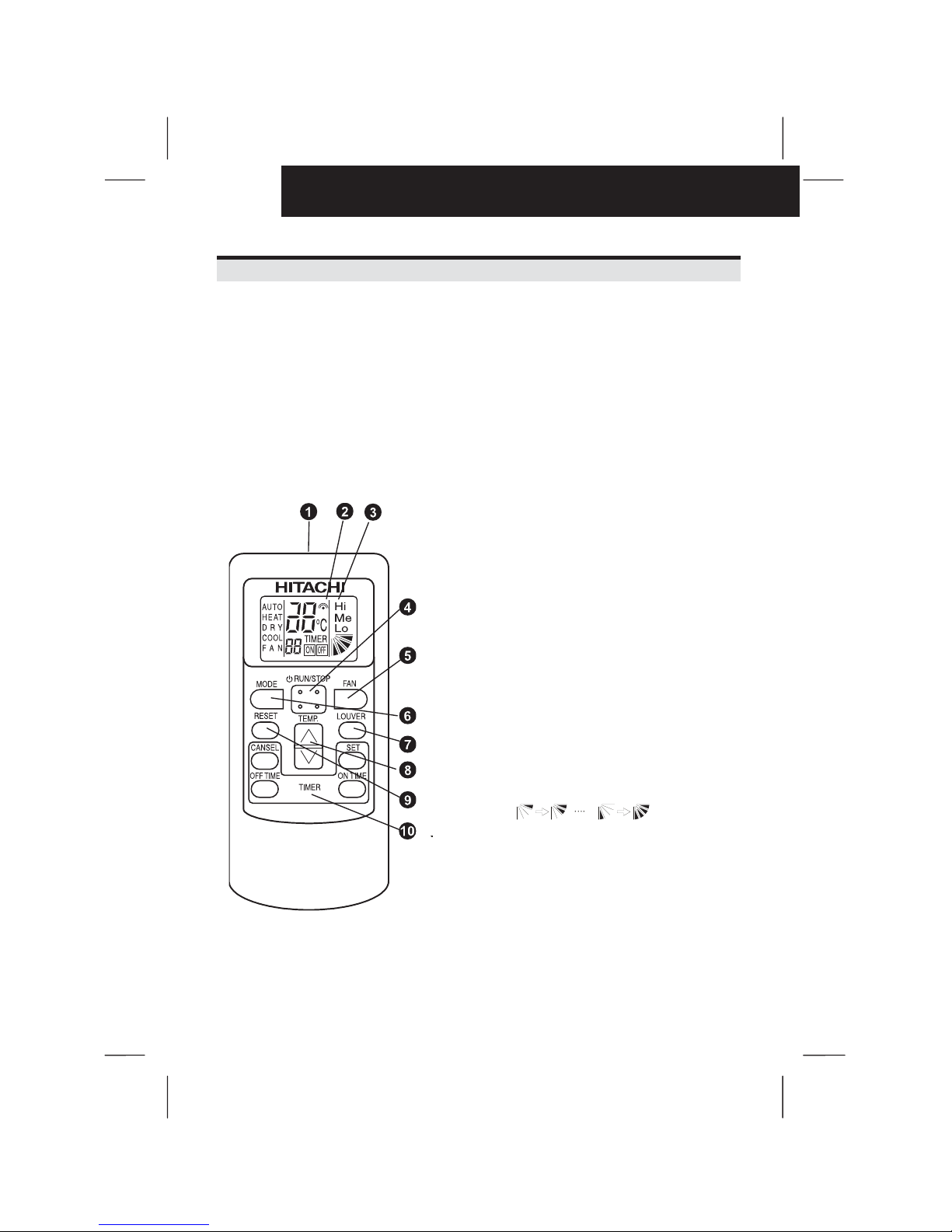
4 NAME OF PARTS
Controller
This controller is used to send commands about operation mode, timer setting, etc. to the indoor
unit. Face the transmitter of the controller toward the receiver of the indoor unit and press the
switch of required operation so that commands (by infrared rays) are sent to the indoor unit. The
distance for transmitting is approximately 6 meters as a maximum. (The capable distance for
transmitting will get shorter in case that the transmitting angle is not vertical to the receiver or an
electronic type light is used in the room, etc.).
Transmitter
Point the transmitter towards the receiver of the indoor unit when
sending commands. The Transmitting indication on the liquid crystal
display flashes when sending commands.
Transmitting Indication
Liquid Crystal Indication
The set temperature, timer operation, position of air louver,
operation mode, air flow mode, etc.. are indicated.
The diagram of the display shown on the left is for explanation
purposes only. The display will differ during actual operation.
Run/Stop Switch
Operation of the unit con be started or stopped by pressing this
switch.
Fan Speed Switch
Press this switch to select the fan speed. By repeatedly pressing the
button, the setting will change sequentially through HIGH, MED and
LOW. (Fan speed is fixed at low for dry operation).
Mode selection switch
By repeatedly pressing the mode switch, the unit cycles through the
different operating modes in the order of HEAT, DR, COOL and
FAN. To select auto operation, press the switch for more than 3
seconds. If the switch is pressed again, it will return to FAN mode.
Louver Angle Switch
The airflow angle and auto-louver operation can be set by this
switch. When pressing the switch, the angle is changed in the
following order. (In cool or dry operation modes, steps 1-5 and Auto
swing are available).
1 Step 2 SteP 7 StepAuto Swin
g
Temp. Switch
The setting temperature con be adjusted using the switch.
Reset Switch
(1) Press RESET to turn off the filter indicator lamp after filter
cleaning.
(2) If the unit is stopped abnormally due the protection devices etc...
press the RESET switch to cancel the control stoppage after the
cause of abnormality has been remove.
Timer Switches
Four switches control the timer operation.
The set time can be changed by pressing "ON TIME" or "OFF TIME"
and is set by pressing the "SET" switch. Timer operation can be
cancelled using "CANCEL".

OPERATION & INSTALLATION MANUAL FOR PC-LH3A
3
ENGLISH
5 SENDING COMMANDS FROM CONTROLLER
The operation commands are sent by
pressing the required operation switch
by facing the transmitter of the controller
toward the receiver of the indoor unit.
1 When the commands are sent, the
'
' indication on the liquid crystal
display of the controller flashes once.
2 The indication lamp (yellow) on the
receiver part of the indoor unit turns
ON for an instant when the indoor unit
receives the commands.
Ô
ATTENTION:
- In case that the indication lamp (yellow) does not turn ON although the commands are sent,
the commands are not received by the indoor unit. In such a case, send the commands again.
- The transmitter of the controller has the vertical directivity to the receiver, and the permissible
angle for transmitting is within 50º. However, the capable distance for transmitting gets half
when the transmitting angle is 50º, and also get shorter in case that an electronic type light is
used in the room.
NOTE:
The above figure shows the case of a 4-way cassette type indoor unit. The figures for other
models are different partially.
LCD (Liquid Crystal Display) Indication
When viewed from certain angles the LCD can be difficult to
read.
The viewing angle ranges from an optimal of 60º down to 30º,
as shown in the diagram on the right.
Receiver
Indication Lamp (Yellow)
turns ON for an instant
Receiver Part
Vertical Line between
transmiter and receiver.
Max. Distance for
transmitting 6m.
Within approx. 50°
(Directivity)
PC-LH3A
Transmitting
Indication
flashes once

4
OPERATION & INSTALLATION MANUAL FOR PC-LH3A
6 OPERATION
When operating the controller, face the transmitter toward the receiver of the indoor unit and
press the switch for the required operation as described in the item '4. Sending Commands from
Controller'.
Ô
ATTENTION:
In case that two indoor units are installed side by side, the commands from the controller may
be received by both indoor units. The function to identify each indoor unit not applicable.
7 INSTALLING ONTO THE WALL OR PILLAR
Ô
ATTENTION:
When the commands are sent by the controller hooked onto the wall, the receiver of the indoor
unit may not receive the commands.
1) Select the suitable place for handling and install the controller with the customer's acceptance.
Do not install the controller at the places as shown in the below.
*where children can touch
*where the air from the air conditioner is directly discharged
*where there is oil vapor and the oil is dispersed
*where the humidity is high
2) Pay attention to the following points in case that the controller is installed in a place where there is
medical equipment radiating electromagnetic waves.
a) Install the controller in a place where electromagnetic waves are not radiated directly toward
the electrical box of the indoor unit and the controller.
b) Keep a distance more than 3 meters away from the equipment radiating electromagnetic
waves, the receiver of the radio, etc. for prevention of the noise through the air.
c) In case that there is electric noise at the power source for the indoor unit, the treatment such
as providing a noise filter is required.
3) Do not install the controller in a place where generation, flowing, staying or leaking of flammable
gas is detected.
4) Install the controller in a place where there is a distance more than 30cm from the power supply
cable when installing the controller onto the wall.
5) Install the holding bracket (accessory) onto the wall by using screw (accessory) and attach the
controller to the holding bracket. Test Running by Controller

OPERATION & INSTALLATION MANUAL FOR PC-LH3A
5
ENGLISH
8 TEST RUNNING BY CONTROLLER
Ô
ATTENTION:
Test running by the controller can not be performed in case that the wired remote control
switch is used together; in case that multiple units are operated simultaneously (SET-FREE
and UTOPIA Series). In such cases, perform the test running by the wired remote control
switch.
1) Perform the test run after the installation work is completed.
a) Set the batteries for the controller.
b) Turn ON the power supply for the indoor and outdoor units.
c) '
' lamp (yellow) on the receiver of the indoor unit flashes (0.25 seconds ON 0.25 seconds
OFF), and then turns OFF. While the lamp is flashing, the unit will not operate because it is
initialising.
2) Set the test run mode by pressing 'SET' and
'OFF TIME' switch simultaneously for more
than 3 seconds. The LCD should be as
shown in the figure on the right.
Test Run Mode is
under suspension
3) Set the operation mode by pressing the
'MODE' switch.
OFF
TIMER
TIMER
OFF
COOL
COOL
Me
C
Test Run Mode is
under Operating
4) Operate the Test Run by pointing the transmitter towards the receiver of the indoor unit and press
the
’RUN/STOP' switch. When the commands are received by the indoor unit, the ' ' lamp
(yellow) of the receiver will come on briefly.
Check the commands are received well and the mode selected 3) is set correctly.
In the test run mode, the red lamp (RUN) of the receiver is turned ON and the green lamp
(TIMER) flashes (0.5 seconds ON 0.5 seconds OFF) (*2).
And then set off timer for 2 hours.
NOTE:
1. In the case that the '
' lamp (yellow) does not turn ON, the controls may not have reached
the receiver. Send the commands again.
2. (*2) In the case of RPK model, 'TIMER' lamp is turned OFF.
5) Adjust the angle of the air louver as follows.
The air louver has a mechanism for the auto-swing function.
Do not move the louver by hand forcefully.
a) Select the FAN mode by pressing the 'MODE' switch.
b) Set the louver angle by pressing the 'LOUVER' switch.
6) Stop the Test Run
a) Test Run is stopped after 2 hours automatically.
b) Test Run is stopped by pressing
'RUN/STOP' switch again.
After Test Run is finished, check that the red lamp (RUN) and the green lamp (TIMER) turn
OFF.

6
OPERATION & INSTALLATION MANUAL FOR PC-LH3A
9 SIMULTANEOUS OPERATION OF MULTIPLE INDOOR
UNITS
The multiple indoor units (Max. 16 units) can be
started and stopped simultaneously by one controller.
Perform this operation only in case that multiple
indoor units are installed in a room as shown in the
figure.
CAUTION:
Do not perform this operation in case that the
multiple indoor units are installed in different
rooms separately. It may happen that some
indoor units remain unchanged
Procedures
Ô
ATTENTION:
Turn OFF all the power source before the following procedures such as wiring, setting the
rotary switch, etc.
1) Installation of Air Panel for Wireless Control
In case of simultaneous operation of plural (up to 16) units by the wireless remote control switch,
apply the air panel for wireless control only to the unit to be operated, and apply the standard
panels (for wired control) to other units. In case of applying plural air panels for wireless control,
up to 2 air panels for wireless control can be used.
In case of applying two (2) air panels for wireless control, the setting of main and sub receiver part
is required. Refer to the receiver kit installation manual.
2) Perform wiring between indoor units by referring to the receiver installation manual.
3) Fix the connecting control cable (do not use the white cord of the 3-core cable) between indoor
units at certain points with bands not to run along the power supply cable inside of the indoor unit.
The same wiring is required outside of the indoor unit; keep a distance more than 30cm between
the control cable and the power supply cable, or ground one end of a conduit tube after inserting
the control cable in the metal conduit tube.
Indoor Unit
Control Cable
between Indoor
Units
Controller
Wireless
Controller
Wireless
Panel
Standard
Panel
Standard
Panel
Standard Panel or
Wireless Panel
Should be Standard Panel

OPERATION & INSTALLATION MANUAL FOR PC-LH3A
7
ENGLISH
4) Set the rotary switches (RSW) on the printed circuit boards in the electrical box of each indoor
unit as shown in the figure below.
No. 0
Unit
No. 1
Unit
No. 2
Unit
No. 3
Unit
No. 4
Unit
No. 5
Unit
No. 6
Unit
No. 7
Unit
Rotary
switch
Setting
No. 8
Unit
No. 9
Unit
No. 10
Unit
No. 11
Unit
No. 12
Unit
No. 13
Unit
No. 14
Unit
No. 15
Unit
Rotary
switch
Setting
Ô
ATTENTION:
In case that the setting of the rotary switch is not performed correctly, an abnormal operation
(irregular run/stop) may occur when test running or actual operation.
5) Check the Number of Indoor Units Connected
Check the number of indoor units connected when test running.
* The 7-segment indication of the receiver part shows the number of the indoor units connected
in case that the test running is performed by the controller. However, the number can not be
indicated for some models. In such a case, check the number by the wired controller
PC-P1HE.

 Loading...