


1
IMPORTANT:
READ AND UNDERSTAND THIS MANUAL BEFORE USING THIS WIRED REMOTE CONTROL SWITCH.
KEEP THIS MANUAL FOR FUTURE REFERENCE.
IMPORTANT NOTICE:
No part of this manual may be reproduced without written permission.
Signal words (DANGER, WARNING and CAUTION) are used to identify levels of hazard seriousness. Denitions of
identifying hazard levels are provided below with their respective signal words.
1. SAFETY SUMMARY
DANGER
DO NOT pour water into the remote control switch (hereafter called “controller”). This product is equipped
with electrical parts. If poured, it will cause a serious electrical shock.
: Immediate hazards which WILL result in severe personal injury or death.
: Hazards or unsafe practices which COULD result in severe personal injury or death.
: Hazards or unsafe practices which COULD result in minor personal injury or product or property
damage.
DANGER
WARNING
CAUTION
NOTE: Useful information for operation and/or maintenance.
WARNING
DO NOT perform installation work and electrical wiring connection by yourself. Contact your distributor or
dealer of HITACHI and ask them for installation work and electrical wiring by service person.
CAUTION
DO NOT install the indoor unit, outdoor unit, controller and cable at such places as;
1. Where there is oil vapor and the oil is dispersed
2. Where the hot springs are near (in a sulfuric environment)
3. Wheregeneration,owing,stayingorleakingofammablegasisdetected
4. Where the sea is near (in the salty environment)
5. An acid or alkaline environment
DO NOT install the indoor unit, outdoor unit, controller and cable within approximately 3 meters from strong
electromagnetic wave radiators such as medical equipment. In case that the controller is installed in a place
where there is electromagnetic wave direct-radiation, shield the controller and cables by covering with the
steel box and running the cable through the metal conduit tube.
Incasethatthereiselectricnoiseatthepowersourcefortheindoorunit,provideanoiselter.
2. Installation Work
[2.1 Selection of Installation Place]
1) Select a suitable place for handling and determine the installation place of the controller with the customer’s
acceptance. Do not install the controller at such places as;
where children can touch
where the air from the air conditioner is directly discharged
[2.2 Before Installation]
This packing contains the following parts.
[A] Remote Control Switch (Q’ty: 1, For Operation Control)
[B] Screw <M4x16L> (Q’ty: 2, For Fixing the Holding Bracket onto the Wall)
[C] Ring Core (Q’ty: 1)
[D] Band (Q’ty: 1, For Fixing Cable to Ring Core)
[E] Operation Manual (Q’ty: 1)
The box
is for checking work. Check the box after checking.
Installation & Maintenance Manual
Wired Remote Control Switch (Model: PC-AR)
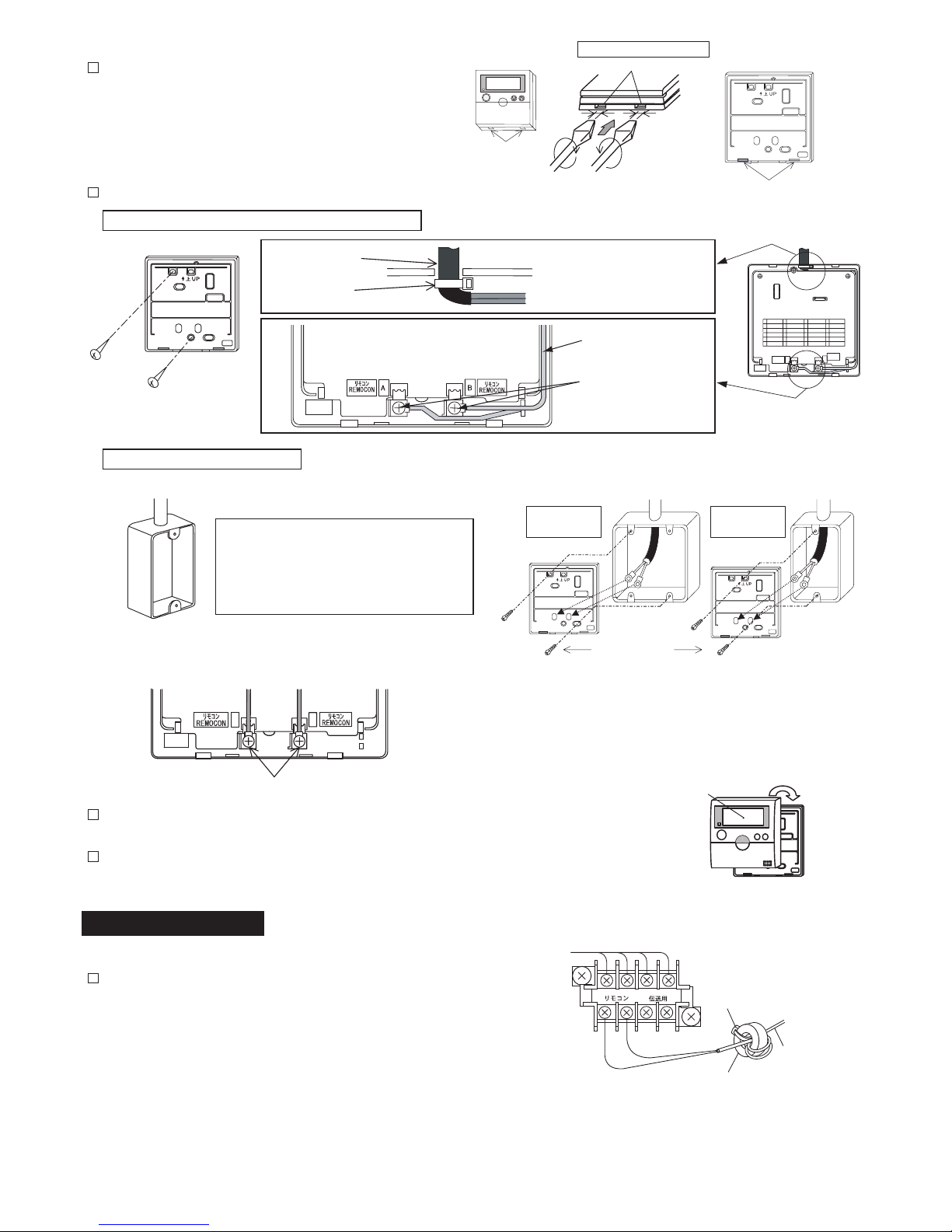
[2.3 Installation Space]
1) In case of installing the controllers in vertical line, keep a distance more than 50mm
between the controllers vertically. If the distance is insufcient, the front cover of
the controller can not be opened wide enough.
More than 50m
m
317B39060
2
A. In Case of Exposing Remote Control Cable
2) Attach the controller to the holding bracket and connect the cable as follows.
3. Peel the insulation at the end of the cable and
clamp the M3 solderless terminals (eld-supplied).
3) Attach the controller to the holding bracket. Be careful not to pinch the cable
when attaching it.
4) Remove the protection lm from the liquid crystal display.
1. Prepare eld-supplied JIS Box (JIS C 8340)
Band Stopper
(Field-Supplied)
Cable
Attach the stopper to the
cable at the inside of the
draw-out hole.
Fix the holding bracke
t
onto the wall with
screws (accessory).
B. When Using Switch Box
The following 5 types are available.
1. Switch Box for 1 controller (Without Cover)
2. Switch Box for 2 controllers (Without Cover)
3. Switch Box for 1 controller (With Cover)
4. Switch Box for 2 controllers (With Cover)
5. Outlet Box (With Cover)
2. Lead the cable through the conduit tube in the wall.
3. Electrical Wiring
JIS Box for
2 Controllers
JIS Box for
1 Controller
M4 Screws
(Field-Supplied)
Remove
the protection film.
A
B
Connect the terminals.
[2.4 Installation Procedures]
1) Insert the edge of the slotted screwdriver into the
groove at the bottom of the holding bracket, push
and turn the slotted screwdriver and then remove
the controller from the holding bracket.
Groove Part
Groove for Attaching Controller
Approx. 6mm.
Slotted Screwdriver
Figure Seen from Bottom Side
Groove Part for Removing Controller
[3.1 Standard Wiring]
1) Attach the ring core (color: black, accessory) when installing the
indoor unit as follows.
[Procedures]
Insert the control cable into the hole of ring core and wind it at
two turns as shown in the right gure before connecting it to the
terminal block. Fix the control cable with the band (accessory).
TB2
Ring Core
Band
Control Cab
le
12A B
Lead the cable with its
sheath peeled through
the groove.
Peel the insulation at
the end of the cable and
clamp the M3 solderless
terminals (field-supplied)
.

3
ATTENTION: Always make sure to turn off the power of the indoor unit when performing electrical wiring work. Performing
electrical wiring work with the power on can damage the circuit boards of the indoor unit and the controller.
Twist Pair Cable (1P-0.75mm2)
Diameter: φ7
Color: Ivory
50mm
100mm
Solderless Terminal
(X Type)
1.25-3X
● Remote Control Cable <Option>
Model: PRC-
K
The number of indicates the length (m) of the cable
(
= 5,10,15).
*for Australia
Connect the both ends of shield net of the shield tube to the
earth as shown right gure.
REMOCONAREMOCON
B
REMOCONAREMOCON
B
AA
B
B
Max. 16 Indoor Units
Controller
Controller
(Subsidiary)
Electrical Box
of Indoor Unit
Electrical Box
of Indoor Unit
M3
Screws
Terminal BoardTerminal Board
M3.5
Screws
M3.5
Screws
Twist Pair Cable with Shield Tube: 1P- 0.75mm2 or more
Remote
Control
Cable
Earth Screw
TB2
TB1
Power Source Cable
Controller
Electrical Box
Indoor Unit
[3.2 Electrical Wiring for Multiple Units]
CAUTION
A. Use a 0.3 to 0.75mm2 cable for connecting. The maximum total cable length is up 30m. If the total cable length
exceeds 30m, use a twist pair cable with shield tube(1P - 0.75mm2 or more). In that case, the maximum total cable
length is up to 500m. If using in combination with the control timer, the allowable total cable length is up to 100m.
The use of a cable other than that specied above can cause of malfunction due to the effects of noise.
B. Keep a distance more than 30cm between the transmission line (remote control cable and transmission wires) and
power source of the indoor units.
If not, the air-conditioner may not operate properly or malfunction may occur due to effect of power source noise.
C. In case of simultaneously controlling multiple indoor units, set the refrigerant cycle numbers and addresses of the
indoor units without overlapping.
D. Refer to the Technical Catalog provided with each indoor unit when performing electrical wiring work between the
controller and indoor units for setting the refrigerant cycle number and the indoor unit address.
E. No gap shall exist between the remote control cable and hole of the controller case. If there is a gap, cover the gap
with vinyl tape.
If not, malfunction may occur due to entrance of water droplets or insects.
F. In case of operating with two controllers (Main and Sub), set the main and sub controllers by selecting the appropriate
function with the controllers according to the section 5. After setting it, turn off the power supply of all the indoor unit
connected to the controllers.
4. Checking Procedures
1) Turn ON the power supply for all the indoor units.
NOTE:
Although a portion of the LCD (liquid crystal display) of the controller may light immediately after the power is turned on,
this is not a malfunction.
2) For the models with the auto-address function, wait for 3 minutes approximately. The addressing is automatically
performed. (There is a case that 5 minutes is required according to the setting condition.)
3) Set the “TEST RUN” mode by pressing the “MODE” and “CHECK” switch simultaneously for more than 3 seconds.
NOTES:
A. “TEST RUN” is displayed on the LCD.
B. The total number of the indoor units connected
is indicated on the LCD.
C. In case that the indicated number is not correct, the auto-address function is not performed correctly due to incorrect
wiring, the electric noise or etc. Turn OFF the power supply and correct the wiring after checking the following
points;
(Do not repeat turning ON and OFF within 10 seconds.)
1. Power Supply for Indoor Unit is Not Turned ON or Incorrect Wiring.
2. Incorrect Connection of Connecting Cable between Indoor Units or Incorrect Connection of Remote Control Cable
3. Incorrect Setting of Rotary Switch and Dip Switch (The setting is overlapped.) on the Indoor Units PCB
D. Check to ensure that the “TEST RUN” mode is not set.
unit
Example when 5 indoor units are connected.
4
4) Canceling “TEST RUN” Mode
1. When the unit is not operating, press the RESET switch.
2. When the unit is operating, press the RUN/STOP switch.
ATTENTION:
When “00” is indicated, the auto-address function may be performing.
Cancel the “TEST RUN” mode and set it again.
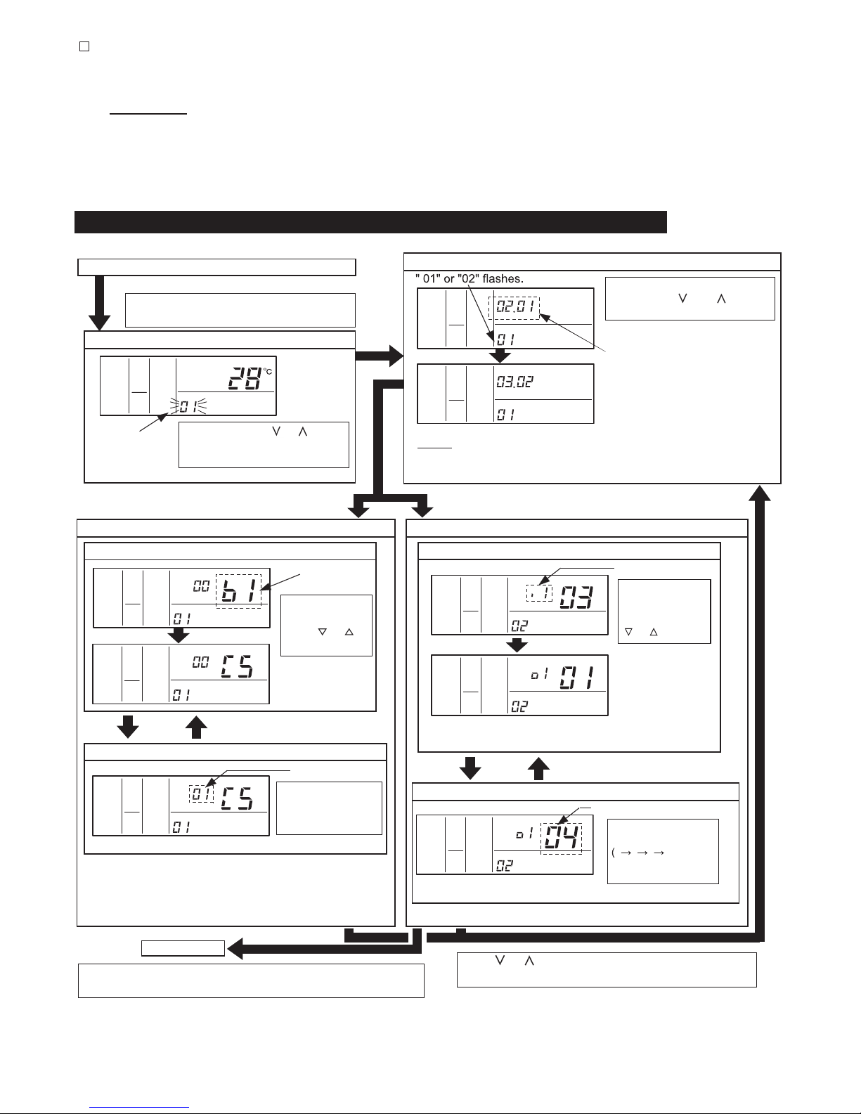
5. Optional Setting and Input / Output Setting of Indoor Unit
SERVICE
AC/
HIGH
COLO
SET TEMP.
COLO
HIGH
ADDS
RN
SERVICE
AC/
COLO
HIGH
AC/
SERVICE
ADDS RN
COLO
HIGH
AC/
SERVICE
COLO
HIGH
AC/
SERVICE
COLO
HIGH
AC/
SERVICE
COLO
HIGH
AC/
SERVICE
Normal Mode (When unit is not operating)
1. Change to the optional setting mode.
Press the "CHECK" switch and the "RESET"
switch simultaneously for more than 3 seconds.
Optional Setting Mode (Mode Number "01")
4. Selection of Optional Setting Items
Item Code of
Optional Setting
Select the item code
by pressing the
"TIME"
or
switch.
<Example>
When selecting C5
(Increasing Fan
Speed)
3. Selection of Indoor Unit for Optional Setting
Select the indoor unit to set by
pressing the " " or " " switch
and press the "CHECK" switch.
The address of the indoor unit (ADDS)
to set and the refrigerant cycle number
(RN) are indicated by 0 to 15. (The left
figure shows the No.1 cycle and No.2
indoor unit.)
<Example>
When selecting No.2 cycle and No.3 indoor
unit (The address is indicated by 0 to 15.)
NOTES: (1) In case that the both indications of the "ADDS." and "RN" show "AA",
the same setting is performed to all the indoor units.
(2) The address of indoor unit not connected is not indicated.
"SERVICE" is
indicated and the
mode number is
flashed.
Press the "TEMP." or switch
and set "01" or "02". Then press
the "CHECK" switch.
2. Selection of Optional Setting Mode
Input / Output Setting Mode (Mode Number "02")
4. Selection of Input / Output Number
Input / Output Number
Select the input /
output number by
pressing the "TIME"
or switch.
<Example>
When selecting o1
(Output 1)
In Case of Setting Other Items
In Case of Setting Other Items
COLO
HIGH
AC/
SERVICE
COLO
HIGH
AC/
SERVICE
5. Change of Setting Conditions
Setting Condition
The optional setting
condition is changed
by pressing
the "CHECK" switch.
<Example> When setting 01(Increasing Fan Speed 1)
5. Change of Setting Conditions
Contents of Input / Output Setting
<Example> When setting 04 (Output: Thermo-ON for Cooling)
The optional setting
condition is changed
...
) by
pressing the "CHECK"
switch.
Normal Mode
Press the "RESET" switch in the condition of 4 or 5 to cancel the
optional setting mode.
Press or switch in step 4 or 5 when selecting
settings for another unit.
* Refer to the contents of the setting codes for the Table A of
“Optional Setting Items”.
120
* Refer to Table B (Page 8) for contents of the input / output setting.
* Refer to the Table C for the contents of the input / output setting.

5
● Table A Optional Setting Items
6. Initialization of Optional Setting and Input / Output Setting
Normal mode (when unit is not operating)
COLO
HIGH
AC/
SERVICE
SET TEMP.
COLO
HIGH
AC/
SERVICE
ADDS RN
COLO
HIGH
AC/
SERVICE
ADDS RN
COLO
HIGH
AC/
SERVICE
ADDS RN
Press the "CHECK" switch and the "RESET"
switch simultaneously for more than 3 seconds.
1. Change to the optional setting mode.
2. Selection of Optional Setting Mode
Press the "TEMP."
"V" or "" switch,
select "07" for
the optional input
/ output setting
cancel mode, and
then press the
"CHECK" switch.
3. Selection of Indoor Unit
Select the address of the indoor unit
to be returned to the optional setting-
"07" flashes.
input/output factory settings.
Press the "TEMP." control or
switch and select the address of the
indoor unit.
NOTES:
* In case of control by using two controllers (Main and Sub),
settings shall be operated by the main controller.
* In case of selecting the address of the indoor unit not to initialize the
optional and input / output setting, "NO FUNCTION" is displayed.
* If selecting the indoor unit address "AA", the indoor units that do not
have these initialization function cannot be restore to the factory setting.
4. Optional Setting and Input/Output Setting Initialization
Press "CHECK" switch and the
initialization is performed.
It takes approximately 15 to 30
seconds.
When displayed "CL",
the optional and input
/ output settings are
initialized. (restore to
factory settings.)
In case of performing to initialize the other indoor units, repeat
the procedure from step 3.
In this case, the indoor unit address is completed to initialize,
the indication "CL" is displayed.
Normal Mode
V
V
V
"SERVICE" is indicated and the mode
number is flashed.
In case that initialization is not required, press the “RESET” switch in step 4.
Check to ensure that there are no problems
to restore the factory settings, and perform
to initialize.
Optional Setting Items
No. Items Optional Function
Individual
Setting
Setting
Condition
Contents
1b1
Removal of Heating
Temperature Compensation
due to Uneven Heat Load
00
01
02
Standard (Set Temp. +4
o
C)
Removal (Set Temp.)
Set Temp. +2
o
C (*1)
2b2
Circulator Function at
Heating Thermo-OFF
00
01
Not Available
Available
3b3
Enforced 3 Minutes
Minimum Operation Time of
Compressor
00
01
Not Available
Available
4b4 Change of Filter Cleaning Time
00
01
02
03
04
Standard
100 hours
1,200 hours
2,500 hours
No Indication
5b5 Fixing of Operation Mode
00
01
Not Available
Available
6b6 Fixing of Setting Temperature
00
01
Not Available
Available
7b7
Fixing of Operation as
Exclusive Cooling Unit
00
01
Not Available
Available
8b8 Automatic COOL/HEAT Operation
00
01
Not Available
Available
9b9 Fixing of Fan Speed
00
01
Not Available
Available
10 bA Not Prepared "- -" Fixed Not Used
11 bb
Cooling Temperature Compensation
due to Uneven Heat Load
00
01
02
Standard (No Compensation)
Set Temp. -1
o
C
Set Temp. -2
o
C
12 bC Not Prepared-
00
01
Not Used
(Use as 00 conditions)
13 bd Not Prepared-
00
01
Not Used
(Use as 00 conditions)
14 bE Not Prepared-
00
01
Not Used
(Use as 00 conditions)
X
X
X
X
X
X
The procedure for initialization of optional settings and input / output settings are as follows.

6
No. Items Optional Function
Individual
Setting
Setting
Condition
Contents
15 C1 Not Prepared-
00
01
Not Used
(Use as 00 conditions)
16 C2 Not Prepared-"- -" Fixed Not Used
17 C3 Not Prepared
00
01
Not Used
(Use as 00 conditions)
18 C4 Not Prepared
00
01
Not Used
(Use as 00 conditions)
19 C5 Hi Speed
00
01
02
Not Available
Hi Speed 1 (*2)
Hi Speed 2 (*2)
20 C6 Hi Speed at Heating Thermo-OFF
00
01
Not Available
Available
21 C7
Canceling of Enforced 3 Minutes
Minimum Operation Time of
Compressor
00
01
Available
Not Available
22 C8 Thermistor of Remote Control Switch
00
01
02
Control by Indoor Suction Thermistor
Control by Thermistor of
Remote Control Switch
Control by Average Value of
Indoor Suction Thermistor and
Thermistor of Remote Control Switch
23 C9 Not Prepared-"- -" Fixed Not Used
24 CA Not Prepared-"- -" Fixed Not Used
25 Cb Selection of Forced Stoppage Logic
00
01
Forced Stoppage Input: A Contact
Forced Stoppage Input: B Contact
26 CC Not Prepared
00
01
Not Used
(Use as 00 conditions)
27 Cd Not Prepared
00
01
Not Used
(Use as 00 conditions)
28 CE Not Prepared-
00
01
Not Used
(Use as 00 conditions)
29 CF Change of Louver Swing Angle
00
01
02
Standard (7 Steps)
Draft Prevention (5 Steps)
High Ceiling (5 Steps) (*3)
30 d1 Not Prepared
00
01
Not Used
(Use as 00 conditions)
31 d2 Not Prepared-"- -" Fixed Not Used
32 d3 Power Supply ON/OFF 2
00
01
Not Available
Available
33 d4
Prevention for Cooling Discharge Air
Temp. Decrease
00
01
Not Available
Available
34 d5
Prevention for Heating Discharge Air
Temp. Decrease
00
01
Not Available
Available
35 d6
Room Temp. Control for Energy
Saving
00
01
Not Available
Available
36 d7 Not Prepared
00
01
02
03
04
05
06
07
Not Used(Use as 00 conditions)
37 E1 Ventilation Mode
00
01
02
Automatic Ventilation
Ventilation by Total Heat Exchanger
Bypass Ventilation
(No Total Heat Exchanging)
38 E2 Increasing Supply Air Volume
00
01
Not Available
Available
39 E3 Not Prepared
00
01
Not Used
(Use as 00 conditions)
40 E4 Precooling / Preheating Period
00
01
02
Standard
30 min.
60 min.
41 E5 Not Prepared
00
01
Not Used
(Use as 00 conditions)
42 E6
Indoor Fan Operation Time After
Cooling Operation Stoppage
00
01
02
Not Available
60 min.
120 min.
X
X

7
No. Items Optional Function
Individual
Setting
Setting
Condition
Contents
43 E7 Not Prepared-
00
01
Not Used
(Use as 00 conditions)
44 E8
Fan Operation Control at Heating
Thermo-OFF
00
01
Not Available
Available
45 E9 Not Prepared-
00
01
Not Used
(Use as 00 conditions)
46 EA Not Prepared
00
01
02
Not Used
(Use as 00 conditions)
47 Eb
Fan Operation Control at Cooling
Thermo-OFF
00
01
02
Not Available
LOW
SLOW
48 EC
Forced Thermo-ON Stoppage at
Cooling
00
01
Not Available
Available
49 Ed Not Prepared
00
01
Not Used
(Use as 00 conditions)
50 EE Automatic Fan Speed Control
00
01
Not Available
Available
51 F1 Automatic OFF Timer Setting
00
01
02
23
24
0A
0B
No Function
OFF Timer by 1 hour
OFF Timer by 2 hours
OFF Timer by 23 hours
OFF Timer by 24 hours
OFF Timer by 0.5 hour
OFF Timer by 1.5 hours
52 F2 Remote Control Main-Sub Setting
00
01
Main
Sub
53 F3
Automatic Reset of Setting
Temperature (*4)
00
01
Not Available
Available
54 F4 Automatic Reset Time
00
01
02
03
30 min. (Factory-Setting)
15 min.
60 min.
90 min.
55 F5
Automatic Reset Temperature
for Cooling (*5)
19
20
25
29
30
19
o
C
20
o
C
25
o
C (Factory-Setting)
29
o
C
30
o
C
56 F6
Automatic Reset Temperature
for Heating (*6)
17
18
21
29
30
17
o
C
18
o
C
21
o
C (Factory-Setting)
29
o
C
30
o
C
57 F7
Operation Stoppage Prevention by
Remote Control Switch Operational
Error (*7)
00
01
Not Available
Available
58 F8
Lock Function for Operation Mode
Selection
00
01
Not Available
Available (Factory-Setting)
59 F9
Lock Function for Temperature
Setting
00
01
Not Available
Available (Factory-Setting)
60 FA
Lock Function for Fan Speed
Selection
00
01
Not Available
Available (Factory-Setting)
61 Fb
Lock Function for Swing Louver
Operation
00
01
Not Available
Available (Factory-Setting)
X
X
X
X
X
X
X
X
X
X
X
.
.
.
.
.
.
.
.
.
.
.
.
.
.
.
.
.
.
.
.

8
● Table B Input and Output Number Display and Connectors ● Table C Input and Output Settings and Display Codes
No. Items Optional Function
Individual
Setting
Setting
Condition
Contents
62 FC
Cooling Lower Limit for Setting
Temperature (*5)
00
01
02
09
10
Standard
Lower Limit +1
o
C
Lower Limit +2
o
C
Lower Limit +9
o
C
Lower Limit +10
o
C
63 Fd
Heating Upper Limit for Setting
Temperature (*6)
00
01
02
09
10
Standard
Upper Limit -1
o
C
Upper Limit -2
o
C
Upper Limit -9
o
C
Upper Limit -10
o
C
64
FE
Not Prepared
-
00
01
02
Not Used (Use as 00 condition)
65
FF
Lock Function for ON / OFF Timer
00
01
Not Available
Available (Factory-setting)
NOTES:
* After at least 3 minutes from the power ON, change the optional setting.
* When changing "CF" setting (change of louver swing range), restore the power supply or allow the louver to make one complete
swing fully in the auto swing mode to apply the optional setting.
* The optoinal settings are different according to the indoor and outdoor unit models. Check to ensure that the unit has the optional
setting or not.
* Record the setting conditions for each optional setting in the "Setting" column of the table.
(*1)
: The "02" setting may not be available according to the type of indoor unit.
(*2): In case of RPI models, 00: Increasing fan speed 1 (standard), 01: Increasing fan speed 2 (high static pressure)
,
02: Standard (low static pressure)
(*3): 00: Standard (7-step operation), 01: Draft Prevention (lower 2 steps cut of
f), 02: High ceiling (upper 2 steps cut off)
(*4): In case that the set temperature is changed and kept within the set time at "F4", the temperature is automatically change
d to "F5"
and "F6". (In case that the set temperature is out of range at "F5" and "F6", it is applied within upper and lower limit for the set
temperature.)
(*5)
: Applicable to fan, cooling and dry operation modes.
(*6)
: Applicable to heating operation mode.
(*7): Operation is stopped by pressing the "RUN/ST
OP" switch for 3 seconds.
X
X
X
..
..
..
..
Input and Output Number Display and Connectors
Input and Output Settings and Display Codes
Input Number Display
Port
Factory Setting
Setting
Input / Output Indication Setting Item Indication
Input1 CN3 1-2 Remote ON/OFF 1 (level)03
Input2 CN3 2-306
Output1 CN7 1-2 Operation01
Output2 CN7 1-3 Alarm02
Output3 CN8 1-2 Thermo-ON for Heating
Forbidding Remote Control
after Manual Stoppage
06
Indication Input Output
00 Not set Not set
01 Room Thermostat (for Cooling) Operation
02 Room Thermostat (for Heating) Alarm
03 Remote ON/OFF 1 (level) Cooling
04 Remote ON/OFF 2 (Operation)
Thermo-ON for
Cooling
05 Remote ON/OFF 2 (Stoppage) Heating
06
Forbidding Remote Control
after Manual Stoppage
Thermo-ON for
Heating
07
Remote Cooling / Heating
Change
Total Heat Exchanger
08 Elevating Grille Input
NOTES:
* After at least 3 minutes from the power ON, change the optional setting.
* The elevating grille input can be set to Input 2 only " " .
The elevating grille cannot be set to Input 1.
* The elevating grille output can be set to Output 1 or Output 2 only " " or " " .
The elevating grille output cannot be set to Output 3.
* Do not set the elevating grille for the total heat exchanger.
* Record the setting conditions for each input and output in the "Setting" column of the table.
Elevating Grille Output

9
7. Changing Indoor Unit Address from Controller
Normal Mode (when unit is not operating)
COLO
HIGH
AC/
SERVICE
SET TEMP.
"05" Indicates.
Press the "TEMP."
or
switch and select the address of
the indoor unit.
Select the address of the indoor
unit to be operated.
COLO
HIGH
AC/
SERVICE
ADDS RN
The address and refrigerant cycle
number of the indoor unit to be set are
displayed (the diagram at left shows the
No. 2 cycle and the No. 3 indoor unit).
Press the "TEMP" or switch,
select "05" for the address check
mode, and then press the "CHECK"
switch.
1. Change to the optional setting mode.
Press the "CHECK" switch and the "RESET"
switch simultaneously for more than 3 seconds.
2. Selection of Optional Setting Mode
"SERVICE" is
indicated and the
mode number is
flashed.
"CHECK"
Switch
3. Selection of Indoor Unit
NOTES:
* Unconnected indoor unit address is not displayed.
* In case of control by using two controllers (Main and Sub),
the indoor unit addresses cannot be checked.
4. Run and Stop Indoor Unit.
COLO
HIGH
AC/
SERVICE
ADDS RN
5. Ending Address Checking
COLO
HIGH
AC/
SET TEMP.
"RUN/STOP" switch "RESET" switch
After selecting the indoor unit, press the "RUN/
STOP" switch to operate the indoor unit of the
displayed address.
Pressing the "RUN/STOP" switch during the
indoor unit operation, returns to the indoor unit
selection procedure of step (3).
Repeat steps (3) and (4) until the address number of the indoor unit for which the address
is to be changed is able to be checked. When selecting another indoor unit, first stop the
operation of the indoor unit currently being checked.
NOTES:
* All operations other than operation of the "RUN/STOP" switch are not available during
the address checking.
* Do not operate from the central station during the address checking.
Press the "RESET" switch during the indoor
unit operation OFF to return to the normal
mode.
Once the address of the indoor unit to be
changed has been checked, change the
address of the indoor unit by proceeding to
step (3) Address Change Mode.
The address (unit number) of the indoor unit can be changed by using the controller (PC-AR).
(1) Check the Indoor Unit for which the address to be changed.
Address of Indoor Unit to be Changed is not known (check) . . . Proceed to (2) Address Check Mode.
Address of Indoor Unit to be Changed is known . . . Proceed to (3) Address Change Mode.
Initialize address set with the automatic address function or initialize address that has been changed with the
address change mode. . . Proceed to (4) Address Initialization Mode.
(2) Address Check Mode
This function is for two or more the indoor units are connected to the controller.
The indoor unit address can be checked by the indoor unit individual operation with selecting the indoor address.
NOTES:
* In case of operating with two controllers (Main and Sub), the address of the indoor units cannot be changed or
checked.
* The address may not be able to be changed depending on the type of indoor unit.
* Do not operate the central controller when in the address check mode or address change mode.

10
COLO
HIGH
AC/
SERVICE
SET TEMP.
"04" indicated.
Select the address of the indoor
unit to be changed.
COLO
HIGH
AC/
SERVICE
ADDS RN
COLO
HIGH
AC/
SERVICE
ADDS RN
The address and refrigerant cycle
number of the indoor unit to be set
change from flashing to remaining lit.
COLO
HIGH
AC/
ADDS RN
SERVICE
Press the "TEMP." or
switch to select the address of
the indoor unit and then press the
"CHECK" switch.
Press the temperature control or
switch, select "04" for the address
change mode, and then press the
"CHECK" switch.
Normal Mode (when unit is not operating)
1. Change to the optional setting mode.
Press the "CHECK" switch and the "RESET"
switch simultaneously for more than 3 seconds.
"CHECK"
switch
3. Selection of Indoor Unit
2. Selection of Optional Setting Mode
"SERVICE" is
indicated and the
mode number is
flashed.
NOTE:
* In case of selecting the address not to change, "NO FUNCTION" is
displayed.
"CHECK" switch
Select the new address to be used after
changing the address.
The refrigerant cycle number display can be
changed from 00 to 63 by pressing the "TIME"
or switch, and the unit number display can be
changed from 00 to 63 by pressing the "TEMP."
control or switch.
remaining lit when the "CHECK" switch is pressed
The address display changes from flashing to
after selecting an address.
NOTE:
A refrigerant cycle number of "99" is used in case
of temporarily avoiding setting an address when
all indoor unit refrigerant cycle numbers or unit
numbers are in use. If an address has been set
to "99", make sure to subsequently change the
address to an address within the normal address
range.
The result of changing the address is displayed several seconds after the "CHECK" switch has been pressed. "AH" is temporarily
displayed if address change processing has been completely succeeded, while "EE" is temporarily displayed if the address was unable
to be changed. If this happens, repeat the procedure for changing the address.
4. Change the address of the indoor unit.
5. Changing the address of another indoor unit.
Select the address of the indoor unit to be changed.
COLO
HIGH
AC/
SERVICE
ADDS RN
Pressing the "TEMP
." control
or switch after the result of an address change is displayed in step 4 for
changing the address of an indoor unit, returns to the selection of an indoor unit of step 3.
Repeat steps 3 and 4 until all indoor unit address changes have been completed.
6. Ending Address Change.
"AC" flashes while connections are
being checked.
Press the "RESET" switch
during selection of an indoor
unit of step 3, return to the
normal mode.
COLO
HIGH
AC/
SERVICE
ADDS RN
7. Turning ON Power of Indoor Unit.
Once turn OFF the power of the indoor unit 3 to 5 minutes after
completing step 6. After the display on the controller is no
longer displayed, turn ON the power of the indoor unit.
unit has been successfully
changed, processing for
checking connections begins.
Once the address of the indoor
NOTE:
After ending address change in step 6, make sure to turn off the
power of the indoor unit. If this procedure is not performed, the
automatic address function may not be performed properly.
NOTE:
In the case of having changed the address of the indoor unit with
the controller, make sure to record the new refrigerant cycle
number and unit number of the indoor unit that has been
changed in the entry column on the printed board.
Entry column
V
V
(3) Address Change Mode
Change the address (unit number) of the indoor unit.

11
(4) Address Initialization
This is used to initialize an address that has been changed in the address change mode or to initialize an indoor
unit address that has been set with the automatic address function. When set this function, the address of the
indoor unit is returned to the dip switch setting. (Repeat automatic address setting if the dip switch setting is to the
automatic address setting.)
Normal Mode (when unit is not operating)
SETTEMP.
SERVICE
HIGH
AC/
COLO
3. Select an indoor unit.
COLO
HIGH
AC/
SERVICE
ADDS RN
4. Address Initialization
COLO
HIGH
AC/
SERVIC
ADDS RN
The displayed address is initialized. Check that there is no problem with initializing the address.
Automatic address initialization starts when the "CHECK" switch is pressed.
Once the address has been successfully initialized, processing for checking connections starts.
If the address has already been initialized or the indoor unit does not have an address initialization
function, the address and refrigerant cycle number to be set change from flashing to remaining lit.
Repeat the setting procedure from step 3 when initializing the addresses of other indoor units.
Press the "RESET" switch to end address initialization.
Press the "TEMP." or switch
and select the address of the indoor
unit.
Press the "TEMP."
or
switch, select either "06" for the
address initialization mode, and
then press the "CHECK" switch.
1. Change to the optional setting mode.
Press the "CHECK" switch and the "RESET"
switch simultaneously for more than 3 seconds.
2. Selection of Optional Setting Mode
"SERVICE" is
indicated and the
mode number is
flashed.
"CHECK"
switch
"06" Indicates.
Select the address of the indoor unit for
which the address is to be initialized.
NOTES:
* In case of control by two controllers (Main and Sub), settings shall be
operated by the main controller.
* In case of selecting the address not to change "NO FUNCTION" is
displayed.
* When selecting indoor address "AA", the indoor unit address that does
not have an address initialization cannot be cleared.
The address and refrigerant cycle
number of the indoor unit to be set
flash temporarily.

12
8. Elevating Grille Group Setting and Cancellation
Group setting of the elevating grille refers to a function that allows all settings for the elevating grille (setting of elevating
functions for input 2 and outputs 1 and 2) to be made all at once for all indoor units connected to the controller. Settings
are made by following the procedure as follows.
NOTES:
* In case of using by two controllers (Main and Sub), the settings shall be operated by the main controller.
* Group settings are made to all indoor units connected to the controller regardless of whether or not these are actually provided with
the elevating grille. The indoor unit to be set cannot be selected. (In this case, refer to section 5, “Optional Setting and Input/Output
Setting from Controller”.)
* Please note that when functions other than the elevating grille have been set for input 2 and output 1 and 2, those settings are
cleared (namely, there are overwritten by the elevating grille function).
1. Switch to the elevating grille group setting mode.
2. Elevating grille Group Setting Procedure
"GRL" is
displayed.
Press the "RUN/STOP" switch when making group
settings. (Press the "RESET" switch to return to the
normal mode without making group settings.)
"RESET"
Switch
"RUN/STOP"
Switch
3. Display Following Elevating Grille Group Setting Procedure
"SET" flashes
for 3 seconds.
The elevating grille settings are made for all indoor units
connected to the controller. "SET" flashes for 3 seconds after
settings have been made, and then automatically returns to the
normal mode.
OLOC
HIGH
/CA
OLOC
HIGH
/CA
SET
Normal mode (when unit is not operating)
Press the “CHECK” switch and the ”RESET”
switch simultaneously for more than 3 seconds.
2. Select the input/output setting mode.
"02" Indicates.
3. Select the unit to be set.
The address and refrigerant cycle
number of the indoor unit to be
set are displayed (the diagram at
left shows the No. 1 cycle and the
No. 2 indoor unit). All units are
displayed at once when "AA" is
set for both the refrigerant cycle
number and address.
Example: Display in case of
group cancellation of all units.
4. Group cancellation procedure
Press the " "
switch.
The elevating grille settings for the selected
units are canceled all at once and input
1 and output 1 and 2 are returned to the
factory settings. "NO FUNCTION" flashes
for 2 seconds following this procedure.
"NO FUNCTION" flashes for 2
seconds
Press the "RESET" switch to cancel the
cancellation procedure.
Normal mode
OLOC
HIGH
/CA
SERVICE
SET TEMP.
OLOC
HIGH
/CA
SERVICE
ADDS RN
OLOC
HIGH
/CA
SERVICE
ADDS RN
OLOC
HIGH
/CA
SERVICE
ADDS RN
NO FUNCTION
Press the "TEMP." or switch,
select the address of the indoor
unit to be set and then press the
"CHECK" switch.
Press the "TEMP." or switch,
select "02" for the input/output
setting mode, and then press the
"CHECK" switch.
When canceling elevating grille settings for
other units, repeat selection of the indoor units
by pressing the "TEMP." or switch.
Normal mode (when unit is not operating)
1. Change to the optional setting mode.
Press the “CHECK” switch and the “RESET”
switch simultaneously for more than 3 seconds.
“SERVICE” is
indicated and the
mode number is
flashed.
317B39060(Q), 2016
© 2016 Johnson Controls-Hitachi Air Conditioning Technology (Hong Kong) Ltd.
Elevating grille settings can be cancelled all at once by following the procedures as follows.
● Elevating Grille Group Cancellation Procedure
● Elevating Grille Group Setting Procedure
 Loading...