

Hitachi PANO0162 Service Manual

DP23/23G/24
SAFETY PRECAUTIONS ......................................................................................................2
TECHNICAL CAUTIONS ......................................................................................................3
SPECIFICATIONS..................................................................................................................4
GENERAL INFORMATION ....................................................................................................5
CUSTOMIZED PICTURE AND SOUND ADJUSTMENTS....................................................6
SERVICE ADJUSTMENTS..................................................................................................17
DC VOLTAGE ......................................................................................................................36
BASIC CIRCUIT DIAGRAM ................................................................................................51
PRINTED CIRCUIT BOARDS ............................................................................................72
BLOCK DIAGRAM ..............................................................................................................74
WIRING DIAGRAM..............................................................................................................76
FINAL WIRING DRAWING ..................................................................................................78
EXPLODED VIEW ..............................................................................................................84
EXPLODED VIEW PARTS LIST ..........................................................................................90
QUICK REFERENCE PARTS LIST ....................................................................................95
REPLACEMENT PARTS LIST ............................................................................................96
DISASSEMBLY INSTRUCTIONS ......................................................................................117
TROUBLESHOOTING BLOCK DIAGRAMS......................................................................125
PA
No. 0162
NTSC
DP23/DP23G/DP24
R/C: CLU-4321UG
SPECIFICATIONS AND PARTS ARE SUBJECT TO CHANGE FOR IMPROVEMENT
JUNE 2002 HHEA-MANUFACTURING DIVISION
51UWX20B DP23
57UWX20B DP23
51GWX20B DP23G
57GWX20B DP23G
43FWX20B DP24
SERVICE MANUAL
This addendum gives differences between DP23/DP23G/DP24 and the DP27/DP27D chassis
models. For any other information, see the DP27/DP27D chassis Service Manual PA No. 0160
issued in MAY 2002.
CAUTION: Before servicing this chassis, it is important that the service technician read the
”Safety Precautions” and “Servicing Precautions” in Service Manual PA No. 0160.
PROJECTION COLOR TELEVISION
TO GO TO A CHAPTER, CLICK ON ITS HEADING BELOW

2
DP23/23G/24
Components having special safety characteristics are identified by a on the schematics and on the parts list in this service
manual and its supplements and bulletins. Before servicing this chassis, it is important that the service technician read and
follow the “Important Safety Instructions” in this Service Manual.
For continued X-Radiation protection, replace picture tube with original type or Hitachi approved equivalent type.
This Service Manual is intended for qualified service technicians; it is not meant for the casual do-it-yourselfer. Qualified
technicians have the necessary test equipment and tools, and have been trained to properly and safely repair complex
products such as those covered by this manual.
Improperly performed repairs can adversely affect the safety and reliability of the product and may void warranty. If you
are not qualified to perform the repair of this product properly and safely, you should not risk trying to do so and refer the
repair to a qualified service technician.
WARNING
Lead in solder used in this product is listed by the California Health and Welfare agency as a known reproductive toxicant which
may cause birth defects or other reproductive harm (California Health and Safety Code, Section 25249.5).
When servicing or handling circuit boards and other components which contain lead in solder, avoid unprotected skin contact
with solder. Also, when soldering do not inhale any smoke or fumes produced.
This television receiver provides display of television closed captioning in accordance with section 15.119 of the FCC rules.
FEDERAL COMMUNICATIONS COMMISSION NOTICE
This equipment has been tested and found to comply with the limits for a Class B digital device, pursuant to Part 15 of the
FCC Rules. These limits are designed to provide reasonable protection against harmful interference in a residential
installation. This equipment generates, uses, and can radiate radio frequency energy and, if not installed and used in
accordance with the instructions, may cause harmful interference to radio communications. However, there is no guarantee
that interference will not occur in a particular installation. If this equipment does cause harmful interference to radio or
television reception, which can be determined by turning the equipment off and on, the user is encouraged to try to correct
the interference by one or more of the following measures:
• Reorient or relocate the receiving antenna.
• Increase the separation between the equipment and the receiver.
• Connect the equipment into an outlet on a circuit different from that to which the receiver is connected.
• Consult the dealer or an experienced radio/television technician for help.
IMPORTANT SAFETY INSTRUCTIONS
USE ISOLATION TRANSFORMER WHEN SERVICING
!
3
DP23/23G/24
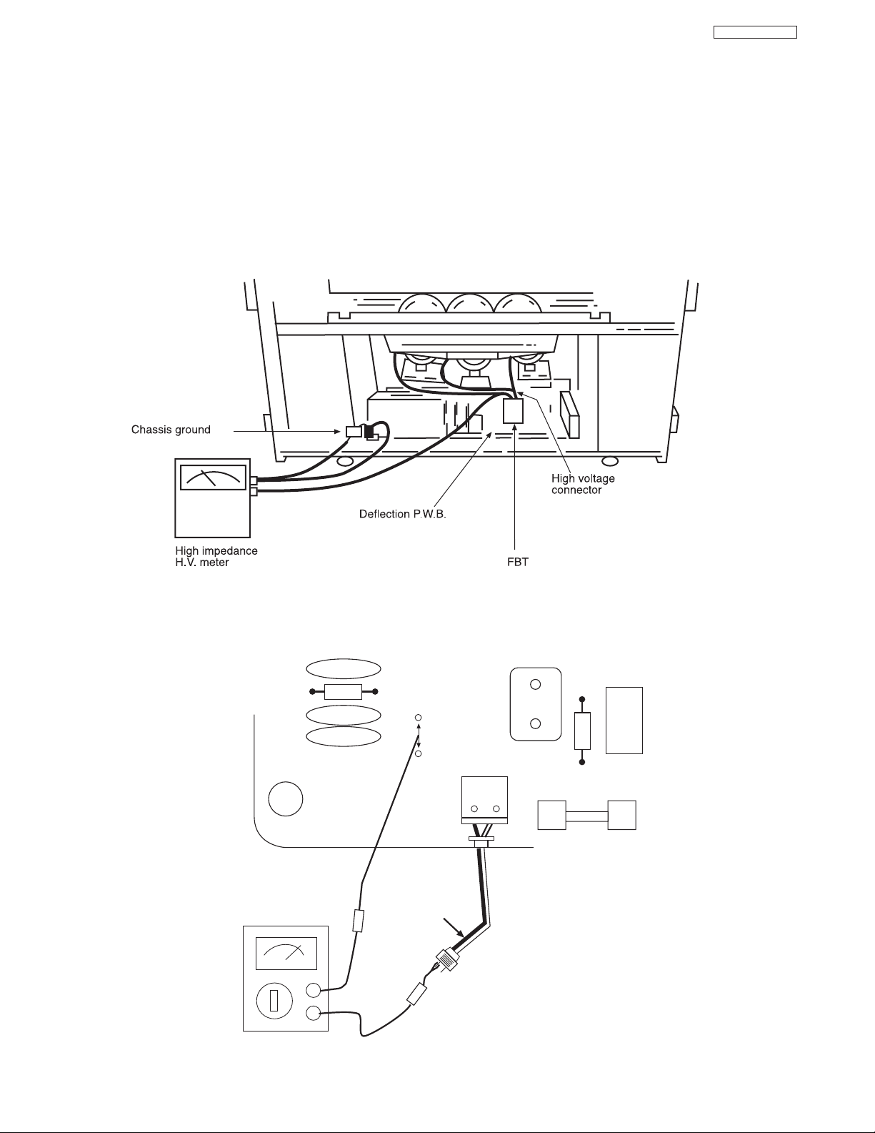
High Voltage limiter circuit operation check.
1. Turn off TV and connect jig as shown in Figure 2. Adjust
jig fully counter-clockwise for minimum resistance.
2. Set the AC input to 120V AC and turn on TV.
3. Confirm test pattern on CRT is a usable picture, then
slowly adjust jig until the picture disappears and TV shuts
down.
4. When the limiter circuit is operating properly, High
Voltage will be less than 30.5 kV at 1.4mA when TV shuts
down.
5. Turn off set immediately after checking circuit operation.
6. Unplug set for one minute to reset shutdown circuit.
Remove jig and voltmeter.
TECHNICAL CAUTIONS
(TH01)
WHITE side
GND side
TESTER
C901
R901
EF901
EF901
F901
KP01
PA
1
2
X901
R903
C981
R980
AC CORD POLARITY
This check is based on the UL standard. Use the jigs specified by the production technology section. The GND side (wider
blade) of the AC power cord should be connected to K9Y1
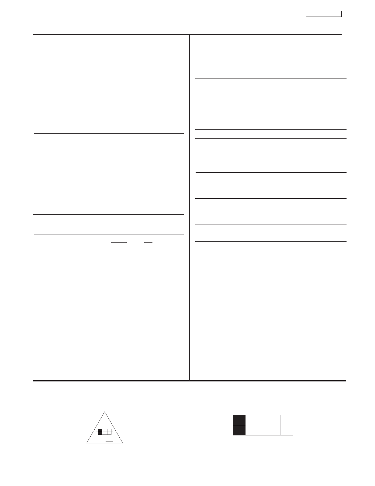
4
DP23/23G/24
Models: 51UWX20B 51GWX20B
57UWX20B 57GWX20B
43FWX20B
Cathode-Ray Tube:
51/57UWX20B R=P16LXL00RFA(U)
51/57GWX20B G=P16LXL00HHA(U)
B=P16LXL00BMB(U)
43FWX20B R=P16LXS00RFA(U)
G=P16LXS00HHA(U)
B=P16LXS00MBM(U)
Power Input: 120 volts AC, 60 Hz
Power Consumption:
• Stand-By Power
51/57UWX20 . . . . . . . . . . . . . . . . . . .0.96W
43FWX20B/51/57GWX20B . . . . . . . . .0.96W
•Power Consumption (operating)
51/57UWX20 . . . . . . . . . . . . . . . . . . .188W
43FWX20B/51/57GWX20B . . . . . . . . . .203W
•Power Consumption (maximum)
51/57UWX20 . . . . . . . . . . . . . . . . . . .227W
43FWX20B/51/57GWX20B . . . . . . . . . .248W
Antenna Impedance: 75 Ohm Unbalanced
VHF / UHF / CATV
Receiving Channel: BAND CH
VHF 2~13
UHF 14~69
EXT. Mid (A-5)~(A-1), 4+
CATV Mid. A~I
CATV Super J~W
CATV Hyper (W+1)~(W+28)
CATV Ultra (W+29)~(W+84)
Intermediate Frequency: Picture l-F Carrier 45.75 MHz
Sound l-F Carrier 41.25 MHz
Color Sub Carrier 42.17 MHz
Video Input: 1 Volt p-p, 75 Ohm
Video Output: 1 Volt p-p, 75 ohm
Audio Input: 470 mVrms, 47 k Ohm
Stereo Audio Output: 470 mVrms, 1 k Ohm
Audio Output Power:
Front: 12 watts per channel at 10% distortion,
8 ohm Impedance. Max output – 24 watts.
Anode Voltage:
DP23/DP23G/DP24
30.2±0.3kv (1.20±0.2mA)
Brightness: 51” 57” 43”
(white screen) 220cd/m
2
180cd/m
2
300cd/m
2
Speakers: 2 Woofers - 5 inch (12 cm) round
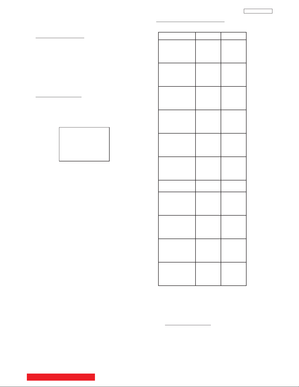
Dimension:
43” 51” 57”
Height (in.) 38 31/32 50 1/8 54 3/16
Width (in.) 41 7/32 44 1/2 54 1/64
Depth (in.) 20 5/8 25 1/32 25 1/32
Weight (Ibs.) 153 238 265
Circuit Board Assemblies:
C.P. T. (B) P.W.B. IR P.W.B.
C.P. T. (G) P.W.B. IR Sub P.W.B.
C.P. T. (R) P.W.B. Terminal P.W.B.
Power Supply P.W.B. Signal P.W.B.
Control P.W.B. Def/Convergence P.W.B.
Sensor Distribution P.W.B.
CIRCUIT PROTECTION
CAUTION: Below is an EXAMPLE only. See Replacement Parts List for details.The following symbol near the fuse
indicates fast operation fuse (to be replaced). Fuse ratings appear within the symbol.
Example:
SPECIFICATIONS
“RISK OF FIRE - REPLACE FUSE AS MARKED”
The rating of fuse F901 is 6A - 125V.
Replace with the same type fuse for continued protection
against fire.
F
6 A 125V
125V
6A
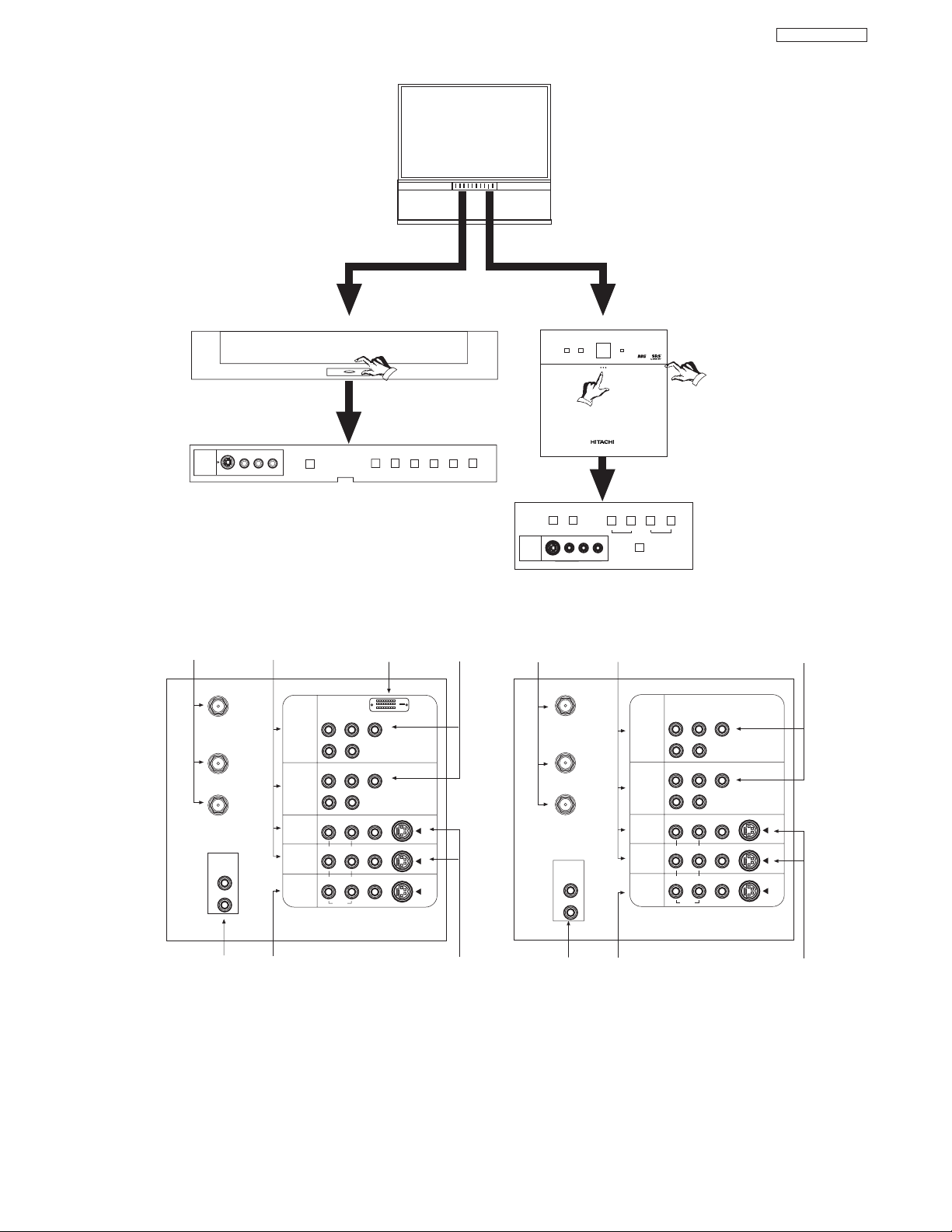
GENERAL INFORMATION
Antenna Input/Output S-VIDEO Inputs 3 and 4
Audio/Video Inputs 1, 2, 3 and 4 Component Input Y-P
BPR
MONITOR OUT DVI-HDTV Input (Input 1)
AUDIO TO HI-FI Output (UWX and GWX Models Only)
P
B
P
R
P
B
P
R
ANT A
TO
CONVERTER
ANT B
L
Y
R
(MONO)/L
AUDIO
TO HI-FI
R
S-VIDEO
S-VIDEO
S-VIDEO
Y/VIDEO
R
(MONO)/L
R
(MONO)/L VIDEO
R
(MONO)/L VIDEO
R
LVIDEO
INPUT 1
INPUT 2
INPUT 3
INPUT 4
MONITOR
OUT
AUDIO
AUDIO
AUDIO
P
B
P
R
P
B
P
R
DVI-HDTV
L
AUDIO
TO HI-FI
R
ANT A
TO
CONVERTER
ANT B
Y
R
(MONO)/L
S-VIDEO
S-VIDEO
S-VIDEO
Y/VIDEO
R
(MONO)/L
R
(MONO)/L VIDEO
R
(MONO)/L VIDEO
R
LVIDEO
INPUT 1
INPUT 2
INPUT 3
INPUT 4
MONITOR
OUT
AUDIO
AUDIO
AUDIO
INPUT 5
S-VIDEO
VIDEO
-AUDIO-
L/MONO
R
EXIT
INPUT
SELECT
MENU
MAGIC FOCUS
VOL- VOL+ CH- CH+
POWER
PULL
Models: 51GWX20B/57GWX20B/51UWX20B/57UWX20B
INPUT 3
S-VIDEO
VIDEO
AUDIO
L/MONO
R
EXIT
INPUT
SELECT
MENU
MAGIC
FOCUS
VOL- VOL+ CH-
CURSOR
POWER
PUSH
Model: 43FWX20B
CH+
FRONT CONTROL PANEL
REAR PANEL JACKS
5
DP23/23G/24

6
DP23/23G/24
REMOTE CONTROL
123
456
789
0
ANT INFO
VOL CH
POWER
TV CBL/SAT DVD/VCR
PIP
SWAP PIP MODE
FREEZE
VIDEO
PIP CH
MENU
MUTE
EXIT
LAST CH
REC
ASPECT
VIRTUAL HD
SELECT
CLU-4321UG
VID1
VID2
VID3 VID4
VID5
CLU-4321UG
7
DP23/23G/24
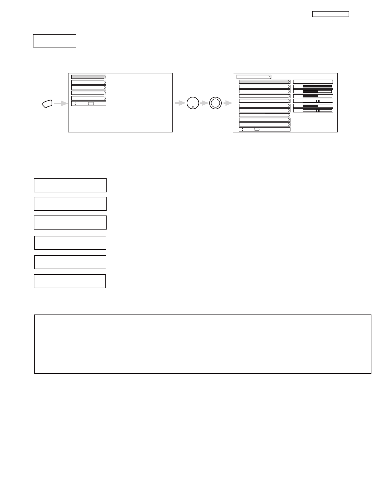
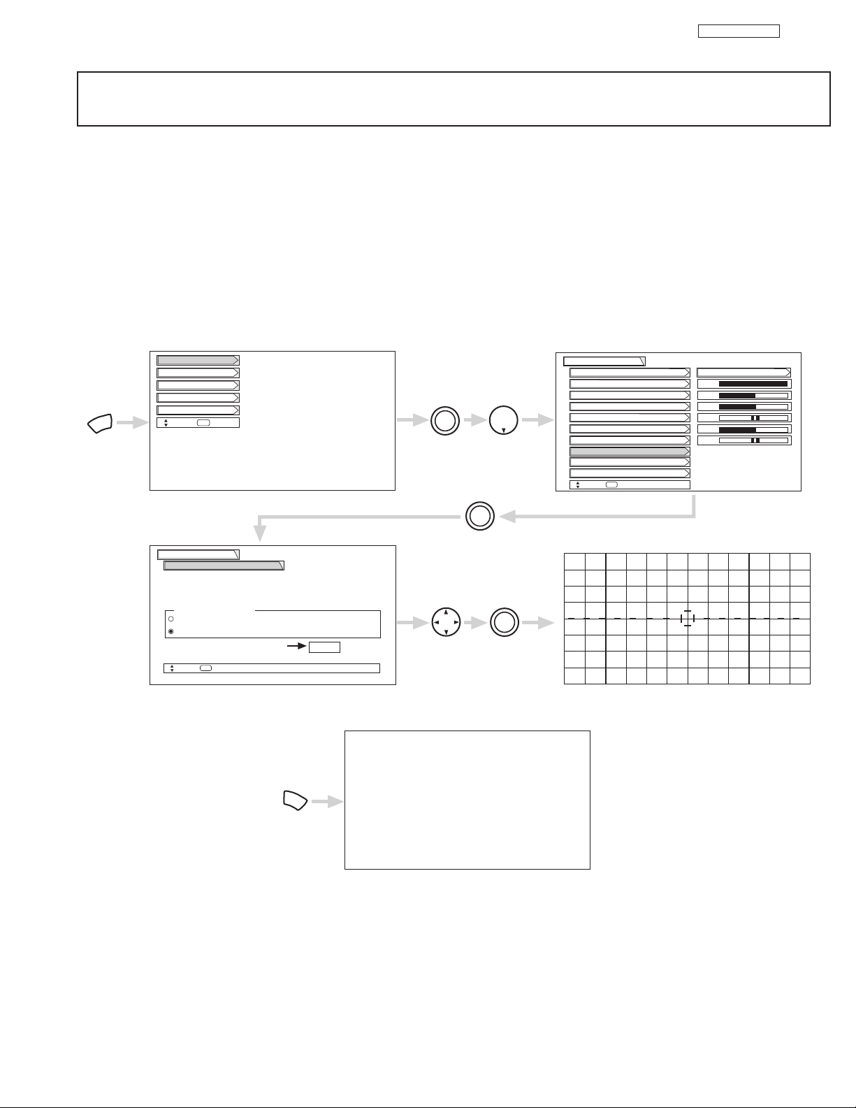
Select VIDEO to adjust picture settings and improve picture quality.
MENU
THUMB
STICK
THUMB
STICK
SELECT
Setup
Locks
Ch. Manager
Audio
Video
Move
SEL
Sel
Color
Brightness
Contrast
Picture Mode
Video
Move
SEL
Select
Vertical Position
Sharpness
Tint
Advanced Settings
Color System
100%
50%
50%
50%
0
Magic Focus
Sports
CUSTOMIZED PICTURE AND SOUND ADJUSTMENTS
Use this function to change the contrast between black and white levels in the picture. This adjustment
will only affect the picture when ADVANCED SETTINGS DIMMER is OFF.
Use the THUMB STICK or to highlight the function to be adjusted.
Press the THUMB STICK or to adjust the function. Press down on THUMB STICK to select the function settings.
Press MENU to return to main menu or select PICTURE MODE to return to previous menu.
Press EXIT to quit menu.
Use this function to adjust the level of color in the picture.
Use this function to adjust overall picture brightness.
This function allows you to select when aspect style is either 4:3 EXPANDED/ZOOM1/ZOOM2. Vertical
position can be changed with this mode. Adjustable range is -10 (video center is toward bottom of
screen) to +10 (video center is toward top of screen).
Contrast
Color
Brightness
Vertical Position
NOTES: 1. If CONTRAST is selected, you are adjusting CONTRAST. The additional menu items BRIGHTNESS, COLOR, TINT,
and SHARPNESS can be selected and adjusted in the same manner.
2. It may be necessary to adjust TINT to obtain optimum picture quality when using the COMPONENT VIDEO Y-PBP
R
input jacks.
3. If you are using the COMPONENT VIDEO input jacks (Y-PBPR) and notice that the TINT and COLOR are abnormal,
check to make sure that VIDEO- Color System is set properly.
Use this function to adjust flesh tones so they appear natural.
Tint
Use this function to adjust the amount of fine detail in the picture.
Sharpness
Video

8
DP23/23G/24
8
MAGIC
FOCUS
MAGIC FOCUS
Auto Digital Convergence Adjustment
Please turn ON your television for at least 20 minutes before using this feature.
The Magic Focus button will not work when Adjustment Mode is set to Manual (see page 9).
Your HITACHI Projection TV has three color projection tubes: one for red, one for green, one for blue. When mixed together in the proper
proportion, the output of these three color tubes can produce any color. To produce these colors, however, the beams must be precisely
aligned over each other so that the colors can be mixed. The process of aligning these picture beams is called “convergence”.
Over a period of time, the picture tubes can drift out of alignment due to normal bumps and vibrations or moving the TV. If you move
your TV, or if, after a time, you notice color rings or halos around objects in the picture, you may want to converge (align) the colors.
Properly converged, the lines appear white, which is actually a combination of the outputs of the three color tubes. The output of the
green tube is stationary. The outputs of the red and blue tubes can be adjusted. When properly aligned, the outputs of all three tubes
should be directly over each other to produce the white lines.
To simplify convergence, HITACHI incorporates a function called MAGIC FOCUS located on the front control panel, which allows the TV
to self-adjust. Press this MAGIC FOCUS button and the convergence self adjustment will start and this process will take approximately
20 seconds. If this button is pressed during this process, no change in picture quality will occur. After this 20 second self-adjust period,
picture quality will be optimum. (Do not move the TV during self-adjust.)
You may also select Magic Focus from the VIDEO menu.
Magic Focus
NOTES: Only a momentary press of the MAGIC FOCUS button is necessary to start AUTO DIGITAL CONVERGENCE. At any
time during this convergence correction process, you may press the MAGIC FOCUS button to exit the MAGIC FOCUS
mode. However, the convergence correction process needs to be completed to SAVE the new corrected convergence
data.
Magic Focus
Video
Move
SEL
Return
Aligns the Red, Green, and Blue
colors to correct for Magnetic
Influences.
Auto
Manual
MENU
THUMB
STICK
THUMB
STICK
SELECT
Setup
Locks
Ch. Manager
Audio
Video
Move
SEL
Sel
Color
Brightness
Contrast
Picture Mode
Video
Move
SEL
Select
Vertical Position
Sharpness
Tint
Advanced Settings
Color System
100%
50%
50%
50%
Magic Focus
Sports
THUMB
STICK
SELECT
Adjustment Mode
If you want to adjust now
THUMB
STICK
THUMB
STICK
SELECT
Start
MAGIC FOCUS
CUSTOMIZED PICTURE AND SOUND ADJUSTMENTS
9
DP23/23G/24
9
NOTES: 1. Please turn ON your television for at least 20 minutes before using this feature.
2. Auto Adjustment Mode is recommended. If convergence is still not acceptable, use the Manual Adjustment Mode.
DO NOT press MAGIC FOCUS or use Auto Adjustment Mode after using Manual Adjustment Mode.
Manual Convergence Adjustment Mode
Using the Remote Control, select VIDEO-MAGIC FOCUS-MANUAL ADJUSTMENT MODE-START to access convergence crosshatch
pattern. The adjustment point is indicated by the Adjustment Point Cursor.
To Move Adjustment Point
To move adjustment point, the Adjustment Cursor must be WHITE. Use the THUMB STICK to move the Adjustment Cursor. Another
way to move the Adjustment Point Cursor is to press the followiing buttons: [2] up, [4] left, [5] down, [6] right. If you use the number
buttons while the adjustment point is WHITE, it will change to RED.
To Change the Color of Adjustment Point
Press the SELECT button repeatedly (WHITE-RED-BLUE-WHITE...). Green color is fixed and cannot be adjusted.
To Adjust the Convergence
Move the Adjustment Cursor to the point to be adjusted. Use the THUMB STICK to match the RED and BLUE colors to GREEN
(reference color). Properly aligned, all three colors should appear white.
If convergence is acceptable after Manual Convergence adjustment, press EXIT button to access menu mode.
Press the [1] button on the remote control to SAVE adjusted data and return to main picture.
Press the [2] button on the remote control to CANCEL adjusted data and return to main picture.
Press the [3] button on the remote control to recall the factory pre-set convergence data.
Press the [4] button on the remote control to return to the manual convergence adjustment mode (crosshatch pattern).
Press the [9] button on the remote control to read the SAVED data.
Magic Focus
Video
Move
SEL
Return
Aligns the Red, Green, and Blue
colors to correct for Magnetic
Influences.
Auto
Manual
MENU
THUMB
STICK
THUMB
STICK
SELECT
Setup
Locks
Ch. Manager
Audio
Video
Move
SEL
Sel
Color
Brightness
Contrast
Picture Mode
Video
Move
SEL
Select
Vertical Position
Sharpness
Tint
Advanced Settings
Color System
100%
50%
50%
50%
Magic Focus
Sports
THUMB
STICK
SELECT
Adjustment Mode
If you want to adjust now
THUMB
STICK
THUMB
STICK
SELECT
Start
EXIT
DONE : [1]
CANCEL : [2]
INI. RESET : [3]
BACK : [4]
CUSTOMIZED PICTURE AND SOUND ADJUSTMENTS
10
DP23/23G/24
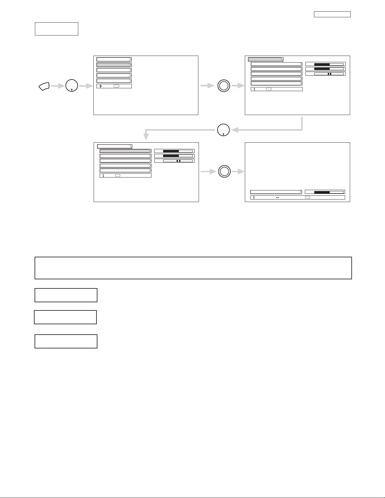
Select AUDIO to adjust the TV to your preference and to improve the sound quality.
Audio
MENU
THUMB
STICK
THUMB
STICK
SELECT
THUMB
STICK
SELECT
Setup
Locks
Ch. Manager
Audio
Video
Move
SEL
Sel
Next/Prev Change Value Return
SEL
Sound Enhancement
Balance
Bass
Treble
Audio
Move
SEL
Return
50%
50%
Sound Enhancement
Balance
Bass
Treble
Audio
Move
SEL
Select
50%
50%
Treble
50%
THUMB
STICK
Advanced Settings
Advanced Settings
LR
LR
This function controls the low frequency audio to all speakers.
Use THUMB STICK to highlight functions.
Press down on THUMB STICK to select the function setting.
Press THUMB STICK or to adjust the function.
Press EXIT to quit MENU, or select Audio to return to the main menu.
NOTE: If TREBLE is selected you are adjusting treble. The additional menu items Bass and Balance can be selected
and adjusted in the same manner.
This function controls the high frequency audio to all speakers.
This function will control the left to right balance of the TV internal speakers and the AUDIO TO HIFI output.
Bass
Balance
Treble
CUSTOMIZED PICTURE AND SOUND ADJUSTMENTS

11
DP23/23G/24
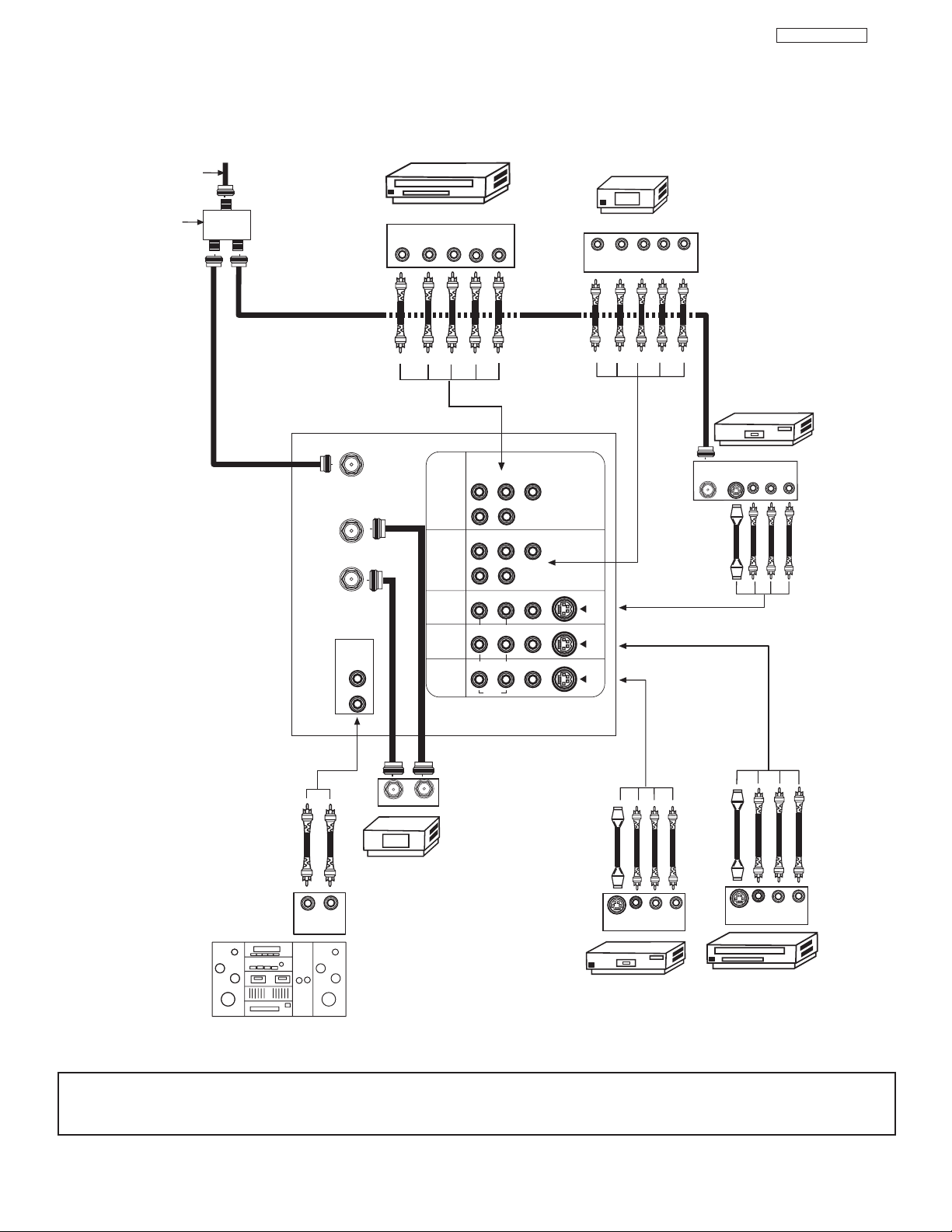
REAR PANEL CONNECTIONS
NOTE: 1.
Connect only 1 component to each input jack.
2. Follow connections that pertain to your personal entertainment system.
3. Standard video signal (Composite Video) can be input to all video inputs (Video1~Video5).
TYPICAL FULL-FEATURE SETUP
(51/57UWX20B and 51/57GWX20B MODELS)
Outside antenna or
cable TV coaxial cable
2-Way signal splitter
ANT A
TO
CONVERTER
ANT B
AUDIO
TO HI-FI
L
R
DVD Player
YP
B/CBPR/CR
OUTPUT
INPUT 1
INPUT 2
INPUT 3
INPUT 4
MONITOR
OUT
L R
P
R
R
P
R
R
R
R
R
AUDIO
DVI-HDTV
P
B
(MONO)/L
AUDIO
P
B
(MONO)/L
AUDIO
(MONO)/L VIDEO
(MONO)/L VIDEO
L VIDEO
Y
Y/VIDEO
HDTV Set-Top Box
Y P
S-VIDEO
S-VIDEO
S-VIDEO
P
B
OUTPUT
L R
R
ANT
IN
OUTPUT CAPABILITY
DIGITAL OUTPUT
VCR #1
OUTPUT
VL R
S-VIDEO
DIGITAL
LR
OUTPUT
OUTPUT
INPUT
Cable TV Box
LR
INPUT
S-VIDEO
VCR #2
V L R
INPUT
Stereo System Amplifier
V L R
S-VIDEO
OUTPUT
Laserdisc player, VCR,
camcorder, etc.
12
DP23/23G/24
REAR PANEL CONNECTIONS
NOTE: 1.
Connect only 1 component to each input jack.
2. Follow connections that pertain to your personal entertainment system.
3. Standard video signal (Composite Video) can be input to all video inputs (Video1~Video5).
Outside antenna or
TYPICAL FULL-FEATURE SETUP
(43FWX20B)
cable TV coaxial cable
2-Way signal splitter
ANT A
TO
CONVERTER
ANT B
AUDIO
TO HI-FI
L
R
DVD Player
YP
B/CBPR/CR
OUTPUT
INPUT 1
INPUT 2
INPUT 3
INPUT 4
MONITOR
OUT
L R
P
R
R
P
R
R
R
R
R
AUDIO
P
B
(MONO)/L
AUDIO
P
B
(MONO)/L
AUDIO
(MONO)/L VIDEO
(MONO)/L VIDEO
L VIDEO
Y
Y/VIDEO
HDTV Set-Top Box
Y P
S-VIDEO
S-VIDEO
S-VIDEO
P
B
OUTPUT
L R
R
VCR #1
OUTPUT
ANT
IN
S-VIDEO
VL R
OUTPUT
INPUT
Cable TV Box
LR
INPUT
S-VIDEO
VCR #2
V L R
INPUT
Stereo System Amplifier
V L R
S-VIDEO
OUTPUT
Laserdisc player, VCR,
camcorder, etc.
13
DP23/23G/24
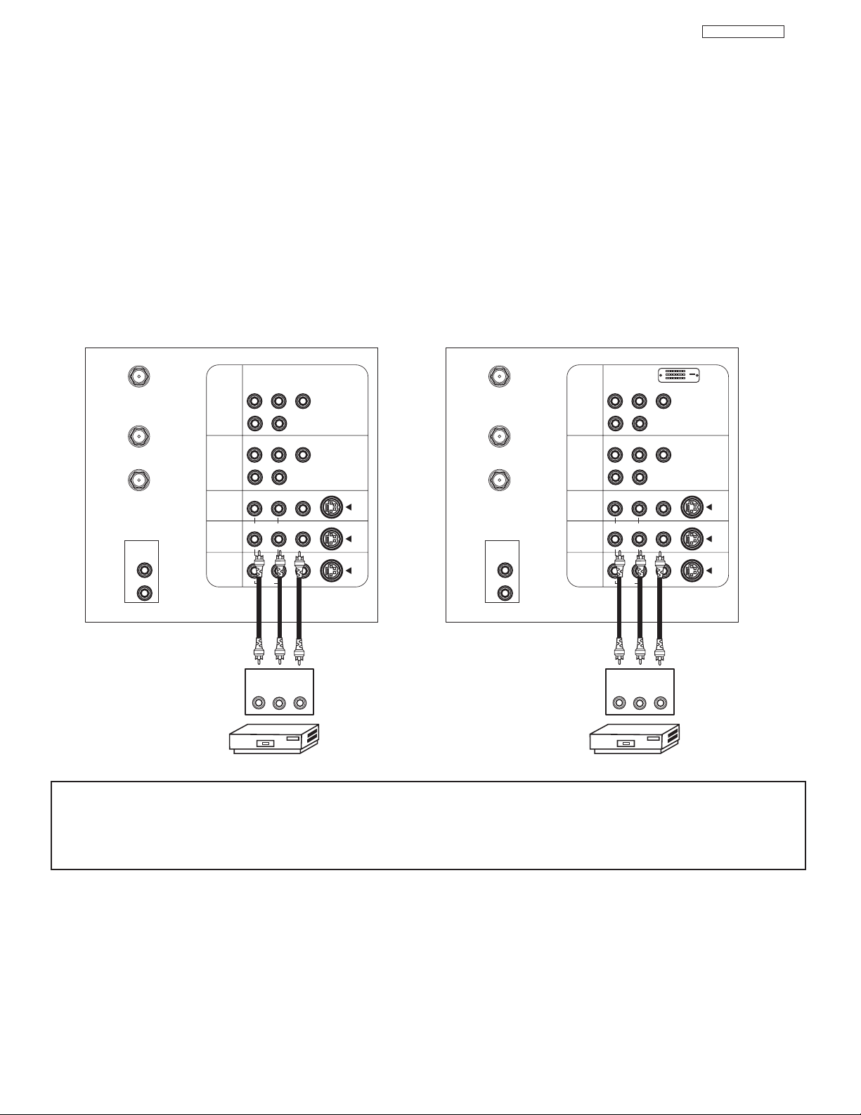
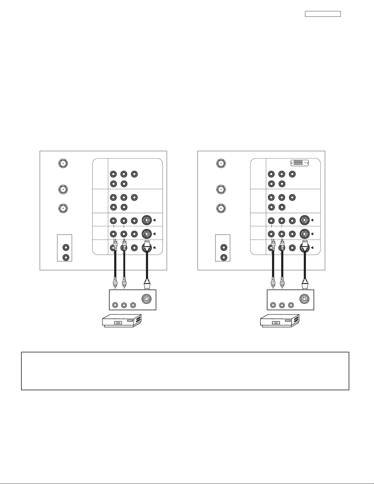
CONNECTING EXTERNAL VIDEO SOURCES
CONNECTING A STEREO SOURCE TO INPUT2~INPUT5
1. Connect the cable from the VIDEO OUT of the VCR or the laserdisc player to the INPUT (VIDEO) jack, as shown on the TV set
below.
2. Connect the cable from the AUDIO OUT R of the VCR or the laserdisc player to the INPUT (AUDIO/R) jack.
3. Connect the cable from the AUDIO OUT L of the VCR or the laserdisc player to the INPUT (AUDIO/L) jack.
4. Press the VID2~VID5 button to view the program from the VCR or laserdisc player. The VIDEO label disappears automatically
after approximately four seconds.
5. Press the ANT button to return to the previous channel.
NOTES: 1. Completely insert the connection cord plugs when connecting to rear panel jacks. The picture and sound that is
played back will be abnormal if the connection is loose.
2. A single VCR can be used for VCR #1 and VCR #2, but note that a VCR cannot record its own video or line
output. (INPUT: 3 in example on page 11 or 12) Refer to your VCR operating guide for more information on line
input-output connections.
P
B
P
R
P
B
P
R
P
B
P
R
P
B
P
R
VCR
OUTPUT
RL V
ANT A
TO
CONVERTER
ANT B
Y
R
(MONO)/L
S-VIDEO
S-VIDEO
S-VIDEO
Y/VIDEO
R
(MONO)/L
R
(MONO)/L VIDEO
R
(MONO)/L VIDEO
R
L VIDEO
INPUT 1
INPUT 2
INPUT 3
INPUT 4
MONITOR
OUT
VCR
OUTPUT
RL V
ANT A
TO
CONVERTER
ANT B
Y
R
(MONO)/L
S-VIDEO
S-VIDEO
S-VIDEO
Y/VIDEO
R
(MONO)/L
R
(MONO)/L VIDEO
R
(MONO)/L VIDEO
R
L VIDEO
INPUT 1
INPUT 2
INPUT 3
INPUT 4
MONITOR
OUT
AUDIO
AUDIO
AUDIO
L
AUDIO
TO HI-FI
R
AUDIO
AUDIO
AUDIO
L
AUDIO
TO HI-FI
R
DVI-HDTV
Models: 51/57UWX20B
51/57GWX20B
Model: 43UWX20B
14
DP23/23G/24
CONNECTING EXTERNAL VIDEO SOURCES
CONNECTING AN S-VIDEO SOURCE TO INPUT 3, 4 AND 5
1. Connect the cable from the S-VIDEO OUT of the VCR or the laserdisc player to the INPUT (S-VIDEO) jack, as shown on the TV
set below.
2. Connect the cable from the AUDIO OUT R of the VCR or the laserdisc player to the INPUT (AUDIO/R) jack.
3. Connect the cable from the AUDIO OUT L of the VCR or the laserdisc player to the INPUT (AUDIO/L) jack.
4. Press the VID3~VID5 button to view the program from the VCR or laserdisc player. The VIDEO label disappears automatically
after approximately four seconds.
5. Press the ANT button to return to the previous channel.
NOTES: 1. Completely insert the connection cord plugs when connecting to rear panel jacks. The picture and sound that is
played back will be abnormal if the connection is loose.
2. A single VCR can be used for VCR #1 and VCR #2, but note that a VCR cannot record its own video or line
output. (INPUT: 3 in example on page 11 or 12) Refer to your VCR operating guide for more information on line
input-output connections.
Model: 43FWX20B
Models: 51/57UWX20B
51/57GWX20B
ANT A
TO
CONVERTER
ANT B
AUDIO
TO HI-FI
L
R
INPUT 1
INPUT 2
INPUT 3
INPUT 4
MONITOR
OUT
P
P
B
R
(MONO)/L
R
AUDIO
P
P
B
R
(MONO)/L
R
AUDIO
(MONO)/L VIDEO
R
(MONO)/L VIDEO
R
L VIDEO
R
AUDIO
OUTPUT
RL V
VCR
Y
Y/VIDEO
S-VIDEO
S-VIDEO
S-VIDEO
S-VIDEO
ANT A
TO
CONVERTER
ANT B
AUDIO
TO HI-FI
L
R
INPUT 1
INPUT 2
INPUT 3
INPUT 4
MONITOR
OUT
DVI-HDTV
P
P
B
R
(MONO)/L
R
AUDIO
P
P
B
R
(MONO)/L
R
AUDIO
(MONO)/L VIDEO
R
(MONO)/L VIDEO
R
L VIDEO
R
AUDIO
OUTPUT
RL V
VCR
Y
Y/VIDEO
S-VIDEO
S-VIDEO
S-VIDEO
S-VIDEO
DP23/23G/24
15
15
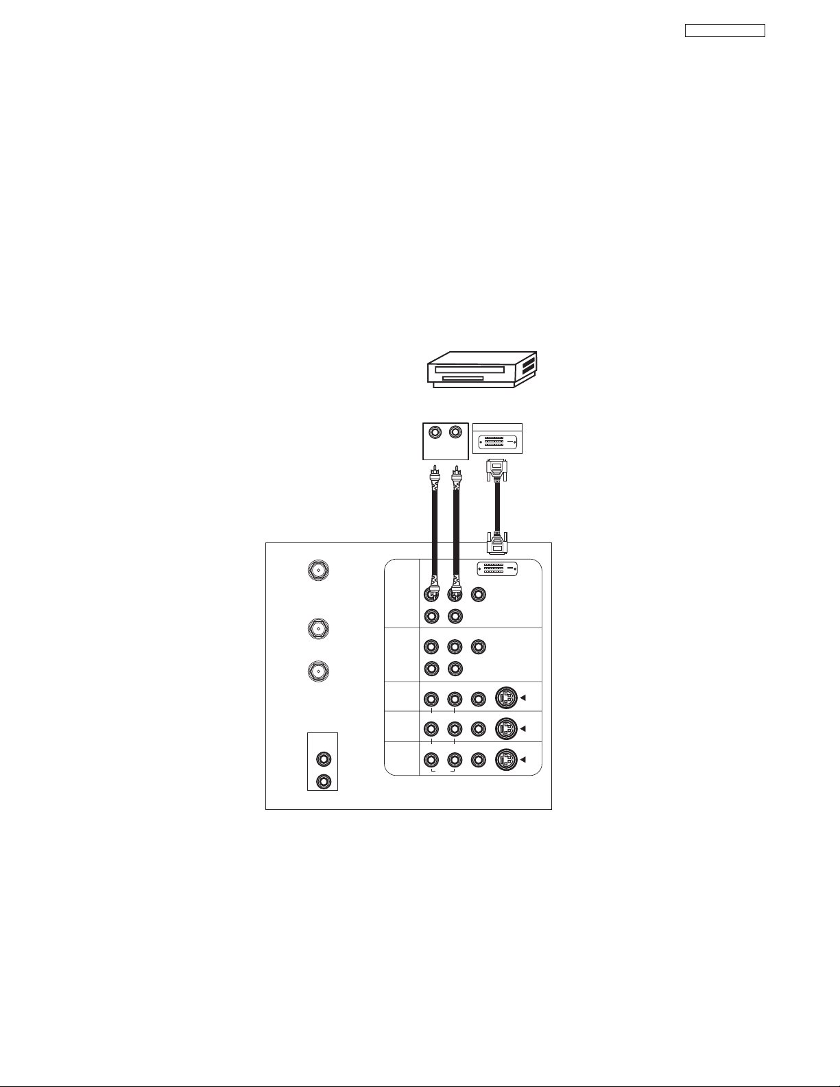
CONNECTING EXTERNAL VIDEO SOURCES
CONNECTING A COMPONENT SOURCE WITH DVI-HDTV CAPABILITY TO INPUT 1.
1. Connect the DVI connection cable from the output of the HDTV set top box or DVD player to the DVI-HDTV input as shown on
the TV set at right.
2. Connect the cable from the AUDIO OUT R of the HDTV set top box or DVD player to the INPUT (AUDIO/R) jack.
3. Connect the cable from the AUDIO OUT L of the HDTV set top box or DVD player to the INPUT (AUDIO/L) jack.
4. Press the VID1 button to view the program from theHDTV set top box or DVD player. The VIDEO label disappears automatically
after approximately four seconds.
5. Press ANT button to return to the previous channel.
P
B
P
R
P
B
P
R
DVI-HDTV
ANT A
TO
CONVERTER
ANT B
L
Y
R
(MONO)/L
AUDIO
TO HI-FI
R
S-VIDEO
S-VIDEO
S-VIDEO
Y/VIDEO
R
(MONO)/L
R
(MONO)/L VIDEO
R
(MONO)/L VIDEO
R
L VIDEO
INPUT 1
INPUT 2
INPUT 3
INPUT 4
MONITOR
OUT
DIGITAL
OUTPUT CAPABILITY
DIGITAL OUTPUT
LR
OUTPUT
AUDIO
AUDIO
AUDIO
Models: 51/57UWX20B
51/57GWX20B
16
DP23/23G/24
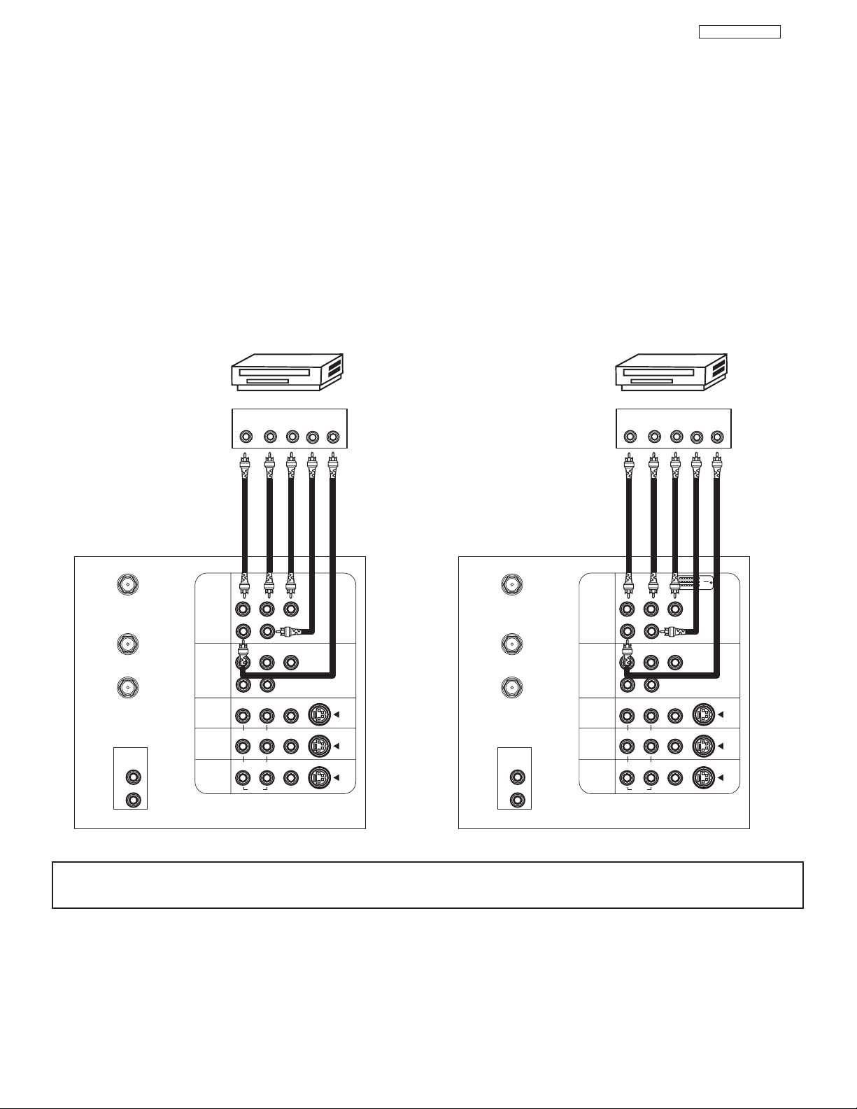
CONNECTING EXTERNAL VIDEO SOURCES
CONNECTING A COMPONENT SOURCE TO INPUT 1 OR 2: Y-PBPR.
1. Connect the cable from the Y OUT of the Laserdisc/DVD player or HDTV set top box to the INPUT (Y) jack, as shown on the TV
set at right.
2. Connect the cable from the CB/PBOUT or B-Y OUT of the Laserdisc/DVD player or HDTV set top box to the INPUT (PB)jack.
3. Connect the cable from the CR/PROUT or R-Y OUT of the Laserdisc/DVD player or HDTV set top box to the INPUT (PR) jack.
4. Connect the cable from the AUDIO OUT R of the Laserdisc/DVD player or HDTV set top box to the INPUT (AUDIO/R) jack.
5. Connect the cable from the AUDIO OUT L of the Laserdisc/DVD player or HDTV set top box to the INPUT (AUDIO/L) jack.
6. Press the VID1~VID2 button, to view the program from the Laserdisc/DVD player or HDTV set top box. The VIDEO label
disappears automatically after approximately four seconds.
7. Press the ANT button to return to the previous channel.
NOTE: Completely insert the connection cord plugs when connecting to rear panel jacks. The picture and sound that is
played back will be abnormal if the connection is loose.
P
B
P
R
P
B
P
R
P
B
P
R
P
B
P
R
DVI-HDTV
DVD Player
OUTPUT
P
RPB
Y
L R
AUDIO
AUDIO
ANT A
TO
CONVERTER
ANT B
Y
R
(MONO)/L
S-VIDEO
S-VIDEO
S-VIDEO
Y/VIDEO
R
(MONO)/L
R
(MONO)/L VIDEO
R
(MONO)/L VIDEO
R
L VIDEO
INPUT 1
INPUT 2
INPUT 3
INPUT 4
MONITOR
OUT
DVD Player
OUTPUT
P
RPB
Y
L R
AUDIO
AUDIO
ANT A
TO
CONVERTER
ANT B
Y
R
(MONO)/L
S-VIDEO
S-VIDEO
S-VIDEO
Y/VIDEO
R
(MONO)/L
R
(MONO)/L VIDEO
R
(MONO)/L VIDEO
R
L VIDEO
INPUT 1
INPUT 2
INPUT 3
INPUT 4
MONITOR
OUT
L
AUDIO
TO HI-FI
R
L
AUDIO
TO HI-FI
R
Model: 43FWX20B
Models: 51/57UWX20B
51/57GWX20B

17
DP23/23G/24
1717
1717
SERVICE ADJUSTMENTS
1. ASSEMBLED P.W.B ADJUSTMENT..................................................................................................................18
1-1. PIP Key Operation ..................................................................................................................................18
2. FINAL ASSEMBLY ADJUSTMENT (Adjustment should be according to below order) ..............................20
2-1. Cut Off Adjustment..................................................................................................................................20
2-2. DCU Phase Data Setting ......................................................................................................................20
2-3. Raster Position........................................................................................................................................20
2-4. Vertical Size ..........................................................................................................................................21
2-5. Horizontal Size ......................................................................................................................................21
2-6. Lens Focus..............................................................................................................................................21
2-7. Digital Convergence ..............................................................................................................................23
2-7-1. Magic Focus Character Set Up ....................................................................................................24
2-7-2. Magic Focus Pattern Set Up ........................................................................................................24
2-7-3. Convergence Jig Screen Specification ........................................................................................26
2-7-4. Raster Position Adjsutment ..........................................................................................................27
2-7-5. Convergence Point Adjustment ....................................................................................................27
2-7-6. Magic Focus Initialize....................................................................................................................28
2-8. Blue Defocus ..........................................................................................................................................29
2-9. White Balance ........................................................................................................................................29
2-10. Raster Distortion Check ........................................................................................................................32
3. ADJUSTMENT POINT ........................................................................................................................................34
3-1. Control PWB (DP23/DP23G) ..................................................................................................................34
Control PWB (DP24) ..............................................................................................................................35
*IMPORTANT
For many of the above adjustments, it is necessary to have an HDTV (1080i or 720P) signal generator, SDTV (480P)
signal generator, as well as the usual NTSC (480i) signal generator.
Hitachi recognizes that few companies offer HDTV or SDTV signal generators and that the cost of these
generators is sometimes prohibitive. For this reason, we suggest the use of a set-top-box for HDTV and SDTV
adjustments. Usually, there is a switch on the set-top-box which enables it to output HDTV (1080i or 720P) or
SDTV (480P) signals even with no input. In this case, the sync is automatically detected by the TV (at the Y-P
BPR
Inputs on the rear panel).
TO GO TO A SECTION, CLICK ON ITS HEADING BELOW
18
DP23/23G/24
1818
181818
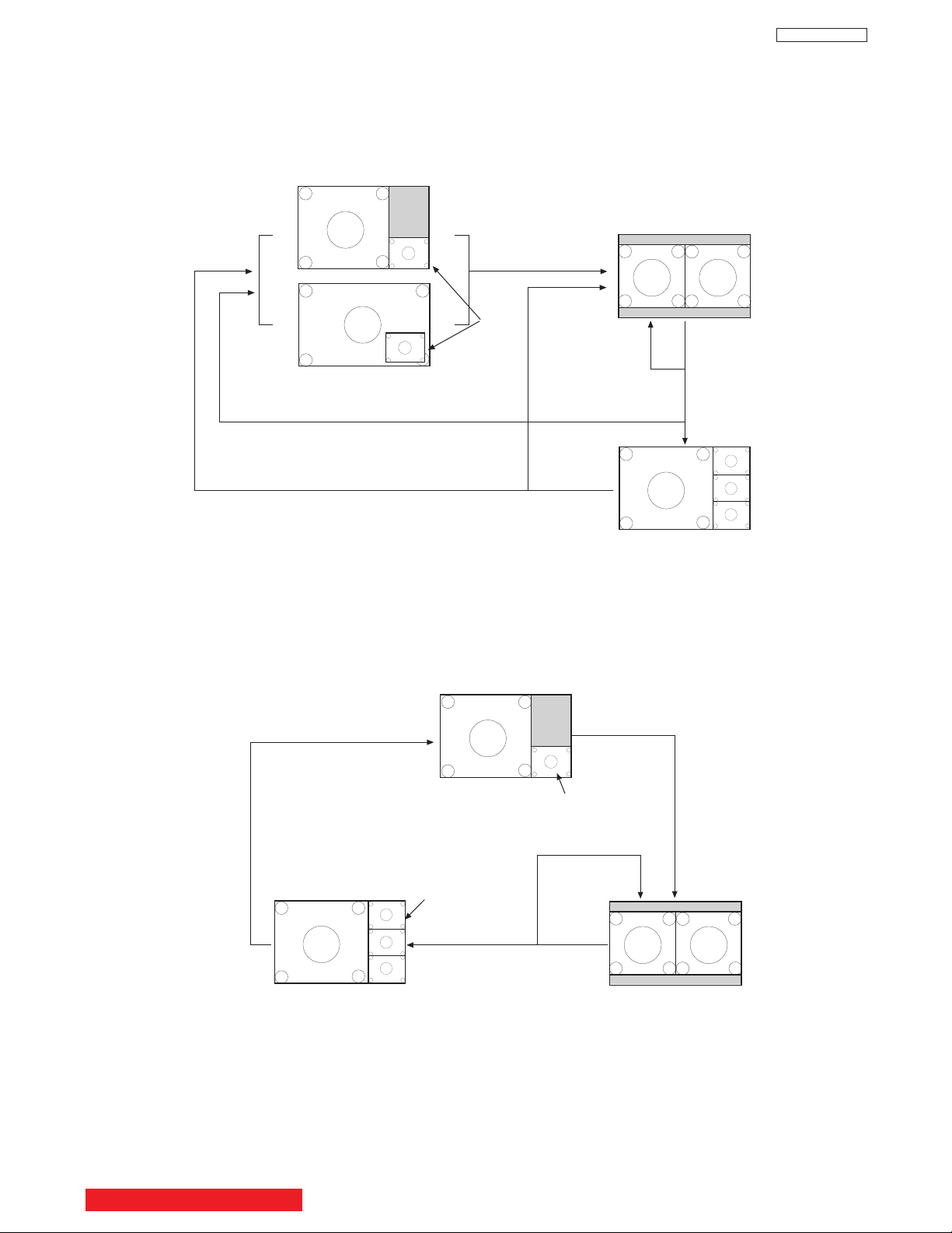
PIP Key Operation
FWX/GWX/UWX Model
Main
ANT A
SUB
SUB
SUB
Main
1080i
Main
All
Sub
All
Main
Main
NTSC
480i
PIP
Key
Main
PIP
Key
NTSC
480i
Main
Moving
SUB
SUB
SUB
Main
Moving
Sub
Frozen
Main
Main
NTSC
480i
PIP
Key
Main
PIP
Key
Sub
Frozen
Sub
Strobe
FREEZE Key Operation
FWX/GWX/UWX Model
BACK TO ADJUSTMENTS
19
DP23/23G/24
PIP Key Operation
FWX/GWX/UWX Model
PIP ON Mode
Main
ANT A
SUB
SUB
SUB
Main
All
Sub
All
Main
NTSC
480i
NTSC
480i
Main
Moving
SUB
SUB
SUB
Main
Moviing
Main
1080i
PIP Mode
key
Rating On
PIP Mode
key
PIP Mode
key
Main
Moving
Sub
Frozen
PIP Mode
key
PIP Mode
key
PIP Mode
key
Sub
Strobe
Sub
Frozen
FREEZE Key Operation
FWX/GWX/UWX Model
FREEZE Mode
BACK TO ADJUSTMENTS
2.3 Raster position adjustment
Adjustment prepar
ation
(1) The set can face east or west.
(2) Input the single cross test signal.
(3) Set video conditions to factory preset.
(4) The static focus should have been coarse
adjusted.
(5) The digital convergence RAM should be cleared
(uncorrected state). With the TV set off, press
and hold the service switch located on the
DEF./CONV. PWB and then press the power
button.
(6) Start adjustment 20 minutes or more after TV is
turned on.
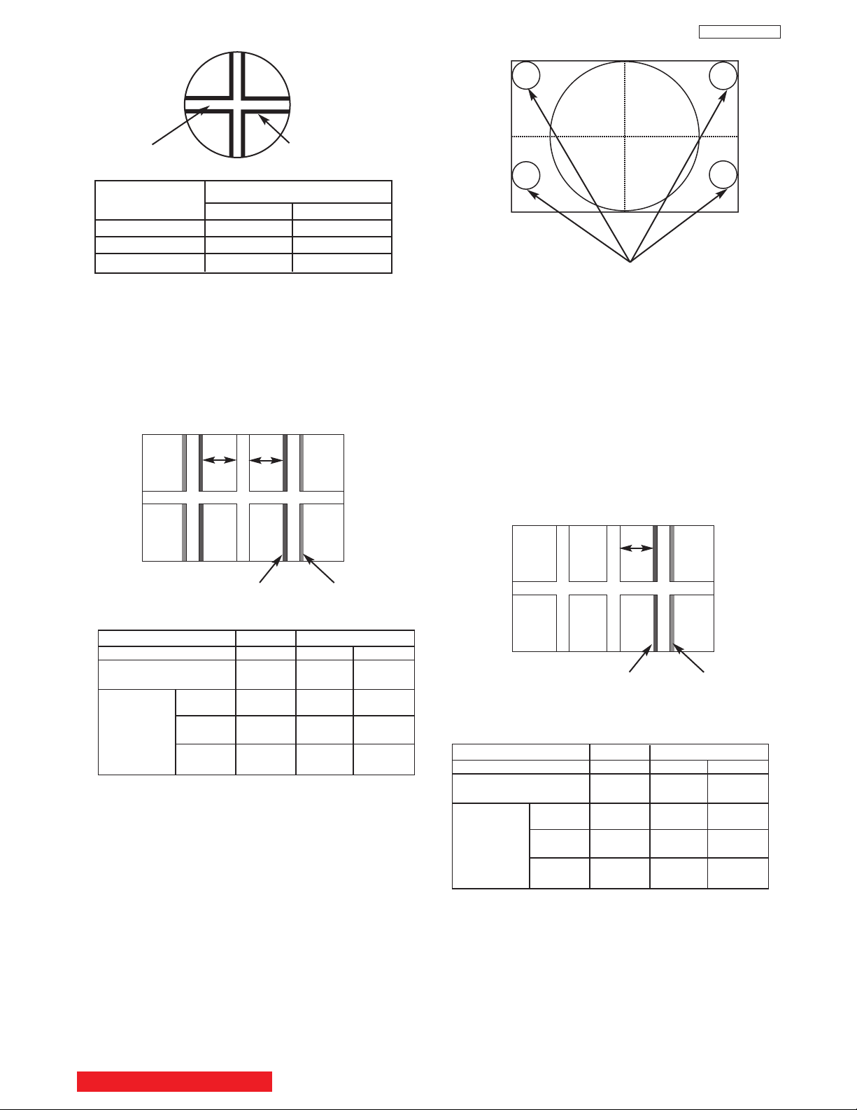
Adjustment procedure
(1) Turn the centering magnets for red, green, and
blue to satisfy the condition below. The red and
blue horizontal lines should match with green.
(RED) (BLUE)
43” 25 30
51” 20 35
57” 20 35
Tolerance: ± 2mm
1
2
Geometric
center of the
screen
R
B
(2) Upon completion of adjustment, fix centering
magnets with white paint.
NOTES: (1) If internal cross-hatch does not appear
after clearing RAM data, press service
switch again.
(2) To restore old RAM data, turn TV off and
on.
12
Units = millimeters
25.4mm = 1in.
20
DP23/23G/24
2. FINAL ASSEMBLY ADJUSTMENT
2.1 Cut Off Adjustment
Adjustment preparation
(1) Adjust screen VR’s on Focus Pack fully
counterclockwise.
(2) Adjust Focus VR’s on Focus Pack fully
clockwise.
(3) Set video conditions to factory preset.
(4) The vertical incident illumination on the screen
should be 20 lux or less (room should be dark).
Adjustment procedure
(1) Press and hold INPUT key on control panel and
then POWER ON to access I
2
C adjustment
mode.
(2) Choose “SERVICE” item from I
2
C adjustment
menu by pressing THUMB STICK .
(3) Screen VR should be turned clockwise gradually
and set so that retrace line begins to appear.
(4) Return to “NORMAL” mode by THUMB STICK
again.
(5) Adjust Focus VR’s so that focus is even all
around screen.
2.2 DCU Phase Data Setting
Adjustment preparation
(1) Cut off adjustment should be finished.
(2) Set video conditions to factory preset.
Adjustment procedure
(1) Receive any NTSC signal.
(2) Push “SERVICE ONLY” SW on DEF./CONV.
PWB. (Enter to DCU ADJ. mode).
(3) Push VID2 KEY IN [CBL/SAT] on R/C. (Green
cross hatch is displayed).
Then push EXIT key on R/C. (Character pattern
is displayed. This is the PHASE setting mode).
(4) Set PH-H phase data as shown below by using
4 and 6 key on R/C.
(5) Set PH-V phase data as shown below by using
2 and 5 key on R/C.
(6) Set CR-H phase data as shown below by using
THUMB STICK and key on R/C.
(7) Set CR-V phase data as shown below by using
THUMB STICK and key on R/C.
(8) Push VID2 KEY IN [CBL/SAT] on R/C to exit
from the PHASE mode.
(9) Push PIP MODE key 2 times on R/C to write the
phase data to memory.
(10) When Green dots are displayed, push MUTE
key to return to DCU ADJ. mode.
(11)Push “SERVICE ONLY” SW to return to RF or
VIDEO mode.
PHASE MODE
PH-H :CD
PH-V: 04
CR-H: 35
CR-V: 0A
Static Focus VR
R
GB
R
GB
Screen VR
Focus VR
Screen VR
FOCUS PACK
BACK TO ADJUSTMENTS

21
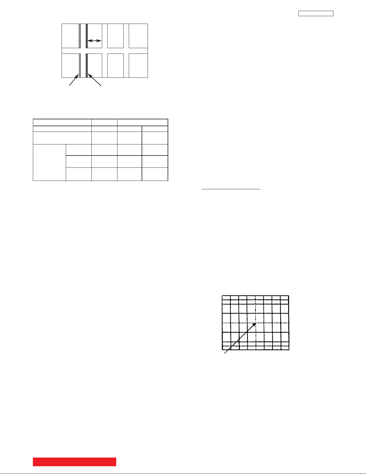
Adjustment procedure
(1) Receive any NTSC signal.
(2) Press the SERVICE ONLY SW on DEF./CONV.
PWB and POWER to display DCU uncorrected
converge data.
(3) Locate the horizontal size VR (R711 on
POWER/DEF PWB). Adjust horizontal size to
the table below.
Notes: (1) Once Normal mode Horizontal size adj. is
done. To restore old RAM data, turn TV off
and on.
(2) After adjustment, press SERVICE ONLY
switch to exit DCU crosshatch.
(3) H. SIZE adjustment is only done in
NORMAL MODE (NTSC).
=
NORMAL
MODE
43” 870
51” 1020
57” 1140
Tolerance: ± 5mm
2.5 Horizontal size adjustment
Adjustment preparation
(1) The set can face east or west.
(2) Set video conditions to factory preset.
(3) The STATIC FOCUS adjustment should have
been coarse adjusted.
(4) Convergence should not be corrected.
(5) Start adjustment 20 minutes or more after TV is
turned on.
The 6th line
from center
Between the
vertical lines
at the left and
right end.
Units = millimeters
25.4mm = 1in.
Notes:(1) If internal cross-hatch does not
appear after clearing RAM data,
press service switch again (on
DEF./CONV. PWB).
(2) To restore old RAM data, turn TV
off and on.
(3) V-Size is only done in NORMAL
mode (NTSC).
=
NORMAL
MODE
43” 460
51” 560
57” 625
Tolerance: ± 5mm
2.4 Vertical size adjustment
Adjustment preparation
(1) The set can face east or west.
(2) Set video conditions to factory preset.
(3) Convergence should not be corrected.
(4) Start adjustment 20 minutes or more after TV is
turned on.
Adjustment procedure
(1) Receive any NTSC signal.
(2) Press the SERVICE ONLY SW on DEF./CONV.
PWB and POWER to display DCU uncorrected
convergence data.
Between the
horizontal lines
at the top and
bottom
(3) Locate the vertical size VR (R607) on
DEFLECTION PWB. Adjust the vertical size
according to the following table.
The 5th line
from center
Units = millimeters
25.4mm = 1in.
21
DP23/23G/24
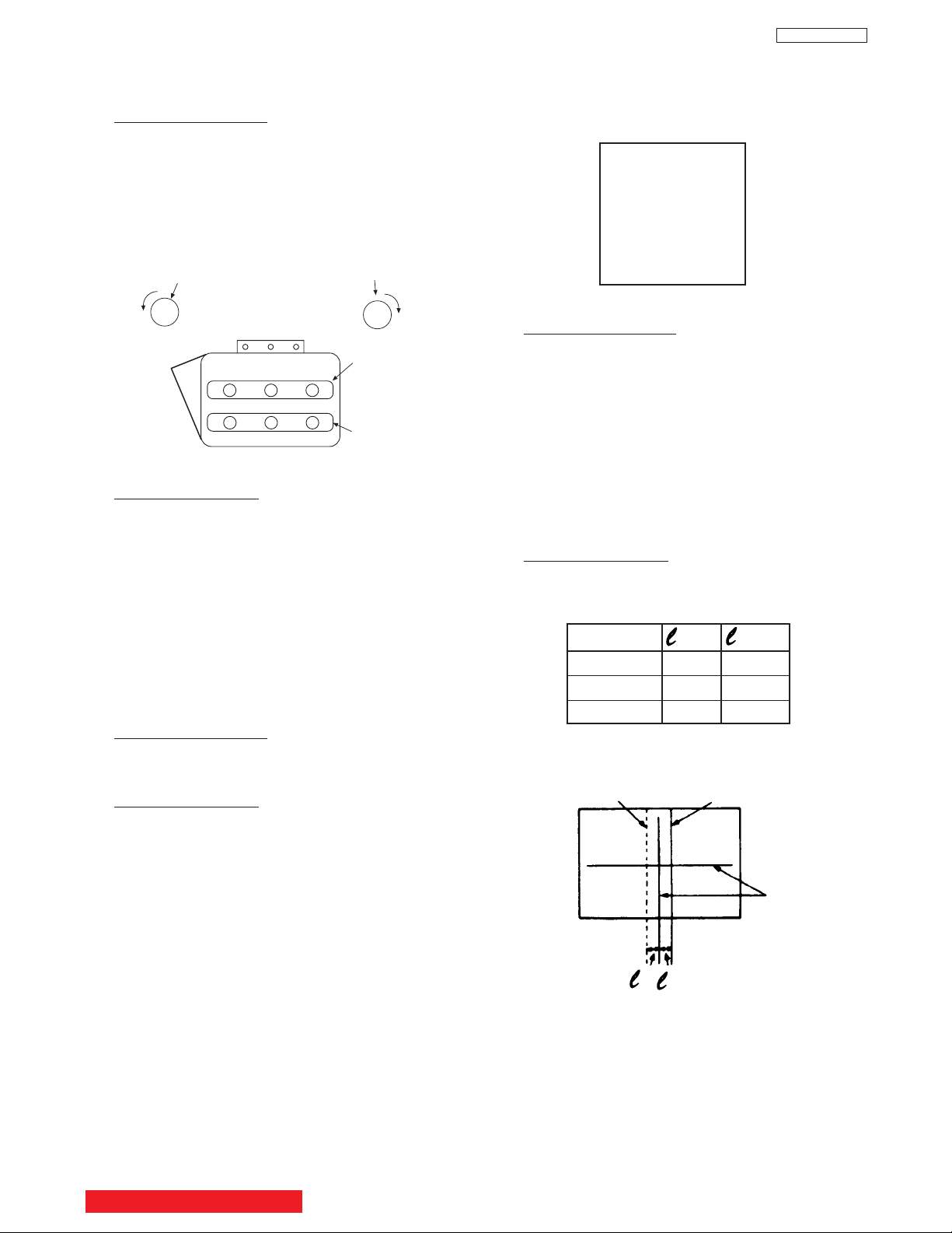
(Be careful the lens cylinder does not turn after
having tightened the screw or wing nuts. If it is
tightened too much, lens may tilt or screw may
break.)
(2) Apply covers to each color of R, G and B lenses.
And project a single color on the screen and
adjust in sequence. (The adjustment order of G,
R and B is only an example.)
(3) If the lens adjustment knob is turned clockwise
viewed from the front, the color Aberration
change as follows.
(NOTE 1)
Fixing Screw
(NOTE 2)
Fixing Wing Nut
TYPE 1 TYPE 2
Lens Assy
Lens Assy
Adjustment procedure
(1) Loosen the fixing screw or wing nut on the lens
cylinder so that the lens cylinder can be turned.
(Be careful not to loosen too much). After
completing steps (4), (5), (6) below, tighten the
fixing screws or wing nuts for each lens with a
torque of 1.18N.m (12Kgf cm) ~ 1.67N.m (17Kgf
cm).
2.6 LENS FOCUS ADJUSTMENT
Adjustment preparation
(1) The orientation of PTV set is arbitrary, west,
east, north and south.
(2) Centering DY inclination should have been
adjusted.
(3) Static focus adjustment should have been
coarse adjusted.
(4) Drive VR location adjustment should have been
completed. (Red : 12 O’clock, Green : 1~2
O’clock).
(5) Receive the cross-hatch pattern signal.
(6) Refer to setup below.
CONTRAST : HALF of full scale.
BRIGHTNESS : minimum
BACK TO ADJUSTMENTS
22
DP23/23G/24
OPTICAL FOCUSING ADJUSTMENT RED
(6) In case of B lens. Set the position where the
chromatic aberration changes from purple to
green. As shown below, observe the vertical
bright line and adjust lens focus where the
purple or green chromatic aberration slightly
appears inside and purple or green outside
(reference value : 1~3mm) at the point specified
in table below. Change the signal and fineadjust in the same way as the G lens.
O
I
L
NOTE: Setting the center between Red and crimson
is optimum.
(5) In case of R lens. Set the position where the
chromatic aberration changes from red to
crimson. As shown below, observe the vertical
bright line and adjust lens focus where the
crimson or red chromatic aberration slightly
appears inside, and crimson or red outside
(reference value : 1~3mm) at the point specified
in table below. Change the signal and fineadjust the same way as the G lens.
OPTICAL FOCUSING ADJUSTMENT GREEN
Change the signal to the circle pattern and fine
adjust. Observe the corner part of the screen,
especially observe number in the small circle
when adjusting. If the focus performance at the
screen center exceeds the lower limit, it is
acceptable.
CHASSIS DP24 DP23/DP23G
SCREEN SIZE 43” 51” 57”
L1 and L2
(PITCHES from CENTER) 3.0 1.0 1.0
BETWEEN
L1&L2 * * *
COLOR * * *
ABERRATION I 3.0mm MAX 2.0mm MAX 3.0mm MAX
****
O 3.0mm MAX 3.5mm MAX 3.0mm MAX
(NOTE) * Slightly reddish or no color
** Slightly bluish or no color
Small circle of circle pattern
NOTES: 1. Since the G light is very important for
picture quality and performance, pay
special attention in its adjustment.
2. Be careful not to touch the lens with your
fingers when adjusting.
CHASSIS DP24 DP23/DP23G
SCREEN SIZE 43” 51” 57”
L1 and L2
(PITCHES from CENTER) 3.0 3.0 3.0
BETWEEN
L1&L2 * * *
COLOR * * *
ABERRATION I 3.5mm MAX 2.0mm MAX 3.0mm MAX
** ** *
O 3.5mm MAX 2.0mm MAX 3.0mm MAX
(NOTE) * Slightly reddish or no color
** Slightly crimson or no color
Color
Aberration
Cross-Hatch
Change of Color Aberration
Short focus Long focus
RED LENS Orange Scarlet
GREEN LENS Blue Red
BLUE LENS Purple Green
O
I
L1
L2
(4) In case of G lens. Set to the point where the
chromatic aberration switches from blue to red.
If the chromatic aberration appearing all over
the screen is not the same, observe the vertical
bright line and adjust lens focus as specified in
table below. When the red chromatic aberration
appearing at both sides of the bright line is not
equal, observe the side with larger chromatic
aberration when adjusting.
BACK TO ADJUSTMENTS
23
DP23/23G/24
O
I
L
NOTE: Setting to the center between purple and
crimson is optimum.
(7) After all colors have been adjusted, display all
colors with the cross-hatch pattern signal and
check the focus performance.
(8) Then, select the circle pattern signal and check
the focus performance of each color and all
colors together.
(9) If the focus performance is not acceptable re-
adjust step (1) to (6).
OPTICAL FOCUSING ADJUSTMENT BLUE
CHASSIS DP24 DP23/DP23G
SCREEN SIZE 43” 51” 57”
L1 and L2
(PITCHES from CENTER) 3.0 3.0 3.0
BETWEEN
L1&L2 * * *
COLOR * * *
ABERRATION I 3.5mm MAX 2.0mm MAX 3.0mm MAX
****
O 3.5mm MAX 2.0mm MAX 3.0mm MAX
(NOTE) * Slightly reddish or no color
** Slightly greenish or no color
2.7 Digital convergence adjustment
Note: 1. If replacing a PRT, DY, etc. perform auto-
digital convergence first. (Press front panel
MAGIC FOCUS switch.) This can eliminate
the need for a complete digital convergence
alignment.
2. To enter digital convergence adjustment
mode without removing the front speaker
grill, please do the following:
1) Press “Magic Focus” button on the front
panel.
2) While “Magic Focus” is running, press
Magic Focus button again to “Stop”.
3) Press INFO button after “STOP” OSD
appears on the screen to enter digital
convergence mode.
4) Proceed with convergence adjustment
and save the data.
5) Do MAGIC FOCUS sensor initialization.
6) To exit, press POWER button on the front
panel.
Adjustment prepar
ation
(1) Receive an RF or video signal.
(2) Set controls to factory preset.
(3) Install jig screen on the set.
(4) Note the center of the video pattern displayed.
This is necessary to match dotted lines
(adjustment point viewed) and actual point that
is adjusted and displayed by the video signal.
(5) Press the service only switch (on DEF./CONV.
PWB). The pattern displayed is now the digital
convergence mode.
(6) When performing a complete digital
convergence adjustment CLEAR DATA in RAM.
(With the TV set off, press and hold the service
switch located on the DEF./CONV. P.W.B. and
then press the POWER button).
Adjustment Point
BACK TO ADJUSTMENTS
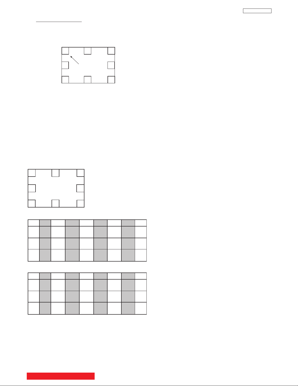
2.7.2 MAGIC FOCUS Pattern Set-Up
NOTE: (1) This instruction should be applied when a
new DCU is being replaced.
(2) This instruction shows how to set up the
pattern position for MAGIC FOCUS.
Parameter Normal Normal
ADJ. DISP 77 77
DEMO WAIT 2F 2F
INT. START 03 03
V. SQUEEZE F0 F0
INT STEP 1 02 02
INT STEP 2 06 06
INT BAR 28 25
INT DELAY 01 01
MGF STEP 1 00 00
MGF STEP 2 06 06
MGF BAR 1B 1B
MGF DELAY 01 01
SEL. STAT. 00 00
LINE WID 1F 1F
ADD LINE 09 09
SENSOR CK 00 00
PORT 0 07 07
PORT 1 06 06
PORT 2 05 05
PORT 3 04 04
PORT 4 03 03
PORT 5 02 02
PORT 6 01 01
PORT 7 00 00
AD LEVEL 03 03
CENT. BAL 00 01
E. DISPLAY 00 00
ADJ. TIMS 60 60
AD LEVEL 05 05
AD NOISE 0A 0A
PHASE MOT 60 60
H. BLK-RV 00 00
H. BLK-GV 01 01
H. BLK-BV 00 00
H. BLK-H 00 00
PON DELAY 0C 0C
IR-CODE 00 00
INITIAL 50 9E 9E
MGF 50 96 96
CENTER 50 FE FE
STAT 50 FE FE
DYNA 50 9F 9F
DP23/DP23G DP24
TABLE 1. - DCU PARAMETER
Adjustment Procedure
(1) Receive NTSC RF or video signal.
(2) With Power off, PRESS and HOLD the
SERVICE ONLY button on DEF./CONV. PWB,
then press the Power On/Off, when picture
appears release SERVICE ONLY button.
(Internal crosshatch is displayed without conv.
correction data.)
24
DP23/23G/24
2.7.1 MAGIC FOCUS Character Set-Up
This instruction should be applied when a new
DCU is being replaced.
Adjustment Prepar
ation
(1) Receive NTSC RF or video signal.
(2) With Power off, PRESS and HOLD the
SERVICE ONLY button on DEF./CONV. PWB,
then press the Power On/Off, when picture
appears release SERVICE ONLY switch.
(Internal crosshatch is displayed without conv.
correction data.)
(3) Press the SWAP button 2 times for ROM READ
operation. Picture will appear with convergence
correction data.
Adjustment Procedure
(1) Press FREEZE key on R/C. (One additional line
appears near the top and near the bottom.)
(2) Press PIPCH key, then ADJ. PARAMETER
mode is displayed as following.
(3) Press THUMBSTICK or to change the ADJ.
DISP. data.
(4) Press THUMBSTICK to access DCU
Parameter. Change the data as shown on Table
1 - DCU Parameter Data.
(5) Press PIP MODE key 2 times to write changed
data into EEPROM. (First press ADJ.
PARAMETER/ROM WRITE? is displayed for
alarm. 2nd press, writes data into EEPROM.
Green dots appear after completion of
operation.)
(6) Press MUTE key 3 times to exit from ADJ.
PARAMETER mode.
ADJ. PARAMETER
ADJ. DISP.: 77
DEMO WAIT: 2F
INT. START: 03
V. SQUEEZE: F0
BACK TO ADJUSTMENTS
25
DP23/23G/24
(7) Press PIP MODE key 2 times to write the changed
data in EEPROM. (First press, ADJ. PATTERN/ROM
WRITE ? 2nd press, writes data into EEPROM.
Green dots appear after completion of operation.)
(8) Press MUTE key to exit from PATTERN mode.
Adjustment Procedure
(1) Press FREEZE key on R/C. (One addtional line
appears near the top and near the bottom.)
(2) Press VID2 key in [CBL/SAT] on R/C, then MAGIC
FOCUS PATTERN mode is displayed as follows:
(3) Use [6] key on remote control to rotate the arrow.
Arrow indicates each sensor position. (Upper left
corner, middle top, upper right corner, right middle, in
this order).
(4) Use the keys to switch color of pattern.
INFO : Green pattern
0 : Red pattern
ANT : Blue pattern
(5) Press THUMBSTICK or to change the data
value to the horizontal direction. Press
THUMBSTICK or to change the data value to
the vertical direction.
(6) Set the data as shown below:
RH : 0A
RV : FF
1
2
3
4
5
6
7
0
1
3
5
7
0123 4567
RH 04 02 FC FE FC 02 02 02
RV 03 00 07 01 FB 01 FE 01
GH 04 00 FE 00 FE 00 02 02
GV 04 00 06 01 FC 01 FE 01
BH 06 FE FC 00 FE FE 04 02
BV 06 00 04 01 FE 01 FB 01
Pattern Position
Normal Mode (DP23/DP23G)
0
2
4
6
0123 4567
RH 04 02 FE 00 FE 02 04 02
RV 03 01 06 01 FC 01 FF 01
GH 04 00 FE 00 FE 00 02 02
GV 04 01 05 01 FD 01 FD 01
BH 04 FE FE 02 00 FE 04 02
BV 06 01 04 01 FF 01 FD 01
Normal Mode (DP24)
BACK TO ADJUSTMENTS
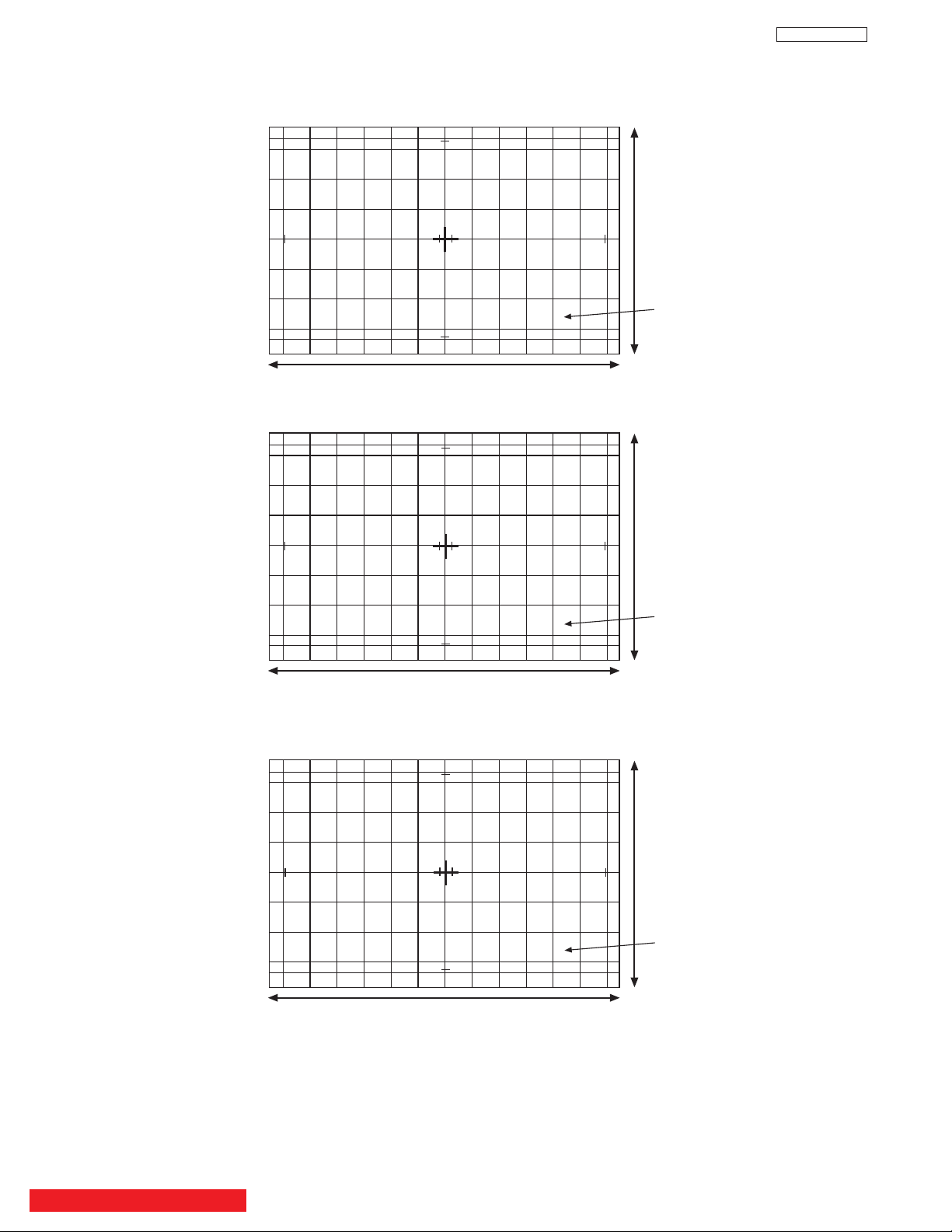
26
DP23/23G/24
19.7 90.8 90.8 90.8 90.8 90.8 90.8 90.8 90.8 90.8 90.8 90.8 90.8 19.7
30.5
41.0
30.5
41.0
82.0
82.0
82.0
82.0
82.0
82.0
1129
635
51UWX20B/51GWX20B (Part Number H312272)
51” DP2X Jig Screen
22 101.5 101.5 101.5 101.5 101.5 101.5 101.5 101.5 101.5 101.5 101.5 101.5 22
34.1
45.8
91.7
91.7
1262
710
57UWX20B/57GWX20B (Part Number H312273)
57” DP2X Jig Screen
91.7
91.7
91.7
91.7
45.8
34.1
17.0 76.5 76.5 76.5 76.5 76.5 76.5 76.5 76.5 76.5 76.5 76.5 76.5 17.0
25.7
34.5
25.7
34.5
69.1
69.1
69.1
69.1
69.1
69.1
952
535
43FWX20B (Part Number H312271)
RB
H312271
RB
H312272
RB
H312273
57”
Wide
51”
Wide
43”
Wide
2.7.3 Convergence Jig Screen Specifications
BACK TO ADJUSTMENTS

27
DP23/23G/24
Note: If only minor adjustments to convergence are
needed, the jig screen is not necessary. Use
digital data stored in memory and one color as a
reference (red, green, or blue). DO NOT CLEAR
DATA and WRITE to ROM memory.
2.7.4 Raster position adjustment
Adjustment preparation
(1) Position adjustment - This will move an entire
color. Use this adjustment to match colors at the
center of the screen. (Active video center from
external signal and physical screen center
should now match from phase adjustment).
(2) Use the buttons below to switch color to adjust.
“INFO” - Green
“0” - Red
“ANT” - Blue
Adjustment procedure
(1) Press the FREEZE button. Extra horizontal lines
appear to confirm raster position mode.
(2) Use the thumb stick to adjust position.
(3) Press FREEZE again to exit raster position
mode.
Notes: (1) Other functions cannot be accessed when
in raster position adjustment mode. Press
FREEZE and confirm extra horizontal lines
disappear to exit raster position mode.
(2) Press MENU to remove colors displayed.
2.7.5 Convergence point adjustment
Adjustment prepar
ation
(1) Select color to adjust.
“INFO” - Green
“0” - Red
“ANT” - Blue
(2) Use 4, 6, 2, and 5 to move the cursor position
(dotted lines).
(3) Use thumb stick to move the convergence point.
(4) Three adjustment modes are available:
1. (3x3) Press “INFO” 5 times (only works
when DCU is in uncorrected state)
2. (7x5) Press “0” 5 times
3. (13x9) Press “ANT” 5 times
For touch-up, only the (13x9) mode is necessary.
This will adjust every cross-hatch intersection point
on the screen.
For complete adjustment, start with (3x3) mode. This
will adjust center point and eight edge points only,
but will greatly reduce adjustment time. Then use
(7x5) mode, and finally (13x9) mode to finish
convergence.
If “S” distortion appears between cross-hatch
lines repeat (7x5) mode to change calculation
process while adjusting to remove distortion,
then return to (13x9) mode to finish touch-up
convergence.
Adjustment procedure
(1) Receive any NTSC signal.
(2) Start adjustment at the center of the screen.
(3) Continue adjustment at next closest position.
(4) Adjust center area first, ending with edge sections.
(5) Press INFO button to perform calculation operation.
This process will take about 1 second and no picture
will be seen at this time.
(6) After interpolation, check convergence again and
repeat (1)-(5) if necessary.
(7) When convergence is acceptable, press PIP MODE
to write data to ROM memory. ROM WRITE? is
displayed to alarm system that ROM will be
overwritten with new data. Press the PIP MODE
button again to write displayed data to ROM.
(8) DATA WRITE TO ROM will take approximately 4
seconds and no picture will be displayed.
(9) Green dots will be displayed when operation is
completed.
(10) Press MUTE to return to convergence pattern, then
confirm again convergence is acceptable.
(11) Press PIP MODE (ROM WRITE) mode, then press
PIP CH to initialize sensor data positions.
Notes: (1) Display only green for easier adjustment and
match to jig screen. Press “MENU”, THEN
PRESS “INFO”.
(2) Perform interpolation and data write to ROM
after green adjustment. Once green has been
confirmed to match jig screen, the jig screen can
be removed. Do not readjust the green color
after jig screen has been removed. This is now
your reference color.
(3) Display green and red only and match red to
green.
(4) Display all colors and match blue to green and
red. Touch-up red color if necessary.
(5) Existing DATA in ROM can be read by pressing
the SWAP button 2 times. This data can be used
after replacing a component (CRT, DY, etc.)
Where complete convergence adjustment is not
necessary, be careful not to overwrite this data.
DO NOT write cleared RAM data into ROM or a
complete convergence adjustment will be
necessary. Remember to try MAGIC FOCUS
before starting convergence adjustment to
minimize adjustment time.
(6) To confirm and fine tune the convergence at the
edge of the screen, press the PIP CH button on
the remote control while in the digital
convergence adjustment mode (DCAM) for
additional lines at the edge of the screen. Fine
tune the edge convergence as necessary. To
exit, press PIP CH again.
BACK TO ADJUSTMENTS
28
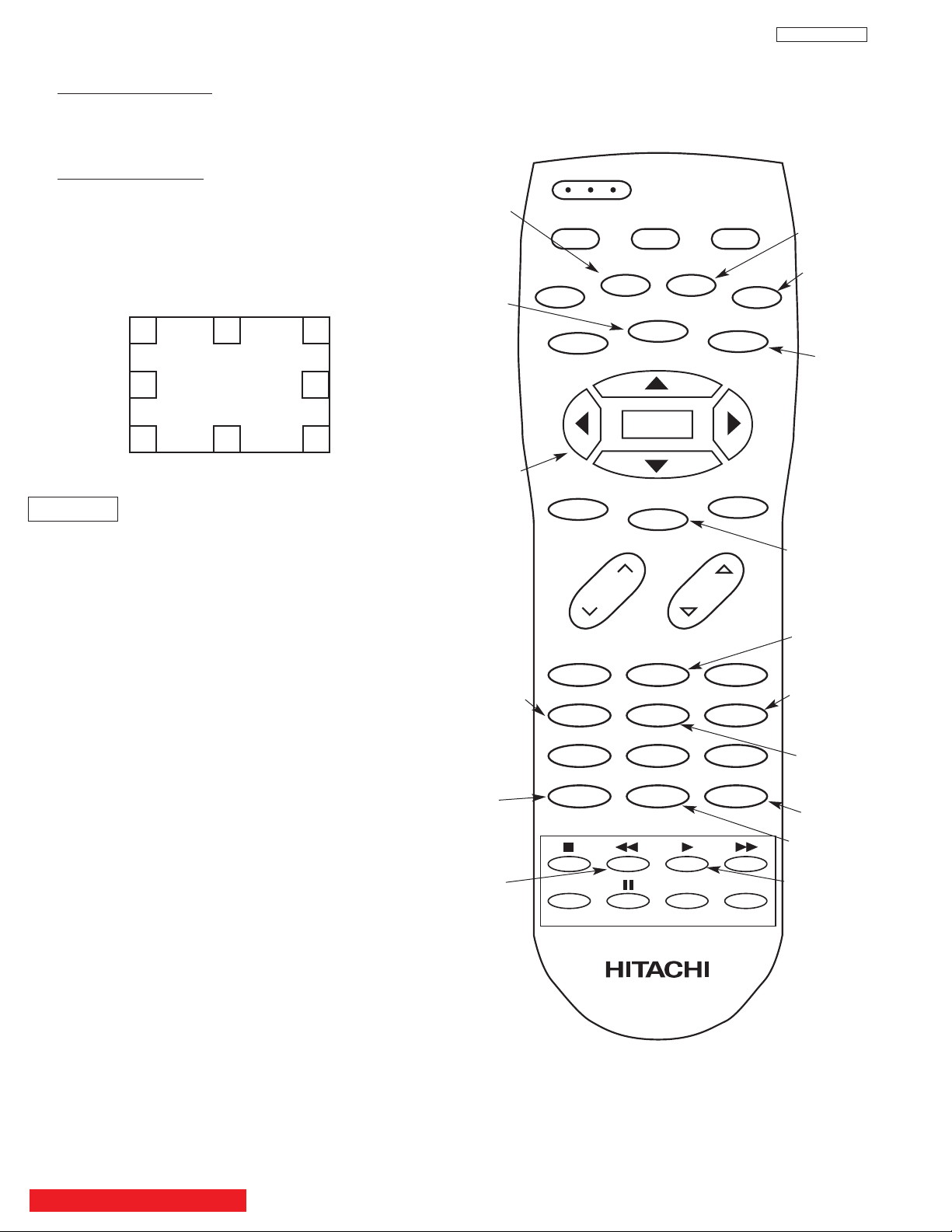
DP23/23G/24
Digital Convergence Remote Control
123
456
789
0
ANT INFO
VOL CH
POWER
TV CBL/SAT DVD/VCR
PIP
SWAP PIP MODE
FREEZE
VIDEO
PIP CH
MENU
MUTE
EXIT
LAST CH
REC
ASPECT
VIRTUAL HD
SELECT
CLU-4321UG
VID1
VID2
VID3 VID4
VID5
ROM READ
PHASE
CALCULATION
R/C must be in
VCR mode.
GREEN
ADJUSTMENT
CURSOR LEFT
CURSOR
DOWN
BLUE
(13x9)
REMOVE
COLOR
ROM WRITE
RASTER
POSITION
CROSSHATCH
VIDEO
CURSOR UP
CURSOR
RIGHT
RED
(7x5)
INITIALIZE
2.7.6 Magic Focus Initialize
Adjustment Preparation
(1) Receive any NTSC signal.
(2) Digital convergence adjustment should have been
completed.
(3) Set is in DCU adjustment mode.
Adjustment Procedure
(1) Press “PIP MODE” and then “PIP CH” to initialize
Magic Focus. The initialize operation starts and
several windows appear during this operation. It
takes about 30 seconds or less.
(2) When green dots appear, initialize operation is
finished.
(3) Turn power OFF on TV set.
REMARKS
Another way to start the initialize operation:
(1) Press “SERVICE ONLY” Sw. on DEF./CONV. PWB to
set DCU adj. mode.
(2) Press [PIP MODE] key on R/C. Then “ROM
WRITE?” is displayed for alarm. Next, press [PIP
CH] key on R/C to start initialization. When green
dots appear, initalization operation is finished.
NOTE: If there is an error message, red dots or an error
code, refer to page 57, CONVERGENCE
ERRORS.
Initialization Operation
BACK TO ADJUSTMENTS
*INITIAL:N*
29
DP23/23G/24
Condition: User controls are set to the initial set
positions (for shipment)
Measuring point-Screen center.
STICKING OUT OF BLUE
UNEVENNESS SPECIFICATION: ±1cd/m
2
Defocus sticking out specification
Screen Size Blue sticking out
43” 1.0mm
51” 1.0mm
57” 1.0mm
2.8 Blue defocus adjustment
Adjustment Preparation
(1) Optical and electrical focus adjustment should
have been completed.
(2) The convergence adjustment should have been
completed.
(3) Set Video conditions to factory preset.
(4) Input the cross-hatch signal.
Adjustment procedure
(1) Tu rn the B Focus VR (Focus Pack) fully
clockwise.
(2) Adjust sticking out level of blue to specification
shown in table below, by turning the (B) FOCUS
VR counter clockwise.
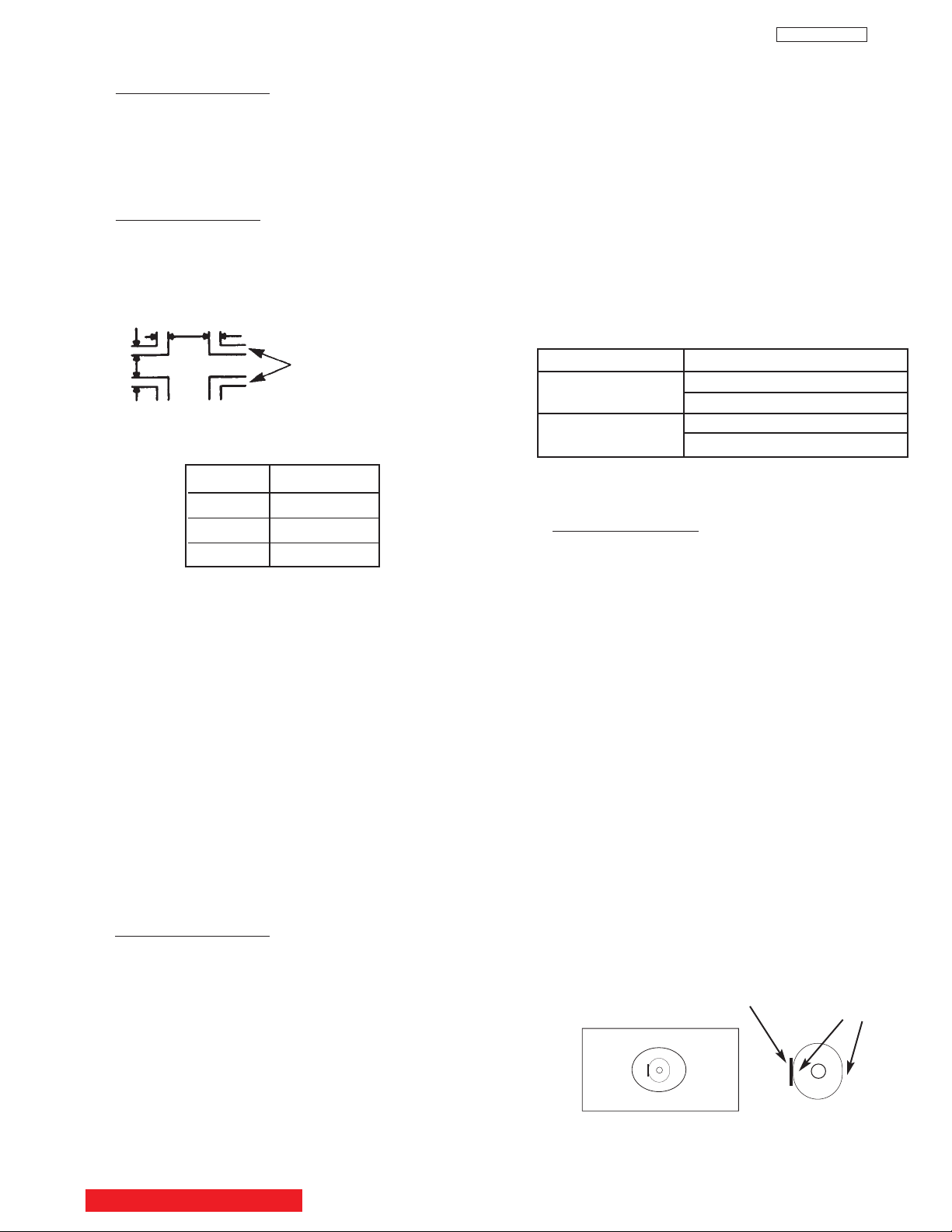
2.9 White balance adjustment
(1) Screen adjustment
(2) High light white balance.
(3) Low light white balance.
I
2
C data for High light white balance
Green : G DRIVE (HIGH) 3F (initial data)(Adjustable)
Red : R DRIVE (HIGH) 3F (initial data)(Adjustable)
Blue : on FOCUS PACK UFPK
I
2
C data for Low light white balance
Green : G CUT OFF (HIGH) 7F (initial) (Fixed data)
Red : R CUT OFF (HIGH) 7F (initial) (Adj. data)
Blue : B CUT OFF (HIGH) 7F (initial) (Adj. data)
Adjustment Prepar
ation
(1) Adjustment should start 20 min. or more after the TV
power is turned ON.
(2) CUT OFF ADJ. should be finished.
(3) VIDEO control : Contrast is MAX., Others are center.
(4) Color temp. : HIGH
(5) Signal:
* Hight Light white Balance Adj.
White raster 0.715Vpp (w/o sync., termination
incidence : 75ohm.) 100IRE
*Low Light white balance ADJ.
White raster 0.180Vpp (w/o sync., termination
incidence : 75ohm.) 25 IRE (The brightness
equal to 20cd/m
2
at screen center on 53” 4:3
model)
(6) BLUE defocus ADJ. should be finished.
(7) The vertical incident illumination on the screen
should be 20 Lux. or less.
(8) Picture Format is 16:9 Standard Mode.
(9) Sub Brightness adjustment should be finished.
(10)Go into I
2
C service mode.
Ta ble 1: White Balance Adjustment Signal
Ta ble 1 shows amplitude of White raster (without sync,
termination impedence: 75ohm).
Adjustment Procedure
A. High Light W/B adjustment
(1) Receive signal for High Light white balance ADJ.
(2) Adjust white balance to 10800K-7 MPCD
(x=0.278±0.004; y=0.280±0.004) at center of screen,
using R DRV/ G DRV with remote control.
B. Low Light W/B adjustment
(1) Receive signal for Low Light white balance ADJ.
(2) Adjust white balance to 21000K-25 MPCD (x
=0.260±0.010, y=0.245±0.010) at center of screen,
using R CUT OFF/G CUT OFF/B CUT OFF with
remote control. Do not touch screen VRs.
(3) Take Green color as a reference color, then adjust
Low Light W/B by increasing other two colors CUT
OFF data. Do not change GREEN CUT OFF data.
CA-100 Probe should be set to a direction as shown
below.
Repeat A & B two or three times, until no adjustment
is needed (white balance tracking-GOOD). If W/B
tracking is not good, set all data (Both DRV and CUT
OFF) to inital data, and change reference color to
different color.
Note: If Low Light adj. spec cannot be followed, apply
previous adj. spec. (adjust by eye.)
Screen Size 43” 51” 57”
High light [IRE] 100
[Vpp] 0.715
Low light [IRE] 15.0 17.5 20.0
[Vpp] 0.105 0.123 0.140
Set probe to above direction.
(Screw hole side should
be on the left side)
Top view of
CA-100 Probe
Screen
Screw Hole
Flat Face
BACK TO ADJUSTMENTS

30
DP23/23G/24
Adjustment preparation
(1) Start adjustment after the power is turned on for
20 minutes or more.
(2) The vertical incident illumination on the screen
should be 20 lux or less. (Room should be dark).
(3) Set the video settings (CONTRAST: max,
others: center) to standard condition.
(4) The blue defocus and cut off adjustments should
be completed.
(5) For low light white balance adjustment, input a
white raster signal level of 0.180 Vp-p (Video
input level).
(6) For high light white balance adjustment, input a
white raster signal level of 0.715Vp-p (Video
input level).
(7) Confirm R and G Drive (cool) data is 3F.
(8) Set Video Advanced Settings-Color Temp-
erature to HIGH.
Adjustment procedure
(1) Select the input signal for high brightness (Video
level = 0.715Vpp).
(2) Adjust the high brightness white balance by
changing I
2
C menu (R and B DRV HIGH mode
only).
(3) Select the signal for low brightness (Video level
= 0.105Vpp; 0.123 Vpp; 0.140Vpp)
(4) Adjust the low brightness white balance.
(5) Check that high brightness white balance is still
obtained. If it is not, return to step (2).
White balance = 10800° K -7 MPCD
Color coordinate = x …… 0.278±0.004
y …… 0.280±0.004
Normal: 7200˚K
Warm: 6500˚K
BACK TO ADJUSTMENTS
 Loading...