

Page 1
MAY 2002 HHEA-MANUFACTURING DIVISION
PA
No. 0160
51SWX20B DP27
57SWX20B DP27
65SWX20B DP27
57TWX20B DP27D
65TWX20B DP27D
R/C: CLU-5722TSI
CLU-121S
NN TT SS CC
DDPP2277 DDPP2277DD
CChhaassssiiss
SERVICE MANUAL
CONTENTS
IMPORTANT SAFETY INSTRUCTIONS . . . . . . . . . . . . . . . . . . . . . . . . . . . . . . . . . . . . 2
SERVICING PRECAUTIONS . . . . . . . . . . . . . . . . . . . . . . . . . . . . . . . . . . . . . . . . . . . . 6
TECHNICAL CAUTIONS . . . . . . . . . . . . . . . . . . . . . . . . . . . . . . . . . . . . . . . . . . . . . . 10
SPECIFICATIONS . . . . . . . . . . . . . . . . . . . . . . . . . . . . . . . . . . . . . . . . . . . . . . . . . . . 11
CIRCUIT PROTECTION . . . . . . . . . . . . . . . . . . . . . . . . . . . . . . . . . . . . . . . . . . . . . . 11
CAUTIONS WHEN CONNECTING/DISCONNECTING THE HV CONNECTOR . . . . . .12
GENERAL INFORMATION . . . . . . . . . . . . . . . . . . . . . . . . . . . . . . . . . . . . . . . . . . . . .13
REMOTE CONTROL . . . . . . . . . . . . . . . . . . . . . . . . . . . . . . . . . . . . . . . . . . . . . . . . .14
CUSTOMIZED PICTURE AND SOUND ADJUSTMENTS . . . . . . . . . . . . . . . . . . . . . .15
REAR PANEL CONNECTION . . . . . . . . . . . . . . . . . . . . . . . . . . . . . . . . . . . . . . . . . . .19
DISPLAY PICTURE FORMATS . . . . . . . . . . . . . . . . . . . . . . . . . . . . . . . . . . . . . . . . . .25
SERVICE ADJUSTMENTS . . . . . . . . . . . . . . . . . . . . . . . . . . . . . . . . . . . . . . . . . . . . .29
TROUBLESHOOTING . . . . . . . . . . . . . . . . . . . . . . . . . . . . . . . . . . . . . . . . . . . . . . . .60
WAVEFORMS . . . . . . . . . . . . . . . . . . . . . . . . . . . . . . . . . . . . . . . . . . . . . . . . . . . . . .63
DC VOLTAGE TABLES . . . . . . . . . . . . . . . . . . . . . . . . . . . . . . . . . . . . . . . . . . . . . . . .67
PROTECTION CIRCUIT BLOCK DIAGRAM . . . . . . . . . . . . . . . . . . . . . . . . . . . . . . . .83
CIRCUIT SCHEMATIC DIAGRAM . . . . . . . . . . . . . . . . . . . . . . . . . . . . . . . . . . . . . . . .85
PRINTED CIRCUIT BOARDS . . . . . . . . . . . . . . . . . . . . . . . . . . . . . . . . . . . . . . . . . . .96
BLOCK DIAGRAM . . . . . . . . . . . . . . . . . . . . . . . . . . . . . . . . . . . . . . . . . . . . . . . . . .108
WIRING DIAGRAM . . . . . . . . . . . . . . . . . . . . . . . . . . . . . . . . . . . . . . . . . . . . . . . . . .109
FINAL WIRING DRAWING . . . . . . . . . . . . . . . . . . . . . . . . . . . . . . . . . . . . . . . . . . . .110
TROUBLESHOOTING BLOCK DIAGRAMS . . . . . . . . . . . . . . . . . . . . . . . . . . . . . . .112
EXPLODED VIEW . . . . . . . . . . . . . . . . . . . . . . . . . . . . . . . . . . . . . . . . . . . . . . . . . .138
EXPLODED VIEW PARTS LIST . . . . . . . . . . . . . . . . . . . . . . . . . . . . . . . . . . . . . . . .144
REPLACEMENT PARTS LIST . . . . . . . . . . . . . . . . . . . . . . . . . . . . . . . . . . . . . . . . . .149
QUICK REFERENCE PARTS LIST . . . . . . . . . . . . . . . . . . . . . . . . . . . . . . . . . . . . . .177
DISASSEMBLY INSTRUCTIONS . . . . . . . . . . . . . . . . . . . . . . . . . . . . . . . . . . . . . . .178
DISASSEMBLY/ASSEMBLY INSTRUCTIONS FOR 65” SPLIT PTV . . . . . . . . . . . . . .183
CAUTION: These servicing instructions are for use by qualified service personnel only. To reduce the risk of
electric shock do not perform any servicing other than that contained in the operating instructions
unless you are qualified to do so. Before servicing this chassis, it is important that the service
technician read the “IMPORTANT SAFETY INSTRUCTIONS” in this service manual.
SAFETY NOTICE
USE ISOLATION TRANSFORMER WHEN SERVICING
Components having special safety characteristics are identified by a on the schematics and on the parts list in this
Service Data and its supplements and bulletins. Before servicing the chassis, it is important that the service technician
read and follow the “Important Safety Instructions” in this Service Manual.
PROJECTION COLOR TELEVISION
SPECIFICATIONS AND PARTS ARE SUBJECT TO CHANGE FOR IMPROVEMENT
!
TO GO TO A CHAPTER, CLICK ON ITS HEADING BELOW
Page 2

2
Components having special safety characteristics are identified by a on the schematics and on the parts list in this service
manual and its supplements and bulletins. Before servicing this chassis, it is important that the service technician read and
follow the “Important Safety Instructions” in this Service Manual.
For continued X-Radiation protection, replace picture tube with original type or Hitachi approved equivalent type.
This Service Manual is intended for qualified service technicians; it is not meant for the casual do-it-yourselfer. Qualified
technicians have the necessary test equipment and tools, and have been trained to properly and safely repair complex
products such as those covered by this manual.
Improperly performed repairs can adversely affect the safety and reliability of the product and may void warranty. If you
are not qualified to perform the repair of this product properly and safely, you should not risk trying to do so and refer the
repair to a qualified service technician.
WARNING
Lead in solder used in this product is listed by the California Health and Welfare agency as a known reproductive toxicant which
may cause birth defects or other reproductive harm (California Health and Safety Code, Section 25249.5).
When servicing or handling circuit boards and other components which contain lead in solder, avoid unprotected skin contact
with solder. Also, when soldering do not inhale any smoke or fumes produced.
This television receiver provides display of television closed captioning in accordance with section 15.119 of the FCC rules.
FEDERAL COMMUNICATIONS COMMISSION NOTICE
This equipment has been tested and found to comply with the limits for a Class B digital device, pursuant to Part 15 of the
FCC Rules. These limits are designed to provide reasonable protection against harmful interference in a residential
installation. This equipment generates, uses, and can radiate radio frequency energy and, if not installed and used in
accordance with the instructions, may cause harmful interference to radio communications. However, there is no guarantee
that interference will not occur in a particular installation. If this equipment does cause harmful interference to radio or
television reception, which can be determined by turning the equipment off and on, the user is encouraged to try to correct
the interference by one or more of the following measures:
• Reorient or relocate the receiving antenna.
• Increase the separation between the equipment and the receiver.
• Connect the equipment into an outlet on a circuit different from that to which the receiver is connected.
• Consult the dealer or an experienced radio/television technician for help.
IMPORTANT SAFETY INSTRUCTIONS
USE ISOLATION TRANSFORMER WHEN SERVICING
!
DP27/27D
Page 3
3
DP27/27D
IMPORTANT SAFETY INSTRUCTION
1. Before returning an instrument to the customer, always
make a safety check of the entire instrument, including
but not limited to the following items.
a. Be sure that no built-in protective devices are
defective and/or have been deleted during servicing.
(1) Protective shields are provided on this chassis to
protect both the technician and the customer.
Correctly replace all missing protective shields,
including any removed for servicing convenience. (2)
When reinstalling the chassis and/or other assembly
in the cabinet, be sure to put back in place all
protective devices, including but not limited to,
nonmetallic control knobs, insulating fishpaper,
adjustment and compartment covers/shields, and
isolation resistor/capacitor networks. Do not operate
this instrument or permit it to be operated without
all protective devices correctly installed and
functioning. Servicers who defeat safety features
or fail to perform safety checks may be liable for
any resulting damage.
b. Be sure that there are no cabinet openings through
which an adult or child might be able to insert their
fingers and contact a hazardous voltage. Such
openings include, but are not limited to (1) spacing
between the picture tube and cabinet mask, (2)
excessively wide cabinet ventilation slots, and (3) an
improperly fitted and/or incorrectly secured cabinet
back cover.
c. Antenna Cold Check – With the instrument AC plug
removed from any AC source, connect an electrical
jumper across the two AC plug prongs. Place the
instrument AC switch in the on position. Connect one
lead of an ohmmeter to the AC plug prongs tied
together and touch the other ohmmeter lead in turn to
each tuner antenna input, exposed terminal screw
and, if applicable, to the coaxial connector. If the
measured resistance is less than 1.0 megohms or
greater than 5.2 megohms, an abnormality exists that
must be corrected before the instrument is returned to
the customer. Repeat this test with the instrument AC
switch in the off position.
d. Leakage Current Hot Check – With the instrument
completely reassembled, plug the AC line cord
directly into a 120V AC outlet. (Do not use an isolation
transformer during this test.) Use a leakage current
tester or a metering system that complies with
American National Standards Institute (ANSI) C101.0
Leakage Current for Appliances and Underwriters
Laboratories (UL) 1410, (50.7). With the instrument
AC switch first in the on position and then in the off
position, measure from a known earth ground (metal
waterpipe, conduit, etc.) to all exposed metal parts of
the instrument (antennas, handle bracket, metal
cabinet, screw heads, metallic overlays, control
shafts, etc.), especially any exposed metal parts that
offer an electrical return path to the chassis. Any
current measured must not exceed 0.5 milliamps.
Reverse the instrument power cord plug in the outlet
and repeat test.
ANY MEASUREMENTS NOT WITHIN THE LIMITS
SPECIFIED HEREIN INDICATE A POTENTIAL
SHOCK HAZARD THAT MUST BE ELIMINATED
BEFORE RETURNING THE INSTRUMENT TO THE
CUSTOMER OR BEFORE CONNECTING THE
ANTENNA OR ACCESSORIES.
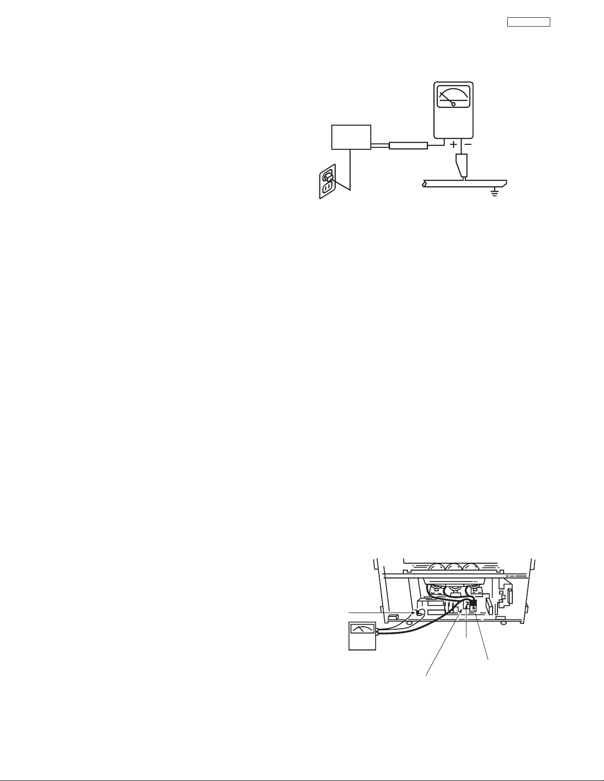
e. High Voltage – This receiver is provided with a hold
down circuit for clearly indicating that voltage has
increased in excess of a predetermined value.
Comply will all notes described in this Service Manual
regarding this hold down circuit when servicing, so
that this hold down circuit may correctly be operated.
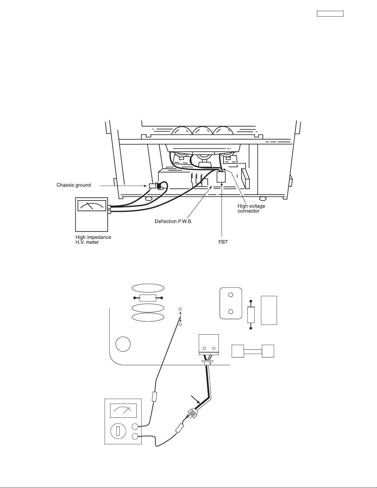
f. Service Warning – With maximum contrast, operating
high voltage in this receiver is lower than 30.5 kV. In
case any component having influence on high voltage
is replaced, confirm that the high voltage with
maximum contrast is lower than 30.5 kV.
To measure H.V. use a high impedance H.V. meter.
Connect (-) to chassis earth and (+) to the CRT anode
button. (See the following connection diagram.)
Note: Turn power switch off without fail before the
connection to the anode button is made.
LEAKAGE
CURRENT
TESTER
(READING
SHOULD NOT
BE ABOVE 0.5mA)
EARTH
GROUND
TEST ALL
EXPOSED
METAL SURFACES
DEVICE
UNDER
TEST
2-WIRE CORD
ALSO TEST WITH PLUG
REVERSED
(USING AC ADAPTER
PLUS AS REQUIRED)
AC Leakage Test
Chassis
ground
FBT
High Impedance
H.V. meter
Deflection P.W.B.
(TH01)
High voltage
connector
Page 4
4
DP27/27D
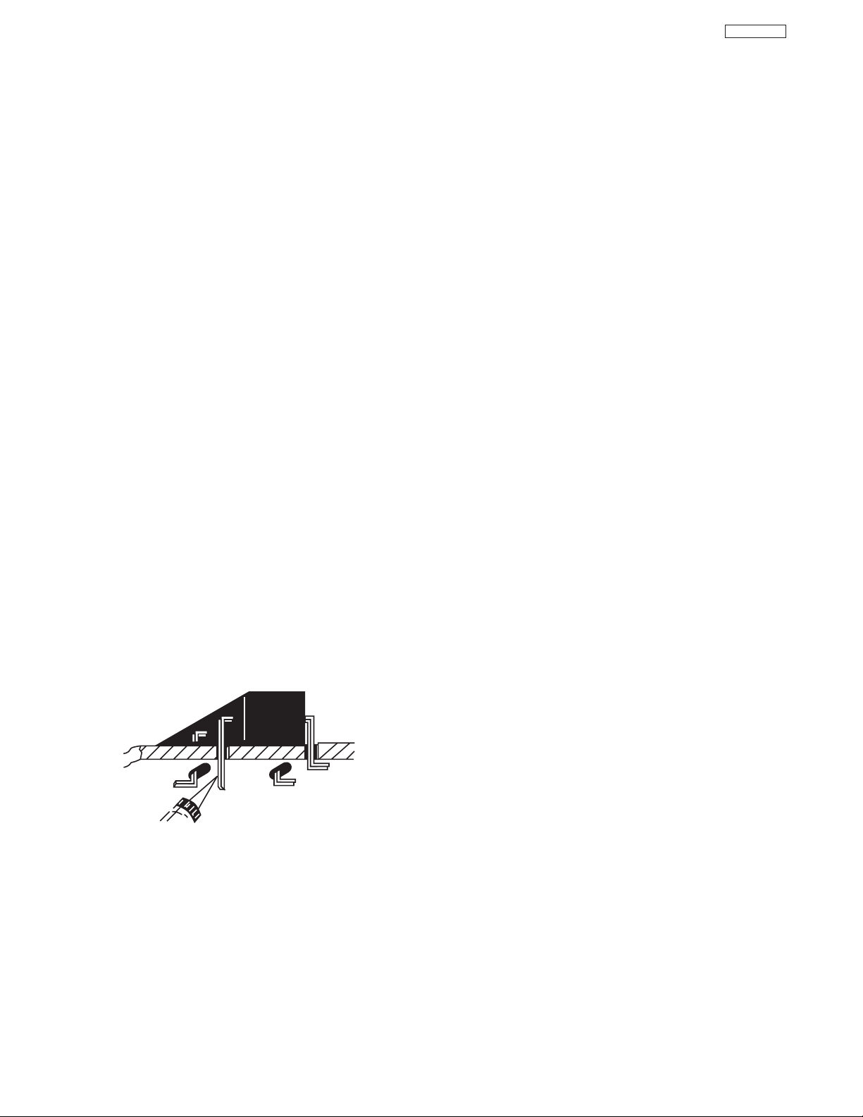
g. X-radiation – TUBE: The primary source of X-
radiation in this receiver is the picture tube. The tube
utilized for the above mentioned function in this
chassis is specially constructed to limit X-radiation
emissions.
For continued X-radiation protection, the replacement
tube must be the same type as the original, Hitachi
approved type.
When troubleshooting and making test measurements in a receiver with a problem of excessive high
voltage, avoid being unnecessarily close to the picture tube and the high voltage component.
Do not operate the chassis longer than is necessary
to locate the cause of excessive voltage.
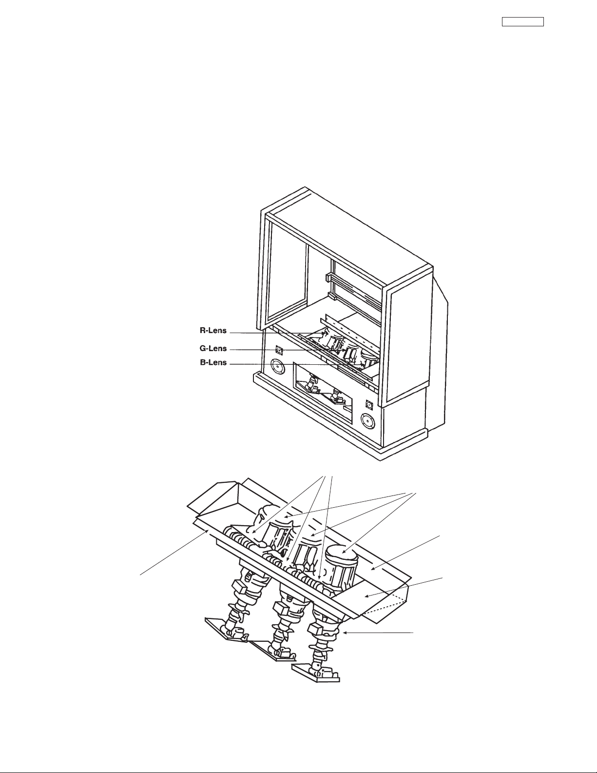
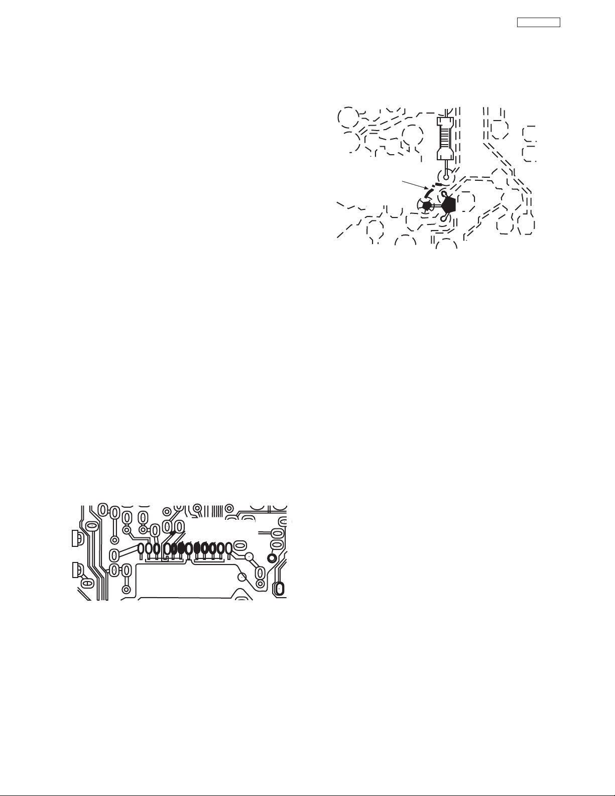
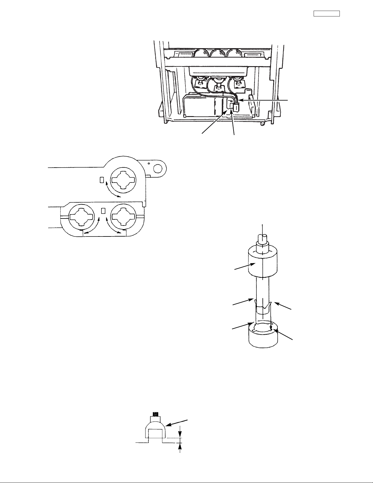
h. X-radiation Shield –
1. This receiver is provided with X-ray shield plates
for protection against X-radiation. Do not remove
X-ray shield plates A, B, or C shown in Fig. 1
unnecessarily, when troubleshooting and/or
making test measurements.
2. To prevent X-radiation, after replacement of
picture tube and lens, confirm these components
to be fixed correctly to bracket and cabinet, and
not to be taken off easily.
Shield Plate A
Glass Lens for Shielding
Shield Plate B
Shield Plate C
Shield Plate D
Detailing X-radiation shield
Shield Plate C
Fig. 1. Installation of shield lens, shield cover and shield plates (oblique view).
IMPORTANT SAFETY INSTRUCTIONS
Page 5

5
DP27/27D
2. Read and comply with all caution and safety-related
notes on or inside the receiver cabinet, on the
receiver chassis, or on the picture tube.
3. Design Alteration Warning – Do not alter or add to
the mechanical or electrical design of this TV receiver.
Design alterations and additions including but not
limited to circuit modifications and the addition of
items such as auxiliary audio and/or video output
connectors, might alter the safety characteristics of
this receiver and create a hazard to the user. Any
design alterations or additions may void the
manufacturer’s warranty and may make you, the
servicer, responsible for personal injury or property
damage resulting therefrom.
4. Picture Tube Implosion Protection Warning – The
picture tube in this receiver employs integral
implosion protection. For continued implosion
protection, replace the picture tube only with one of
the same type number. Do not remove, install, or
otherwise handle the picture tube in any manner
without first putting on shatterproof goggles equipped
with side shields. People not so equipped must be
kept safely away while picture tubes are handled.
Keep the picture tube away from your body. Do not
handle the picture tube by its neck.
5. Hot Chassis Warning – a. Some TV receiver chassis
are electrically connected directly to one conductor of
the AC power cord and may be safely serviced
without an isolation transformer only if the AC power
plug is inserted so that the chassis is connected to the
ground side of the AC power source. Confirm that the
AC power plug is inserted correctly with an AC
voltmeter by measuring between the chassis and a
known earth ground. If a voltage reading in excess of
1.0V is obtained, remove and reinsert the AC power
plug in the opposite polarity and again measure the
voltage potential between the chassis and a known
earth ground. b. Some TV receiver chassis normally
have 85V AC (RMS) between chassis and earth
ground regardless of the AC plug polarity. These
chassis can be safely serviced only with an isolation
transformer inserted in the power line between the
receiver and the AC power source, for both personnel
and test equipment protection. c. Some TV receiver
chassis have a secondary ground system in addition
to the main chassis ground. This secondary ground
system is not isolated from the AC power line. The two
ground systems are electrically separated by
insulating material that must not be defeated or
altered.
6. Observe original lead dress. Take extra care to assure
correct lead dress in the following areas: a. near
sharp edges, b. near thermally hot parts – be sure
that leads and components do not touch thermally hot
parts, c. the AC supply, d. high voltage and e. antenna
wiring. Always inspect in all areas for pinched, out-ofplate, or frayed wiring. Do not change spacing
between components and the printed circuit board.
Check AC power cord for damage.
7. Components, parts, and/or wiring that appear to have
overheated or are otherwise damaged should be
replaced with components, parts, or wiring that meet
original specifications. Additionally, determine the
cause of overheating and/or damage and, if
necessary, take corrective action to remove any
potential safety hazard.
8. PRODUCT SAFETY NOTICE – Many TV electrical
and mechanical parts have special safety-related
characteristics some of which are often not evident
from visual inspection, nor can the protection they
give necessarily be obtained by replacing them with
components rated for higher voltage, wattage, etc.
Parts that have special safety characteristics are
identified in Hitachi service data by shading on
schematics and by a in the parts list. Use of
substitute replacement that does not have the same
safety characteristics as the recommended replacement part in Hitachi service data parts list might
create shock, fire, and/or other hazards. Product
safety is under review continuously and new
instructions are issued whenever appropriate. For the
latest information, always consult the appropriate
current Hitachi service literature. A subscription to, or
additional copies of service literature may be obtained
at a nominal charge from Hitachi.
!
IMPORTANT SAFETY INSTRUCTIONS
Page 6

6
DP27/27D
CAUTION: Before servicing instruments covered by this
service data and its supplements and addenda, read and
follow the “Important Safety Instructions” on page 3 of this
publication.
NOTE: If unforeseen circumstances create conflict between
the following servicing precautions and any of the safety
precautions on page 3 of this publication, always follow the
safety precautions. Remember: Safety First.
General Servicing Guidelines
1. Always unplug the instrument AC power cord from the AC
power source before:
a. Removing or reinstalling any component, circuit
board, module, or any other instrument assembly.
b. Disconnecting or reconnecting any instrument
electrical plug or other electrical connection.
c. Connecting a test substitute in parallel with an
electrolytic capacitor in the instrument.
CAUTION: A wrong part substitution or incorrect
polarity installation of electrolytic
capacitors may result in an explosion
hazard.
d. Discharging the picture tube anode.
2. Test high voltage only by measuring it with an appropriate
high voltage meter or other voltage measuring device
(DVM, FETVOM, etc.) equipped with a suitable high
voltage probe. Do not test high voltage by “drawing an
arc.” The H.V. Distribution Box has an internal 400MΩ
resistor (bleeder resistor) connected from the high
voltage to ground. After power is removed from the
instrument the high voltage will discharge through the
high voltage bleeder resistor. If the tubes have high
voltage after power is removed, then the bleeder resistor
is defective or the bleeder ground is disconnected.
3. Discharge the picture tube’s anode at any of the R, G, or
B outputs on the H.V. Distribution Box only by (a) first
connecting one end of an insulated clip lead to the
degaussing or kine aquadag grounding system shield at
the point where the picture tube socket ground lead is
connected, and then (b) touch the other end of the
insulated clip lead to the picture tube high voltage
distribution box R, G, or B output, using an insulated
handle to avoid personal contact with high voltage.
4. Do not spray chemicals on or near this instrument or any
of its assemblies.
5. Unless specified otherwise in these service data, clean
electrical contracts by applying the following mixture to
the contacts with a pipe cleaner, cotton-tipped stick or
comparable nonabrasive applicator: 10% (by volume)
Acetone and 90% (by volume) isopropyl alcohol (90%99% strength).
CAUTION: This is a flammable mixture. Unless
specified otherwise in these service data,
lubrication of contacts is not required.
6. Do not defeat any plug/socket B+ voltage interlocks with
which instruments covered by this service data might be
equipped.
7. Do not apply AC power to this instrument and/or any of its
electrical assemblies unless all solid-state device heatsinks are correctly installed.
8. Always connect the test instrument ground lead to the
appropriate instrument chassis ground before connecting
the test instrument positive lead. Always remove the test
instrument ground lead last.
9. Use with this instrument only the test fixtures specified in
this service data.
CAUTION: Do not connect the test fixture ground strap
to any heatsink in this instrument.
Electrostatically Sensitive (ES) Devices
Some semiconductor (solid state) devices can be damaged
easily by static electricity. Such components commonly are
called Electrostatically Sensitive (ES) Devices. Examples of
typical ES devices are integrated circuits and some fieldeffect transistors and semiconductor “chip” components. The
following techniques should be used to help reduce the
incidence of component damage caused by static electricity.
1. Immediately before handling any semiconductor
component or semiconductor-equipped assembly, drain
off any electrostatic charge on your body by touching a
known earth ground. Alternatively, obtain and wear a
commercially available discharging wrist strap device,
which should be removed for potential shock reasons
prior to applying power to the unit under test.
2. After removing an electrical assembly equipped with ES
devices, place the assembly on a conductive surface
such as aluminum foil, to prevent electrostatic charge
buildup or exposure of the assembly.
3. Use only a grounded-tip soldering iron to solder or
desolder ES devices.
4. Use only can anti-static type solder removal device.
Some solder removal devices not classified as “antistatic” can generate electrical charges sufficient to
damage ES device.
5. Do not use freon-propelled chemicals. These can
generate electrical charges sufficient to damage ES
devices.
6. Do not remove a replacement ES device from its
protective package until immediately before you are
ready to install it. (Most replacement ES devices are
packaged with leads electrically shorted together by
conductive foam, aluminum foil or comparable conductive
material.)
7. Immediately before removing the protective material from
the leads of a replacement ES device, touch the
protective material to the chassis or circuit assembly into
which the device will be installed.
CAUTION: Be sure no power is applied to the chassis or
circuit, and observe all other safety
precautions.
8. Minimize bodily motions when handling unpackaged
replacement ES devices. (Otherwise harmless motion
such as the brushing together of your clothes fabric or the
lifting of your foot from a carpeted floor can generate
SERVICING PRECAUTIONS
Page 7
7
DP27/27D
General Soldering Guidelines
1. Use a grounded-tip, low-wattage soldering iron and
appropriate tip size and shape that will maintain tip
temperature within the range 500°F to 600°F.
2. Use an appropriate gauge of resin-core solder composed
of 60 parts tin/40 parts lead.
3. Keep the soldering iron tip clean and well-tinned.
4. Thoroughly clean the surfaces to be soldered. Use a
small wire-bristle (0.5 inch or 1.25 cm) brush with a metal
handle. Do not use freon-propelled spray-on cleaners.
5. Use the following desoldering technique.
a. Allow the soldering iron tip to reach normal
temperature (500°F to 600°F).
b. Heat the component lead until the solder melts.
Quickly draw away the melted solder with an antistatic, suction-type solder removal device or with
solder braid.
CAUTION: Work quickly to avoid overheating the
circuit board printed foil.
6. Use the following soldering technique.
a. Allow the soldering iron tip to reach normal
temperature (500°F to 600°F).
b. First, hold the soldering iron tip and solder strand
against the component lead until the solder melts.
c. Quickly move the soldering iron tip to the junction of
the component lead and the printed circuit foil, and
hold it there only until the solder flows onto and
around both the component lead and the foil.
CAUTION: Work quickly to avoid overheating the
circuit board printed foil or components.
d. Closely inspect the solder area and remove any
excess or splashed solder with a small wire-bristle
brush.
Removal
1. Desolder and straighten each IC lead in one operation by
gently prying up on the lead with the soldering iron tip as
the solder melts.
2. Draw away the melted solder with an anti-static suctiontype solder removal device (or with solder braid) before
removing the IC.
Replacement
1. Carefully insert the replacement IC in the circuit board.
2. Carefully bend each IC lead against the circuit foil pad
and solder it.
3. Clean the soldered areas with a small wire-bristle brush.
(It is not necessary to reapply acrylic coating to areas.)
“Small-signal” Discrete Transistor Removal/Replacement
1. Remove the defective transistor by clipping its leads as
close as possible to the component body.
2. Bend into a “U” shape the end of each of three leads
remaining on the circuit board.
3. Bend into a “U” shape the replacement transistor leads.
4. Connect to replacement transistor leads to the
corresponding leads extending from the circuit board and
crimp the “U” with long nose pliers to insure metal to
metal contact, then solder each connection.
Power Output Transistor Devices Removal/Replacements
1. Heat and remove all solder from around the transistor
leads.
2. Remove the heatsink mounting screw (if so equipped).
3. Carefully remove the transistor from the circuit board.
4. Insert new transistor in circuit board.
5. Solder each transistor lead, and clip off excess lead.
6. Replace heatsink.
Diode Removal/Replacement
1. Remove defective diode by clipping its leads as close as
possible to diode body.
2. Bend the two remaining leads perpendicularly to the
circuit board.
3. Observing diode polarity, wrap each lead of the new
diode around the corresponding lead on the circuit board.
4. Securely crimp each connection and solder it.
5. Inspect (on the circuit board copper side) the solder joints
of the two “original leads”. If they are not shiny, reheat
them and, if necessary, apply additional solder.
Use Solding Iron to Pry Leads
IC Removal/Replacement
Some Hitachi unitized chassis circuit boards have slotted
holes (oblong) through which the IC leads are inserted and
then bent flat against the circuit foil. When holes are the
slotted type, the following technique should be used to
remove and replace the IC. When working with boards using
the familiar round hole, use the standard technique as
outlined in paragraphs 5 and 6 above.
SERVICING PRECATIONS
Page 8
8
DP27/27D
Fuses and Conventional Resistor Removal/Replacement
1. Clip each fuse or resistor lead at top of circuit board
hollow stake.
2. Securely crimp leads of replacement component around
stake 1/8 inch from top.
3. Solder the connections.
CAUTION: Maintain original spacing between the
replaced component and adjacent
components and the circuit board, to
prevent excessive component
temperatures.
Circuit Board Foil Repair
Excessive heat applied to the copper foil of any printed
circuit board will weaken the adhesive that bonds the foil to
the circuit board, causing the foil to separate from, or “liftoff,” the board. The following guidelines and procedures
should be followed whenever this condition is encountered.
In Critical Copper Pattern Areas
High component/copper pattern density and/or special
voltage/current characteristics make the spacing and
integrity of copper pattern in some circuit board areas more
critical than in others. The circuit foil in these areas is
designated as Critical Copper Pattern. Because Critical
Copper Pattern requires special soldering techniques to
ensure the maintenance of reliability and safety standards,
contact your Hitachi personnel.
At IC Connections
To repair defective copper pattern at IC connections, use the
following procedure to install a jumper wire on the copper
pattern side of the circuit board. (Use this technique only on
IC connections.)
1. Carefully remove the damaged copper pattern with a
sharp knife. (Remove only as much copper as absolutely
necessary.)
2. Carefully scratch away the solder resist and acrylic
coating (if used) from the end of the remaining copper
pattern.
3. Bend a small “U” in one end of a small-gauge jumper wire
and carefully crimp it around the IC pin. Solder the IC
connection.
4. Route the jumper wire along the path of the cut-away
copper pattern and let it overlap the previously scraped
end of the good copper pattern. Solder the overlapped
area, and clip off any excess jumper wire.
1. Remove the defective copper pattern with a sharp knife.
Remove at least 1/4 inch of copper, to ensure hazardous
condition will not exist if the jumper wire opens.
2. Trace along the copper pattern from both wire sides of
the pattern break and locate the nearest component
directly connected to the affected copper pattern.
3. Connect insulated 20-gauge jumper wire from the
nearest component on one side of the pattern break to
the lead of the nearest component on the other side.
Carefully crimp and solder the connections.
CAUTION: Be sure the insulated jumper wire is
dressed so that it does not touch
components or sharp edges.
Frequency Synthesis (FS) Tuning Systems
1. Always unplug the instrument AC power cord before
disconnecting or reconnecting FS tuning system cables
and before removing or inserting FS tuning system
modules.
2. The FS tuner must never be disconnected from the FS
tuning control module while power is applied to the
instrument.
3. When troubleshooting intermittent problems that might be
caused by defective cable connection(s) to the FS tuning
system, remove the instrument AC power as soon as the
defective connector is found and finish confirming the
bad connection with a continuity test. This procedure will
reduce the probability of electrical overstress of the FS
system semi-conductor components.
CRIMP AND
SOLDER
BARE JUMPER
WIRE
Install Jumper Wire and Solder
DEFECTIVE
COPPER
REMOVED
Insulated Jumper Wire
At Other Connections
Use the following technique to repair defective copper
pattern at connections other than IC Pins. This technique
involves the installation of a jumper wire on the component
side of the circuit board.
SERVICING PRECATIONS
Page 9
9
DP27/27D
Leadless Chip Components
(surface mount)
Chip components must be replaced with identical
chips due to critical foil track spacing. There are no
holes in the board to mount standard transistors or
diodes. Some chip capacitor or resistor board solder
pads may have holes through the board, however the
hole diameter limits standard resistor replacement to
1/8 watt. Standard capacitors may also be limited for
the same reason. It is recommended that identical
chip components be used. .
Chip resistors have a three digit numerical resistance
code -1st and 2nd significant digits and a multiplier.
Example: 162 = 1600 or 1.6KΩ resistor, 0 = 0Ω
(jumper).
Chip capacitors generally do not have the value
indicated on the capacitor. The color of the component
indicates the general range of the capacitance.
Chip transistors are identified by a two letter code. The
first letter indicates the type and the second letter, the
grade of transistor.
Chip diodes have a two letter identification code as
per the code chart and are a dual diode pack with
either
common anode or common cathode. Check the parts
list for correct diode number.
Component Removal
1. Use solder wick to remove solder from component
end caps or terminals.
2. Without pulling up, carefully twist the component
with tweezers to break the adhesive.
3. Do not reuse removed leadless or chip
components since they are subject to stress
fracture during removal .
Chip Component Installation
1. Put a small amount of solder on the board
soldering pads.
2. Hold the chip component against the soldering
pads with tweezers or with a miniature alligator
clip and apply heat to the pad area with a 30 watt
iron until solder flows. Do not apply heat for more
than 3 seconds
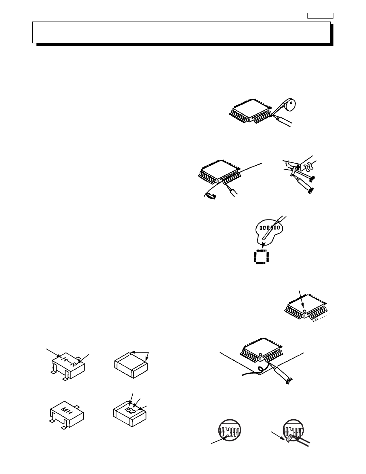
How to Replace Flat-lC
—Required Tools—
• Soldering iron • iron wire or small awl
• De-solder braids • Magnifier
1. Remove the solder from all of the pins of a Flat-lC
by using a de-solder braid.
2. Put the iron wire under the pins of the Flat-lC and
pull it in the direction indicated while heating the
pins using a soldering iron. A small awl can be
used instead of the iron wire.
3. Remove the solder from all of the pads of the
Fiat-lC by using
a de-solder braid.
4. Position the new Flat-lC in place (apply the pins of
the Flat-lC to the soldering pads where the pins
need to be soldered). Properly
determine the positions of the
soldering pads and pins by
correctly aligning the polarity
symbol.
6. Check with a magnifier for solder bridge between
the pins or for dry joint between pins and soldering
pads. To remove a solder bridge, use a de-solder
braid as shown in the figure below.
NOTE: These components are affixed with glue. Be careful not to break or damage any foil under the
component or at the pins of the ICs when removing. Usually applying heat to the component for a short
time while twisting with tweezers will break the component loose.
Chip Components
TYPE
GRADE
C
B
E
SOLDER
CAPS
TRANSISTOR
CAPACITOR
1ST DIGIT
2ND DIGIT
MULTIPLIER
= 1600 = 1.6K
ANODES
MH DIODE
RESISTOR
SOLDER CAPS
COMMON CATHODE
De-Solder
Braid
Soldering
Iron
Soldering
Iron
Soldering
Iron
Soldering
Iron
Soldering
Iron
Soldering
Iron
De-Solder
Braid
Flat-IC
Bridge
Solder
De-Solder
Braid
Iron
Wire
Pull
Awl
Polarity Symbol
5. Solder all pins to the soldering pads using a fine
tipped soldering iron.
SERVICING PRECATIONS
Page 10
10
DP27/27D
High Voltage limiter circuit operation check.
1. Turn off TV and connect jig as shown in Figure 2. Adjust
jig fully counter-clockwise for minimum resistance.
2. Set the AC input to 120V AC and turn on TV.
3. Confirm test pattern on CRT is a usable picture, then
slowly adjust jig until the picture disappears and TV shuts
down.
4. When the limiter circuit is operating properly, High
Voltage will be less than 30.5 kV at 1.4mA when TV shuts
down.
5. Turn off set immediately after checking circuit operation.
6. Unplug set for one minute to reset shutdown circuit.
Remove jig and voltmeter.
TECHNICAL CAUTIONS
(TH01)
WHITE side
GND side
TESTER
C901
R901
EF901
EF901
F901
KP01
PA
1
2
X901
R903
C981
R980
AC CORD POLARITY
This check is based on the UL standard. Use the jigs specified by the production technology section. The GND side (wider
blade) of the AC power cord should be connected to K9Y1
Page 11
11
DP27/27D
Models: 65SWX20B 65TWX20B
57SWX20B 57TWX20B
51SWX20B
Cathode-Ray Tube:
51SWX20B R=P16LXT00RFA01(U)
57SWX20B G=P16LXT00HHA01(U)
65SWX20B B=P16LXT00BMB01(U)
57TWX20B R=P16LXT00RFA01(U)
65TWX20B G=P16LXT00HHA01(U)
B=P16LXT00BMB01(U)
Power Input: 120 volts AC, 60 Hz
Power Consumption:
• Stand-By Power
51/57/65SWX20B . . . . . . . . . . . . . . . .1.3W
57/65TWX20B . . . . . . . . . . . . . . . . . . .1.3W
• Power Consumption (operating)
51/57/65SWX20B . . . . . . . . . . . . . . . .197W
57/65TWX20B . . . . . . . . . . . . . . . . . .197W
• Power Consumption (maximum)
51/57/65SWX20B . . . . . . . . . . . . . . . .248W
57/65TWX20B . . . . . . . . . . . . . . . . . .248W
Antenna Impedance: 75 Ohm Unbalanced
VHF / UHF / CATV
Receiving Channel: BAND CH
VHF 2~13
UHF 14~69
EXT. Mid (A-5)~(A-1), 4+
CATV Mid. A~I
CATV Super J~W
CATV Hyper (W+1)~(W+28)
CATV Ultra (W+29)~(W+84)
Intermediate Frequency: Picture l-F Carrier 45.75 MHz
Sound l-F Carrier 41.25 MHz
Color Sub Carrier 42.17 MHz
Video Input: 1 Volt p-p, 75 Ohm
Video Output: 1 Volt p-p, 75 ohm
Audio Input: 470 mVrms, 47 k Ohm
Stereo Audio Output: 470 mVrms, 1 k Ohm
Audio Output Power:
Front: 20 watts per channel at 10% distortion,
6 ohm Impedance. Max output – 40 watts.
Anode Voltage:
DP27/DP27D
30.2±0.3kv (1.20±0.2mA)
Brightness: 51” 57” 65”
(white screen) 220cd/m
2
180cd/m
2
140cd/m
2
Speakers: 2 Woofers - 5 inch (12 cm) round
2 Tweeters - 2 inch (5 cm) round
Dimension:
51” 57” 65”
Height (in.) 50 1/8 54 3/16 59 7/8
Width (in.) 44 1/2 54 1/64 61
Depth (in.) 25 1/32 25 1/32 28
Weight (Ibs.) 238 265 319
Circuit Board Assemblies:
C.P.T. (B) P.W.B. IR P.W.B.
C.P.T. (G) P.W.B. IR Sub P.W.B.
C.P.T. (R) P.W.B. Terminal P.W.B.
Power Supply P.W.B. Signal P.W.B.
Control P.W.B. Def/Convergence P.W.B.
Sensor Distribution P.W.B.
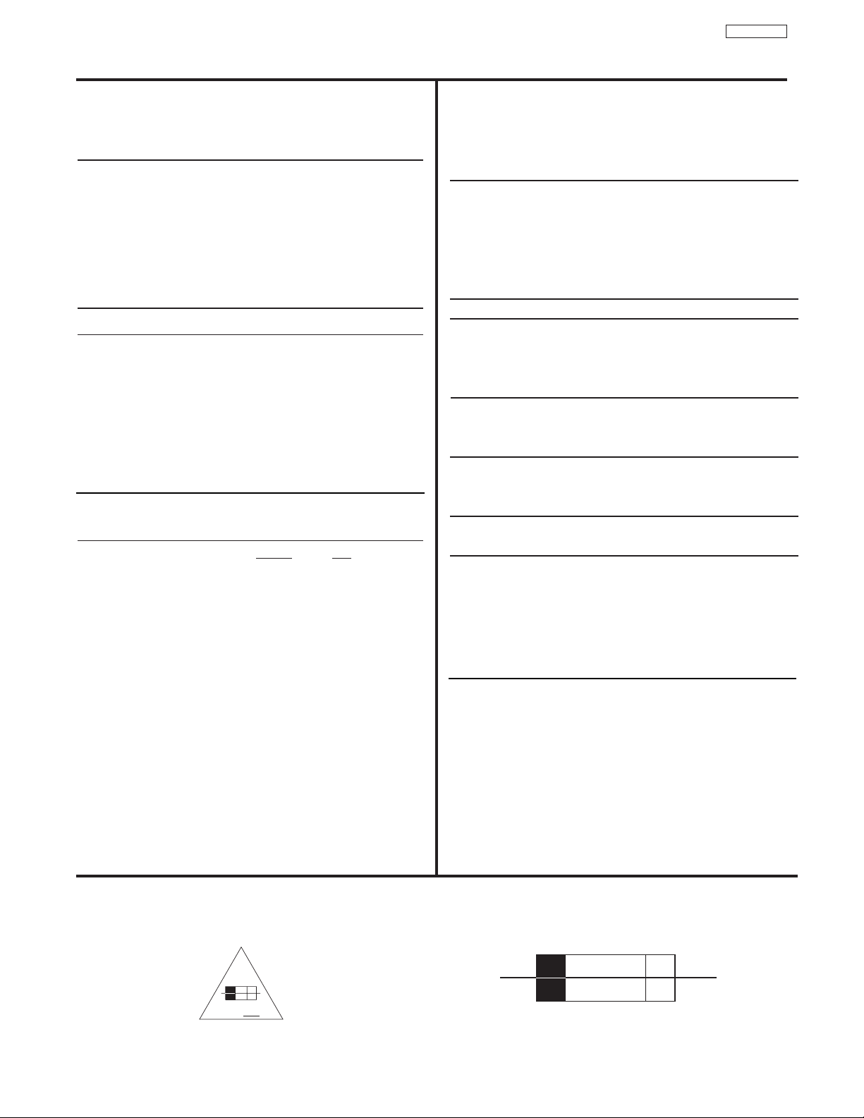
CIRCUIT PROTECTION
CAUTION: Below is an EXAMPLE only. See Replacement Parts List for details. The following symbol near the fuse
indicates fast operation fuse (to be replaced). Fuse ratings appear within the symbol.
Example:
SPECIFICATIONS
“RISK OF FIRE - REPLACE FUSE AS MARKED”
The rating of fuse F901 is 6A - 125V.
Replace with the same type fuse for continued protection
against fire.
F
6 A 125V
125V
6A
Page 12
12
DP27/27D
During Insertion
1. Please refer to direction for insertion as shown in Fig. B (L position). Insert connector until “CLICK” sound is heard.
2. Make sure the connector is pressed right in, so that it has a good contact with the spring.
3. Confirm the contact by pulling the connector slightly. (Don’t pull hard because it may damage the connector).
4. Cover the high voltage output by carefully pushing silicon cover onto it. (Don’t turn the connector).
(REMARK)
1. Make sure the silicon cover is
covering the high voltage output.
CAUTIONS WHEN CONNECTING / DISCONNECTING THE HV CONNECTOR
Perform the following when the
HV connector (anode connector)
is removed or inserted for CPT
replacement, etc.
Deflection P.W.B.
Silicon cover
Wing
L Position
L Position
Wing
FBT
Anode
connector
3. Remove the connector slowly
by pulling it away from the
case.
During Removal
1. Roll out silicon cover from FBT’s contact area slowly.
2. While turning the connector about 90 degrees
following the arrow (0 position), push the connector
slightly towards the case. (Fig. A)
Fig. A
Fig. B
Silicon Cover
less than 1mm
PUSH
PUSH
Page 13
13
DP27/27D
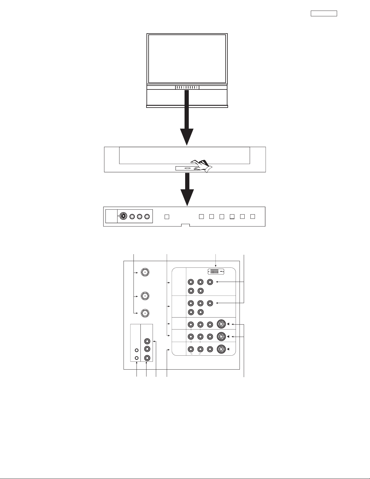
GENERAL INFORMATION
Antenna Input/Output S-VIDEO Inputs 3 and 4
Audio/Video Inputs 1, 2, 3 and 4 Component Input Y-P
BPR
MONITOR OUT IR BLASTER
AUDIO TO HI-FI Output DVI-HDTV Input (Input 1)
CENTER IN (Input)
P
B
P
R
CENTER
IN
P
B
P
R
DVI-HDTV
ANT A
TO
CONVERTER
ANT B
L
Y
R
(MONO)/L
IR
BLASTER
AUDIO
TO HI-FI
R
S-VIDEO
S-VIDEO
S-VIDEO
Y/VIDEO
R
(MONO)/L
R
(MONO)/L VIDEO
R
(MONO)/L VIDEO
R
L VIDEO
INPUT 1
INPUT 2
INPUT 3
INPUT 4
MONITOR
OUT
AUDIO
AUDIO
AUDIO
INPUT 5
S-VIDEO
VIDEO
-AUDIO-
L/MONO
R
EXIT
INPUT
SELECT
MENU
MAGIC FOCUS
VOL- VOL+ CH- CH+
POWER
PULL
FRONT CONTROL PANEL
REAR PANEL JACKS
Page 14
14
DP27/27D
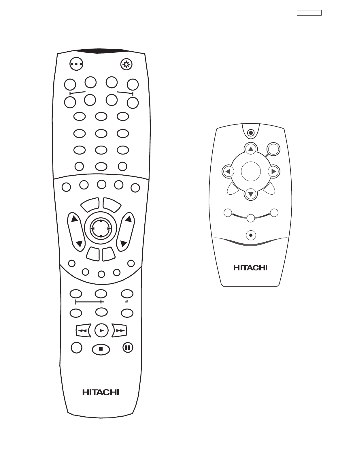
REMOTE CONTROL
POWER
TV
VCR
CBL
DVD
1
2
4
56
3
7
89
0
INFOSLEEP
A/V NET
EXIT
MENU
CHVOL
MUTE
PIP PIP CH
SWAP
FREEZE
PIP MODE
PIP ACCESS
VIDEO
SOURCE WIZARD
REC
SELECT
C.C.
ASPECT
STB
ANT
LAST CH
VCR PLUS+
SVCS
GUIDE/TV
SCHD
VID 1
VID 2
VID 3
VID 4
VID 5
TAPE
CD
AMP
VIRTUAL HD
CLU-5722TSI
CLU-5722TSI
CLU-120S
A/V NET
CH +
VOL -
VOL +
SELECT
MUTE
CH -
MENU
FAV CH
ANT
EXIT
POWER
Page 15
15
DP27/27D
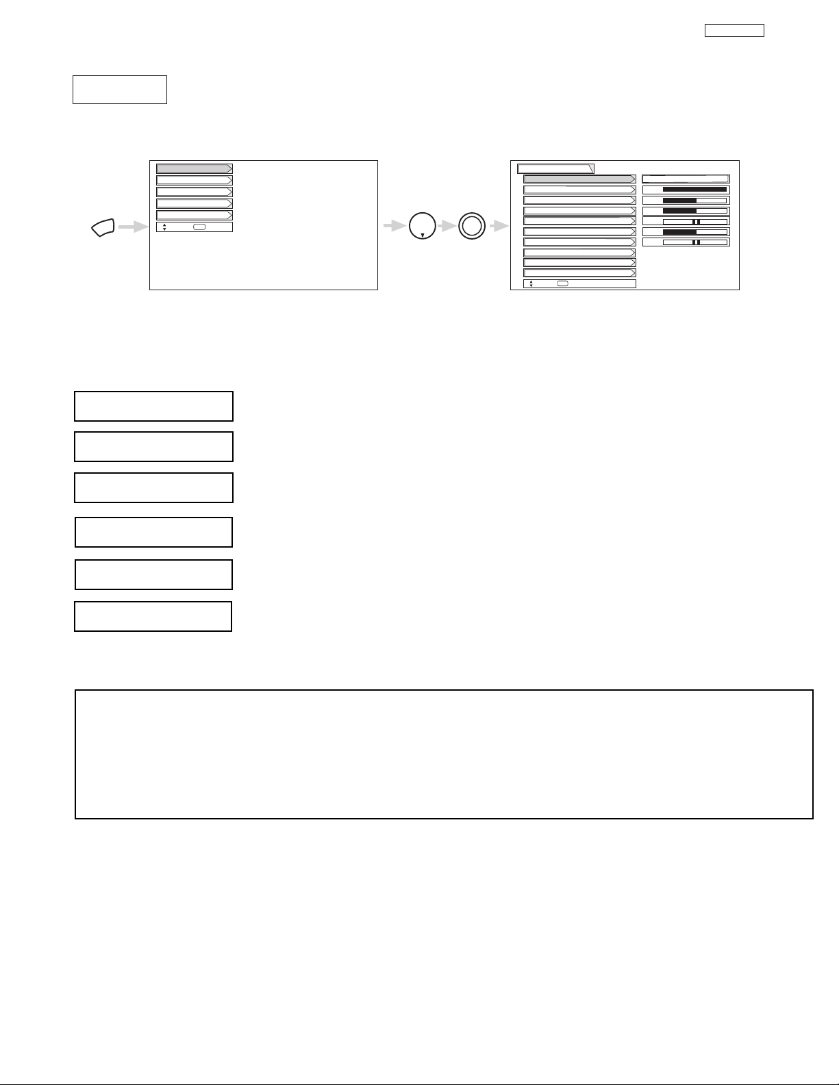
Select VIDEO to adjust picture settings and improve picture quality.
MENU
THUMB
STICK
THUMB
STICK
SELECT
Setup
Locks
Ch. Manager
Audio
Video
Move
SEL
Sel
Color
Brightness
Contrast
Picture Mode
Video
Move
SEL
Select
Vertical Position
Sharpness
Tint
Advanced Settings
Color System
100%
50%
50%
50%
0
Magic Focus
Sports
CUSTOMIZED PICTURE AND SOUND ADJUSTMENTS
Use this function to change the contrast between black and white levels in the picture. This adjustment
will only affect the picture when ADVANCED SETTINGS DIMMER is OFF.
Use the THUMB STICK or to highlight the function to be adjusted.
Press the THUMB STICK or to adjust the function. Press down on THUMB STICK to select the function settings.
Press MENU to return to main menu or select PICTURE MODE to return to previous menu.
Press EXIT to quit menu.
Use this function to adjust the level of color in the picture.
Use this function to adjust overall picture brightness.
This function allows you to select when aspect style is either 4:3 EXPANDED/ZOOM1/ZOOM2. Vertical
position can be changed with this mode. Adjustable range is -10 (video center is toward bottom of
screen) to +10 (video center is toward top of screen).
Contrast
Color
Brightness
Vertical Position
NOTES: 1. If CONTRAST is selected, you are adjusting CONTRAST. The additional menu items BRIGHTNESS, COLOR, TINT,
and SHARPNESS can be selected and adjusted in the same manner.
2. It may be necessary to adjust TINT to obtain optimum picture quality when using the COMPONENT VIDEO Y-PBP
R
input jacks.
3. If you are using the COMPONENT VIDEO input jacks (Y-PBPR) and notice that the TINT and COLOR are abnormal,
check to make sure that VIDEO- Color System is set properly.
Use this function to adjust flesh tones so they appear natural.
Tint
Use this function to adjust the amount of fine detail in the picture.
Sharpness
Video
Page 16
16
DP27/27D
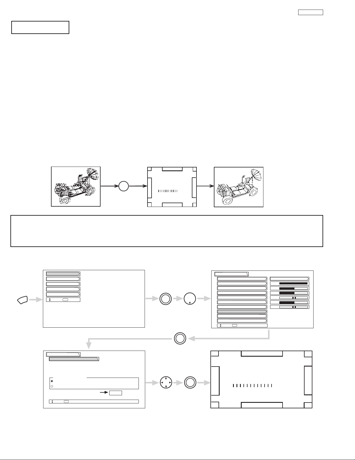
MAGIC
FOCUS
MAGIC FOCUS
Auto Digital Convergence Adjustment
Please turn ON your television for at least 20 minutes before using this feature.
The Magic Focus button will not work when Adjustment Mode is set to Manual (see page 17).
Your HITACHI Projection TV has three color projection tubes: one for red, one for green, one for blue. When mixed together in the
proper proportion, the output of these three color tubes can produce any color. To produce these colors, however, the beams must be
precisely aligned over each other so that the colors can be mixed. The process of aligning these picture beams is called “convergence”.
Over a period of time, the picture tubes can drift out of alignment due to normal bumps and vibrations or moving the TV. If you move
your TV, or if, after a time, you notice color rings or halos around objects in the picture, you may want to converge (align) the colors.
Properly converged, the lines appear white, which is actually a combination of the outputs of the three color tubes. The output of the
green tube is stationary. The outputs of the red and blue tubes can be adjusted. When properly aligned, the outputs of all three tubes
should be directly over each other to produce the white lines.
To simplify convergence, HITACHI incorporates a function called MAGIC FOCUS located on the front control panel, which allows the
TV to self-adjust. Press this MAGIC FOCUS button and the convergence self adjustment will start and this process will take
approximately 20 seconds. If this button is pressed during this process, no change in picture quality will occur. After this 20 second
self-adjust period, picture quality will be optimum. (Do not move the TV during self-adjust.)
You may also select Magic Focus from the VIDEO menu.
Magic Focus
NOTES: Only a momentary press of the MAGIC FOCUS button is necessary to start AUTO DIGITAL CONVERGENCE. At any
time during this convergence correction process, you may press the MAGIC FOCUS button to exit the MAGIC FOCUS
mode. However, the convergence correction process needs to be completed to SAVE the new corrected convergence
data.
Magic Focus
Video
Move
SEL
Return
Aligns the Red, Green, and Blue
colors to correct for Magnetic
Influences.
Auto
Manual
MENU
THUMB
STICK
THUMB
STICK
SELECT
Setup
Locks
Ch. Manager
Audio
Video
Move
SEL
Sel
Color
Brightness
Contrast
Picture Mode
Video
Move
SEL
Select
Vertical Position
Sharpness
Tint
Advanced Settings
Color System
100%
50%
50%
50%
Magic Focus
Sports
THUMB
STICK
SELECT
Adjustment Mode
If you want to adjust now
THUMB
STICK
THUMB
STICK
SELECT
Start
MAGIC FOCUS
CUSTOMIZED PICTURE AND SOUND ADJUSTMENTS
Page 17
17
DP27/27D
NOTES: 1. Please turn ON your television for at least 20 minutes before using this feature.
2. Auto Adjustment Mode is recommended. If convergence is still not acceptable, use the Manual Adjustment Mode.
DO NOT press MAGIC FOCUS or use Auto Adjustment Mode after using Manual Adjustment Mode.
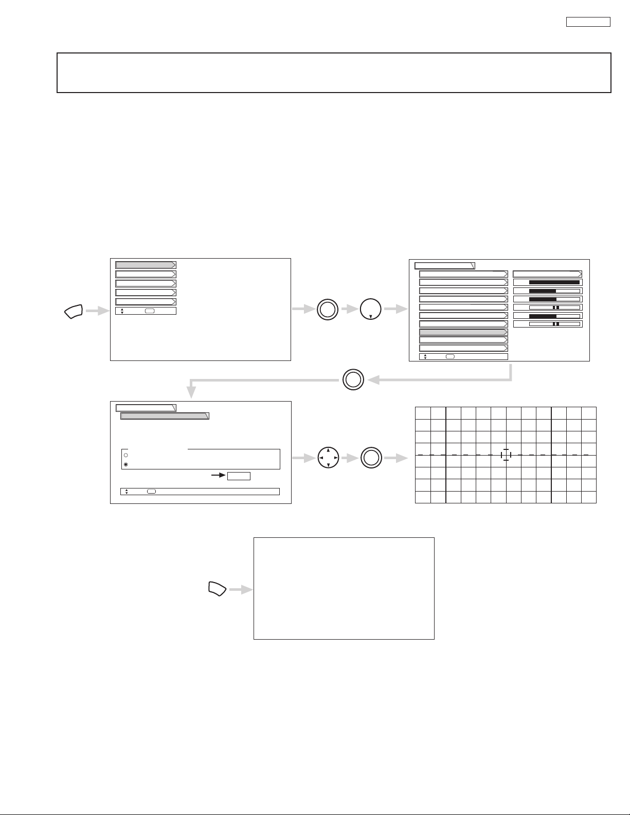
Manual Convergence Adjustment Mode
Using the Remote Control, select VIDEO-MAGIC FOCUS-MANUAL ADJUSTMENT MODE-START to access convergence crosshatch
pattern. The adjustment point is indicated by the Adjustment Point Cursor.
To Move Adjustment Point
To move adjustment point, the Adjustment Cursor must be WHITE. Use the THUMB STICK to move the Adjustment Cursor. Another
way to move the Adjustment Point Cursor is to press the followiing buttons: [2] up, [4] left, [5] down, [6] right. If you use the number
buttons while the adjustment point is WHITE, it will change to RED.
To Change the Color of Adjustment Point
Press the SELECT button repeatedly (WHITE-RED-BLUE-WHITE...). Green color is fixed and cannot be adjusted.
To Adjust the Convergence
Move the Adjustment Cursor to the point to be adjusted. Use the THUMB STICK to match the RED and BLUE colors to GREEN
(reference color). Properly aligned, all three colors should appear white.
If convergence is acceptable after Manual Convergence adjustment, press EXIT button to access menu mode.
Press the [1] button on the remote control to SAVE adjusted data and return to main picture.
Press the [2] button on the remote control to CANCEL adjusted data and return to main picture.
Press the [3] button on the remote control to recall the factory pre-set convergence data.
Press the [4] button on the remote control to return to the manual convergence adjustment mode (crosshatch pattern).
Press the [9] button on the remote control to read the SAVED data.
Magic Focus
Video
Move
SEL
Return
Aligns the Red, Green, and Blue
colors to correct for Magnetic
Influences.
Auto
Manual
MENU
THUMB
STICK
THUMB
STICK
SELECT
Setup
Locks
Ch. Manager
Audio
Video
Move
SEL
Sel
Color
Brightness
Contrast
Picture Mode
Video
Move
SEL
Select
Vertical Position
Sharpness
Tint
Advanced Settings
Color System
100%
50%
50%
50%
Magic Focus
Sports
THUMB
STICK
SELECT
Adjustment Mode
If you want to adjust now
THUMB
STICK
THUMB
STICK
SELECT
Start
EXIT
DONE : [1]
CANCEL : [2]
INI. RESET : [3]
BACK : [4]
CUSTOMIZED PICTURE AND SOUND ADJUSTMENTS
Page 18
18
DP27/27D
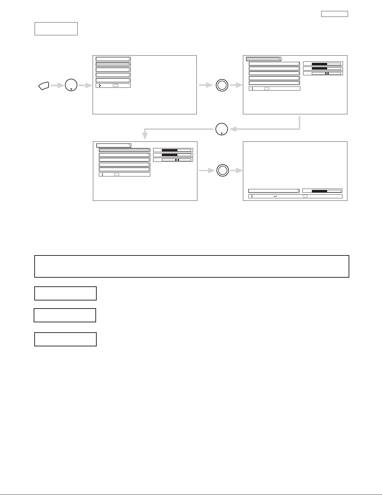
Select AUDIO to adjust the TV to your preference and to improve the sound quality.
Audio
MENU
THUMB
STICK
THUMB
STICK
SELECT
THUMB
STICK
SELECT
Setup
Locks
Ch. Manager
Audio
Video
Move
SEL
Sel
Next/Prev Change Value Return
SEL
Sound Enhancement
Balance
Bass
Treble
Audio
Move
SEL
Return
50%
50%
Sound Enhancement
Balance
Bass
Treble
Audio
Move
SEL
Select
50%
50%
Treble
50%
THUMB
STICK
Advanced Settings
Advanced Settings
LR
LR
This function controls the low frequency audio to all speakers.
Use THUMB STICK to highlight functions.
Press down on THUMB STICK to select the function setting.
Press THUMB STICK or to adjust the function.
Press EXIT to quit MENU, or select Audio to return to the main menu.
NOTE: If TREBLE is selected you are adjusting treble. The additional menu items Bass and Balance can be selected
and adjusted in the same manner.
This function controls the high frequency audio to all speakers.
This function will control the left to right balance of the TV internal speakers and the AUDIO TO HIFI output.
Bass
Balance
Treble
CUSTOMIZED PICTURE AND SOUND ADJUSTMENTS
Page 19
19
DP27/27D
P
B
P
R
CENTER
IN
P
B
P
R
DVI-HDTV
Outside antenna or
cable TV coaxial cable
2-Way signal splitter
Stereo System Amplifier
LR
INPUT
Laserdisc player, VCR,
camcorder, etc.
HDTV Set-Top Box
DVD Player
Cable TV Box
OUTPUT
INPUT
VCR #1
ANT
IN
OUTPUT
S-VIDEO
VLR
(Provided)
(Provided)
DIGITAL
OUTPUT CAPABILITY
ANT A
TO
CONVERTER
ANT B
L
Y
R
(MONO)/L
IR
BLASTER
AUDIO
TO HI-FI
R
S-VIDEO
S-VIDEO
S-VIDEO
Y/VIDEO
R
(MONO)/L
R
(MONO)/L VIDEO
R
(MONO)/L VIDEO
R
L VIDEO
INPUT 1
INPUT 2
INPUT 3
INPUT 4
MONITOR
OUT
DIGITAL OUTPUT
LR
OUTPUT
C
OUTPUT
YP
B/CBPR/CR
L R
VCR #2
V L R
OUTPUT
S-VIDEO
V L R
INPUT
S-VIDEO
OUTPUT
Y P
B
P
R
L R
CONNECT TO
IR BLASTER
CONNECT TO
IR BLASTER
AUDIO
AUDIO
AUDIO
IR
Sensor
IR
Sensor
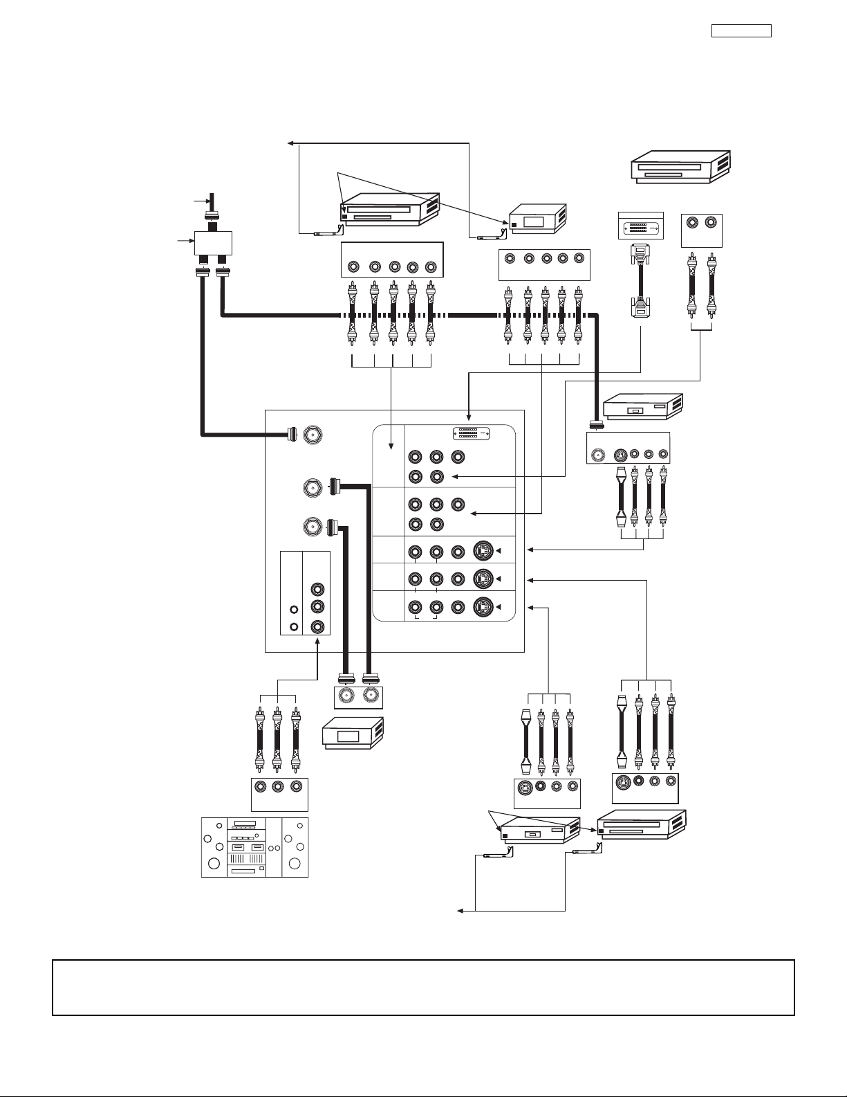
REAR PANEL CONNECTIONS
TYPICAL FULL-FEATURE SETUP
NOTE: 1.
Connect only 1 component to each input jack.
2. Follow connections that pertain to your personal entertainment system.
3. Standard video signal (composite video) can be input to all video inputs. (Video 1 ~ VIdeo 5).
Page 20
20
DP27/27D
REAR PANEL CONNECTIONS
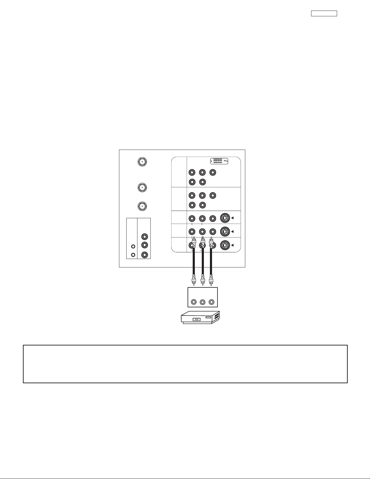
CONNECTING A STEREO SOURCE TO INPUT2~INPUT5
1. Connect the cable from the VIDEO OUT of the VCR or the laserdisc player to the INPUT (VIDEO) jack, as shown on the TV set
below.
2. Connect the cable from the AUDIO OUT R of the VCR or the laserdisc player to the INPUT (AUDIO/R) jack.
3. Connect the cable from the AUDIO OUT L of the VCR or the laserdisc player to the INPUT (AUDIO/L) jack.
4. Press the VID2~VID5 button to view the program from the VCR or laserdisc player. The VIDEO label disappears automatically
after approximately four seconds.
5. Press the ANT button to return to the previous channel.
NOTES: 1. Completely insert the connection cord plugs when connecting to rear panel jacks. The picture and sound that is
played back will be abnormal if the connection is loose.
2. A single VCR can be used for VCR #1 and VCR #2, but note that a VCR cannot record its own video or line
output. (INPUT: 3 in example on page 19) Refer to your VCR operating guide for more information on line
input-output connections.
P
B
P
R
CENTER
IN
P
B
P
R
DVI-HDTV
VCR
OUTPUT
RL V
ANT A
TO
CONVERTER
ANT B
L
Y
R
(MONO)/L
IR
BLASTER
AUDIO
TO HI-FI
R
S-VIDEO
S-VIDEO
S-VIDEO
Y/VIDEO
R
(MONO)/L
R
(MONO)/L VIDEO
R
(MONO)/L VIDEO
R
L VIDEO
INPUT 1
INPUT 2
INPUT 3
INPUT 4
MONITOR
OUT
AUDIO
AUDIO
AUDIO
Page 21
21
DP27/27D
REAR PANEL CONNECTIONS
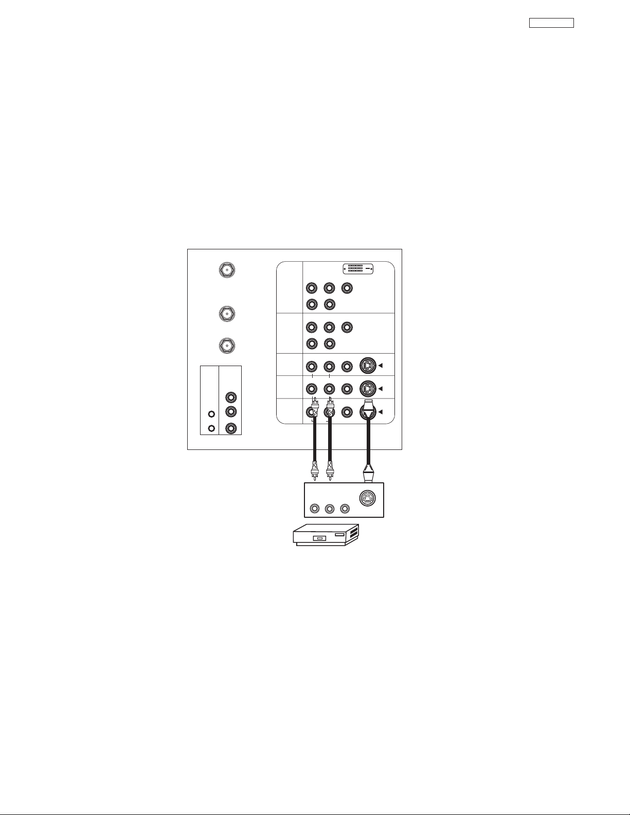
CONNECTING AN S-VIDEO SOURCE TO INPUT 3, 4 AND 5
1. Connect the cable from the S-VIDEO OUT of the VCR or the laserdisc player to the INPUT (S-VIDEO) jack, as shown on the TV
set below.
2. Connect the cable from the AUDIO OUT R of the VCR or the laserdisc player to the INPUT (AUDIO/R) jack.
3. Connect the cable from the AUDIO OUT L of the VCR or the laserdisc player to the INPUT (AUDIO/L) jack.
4. Press the VID3~VID5 button to view the program from the VCR or laserdisc player. The VIDEO label disappears automatically
after approximately four seconds.
5. Press the ANT button to return to the previous channel.
ANT A
DVI-HDTV
P
B
(MONO)/L
P
B
(MONO)/L
(MONO)/L VIDEO
(MONO)/L VIDEO
L VIDEO
AUDIO
Y
AUDIO
Y/VIDEO
AUDIO
S-VIDEO
S-VIDEO
S-VIDEO
IR
BLASTER
TO
CONVERTER
ANT B
AUDIO
TO HI-FI
CENTER
IN
L
R
INPUT 1
INPUT 2
INPUT 3
INPUT 4
MONITOR
OUT
P
R
R
P
R
R
R
R
R
OUTPUT
RL V
VCR
S-VIDEO
Page 22

22
DP27/27D
REAR PANEL CONNECTIONS
CONNECTING A COMPONENT SOURCE TO INPUT 1 OR 2: Y-PBPR.
1. Connect the cable from the Y OUT of the Laserdisc/DVD player or HDTV set top box
to the INPUT (Y) jack, as shown on the TV set at right.
2. Connect the cable from the CB/PBOUT or B-Y OUT of the Laserdisc/DVD player or
HDTV set top box to the INPUT (PB)jack.
3. Connect the cable from the CR/PROUT or R-Y OUT of the Laserdisc/DVD player or
HDTV set top box to the INPUT (PR) jack.
4. Connect the cable from the AUDIO OUT R of the Laserdisc/DVD player or HDTV set
top box to the INPUT (AUDIO/R) jack.
5. Connect the cable from the AUDIO OUT L of the Laserdisc/DVD player or HDTV set
top box to the INPUT (AUDIO/L) jack.
6. Press the VID1~VID2 button, to view the program from the Laserdisc/DVD player or
HDTV set top box. The VIDEO label disappears automatically after approximately
four seconds.
7. Press the ANT button to return to the previous channel.
P
B
P
R
CENTER
IN
P
B
P
R
DVI-HDTV
DVD Player
OUTPUT
P
RPB
Y
L R
AUDIO
AUDIO
ANT A
TO
CONVERTER
ANT B
L
Y
R
(MONO)/L
IR
BLASTER
AUDIO
TO HI-FI
R
S-VIDEO
S-VIDEO
S-VIDEO
Y/VIDEO
R
(MONO)/L
R
(MONO)/L VIDEO
R
(MONO)/L VIDEO
R
L VIDEO
INPUT 1
INPUT 2
INPUT 3
INPUT 4
MONITOR
OUT
CONNECTING A COMPONENT SOURCE WITH DVI-HDTV CAPABILITY TO INPUT 1
1. Connect the DVI connection cable from the output of the VCR or laserdisc player to the
DVI-HDTV input as shown on the TV set at right.
2. Connect the cable from the AUDIO OUT R of the VCR or the laserdisc player to the
INPUT (AUDIO/R) jack.
3. Connect the cable from the AUDIO OUT L of the VCR or the laserdisc player to the
INPUT (AUDIO/L) jack.
4. Press the VID1 button to view the program from the VCR or laserdisc player. The
VIDEO label disappears automatically after approximately four seconds.
5. Press the ANT button to return to the previous channel.
P
B
P
R
CENTER
IN
P
B
P
R
DVI-HDTV
ANT A
TO
CONVERTER
ANT B
L
Y
R
(MONO)/L
IR
BLASTER
AUDIO
TO HI-FI
R
S-VIDEO
S-VIDEO
S-VIDEO
Y/VIDEO
R
(MONO)/L
R
(MONO)/L VIDEO
R
(MONO)/L VIDEO
R
LVIDEO
INPUT 1
INPUT 2
INPUT 3
INPUT 4
MONITOR
OUT
DIGITAL
OUTPUT CAPABILITY
DIGITAL OUTPUT
LR
OUTPUT
AUDIO
AUDIO
AUDIO
Page 23

23
DP27/27D
FEATURE INFORMATION
As the digital era dawns, Hitachi has models that provide the best possible images today...and tomorrow. Our HDTV Ready
model incorporates new Flex Converter technology to display a high quality 1080i (high definition scanning) or 540P
(progressive scanning) image; this same circuitry enables it to accept a full 1080i HDTV signal from a digital set-top box now
or in the future.
FLEX CONVERTER TECHNOLOGY
With current analog broadcasts, there is just one level of picture quality. In the new age of digital TV, there will be several levels.
The highest, called HDTV, can be as high as 1080i.The next level, called HDTV, can be 720P. The standard level, SDTV, can
be 480P or 480i. Hitachi has developed the Flex Converter, advanced circuitry that allows your UltraVision TWX and SWX
series television to produce true 1080i HDTV resolution with an HDTV set-top box. It converts analog 480i signals to the
higher-quality 540P signals with no scan lines or flicker. The TWX and SWX needs a set-top box to receive any Digital Signal.
COMPONENT VIDEO
Component Video inputs accept separate blue, red & B/W signals from a high resolution digital source as DVD or digital settop box to provide a higher resolution picture.
3DYC (DIGITAL 3DYC COMB FILTER)
The Digital 3DYC Comb Filter analyzes three lines of information from a single video frame as well as lines from adjacent
frames. This technology eliminates the flickering that a detailed pattern or scene would normally cause, for the cleanest,
neatest picture possible.
PROGRESSIVE SCANNING
A standard TV uses Interlaced Scanning where each frame of video is broken into two fields, each providing alternating scan
lines. This can leave noticeable scan lines and cause flickering. With Progressive Scanning, complete frames are displayed for
a smoother picture with no scan lines and no flicker. This allows you to get the optimal picture quality from today’s high
resolution digital sources such as DVD or a digital set-top box.
Page 24

24
DP27/27D
ASPECT STYLE
ASPECT STYLE
Press the ASPECT button on the Remote Control to quickly change the ASPECT ratio.
Depending on the input signal, the picture format ratio allows you to adjust the images through the following options.
4:3 STANDARD Use this aspect mode to display conventional (4:3) images. Side panels (gray areas) are placed to the
left and right of the image to preserve the original aspect ratio of the source. Note: Use this mode for
only 15% of your total viewing time to prevent uneven aging of the phosphors. Phosphors in the lighted
area of the picture will age more rapidly than the gray areas.
4:3 EXPANDED Use this aspect mode to display conventional (4:3) sources by expanding the outer edges of the image
to fill the 16:9 screen. The center of the image remains unaltered.
4:3 Zoom1/Zoom2 Use these aspect modes to zoom in on conventional (4:3) sources.
16:9 STANDARD Use this aspect mode to display 16:9 sources like HDTV and DVD’s preserving the original 16:9 aspect
ratio.
16:9 Zoom Use this aspect to Zoom-in once while in 16:9 aspect.
V. POSITION
This function allows you to select when aspect style is either 4:3 EXPANDED/ZOOM1/ZOOM2. Vertical position can be changed with
this mode. Adjustable range is -10 (video center is toward bottom of screen) to +10 (video center is toward top of screen).
Page 25
25
DP27/27D
2525
Depending on the input signal, the picture format aspect ration allows you to adjust the image through the
following options.
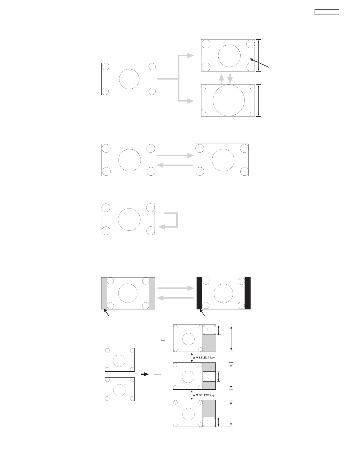
PICTURE FORMATS
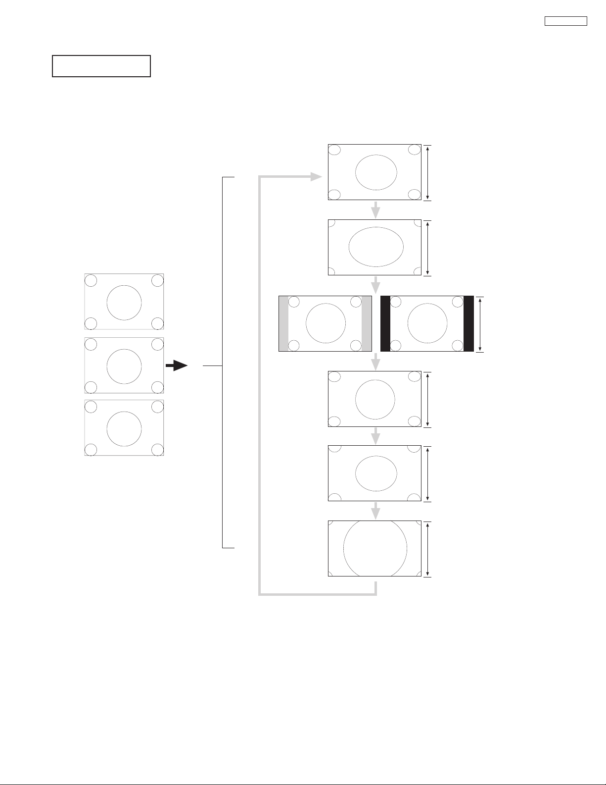
(1) NTSC: 4x3 (15.734KHz) ➔ 1080i/540p (33.716KHz)
SDTV: 480i 4x3 (15.734KHz/15.75KHz) ➔ 1080i/540p (33.716KHz/33.75KHz)
SDTV: 480p 4x3 (31.468KHz/31.5KHz) ➔ 1080i/540p (33.716KHz/33.75KHz)
Picture Format: 16:9 Standard, 16:9 Zoom, 4:3 Standard, 4:3 Exploded, 4:3 Zoom1, 4:3 Zoom2.
1080 Lines (Interlace)
540 Lines (Progressive)
4x3
NTSC
fH:15.75kHz
4x3
480i
fH:15.75kHz
16:9 Standard
1080i
540p
4x3
480p
fH:15.75kHz
1080 Lines (Interlace)
540 Lines (Progressive)
16:9 Zoom
1080i
540p
1080 Lines (Interlace)
540 Lines (Progressive)
4:3 Expanded
1080i
540p
1080 Lines (Interlace)
540 Lines (Progressive)
4:3 Zoom1
1080i
540p
1080 Lines (Interlace)
540 Lines (Progressive)
4:3 Zoom2
1080i
540p
Black Side Panel: OFF
Black Side Panel: ON
4:3 Standard
1080i
540p
1080 Lines (Interlace)
540 Lines (Progressive)
4:3 Standard
1080i
540p
Aspect Key
Aspect Key
Aspect Key
Aspect Key
Aspect Key
Aspect Key
ASPECT STYLE
Page 26
26
DP27/27D
1080 Lines (Interlace)
540 Lines (Progressive)
NTSC
Squeeze
16:9 Standard
1080i
540p
1080 Lines (Interlace)
540 Lines (Progressive)
16:9 Zoom
1080i
540p
1080 Lines (Interlace)
540 Lines (Progressive)
4:3 Expanded
1080i
540p
1080 Lines (Interlace)
540 Lines (Progressive)
4:3 Zoom1
1080i
540p
1080 Lines (Interlace)
540 Lines (Progressive)
4:3 Zoom2
1080i
540p
Black Side Panel: OFF
Black Side Panel: ON
4:3 Standard
1080i
540p
1080 Lines (Interlace)
540 Lines (Progressive)
Aspect Key
Aspect Key
Aspect Key
Aspect Key
Aspect Key
Aspect Key
4:3 Standard
1080i
540p
480i
16x9
540 (Progressive)
1080 (Interlaced)
16:9 Standard
1080i
540p
720p
16x9
540 (Progressive)
1080 (Interlaced)
16:9 Zoom
1080i
540p
Aspect Key
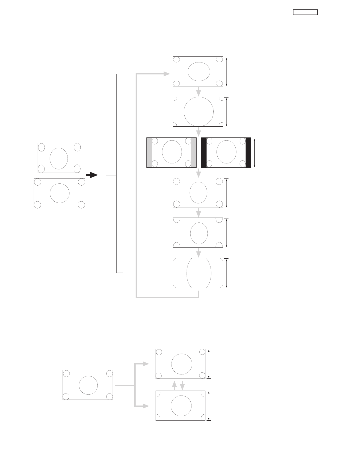
(2) NTSC: Squeeze (15.734KHz) ➔ 1080i/540p (33.716KHz)
SDTV: 480i 16x9 (15.734KHz/15.75KHz) ➔ 1080i/540p (33.716KHz/33.75KHz)
SDTV: 480p 16x9 (31.468KHz/31.5KHz) ➔ 1080i/540p (33.716KHz/33.75KHz)
Picture Format: 16:9 Standard, 16:9 Zoom, 4:3 Standard, 4:3 Exploded, 4:3 Zoom1, 4:3 Zoom2.
(3) HDTV: 720p 16x9 (44.995KHz/45KHz) ➔ 1080i/540p (33.716KHz/33.75KHz)
Picture Format: 16:9 Standard, 16:9 Zoom
ASPECT STYLE
Page 27
27
DP27/27D
1080 (Interlaced)
16:9 Standard
1080i
1080i
16x9
1080 (Interlaced)
16:9 Zoom
1080i
Aspect Key
1080i
540p
Virtual HD
1080i
Virtual HD
Menu Black Side Panel: OFF
Menu Black Side Panel: ON
Gray Side Panel
Black Side Panel
1080i Real Mode
(4) HDTV: 1080i 16x9 (33.716KHz/33.75KHz) ➔ 1080i (33.716KHz/33.75KHz)
Picture Format: 16:9 Standard, 16:9 Zoom
(5) Virtual HD Operation (Scanning Format)
a. NTSC, SDTV: 480i/480p, HDTV: 720p
b. HDTV: 1080i
(6) Black Side Panel Operation
a. NTSC, SDTV: 480i/480p, HDTV: 720p
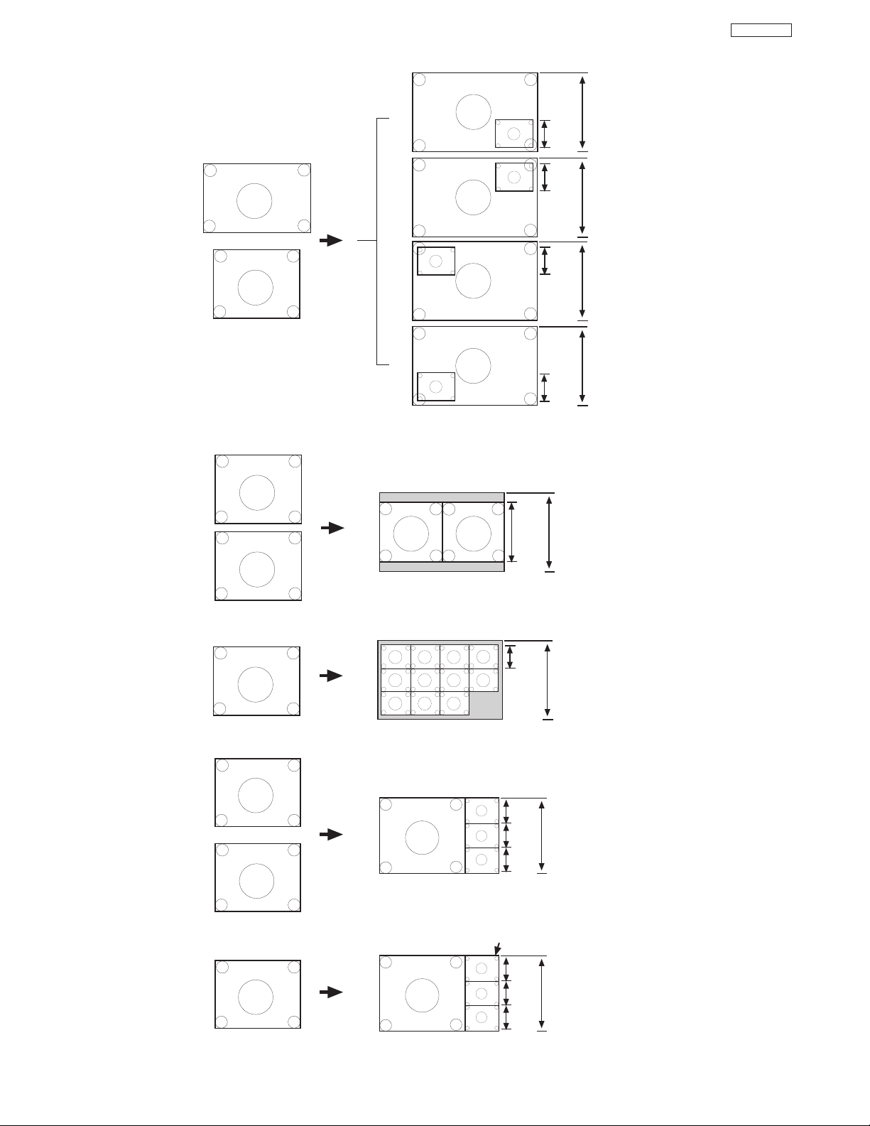
(7) Picture-in-Picture POP Mode
Main
Picture
180
Lines
SUB
Main
NTSC
480i
Sub
NTSC
480i
540
Lines
(Progressive)
Main
Picture
SUB
540
Lines
(Progressive)
180
Lines
Main
Picture
180
Lines
SUB
540
Lines
(Progressive)
ASPECT STYLE
Page 28
28
DP27/27D
(8) Picture-In-Picture PIP Mode
(9) Picture-In-Picture SPLIT Mode
(10) Picture-in-Picture SURF 11 Mode
(11) Picture-in-Picture SURF 3 Mode
(12) Picture-in-Picture STROBE Mode
Main
Picture
360
Lines
Main
1080i
Sub
NTSC
480i
1080
Lines
(Interlaced)
SUB
Main
Picture
360
Lines
1080
Lines
(Interlaced)
SUB
Main
Picture
360
Lines
1080
Lines
(Interlaced)
SUB
Main
Picture
360
Lines
1080
Lines
(Interlaced)
SUB
Sub
ALL
Main
334
Lines
540
Lines
(Progressive)
Main
ALL
Sub
SPLIT
167
Lines
540
Lines
(Progressive)
ANT A/B
NTSC
Main
ANT A
Sub
ANT A
Main
Picture
180
Lines
540
Lines
(Progressive)
SUB
SUB
SUB
180
Lines
180
Lines
NTSC
480i
Main
Picture
180
Lines
540
Lines
(Progressive)
SUB
SUB
SUB
180
Lines
180
Lines
STROBE
ASPECT STYLE
Page 29

29
DP27/27D
29
SERVICE ADJUSTMENTS
1. ASSEMBLED P.W.B ADJUSTMENT..................................................................................................................30
1-1. Service Menu Access (NTSC, SDTV and HDTV) ..................................................................................30
1-2. Comb Filter Operation Check ................................................................................................................35
1-3. Video Settings Check..............................................................................................................................35
1-3-1. Perfect Picture Check ..................................................................................................................35
1-3-2. Auto Color Check..........................................................................................................................35
1-3-3. Noise Reduction Check ................................................................................................................35
1-3-4. Color Temperature Check ............................................................................................................35
1-3-5. Velocity Modulation Check............................................................................................................35
1-3-6. Black Level Expansion Check ......................................................................................................35
1-4. High Voltage Adjustment ........................................................................................................................36
2. FINAL ASSEMBLY ADJUSTMENT (Adjustment should be according to below order) ..............................36
2-1. Cut Off Adjustment..................................................................................................................................36
2-2. DCU Phase Data Setting ......................................................................................................................36
2-3. Horizontal Position Adjustment (Coarse) ................................................................................................37
2-4. Raster Tilt (Deflection Yoke) ....................................................................................................................37
2-5. Beam Alignment......................................................................................................................................37
2-6. Raster Position........................................................................................................................................38
2-7. Vertical Size ..........................................................................................................................................38
2-8. Horizontal Size ......................................................................................................................................38
2-9. Beam Form ............................................................................................................................................39
2-10. Lens Focus..............................................................................................................................................39
2-11. Static Focus ............................................................................................................................................41
2-12. Digital Convergence ..............................................................................................................................41
2-12-1. Magic Focus Character Set Up ..................................................................................................42
2-12-2. Magic Focus Pattern Set Up ......................................................................................................43
2-12-3. Convergence Jig Screen Specification ......................................................................................44
2-12-4. Raster Position Adjsutment ........................................................................................................45
2-12-5. Convergence Point Adjustment ..................................................................................................45
2-13. Blue Defocus ..........................................................................................................................................47
2-14. White Balance ........................................................................................................................................47
2-15. Sub Brightness........................................................................................................................................48
2-16. Sub-Picture Signal Amplitude Adjustment ..............................................................................................50
2-17. Horizontal Position ................................................................................................................................51
2-18. Scanning Area Check ............................................................................................................................51
2-19. Raster Distortion Check ........................................................................................................................52
3. ADJUSTMENT POINT ........................................................................................................................................54
3-1. Signal Block Assembly............................................................................................................................55
3-2. Main Chassis Deflection P.W.B. ..............................................................................................................56
3-3. Power Supply P.W.B. ..............................................................................................................................57
3-4. CPT (R)(G)(B), Focus Pack ....................................................................................................................58
3-5. Control P.W.B. ........................................................................................................................................59
*IMPORTANT
For many of the above adjustments, it is necessary to have an HDTV (1080i or 720P) signal generator, SDTV (480P)
signal generator, as well as the usual NTSC (480i) signal generator.
Hitachi recognizes that few companies offer HDTV or SDTV signal generators and that the cost of these
generators is sometimes prohibitive. For this reason, we suggest the use of a set-top-box for HDTV and SDTV
adjustments. Usually, there is a switch on the set-top-box which enables it to output HDTV (1080i or 720P) or
SDTV (480P) signals even with no input. In this case, the sync is automatically detected by the TV (at the Y-P
BPR
Inputs on the rear panel).
TO GO TO AN ADJUSTMENT, CLICK ON ITS HEADING BELOW
Page 30

30
DP27/27D
3030
1. ASSEMBLED P.W.B. ADJUSTMENT
1.1 Service Menu Access
Adjustment Procedure
(1) Press and hold INPUT key on Control Panel and then press POWER key on control panel to access I2C
adjustment mode.
(2) Receive signal on main picture. (NTSC, SDTV or HDTV).
Some menu pages have I2C adjustments for SDTV and HDTV. The set will automatically allow you to set
these items only when a SDTV or HDTV signal is input to the COMPONENT jacks on the back of the TV. ......
See table below.
(3) Check the OSD according to table on pages 31~34, using THUMB STICK , on Remote Control.
*: Adjustable Data
Others: Fixed Data (be careful not to change)
(4) Press EXIT key to exit I2C ADJUST mode.
NOTE: (1) If the TV I2C data is different from the I2C Parameter (pages 31~34) for fixed data, change the data.
(2) When exchanging microprocessor or EEPROM and TV is turned on for first time, it requires
initialization of Memory Initial of I2C adjustment menu.
(3) Use FACTORY RESET to set TV to out of factory shipping conditions: Do not use MEMORY
INITIALIZE.
BACK TO ADJUSTMENTS
Page 31

31
DP27/27D
1.2 I
2
C Parameter List
(1) Adjust Mode OSD
Press INPUT + POWER
of control panel.
B CUT 7F
G CUT 7F
R CUT 7F
R DRV 3F
ADJUST MODE XXXXXXXX
SERVICE
SUB BRIGHT*
WHITE BALANCE
G DRIVE (HIGH)* 3F
R DRIVE (HIGH)* 3F
R CUTOFF (HIGH)* 7F
G CUTOFF (HIGH)* 7F
B CUTOFF (HIGH) 7F
H POSITION* 3F
V POSITION* 3F
FACT RESET
CH U/D, INPUT
ADJUST MODE
SERVICE
SUB BRIGHT
WHITE BALANCE
G DRIVE (HIGH) 48
R DRIVE (HIGH) 37
R CUTOFF (HIGH) 7F
G CUTOFF (HIGH) 7F
B CUTOFF (HIGH) 7F
H POSITION 12
V POSITION 00
FACT RESET
CH U/D, INPUT
Select SERVICE
and press key
Press EXIT key
CUT OFF ADJUST MODE
ADJUST MODE
SERVICE
SUB BRT
WHITE BAL
G DRIVE (HIGH) 3F
R DRIVE (HIGH) 3F
R CUTOFF (HIGH) 7F
G CUTOFF (HIGH) 7F
B CUTOFF (HIGH) 7F
H POSITION 3F
V POSITION 3F
FACT RESET
CH U/D, INPUT
MENU
Select SERVICE
and press key
Press EXIT key
G DRV 3F
MENU
MENU
Select SUB BRT
and press key
Press EXIT key
BRIGHTNESS 80
Press to adjust
VIDEO SETTINGS
(1) CONTRAST : MIN
(2) COLOR : MIN
VIDEO SETTINGS
(1) CONTRAST : MAX
(2) COLOR,TINT,SHARP,BRIGHT:CENER
(3) COLOR TEMP : COOL
ADJUST
(1) Press
to select the G DRV.,
R DRV., R CUT, G CUT, B CUT.
(Initial position G/B DRV). G/B
DRV, B/R DRV select by the DR R
and DR BG.
(2) Press
to adjust.
WHITE BALANCE
ADJ. MODE
INPUT + POWER
Only adjust
in cool mode.
Only adjust
in cool mode.
Only adjust
in cool mode.
A
SUB BRIGHT
ADJ. MODE
(DEFAULT)
BACK TO ADJUSTMENTS
Page 32

32
DP27/27D
ADJUST MODE
SERVICE
SUB BRIGHT*
WHITE BALANCE*
G DRIVE (HIGH)* 3F
R DRIVE (HIGH)* 3F
R CUTOFF (HIGH)* 7F
G CUTOFF (HIGH)* 7F
B CUTOFF (HIGH) 7F
H POSITION* 3F
V POSITION* 3F
FACT RESET
CH U/D, INPUT
CH U/D, INPUT
CH U/D, INPUT CH U/D, INPUT
CH U/D, INPUT
SELECT
SELECT
CH U/D, INPUT
WARM, NTSC, STD ADJ MODE
1. Press to select the G DRV or R DRV.
2. Press select to change the COOLWARM
NTSCCOOL mode. Adjust on each mode,
but cannot adjust on the COOL mode.
3. WARM and NTSC mode data is offset data
based on the COOL mode data.
CH U/D, INPUT
SELECT
MENU
SELECT
ADJUST MODE
SERVICE
SUB BRIGHT*
WHITE BALANCE*
G DRIVE (MEDUIM)* 50
R DRIVE (MEDUIM)* 55
R CUTOFF (HIGH)* 7F
G CUTOFF (HIGH)* 7F
B CUTOFF (HIGH) 7F
H POSITION* 3F
V POSITION* 3F
FACT RESET
ADJUST MODE
SERVICE
SUB BRIGHT*
WHITE BALANCE*
G DRIVE (STD)* 59
R DRIVE (STD)* 62
R CUTOFF (STD)* 7F
G CUTOFF (STD)* 7F
B CUTOFF (STD) 7F
H POSITION* 3F
V POSITION* 3F
FACT RESET
ADJUST MODE
SERVICE
SUB BRIGHT*
WHITE BALANCE*
G DRIVE (HIGH)* 3F
R DRIVE (HIGH)* 3F
R CUTOFF (HIGH)* 80
G CUTOFF (HIGH)* 80
B CUTOFF (HIGH) 80
H POSITION* 3F
V POSITION* 3F
FACT RESET
ADJUST MODE
SERVICE
SUB BRIGHT*
WHITE BALANCE*
G DRIVE (HIGH)* 3F
R DRIVE (HIGH)* 3F
R CUTOFF (HIGH)* 80
G CUTOFF (HIGH)* 80
B CUTOFF (HIGH) 80
H POSITION* 3F
V POSITION* 3F
FACT RESET
ADJUST MODE
SERVICE
SUB BRIGHT*
WHITE BALANCE*
G DRIVE (HIGH)* 3F
R DRIVE (HIGH)* 3F
R CUTOFF (HIGH)* 80
G CUTOFF (HIGH)* 80
B CUTOFF (HIGH) 80
H POSITION* 3F
V POSITION* 3F
FACT RESET
ADJUST MODE
SERVICE
SUB BRIGHT*
WHITE BALANCE*
G DRIVE (HIGH)* 3F
R DRIVE (HIGH)* 3F
R CUTOFF (HIGH)* 80
G CUTOFF (HIGH)* 80
B CUTOFF (HIGH) 80
H POSITION* 3F
V POSITION* 3F
FACT RESET
Other Mode 1080i through mode
Other Mode 1080i through mode
SELECT
VD Position Adj Mode
Press to adjust
H Position Adj Mode
Press to adjust
1.2 I
2
C Parameter List Cont.
BACK TO ADJUSTMENTS
Page 33

33
DP27/27D
Press to select.
Press to set to the
initial data of each
device.
MENU
SURF
mode
(ANT A only)
SPLIT
mode
POP/PIP
mode
NORMAL
mode
PIP
ON/OFF
key
PIP
Mode
key
PIP
Mode
key
PIP Mode key
ADJUST MODE
SUB CONT(TV-S) **
OSD POSITION
AFC/CLOCK TEST
MEMORY INIT
I2COPEN
IR BLASTER
ADJUST MODE
SUB CONT(TV-S) **
OSD POSITION
AFC/CLOCK TEST
MEMORY INIT
I2COPEN
IR BLASTER
H POSI **
V POSI **
CH U/D, INPUT
Press to select
the H POSI, V POSI
and press to
adjust.
Select OSD POSI
and press key.
Press EXIT key.
ADJUST MODE
SUB CONT(TV-S) **
OSD POSITION
AFC/CLOCK TEST
MEMORY INIT
I2COPEN
IR BLASTER
MENU
1.2 I2C Parameter List Cont.
NOTE: Memory Init. will reset all devices to factory settings. Use factory reset from previous page to restore unit to
factory settings condition.
BACK TO ADJUSTMENTS
Page 34

34
DP27/27D
DEVICE ADJUST
No. DATA
SYNCDET 00
F-STD 00
V-STD 00
H-STD 00
Select UPD64083
and press key.
Press EXIT key.
CH U/D, INPUT
DEVICE ADJUST
No. DATA
HSYNC-M 26
VSYNC-M 23
CSYNC-M 00
HSYNC-S 23
CH U/D, INPUT
MENU
Select TA1340F
and press key.
Press EXIT key.
ADJ
PUSH [SELECT]
ADJ
PUSH [SELECT]
UPD64083
TA1340F
DEVICE ADJUST
No. DATA
RGBOUTO 00
SUB-BRT 7F
G-DRV-H 3F
G-DRV-M 50
CH U/D, INPUT
MENU
Select TA1360N
and press key.
Press EXIT key.
ADJ
PUSH [SELECT]
TA1360N
DEVICE ADJUST
No. DATA
BBE-LO 07
BBE-HI 05
AGC 01
SURR 00
CH U/D, INPUT
MENU
Select AUDIO
and press key.
Press EXIT key.
ADJ
PUSH [SELECT]
AUDIO
DEVICE ADJUST
No. DATA
TVCINE 00
4X3DET 01
SN-DETH 00
SN-DETL 00
CH U/D, INPUT
MENU
Select FLEX
and press key.
Press EXIT key.
ADJ
PUSH [SELECT]
FLEX
DEVICE ADJUST
No. DATA
PSTRAT 05
PEND 00
TEND 00
BLCLN 01
CH U/D, INPUT
MENU
Select DIGITAL
MODULE and
press key.
Press EXIT key.
ADJ
PUSH [SELECT]
DIGITAL
MODULE
DEVICE ADJUST
No. DATA
SMPLING 00
POLLING 0F
START 02
TIMEOUT 05
CH U/D, INPUT
MENU
Select V CHIP
and press key.
Press EXIT key.
ADJ
PUSH [SELECT]
V CHIP
DEVICE ADJUST
No. DATA
WAIT 03
REPEAT 20
HFRQ-N 03
SYNCDET 00
CH U/D, INPUT
MENU
Select IR
BLASTER AND
press key.
Press EXIT key.
ADJ
PUSH [SELECT]
IR
BLASTER
DEVICE ADJUST
No. DATA
RGBOUTO 00
SUB-BRT 7F
G-DRV-H 3F
G-DRV-M 50
CH U/D, INPUT
MENU
Select ISF MODE
and press key.
Press EXIT key.
ADJ
PUSH [SELECT]
ISF MODE
CH U/D, INPUT
DEVICE ADJUST MODE
UPD64083
TA1340F
TA1360N
AUDIO
FLEX
DIGITAL MODULE
V CHIP
IR BLASTER
ISF MODE
MENU
1.2 I2C Parameter List Cont.
BACK TO ADJUSTMENTS
Page 35

35
DP27/27D
1.2 Comb filter operation check
Adjustment preparation
(1) Receive the color bar signal at the regular tuning
point.
(2) Set the CONTRAST control to MAX and the other
controls to center.
(3) Set the DIMMER to OFF.
Adjustment procedure
(1) Check that between the color bars there are line dots
every second color bar as shown in the drawing.
A
A A
B
3D Y/C
Dots
A None
B None
Check and line dots.
B
A
1.3 Video Settings (Advanced Settings)
1.3.1 Color Temperature
(1) Receive the Circle pattern signal.
(2) Set Color Temperature using THUMBSTICK ,
and change mode using THUMBSTICK , and
then press select button.
(3) Color Temperature is changed from Reddish to
medium and Standard from high.
1.3.2 Dimmer
(4) Receive the color bar signal.
(5) Select video mode by using THUMBSTICK ,.
(6) Press THUMBSTICK , to select advanced
settings then press THUMBSTICK .
(7) Select Dimmer using THUMBSTICK , and set it
ON by pressing SELECT.
(8) Check that display becomes dark when the front of
QM02 (light detect transistor on the control P.W.B.) is
covered with hands.
(9) Set Dimmer to OFF by pressing select button and
check that contrast of the display returns.
1.3.3 A
uto Color
(10)Set the color control to MAX.
(11)Select Auto Color using THUMBSTICK , and
then press select button.
(12)Set the Auto Color to OFF by pressing select button
and check that the red part of color bar signal grows
deeper.
(13)Reset Auto Color to ON by pressing select button.
(14)Reset the color control to Center.
(15)Receive the color bar signal
1.3.4 Noise Reduction
(16)Select noise reduction mode using THUMBSTICK
, and then press select button to set it ON and
check that the noise is reduced.
1.3.5
Velocity Modulation
(17)Select Velocity Modulation using THUMBSTICK ,
and press select button to ON.
(18)When the mode is ON, definition level is up at edge
of vertical line of the circle pattern.
1.3.6 Blac
k Level Expansion
(19)Select Black Level Expansion using THUMBSTICK
, and press select button to ON.
(20)When the mode is ON, Black level is sink at black
portion of picture.
1.3.7 Blac
k Side Panel
(21)Select Black Side Panel using THUMBSTICK ,
and press select button to set it to ON.
(22)When the mode is ON, the side panel is sink to black.
Aspect: 4:3 Normal Mode
Side Panel
BACK TO ADJUSTMENTS
Page 36

36
DP27/27D
Important: High Voltage adjustment should
NOT
be adjusted in field. This is
adjusted at factory using precise
loads and should NO
T be
readjusted.
1.4 High Voltage Adjustment (should NOT be
readjusted in field).
Adjustment preparation
(1) Connect High Voltage meter to FBT High Voltage
output. Connect GND of High Voltage meter to CPT
GND or FBT GND.
(2) Check that High Voltage adjustment VR (RH17) is
set to mechanical center. (located behind FBT on
DEFLECTION PWB).
(3) Receive circle pattern signal.
(4) VIDEO control should be reset.
Adjustment procedure
(1) Adjust High Voltage to following spec. by turning VR
RH17 slowly. ADJ. SPEC = 30.2KV±0.3kV.
(2) After adjustment, fix VR RH17 with Silicone glue
(KE40RTV).
2. FINAL ASSEMBLY ADJUSTMENT
2.1 Cut Off Adjustment
Adjustment preparation
(1) Adjust screen VR’s on Focus Pack fully
counterclockwise.
(2) Adjust Focus VR’s on Focus Pack fully
clockwise.
(3) Set video conditions to factory preset.
(4) The vertical incident illumination on the screen
should be 20 lux or less (room should be dark).
!
K
Adjustment procedure
(1) Press and hold INPUT key on control panel and
then POWER ON to access I
2
C adjustment
mode.
(2) Choose “SERVICE” item from I
2
C adjustment
menu by pressing THUMB STICK .
(3) Screen VR should be turned clockwise gradually
and set so that retrace line begins to appear.
(4) Return to “NORMAL” mode by THUMB STICK
again.
(5) Adjust Focus VR’s so that focus is even all
around screen.
2.2 DCU Phase Data Setting
Adjustment preparation
(1) Cut off adjustment should be finished.
(2) Set video conditions to factory preset.
Adjustment procedure
(1) Receive any NTSC signal.
(2) Push “SERVICE ONLY” SW on DEF./CONV.
PWB. (Enter to DCU ADJ. mode).
(3) Push A/V NET key on R/C. (Green cross hatch is
displayed).
Then push EXIT key on R/C. (Character pattern
is displayed. This is the PHASE setting mode).
(4) Set PH-H phase data as shown below by using
4 and 6 key on R/C.
(5) Set PH-V phase data as shown below by using
2 and 5 key on R/C.
(6) Set CR-H phase data as shown below by using
THUMB STICK and key on R/C.
(7) Set CR-V phase data as shown below by using
THUMB STICK and key on R/C.
(8) Push A/V NET key on R/C to exit from the
PHASE mode.
(9) Push PIP MODE key 2 times on R/C to write the
phase data to memory.
(10) When Green dots are displayed, push MUTE
key to return to DCU ADJ. mode.
(11)Push “SERVICE ONLY” SW to return to RF or
VIDEO mode.
PHASE MODE
PH-H :CD
PH-V: 04
CR-H: 35
CR-V: 0A
Static Focus VR
R
GB
R
GB
Screen VR
Focus VR
Screen VR
FOCUS PACK
BACK TO ADJUSTMENTS
High Voltage Adjustment VR.
RH17
(FBT)
TH01
DEFLECTION PWB.
CONV.
HEATSIN
Page 37

37
DP27/27D
2.3 Horiontal Position Adjustment (Coarse)
Adjustment preparation
(1) DCU PHASE DATA SETTING should be
finished.
Adjustment procedure
(1) Receive circle pattern (03ch.)
(2) Push SERVICE ONLY switch to display DCU
crosshatch. Mark the DCU crosshatch center
position using your finger tip.
(3) Push SERVICE ONLY switch again to exit from
the DCU crosshatch.
(4) Go to I
2
C ADJ. mode.
(5) Choose H. POSI item by using R/C MENU (or
up/down cursor) key. Adjust horizontal position
to match the circle center to DCU crosshatch
center (marked by your finger tip).
(6) Exit from I
2
C menu.
2.4 Raster Tilt adjustment (Deflection yoke)
Adjustment preparation
(1) The set can face east or west.
(2) Input the single cross test signal.
(3) Set CONTRAST to MAX, other controls to
CENTER.
(4) The lens focus and horizontal position
adjustment should have been coarse adjusted.
(5) The static focus should have been coarse
adjusted.
(6) The digital convergence RAM should be cleared
(uncorrected state). With the TV set off, press
and hold the “SERVICE ONLY” switch located on
the DEF./CONV. PWB and then press the power
button.
(7) Start adjustment 20 minutes or more after TV is
turned on.
Adjustment procedure
(1) Short-circuit 2P (TS) sub-mini connectors on
Red and Blue CPT P.W.B.s to project only the
Green beam.
(2) Turn the G deflection yoke and adjust the vertical
raster inclination.
(3) Then, remove the shorted wire on the 2P(TS)
sub-mini connectors on the R or B CPT PWB
and project red or blue light and green light
together on screen.
1
, 2≤±2mm
1
≤ ±2 mm
Notes: (1) If internal cross-hatch does not appear after
clearing RAM data, press service switch
again, on DEF./CONV. PWB.
(2) To restore old RAM data, turn TV off and on.
CROSSHATCH (GREEN)
2
(4) Receive cross-hatch signal.
Adjustment procedure
(1) Green (G) tube beam alignment adjustment.
Short-circuit 2P subminiature connector plug
pins of Red (R) and Blue (B) on the CPT boards
and project only Green (G) light or you may
cover the R and B lens.
(2) Put Green (G) tube beam alignment magnet to
the cancel state as shown below.
(3) Turn the Green (G) static focus (Focus Pack)
counterclockwise all the way and make sure of
position of cross-hatch center on screen. (Halo
state.)
(4) Turn the Green (G) static focus (Focus Pack)
clockwise all the way. (Blooming state.)
(5) Turn two magnets forming alignment magnet in
any desired direction and move cross-hatch
center to position found in (3).
(6) If image position does not shift when Green (G)
static focus (Focus Pack) is turned. Green (G)
beam alignment has been completed.
(7) If image position shifts when Green (G) static
focus (Focus Pack) is turned, repeat (2)-(6).
(8) Conduct beam alignment for red (R) and
Blue (B) focus: Focus Pack UFPK.
(9) Upon completion of adjustment, fix beam
alignment magnets with white paint.
2.5 Beam alignment
Adjustment prepar
ation
(1) Adjust at least 30 minutes after turning on power
switch.
(2) Raster tilt should be completed. Raster position,
horizontal and vertical size, and optical focus
adjustment should be coarse adjusted.
(3) Set video conditions to factory preset.
(4) Turn the deflection yoke of R or B and set so that the
inclination of R or B light with respect to the green
light is as shown below on the top and bottom sides.
(5) After raster inclination adjustment, fixing screw of DY
should be screwed with 12±2kg-cm torque.
Circle center
DCU crosshatch center
DCU crosshatch
Circle pattern
BACK TO ADJUSTMENTS
Page 38

DP27/27D
38
Adjustment procedure
(1) Receive any NTSC signal.
(2) Press the SERVICE ONLY SW on DEF./CONV.
PWB and POWER to display DCU uncorrected
converge data.
(3) Locate the horizontal size VR (R711 on
POWER/DEF PWB). Adjust horizontal size to
the table below.
Notes: (1) Once Normal mode Horizontal size adj. is
done. To restore old RAM data, turn TV off
and on.
(2) After adjustment, press SERVICE ONLY
switch to exit DCU crosshatch.
(3) H. SIZE adjustment is only done in
NORMAL MODE (NTSC).
=
NORMAL
MODE
51” 1020
57” 1140
65” 1300
Tolerance: ± 5mm
2.8 Horizontal size adjustment
Adjustment preparation
(1) The set can face east or west.
(2) Set video conditions to factory preset.
(3) The Static Focus adjustment should have been
coarse adjusted.
(4) Convergence should not be corrected.
(5) Start adjustment 20 minutes or more after TV is
turned on.
The 6th line
from center
Between the
vertical lines
at the left and
right end.
Units = millimeters
25.4mm = 1in.
2.6 Raster position adjustment
Adjustment preparation
(1) The set can face east or west.
(2) Input the single cross test signal.
(3) Set video conditions to factory preset.
(4) The static focus should have been coarse
adjusted.
(5) The digital convergence RAM should be cleared
(uncorrected state). With the TV set off, press
and hold the service switch located on the
DEF./CONV. PWB and then press the power
button.
(6) Start adjustment 20 minutes or more after TV is
turned on.
Adjustment procedure
(1) Turn the centering magnets for red, green, and
blue to satisfy the condition below. The red and
blue horizontal lines should match with green.
(RED) (BLUE)
51” 20 35
57” 20 35
65” 20 35
Tolerance: ± 2mm
1
2
Geometric
center of the
screen
R
B
(2) Upon completion of adjustment, fix centering
magnets with white paint.
NOTES: (1) If internal cross-hatch does not appear
after clearing RAM data, press service
switch again.
(2) To restore old RAM data, turn TV off and
on.
12
Notes:(1) If internal cross-hatch does not
appear after clearing RAM data,
press service switch again (on
DEF./CONV. PWB).
(2) To restore old RAM data, turn TV
off and on.
(3) V-Size is only done in NORMAL
mode (NTSC).
=
NORMAL
MODE
51” 560
57” 625
65” 710
Tolerance: ± 5mm
2.7 Vertical size adjustment
Adjustment prepar
ation
(1) The set can face east or west.
(2) Set video conditions to factory preset.
(3) Convergence should not be corrected.
(4) Start adjustment 20 minutes or more after TV is
turned on.
Adjustment procedure
(1) Receive any NTSC signal.
(2) Press the SERVICE ONLY SW on DEF./CONV.
PWB and POWER to display DCU uncorrected
convergence data.
Between the
horizontal lines
at the top and
bottom
(3) Locate the vertical size VR (R607) on
DEFLECTION PWB. Adjust the vertical size
according to the following table.
The 5th line
from center
Units = millimeters
25.4mm = 1in.
Units = millimeters
25.4mm = 1in.
BACK TO ADJUSTMENTS
Page 39

39
DP27/27D
(Be careful the lens cylinder does not turn after
having tightened the screw or wing nuts. If it is
tightened too much, lens may tilt or screw may
break.)
(2) Apply covers to each color of R, G and B lenses.
And project a single color on the screen and
adjust in sequence. (The adjustment order of G,
R and B is only an example.)
(3) If the lens adjustment knob is turned clockwise
viewed from the front, the color Aberration
change as follows.
(NOTE 1)
Fixing Screw
(NOTE 2)
Fixing Wing Nut
TYPE 1 TYPE 2
Lens Assy
Lens Assy
Color
Aberration
Cross-Hatch
Change of Color Aberration
Short focus Long focus
RED LENS Orange Scarlet
GREEN LENS Blue Red
BLUE LENS Purple Green
Adjustment procedure
(1) Loosen the fixing screw or wing nut on the lens
cylinder so that the lens cylinder can be turned.
(Be careful not to loosen too much). After
completing steps (4), (5), (6) below, tighten the
fixing screws or wing nuts for each lens with a
torque of 1.18N.m (12Kgf cm) ~ 1.67N.m (17Kgf
cm).
O
I
L1
L2
(4) In case of G lens. Set to the point where the
chromatic aberration switches from blue to red.
If the chromatic aberration appearing all over
the screen is not the same, observe the vertical
bright line and adjust lens focus as specified in
table below. When the red chromatic aberration
appearing at both sides of the bright line is not
equal, observe the side with larger chromatic
aberration when adjusting.
2.10 LENS FOCUS ADJUSTMENT
Adjustment prepar
ation
(1) The orientation of PTV set is arbitrary, west,
east, north and south.
(2) Centering DY inclination should have been
adjusted.
(3) Static focus adjustment should have been
coarse adjusted.
(4) Drive VR location adjustment should have been
completed. (Red : 12 O’clock, Green : 1~2
O’clock).
(5) Receive the cross-hatch pattern signal.
(6) Refer to setup below.
CONTRAST : HALF of full scale.
BRIGHTNESS : minimum
PRT SURFACE SIDE
4-POLE BEAM
SHAPE CORRECTION
MAGNET
2-POLE BEAM
ALIGNMENT
MAGNET
ZERO FIELD
SPACER (NO
ADJUSTMENT)
(3) Make the dot at the screen center a true circle
using the 4-pole magnet as shown below.
(4) Also adjust the Red and Blue PRT beam shapes
according to the steps (1) to (3).
(5) After the adjustment has been completed,
return R, G and B static VRs to the just focus
point.
(6) After the BEAM FORM is completed, fix the
TRUE CIRCLE SPECIFICATION
TRUE CIRCLE DEGREE: a/b
SPECIFICATION: 0.9-1.1
b
a
2.9 Beam form adjustment
Adjustment preparation
(1) The beam alignment should have been
completed.
(2) The raster tilt, centering, horizontal/
vertical size, scanning area check, and raster
distortion should have been completed.
(3) Set video conditions to factory preset.
(4) Input the dot signal.
(5) Set Aspect to 4:3 Standard Mode.
Adjustment procedure
(1) Green PRT beam shape adjustment. Short-
circuit 2P (TS) sub-mini connectors on Red and
Blue CPT P.W.B.s to project only the Green
beam.
(2) Turn the green static focus VR, on the Focus
Pack, fully clockwise. (Blooming)
BACK TO ADJUSTMENTS
Page 40

40
DP27/27D
OPTICAL FOCUSING ADJUSTMENT RED
(6) In case of B lens. Set the position where the
chromatic aberration changes from purple to
green. As shown below, observe the vertical
bright line and adjust lens focus where the
purple or green chromatic aberration slightly
appears inside and purple or green outside
(reference value : 1~3mm) at the point specified
in table below. Change the signal and fineadjust in the same way as the G lens.
O
I
L
NOTE: Setting the center between Red and crimson
is optimum.
(5) In case of R lens. Set the position where the
chromatic aberration changes from red to
crimson. As shown below, observe the vertical
bright line and adjust lens focus where the
crimson or red chromatic aberration slightly
appears inside, and crimson or red outside
(reference value : 1~3mm) at the point specified
in table below. Change the signal and fineadjust the same way as the G lens.
OPTICAL FOCUSING ADJUSTMENT GREEN
Change the signal to the circle pattern and fine
adjust. Observe the corner part of the screen,
especially observe number in the small circle
when adjusting. If the focus performance at the
screen center exceeds the lower limit, it is
acceptable.
CHASSIS DP27D DP27
SCREEN SIZE 57” 65” 51” 57” 65”
L1 and L2
(PITCHES from CENTER) 1.0 3.0 1.0 1.0 3.0
BETWEEN
L1&L2 * ** * * *
COLOR * * * * *
ABERRATION I 3.0mm MAX 3.5mm MAX 2.0mm MAX 3.0mm MAX 3.5mm MAX
*** ** * **
O 3.0mm MAX 3.5mm MAX 2.0mm MAX 3.0mm MAX 3.5mm MAX
(NOTE) * Slightly reddish or no color
** Slightly bluish or no color
Small circle of circle pattern
NOTES: 1. Since the G light is very important for
picture quality and performance, pay
special attention in its adjustment.
2. Be careful not to touch the lens with your
fingers when adjusting.
CHASSIS DP27D DP27
SCREEN SIZE 57” 65” 51” 57” 65”
L1 and L2
(PITCHES from CENTER) 3.0 3.0 3.0 3.0 3.0
BETWEEN
L1&L2 * * * * *
COLOR * * * * *
ABERRATION I 3.0mm MAX 3.5mm MAX 2.0mm MAX 3.0mm MAX 3.5mm MAX
*** ** * **
O 3.0mm MAX 3.5mm MAX 2.0mm MAX 3.0mm MAX 3.5mm MAX
(NOTE) * Slightly reddish or no color
** Slightly crimson or no color
BACK TO ADJUSTMENTS
Page 41

41
DP27/27D
2.12 Digital convergence adjustment
Note: 1. If replacing a PRT, DY, etc. perform auto-
digital convergence first. (Press front panel
MAGIC FOCUS switch). This can eliminate
the need for a complete digital convergence
alignment.
2. To enter digital convergence adjustment
mode without removing the front speaker
grill, please do the following:
1) Press “Magic Focus” button on the front
panel.
2) While “Magic Focus” is running, press
Magic Focus button again to “Stop”.
3) Press INFO button after “STOP” OSD
appears on the screen to enter digital
convergence mode.
4) Proceed with convergence adjustment
and save the data.
5) Do MAGIC FOCUS sensor initialization.
6) To exit, press POWER button on the front
panel.
Adjustment prepar
ation
(1) Receive an RF or video signal.
(2) Set controls to factory preset.
(3) Install jig screen on the set.
(4) Note the center of the video pattern displayed.
This is necessary to match dotted lines
(adjustment point viewed) and actual point that
is adjusted and displayed by the video signal.
(5) Press the service only switch (on DEF./CONV.
PWB). The pattern displayed is now the digital
convergence mode.
(6) When performing a complete digital
convergence adjustment CLEAR DATA in RAM.
(With the TV set off, press and hold the service
switch located on the DEF./CONV. P.W.B. and
then press the POWER button).
Adjustment Point
Adjustment procedure
(1) Red and blue static focus adjustment. Adjust
the static focus VR on Focus pack (UFPK) so
that the center of circle pattern is the most clear.
Check that the focus does not get conspicuously
worse at the edges of the circle pattern signal or
cross-hatch signal.
(2) Green static focus adjustment. Adjust the static
focus VR on Focus pack (UFPK) (for green) so
that the center of circle pattern is the most clear.
Check that the focus does not get conspicuously
worse at the checking point, the periphery of
circle pattern cross-hatch signal.
NOTE: Checking point for the periphery of picture.
Checking point
O
I
L
NOTE: Setting to the center between purple and
crimson is optimum.
(7) After all colors have been adjusted, display all
colors with the cross-hatch pattern signal and
check the focus performance.
(8) Then, select the circle pattern signal and check
the focus performance of each color and all
colors together.
(9) If the focus performance is not acceptable re-
adjust step (1) to (6).
2.11 STATIC FOCUS ADJUSTMENT
Adjustment preparation
(1) LENS FOCUS adjustment should be finished.
(2) Contrast : MAX
Brightness : Center.
(3) Receive the circle pattern signal.
(4) Apply covers to the lens of the colors you are not
adjusting and project only one color on the
screen.
OPTICAL FOCUSING ADJUSTMENT BLUE
CHASSIS DP27D DP27
SCREEN SIZE 57” 65” 51” 57” 65”
L1 and L2
(PITCHES from CENTER) 3.0 3.0 3.0 3.0 3.0
BETWEEN
L1&L2 * * * * *
COLOR * * * * *
ABERRATION I 3.0mm MAX 3.5mm MAX 2.0mm MAX 3.0mm MAX 3.5mm MAX
*** ** * *
O 3.0mm MAX 3.5mm MAX 2.0mm MAX 3.0mm MAX 3.5mm MAX
(NOTE) * Slightly reddish or no color
** Slightly greenish or no color
BACK TO ADJUSTMENTS
Page 42

42
DP27/27D
Parameter Normal
ADJ. DISP 77
DEMO WAIT 2F
INT. START 03
V. SQUEEZE F0
INT STEP 1 02
INT STEP 2 06
INT BAR 28
INT DELAY 01
MGF STEP 1 00
MGF STEP 2 06
MGF BAR 1B
MGF DELAY 01
SEL. STAT. 00
LINE WID 1F
ADD LINE 09
SENSOR CK 00
PORT 0 07
PORT 1 06
PORT 2 05
PORT 3 04
PORT 4 03
PORT 5 02
PORT 6 01
PORT 7 00
AD LEVEL 03
CENT. BAL 00
E. DISPLAY 00
ADJ. TIMS 60
AD LEVEL 05
AD NOISE 0A
PHASE MOT 60
H. BLK-RV 00
H. BLK-GV 01
H. BLK-BV 00
H. BLK-H 00
PON DELAY 0C
IR-CODE 00
INITIAL 50 9E
MGF 50 96
CENTER 50 FE
STAT 50 FE
DYNA 50 9F
2.12.1 MAGIC FOCUS Character Set-Up
This instruction should be applied when a new DCU
is being replaced.
Adjustment Prepar
ation
(1) Receive NTSC RF or video signal.
(2) With Power off, PRESS and HOLD the SERVICE
ONLY button on DEF./CONV. PWB, then press the
Power On/Off, when picture appears release
SERVICE ONLY switch. (Internal crosshatch is
displayed without conv. correction data.)
(3) Press the SWAP button 2 times for ROM READ
operation. Picture will appear with convergence
correction data.
Adjustment Procedure
(1) Press FREEZE key on R/C. (One additional line
appears near the top and near the bottom.)
(2) Press PIPCH key, then ADJ. PARAMETER mode is
displayed as following.
(3) Press THUMBSTICK or to change the ADJ.
DISP. data.
(4) Press THUMBSTICK to access DCU parameter.
Change the data as shown on Table 1, DCU
Parameter.
(5) Press PIP MODE key 2 times to write changed data
into EEPROM. (First press ADJ. PARAMETER/ROM
WRITE? is displayed for alarm. 2nd press, writes
data into EEPROM. Green dots appear after
completion of operation.)
(6) Press MUTE key 3 times to exit from ADJ.
PARAMETER mode.
ADJ. PARAMETER
ADJ. DISP.: 77
DEMO WAIT: 2F
INT. START: 03
V. SQUEEZE: F0
TABLE 1. - DCU PARAMETER
BACK TO ADJUSTMENTS
Page 43

43
DP27/27D
(7) Press PIP MODE key 2 times to write the changed
data in EEPROM. (First press, ADJ. PATTERN/ROM
WRITE ? 2nd press, writes data into EEPROM.
Green dots appear after completion of operation.)
(8) Press MUTE key to exit from PATTERN mode.
Adjustment Procedure
(1) Receive NTSC RF or video signal.
(2) With Power off, PRESS and HOLD the SERVICE
ONLY button on DEF./CONV. PWB, then press the
Power On/Off, when picture appears release
SERVICE ONLY button. (Internal crosshatch is
displayed without conv. correction data.)
Adjustment Procedure
(1) Press FREEZE key on R/C. (One addtional line
appears near the top and near the bottom.)
(2) Press A/V NET key, then MAGIC FOCUS PATTERN
mode is displayed as follows:
(3) Use [6] key on remote control to rotate the arrow.
Arrow indicates each sensor position. (Upper left
corner, middle top, upper right corner, right middle, in
this order).
(4) Use the keys to switch color of pattern.
INFO : Green pattern
0 : Red pattern
ANT : Blue pattern
(5) Press THUMBSTICK or to change the data
value to the horizontal direction. Press
THUMBSTICK or to change the data value to
the vertical direction.
(6) Set the data as shown below:
RH : 0A
RV : FF
1
2
3
4
5
6
7
0
1
3
5
7
01234567
RH 04 02 FC FE FC 02 02 02
RV 03 00 07 01 FB 01 FE 01
GH 04 00 FE 00 FE 00 02 02
GV 04 00 06 01 FC 01 FE 01
BH 06 FE FC 00 FE FE 04 02
BV 06 00 04 01 FE 01 FB 01
Pattern Position
Normal Mode
0
2
4
6
2.12.2 MAGIC FOCUS Pattern Set-Up
NOTE: (1) This instruction should be applied when a new
DCU is being replaced.
(2) This instruction shows how to set up the pattern
position for MAGIC FOCUS.
BACK TO ADJUSTMENTS
Page 44

44
DP27/27D
19.7 90.8 90.8 90.8 90.8 90.8 90.8 90.8 90.8 90.8 90.8 90.8 90.8 19.7
30.5
41.0
30.5
41.0
82.0
82.0
82.0
82.0
82.0
82.0
1129
635
51SWX20B (Part Number H312272)
22 101.5 101.5 101.5 101.5 101.5 101.5 101.5 101.5 101.5 101.5 101.5 101.5 22
34.1
45.8
91.7
91.7
1262
710
57SWX20B/57TWX20B (Part Number H312273)
91.7
91.7
91.7
91.7
45.8
34.1
25.3 115.7 115.7 115.7 115.7 115.7 115.7 115.7 115.7 115.7 115.7 115.7 115.7 25.3
38.6
52.1
104.6
104.6
1439
809
65SWX20B/65TWX20B (Part Number H312274)
104.6
104.6
104.6
104.6
52.1
38.6
2.12.3 Convergence Jig Screen Specifications
BACK TO ADJUSTMENTS
Page 45

45
DP27/27D
Note: If only minor adjustments to convergence are
needed, the jig screen is not necessary. Use
digital data stored in memory and one color as a
reference (red, green, or blue). DO NOT CLEAR
DATA and WRITE to ROM memory.
2.12.4 Raster position adjustment
Adjustment preparation
(1) Position adjustment - This will move an entire
color. Use this adjustment to match colors at the
center of the screen. (Active video center from
external signal and physical screen center
should now match from phase adjustment).
(2) Use the buttons below to switch color to adjust.
“INFO” - Green
“0” - Red
“ANT” - Blue
Adjustment procedure
(1) Press the FREEZE button. Extra horizontal lines
appear to confirm raster position mode.
(2) Use the thumb stick to adjust position.
(3) Press FREEZE again to exit raster position
mode.
Notes: (1) Other functions cannot be accessed when
in raster position adjustment mode. Press
FREEZE and confirm extra horizontal lines
disappear to exit raster position mode.
(2) Press MENU to remove all colors displayed.
2.12.5 Convergence point adjustment
Adjustment preparation
(1) Select color to adjust.
“INFO” - Green
“0” - Red
“ANT” - Blue
(2) Use 4, 6, 2, and 5 to move the cursor position
(dotted lines).
(3) Use thumb stick to move the convergence point.
(4) Three adjustment modes are available:
1. (3x3) Press “INFO” 5 times (only works
when DCU is in uncorrected state)
2. (7x5) Press “0” 5 times
3. (13x9) Press “ANT” 5 times
For touch-up, only the (13x9) mode is necessary.
This will adjust every cross-hatch intersection point
on the screen.
For complete adjustment, start with (3x3) mode. This
will adjust center point and eight edge points only,
but will greatly reduce adjustment time. Then use
(7x5) mode, and finally (13x9) mode to finish
convergence.
If “S” distortion appears between cross-hatch
lines repeat (7x5) mode to change calculation
process while adjusting to remove distortion,
then return to (13x9) mode to finish touch-up
convergence.
Adjustment procedure
(1) Receive any NTSC signal.
(2) Start adjustment at the center of the screen.
(3) Continue adjustment at next closest position.
(4) Adjust center area first, ending with edge sections.
(5) Press INFO button to perform calculation operation.
This process will take about 1 second and no picture
will be seen at this time.
(6) After interpolation, check convergence again and
repeat (1)-(5) if necessary.
(7) When convergence is acceptable, press PIP MODE
to write data to ROM memory. ROM WRITE? is
displayed to alarm system that ROM will be
overwritten with new data. Press the PIP MODE
button again to write displayed data to ROM.
(8) DATA WRITE TO ROM will take approximately 4
seconds and no picture will be displayed.
(9) Green dots will be displayed when operation is
completed.
(10) Press MUTE to return to convergence pattern, then
confirm again convergence is acceptable.
(11) Press PIP MODE (ROM WRITE) mode, then press
PIP CH to initialize sensor data positions.
Notes: (1) Display only green for easier adjustment and
match to jig screen. Press “MENU”, THEN
PRESS “INFO”.
(2) Perform interpolation and data write to ROM
after green adjustment. Once green has been
confirmed to match jig screen, the jig screen can
be removed. Do not readjust the green color
after jig screen has been removed. This is now
your reference color.
(3) Display green and red only and match red to
green.
(4) Display all colors and match blue to green and
red. Touch-up red color if necessary.
(5) Existing DATA in ROM can be read by pressing
the SWAP button 2 times. This data can be used
after replacing a component (CRT, DY, etc.)
Where complete convergence adjustment is not
necessary, be careful not to overwrite this data.
DO NOT write cleared RAM data into ROM or a
complete convergence adjustment will be
necessary. Remember to try MAGIC FOCUS
before starting convergence adjustment to
minimize adjustment time.
(6) To confirm and fine tune the convergence at the
edge of the screen, press the PIP CH button on
the remote control while in the digital
convergence adjustment mode (DCAM) for
additional lines at the edge of the screen. Fine
tune the edge convergence as necessary. To
exit, press PIP CH again.
BACK TO ADJUSTMENTS
Page 46

46
DP27/27D
2.13.1 Digital Convergence Remote Control
POWER
TV
VCR
CBL
DVD
1
2
4
56
3
7
89
0
INFOSLEEP
A/V NET
EXIT
MENU
CHVOL
MUTE
PIP PIP CH
SWAP
FREEZE
PIP MODE
PIP ACCESS
VIDEO
SOURCE WIZARD
REC
SELECT
C.C.
ASPECT
STB
ANT
LAST CH
VCR PLUS+
SVCS
GUIDE/TV
S
C
H
D
VID 1
VID 2
VID 3
VID 4
V
ID
5
TAPE
CD
AMP
VIRTUAL HD
CLU-5722TSI
ROM READ
PHASE
CALCULATION
(R/C must be
in VCR mode)
GREEN
(3X3)
ADJUSTMENT
CURSOR LEFT
CURSOR
DOWN
BLUE (13 x 9)
REMOVE
COLOR
ROM WRITE
RASTER
POSITION
CROSSHATCH
VIDEO
CURSOR UP
CURSOR
RIGHT
RED (7 x 5)
INITIALIZE
2.13.6 Magic Focus Initialize
Adjustment Preparation
(1) Receive any NTSC signal.
(2) Digital convergence adjustment should have been
completed.
(3) Set is in DCU adjustment mode.
Adjustment Procedure
(1) Press “PIP MODE” and then “PIP CH” to initialize
Magic Focus. The initialize operation starts and
several windows appear during this operation. It
takes about 30 seconds or less.
(2) When green dots appear, initialize operation is
finished.
(3) Turn power OFF on TV set.
REMARKS
Another way to start the initialize operation:
(1) Press “SERVICE ONLY” Sw. on DEF./CONV. PWB to
set DCU adj. mode.
(2) Press [PIP MODE] key on R/C. Then “ROM
WRITE?” is displayed for alarm. Next, press [PIP
CH] key on R/C to start initialization. When green
dots appear, initalization operation is finished.
NOTE: If there is an error message, red dots or an error
code, refer to page 53, CONVERGENCE
ERRORS.
Initialization Operation
BACK TO ADJUSTMENTS
*INITIAL:N*
Page 47

47
DP27/27D
Condition: User controls are set to the initial set
positions (for shipment)
Measuring point-Screen center.
STICKING OUT OF BLUE
UNEVENNESS SPECIFICATION: ±1cd/m
2
Defocus sticking out specification
Screen Size Blue sticking out
51” 1.0mm
57” 1.0mm
65” 1.0mm
2.13 Blue defocus adjustment
Adjustment Preparation
(1) Optical and electrical focus adjustment should
have been completed.
(2) The convergence adjustment should have been
completed.
(3) Set Video conditions to factory preset.
(4) Input the cross-hatch signal.
Adjustment procedure
(1) Tu rn the B Focus VR (Focus Pack) fully
clockwise.
(2) Adjust sticking out level of blue to specification
shown in table below, by turning the (B) FOCUS
VR counter clockwise.
2.14 White balance adjustment
(1) Screen adjustment
(2) High light white balance.
(3) Low light white balance.
I
2
C data for High light white balance
Green : G DRIVE (HIGH) 3F (initial data)(Adjustable)
Red : R DRIVE (HIGH) 3F (initial data)(Adjustable)
Blue : on FOCUS PACK UFPK
I
2
C data for Low light white balance
Green : G CUT OFF (HIGH) 7F (initial) (Fixed data)
Red : R CUT OFF (HIGH) 7F (initial) (Adj. data)
Blue : B CUT OFF (HIGH) 7F (initial) (Adj. data)
Adjustment Prepar
ation
(1) Adjustment should start 20 min. or more after the TV
power is turned ON.
(2) CUT OFF ADJ. should be finished.
(3) VIDEO control : Contrast is MAX., Others are center.
(4) Color temp. : HIGH
(5) Signal:
* Hight Light white Balance Adj.
White raster 0.715Vpp (w/o sync., termination
incidence : 75ohm.) 100IRE
*Low Light white balance ADJ.
White raster 0.180Vpp (w/o sync., termination
incidence : 75ohm.) 25 IRE (The brightness
equal to 20cd/m
2
at screen center on 53” 4:3
model)
(6) BLUE defocus ADJ. should be finished.
(7) The vertical incident illumination on the screen
should be 20 Lux. or less.
(8) Picture Format is 16:9 Standard Mode.
(9) Go into I
2
C service mode.
Ta ble 1: White Balance Adjustment Signal
Ta ble 1 shows amplitude of White raster (without sync,
termination impedence: 75ohm).
Ta ble 2: White Balance Adjustment Specification
Adjustment Procedure
A. High Light W/B adjustment
(1) Receive signal for High Light white balance ADJ.
(2) Adjust white balance at center of screen, using R
DRV/ G DRV with remote control (see Table 2).
B. Low Light W/B adjustment
(1) Receive signal for Low Light white balance ADJ.
(2) Adjust white balance to center of screen, using R
CUT OFF/G CUT OFF/B CUT OFF with remote
control. Do not touch screen VRs (see Table 2).
(3) Take Green color as a reference color, then adjust
Low Light W/B by increasing other two colors CUT
OFF data. Do not change GREEN CUT OFF data.
CA-100 Probe should be set to a direction as shown
below.
Repeat A & B two or three times, until no adjustment
is needed (white balance tracking-GOOD). If W/B
tracking is not good, set all data (Both DRV and CUT
OFF) to inital data, and change reference color to
different color.
Note: If Low Light adj. spec cannot be followed, apply
previous adj. spec. (adjust by eye.)
Screen Size 51” 57” 65”
High light [IRE] 100
[Vpp] 0.715
Low light [IRE] 17.5 20.0 25.0
[Vpp] 0.123 0.140 0.175
Set probe to above direction.
(Screw hole side should
be on the left side)
Top view of
CA-100 Probe
Screen
Screw Hole
Flat Face
Size Highlight Lowlight
51” 10800K-7MPCD 21000K-25MPCD
(x=0.278 ± 0.004, y=0.280 ± 0.004) (x=0.260 ± 0.010, y=0.245 ± 0.010)
57” 10800K-7MPCD 21000K-25MPCD
(x=0.278 ± 0.004, y=0.280 ± 0.004) (x=0.260 ± 0.010, y=0.245 ± 0.010)
65” 10800K-7MPCD OUT OF RANGE
(x=0.278 ± 0.004, y=0.280 ± 0.004) (x=0.255 ± 0.005, y=0.235 ± 0.005)
BACK TO ADJUSTMENTS
Page 48

48
DP27/27D
2.15 Sub brightness adjustment
Adjustment preparation
(1) Start adjustment after the power is turned ON
for 20 minutes or more.
(2) Receive the color bar signal.
(3) The vertical incident illumination on the screen
should be 20 lux or less. (Room should be dark).
(4) Picture Formats is 16:9 Standard Mode.
Should sink
to black
Should rise
slightly from
black
Adjustment procedure
(1) Go to “Sub Brightness” adjustment in I2C
ADJUST mode (press Input and Power button
on Control panel at same time), using thumb
stick , and then thumb stick .
(2) Then adjust “Sub Brightness” using thumb stick
, to increase or decrease the value,
according to figure. (Visually adjust).
(3) After adjustment, press MENU button to exit I
2
C
ADJUST mode. (Data is stored in memory).
Note: When selecting SUB-BRIGHTNESS mode the
microprocessor sets the CONTRAST and
COLOR to MIN. automatically, but make sure
that the other conditions are center.
Directly observe the screen by eye without using
a mirror.
Y CY G MG R BL
A7 A6 A5 A4 A3 A2 A1
B
C
D
Q I W 100% BLK
W
75%
BACK TO ADJUSTMENTS
Page 49

49
DP27/27D
WHITE BALANCE ADJUSTMENT FLOW CHART
START
Cut Off Adj.
Blue defocus Adj.
Sub bright Adj.
Adj. High Light W/B
Adj. Low Light W/B
Sub bright Adj.
Check
Low Light W/B
High Light W/B
FINISH
Repeat two or three times, until no
adjustment is needed
If NOT OK
If OK
BACK TO ADJUSTMENTS
Page 50

50
DP27/27D
2.16 Sub Picture Signal Amplitude Adjustment
Adjustment preparation
(1) Sub-brightness adjustment should be finished.
(2) Start adjustment about 20 minutes after the power
switch is turned on.
(3) Condition should be as follows:
Contrast : Max
Brightness : Center
(4) Press PIP button on R/C unit. Select Split mode.
(5) Receive ANT A NTSC white signal (amplitude
1. OVp-p), main-picture and sub-picture. (Do not use
Video/S-Video/YP
BPR
/DVI.)
(6) Connect probe on the P852(CPT P.W.B.-Green) to
check sub-picture amplitude.
Adjustment procedure
(1) Go to “SUB CONT(TV-S)” adj. on the I2C service
mode.
(2) Press “PIP” button and “PIP Mode” button of R/C.
(3) Observe P852 on the CPT P.W.B. and change the
“SUB CONT(TV-S)” I
2
C data so that the amplitude of
the sub-picture is the same level as that of the main
picture.
DISPLAY
Main Picture
Press “PIP” button
and “PIP Mode”
button
ADJUST MODE
TA1270-M
SUB CONT(TV-S) **
OSD POSITION
AFC/CLOCK TEST
MEMORY INIT
I2COPEN
IR BLASTER
Main Picture
Main Picture
Sub Picture
1H
Adjustment specification: ±1V
Quality control specification: ±3V
SPLIT
MAIN
ANT A
SUB
ANT A
Wave form of P852 (Green Cathode)
BACK TO ADJUSTMENTS
Page 51

51
DP27/27D
2.18 Scanning area check
Checking condition
(1) Digital convergence adjustment should have
been completed.
(2) Receive the circle pattern signal.
(3) Brightness/Contrast - standard condition
Contrast:max
Other controls:center position
(4) Check that the scanning area matches with the
following drawing.
2.17 Horizontal position adjustment
Adjustment preparation
(1) The screen face of set should be turned to East
or West.
(2) VIDEO control should be set to Factory Preset
Condition.
(3) DIGITAL CONVERGENCE adjustment should
be finished.
Adjustment procedure
NORMAL 16X9 STANDARD MODE
(1) Receive circle pattern.
(2) Picture Format is 16:9 Standard.
(3) Go to I
2
C Adj. mode by pressing INPUT and
POWER button on control panel at the same
time.
(4) Choose H. POSITION item using R/C
THUMBSTICK ,.
(5) Adjust HORIZONTAL POSITION as follows,
using R/C THUMBSTICK ,.
Spec: Balance Left/Right side display position.
H. size marker 1.0~2.0.
Adjustment procedure
1080i 16:9 Standard Mode
(1) Input 1080i (fH=33.75KHz) component circle
pattern signal to component video terminal.
(2) Picture Format is 16:9 Standard.
(3) Go to I
2
C Adj. mode using R/C key.
(4) Choose H. POSITION item using R/C
THUMBSTICK ,.
(5) Adjust HORIZONTAL POSITION as follows,
using R/C THUMBSTICK ,.
Spec: Balance Left/Right side display position.
BACK TO ADJUSTMENTS
Top and bottom of the circle is between
outer edge and inner edge.
Outer edge of the circle Inner edge of the circle
3 5
5 3
H size marker
0.7~1.5
H size marker
0.7~1.5
Page 52

52
DP27/27D
2.19 Raster distortion check
Checking condition
(1) Digital convergence adjustment should have been completed.
(2) Receive the cross-hatch signal (internal signal of the set is acceptable).
(3) Brightness/Contrast --- standard condition
Contrast : max
Other controls : center position
(4) Check the raster distortion specification: Value shown in the table below or less.
A ~ D
I ~ L
---Measure the winding of the outside line.
Item Symbol 51” 57” 65”
Top/Bottom pincushion distortion A,B ±6 ±6 ±6
Right/Left pincushion distortion C,D ±4 ±4 ±5
Center line Vertical line E 6 6 6
tilt Horizontal line F 6 6 6
Center line Vertical line G ±3 ±4 ±4
winding Horizontal line H ±3 ±4 ±4
Trapezoidal distortion Vertical line I,J 5 5 5
Skew distortion Horizontal line K,L 6 6 6
(unit: mm)
G
I
J
D
C
A
B
F
E
K
H
L
BACK TO ADJUSTMENTS
Page 53

53
DP27/27D
5. Convergence Errors.
If an error message or code appears while performing MAGIC FOCUS or initialize (PIP MODE, PIP CH in DCU
service mode) follow this confirmation and repair method.
1. Turn on power and receive any signal.
2. Press service switch on DEF./CONV. board.
3. Press “SWAP” then “PIP CH” on remote control.
4. Error code will be displayed in bottom right corner of screen. If there is no error, an “INITIAL OK” message will
appear on screen.
5. Follow repair table for errors.
ERROR!!
Error code
CONNECT 1!
Error message
Sensor position
X
No. 1 3
DCU REPAIR TABLE
Error
Code
Error
Display
Code
Countermeasure
Application
Initialize
Magic
Focus
1
2 Connect 1 1. Darken Outside Light
*2 2. Placing of sensor
3. Is pattern hitting sensor
4. Check connection and solder bridge of sensor
5. Replace sensor
6. Replace sensor P.W.B.
7. Sensor Connector check
8. Replace DCU
9. Adjustment check (H/V size, centering)
VF Error Replace DCU
3*2
4Over Flow 1. Check the placement of sensor
2. Adjustment check (H/V size, centering)
3. Conv. amp. gain check *1 (check resistor values only)
A/D Level Same as Error Code 2
Convergence Same as Error Code 4
5
Operation Same as Error Code 4
7
Connect 2 Same as Error Code 2
9
Noise Input strong field signal
Check the wiring of connector between sensor and DCU
10
Sync Input strong field signal
Check the wiring of connetor between sensor and DCU
11
*1 -- RK 42, 46, 50, 54, 58, 62 check these resistors.
*2 Sensor Position
0 1 2
73
654
(View from front side)
X
X
X
XX
XX
XX
X
XX
XX
XX
8 Sensors
BACK TO ADJUSTMENTS
Page 54

54
DP27/27D
3. ADJUSTMENT POINT
3.1 CRT, cabinet locations
1. CENTERING MAGNET FOR RED PRT
2. CENTERING MAGNET FOR GREEN PRT
3. CENTERING MAGNET FOR BLUE PRT
4. 4-POLE MAGNET FOR BEAM FORM ADJUSTMENT
5. BEAM ALIGNMENT MAGNET
6. FOCUS PACK (Top Adjustments for Screen, Bottom for Focus)
BACK TO ADJUSTMENTS
Page 55

55
DP27/27D
SIGNAL BLOCK ASSEMBLY
BACK TO ADJUSTMENTS
Page 56

56
DP27/27D
DEFLECTION P.W.B.
BACK TO ADJUSTMENTS
Page 57

57
DP27/27D
POWER SUPPLY P.W.B.
BACK TO ADJUSTMENTS
Page 58

58
DP27/27D
CPT P.W.B.
BACK TO ADJUSTMENTS
Page 59

59
DP27/27D
CONTROL P.W.B.
BACK TO ADJUSTMENTS
Page 60

60
DP27/27D
TROUBLE SHOOTING FLOWCHART
1. NO RASTER AND NO POWER (How to check LED’s Diagnosis)
Page 61

61
DP27/27D
TROUBLE SHOOTING FLOWCHART
Page 62

62
DP27/27D
TROUBLE SHOOTING FLOWCHART
Page 63

63
DP27/27D
I001 Pin 13 I001 PIN 21 I001 PIN 22
I001 PIN 23 I001 PIN 28 I001 PIN 29
I001 PIN 30 I001 PIN 31 I001 PIN 32
I001 PIN 33 I001 PIN 34 I001 PIN 52
1
2
3
4
5
6
7
8
9
10
11
12
WAVEFORMS AT EACH SECTION
Numbers inside circle correspond to locations shown in the circuit diagram.
Page 64

64
DP27/27D
I001 PIN 54 I001 PIN 62 I001 PIN 64
I401 PIN 24 I401 PIN 26 I401 PIN 27
I401 PIN 41 I401 PIN 42 I401 PIN 43
IZ02 PIN 3 IZ02 PIN 15 IZ02 PIN 26
22
23
24
19
20
21
16
17
18
13
14
15
WAVEFORMS AT EACH SECTION
Numbers inside circle correspond to locations shown in the circuit diagram.
Page 65

65
DP27/27D
WAVEFORMS AT EACH SECTION
Numbers inside circle correspond to locations shown in the circuit diagram.
PPS2 PIN 6 PPS2 PIN 8 PPS2 PIN 10
PSC1 PIN 5 PSC1 PIN 7 PSC1 PIN 9
PSC1 PIN 14 PST1 PIN 1 PST1 PIN 2
PST2 PIN 28 PST2 PIN 29 Q709 COLLECTOR
34
35
36
31
32
33
28
29
30
25
26
27
Page 66

66
DP27/27D
WAVEFORMS AT EACH SECTION
Numbers inside circle correspond to locations shown in the circuit diagram.
Q777 COLLECTOR (100% Reduced) QH01 DRAIN (100% Reduced) TH01 PIN 9 (100% Reduced)
37
38
39
Page 67

DC VOLTAGES SIGNAL 1
Symbol Pin No. V(DC) Pin No. V(DC) Pin No. V(DC) Pin No. V(DC)
1 0.2 26 0.0 51 3.6 76 2.9
2 1.2 27 0.0 52 3.2 77 0.0
3 3.3 28 5.0 53 3.2 78 3.2
4 3.2 29 5.0 54 0.2 79 3.3
5 0.0 30 5.0 55 3.2 80 0.0
6 0.0 31 5.0 56 3.2 81 3.2
7 1.5 32 0.1 57 3.2 82 3.2
8 0.0 33 0.1 58 3.2 83 3.4
9 0.0 34 0.1 59 3.2 84 3.4
10 0.0 35 0.0 60 0.0 85 3.1
11 0.0 36 0.0 61 3.2 86 3.1
12 3.2 37 0.0 62 3.0 87 0.0
I001 13 1.6 38 0.0 63 0.0 88 0.0
14 0.0 39 0.0 64 3.5 89 0.0
15 1.6 40 0.0 65 0.0 90 0.0
16 3.2 41 0.0 66 0.0 91 1.4
17 0.0 42 0.0 67 0.0 92 1.0
18 3.2 43 0.0 68 0.0 93 1.0
19 0.0 44 3.2 69 0.0 94 3.2
20 0.0 45 3.1 70 0.0 95 0.0
21 0.0 46 0.0 71 0.0 96 0.0
22 0.0 47 0.0 72 0.0 97 1.1
23 3.0 48 0.0 73 3.2 98 0.0
24 0.0 49 0.0 74 3.2 99 5.0
25 0.0 50 0.0 75 3.2 100 2.0
DP27/27D
Symbol Pin No.
V(DC)
Pin No.
V(DC)
Symbol Pin No. V(DC) Pin No. V(DC) 1 3.3 23 0.0
1 4.4 9 9.4 2 3.3 24 0.1
2 5.9 10 9.4 3 0.0 25 0.0
3 5.4 11 0.0 4 0.1 26 0.1
I005 4 5.4 12 5.4 5 3.3 27 0.1
5 5.9 13 4.4 6 0.0 28 0.0
6 0.0 14 5.4 7 3.3 29 0.0
7 0.0 15 4.4 8 1.0 30 3.2
8 0.0 16 9.4 9 0.0 31 3.1
10 0.0 32 3.1
Symbol Pin No.
V(DC) Pin No. V(DC) I009 11 0.0 33 3.1
1 0.2 11 5.0 12 3.3 34 3.1
2 4.8 12 0.0 13 0.1 35 3.1
3 0.0 13 0.0 14 0.1 36 3.1
4 0.2 14 4.5 15 0.0 37 3.3
I007 5 0.0 15 0.0 16 0.0 38 0.0
6 0.0 16 5.0 17 3.1 39 0.0
7 0.0 17 0.0 18 3.1 40 0.0
8 3.2 18 4.9 19 0.0 41 0.0
9 3.2 19 0.0 20 0.0 42 0.0
10 0.0 20 5.0 21 0.0 43 0.0
22 0.0 44 0.0
67
Page 68

DC VOLTAGES SIGNAL 1
Symbol Pin No. V(DC) Symbol Pin No. V(DC) Pin No. V(DC)
1 0.0 1 0.0 5 4.9
2 0.0 I003 2 0.0 6 4.9
I002 3 0.0 3 0.0 7 0.0
4 3.2 4 0.0 8 5.0
5 0.0
DP27/27D
Symbol Pin No.
V(DC)
Pin No.
V(DC)
Symbol Pin No.
V(DC)
Pin No.
V(DC)
1 0.0 6 0.4 PFH2 1 0.0 2 0.0
2 0.2 7 0.2
PFH1 3 0.0 8 0.0 Symbol Pin No.
V(DC)
Pin No.
V(DC)
4 0.0 9 3.2 PRST 1 3.2 2 3.0
5 3.2 10 0.0
Symbol Pin No. V(DC) Pin No. V(DC)
Symbol Pin No.
V(DC)
Pin No.
V(DC)
1 9.4 6 3.3
1 5.1 5 5.0 2 0.0 7 3.2
PJIG 2 4.9 6 4.9 PFS 3 5.0 8 3.3
3 4.8 7 3.2 4 2.0 9 3.2
4 0.0 -- 5 0.0 --
B 0.4 B 2.9 B 3.3
Q001 C 1.5 Q016 C 0.0 Q030 C 0.0
E 0.2 E 3.5 E 3.3
B 0.1 B 3.5 B 3.3
Q004 C 3.1 Q017 C 5.7 Q031 C 0.0
E 0.0 E 2.9 E 3.3
B 6.1 B 4.4 B 3.3
Q005 C 0.6 Q018 C 9.4 Q032 C 0.0
E 6.0 E 3.8 E 3.3
B 5.5 B 5.5 B 0.6
Q006 C 0.0 Q019 C 9.4 Q033 C 1.6
E 6.1 E 4.8 E 0.2
B 5.2 B 2.7
Q007 C 9.4 Q020 C 0.0
E 5.5 E 3.4
B 3.9 B 0.6
Q008 C 0.0 Q022 C 0.1
E 4.5 E 0.0
B 0.0 B 0.0
Q010 C 9.4 Q023 C 3.5
E 0.0 E 0.0
B 0.7 B 1.4
Q012 C 0.0 Q024 C 0.0
E 0.0 E 0.0
B 5.2 B 0.7
Q013 C 9.4 Q025 C 0.0
E 5.5 E 0.0
B 4.0 B 0.0
Q014 C 0.0 Q026 C 4.7
E 4.7 E 0.0
B 3.4
Q015 C 5.1
E 2.7
68
Page 69

DC VOLTAGES SIGNAL 2
Symbol Pin No. V(DC) Pin No. V(DC) Symbol Pin No. V(DC)
1 3.3 5 0.0 1 1.9
IP51 2 2.6 6 0.0 2 3.3
3 3.3 7 1.8 IP52 3 0.0
4 2.3 8 1.8 4 5.8
5 2.5
DP27/27D
Symbol Pin No.
1 2.2 15 0.6 Symbol Pin No.
V(DC) Pin No. V(DC)
V(DC)
2 5.2 16 2.7 1 0.0
3 0.0 17 2.2 IP53 2 5.1
4 4.9 18 2.2 3 5.7
5 4.8 19 1.9
6 0.0 20 0.0
U301 7 5.0 21 0.7 Symbol Pin No.
V(DC)
Pin No.
V(DC)
8 0.0 22 0.1 1 2.2 15 0.0
9 33.9 23 0.1 2 5.8 16 1.4
10 0.0 24 0.0 3 5.0 17 2.2
11 0.0 25 0.0 4 4.9 18 2.2
12 0.0 26 4.2 5 4.9 19 1.9
13 9.3 27 4.2 6 0.0 20 0.0
14 0.6 -- U302 7 5.0 21 0.0
8 0.0 22 N/C
9 33.7 23 N/C
Symbol Pin No.
V(DC) Pin No. V(DC) 10 0.0 24 N/C
1 5.2 12 4.5 11 0.0 25 N/C
2 0.0 13 5.0 12 0.0 26 N/C
3 4.2 14 0.2 13 9.3 27 N/C
4 4.0 15 4.0 14 3.0 --
PFC1 5 3.8 16 0.0
(U303) 6 0.0 17 4.8
7 0.2 18 4.6 Symbol Pin No.
V(DC) Pin No. V(DC)
8 4.0 19 4.5 1 1.8 12 0.6
9 0.0 20 0.0 2 1.8 13 0.0
10 4.9 21 3.3 3 0.0 14 0.0
11 4.8 22 3.3 4 0.0 15 0.0
PFC2 5 1.0 16 1.6
(U303) 6 3.2 17 0.0
B 0.7 7 3.1 18 1.8
Q301 C 0.0 8 0.2 19 0.0
E 0.0 9 0.0 20 1.8
B 0.7 10 0.0 21 5.0
Q302 C 0.0 11 0.2 22 5.0
E 0.0
B 0.1
Q303 C 3.4
E 0.0
B 0.6
Q304 C 0.0
E 0.0
B 0.0
Q305 C 0.0
E 0.0
69
Page 70

DP27/27D
DC VOLTAGES SIGNAL 3
Symbol Pin No. V(DC) Pin No. V(DC) Symbol Pin No. V(DC) Pin No. V(DC)
1 0.0 29 2.1 1 1.2 9 0.5
2 5.3 30 4.9 2 1.0 10 0.5
3 5.3 31 4.9 3 1.2 11 0.5
4 5.1 32 0.0 I402 4 1.0 12 3.0
5 5.1 33 4.0 5 1.0 13 4.0
6 0.0 34 4.0 6 0.0 14 0.0
7 0.8 35 4.0 7 0.0 15 0.8
8 5.1 36 0.5 8 0.0 16 9.1
9 5.1 37 4.0
10 5.1 38 4.0 Symbol Pin No.
11 6.2 39 4.0 1 4.7 16 0.0
12 7.7 40 9.1 2 0.0 17 0.0
13 0.0 41 2.7 3 0.0 18 4.9
14 2.1 42 2.8 4 4.7 19 0.0
15 3.2 43 2.5 5 4.7 20 0.0
I401 16 3.0 44 0.0 6 4.7 21 0.0
17 1.5 45 9.1 7 4.7 22 0.0
18 0.2 46 5.0 IA01 8 4.7 23 4.7
19 9.1 47 5.0 9 1.0 24 4.7
20 0.0 48 5.1 10 4.7 25 0.0
21 5.5 49 0.0 11 1.8 26 4.7
22 2.8 50 0.0 12 1.8 27 0.0
23 2.5 51 0.0 13 4.8 28 0.0
24 1.0 52 0.0 14 4.9 29 0.0
25 0.0 53 5.8 15 0.0 30 4.7
26 0.9 54 4.4
27 5.0 55 9.1 Symbol Pin No.
28 0.5 56 5.5 1 0.0 13 0.0
2 4.7 14 0.0
Symbol Pin No.
V(DC)
Pin No.
V(DC)
3 4.7 15 4.7
1 2.4 7 22.3 4 4.7 16 4.7
2 2.8 8 5.1 5 4.7 17 4.7
IA03 3 0.0 9 44.2 IA02 6 4.7 18 4.7
4 2.8 10 0.0 7 4.7 19 0.0
5 2.4 11 4.4 8 4.7 20 4.7
6 14.8 12 22.4 9 4.7 21 4.7
10 9.3 22 4.7
Symbol Pin No.
V(DC) Pin No. V(DC) 11 0.0 23 4.7
1 4.6 13 0.0 12 4.6 24 4.7
2 4.7 14 4.7
3 4.7 15 4.7 Symbol Pin No. V(DC)
4 4.7 16 4.7 1 4.1 9 0.0
5 4.7 17 4.7 2 4.6 10 0.0
IA04 6 4.7 18 4.7 3 0.2 11 0.0
7 4.6 19 4.7 IA05 4 0.1 12 4.6
8 7.9 20 4.7 5 0.1 13 4.1
9 0.0 21 4.7 6 0.0 14 4.6
10 0.0 22 4.7 7 0.0 15 4.6
11 0.0 23 4.7 8 0.0 16 9.3
12 9.3 24 4.6
V(DC) Pin No. V(DC)
V(DC) Pin No. V(DC)
Pin No.
V(DC)
70
Page 71

DC VOLTAGES SIGNAL 3
Symbol Pin No. V(DC) Pin No. V(DC)
1 5.1 7 3.5
2 3.5 8 0.0
PSC 3 2.5 9 3.5
4 0.0 10 0.0
5 3.2 11 0.0
6 0.0 12 9.3
DP27/27D
71
Page 72

DP27/27D
DC VOLTAGES SIGNAL 3
B 1.8 B 0.0 B 3.9
Q401 C 0.0 Q420 C 0.0 Q447 C 9.1
E 2.4 E 0.6 E 3.7
B 1.8 B 0.0 B 4.3
Q402 C 0.0 Q421 C 0.0 Q448 C 7.7
E 2.4 E 0.7 E 3.7
B 1.6 B 0.0 B 1.6
Q403 C 0.0 Q422 C 0.0 Q450 C 8.4
E 2.3 E 0.7 E 1.0
B 6.8 B 8.4 B 2.2
Q404 C 9.1 Q426 C 4.5 QA03 C 8.6
E 6.1 E 9.1 E 1.6
B 6.8 B 2.6 B 2.2
Q405 C 9.1 Q428 C 0.0 QA04 C 8.6
E 6.2 E 6.2 E 1.6
B 6.9 B 7.4 B 8.6
Q406 C 9.1 Q429 C 3.2 QA05 C 5.7
E 6.3 E 8.0 E 9.3
B 0.2 B 4.5 B 8.6
Q407 C 9.2 Q431 C 0.0 QA06 C 0.0
E 0.4 E 5.2 E 9.1
B 9.1 B 2.8 B 0.0
Q408 C 0.9 Q433 C 0.0 QA07 C 0.0
E 9.2 E 3.5 E 0.0
B 0.9 B 7.4 B 0.0
Q409 C 9.2 Q434 C 3.5 QA08 C 0.0
E 0.9 E 8.0 E 0.0
B 0.9 B 2.8 B 0.1
Q410 C 0.0 Q438 C 0.0 QA09 C 0.0
E 1.5 E 3.5 E 0.0
B 0.2 B 7.4 B 0.1
Q411 C 9.2 Q439 C 3.5 QA10 C 0.0
E 1.1 E 8.0 E 0.0
B 1.1 B -0.3 B 0.0
Q412 C 9.2 Q440 C 9.3 QA11 C 4.4
E 0.5 E 0.0 E 0.0
B 7.3 B 9.1 B 0.0
Q413 C 0.0 Q441 C 0.2 QA12 C 14.8
E 6.7 E 9.2 E 0.0
B 0.0 B 0.1 B 0.0
Q414 C 9.1 Q442 C 9.0 QA13 C 8.6
E 0.0 E 0.0 E 0.0
B 0.0 B 8.6 B 0.7
Q415 C 9.1 Q443 C 0.0 QA14 C 0.0
E 0.0 E 8.5 E 0.0
B 0.1 B 1.2 B 4.7
Q417 C 0.0 Q444 C 9.2 QA15 C 9.3
E 0.8 E 8.6 E 4.1
B 0.1 B 2.7 B 0.7
Q418 C 0.0 Q445 C 0.1 QA16 C 0.0
E 0.7 E 2.7 E 0.0
B 0.1 B 2.0
Q419 C 0.0 Q446 C 3.7
E 0.8 E 1.4
72
Page 73

DC VOLTAGES TERMINAL
Symbol Pin No. V(DC) Pin No. V(DC)
1 0.0 9 5.0
2 2.2 10 3.6
3 2.8 11 1.8
IV01 4 2.4 12 3.8
5 1.3 13 3.4
6 0.0 14 2.2
7 0.0 15 2.3
8 -5.0 16 0.0
DP27/27D
Symbol Pin No.
V(DC) Pin No. V(DC) Pin No. V(DC) Pin No. V(DC)
1 0.0 26 0.0 51 0.0 76 3.0
2 0.0 27 0.0 52 2.4 77 0.0
3 0.0 28 0.0 53 2.4 78 0.0
4 0.0 29 0.0 54 0.0 79 0.0
5 0.0 30 0.0 55 0.0 80 0.0
6 0.0 31 2.4 56 0.0 81 0.0
7 0.0 32 2.4 57 3.3 82 1.1
8 0.0 33 0.0 58 0.0 83 1.5
9 0.0 34 0.0 59 4.9 84 1.4
10 0.0 35 0.0 60 4.8 85 1.1
11 3.3 36 0.0 61 0.1 86 0.0
12 3.3 37 0.0 62 0.1 87 0.0
IW01 13 0.0 38 3.3 63 0.0 88 -1.0
14 0.0 39 0.0 64 2.4 89 1.6
15 0.0 40 0.0 65 0.0 90 0.8
16 0.0 41 0.0 66 0.0 91 1.3
17 0.0 42 0.0 67 0.0 92 2.4
18 0.0 43 0.0 68 0.0 93 2.4
19 0.0 44 0.0 69 0.0 94 0.0
20 0.0 45 2.4 70 0.0 95 0.0
21 0.0 46 2.4 71 0.0 96 1.1
22 0.0 47 1.1 72 0.0 97 0.0
23 0.0 48 1.2 73 0.0 98 0.0
24 0.0 49 0.0 74 0.0 99 0.0
25 0.0 50 1.5 75 0.0 100 -2.5
Symbol Pin No.
V(DC) Pin No. V(DC) Symbol Pin No. V(DC) Pin No. V(DC)
1 9.2 16 2.5 1 9.2 16 2.5
2 2.4 17 4.7 2 2.5 17 4.7
3 4.3 18 0.0 3 4.3 18 0.0
4 2.6 19 2.5 4 2.5 19 2.5
5 0.0 20 0.0 5 0.0 20 0.0
6 2.0 21 4.0 6 2.0 21 4.1
7 0.0 22 3.8 7 0.0 22 3.8
IZ01 8 5.0 23 3.9 IZ02 8 5.1 23 3.9
9 6.5 24 4.1 9 6.5 24 4.1
10 5.3 25 5.0 10 5.3 25 0.0
11 0.0 26 3.0 11 0.0 26 0.0
12 9.2 27 0.0 12 0.0 27 0.0
13 4.8 28 2.3 13 4.8 28 2.3
14 4.9 29 2.3 14 4.9 29 2.3
15 0.2 30 2.0 15 0.2 30 2.0
73
Page 74

DP27/27D
DC VOLTAGES TERMINAL
Symbol Pin No. V(DC) Pin No. V(DC) Symbol Pin No. V(DC) Pin No. V(DC)
1 4.1 33 5.0 1 1.3 33 0.0
2 4.6 34 4.9 2 1.1 34 5.3
3 4.1 35 0.0 3 1.3 35 0.0
4 4.6 36 3.5 4 9.1 36 5.3
5 4.6 37 4.6 5 9.1 37 0.0
6 0.2 38 4.6 6 0.0 38 5.3
7 0.1 39 3.9 7 5.0 39 9.1
8 4.1 40 4.6 8 0.0 40 4.5
9 4.6 41 4.7 9 5.0 41 0.0
10 4.1 42 9.2 10 5.0 42 4.4
11 4.6 43 4.6 11 1.3 43 0.0
12 4.6 44 4.5 12 1.1 44 4.5
13 0.2 45 4.6 13 1.8 45 9.1
14 5.1 46 3.9 14 9.1 46 4.4
15 4.1 47 4.6 15 5.3 47 0.0
IX01 16 4.6 48 0.0 IX02 16 0.0 48 4.4
17 4.1 49 5.2 17 5.0 49 0.0
18 4.6 50 4.6 18 0.0 50 4.4
19 4.6 51 4.6 19 5.0 51 9.1
20 0.1 52 4.6 20 5.0 52 9.1
21 5.1 53 4.8 21 1.2 53 5.3
22 4.1 54 4.5 22 1.1 54 0.0
23 4.6 55 3.9 23 1.2 55 5.0
24 4.1 56 4.6 24 0.0 56 0.0
25 4.6 57 0.0 25 0.0 57 5.0
26 4.6 58 4.5 26 4.8 58 9.2
27 0.1 59 4.6 27 4.9 59 5.3
28 5.1 60 4.5 28 5.1 60 0.0
29 4.6 61 4.6 29 0.0 61 5.0
30 4.1 62 4.6 30 4.3 62 0.0
31 4.6 63 4.6 31 4.4 63 5.0
32 0.0 64 4.6 32 5.0 64 5.1
B 4.2 B 2.9
QV01 C 9.3 QV06 C 8.6
E 3.4 E 2.3
B 3.8 B 8.7
QV02 C 8.6 QV07 C 6.0
E 3.1 E 9.3
B 8.6 B 6.0
QV03 C 7.7 QV08 C 9.3
E 9.3 E 5.3
B 7.7 B 7.0
QV04 C 9.3 QV09 C 9.4
E 7.1 E 6.4
B 3.9 B 2.5
QV05 C 9.3 QV10 C 0.0
E 3.3 E 3.1
74
Page 75

DP27/27D
DC VOLTAGES TERMINAL
B 4.9 B 4.6 B 4.1
QW01 C 9.3 QX03 C 9.2 QZ01 C 0.0
E 4.2 E 4.0 E 4.8
B 1.8 B 3.9 B 3.9
QW02 C 0.0 QX04 C 9.2 QZ02 C 0.0
E 2.4 E 3.3 E 4.6
B 2.3 B 4.6 B 3.8
QW03 C 9.3 QX05 C 9.2 QZ03 C 0.0
E 2.3 E 3.9 E 4.5
B 2.3 B 2.6 B 6.6
QW04 C 0.0 QX09 C 0.0 QZ04 C 9.2
E 3.0 E 3.2 E 5.9
B 2.3 B 1.1 B 4.0
QW05 C 0.0 QX10 C 5.1 QZ05 C 9.2
E 3.0 E 0.6 E 3.4
B 2.3 B 0.6 B 0.1
QW06 C 3.2 QX11 C 2.9 QZ06 C 9.2
E 2.1 E 0.0 E 0.1
B 3.2 B 4.5 B 0.7
QW07 C 0.1 QX12 C 9.2 QZ07 C 0.0
E 3.3 E 3.9 E 0.0
B 0.1 B 4.5 B 3.8
QW08 C 3.0 QX13 C 9.2 QZ08 C 0.0
E 0.0 E 3.9 E 4.4
B 1.4 B 1.8 B 3.9
QW09 C 0.0 QX23 C 0.0 QZ09 C 0.0
E 2.1 E 2.5 E 4.6
B 1.9 B 1.8 B 4.1
QW10 C 8.7 QX24 C 0.0 QZ10 C 0.0
E 1.3 E 2.5 E 4.7
G 8.7 B 1.9 G 4.7
QW11 C 2.9 QX25 C 0.0 QZ14 C 5.0
E 9.3 E 2.5 E 4.0
B 2.9 B 0.2
QW12 C 9.3 QZ15 C 5.0
E 2.3 E 0.2
B 1.9 B 0.2
QW14 C 8.7 QZ18 C 5.0
E 1.3 E 0.2
B 8.7
QW15 C 6.6
E 9.3
B 1.6
QW16 C 0.0
E 2.2
75
Page 76

DP27/27D
DC VOLTAGES POWER SUPPLY
Symbol Pin No. V(DC) Symbol Pin No. V(DC) Symbol Pin No. V(DC)
1 143.6 1 4.0 1 7.5
2 0.1 2 2.1 I903 2 9.6
3 19.5 I902 3 167.5 3 1.9
I901 4 0.1 4 17.6 4 5.1
5 0.0 5 2.0
6 3.1
7 1.3 Symbol Pin No.
1 12.0
I906 2 10.9
Symbol Pin No.
V(DC)
Symbol Pin No.
V(DC)
3 5.3
1 0.0 1 5.7 4 17.4
I904 2 5.0 I905 2 4.9
3 0.1 3 0.1
4 2.7 4 19.5 Symbol Pin No. V(DC)
1 0.0
I909 2 5.1
Symbol Pin No.
V(DC)
Symbol Pin No.
V(DC)
3 6.0
1 116.2 1 7.7
I907 2 10.9 I908 2 6.4
3 0.0 3 0.0 B 19.5
4 2.1 Q901 C 0.1
E 19.5
Symbol Pin No.
1 0.0 Symbol Pin No.
V(DC)
V(DC) Q902 C 19.5
B 0.1
2 4.7 1 0.0 E 0.1
I910 3 9.4 2 4.7 B 0.0
4 9.0 I911 3 9.6 Q903 C 4.7
5 10.4 4 9.2 E 0.0
5 10.4 B 4.7
Q904 C 0.0
E 4.7
B 116.1
Q905 C 0.2
E 116.5
B 6.1
Q906 C 0.0
E 6.1
B 0.7
Q907 C 0.0
E 0.0
B 4.6
Q908 C 5.1
E 3.9
B 0.0
Q910 C 4.9
E 0.0
B 4.6
Q911 C 0.0
E 0.0
B 5.2
Q912 C 5.1
E 4.7
V(DC)
76
Page 77

DP27/27D
DC VOLTAGES DEFLECTION
Symbol Pin No. V(DC) B 0.0 B 0.0
1 15.4 Q603 C 0.1 QN01 C 0.0
2 27.1 E 0.0 E 0.0
3 4.9 B 5.2 B 1.7
4 6.7 Q604 C 0.3 QN02 C 0.0
5 4.5 E 5.2 E 1.7
I601 6 0.0 B 92.4 B 0.1
7 3.0 Q701 C 116.1 QN03 C 0.0
8 3.9 E 91.5 E 0.0
9 4.5 B 0.6 B 0.2
10 27.5 Q703 C 17.2 QN04 C 1.7
11 0.8 E 0.4 E 0.1
B 0.6 B 0.0
Q706 C 9.6 QN05 C 1.7
Symbol Pin No.
1 1.8 B 0.4 B 0.0
2 0.9 Q709 C 12.7 QN06 C 0.0
3 1.1 E 0.0 E 0.0
I701 4 0.0 B -0.1
5 1.0 Q710 C 0.0
6 1.0 E 0.2
7 0.9 B 0.0
8 1.8 Q777 C 89.4
Symbol Pin No.
1 1.3 E 1.6
2 2.2 S 0.3
3 0.1 QH01 D 246.1
4 0.5 G 1.6
5 0.3 B 0.1
6 0.0 QH02 C 0.3
7 0.0 E 0.0
IH01 8 0.0 B 0.1
9 1.0 QH03 C 14.7
10 1.0 E 0.0
11 1.0
12 1.0
13 0.6
14 0.4
15 1.0
16 0.0
V(DC) E 1.2 E 0.0
E 0.0
B 1.7
V(DC) QF01 C 110.7
77
Page 78

DP27/27D
DC VOLTAGES CONVERGENCE
Symbol Pin No. V(DC) Symbol Pin No. V(DC) B -6.9
1 7.6 1 5.1 QK01 C -5.2
IK01 2 0.0 2 0.2 E -7.5
3 5.0 3 0.2 B 0.0
4 0.3 QK02 C 0.0
5 0.2 E 0.6
Symbol Pin No. V(DC) 6 0.5 B 0.0
1 4.7 7 0.9 QK03 C -6.3
IK02 2 0.0 8 0.0 E 0.6
3 5.0 9 0.2 B 0.0
10 0.0 QK06 C 5.0
PBS 11 2.5 E 0.0
Symbol Pin No. V(DC)
1 0.0 13 0.0 QK07 C 5.0
2 0.0 14 0.0 E 0.0
3 -26.8 15 0.0 B 0.0
4 -28.0 16 0.0 QK08 C 5.0
5 27.7 17 0.3 E 0.0
6 0.4 18 0.0
7 0.4 19 0.0
8 -28.0 20 0.4
IK04 9 0.5 21 5.0
10 27.7 22 0.0
11 0.0
12 -28.0
13 0.0 Symbol Pin No.
14 0.0 1 0.0
15 0.1 2 5.2
16 0.0 3 0.0
17 -28.0 4 5.0
18 0.0 5 0.4
Symbol Pin No.
V(DC) 8 5.0
1 0.0 9 0.0
2 0.0 10 0.0
3 -26.7 PDG 11 0.0
4 -28.0 12 0.0
5 27.7 13 5.1
6 0.3 14 0.6
7 0.3 15 0.0
8 -28.0 16 0.2
IK05 9 0.3 17 0.0
10 27.7 18 5.0
11 0.2 19 0.0
12 -28.0 20 0.0
13 0.2 21 0.0
14 0.1 22 0.0
15 0.0
16 0.0
17 -28.0
18 0.0
12 0.0 B 0.0
V(DC)
6 0.0
7 5.0
78
Page 79

DC VOLTAGES SENSOR
Symbol Pin No. V(DC) B 4.7
1 5.0 QL10 C 0.2
2 0.0 E 3.6
3 0.0 B 4.7
4 0.2 QL11 C 1.2
5 0.3 E 5.1
PDS1 6 0.3 B 4.7
7 0.3 QL12 C 0.9
8 0.6 E 5.0
9 0.9 B 4.7
10 1.2 QL13 C 0.6
11 0.2 E 5.0
12 0.2 B 4.7
QL14 C 0.3
E 5.0
Symbol Pin No.
V(DC)
1 0.0 QL15 C 0.3
2 5.0 E 5.1
3 3.7 B 4.7
4 0.0 QL16 C 0.3
PS1 5 5.0 E 4.9
6 5.1 B 4.7
7 0.0 QL17 C 0.2
8 5.0 E 5.0
9 5.0
B 4.7
DP27/27D
Symbol Pin No.
1 0.0
2 5.0
3 5.1
4 0.0
PS2 5 5.0
6 5.0
7 0.0
8 5.0
9 5.1
10 0.0
Symbol Pin No.
1 0.0
2 5.0
PS3 3 4.8
4 0.0
5 5.0
6 5.0
V(DC)
V(DC)
79
Page 80

DP27/27D
DC VOLTAGES CPT VM
B 3.2 B 3.8 B 5.1
Q801 C 8.5 Q8A7 C 9.2 QEA1 C 9.2
E 2.7 E 3.1 E 4.5
B 8.6 B 0.0 B 4.5
Q802 C 9.2 Q8C1 C 9.8 QEA2 C 9.2
E 0.0 E 0.0 E 3.8
B 9.1 B 1.7 B 3.1
Q803 C 180.7 Q8C2 C 1.1 QEA3 C 0.0
E 8.6 E 1.0 E 3.7
B 180.6 B 5.1 B 195.6
Q804 C 1.0 QE01 C 9.2 QEA6 C 100.1
E 181.9 E 4.5 E 196.2
B 182.0 B 4.5 B 3.7
Q805 C 221.9 QE02 C 9.2 QEA7 C 99.7
E 181.8 E 3.8 E 0.0
B 1.6 B 3.1 B 199.2
Q812 C 1.0 QE03 C 0.0 QEA8 C 3.5
E 0.9 E 3.7 E 199.5
B 3.4 B 196.0
Q851 C 8.4 QE06 C 0.1
E 2.9 E 196.5
B 8.6 B 3.7
Q852 C 9.2 QE07 C 100.2
E 8.4 E 3.2
B 9.1 B 221.5
Q853 C 0.1 QE08 C 0.0
E 8.6 E 221.9
B 166.8 B 0.0
Q854 C 1.1 QE09 C 2.5
E 167.6 E 0.0
B 164.7 G 5.1
Q855 C 221.8 QE51 C 9.2
E 164.9 E 4.5
B 1.8 B 4.5
Q862 C 1.1 QE52 C 9.2
E 1.1 E 3.8
B 3.4 B 3.0
Q8A1 C 2.9 QE53 C 0.0
E 8.4 E 3.7
B 8.6 B 195.9
Q8A2 C 0.0 QE56 C 99.5
E 8.4 E 196.2
B 9.1 B 3.7
Q8A3 C 166.6 QE57 C 99.6
E 8.6 E 3.2
B 165.8
Q8A4 C 1.1
E 164.4
B 171.2
Q8A5 C 221.8
E 166.0
B 3.1
Q8A6 C 0.0
E 2.9
80
Page 81

DC VOLTAGES CPT VM
DP27/27D
Symbol Pin No.
V(DC)
Symbol Pin No.
V(DC)
Symbol Pin No.
V(DC)
1 9.8 1 9.8 1 221.9
2 3.5 2 3.2 2 199.7
3 0.0 3 0.0 ERG2 3 0.1
4 3.2 ERG1 4 9.2 4 0.0
EGB1 5 0.0 5 0.0 5 6.2
6 9.2 6 2.5
7 0.0 7 5.1
8 2.5
9 5.1
Symbol Pin No.
V(DC)
Symbol Pin No.
V(DC)
Symbol Pin No.
V(DC)
1 0.0 1 0.0 1 9.8
P801 2 0.0 P8A1 2 0.0 2 3.2
3 0.0 3 0.0 3 0.0
EGR1 4 9.2
5 0.0
6 2.5
7 5.1
Symbol Pin No.
V(DC) Symbol Pin No. V(DC) Symbol Pin No. V(DC)
1 221.9 1 5.1 1 99.8
2 0.1 2 3.5 PVMB 2 99.7
PDC1 3 0.0 3 2.5 3 0.0
4 0.0 4 0.0 4 0.0
5 6.2 5 3.1
PSC 6 0.0
7 3.4 Symbol Pin No.
V(DC)
8 0.0 1 100.1
9 3.3 PVMG 2 99.9
10 0.0 3 0.0
11 0.0 4 0.0
12 9.2
81
Symbol Pin No.
V(DC)
1 99.9
PVMR 2 99.8
3 0.0
4 0.0
Page 82

DC VOLTAGES CONTROL
Symbol Pin No. V(DC) 1 9.4
1 0.0 QM02 2 2.2
PFI 2 5.0 --
3 0.0 B 1.8
QM03 C 0.6
E 2.3
Symbol Pin No. V(DC) B 2.9
1 3.2 QM04 C 9.2
2 3.3 E 2.2
3 3.2
4 3.3
PFS 5 0.0
6 1.4
7 5.0
8 0.0
9 9.4
DP27/27D
Symbol Pin No.
1 9.3
2 0.0
3 0.0
4 2.0
5 2.1
PFT 6 0.0
7 0.0
8 0.0
9 0.0
10 0.0
11 5.0
V(DC)
82
Page 83

83
DP27/27D
DP2X Protection Circuit Block Diagram (Deflection Power Supply)
Page 84

84
DP27/27D
DP1X Protection Circuit Block Diagram (Signal Power Supply)
Page 85

1 234
5
6
A
B
C
D
E
All DC voltage to be measured with a tester (100k/V). Voltage taken on a complex color bar signal including a standard color bar signal.
Since this is a basic circuit diagram, the value of the parts is subject to be altered for improvement.
SIGNAL 1 of 3
PRODUCT SAFETY NOTE: Components marked with a and shaded have special characteristics important to
safety. Before replacing any of these components, read carefully the PRODUCT SAFETY NOTICE of this Service
Manual. Don’t degrade the safety of the receiver through improper servicing.
BASIC CIRCUIT DIAGRAM
DP27/D
SIGNAL 1 of 3
85
15
14
1
3
2
13
12
11
10
4
9
8
5
7
6
Page 86

1 234
5
6
A
B
C
D
E
All DC voltage to be measured with a tester (100k/V). Voltage taken on a complex color bar signal including a standard color bar signal.
Since this is a basic circuit diagram, the value of the parts is subject to be altered for improvement.
SIGNAL 2 of 3
PRODUCT SAFETY NOTE: Components marked with a and shaded have special characteristics important to
safety. Before replacing any of these components, read carefully the PRODUCT SAFETY NOTICE of this Service
Manual. Don’t degrade the safety of the receiver through improper servicing.
BASIC CIRCUIT DIAGRAM
DP27/D
SIGNAL 2 of 3
86
31
Page 87

1 234
5
6
A
B
C
D
E
All DC voltage to be measured with a tester (100k/V). Voltage taken on a complex color bar signal including a standard color bar signal.
Since this is a basic circuit diagram, the value of the parts is subject to be altered for improvement.
SIGNAL 3 of 3
PRODUCT SAFETY NOTE: Components marked with a and shaded have special characteristics important to
safety. Before replacing any of these components, read carefully the PRODUCT SAFETY NOTICE of this Service
Manual. Don’t degrade the safety of the receiver through improper servicing.
BASIC CIRCUIT DIAGRAM
DP27/D
SIGNAL 3 of 3
87
28
29
21
17
20
19
16
18
30
25
26
27
Page 88

1 234
5
6
A
B
C
D
E
All DC voltage to be measured with a tester (100k/V). Voltage taken on a complex color bar signal including a standard color bar signal.
Since this is a basic circuit diagram, the value of the parts is subject to be altered for improvement.
TERMINAL
PRODUCT SAFETY NOTE: Components marked with a and shaded have special characteristics important to
safety. Before replacing any of these components, read carefully the PRODUCT SAFETY NOTICE of this Service
Manual. Don’t degrade the safety of the receiver through improper servicing.
BASIC CIRCUIT DIAGRAM
DP27D
TERMINAL
88
22
24
23
32
33
35
34
Page 89

1 234
5
6
A
B
C
D
E
All DC voltage to be measured with a tester (100k/V). Voltage taken on a complex color bar signal including a standard color bar signal.
Since this is a basic circuit diagram, the value of the parts is subject to be altered for improvement.
POWER SUPPLY
PRODUCT SAFETY NOTE: Components marked with a and shaded have special characteristics important to
safety. Before replacing any of these components, read carefully the PRODUCT SAFETY NOTICE of this Service
Manual. Don’t degrade the safety of the receiver through improper servicing.
BASIC CIRCUIT DIAGRAM
DP27/D
POWER SUPPLY
89
Page 90

1 234
5
6
A
B
C
D
E
All DC voltage to be measured with a tester (100k/V). Voltage taken on a complex color bar signal including a standard color bar signal.
Since this is a basic circuit diagram, the value of the parts is subject to be altered for improvement.
DEFLECTION
PRODUCT SAFETY NOTE: Components marked with a and shaded have special characteristics important to
safety. Before replacing any of these components, read carefully the PRODUCT SAFETY NOTICE of this Service
Manual. Don’t degrade the safety of the receiver through improper servicing.
BASIC CIRCUIT DIAGRAM
DP27/D
DEFLECTION
90
GF02 2.5K
39
GF03 2.5K
38
37
36
Page 91

1 234
5
6
A
B
C
D
E
All DC voltage to be measured with a tester (100k/V). Voltage taken on a complex color bar signal including a standard color bar signal.
Since this is a basic circuit diagram, the value of the parts is subject to be altered for improvement.
CONVERGENCE
PRODUCT SAFETY NOTE: Components marked with a and shaded have special characteristics important to
safety. Before replacing any of these components, read carefully the PRODUCT SAFETY NOTICE of this Service
Manual. Don’t degrade the safety of the receiver through improper servicing.
BASIC CIRCUIT DIAGRAM
DP27/D
CONVERGENCE
91
Page 92

1 234
5
6
A
B
C
D
E
All DC voltage to be measured with a tester (100k/V). Voltage taken on a complex color bar signal including a standard color bar signal.
Since this is a basic circuit diagram, the value of the parts is subject to be altered for improvement.
SENSOR
PRODUCT SAFETY NOTE: Components marked with a and shaded have special characteristics important to
safety. Before replacing any of these components, read carefully the PRODUCT SAFETY NOTICE of this Service
Manual. Don’t degrade the safety of the receiver through improper servicing.
BASIC CIRCUIT DIAGRAM
DP27/D
SENSOR
92
Page 93

1 234
5
6
A
B
C
D
E
All DC voltage to be measured with a tester (100k/V). Voltage taken on a complex color bar signal including a standard color bar signal.
Since this is a basic circuit diagram, the value of the parts is subject to be altered for improvement.
CPT/VM
PRODUCT SAFETY NOTE: Components marked with a and shaded have special characteristics important to
safety. Before replacing any of these components, read carefully the PRODUCT SAFETY NOTICE of this Service
Manual. Don’t degrade the safety of the receiver through improper servicing.
BASIC CIRCUIT DIAGRAM
DP27/D
CPT/VM
93
Page 94
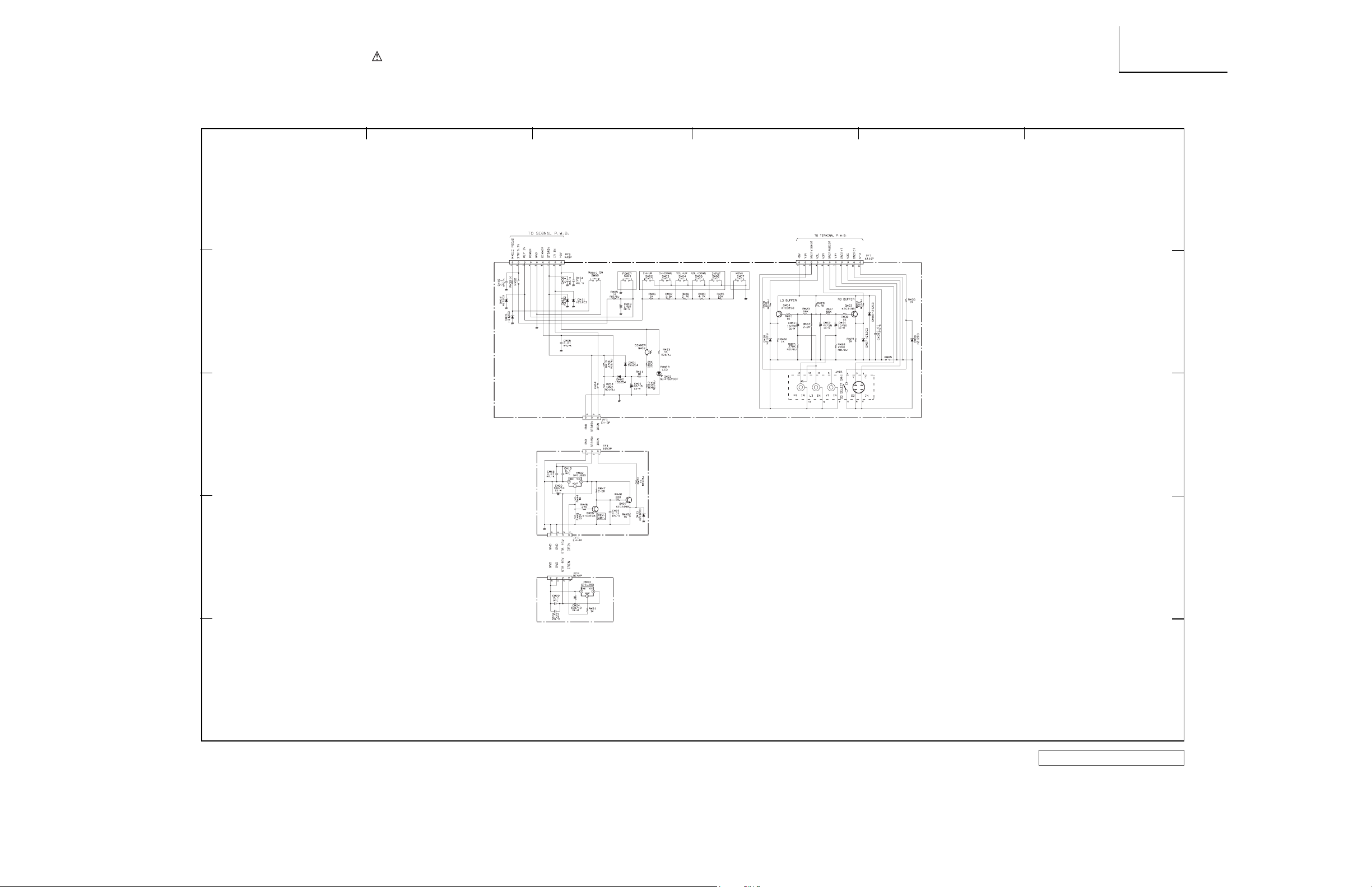
1 234
5
6
A
B
C
D
E
All DC voltage to be measured with a tester (100k/V). Voltage taken on a complex color bar signal including a standard color bar signal.
Since this is a basic circuit diagram, the value of the parts is subject to be altered for improvement.
CONTROL
PRODUCT SAFETY NOTE: Components marked with a and shaded have special characteristics important to
safety. Before replacing any of these components, read carefully the PRODUCT SAFETY NOTICE of this Service
Manual. Don’t degrade the safety of the receiver through improper servicing.
BASIC CIRCUIT DIAGRAM
DP27/D
CONTROL
94
Page 95

1 234
5
6
A
B
C
D
E
All DC voltage to be measured with a tester (100k/V). Voltage taken on a complex color bar signal including a standard color bar signal.
Since this is a basic circuit diagram, the value of the parts is subject to be altered for improvement.
DVI
PRODUCT SAFETY NOTE: Components marked with a and shaded have special characteristics important to
safety. Before replacing any of these components, read carefully the PRODUCT SAFETY NOTICE of this Service
Manual. Don’t degrade the safety of the receiver through improper servicing.
BASIC CIRCUIT DIAGRAM
DP27/D
DVI
95
Page 96

PRINTED CIRCUIT BOARD
SIGNAL P.W.B. - PART SIDE
96
DP27/27D
Page 97

DP27/27D
PRINTED CIRCUIT BOARD
SIGNAL P.W.B. - PATTERN SIDE
97
Page 98

PRINTED CIRCUIT BOARD
TERMINAL P.W.B. - PART SIDE
98
DP27/27D
Page 99

PRINTED CIRCUIT BOARD
TERMINAL P.W.B. - PATTERN SIDE
99
DP27/27D
Page 100

DP27/27D
PRINTED CIRCUIT BOARD
DEFLECTION P.W.B. - PART SIDE
100
 Loading...