

Models 27MM20BA and 27MMV30B are in the same Solid State Color Television family. The
difference between the 27MM20BA and the 27MMV30B is the DDC2B and instruction Book.
Please refer to Model 27MM20B and 27MM20BA schematics, assembly, wiring, test, and
troubleshooting information when servicing Model 27MMV30B. Refer to Service Manual PA No.
0092 issued in March 1998. Refer to Service Manual PA No. 0092 for the technical information
regarding the “Description of Circuit” and “IC’s and Transistors Functions” issued in March 1998.
REPLACEMENT PARTS LIST
This parts list only gives parts which are different from the Service Manual PA No. 0092.
PRODUCT SAFETY NOTE: Components marked with aA have special characteristics important
to safety. Before replacing any of these components, read carefully, the PRODUCT SAFETY
NOTICE of this Service Manual. Do not degrade the safety of the receiver through improper
servicing.
For 27MMV30B (Same as 27MM20BA except below parts)
SYMBOL
NO.
N201
B
Above parts list of 27MMV30B plus attached replacement parts
list are parts which are different from the Service Manual PA
No. 0092.
PART
NO.
QR26891
JK03655(H)
DESCRIPTION
Instruction Book English
PA2 DDC2B P.W.B.
SPECIFICATIONS AND PARTS ARE SUBJECTTO CHANGE FOR IMPROVEMENT
SOLID STATE COLOR TELEVISION
JULY 1998
HHEA-MANUFACTURING DIVISION
PA2
SAFETY PRECAUTIONS
NOTICE: Comply with all cautions and safety-related notes
located on or inside the cabinet and on the chassis or
picture tube.
WARNING: Since the chassis of this receiver is connected
to one side of the AC power supply during operation,
whenever the receiver is plugged in, service should not be
attempted by anyone unfamiliar with the precautions
necessary when working on this type of receiver.
The following precautions should be observed:
1. Do not install, remove, or handle the picture tube in any
manner unless shatterproof goggles are worn. People
not so equipped should be kept away from the picture
tube while handling.
2. When service is required, an isolation transformer
should be inserted between power line and the receiver
before any service is performed on a “HOT” chassis
receiver.
3. When replacing a chassis in the receiver, all the
protective devices must be put back in place, such as
barriers,
nonmetallic knobs, adjustment and
compartment cover-shields, isolation resistors,
capacitors, etc.
4. When service is required, observe the original lead
dress in the high voltage circuitry area.
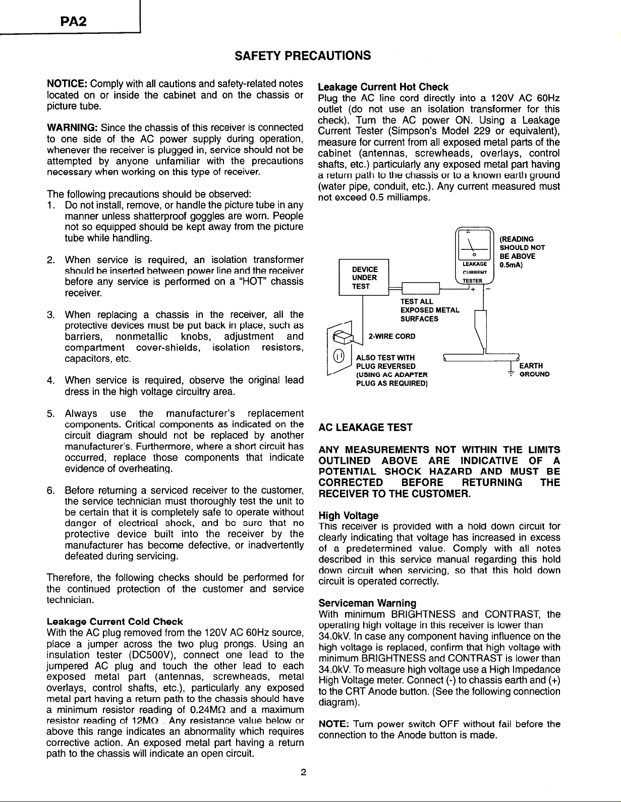
Leakage Current Hot Check
Plug the AC line cord directly into a 120V AC 60Hz
outlet (do not use an isolation transformer for this
check). Turn the AC power ON. Using a Leakage
Current Tester (Simpson’s Model 229 or equivalent),
measure for current from all exposed metal parts of the
cabinet (antennas, screwheads, overlays, control
shafts, etc.) particularly any exposed metal part having
a return path to the chassis or to a known earth ground
(water pipe, conduit, etc.). Any current measured must
not exceed 0.5 milliamps.
(READING
SHOULD NOT
BE ABOVE
0.5mA)
DEVICE
UNDER
TEST
TEST ALL
EXPOSED METAL
SURFACES
2-WIRE CORD
fUSlNG AC ADAPTER
PLUG AS REQUIRED)
LEAKAGE
CURRENT
<TESTER /
1
5. Always use
the manufacturer’s replacement
components. Critical components as indicated on the
circuit diagram should not be replaced by another
manufacturer’s Furthermore, where a short circuit has
occurred, replace those components that indicate
evidence of overheating.
6. Before returning a serviced receiver to the customer,
the service technician must thoroughly test the unit to
be certain that it is completely safe to operate without
danger of electrical shock, and be sure that no
protective device built into the receiver by the
manufacturer has become defective, or inadvertently
defeated during servicing.
Therefore, the following checks should be performed for
the continued protection of the customer and service
technician.
Leakage Current Cold Check
With the AC plug removed from the 12OV AC 60Hz source,
place a jumper across the two plug prongs. Using an
insulation tester (DC500V), connect one lead to the
jumpered AC plug and touch the other lead to each
exposed metal part (antennas, screwheads, metal
overlays, control shafts, etc.), particularly any exposed
metal part having a return path to the chassis should have
a minimum resistor reading of 0.24MQ and a maximum
resistor reading of 12MR . Any resistance value below or
above this range indicates an abnormality which requires
corrective action. An exposed metal part having a return
path to the chassis will indicate an open circuit.
AC LEAKAGE TEST
ANY MEASUREMENTS NOT WITHIN THE LIMITS
OUTLINED ABOVE ARE INDICATIVE OF A
POTENTIAL SHOCK HAZARD AND MUST BE
CORRECTED BEFORE
RETURNING THE
RECEIVER TO THE CUSTOMER.
High Voltage
This receiver is provided with a hold down circuit for
clearly indicating that voltage has increased in excess
of a predetermined value. Comply with all notes
described in this service manual regarding this hold
down circuit when servicing, so that this hold down
circuit is operated correctly.
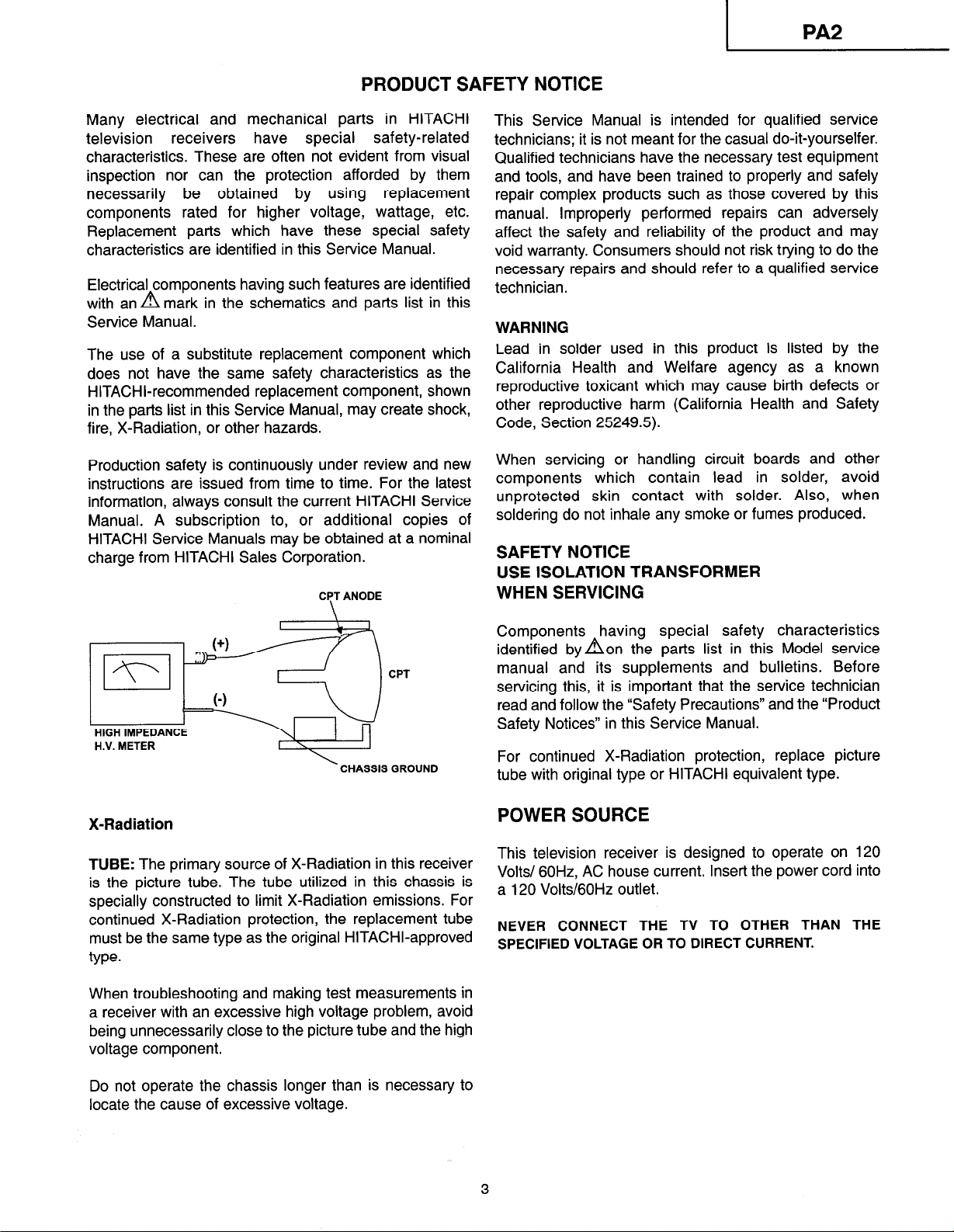
Serviceman Warning
With minimum BRIGHTNESS and CONTRAST, the
operating high voltage in this receiver is lower than
34.0kV. In case any component having influence on the
high voltage is replaced, confirm that high voltage with
minimum BRIGHTNESS and CONTRAST is lower than
34.0kV. To measure high voltage use a High Impedance
High Voltage meter. Connect (-) to chassis earth and (+)
to the CRT Anode button. (See the following connection
diagram).
NOTE: Turn power switch OFF without fail before the
connection to the Anode button is made.
2
I
PRODUCT SAFETY NOTICE
?A2
Many electrical and mechanical parts in HITACHI
television receivers have special safety-related
characteristics. These are often not evident from visual
inspection nor can the protection afforded by them
necessarily be obtained by using replacement
components rated for higher voltage, wattage, etc.
Replacement parts which have these special safety
characteristics are identified in this Service Manual.
Electrical components having such features are identified
with an a mark in the schematics and parts list in this
Service Manual.
The use of a substitute replacement component which
does not have the same safety characteristics as the
HITACHI-recommended replacement component, shown
in the parts list in this Service Manual, may create shock,
fire, X-Radiation, or other hazards.
Production safety is continuously under review and new
instructions are issued from time to time. For the latest
information, always consult the current HITACHI Service
Manual. A subscription to, or additional copies of
HITACHI Service Manuals may be obtained at a nominal
charge from HITACHI Sales Corporation.
CPT ANODE
\
CPT
This Service Manual is intended for qualified service
technicians; it is not meant for the casual do-it-yourselfer.
Qualified technicians have the necessary test equipment
and tools, and have been trained to properly and safely
repair complex products such as those covered by this
manual. Improperly performed repairs can adversely
affect the safety and reliability of the product and may
void warranty. Consumers should not risk trying to do the
necessary repairs and should refer to a qualified service
technician.
WARNING
Lead in solder used in this product is listed by the
California Health and Welfare agency as a known
reproductive toxicant which may cause birth defects or
other reproductive harm (California Health and Safety
Code, Section 25249.5).
When servicing or handling circuit boards and other
components which contain lead in solder, avoid
unprotected skin contact with solder. Also, when
soldering do not inhale any smoke or fumes produced.
SAFETY NOTICE
USE ISOLATION TRANSFORMER
WHEN SERVICING
Components having special safety characteristics
identified by aon the parts list in this Model service
manual and its supplements and bulletins. Before
servicing this, it is important that the service technician
read and follow the “Safety Precautions” and the “Product
Safety Notices” in this Service Manual.
\
CHASSIS GROUND
X-Radiation
TUBE: The primary source of X-Radiation in this receiver
is the picture tube. The tube utilized in this chassis is
specially constructed to limit X-Radiation emissions. For
continued X-Radiation protection, the replacement tube
must be the same type as the original HITACHI-approved
type.
When troubleshooting and making test measurements in
a receiver with an excessive high voltage problem, avoid
being unnecessarily close to the picture tube and the high
voltage component.
Do not operate the chassis longer than is necessary to
locate the cause of excessive voltage.
For continued X-Radiation protection, replace picture
tube with original type or HITACHI equivalent type.
POWER SOURCE
This television receiver is designed to operate on 120
Volts/ 60H2, AC house current. Insert the power cord into
a 120 Volts/GOHz outlet.
NEVER CONNECT THE TV TO OTHER THAN THE
SPECIFIED VOLTAGE OR TO DIRECT CURRENT.
3
TECHNICAL SPECIFICATIONS
PICTURE TUBE
27MMV30B/PA2 . . . . . . . . . . . . . . . . .A68KSA30X(D)
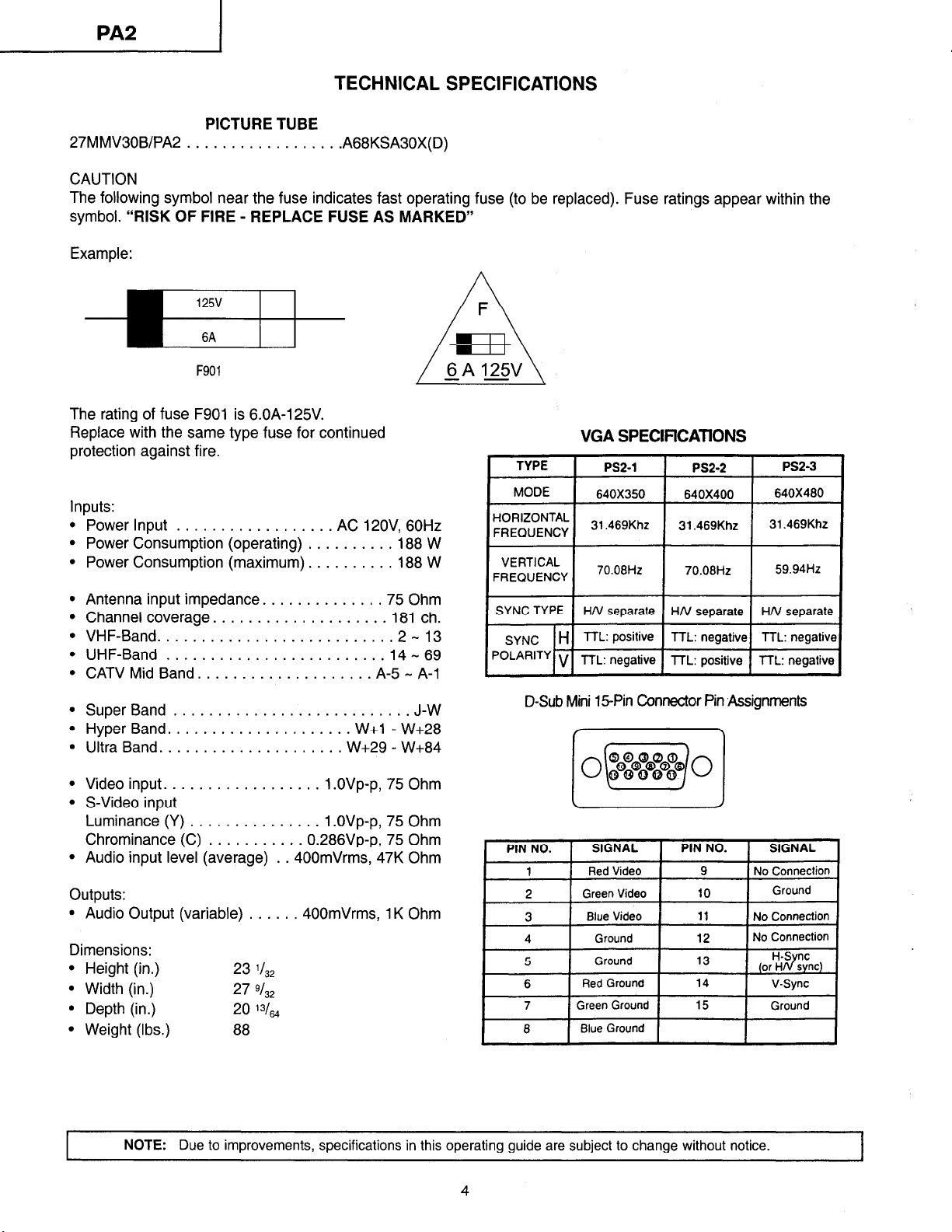
CAUTION
The following symbol near the fuse indicates fast operating fuse (to be replaced). Fuse ratings appear within the
symbol. “RISK OF FIRE - REPLACE FUSE AS MARKED”
Example:
F901
The rating of fuse F901 is 6.OA-125V.
Replace with the same type fuse for continued
protection against fire.
Inputs:
l
Power Input .................. AC 12OV, 60Hz
l
Power Consumption (operating) .......... 188 W
l
Power Consumption (maximum). ......... 188 W
. Antenna input impedance. ............ .75 Ohm
l
Channel coverage. ................... 181 ch.
l
VHF-Band .......................... .2- 13
l
UHF-Band ......................... 14 - 69
l
CATV Mid Band. ................... A-5 - A-l
l
Super Band ........................... J-W
l
Hyper Band. .................... W+l - W+28
l
Ultra Band. .................... W+29 - W+84
. Video input. ................. 1 .OVp-p, 75 Ohm
l
S-Video input
Luminance (Y) ............... 1 .OVp-p, 75 Ohm
Chrominance (C) ........... 0.286Vp-p, 75 Ohm
l
Audio input level (average) . .400mVrms, 47K Ohm
outputs:
l
Audio Output (variable) ...... 400mVrms, 1K Ohm
Dimensions:
l
Height (in.)
l
Width (in.)
l
Depth (in.)
l
Weight (Ibs.)
23 ‘l32
27 9/32
20
‘3/64
88
--
VGA SPECIFICATONS
1 TYPE 1
MODE
HORIZONTAL
FREQUENCY
1 F;E;;&y 1 70.06Hz 1 70.06Hz 1 59.94Hz 1
SYNC TYPE
SYNC H TTL: positive TTL: negative TTL: negative
PoLAR’TY V TTL: negative TTL: positive TTL: negative
I
D-Sub Mini 15Pin Connector Pin ,Assignments
PIN NO. SIGNAL PIN NO. SIGNAL
1 Red Video 9 No Connection
2 Green Video
3 Blue Video 11 No Connection
4 Ground 12 No Connection
5
6
7
8
PS2-1 1 Ps2-2 1 PS2-3 i
640X350 640X400
31.469Khz
31.469Khz
HN separate HN separate HN separate
10
Ground 13
Red Ground 14 V-Sync
Green Ground 15
Blue Ground
640X480
31.469Khz
Ground
H-S nc
(or Hd sync)
Ground
NOTE:
Due to improvements, specifications in this operating guide are subject to change without notice.
4
I
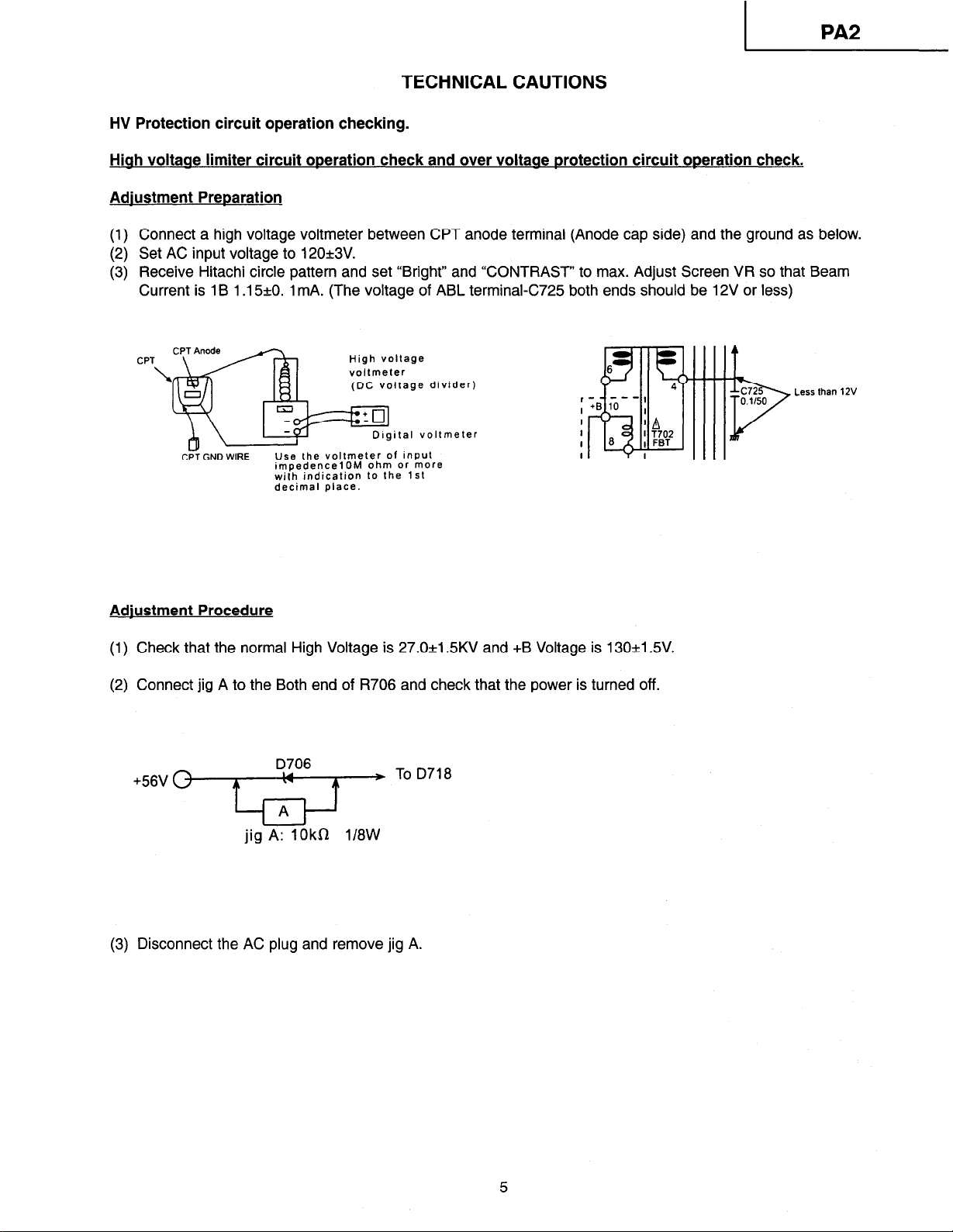
TECHNICAL CAUTIONS
HV Protection circuit operation checking.
Hiah voltaae limiter circuit operation check and over voltaae protection circuit operation check.
Adjustment Preparation
(1) Connect a high voltage voltmeter between CPT anode terminal (Anode cap side) and the ground as below.
(2) Set AC input voltage to 120&3V.
(3) Receive Hitachi circle pattern and set “Bright” and “CONTRAST” to max. Adjust Screen VR so that Beam
Current is 1 B 1 .15&O. 1 mA. (The voltage of ABL terminal-C725 both ends should be 12V or less)
CPT
\
GND WIRE
Adiustment Procedure
(1) Check that the normal High Voltage is 27.0+1.5KV and +B Voltage is 130+1.5V.
(2) Connect jig A to the Both end of R706 and check that the power is turned off.
+56V 0-w To D718
Use the voltmeter Of input
impedencelOM ohm or more
with indication to the 1st
decimal place.
D706
High voltage
voltmeter
(DC voltage divider)
ital voltmeter
c725
0.1150
Less than 12V
3
w
4-s-J
jig=kR 1/8W
(3) Disconnect the AC plug and remove jig A.
1 /XN&S;‘ELATORY 1
Federal Communications Commission Notice
This equipment has been tested and found to comply with the limits for a Class B digital device,
pursuant to Part 15 of the FCC Rules. These limits are designed to provide reasonable protection against harmful
interference in a residential installation. This equipment generates, uses, and can radiate radio frequency energy
and, if not installed and used in accordance with the instructions, may cause harmful interference to radio
communications. However, there is no guarantee that interference will not occur in a particular installation. If this
equipment does cause harmful interference to radio or television reception, which can be determined by turning
the equipment off and on, the user is encouraged to try to correct the interference by one or more of the following
measures:
l
Reorient or relocate the receiving antenna.
l
Increase the separation between the equipment and the receiver.
l
Connect the equipment into an outlet on a circuit different from that to which the receiver is connected.
l
Consult the dealer or an experienced radio or television technician for help.
Modifications
The FCC requires the user to be notified that any changes or modifications made to this device that are not
expressly approved by Hitachi Home Electronics (America), Inc. may void the user’s authority to operate the
equipment.
Cables
Connections to this device must be made with shielded cables with metallic RFI/EMI connector hoods to maintain
compliance with FCC Rules and Regulations.
Any cables that are supplied with the system must be replaced with identical cables in order to assure compliance
with FCC rules. Order Hitachi spares as replacement cables.
Declaration of Conformity
This device complies with Part 15 of the FCC Rules. Operation is subject to the following two conditions: (1)
this device may not cause harmful interference, and (2) this device must accept any interference received,
including interference that may cause undesired operation.
Any cables that are supplied with the system must be replaced with identical cables in order to assure
compliance with FCC rules. Order Hitachi spares as replacement cables.
For questions regarding this declaration, contact:
Hitachi Home Electronics (America), Inc.
1855 Dornoch Court
San Diego, CA 92173
l-800-448-2244 (l -800-HITACHI)
Attn: Customer Relations

REPLACEMENT PARTS LIST
PRODUCT SAFETY NOTE: Components marked with aAhave special characters important to safety.
Before replacing any of these components, read carefully the PRODUCT SAFETY NOTICE of this service manual.
Don’t degrade the safety of the receiver through improper servicing.
ABBREVIATIONS
Capacitors:
CD: Ceramic Disc
PF: Polyester Film
EL: Electrolytic
PP: Polypropylene
PR: Paper
TA: Tantalum
TM: Trimmer
MC
Mvkr
SYMBOL
NO.
LJT0660
CYOI
CYO2
DYOl
DY02
DY03
IYOl
KY51
KY52
LYOI
PYOl
PYO2
RYOl
RY02
RY03
RY04
RY05
Resistor:
Carbon Film
CF:
Carbon Composition
cc:
MF: Metal Oxide Film
VR: Variable Resistor
WW: Wire Wound
FR: Fuse Resistor
MG: Metal Glaze
0880009R
0800039R CAP.-ELECTRO. 47UF-M 1OV
2339856M ZENER HZS7B3 TA
2339856M ZENER HZS7B3 TA
2339856M
CPOlO42U DIGITAL MONOLITHIC IC (24LC21AJP)
2974432M
2974432M
BH00697R COIL 1OOUH
2959051
0100041 M
0100041 M
0100041 M
0700063M
0700063M
Semiconductors:
TR: Transistor
DI: Diode
ZD: Zener Diode
VA: Varistor
TH: Thermistor
IC: Integrated Circuit
PART
DESCRIPTION
DDCPB P.W.B.
CAP.-POLYESTER 0.01 UF-K 50V
ZENER HZS783 TA
JUMPER WIRE (0.5 L=52MM)
JUMPER WIRE (0.5 L=52MM)
5P POST PIN 4P TYPE PH
PIN POST (PH 2P)
RES.-CARBON FLM 1/8W 1 00-JB
RES.-CARBON FLM 1/8W 1 00-JB
RES.-CARBON FLM 1/8W 1 00-JB
RES.-CARBON FLM 1/16W 47K-JB
RES.-CARBON FLM 1/16W 47K-JB
7

lpyoll
GND
Data
CLK
X-Sync
BASIC CIRCUIT DIAGRAM
DDC2B Circuit Schematic
lpvoll
+5v
+5v
I
a’ -
2
HZS7B3
-lhl
DYOI DY02
HZS7B3 HZS783 HZS7B3
nil nh
LYOI
100
DY03
-vv--
-..__ .__ ~o,,BJ
“103 I”“,
PA2 CHASSIS BLOCK DIAGRAM
I
RYOS
47K
I
II
PRODUCT SAFETY NOTE: Components marked with a A and shaded have special characteristics important to
safety. Before replacing any of these components, read carrefully the PRODUCT SAFETY NOTICE of this Service
Manual. Don’t degrade the safety of the receiver through improper servicing.
l
All DC voltage to be measured with a tester (100kWV). Voltage taken on a complex color bar signal including
a standard color bar signal.
l
Since this is a basic circuit diagram, the value of the parts is subject to be altered for improvement.
8


NOTES:

HITACHI
 Loading...