

Hitachi NT 65M2, NT 65M2 S User Manual
11-(6)
Switching
Device
Downward position
11-(4)
Switching
Device
Pull Trigger
Upward position
11-(1)
Do not
connect
air hose
Trigger
Push
Lever
Exhaust Cover
Bolt
10
11-(2)(3)
Do not pull
Trigger
Depress
Push Lever
Switching
Device
Upward position
9
Head Valve
Spring
Head
Valve
Piston
Cylinder
Head
Bamper
Cylinder
Plate
2
1
Allen Wrench For
M5 Screw
O-Ring Pick
Bolt
Exhaust Cover
4
Cylinder
Piston
6
Head Valve
Exhaust
Cover
7
O-Ring Pick
Old O-Ring
8
Body
Cylinder Plate
Head
Valve
Exhaust
Cover
Cylinder
3
5
For air leakage or sluggish operation.
FOR USE BY ONLY SERVICE PERSONNEL TRAINED
BY HITACHI, DISTRIBUTOR OR EMPLOYER.
FINISH NAILER
MODEL NT 65M2 / NT 65M2 (S)
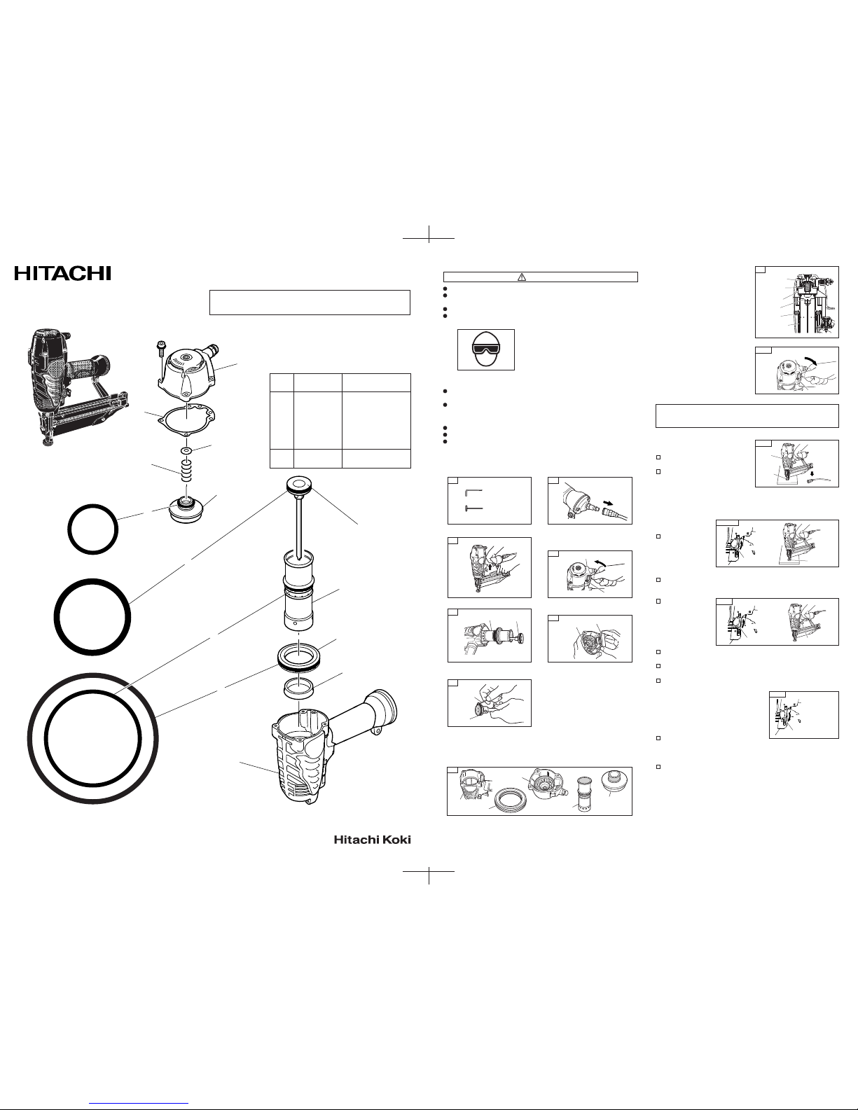
Item
No.
1 885-672 Gasket
2 883-992 O-Ring
3 885-668 O-Ring
4 880-362 O-Ring
5 885-665 O-Ring
6 885-666 Cylinder Ring
O-Ring Pick
Tube Grease
Code No. Part Name
O-Ring Shown Actual Size
GENUINE PARTS
Body
6
Cylinder Plate
Cylinder
Piston
Exhaust Cover
Head Valve Spring
Head Valve
1
Head Bumper
2
3
5
4
Kit-
READ AND UNDERSTAND THIS MANUAL BEFORE DOING REPAIRS.
Only service personnel trained by Hitachi, distributor or employer shall
repair the Nailer.
Use only parts supplied or recommended by Hitachi for repair.
Before doing repairs,
1)WEAR SAFETY GLASSES;
2)DISCONNECT AIR HOSE FROM NAILER; and
3)REMOVE ALL NAILS FROM NAILER.
After doing repairs,
TEST NAILER PER ITEM No. 11 OF THIS MANUAL BEFORE USE.
If you have any questions regarding repair, use or safety warnings, call a
Hitachi authorized service center.
CAUTION ON REPAIR
Oily or greasy hands can slip easily.
Do not allow dust or foreign matter to enter Nailer.
Do not scratch the O-rings or O-ring contacting surface of any parts.
This will cause air leakage from Nailer.
DANGER
Pay attention not to scratch exhaust
cover and body when remove old
gasket.
Install new o-rings and cylinder ring as
shown right.
Install cylinder and piston into body.
Make sure that head bumper, head
valve spring and o-ring are properly
placed in head valve.
Install head valve into exhaust cover.
9.
8.
Wipe body, exhaust cover, head valve, cylinder plate and cylinder with
clean cloth.
Put an adequate amount of grease on shaded area of body, exhaust cover,
head valve, cylinder plate and cylinder. Put an adequate amount of grease on
new o-rings and cylinder ring.
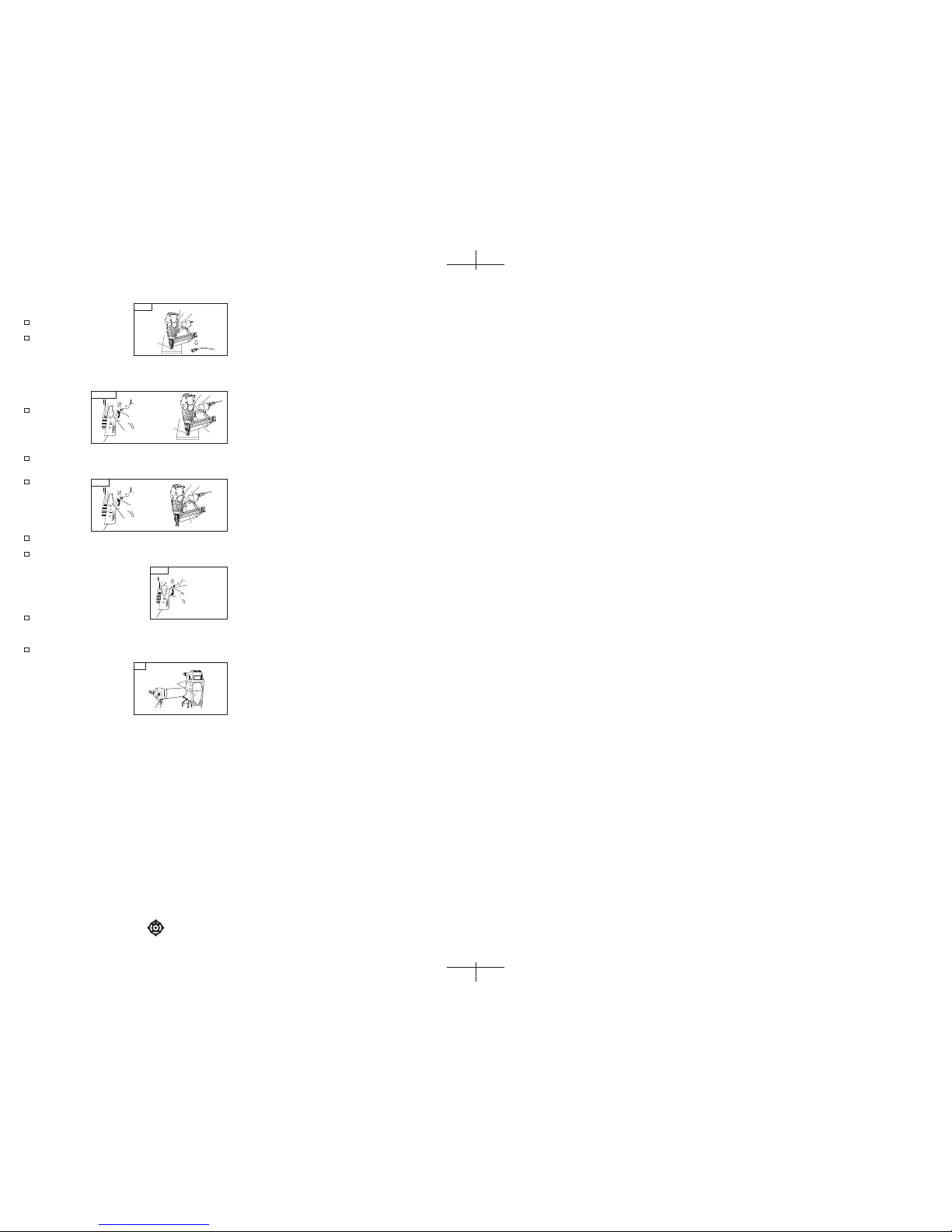
[MODEL NT65M2]
(1) DISCONNECT AIR HOSE FROM NAILER.
REMOVE ALL NAILS FROM NAILER.
ALL SCREWS MUST BE TIGHTENED.
If any screws are loose, tighten them.
THE PUSH LEVER AND TRIGGER
MUST MOVE SMOOTHLY.
(2) Adjust the air pressure to 70 psi. (4.9 bar 5 kgf/cm2). Connect the air hose.
Do not load any nails in the Nailer. Set the switching device to the upward
position (SINGLE SEQUENTIAL ACTUATION MECHANISM). (Set the
switching device to the upward position completely as shown in the diagram.
Otherwise, it will not
operate properly.)
THE NAILER MUST
NOT LEAK AIR.
(3) Remove the finger from
the trigger and press
the push lever against
the wood.
THE NAILER MUST NOT OPERATE.
(4) Separate the push lever from the wood. Next, point the nailer downward, pull
the trigger and then wait in that position for 5 seconds or longer.
THE NAILER MUST
NOT OPERATE.
(5) 1Without touching the
trigger, depress the
push lever against the
workpiece.
Pull the trigger.
THE NAILER MUST OPERATE.
2Hold the trigger back while separating the push lever from the wood.
The nailer will remain in operated status (the driver blade will remain at
the bottom). 3Remove the finger from the trigger.
Nailer operation will end (the driver blade will return to the top).
(6) Set the switching device to the downward position (CONTACT ACTUATION
MECHANISM). (Set the switching device to
the downward position completely as shown
in the diagram. Otherwise, it will not operate
properly.)
With the Nailer off the workpiece, pull the trigger.
Depress the push lever against the workpiece.
THE NAILER MUST OPERATE.
(7) If no abnormal operation is observed, you may load nails in the Nailer.
Drive nails into the workpiece that is the same type to be used in the actual
application.
THE NAILER MUST OPERATE
PROPERLY.
IMPORTANT SAFETY INSTRUCTIONS
HOW TO REPAIR
Install new gasket, exhaust cover and
four bolts. Using Allen wrench for M5
screw, tighten four bolts in a staggered
sequence.
10.
7.
Using o-ring pick, remove old o-rings.
Discard old o-rings.
6.
Remove head valve from exhaust
cover .
5.
Remove piston and cylinder.
3.
Remove all nails from the Nailer.
1.
The tools needed for repair are shown
below.
2.
Disconnect the air hose from the
Nailer.
4.
Using Allen wrench for M5 screw,
remove four bolts from exhaust cover.
Remove exhaust cover.
11. When reassembled, always conduct following tests in the following order.
If abnormal operation occurs, stop using the Nailer and contact a Hitachi
authorized service center immediately.
11-(6)
Switching
Device
11-(4)
11-(1)
Do not
connect
air hose
Trigger
Push
Lever
11-(2)(3)
Do not pull
Trigger
Depress
Push
Lever
Switching
Device
Upward position
Switching
Device
Upward position
Pull Trigger
Downward position
Warning
Label
12
Printed in Taiwan
Code No. C99520212
206
Hitachi Koki Co., Ltd.
Printed in Taiwan
Code No. C99520212
206
Hitachi Koki Co., Ltd.
[MODEL NT65M2 (S)]
(1) DISCONNECT AIR HOSE FROM NAILER.
REMOVE ALL NAILS FROM NAILER.
ALL SCREWS MUST BE TIGHTENED.
If any screws are loose, tighten them.
THE PUSH LEVER AND TRIGGER
MUST MOVE SMOOTHLY.
(2) Adjust the air pressure to 70 psi. (4.9 bar 5 kgf/cm2). Connect the air hose.
Do not load any nails in the Nailer. Set the switching device to the upward
position (SINGLE SEQUENTIAL ACTUATION MECHANISM). (Set the
switching device to the upward position completely as shown in the diagram.
Otherwise, it will not
operate properly.)
THE NAILER MUST
NOT LEAK AIR.
(3) Remove the finger from
the trigger and press
the push lever against
the wood.
THE NAILER MUST NOT OPERATE.
(4) Separate the push lever from the wood. Next, point the nailer downward, pull
the trigger and then wait in that position for 5 seconds or longer.
THE NAILER MUST
NOT OPERATE.
(5) 1Without touching the
trigger, depress the
push lever against the
workpiece.
Pull the trigger.
THE NAILER MUST OPERATE.
2Removethe finger from the trigger.
Nailer operation will end (the driver blade will return to the top).
(6) Set the switching device to the downward position (CONTACT ACTUATION
MECHANISM). (Set the switching device to
the downward position completely as shown
in the diagram. Otherwise, it will not operate
properly.)
With the Nailer off the workpiece, pull the trigger.
Depress the push lever against the workpiece.
THE NAILER MUST OPERATE.
(7) If no abnormal operation is observed, you may load nails in the Nailer.
Drive nails into the workpiece that is the same type to be used in the actual
application.
THE NAILER MUST OPERATE
PROPERLY.
12.Change the WARNING LABEL if missing
or damaged.
A new WARNING LABEL is available from
a Hitachi authorized service center.
 Loading...