

Hitachi NT 65A3 Technical Data And Service Manual

TECHNICAL DATA
AND
SERVICE MANUAL
FINISH NAILER
NT 65A3
SPECIFICATIONS AND PARTS ARE SUBJECT TO CHANGE FOR IMPROVEMENT
LIST No. E012 Aug. 2003
N
MODEL
NT 65A3
Hitachi
Power Tools

REMARK:
Throughout this TECHNICAL DATA AND SERVICE MANUAL, a symbol(s)
is(are) used in the place of company name(s) and model name(s) of our
competitor(s). The symbol(s) utilized here is(are) as follows:
Symbols Utilized
Competitors
Company Name
Model Name
DEWALT
D51256K
S

CONTENTS
Page
1. PRODUCT NAME...........................................................................................................................1
2. MARKETING OBJECTIVE .............................................................................................................1
3. APPLICA TIONS..............................................................................................................................1
4. SELLING POINTS ..........................................................................................................................1
5. SPECIFICATIONS ..........................................................................................................................2
5-1. Specifications................................................................................................................................. 2
5-2. Nail Selection................................................................................................................................. 2
5-3. Explanation of the Nailing Operation ............................................................................................. 3
5-4. Nail Driving Force .......................................................................................................................... 4
5-5. Optional Accessory: Full Sequential Actuation Mechanism Kit
(Sequential Trip Mechanism Kit)................................................................................................... 5
6. COMPARISONS WITH SIMILAR PRODUCTS..............................................................................5
7. PRECAUTIONS IN SALES PROMOTION .....................................................................................6
7-1. Handling Instructions ..................................................................................................................... 6
7-2. Warning Label................................................................................................................................ 6
7-3. Related Laws and Regulations ...................................................................................................... 7
8. MECHANISM AND OPERATION PRINCIPLE ...............................................................................8
8-1. Mechanism .................................................................................................................................... 8
8-2. Interchangeability......................................................................................................................... 10
8-3. Operation Principle ...................................................................................................................... 14
9. TROUBLESHOOTING GUIDE .....................................................................................................20
9-1. Troubleshooting and Correction................................................................................................... 20
9-2. Possible Causes and Countermeasures for Air Leakage ............................................................ 23
10. DISASSEMBLY AND REASSEMBLY ........................................................................................25
10-1. General Precautions in Disassembly and Reassembly ............................................................. 25
10-2. Disassembly and Reassembly of the Output Section................................................................ 26
10-3. Disassembly and Reassembly of the Control Valve Section ..................................................... 30
10-4. Disassembly and Reassembly of the Magazine Section and the Driving Section..................... 32
11. INSPECTION AND CONFIRMATION AFTER REASSEMBLY ..................................................36
12. STANDARD REPAIR TIME (UNIT) SCHEDULES .....................................................................37
Assembly Diagram for NT 65A3

--- 1 ---
1. PRODUCT NAME
Hitachi Finish Nailer, Model NT 65A3
2. MARKETING OBJECTIVE
The new Model NT 65A3 finish nailer is a minor-changed version of the current Model NT 65A2. To correspond to
the modification of the ANSI standard on the 1st of May 2003, the valve construction was partially changed.
In addition, the switching device (valve sleeve (A)) was provided to make the nailer operation selectable between
"single actuation (single sequential actuation) mechanism" and "contact actuation mechanism" (the current Model
NT 65A2 is provided with the contact actuation mechanism only). The grip tape wound around the handle of the
body was changed to the grip rubber that is common to the Model NR 83A2. The new Model NT 65A3 has the
same construction as the current Model NT 65A2 including the well-reputed tool-less clogged nail release
mechanism, driving force, response and balance.
3. APPLICA TIONS
Finish-nailing of door casings, window casings and similar frame assemblies.
Fastening of drawer bottoms and similar assembly work in the construction of various cabinets and cases.
4. SELLING POINTS
Rapid driving and
quick response
Equipped with a rubber grip
With "single actuation/
contact actuation" selector
--- 2 ---
Optional accessories
Loadable number of nails
2.0 kg (4.4 lbs.)
Corrugated cardboard box
3 nails/sec.
Driving speed
380 mm x 254 mm x 76 mm (14-31/32" x 10" x 3")
150 nails
Dimensions (L x H x W)
Nail feed system
Standard accessories
Product weight
Ribbon spring
Package dimensions (L x H x W)
Packaging
436 mm x 96 mm x 309 mm (17-5/32" x 3-25/32" x 12-5/32")
Safety glasses (Code No. 875769)........................................................... 1
Hex. bar wrench for M5 screw (Code No. 944458)
..................................
1
Nose cap (A) (Code No. 881751)
.............................................................
1
Full sequential actuation mechanism kit (Code No. 884178)
(Sequential trip mechanism kit)
Pneumatic tool lubricant (1 oz oil feeder) (Code No. 877153)
Pneumatic tool lubricant (4 oz oil feeder) (Code No. 872042)
Pneumatic tool lubricant (1 quart can) (Code No. 876212)
Grease (ATTOLUB No. 2) (500 g (1.1 lbs.)) (Code No. 317918)
Grease (MULTEMP PS No. 2) (30 g (0.07 lbs.)) (Code No. 939301)
5. SPECIFICATIONS
5-1. Specifications
Reciprocating piston type
Item
Driving system
NT 65A3
Applicable air pressure
5 --- 8.5 kgf/cm2 (gauge pressure) (70 to 120 psi)
5-2. Nail Selection
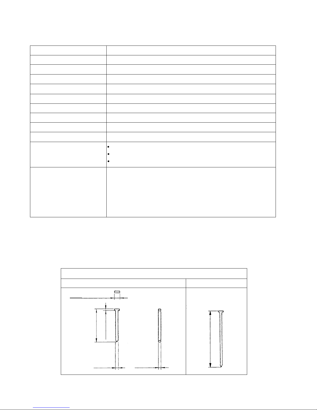
The Model NT 65A3 utilizes small-head, T-shaped nails (finish nails) collated by adhesive. Applicable nails are
shown below.
CAUTION: Ensure that nails are as specified in Fig. 1. Other nails will cause clogging of nails and
subsequent damage to the nailer.
2.8 mm (0.110")
1.4 mm
(0.054")
38 mm (1-1/2")
Minimum
16 gauge brad
Maximum
65 mm (2-1/2")
1.3 mm (0.050")
1.65 mm
(0.065")
Fig. 1 Dimensions of nails
--- 3 ---
(Valve sleeve (A))
(Valve sleeve (A))
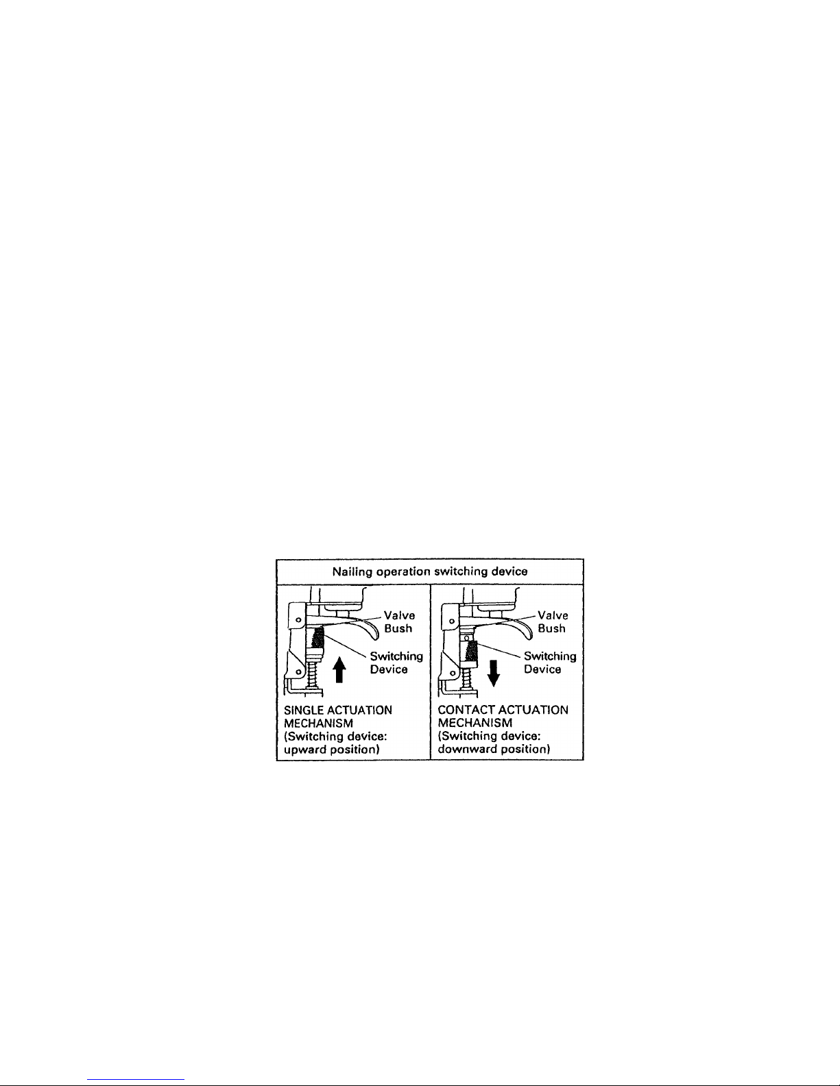
5-3. Explanation of the Nailing Operation
To meet the requirements of "ANSI SNT-101-2002", the Model NT 65A3 is equipped with a nailing operation
switching device at the valve portion as shown in the figures below. Use SINGLE ACTUATION MECHANISM
(SINGLE SEQUENTIAL ACTUATION MECHANISM) or CONTACT ACTUATION MECHANISM in accordance with
the work to be performed. A FULL SEQUENTIAL ACTUATION MECHANISM KIT (SEQUENTIAL TRIP
MECHANISM KIT) is also available as an option. Each nailing operation is as follows.
SINGLE ACTUATION MECHANISM (SINGLE SEQUENTIAL ACTUATION MECHANISM):
First, press the pushing lever against the wood; next, pull the trigger to drive the nail. First, pull the trigger; next,
press the pushing lever against the wood to drive the nail. After nailing once, nailing will not be possible again
until the trigger is released and pressed again.
CONT ACT ACTUA TION MECHANISM:
First, press the pushing lever against the wood; next, pull the trigger to drive the nail. First, pull the trigger; next,
press the pushing lever against the wood to drive the nail. If the trigger is held back, a nail will be driven each
time the pushing lever is pressed against the wood.
FULL SEQUENTIAL ACTUATION MECHANISM:
First, press the pushing lever against the wood; next, pull the trigger to drive the nail. Follow the same sequence
to continue driving nails.
--- 4 ---
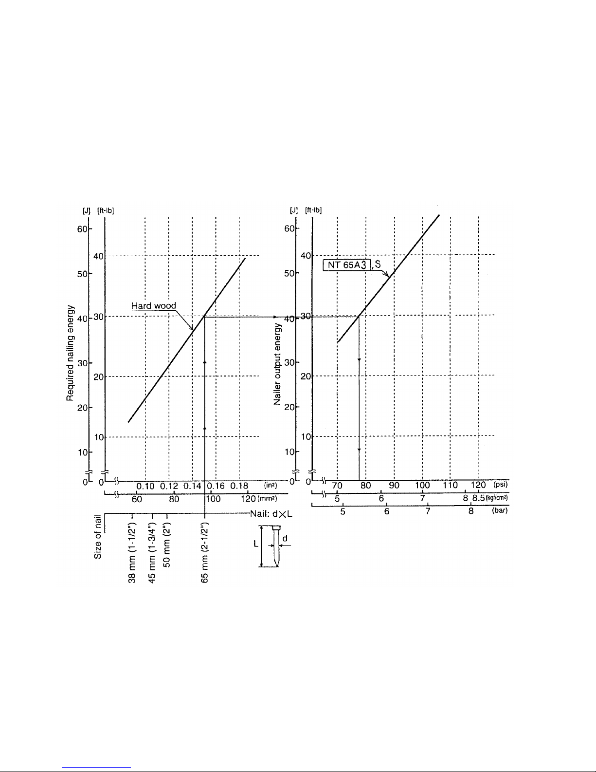
5-4. Nail Driving Force
Figure 2 shows the nailer output energy provided by the supply pressure and the required nailing energy for
driving the nail flush with surface of a workpiece with variables of types of wood and nails. Air pressure which
exceeds the intersecting point between the nailer output energy and the required nailing energy for driving the nail
allows the nail to be fully driven. For example, when driving a 65 mm (2-1/2") nail into a hard wood workpiece
with the Model NT 65A3, a pressure of about 5.5 kgf/cm2 (78 psi, 5.4 bar) allows the nailer to drive the nail flush
with the surface. A pressure beyond this value causes the nail head to be driven below the wood surface.
Figure 2 should be used as a reference only because those values vary depending on the type of wood, moisture
content and grain of wood.
Fig. 2 Required nailing energy and nailer output energy
Air pressure setting of NT 65A3 to drive nail flush
--- 5 ---
5-5. Optional Accessory: Full Sequential Actuation Mechanism Kit (Sequential Trip Mechanism Kit)
Full sequential actuation mechanism kit (sequential trip mechanism kit) (Code No. 884178) is provided as an
optional accessory for the Model NT 65A3. When using this optional accessory, a nail is driven when pressing the
pushing lever first against a workpiece and then pulling the trigger, and no nail is driven when pulling the trigger
first and then pressing the pushing lever against a workpiece (single-shot operation). Please recommend the
sequential fire parts set to customers who may want to use it. Salespersons must instruct the customers to read
the Instruction Manual attached to the sequential fire parts set and also the Handling Instructions of the Model
NT 65A3 thoroughly for correct use.
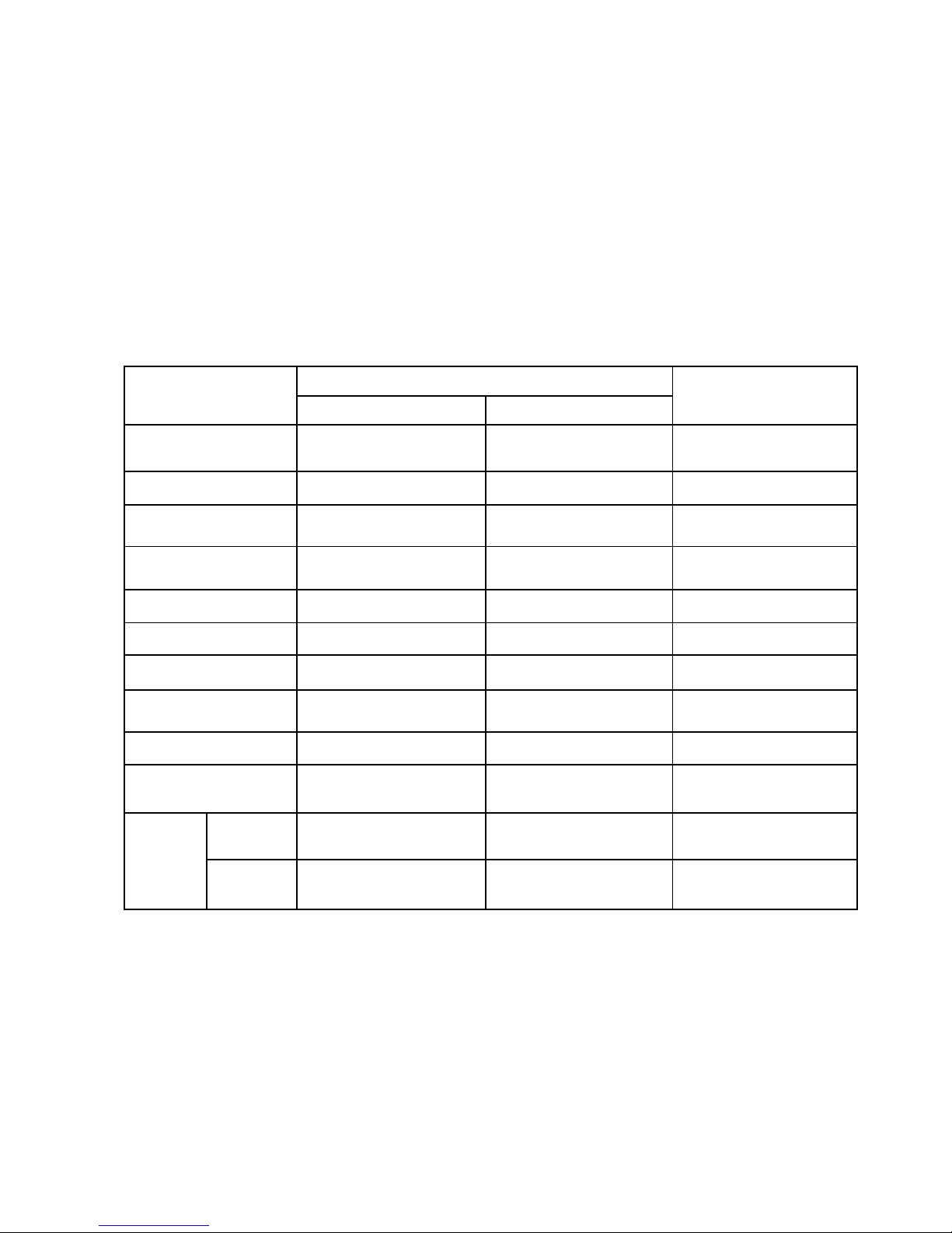
Maker, model
HITACHI
Air consumption at
7 kgf/cm2 (100 psi)
Operating pressure
Magazine type
Weight
Dimensions
(L x H x W)
Nail capacity
Driving depthadjustment mechanism
Handle grip
Applicable
nails
Length
Dia.
5 to 8.5 kgf/cm
2
(70 to 120 psi)
380 mm x 254 mm x 76 mm
(14-31/32" x 10" x 3")
NT 65A3
1.14 ltr/cycle
(0.042 ft3/cycle)
150 pcs.
Top loading
2.0 kg (4.4 lbs.)
None
Rubber
38 mm to 65 mm
(1-1/2" to 2-1/2")
1.4 mm to 1.65 mm (#16)
(0.054" to 0.065")
5 to 8.5 kgf/cm
2
(70 to 120 psi)
380 mm x 254 mm x 76 mm
(14-31/32" x 10" x 3")
NT 65A2
1.14 ltr/cycle
(0.042 ft3/cycle)
150 pcs.
Top loading
2.0 kg (4.4 lbs.)
None
Racket grip
38 mm to 65 mm
(1-1/2" to 2-1/2")
1.4 mm to 1.65 mm (#16)
(0.054" to 0.065")
5 to 8.5 kgf/cm
2
(70 to 120 psi)
318 mm x 241 mm x 76 mm
(12-1/2" x 9-1/2" x 3")
1.00 ltr/cycle
(0.035 ft3/cycle)
160 pcs.
Rear loading
1.9 kg (4.2 lbs.)
Tool less
Rubber
32 mm to 65 mm
(1-1/4" to 2-1/2")
1.4 mm to 1.65 mm (#16)
(0.054" to 0.065")
S
6. COMPARISONS WITH SIMILAR PRODUCTS
Jam cleaning mech.
Tool less
Tool less
Tool less
Single actuation/contact
actuation selector
Provided
None
None

--- 6 ---
7. PRECAUTIONS IN SALES PROMOTION
In the interest of promoting the safest and most efficient use of the Model NT 65A3 Nailer by all of our customers,
it is very important that at the time of sale, the salesperson carefully ensures that the buyer seriously recognizes
the importance of the contents of the Handling Instructions, and fully understands the meaning of the precautions
listed on the Warning Label attached to each tool.
7-1. Handling Instructions
Although every effort is made in each step of design, manufacture, and inspection to provide protection against
safety hazards, the dangers inherent in the use of any pneumatic tool cannot be completely eliminated.
Accordingly, general precautions and suggestions for the use of pneumatic tools, and specific precautions and
suggestions for the use of the pneumatic nailer are listed in the Handling Instructions to enhance the safe, efficient
use of the tool by the customer.
Salespersons must be thoroughly familiar with the contents of the Handling Instructions to be able to offer
appropriate guidance to the customers during sales promotion.
7-2. Warning Label
Each Model NT 65A3 unit is provided with a Warning Label (illustrated below) which lists basic safety precautions
in its use. Carefully ensure that the customers fully understand and follow these precautions before using the
tool.

--- 7 ---
7-3. Related Laws and Regulations
As nailers or staplers are designed to instantaneously drive nails or staples, there is an ever-present danger of
misfiring and subsequent possible serious injury. Accordingly, close attention in handling is absolutely necessary
at all times. Carefully ensure that the customer is fully aware of the precautions listed in the Handling Instructions
provided with each unit.
While there are no specific safety regulations, there are related items in various general safety regulations with
which the salespersons should be familiar in order to advise the customer properly. Please check your national
and/or local regulations for applicable items. Some applicable items are outlined below.
The U.S.A:
OSHA 1926.102 Eye and Face Protection
1926.302 Power-Operated Hand Tools
ANSI SNT-101-2002 Portable, Compressed-Air-Actuated,
Fastener Driving Tools-Safety Requirements for

--- 8 ---
8. MECHANISM AND OPERATION PRINCIPLE
8-1. Mechanism
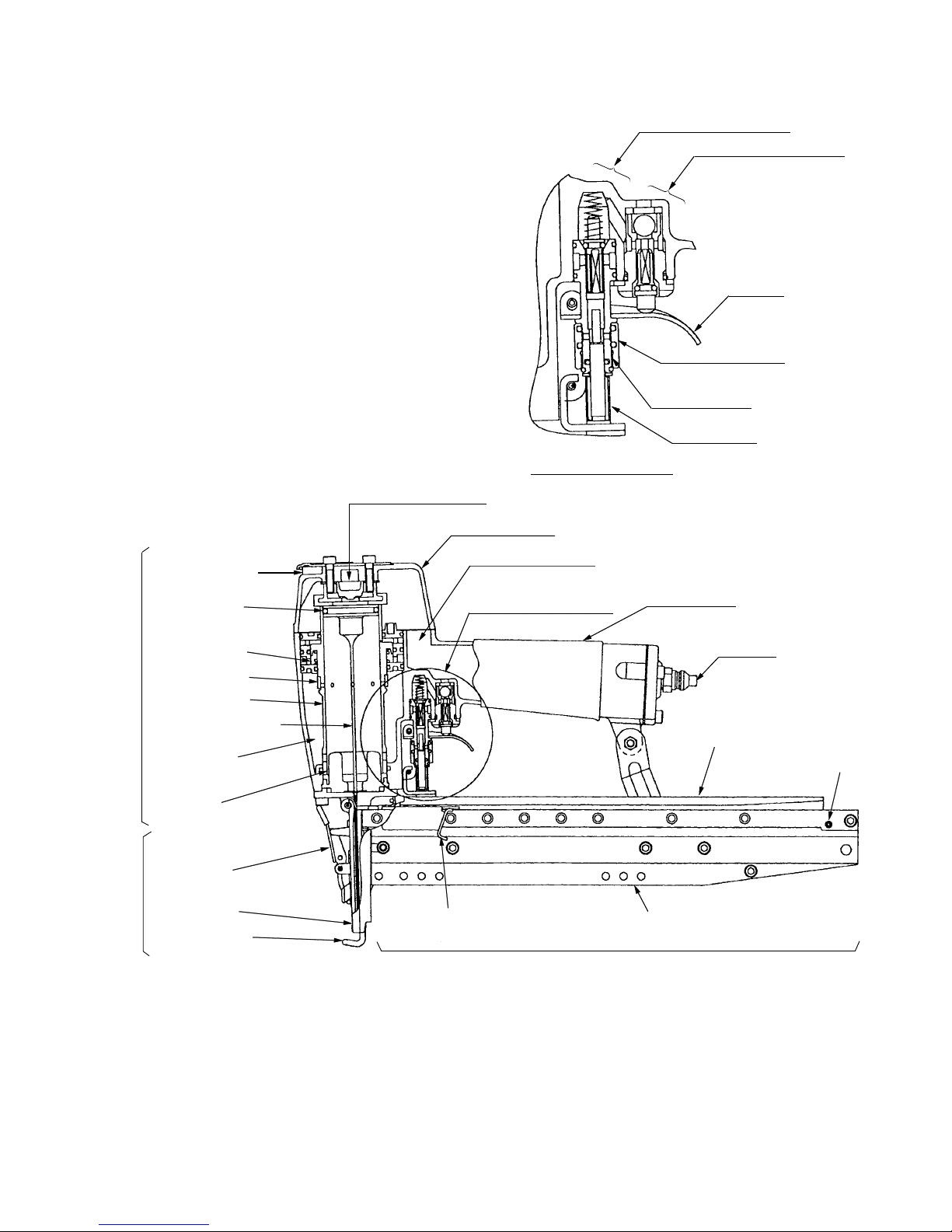
As illustrated in Fig. 3, the Model NT 65A3 can be generally divided into four sections:
output section, control valve section, driving section and magazine section.
The basic construction of the Model NT 65A3 is the same as that of the Model NT 65A2. The magazine section is
common to that of the Model NT 65A2. However, most of the parts of the control valve section were changed to
provide the single actuation (single sequential actuation)/contact actuation mechanisms in order to correspond to
the modification of the ANSI standard. The pushing lever of the driving section was newly designed. Besides,
some parts of the output section were changed.
Primary differences from the Model NT 65A2 are described below.
Output section
..................
Cylinder: Newly designed. {A hole (1-mm dia.) was provided to prevent
malfunction when selecting the single actuation (single sequential
actuation) mechanism.}
Cylinder spring: Newly designed.
Exhaust valve: Newly designed.
Body
..................................
An air escape groove was provided at the inmost position of the trigger valve
bushing ass'y. (Refer to 8-2 (1) for details.)
Driving section
..................
Pushing lever: Newly designed.
Control valve section
.........
Following parts were changed or added owing to the change of the construction
(selectable either the single actuation mechanism or the contact actuation
mechanism).
Plunger (A): Newly designed.
Plunger (B): Newly designed.
Plunger (B) spring: Newly designed.
Valve bushing: Newly designed.
Valve sleeve (switching device): Newly designed.
--- 9 ---
The <Bold> numbers in the figure below correspond to the numbers in "8-3. Operation Principle".
Fig. 3 Construction
Exhaust Vent < 3 >
Return Air
Chamger < 8 >
Driver Blade < 7 >
Cylinder Spring < 5 >
Piston < 4 >
Piston
Bumper < 9 >
Lock lever
Guide plate
Pushing lever
Control valve section
Exhaust cover
Accumulator <1>
Air inlet
Magazine cover
Roll Pin D3 x 16
Magazine assembly
Nail feeder
Magazine section
Grip rubber
Driving section
Output section
Exhaust Valve < 2 >
Trigger
Safety valve portion
Trigger valve portion
Switching device
(Valve sleeve (A))
Valve bushing
Plunger (B)
Control valve section
Cylinder Ring
Cylinder < 6 >
Nose ass'y

--- 10 ---
Part
8.2 Interchangeability
Interchangeability of the parts between the Model NT 65A3 and the Model NT 65A2 is described below.
As described in 8-1, the magazine section is common to that of the Model NT 65A2 and all the parts are
interchangeable. The parts that are newly designed or changed for the Model NT 65A3 and not
interchangeable with those of the Model NT 65A2 are described in detail.
(1) Output section
Be careful not to make mistakes in mounting the following parts that were changed for the Model NT 65A3
because these parts are similar to those of the Model NT 65A2 but not interchangeable.
Groove is
provided at the
inside diameter.
No inside difference
Inside difference
Caution
1-mm dia. hole
is provided.
42
31
Never mount the cylinder for
the Model NT 65A2 to the
Model NT 65A3 by mistake.
Otherwise, it may cause a
malfunction when selecting
the single actuation (single
sequential actuation)
mechanism.
There is no problem in
mounting the cylinder for the
Model NT 65A3 to the Model
NT 65A2.
Never mount the cylinder
spring for the Model NT 65A2
to the Model NT 65A3.
Otherwise, the cylinder may
not return properly and it may
cause a malfunction.
There is no problem in
mounting the cylinder for the
Model NT 65A3 to the Model
NT 65A2.
Do not mount the exhaust
valve for the Model NT 65A2
to the Model NT 65A3.
Otherwise, it may cause a
malfunction when selecting
the single actuation (single
sequential actuation)
mechanism depending on the
temperature.
There is no problem in
mounting the exhaust valve
for the Model NT 65A3 to the
Model NT 65A2.
NT 65A3 NT 65A2
Cylinder [13]
Cylinder Spring
[15]
Exhaust Valve [6]
(1-mm dia.
hole)
Groove is not provided
at the inside diameter.
1-mm dia.
hole is not
provided.
Free length of spring Free length of spring
--- 11 ---
Part
Air escape groove
Caution
Do not mount the body ass'y
for the Model NT 65A2 to the
Model NT 65A3. Otherwise,
air may be remained in the
valve if the air hose is
removed with the trigger
pulled when selecting the
single actuation (single
sequential actuation)
mechanism. (It is prohibited
to remove the air hose with
the trigger pulled and it is
also specified in the Handling
Instructions.)
There is no problem in
mounting the body ass'y for
the Model NT 65A3 to the
Model NT 65A2.
NT 65A3 NT 65A2
Body Ass'y [19]
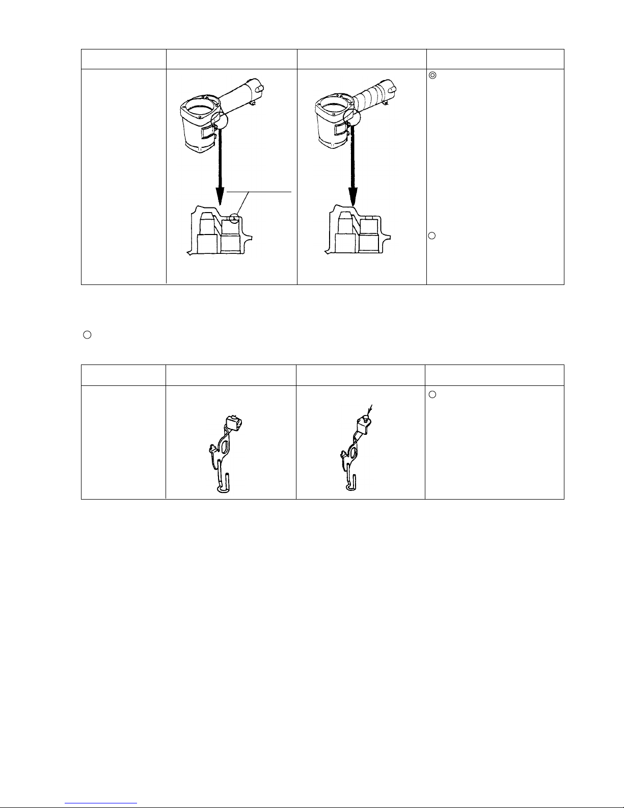
(2) Driving section
Parts that were changed for the Model NT 65A3 and not interchangeable with those of the Model NT 65A2
though they are similar to those of the Model NT 65A2
Pushing Lever [65]
Part
NT 65A3 NT 65A2 Caution
Without safety bolt
Safety bolt
The pushing lever for the
Model NT 65A3 is not
interchangeable with that of
the Model NT 65A2 because
the adjustment method is
different (safety bolt is not
provided).
The parts of the output section except the above are common to those of the Model NT 65A2.
The parts of the driving section except the above are common to those of the Model NT 65A2.
 Loading...