

Page 1
Instruction and safety manual
Mode d’emploi et consignes de sécurité
Manual de instrucciones y seguridad
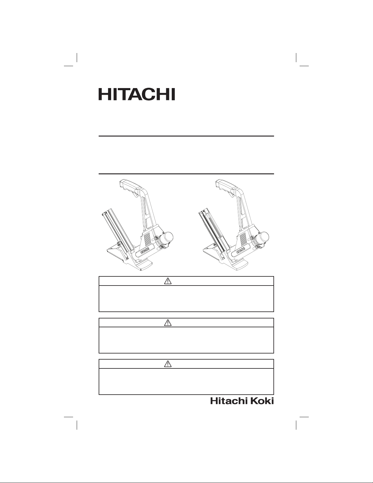
Model Flooring Nailer / Flooring Stapler
Modèle Cloueuse / brocheuse à plancher
Modelo Pistola de clavos para pisos /
NT50AF /
N5009AF
Grapadora para pisos
NT50AF N5009AF
DANGER
Improper use of this Tool can result in death or serious injury!
This Manual contains important information about product safety.
Read and understand this Manual before operating the Tool.
Never allow anyone (to handle this tool) who has not reviewed this manual.
DANGER
L’utilisation inadéquate de cet outil peut causer une blessure grave et même mortelle!
Ce manuel contient d’importantes consignes de sécurité. Lire le manuel attentivement
avant d’utiliser l’outil.
Ne jamais laisser une personne qui n’a pas lu le manuel utiliser l’outil.
PELIGRO
¡El uso incorrecto de esta pistola de clavos puede ocasionar lesiones graves o la muerte!
Este manual contiene información importante acerca de la seguridad del producto.
Lea y comprenda este manual antes de usar la pistola de clavos.
No permita nunca el uso de esta herramienta por parte de alguien que no haya leído este manual.
1
1
Page 2

English
IMPORTANT SAFETY INFORMATION ........3
DEFINITIONS OF SIGNAL WORDS ............. 3
SAFETY
IMPORTANT SAFETY INSTRUCTIONS
FOR USING TOOLS .................................4
IMPORTANT SAFETY INSTRUCTIONS
FOR USING NT50AF AND N5009AF
FLOORING TOOLS ................................... 9
EMPLOYER’S RESPONSIBILITIES .............. 9
OPERATION
NAME OF PARTS .......................................10
SPECIFICATIONS ....................................... 12
FASTENER SELECTION ............................. 13
ACCESSORIES ...........................................15
STANDARD ACCESSORIES .................. 15
OPTIONAL ACCESSORIES ....................15
CONTENTS
Page
APPLICATIONS ...........................................15
BEFORE OPERATION ................................. 15
WORKING ENVIRONMENT ................... 15
AIR SUPPLY ............................................ 16
LUBRICATION ........................................ 18
COLD WEATHER CARE ..........................18
TESTING THE TOOL .............................. 19
ADJUSTING AIR PRESSURE ................20
LOADING FASTENERS .......................... 20
TOOL OPERATION ..................................... 22
METHODS OF OPERATION ................... 23
INSTALLING TONGUE AND
GROOVE FLOORING .............................. 25
MAINTENANCE
MAINTENANCE AND INSPECTION .......... 27
SERVICE AND REPAIRS ............................. 29
PARTS LIST................................................. 32
Page
Français
SÉCURITÉ ...................................................36
DÉFINITION DES TERMES DE
SIGNALISATION .................................... 36
SÉCURITÉ
IMPORTANTES CONSIGNES DE SÉCURITÉ
POUR L’UTILISATION DES OUTILS ...... 37
IMPORTANTES CONSIGNES DE SÉCURITÉ
POUR L’UTILISATION DES OUTILS
À PLANCHER NT50AF ET N5009AF .....43
RESPONSABILITÉS DE L’EMPLOYEUR .... 43
FONCTIONNEMENT
NOM DES PIÈCES ......................................44
FICHE TECHNIQUE ....................................46
CHOIX DES ATTACHES ............................. 47
ACCESSOIRES ...........................................49
ACCESSOIRES STANDARDS ................ 49
ACCESSOIRES FACULTATIFS ...............49
Español
INFORMACION IMPORTANTE DE SEGURIDAD ...72
DEFINICIONES DE LAS PALABRAS DE AVISO .....72
SEGURIDAD
INSTRUCCIONES IMPORTANTES DE SEGU‑
RIDAD PARA USAR HERRAMIENTAS .............73
INSTRUCCIONES IMPORTANTES DE SEGU‑
RIDAD PARA USAR LAS HERRAMIENTAS
PARA PISOS NT50AF Y N5009AF .....................78
RESPONSABILIDADES DEL EMPLEADOR ............79
FUNCIONAMIENTO
NOMBRE DE LAS PIEZAS ......................................80
ESPECIFICACIONES ................................................82
SELECCION DE LOS SUJETADORES ....................83
ACCESORIOS ..........................................................85
ACCESORIOS ESTANDARES ............................85
ACCESORIOS OPCIONALES .............................85
TABLE DES MATIERES
Page
ÍNDICE
Página
UTILISATIONS ............................................49
AVANT DE COMMENCER .......................... 49
ENVIRONNEMENT DE TRAVAIL ...........49
ALIMENTATION EN AIR.........................50
LUBRIFICATION ..................................... 52
SOINS PAR TEMPS FROID .................... 52
ESSAI DE L’OUTIL .................................. 52
RÉGLAGE DE LA PRESSION D’AIR ......54
CHARGEMENT DES ATTACHES ........... 54
FONCTIONNEMENT DE L’OUTIL ..............56
MODES D’UTILISATION ........................ 57
POSE DE LAMES DE BOIS
EMBOUVETÉES .....................................59
ENTRETIEN
ENTRETIEN ET INSPECTION ....................61
SERVICE ET RÉPARATION .........................63
LISTE DES PIÈCES ..................................... 68
APLICACIONES .......................................................85
ANTES DEL FUNCIONAMIENTO ...........................85
AMBIENTE DE TRABAJO ..................................85
SUMINISTRO DE AIRE .......................................86
LUBRICACION ....................................................88
CUIDADO EN CLIMA FRIO.................................88
PRUEBA DE LA HERRAMIENTA ........................89
AJUSTE LA PRESION DE AIRE .........................90
COLOCACION DE SUJETADORES ....................90
FUNCIONAMIENTO DE LA HERRAMIENTA .........92
METODOS DE FUNCIONAMIENTO ..................93
INSTALACION DE PISOS DE RANURA
Y LENGÜETA .....................................................95
MANTENIMIENTO
MANTENIMIENTO E INSPECCION ........................97
SERVICIO Y REPARACIONES .................................99
LISTA DE PIEZAS ..................................................104
Page
Página
— 2 —
Page 3
English
IMPORTANT SAFETY INFORMATION
Read and understand tool labels and
all of the operating instructions, safety
precautions and warnings in this manual
before operating or maintaining this Tool.
Failure to follow warnings could result in
DEATH or SERIOUS INJURY.
Most accidents that result from the operation and maintenance of
Tools are caused by the failure to observe basic safety rules and
precautions. An accident can often be avoided by recognizing a
potentially hazardous situation before it occurs, and by observing
appropriate safety procedures.
Basic safety precautions are outlined in the “SAFETY” section of
this Manual and in the sections which contain the operation and
maintenance instructions.
Hazards that must be avoided to prevent bodily injury or machine
damage are identified by DANGERS and WARNINGS on the Tool
and in this Manual.
Never use this Tool for applications other than those specified in
this Manual.
DEFINITIONS OF SIGNAL WORDS
DANGER indicates an imminently hazardous situation, which if
WARNING indicates a potentially hazardous situation, which if not
CAUTION indicates a potentially hazardous situation, which if not
NOTE emphasizes essential information.
not avoided, will result in death or serious injury.
avoided, could result in death or serious injury.
avoided, may result in minor or moderate injury, or
may cause machine damage.
— 3 —
Page 4
English
SAFETY
IMPORTANT SAFETY INSTRUCTIONS
FOR USING TOOLS
READ ALL INSTRUCTIONS
DANGER
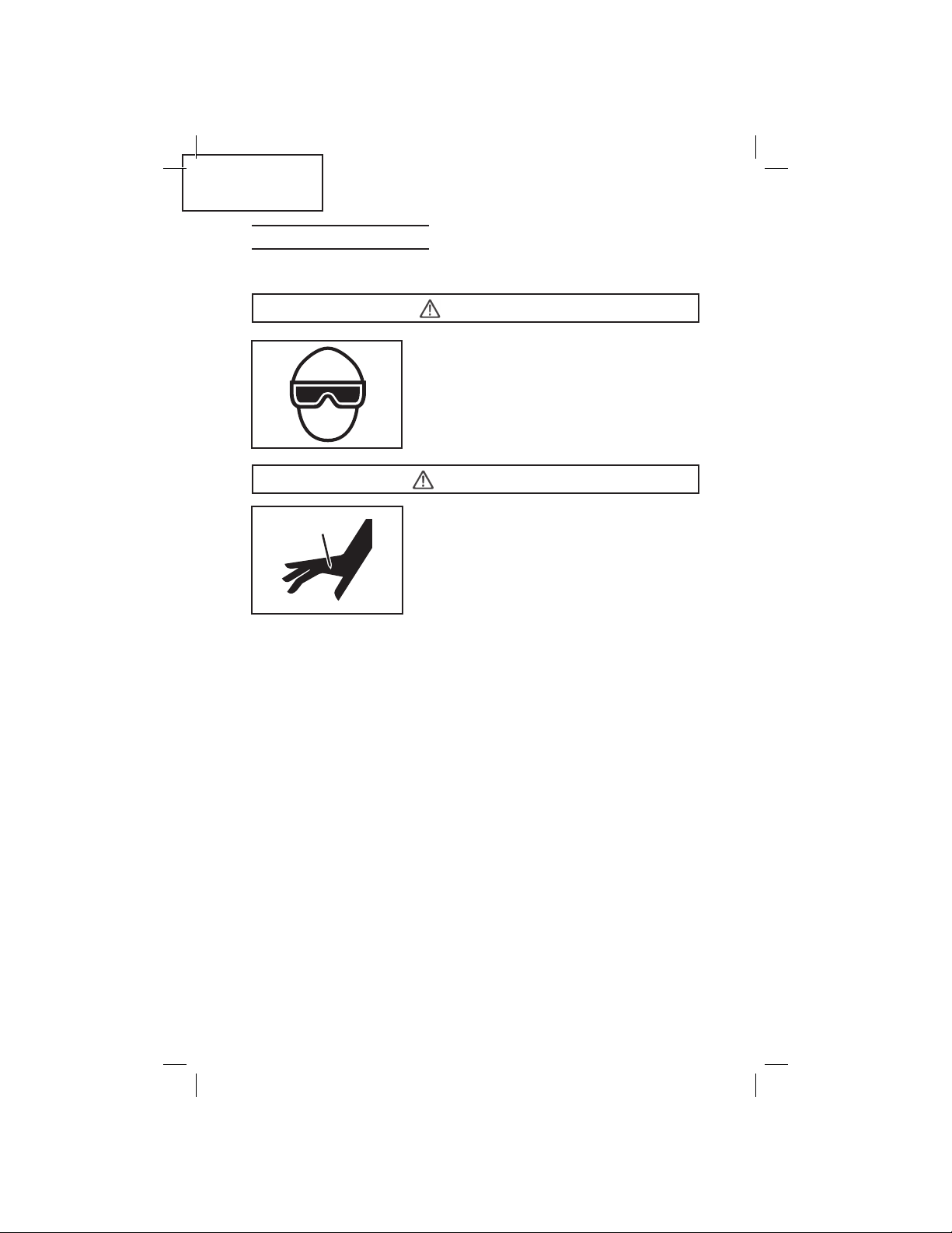
1. OPERATORS AND OTHERS IN WORK AREA MUST WEAR
SAFETY GLASSES WITH SIDE SHIELDS.
from the front and side.
The employer must enforce the use of safety glasses by the
Tool operator and others in work area.
When operating the Tool, always wear eye
safety glasses with side shields, and make
sure others in the work area wear safety
glasses, too.
Safety glasses must conform to the re‑
quirements of American National Stan‑
dards Institute, ANSI Z87.1 and provide
protection against flying particles both
2. NEVER USE OXYGEN OR OTHER BOTTLED GASES.
EXPLOSION MAY OCCUR.
3. NEVER POINT TOOL AT YOURSELF OR OTHERS IN WORK AREA.
Respect the Tool as a working implement.
Never use oxygen, combustible gases or
any other bottled gases as a power source
for the Tool.
Use of the above gases is dangerous, as
the Tool will explode.
Use only clean, dry, regulated compressed
air.
WARNING
Always assume the Tool contains
fasteners.
Never point the Tool at yourself, toward
yourself or others whether it contains
fasteners or not.
If fasteners are mistakenly driven, it can
lead to severe injuries.
Never engage in horseplay with the Tool.
— 4 —
Page 5
English
SAFETY ‑ Continued
WARNING
4. KEEP FINGERS AWAY FROM TRIGGER WHEN NOT DRIVING
FASTENERS TO AVOID ACCIDENTAL OPERATION.
Never carry the Tool with finger on safety trigger since you
could drive a fastener unintentionally and injure yourself or
someone else.
Always carry the Tool by the handle only.
5. CHOICE OF TRIGGERING METHOD IS IMPORTANT.
Please read and understand page 23 of “METHODS OF
OPERATION.”
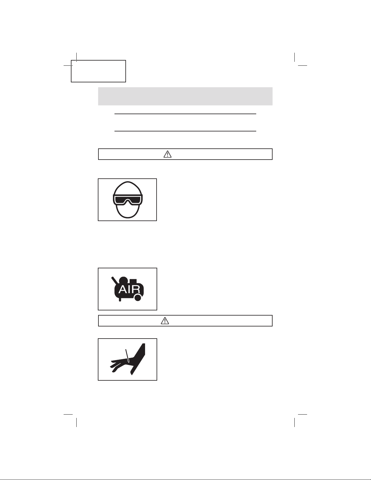
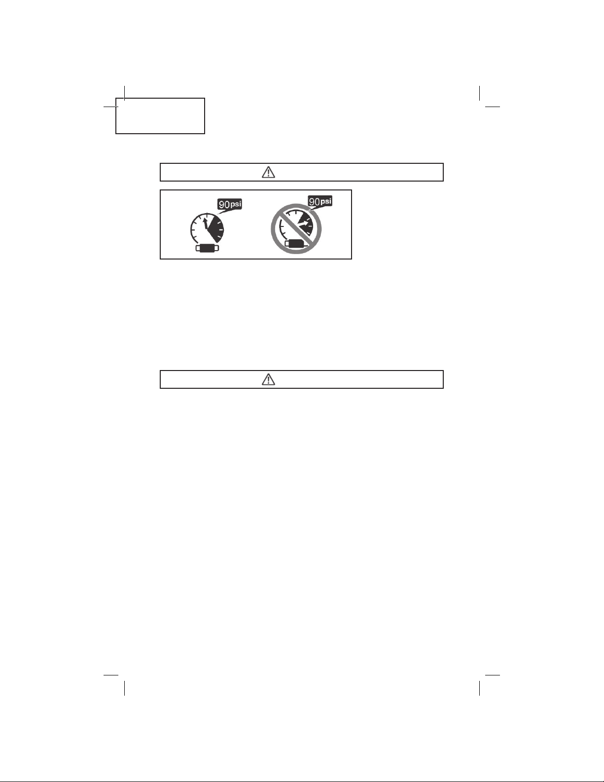
6. DO NOT EXCEED 90 psi. (6.2 bar 6.3 kgf/cm
exceeds 200 psi (13.7 bar 14 kgf/cm
7. ALWAYS WEAR EAR AND HEAD PROTECTION.
Always wear ear protection to protect your ears from loud
noise.
Always wear head protection conforming to ANSI Z89.1‑1986 to
protect your head from flying objects.
8. STORE TOOL PROPERLY.
When not in use, the Tool should be stored in a dry place. Keep
out of reach of children. Lock the storage area.
9. KEEP WORK AREA CLEAN.
Cluttered areas invite injuries. Clear all work areas of unneces‑
sary tools, debris, furniture, etc.
10. NEVER USE IN PRESENCE OF FLAMMABLE LIQUIDS OR
GASES.
The Tool produces sparks during operation. Never use the Tool
in sites containing lacquer, paint, benzine, thinner, gasoline,
gases, adhesive agents, and other materials which are combus‑
tible or explosive.
2
) as the Tool can burst.
2
)
Do not exceed
maximum recom‑
mended air pres‑
sure 90 psi (6.2 bar
6.3 kgf/cm
Never connect the
Tool to pressure
which potentially
2
)
— 5 —
Page 6

English
SAFETY ‑ Continued
WARNING
11. KEEP VISITORS AWAY.
Do not let visitors handle the Tool. All visitors should be kept
away from work area.
12. DRESS PROPERLY.
Do not wear loose clothing or jewelry as they can be caught in
moving parts. Rubber gloves and nonskid footwear are recom‑
mended when working indoors. Wear protective hair covering
to contain long hair.
13. NEVER USE NON RELIEVING COUPLER ON TOOL.
If a non relieving coupler is used on the Tool, the Tool can
remain charged with air after disconnecting and thus will be
able to drive a fastener even after disconnecting. The Tool and
air hose must have a hose coupling such that all pressure is
removed from the Tool when the coupling joint is disconnected.
14. CHECK SAFETY BEFORE USE.
Make sure the safety trigger operates properly. Never use the
Tool unless the safety trigger is operating properly, otherwise
the Tool could drive a fastener unexpectedly. Do not tamper
with or remove the safety trigger, otherwise the safety trigger
becomes inoperable.
15. KEEP ALL SCREWS AND COVERS TIGHTLY IN PLACE.
Keep all screws and covers tightly mounted. Check their condi‑
tion periodically. Never use the Tool if parts are missing or
damaged.
16. DO NOT LOAD FASTENERS WHILE RAM CAP IS CONTACTED
OR SAFETY TRIGGER IS OPERATED.
When loading fasteners into the Tool or when connecting the
air hose,
1) Do not contact the ram cap.
2) Do not depress the safety trigger; and
3) Keep the Tool pointed downward.
17. KEEP FACE, HANDS AND FEET AWAY FROM DISCHARGE AREA
DURING USE.
Never place your face, hands or feet closer than 8 inches (200
mm) from discharge area. A serious injury can result if the fas‑
teners are deflected by the work piece, or are driven away from
the point of entry.
— 6 —
Page 7
English
SAFETY ‑ Continued
WARNING
18. PLACE TOOL PROPERLY ON WORK PIECE.
Do not drive fasteners on top of other fasteners or with the Tool
are too steep of an angle; the fasteners can ricochet and hurt
someone.
19. BE CAREFUL OF DOUBLE FIRE DUE TO RECOIL.
Keep face, hands and body away from the discharge area of the
tool. The tool may bounce from the recoil of driving a fastener
and an unwanted second fastener may be driven possibly caus‑
ing injury.
20. DO NOT DRIVE FASTENERS INTO THIN BOARDS OR NEAR
CORNERS AND EDGES OF WORK PIECE.
The fasteners can be driven through or away from the work
piece and hit someone.
21. NEVER DRIVE FASTENERS FROM BOTH SIDES OF A WALL AT
THE SAME TIME.
The fasteners can be driven into and through the wall and hit a
person on the opposite side.
22. CHECK FOR LIVE WIRES.
Avoid the risk of severe electrical shock by checking for live
electrical wires that may be hidden by walls, floors or ceilings.
Turn off the breaker switch to ensure there are no live wires.
23. NEVER CARRY TOOL BY HOSE.
24. DO NOT OVERREACH.
Keep proper footing and balance at all times.
25. NEVER USE TOOL WHICH IS DEFECTIVE OR OPERATING ABNORMALLY.
If the Tool appears to be operating unusually, making strange
noises, or otherwise appears defective, stop using it imme‑
diately and arrange for repairs by a Hitachi authorized service
center.
26. DO NOT DISCONNECT AIR HOSE FROM TOOL WITH FINGER
ON TRIGGER.
The Tool can operate when re‑connected to an air supply.
— 7 —
Page 8
English
SAFETY ‑ Continued
WARNING
27. DISCONNECT AIR HOSE FROM TOOL WHEN:
1) Doing maintenance and inspection;
2) Loading fasteners;
3) Clearing a jam;
4) It is not in use;
5) Leaving work area;
6) Moving it to another location; and
7) Handing it to another person.
Never attempt to clear a jam or repair the Tool unless you have
disconnected air hose from the Tool and removed all remaining
fasteners from the Tool. The Tool should never be left unattend‑
ed since people who are not familiar with the Tool might handle
it and injure themselves.
28. STAY ALERT.
Watch what you are doing. Use common sense. Do not operate
the Tool when you are tired. The Tool should never be used by
you if you are under the influence of alcohol, drugs or medica‑
tion that makes you drowsy.
29. HANDLE TOOL CORRECTLY.
Operate the Tool according to the Manual. Never allow the
Tool to be operated by children, individuals unfamiliar with its
operation or unauthorized personnel.
30. NEVER USE TOOL FOR APPLICATIONS OTHER THAN THOSE
SPECIFIED IN THIS MANUAL.
31. HANDLE TOOL CAREFULLY.
Because of high air pressure in the Tool, cracks in the surface
are dangerous. To avoid this, do not drop the Tool or strike the
Tool against hard surfaces; and do not scratch or engrave signs
on the Tool. Handle the Tool carefully.
32. MAINTAIN TOOL WITH CARE.
Keep the Tool clean and lubricated for better and safer perfor‑
mance.
33. USE ONLY PARTS, ACCESSORIES OR FASTENERS SUPPLIED
OR RECOMMENDED BY HITACHI.
Unauthorized parts, accessories, or fasteners may void your
warranty and can lead to malfunction and resulting injuries.
Only service personnel trained by Hitachi, distributor or
employer shall repair the Tool.
— 8 —
Page 9
English
SAFETY ‑ Continued
WARNING
34. NEVER MODIFY OR ALTER A TOOL.
Doing so may cause it to malfunction and personal injuries may
result.
IMPORTANT SAFETY INSTRUCTIONS FOR USING
NT50AF AND N5009AF FLOORING TOOLS
WARNING
1. NEVER use a hammer with a loose head or splintered handle.
2. Do not tie, tape, or otherwise disable the safety trigger as this
could result in accidental discharge of the Tool causing injury to
yourself and others.
3. Do not strike the ram/actuator without pulling the safety trigger.
Hitting the Tool with the safety interlock engaged will severely
damage the safety mechanism and the Tool. This abuse and
damage is not covered by the warranty.
EMPLOYER’S RESPONSIBILITIES
1. Ensure that this MANUAL is available to operators and person‑
nel performing maintenance.
2. Ensure that Tools are used only when operators and others in
work area are wearing EYE PROTECTION.
3. Enforce the use of EYE PROTECTION by operators and others in
work area.
4. Keep Tools in safe working order.
5. Maintain Tools properly.
6. Ensure that Tools which require repair are not further used
before repair.
SAVE THIS MANUAL AND KEEP
IT AVAILABLE FOR OTHERS!
— 9 —
Page 10

English
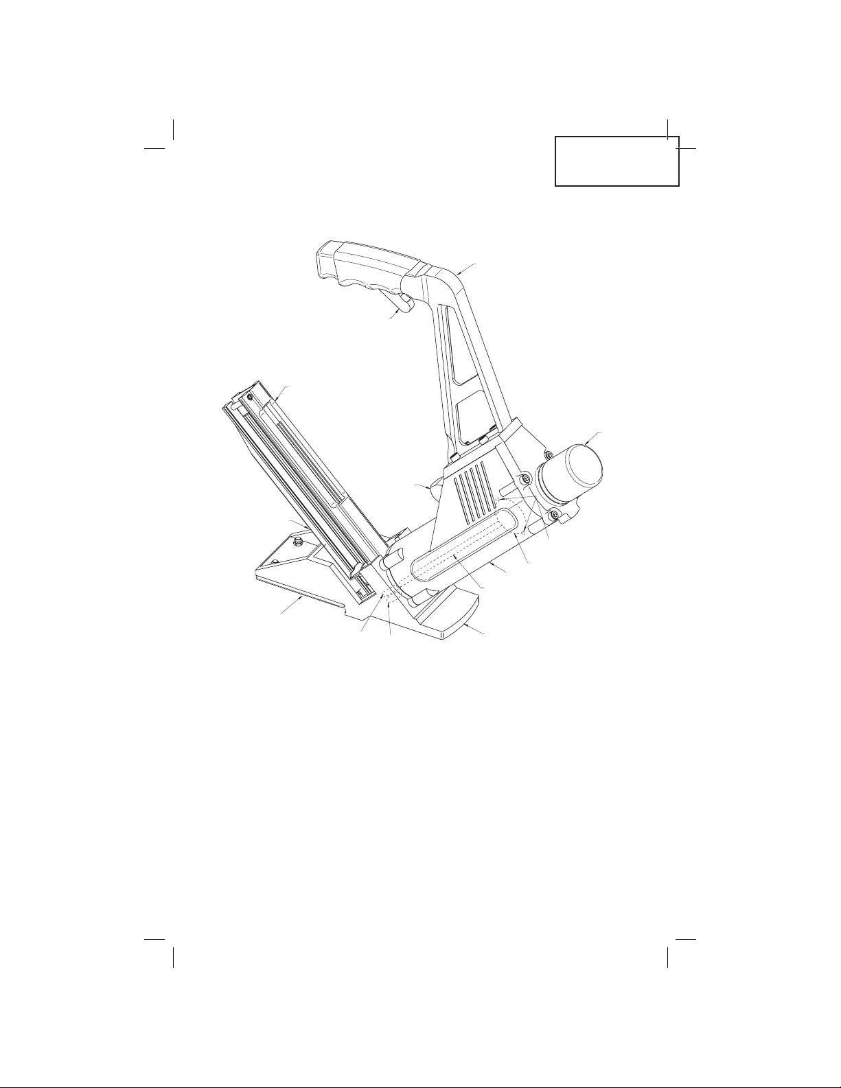
BO DY
RA M
CA P
QU IC K
CO NN ECT
- M ALE
DR IV ER GUIDE PLAT E
NO SE
DR IV ER BLADE
PI ST ON
O- RI NG - PISTON O . D .
PU SH ER
SH OE BASE
SH OE
MA GA ZIN E
HA ND LE
SA FE TY TRIGGER
OPERATION
NOTE:
The information contained in this Manual is designed to
assist you in the safe operation of the Tool.
Some illustrations in this Manual may show details or at‑
tachments that differ from those on your own Tool.
NAME OF PARTS
NT50AF
— 10 —
Page 11
BO DY
RA M
CA P
QU IC K
CO NN ECT
- M ALE
DR IV ER GUIDE PLAT E
NO SE
DR IV ER BLADE
PI ST ON
O- RI NG - PISTON O . D .
PU SH ER
SH OE BASE
SH OE
MA GA ZIN E
HA ND LE
SA FE TY TRIGGER
N5009AF
English
— 11 —
Page 12

English
SPECIFICATIONS
Model NT50AF
Operating Pressure 70‑90 psi (4.8‑6.2 bar
4.9‑6.3 kgf/cm
Actuation Hammer Actuated with Safety
Interlock
Dimensions
Length x Height x Width
18” x 18‑3/4” x 3‑1/8”
(457mm x 476mm x 79mm)
Weight 9 lbs (4.1 kg)
Nail Capacity 150 Nails
Air Consumption .058 ft3/cycle @ 80 psi
(1.64 ltr/cycle @ 5.5 bar)
(1.64 ltr/cycle @ 5.6 kgf/cm
Air Inlet 3/8” NPT Thread
Model N5009AF
Operating Pressure 70‑90 psi (4.8‑6.2 bar
4.9‑6.3 kgf/cm
Actuation Hammer Actuated with Safety
Interlock
Diensions
Length x Height x Width
18” x 18‑3/4” x 3‑1/8”
(457mm x 476mm x 79mm)
Weight 9.1 lbs (4.1 kg)
Staple Capacity 150 Staples
Air Consumption .058 ft3/cycle @ 80 psi
(1.64 ltr/cycle @ 5.5 bar)
(1.64 ltr/cycle @ 5.6 kgf/cm
Air Inlet 3/8” NPT Thread
2
)
2
)
2
)
2
)
— 12 —
Page 13
English
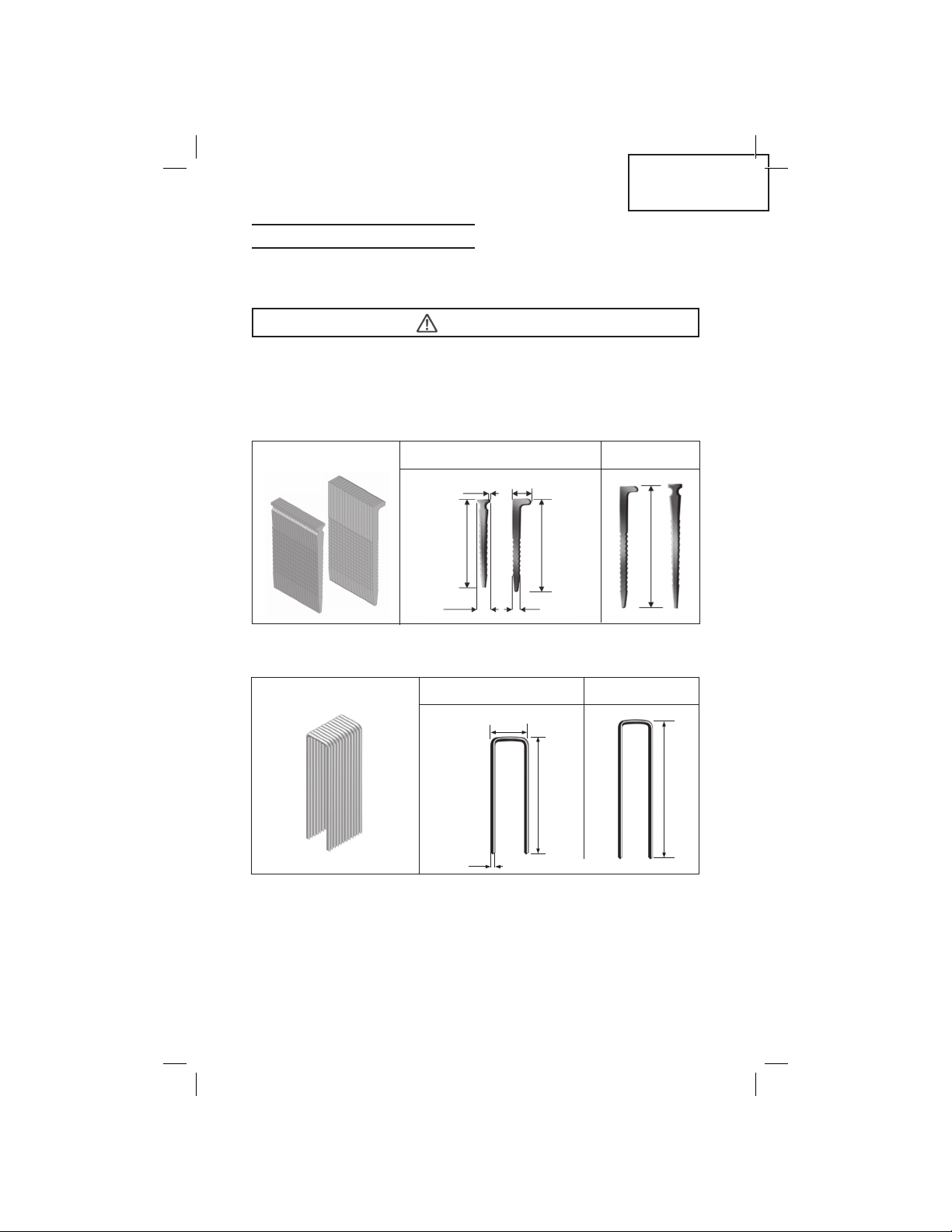
FASTENER SELECTION
Only fasteners shown in the table below can be driven with
this Tool.
WARNING
Be sure to use only the genuine HITACHI fasteners for the NT50AF /
N5009AF. The use of any other fasteners can result in tool malfunction and/or fastener breakdown, leading to serious injuries.
Dimensions of nails (NT50AF)
Min. Max.16 gauge T & L nails
.06”(1.53mm)
.26”(6.60mm)
1‑3/16” (30mm)
.23”(5.80mm) .12”(3.15mm)
1‑1/2” (38mm)
Dimensions of staples (N5009AF)
Min. Max.15 gauge staples
1/2”(13mm)
1‑1/2”(38mm)
.07”(1.8mm)
2” (50mm)
2”(50mm)
— 13 —
Page 14
English
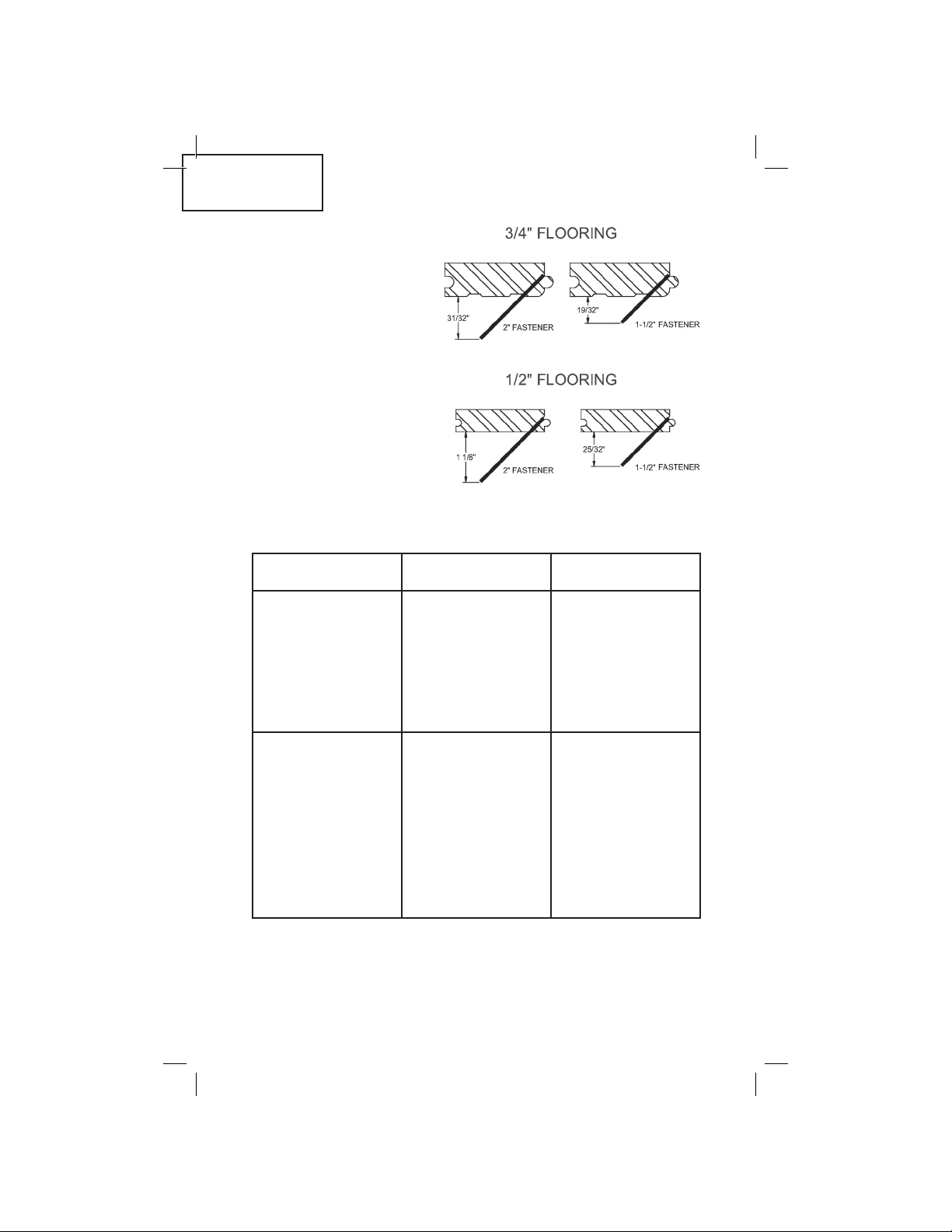
The NT50AF Pneumatic
Flooring Nailer, with the
standard shoe, drives 1‑1/2”
and the 2” T or L nails into
the tongue and groove
flooring at a 45 degree
angle. The orientation of
the fastener is as depicted
above.
The N5009AF Pneumatic
Flooring Stapler, with the
standard shoe, drives 1‑1/2”
and the 2” staples into the
tongue and groove flooring
at a 45 degree angle. The
orientation of the fastener is
as depicted above.
Fastener Application Chart
FASTENER APPLICATION T&G FLOORING
2” T‑Nail / L‑Nail /
Staple
Angle Fastener onto
5/8” ‑ 3/4” under‑
layment over joist
construction
THICKNESS
3/8”, 1/2”, 9/16”, 5/8”,
3/4”, 33/32”
1‑1/2” T‑Nail / L‑Nail /
Staple
Surface (face) Fas‑
tener onto 5/8” ‑ 3/4”
underlayment over
joist construction
Angle Fastener onto
5/8” ‑ 3/4” underlay‑
ment over concrete
slab or hydronic heat‑
ing systems
Surface (face)
Fastener onto 5/8” ‑
3/4” underlayment
over concrete slab
or hydronic heating
systems
— 14 —
3/4”, 33/32”
33/32”
Page 15
ACCESSORIES
WARNING
Accessories other than those shown below can lead to malfunction and resulting injuries.
STANDARD ACCESSORIES
1. Hammer
2. Shoe Pad 1/2”
3. Wrench Set (Service Parts Kit)
4. Safety Glasses
5. Carrying Case
OPTIONAL ACCESSORIES
1. 9/16” ‑ 3/4” Pre‑Finished (wide profile) Flooring Shoe
(Code No. 330389)
2. Nail Set for “T” and “L” Nails (NT50AF) (Code No. 330328)
English
NOTE: Accessories are subject to change without any
obligation on the part of HITACHI.
APPLICATIONS
For installation of tongue and groove solid wood and engineered
hardwood flooring.
BEFORE OPERATION
Read over section titled “SAFETY” (pages 4-9).
Make sure of the following before operation.
WORKING ENVIRONMENT
WARNING
No flammable gas, liquid or other flammable objects at work-
•
site.
Clear the area of children or unauthorized personnel.
•
— 15 —
Page 16
English
AIR SUPPLY
DANGER
NEVER use oxygen or other bottled
•
gases. Explosion may occur.
WARNING
Never connect Tool to pressure which potentially exceeds 200
•
psi (13.7 bar 14 kgf/cm
Never use non relieving coupler on Tool.
•
1. Power Source
V Use only clean, dry, regulated compressed air as a power source
for this Tool
V Air compressors used to supply compressed air to this Tool
must comply with the requirements of the latest version of ANSI
Standard B 19.3 “Safety Standard For Compressors For Process
Industries.”
V Moisture or oil in the air compressor may accelerate wear and
corrosion in the Tool.
Drain daily.
V Air volume is as important as air pressure. The air volume
supplied to the tool may be inadequate because of undersized
fittings and hoses or from the effects of dirt and water in the
system. Restricted air flow will prevent the tool from receiving
an adequate volume of air, even though the pressure reading is
high. The results will be slow operation, jamming, miss‑feeds
or reduced driving power. Before evaluating tool problems for
these symptoms, trace the air supply from the tool to the supply
source for restrictive connectors, swivel fittings, low points con‑
taining water and anything else that would prevent full volume
flow of air to the tool.
2
).
2. Filter‑Regulator‑Lubricator
V A pressure regulator with an operating pressure of 0‑125 psi
(0‑8.6 bar 0‑8.8 kgf/cm
pressure for safe operation of this Tool. Do not connect this Tool
to air pressure which can potentially exceed 200 psi as Tool may
fracture or burst, possibly causing injury.
V Filter‑Regulator‑Lubricator units supply an optimum condition
for the Tool and extend the Tool life.
2
) is required to control the operating
— 16 —
Page 17

English
These units should always be used
Filter .............. The filter removes moisture and dirt mixed in
Regulator ...... The regulator controls the operating pressure for
Lubricator ..... The lubricator supplies an oil mist to the Tool.
compressed air. Drain daily unless fitted with an
automatic drain. Keep the filter clean by regular
maintenance.
safe operation of the Tool. Inspect the regulator
before operation to be sure it operates properly.
Inspect the lubricator before operation to be sure
the supply of lubricant is adequate. Use Hitachi
pneumatic tool lubricant.
3. Air Hose
Air hoses should have a minimum of 150 psi (10.4 bar 10.6 kgf/
2
cm
) working pressure rating or 150 percent of the maximum
pressure that could be produced in the air system. The supply
hose should contain a fitting that will provide “quick disconnect‑
ing” from the male plug on the Tool.
4. Hose Coupling
Install a male plug on the Tool which is free flowing and which
will release air pressure from the Tool when disconnected from
the supply source. This Tool uses a 3/8” NPT. male plug. The in‑
side diameter should be .275” (7mm) or larger. The fitting must
be capable of discharging Tool air pressure when disconnected
from the air supply.
5. Air Consumption
The Tool requires 4.2 cfm of free air to operate at the rate of 60
fasteners per minute @ 80 psi. Take the actual rate at which the
Tool will be run to determine the amount of air required. For in‑
stance, if your fastener usage averages 30 fasteners per minute,
you need 50% of the Tools cfm.
6. Operating Pressure
70 to 90 psi. Select the operating pressure within this range
for best fastener performance. DO NOT EXCEED THIS RECOM‑
MENDED OPERATING PRESSURE.
— 17 —
Page 18

English
LUBRICATION
Frequent, but not excessive, lubrication is required for best perfor‑
mance. Oil added through the air line connection will lubricate the
internal parts. Use Pneumatic Tool Lubricant, Mobil Velocite #10, or
equivalent. Do not use detergent oil or additives as these lubricants
will cause accelerated wear to the seals and Piston Cushion in the
Tool, resulting in poor tool performance and frequent Tool mainte‑
nance.
If no airline lubricator is used, add oil during use into the air fitting
on the Tool once or twice a day. Only a few drops of oil at a time
are necessary. Too much oil will only collect inside the Tool and will
be noticeable in the exhaust cycle.
COLD WEATHER CARE
For cold weather operation, near and below freezing, the moisture
in the air line may freeze and prevent Tool operation. We recom‑
mend the use of WINTER FORMULA air tool lubricant (NEW‑MATIC
Winter Formula or equivalent) or permanent anti freeze (ethylene
glycol) as a cold weather lubricant.
CAUTION: Do not store tools in a cold weather environment to
prevent frost or ice formation on the tools operating valves and
mechanisms that could cause tool failure.
NOTE: Some commercial air line drying liquids are harmful to
O‑rings and seals – do not use these low temperature air dryers
without checking compatibility.
CAUTION
Do not operate the Tool at high pressure without fasteners
— 18 —
Page 19

English
TESTING THE TOOL
WARNING
Operators and others in work area
•
MUST wear safety glasses with side
shields which conforms to ANSI Z87.1
specifications.
WARNING
Never use Tool unless safety trigger is working properly
•
Manufacturer recommends before each use, check all Screws and
Nuts to make sure they are tight and have not “jarred loose” from
vibration and use. (Shoe, Shoe Base and Pad, Magazine, Magazine
Retainer Bracket, Handle, etc.).
Manufacturer recommends before each use, check the Driver Blade
tip for deformation & breakage to prevent improper driving of fas‑
teners and/or to prevent damage to the Tool and Flooring.
Before actually beginning the fastening work, test the Tool by using
the check list below.
Conduct the tests in the following order.
If abnormal operation occurs, stop using the Tool and contact a
Hitachi authorized service center immediately.
1) Adjust the air pressure to 70 psi (4.8 bar , 4.9 kgf/cm
M Connect the air hose.
M Do not load any fasteners in the Tool.
M The Tool must not leak air.
2) Pull the safety trigger.
M The Tool must not operate.
3) Remove the finger from the trigger and contact the ram cap.
M The Tool must not operate.
4) First, pull the safety trigger. Next, contact the ram cap.
M The Tool must operate.
— 19 —
2
)
Page 20
English
ADJUSTING AIR PRESSURE
WARNING
Do not exceed
•
90 psi (6.2 bar
6.3 kgf/cm
2
)
Adjust the air pressure at recommended operating pressure 70 – 90
psi (4.9 – 6.2 bar 5 – 6.3 kgf/cm
ers and the hardness of workpiece.
The correct air pressure is the lowest pressure which will do the
job. Using the Tool at a higher than required air pressure unneces‑
sarily over stresses the Tool.
2
) according to the length of fasten‑
LOADING FASTENERS
WARNING
When loading fasteners into the Tool,
•
1) Do not contact the ram cap.
2) Do not depress the safety trigger; and
3) Keep the Tool pointed downward.
TO PREVENT ACCIDENTAL INJURIES:
Never place a hand or any other part of the body in Tool discharge area of Tool while the air supply is connected.
Never point the Tool at anyone else.
Never engage in horseplay.
Never pull the trigger unless nose is directed at the work.
Always handle the Tool with care.
Do not pull the trigger or depress the trip mechanism while
loading the Tool.
— 20 —
Page 21

English
NAIL LOADING:
(Hitachi NT50AF Pneumatic Flooring Nailer)
Insert “L” or “T” Nails in the end of the magazine as shown. Pull
pusher assembly back to engage pusher to strip of Nails. The Tool
is now ready to operate.
STAPLE LOADING:
(Hitachi N5009AF Pneumatic Flooring Stapler)
Pull pusher back. Insert a clip of staples. Push pusher forward to
engage the staple clip. The Tool is now ready to operate.
— 21 —
Page 22
English
TOOL OPERATION
Read section titled “SAFETY” ( pages 4-9)
DANGER
Operators and others in work area
•
MUST wear safety glasses with side
shields which conforms to ANSI Z87.1
specifications.
WARNING
NEVER point tool at yourself or others
•
in work area.
Keep fingers AWAY from trigger when
•
not driving fasteners to avoid accidental operation.
Never place your face, hands or feet
•
discharge area when using. The Tool may bounce from the recoil
of driving a fastener and an unwanted second fastener may be
driven possibly causing injury.
Check operation of the safety mechanism frequently. Do not
•
use the Tool if the safety is not working correctly as accidental driving of a fastener may result. Do not interfere with the
proper operation of the safety mechanism.
The safety trigger is a safety device and should only be pulled
•
when the Tool is in proper position on the work surface and
before the ram/actuator is struck with the mallet.
Do not tie or tape down the safety trigger as the Tool could
•
discharge if dropped on the plunger. The Tool will not operate
unless the trigger is pulled before striking the ram/actuator
with the mallet.
Do not use the safety as a disabling mechanism for the ram/
•
actuator in order to use the Tool to rack the wood. This will
severely damage the mechanism and the Tool. This abuse and
damage is not covered by the warranty. Use the mallet to rack
the flooring, not the Tool.
Do not strike the ram/actuator without pulling the safety trig-
•
ger! Hitting the Tool with the safety engaged will damage the
safety mechanism and the Tool.
Do not drive fasteners on top of other fasteners or with Tool at
•
too steep of an angle; fasteners can ricochet and hurt someone.
closer than 8 inches (200 mm) from
— 22 —
Page 23

Do not strike the ram/actuator or any part of the Tool with the
•
metal portion of the mallet. Use the rubber capped end only to
prevent possible injury and/or damage to the Tool.
Do not drive fasteners into thin boards or near corners and
•
edges of work piece. Fasteners can be driven through or away
from work piece and hit someone.
Do not overdrive fasteners. NOFMA states that one reason for
•
split tongues is overdriving.
Never use Tool which is defective or operating abnormally.
•
Do not use Tool as a hammer.
•
Disconnect air hose from Tool when:
•
1) It is not in use;
2) Leaving work area;
3) Moving it to another location; and
4) Handing it to another person.
Wear safety glasses and safety shoes for protection against
•
foreign objects.
Never use a Hammer with a loose head or splintered handle.
•
Use only fasteners from Hitachi.
•
Air supply hoses should have a minimum working pressure
•
rating of 150 psi or 150 percent of the maximum pressure produced in the power source, whichever is higher.
Check all hoses before connecting to ensure that they are free
•
from dirt, grit, or particles that could alter the performance of
the tool.
An airline Filter and In-Line Air Regulator adjustable to 125 psi
•
max are required.
NEVER use a defective tool. Replace worn or damaged parts
•
immediately. Be sure that the Safety Trigger and operating
mechanisms operate correctly and that all screws and seals are
securely tightened at all times.
English
METHODS OF OPERATION
After connection with power source is made, check to be sure that
the airline Regulator pressure is 70‑90 psi. Note: Some materials
may require a higher pressure in order to countersink the fastener.
Harder Material Flooring requires more pressure than typical Oak
or Maple. Face Nailing requires approximately 5 psi or more than
Angle Nailing.
Ensure that Tool is in proper working order and that there is no
leaking of air. If there is an air leak, Disconnect Immediately! Ar‑
range for repairs by a Hitachi authorized service center.
After being sure Tool is operable, place Tool in position to be used.
Always place the Tool in proper position against the flooring to be
fastened before depressing the trigger and striking the ram.
— 23 —
Page 24

English
The NT50AF Pneumatic Flooring Nailer and N5009AF Pneumatic
Flooring Stapler have a safety trigger that prevents accidental op‑
eration if ram cap is hit while connected to power source. Squeeze
safety lever to enable the Tool. Releasing the safety lever re‑engag‑
es the safety and renders the Tool inoperable.
To operate Tool, depress safety trigger while Tool is in position of
use, and tap the ram cap with a minimal stroke from the hammer.
If on the first initial operation a fastener does not eject into the
flooring, repeat hammer blow. This will ensure that the driver
blade/Piston is properly reset to allow the driver blade/piston to be
in the correct position to drive the fastener.
DO NOT OVERPOWER THE TOOL– A 90lb static force will oper‑
ate the Tool. This is easily achieved by a tap of the Hammer. If the
Flooring is warped or bowed, the ram can be hit firmly to tighten
the flooring. Try to avoid this constant wear, as abusive blows by
the hammer could damage tool and / or internal parts.
DO NOT HIT THE TOOL HARD
This Tool is pneumatically powered and requires only actuation by
depressing the safety trigger and tapping the ram head.
Note: The NT50AF Pneumatic Flooring Nailer and N5009AF Pneu‑
matic Flooring Stapler will not drive a fastener if the ram cap is
struck by hammer and the safety trigger is not depressed.
The NT50AF Pneumatic Flooring Nailer and N5009AF Pneumatic
Flooring Stapler are user‑friendly and following these simple
instructions, will insure a very high quality hardwood flooring
installation.
If the fastener is not properly seated, increase pressure incremen‑
tally until fastener is seated. DO NOT EXCEED 90 PSI!
WARNING
Keep your finger off the trigger except during fastening opera-
•
tion, because serious injury could result if the contact ram
accidentally contacts you or others in the work area.
Keep hands and body away from the discharge area. The Tool
•
may bounce from recoil of driving a fastener and unwanted
subsequent fastener may be driven, possibly causing injury.
Some types of loaded fasteners can spark out of the muzzle
•
during a driving operation. Exercise caution!
— 24 —
Page 25

English
INSTALLING TONGUE AND GROOVE FLOORING
Caution regarding use of this Tool to install pre-finished flooring
This Tool was designed for use in installing unfinished hardwood
flooring. It can be used to install pre‑finished flooring when used
with the pre‑finish flooring accessory shoe; however, caution must
be used to ensure that the finish is not damaged by the Tool. In all
flooring applications, it is recommended that the Tool be tested on
a sample section to be certain that the Tool and technique of use do
not leave marks on the finish. This procedure should be followed
before each job due to variations in flooring and Tool condition.
After squaring the floor and allowing for expansion as recommend‑
ed by the Wood Flooring Industry (NWFA, NOFMA and MFMA),
install felt vapor barrier and use chalk line to identify location of
subfloor nails prior to racking wood to be installed. This will help
prevent hitting subfloor nails which can cause damage to the driver
blade and jamming. Place the grooved edge of the first row of
flooring towards the wall on the side of the room from which you
are starting.
Face nail first four (4) rows of flooring.
Install the tongue and groove shoe.
Place the groove of the fifth row of flooring over the tongue of the
fourth row of flooring and tighten using the hammer. Depress the
safety trigger, and tap ram head of the Tool with the tongue and
groove shoe installed.
Slide the Tool along the tongue of the flooring to the location at
which you desire to place the next fastener.
Continue until you have completely fastened all but the last five (5)
rows of flooring.
Install and face nail in place the remaining five (5) rows of flooring.
— 25 —
Page 26

English
These steps are provided as a simple guideline for proper instal‑
lation technique. Should you encounter a situation not covered
here or have additional questions regarding the NT50AF Pneumatic
Flooring Nailer and N5009AF Pneumatic Flooring Stapler and their
use please contact us at 866‑775‑9429. Should you require detailed
information regarding wood flooring installation we suggest you
contact:
National Oak Flooring Manufacturers Association
901‑526‑5016
Visit their web site http://www.nofma.org.
or
National Wood Flooring Association
800‑422‑4556
Visit their web site http://www.woodfloors.org.
or
Maple Flooring Manufacturers Association, Inc.
847‑480‑9138
Visit their web site http://www.maplefloor.org.
— 26 —
Page 27
MAINTENANCE
English
NOTE:
The information contained in this Manual is designed to
assist you in the safe maintenance of the Tool.
Some illustrations in this Manual may show details or at‑
tachments that differ from those on your own Tool.
MAINTENANCE AND INSPECTION
Read section titled “SAFETY” (page 4-9)
WARNING
Disconnect air hose and remove all fasteners from Tool when:
•
1) doing maintenance and inspection; and
2) clearing a jam.
1. Resetting the Piston / Driver Blade
Disconnect from the Air source.
Unload all of the fasteners from the magazine.
Make sure there are no fasteners in the guide chamber.
Reconnect the air source to the Tool.
While squeezing the safety lever, push the ram down and hold
for three (3) seconds and release.
Load fasteners and proceed with the operation of the Tool.
2. Inspecting the Magazine
o
DISCONNECT THE AIR HOSE
o
Clean the magazine. Remove dust or wooden tips which may
have accumulated in the magazine.
3. Storing
o
When not in use for an extended period, apply a thin coat of the
lubricant to the steel parts to avoid rust.
o
Do not store the Tool in a cold weather environment. When not
in use, the Tool should be stored in a warm and dry place.
o
Keep out of reach of children.
— 27 —
Page 28
English
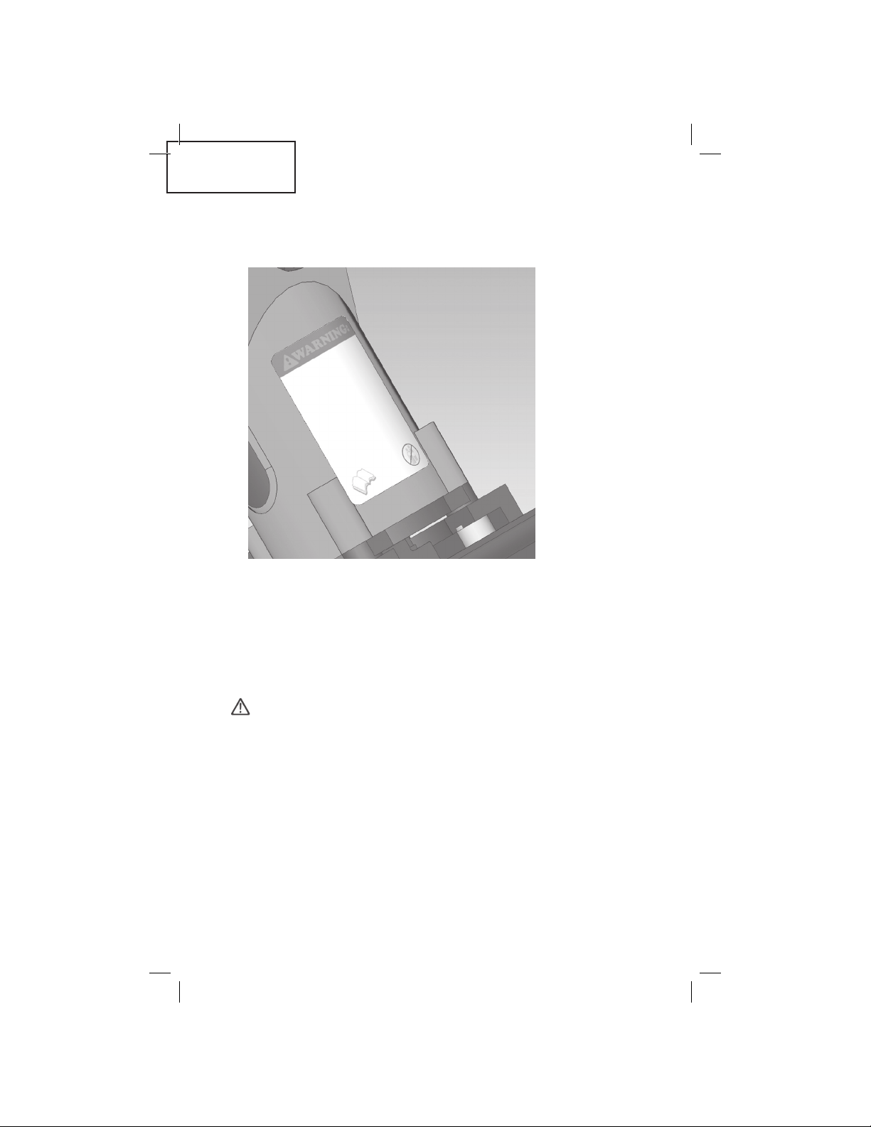
4. Warning Label
Change the WARNING LABEL if missing or damaged. A new
WARNING LABEL is available from a Hitachi Authorized Service
Center.
5. Maintenance Chart (see page 29)
6. Operator Troubleshooting (see page 30)
7. Service Parts List
A. Item No.
B. Code No.
C. Description
CAUTION
Repair, modification and inspection of Hitachi Power Tools
•
must be carried out by an Hitachi Authorized Service Center.
This Parts List will be helpful if presented with the tool to the
Hitachi Authorized Service Center when requesting repair or
other maintenance. In the operation and maintenance of power
tools, the safety regulations and standards prescribed in each
country must be observed.
MODIFICATIONS:
Hitachi Power Tools are constantly being improved and modified
to incorporate the latest technological advancements. Accordingly,
some parts (i.e.: code numbers and/or design) may be changed
without prior notice.
— 28 —
Page 29
English
SERVICE AND REPAIRS
WARNING
Only service personnel trained by Hitachi, distributor or em-
•
ployer shall repair the Tool.
Use only Hitachi parts supplied or recommended by Hitachi for
•
repair.
All quality Tools will eventually require servicing or replacement of
parts because of wear from normal use.
In order to achieve the optimal performance of the NT50AF Pneu‑
matic Flooring Nailer and N5009AF Pneumatic Flooring Stapler
preventative maintenance is recommended.
NOTE:
Specifications are subject to change without any obligation
on the part of HITACHI.
Maintenance Chart
ACTION WHY HOW
Drain air line filter
daily
Keep lubricator filled. Keep the Tool lubri‑
Clean filter element ‑
then blow air through
filter in direction oppo‑
site to normal flow.
Clean magazine and
feeder mechanism.
Keep safety trigger
working properly.
Lubricate the Tool after
use.
Drain air compressor. Keep the Tool operat‑
Prevent accumulation
of moisture and dirt.
cated.
Prevent clogging of
filter with dirt.
Prevent a jam. Blow clean daily.
Promote operator
safety and efficient
Tool operation.
Extend the life of the
Tool.
ing properly.
Open manual
petcock.
Fill with Hitachi pneu‑
matic tool lubricant.
Follow manufacturer’s
instructions.
Blow clean daily.
Supply 5‑10 drops of
lubricant into the Tool.
Open petcock on air
compressor tank.
— 29 —
Page 30

English
Operator Troubleshooting
Most minor problems can be resolved quickly and easily using
the table below.
If problems persist, contact a Hitachi authorized service center
for assistance.
PROBLEM OR
QUESTION
Trigger valve housing
leaks air
Trigger valve stem
leaks air
Frame/nose leaks air Loose nose screws Tighten and recheck.
Frame/cap leaks air Damaged seal Contact Hitachi for
Failure to cycle Air supply restriction Check air supply
Lack of power; slow to
cycle
O‑ring cut or cracked. Contact Hitachi for
O‑ring/seals cut or
cracked
O‑ring is cut or cracked Contact Hitachi for
Piston cushion is
cracked/ worn
Loose cap screws Tighten and recheck.
Tool dry, lack of lubri‑
cation
Worn head valve O‑
rings
Tool dry, lack of lubri‑
cation
Broken cylinder cap
spring
O‑rings/seals cut or
cracked
Exhaust blocked Contact Hitachi for
Dirt/tar build up on
driver
Head valve dry Contact Hitachi for
Air pressure too low Check air supply
CAUSE CORRECTIVE ACTION
replacement.
Contact Hitachi for
replacement.
replacement.
Contact Hitachi for
replacement.
replacement.
equipment
Use Air Tool Lubricant
Contact Hitachi for
replacement.
Use Air Tool Lubricant
Contact Hitachi for
replacement.
Contact Hitachi for
replacement.
replacement.
Contact Hitachi for
replacement.
replacement.
equipment
‑ Continued ‑
— 30 —
Page 31

English
Skipping fasteners;
intermittent feed
Fasteners jam in Tool Driver channel worn Contact Hitachi for
Worn piston cushion Contact Hitachi for
Tar/dirt in driver chan‑
nel
Air restriction/inade‑
quate air flow through
quick disconnect
socket and plug
Worn piston O‑ring Contact Hitachi for
Tool dry, lack of lubri‑
cation
Damaged pusher
spring
Low air pressure Check air supply
Loose magazine nose
screws
Fasteners too short
for tool
Bent fasteners Discontinue use of
Wrong size fasteners Use only recommend‑
Broken/chipped driver Contact Hitachi for
Dry/dirty magazine Clean / lubricate; Use
Worn magazine Contact Hitachi for
Wrong size fasteners Use only recommend‑
Bent fasteners Discontinue use of
Loose magazine nose
screws
Broken/chipped driver Contact Hitachi for
replacement.
Contact Hitachi for
replacement.
Replace quick discon‑
nect fittings
replacement.
Use Air Tool Lubricant
Contact Hitachi for
replacement.
equipment
Tighten all screws
Use only recommend‑
ed fasteners
these fasteners
ed fasteners
replacement.
Air Tool Lubricant
replacement.
replacement.
ed fasteners
these fasteners
Tighten all screws
replacement.
— 31 —
Page 32

English
(x4)
(x4)
(x2)
(x4)
(x2)
51
50
44
39
38
36
35
49
48
47
46
45
45A
52
(x4)
(x2)
(x4)
37
(x2)
(x2)
42
43
40 41
53
54
55
55A
(x4)
(x3)
58
61
59
66
69 68 67
Model NT50AF - Exploded View
— 32 —
Page 33

Model NT50AF - Parts Listing
Item No. Part No. Description
1 330329 Ram Cap
2 330330 O‑Ring ‑ Cap
3, 3A 330331 Screw ‑ Socket
Head Cap (x4)
4 330332 Cap
5, 5A 330333 Screws ‑ Plung‑
er (x4)
6 330334 Plunger
7 330335 O‑Ring ‑ Plunger
O.D.
8 330336 Return Spring
9 330337 Gasket
10 330338 O‑Ring ‑ Piston
Rod O.D.
11 330339 Piston Rod
12 330340 Poppet
13 330341 O‑Ring ‑ Poppet
I.D.
14 330342 Seal ‑ Poppet
O.D.
15 330343 Piston
16 330344 O‑Ring ‑ Piston
O.D.
17 330345 Ball Pin
18 330390 Driver Blade ‑
NT50AF
19 330347 Lock Nut ‑ Pis‑
ton/Driver Blade
20 330348 Piston Cushion
21 330349 Plate
22 330350 Body
23 330351 Safety Plate
24 330352 Screw ‑ Safety
Plate
25 330353 Spring ‑ Safety
(x2)
26 330354 Cable ‑ Safety
27 330355 Elbow
28 190051 Quick Connect ‑
Male
29 330357 Handle
30 330358 Safety Trigger
31 330359 Pin ‑ Safety
Trigger
32 330360 Cap ‑ Handle
33 330361 Screw ‑ Handle
Cap (x2)
34 330362 Screw ‑ Maga‑
zine Stand‑Off
(x2)
35 330363 Spindle ‑ Con‑
stant Force
Spring
36 330364 Constant Force
Spring
37 330365 Magazine
Spacer / Stand‑
Off (x2)
Item No. Part No. Description
38 330366 Spindle Cap
39 330367 Screw ‑ Con‑
40 330368 Pusher Finger
41 330369 Spring ‑ Com‑
42 330370 Pusher Bracket
43 330371 O‑Ring ‑ Pusher
44 330372 Pusher Pivot Pin
45, 45A 330373 Screws ‑ Foot /
46 330374 Foot
47 330375 Spring Pin ‑
48 330376 Driver Guide
49 330377 Nose ‑ NT50AF
50 330378 Magazine ‑
51 330379 Nut ‑ Magazine
52 330380 Shoe
53 330381 Shoe Base Pad
54 330382 Screw ‑ Shoe
55, 55A 330383 Screws ‑ Shoe /
56* 330384 Lock Nut ‑ Shoe
57* 330631 Hammer
58 330387 Shoe Pad 1/2”
59 330386 Wrench Set
60* 875769 Safety Glasses
61 330388 Carrying Case
62* 330630 Handle Rubber
63* 330632 O‑Ring Kit
64* 330633 Piston Rod
65* 330634 Hammer Cap ‑
66 330635 Wrench ‑ Box
67 944458 Hex Wrench ‑
68 944459 Hex Wrench ‑
69 872422 Hex Wrench ‑
*Parts not shown in Exploded View
English
stant Force
Spring
pression
Pivot Pin
Magazine (x4)
Foot / Driver
Guide Plate (x4)
Plate ‑ NT50AF
NT50AF
/ Stand‑Off
Screws (x2)
Base (x3)
Foot / Body (x4)
Base
(Service Parts
Kit)
Grip
Assembly
White
4mm
5mm
6mm
— 33 —
Page 34

English
1
2
3
3A
4
5
5A
6
7
8
9
10
11
12
13
14
15
16
17
18
19
20
22
27
21
28
23
24 25
26
29
3
3A
31
30
33
32
(x4)
(x4)
(x4)
(x2)
(x2)
51
50
37
34
34A
35
38
36
39
40
49
48
47
46
45
45A
52
53
54
55
55A
(x4)
(x3)
(x4)
(x2)
(x2)
(x2)
41
58
61
59
66
69 68 67
Model N5009AF - Exploded View
— 34 —
Page 35

Model N5009AF - Parts Listing
Item No. Part No. Description
1 330329 Ram Cap
2 330330 O‑Ring ‑ Cap
3, 3A 330331 Screw ‑ Socket
Head Cap (x4)
4 330332 Cap
5, 5A 330333 Screws ‑ Plung‑
er (x4)
6 330334 Plunger
7 330335 O‑Ring ‑ Plunger
O.D.
8 330336 Return Spring
9 330337 Gasket
10 330338 O‑Ring ‑ Piston
Rod O.D.
11 330339 Piston Rod
12 330340 Poppet
13 330341 O‑Ring ‑ Poppet
I.D.
14 330342 Seal ‑ Poppet
O.D.
15 330343 Piston
16 330344 O‑Ring ‑ Piston
O.D.
17 330345 Ball Pin
18 330346 Driver Blade ‑
N5009AF
19 330347 Lock Nut ‑ Pis‑
ton/Driver Blade
20 330348 Piston Cushion
21 330349 Plate
22 330350 Body
23 330351 Safety Plate
24 330352 Screw ‑ Safety
Plate
25 330353 Spring ‑ Safety
(x2)
26 330354 Cable ‑ Safety
27 330355 Elbow
28 190051 Quick Connect ‑
Male
29 330357 Handle
30 330358 Safety Trigger
31 330359 Pin ‑ Safety
Trigger
32 330360 Cap ‑ Handle
33 330361 Screw ‑ Handle
Cap (x2)
34 330362 Screw ‑ Maga‑
zine Stand‑Off
(x2)
35 330461 Screw ‑ Pusher
Stop
36 330364 Constant Force
Spring
37 330365 Magazine
Spacer / Stand‑
Off (x2)
Item No. Part No. Description
38 330462 Staple Guide
39 330367 Screw ‑ Con‑
40 330463 Pusher Finger
41 330464 Screws ‑ Nose /
42 ‑ Not Assigned
43 ‑ Not Assigned
44 ‑ Not Assigned
45, 45A 330373 Screws ‑ Foot /
46 330374 Foot
47 330375 Spring Pin ‑
48 330465 Driver Guide
49 330466 Nose ‑ N5009AF
50 330467 Magazine ‑
51 330468 Screws ‑ Maga‑
52 330380 Shoe
53 330381 Shoe Base Pad
54 330382 Screw ‑ Shoe
55, 55A 330383 Screws ‑ Shoe /
56* 330384 Lock Nut ‑ Shoe
57 330631 Hammer
58 330387 Shoe Pad 1/2”
59 330386 Wrench Set
60 875769 Safety Glasses
61 330388 Carrying Case
62* 330630 Handle Rubber
63* 330632 O‑Ring Kit
64* 330633 Piston Rod
65* 330634 Hammer Cap ‑
66* 330635 Wrench ‑ Box
67* 944458 Hex Wrench ‑
68* 944459 Hex Wrench ‑
69 872422 Hex Wrench ‑
*Parts not shown in Exploded View
English
Unit
stant Force
Spring
Magazine (x2)
Magazine (x4)
Foot / Driver
Guide Plate (x2)
Plate ‑ N5009AF
N5009AF
zine / Staple
Guide (x2)
Base (x3)
Foot / Body (x4)
Base
(Service Parts
Kit)
Grip
Assembly
White
4mm
5mm
*6mm
— 35 —
Page 36

Français
SÉCURITÉ
Lire attentivement les étiquettes sur les
outils et toutes les directives d’utilisation,
consignes de sécurité et avertissements qui figurent dans ce manuel avant
d’utiliser ou d’entretenir cet outil. Le
non-respect des avertissements peut
causer une BLESSURE GRAVE OU MÊME
MORTELLE.
La plupart des accidents qui surviennent pendant l’utilisation ou
l’entretien des outils sont causés par la non-observation des règles
de sécurité de base. Il est souvent possible d’éviter les accidents
en repérant les dangers avant qu’ils se produisent et en observant
les consignes de sécurité qui s’appliquent.
Les mesures de sécurité de base sont décrites dans la section
« SÉCURITÉ » de ce manuel et dans les sections qui contiennent
les directives d’utilisation et d’entretien.
Les situations à éviter pour prévenir les blessures et les bris
d’équipement portent la mention DANGER ou AVERTISSEMENT
sur l’outil et dans le présent manuel.
Ne jamais utiliser l’outil à des fins autres que celles indiquées dans
ce manuel.
DÉFINITION DES TERMES DE SIGNALISATION
DANGER attire l’attention sur une situation éminemment
AVERTISSEMENT attire l’attention sur une situation potentielle‑
ATTENTION attire l’attention sur une situation potentielle‑
REMARQUE attire l’attention sur un renseignement de nature
dangereuse qui, si elle n’est pas évitée, causera
une blessure grave ou mortelle.
ment dangereuse qui, si elle n’est pas évitée,
pourrait causer une blessure grave ou mortelle.
ment dangereuse qui, si elle n’est pas évitée,
pourrait causer une blessure ou endommager
l’équipement.
essentielle.
— 36 —
Page 37

Français
SÉCURITÉ
IMPORTANTES CONSIGNES DE SÉCURITÉ
POUR L’UTILISATION DES OUTILS
LIRE TOUTES LES INSTRUCTIONS
DANGER
1. LES UTILISATEURS ET LES AUTRES PERSONNES PRÉSENTES
DANS L’AIRE DE TRAVAIL DOIVENT PORTER DES LUNETTES
DE SÉCURITÉ À ÉCRANS LATÉRAUX.
l’American National Standards Institute et fournir une protec‑
tion avant et latérale contre les particules projetées.
Pendant l’utilisation de l’outil, toujours
porter des lunettes de sécurité à écrans
latéraux et s’assurer que les autres per‑
sonnes présentes dans l’aire de travail en
portent aussi.
Les lunettes de sécurité doivent être
conformes à la norme ANSI Z87.1 de
L’employeur doit veiller à ce que l’utilisateur de l’outil et les
autres personnes présentes dans l’aire de travail portent des
lunettes de sécurité.
2. NE JAMAIS UTILISER DES BOUTEILLES D’OXYGÈNE OU
D’AUTRES GAZ COMPRIMÉS. UNE EXPLOSION POURRAIT SE
PRODUIRE.
Ne jamais brancher le circuit
d’alimentation de l’outil à une bouteille
d’oxygène, de gaz combustible ou de tout
autre gaz sous pression.
L’utilisation de ces gaz est dangereuse et
fera exploser l’outil.
Utiliser uniquement de l’air comprimé
propre, sec et régularisé.
— 37 —
Page 38

Français
SÉCURITÉ – suite
AVERTISSEMENT
3. NE JAMAIS POINTER UN OUTIL VERS VOUS-MÊME OU VERS
UNE AUTRE PERSONNE.
Manipuler l’outil uniquement en tant qu’outil de travail.
4. QUAND AUCUNE ATTACHE NE DOIT ÊTRE POSÉE, GARDER
LES DOIGTS LOIN DE LA GÂCHETTE AFIN DE NE PAS ACTIONNER ACCIDENTELLEMENT L’OUTIL.
Ne jamais transporter l’outil en tenant le doigt sur la gâchette
de sécurité car un clou pourrait être éjecté par accident et
causer des blessures.
Toujours tenir l’outil par la poignée pendant son transport.
Toujours présumer que l’outil contient des
attaches.
Ne jamais pointer l’outil vers vous‑même
ou vers une autre personne, qu’elle con‑
tienne ou non des attaches.
L’actionnement accidentel de l’outil peut
causer des blessures graves.
Ne jamais jouer avec l’outil.
5. LE CHOIX DU MODE DE DÉCLENCHEMENT EST IMPORTANT.
Lire attentivement la page 57 sur les « MODES D’UTILISATION ».
6. NE PAS DÉPASSER 90 lb/po
source de pression qui pourrait être supérieure à 200 lb/po
(13,7 bars | 14 kgf/cm
7. TOUJOURS PORTER DES PROTECTEURS D’OREILLES ET UN
CASQUE DE SÉCURITÉ.
Toujours porter des protecteurs d’oreilles afin de se protéger
des sons puissants.
Toujours porter un casque de protection (conforme à ANSI Z89‑
1‑1986) afin de se protéger des objets projetés.
2
(6,2 bars | 6,3 kgf/cm2).
2
). Celui‑ci pourrait éclater.
Ne pas dépasser
la pression d’air
maximale recom‑
mandée : 90 lb/po
(6,2 bars | 6,3 kgf/
2
cm
).
Ne jamais branch‑
er l’outil à une
2
— 38 —
2
Page 39

Français
SÉCURITÉ – suite
AVERTISSEMENT
8. RANGER L’OUTIL DE FAÇON APPROPRIÉE.
Quand il n’est pas utilisé, l’outil doit être rangé dans un endroit
sec. Garder hors de la portée des enfants. Verrouiller la salle
d’entreposage.
9. GARDER L’AIRE DE TRAVAIL PROPRE.
Les aires de travail encombrées favorisent les blessures. En‑
lever les outils inutiles, les déchets, les pièces d’ameublement,
etc., présents dans l’aire de travail.
10. NE JAMAIS UTILISER L’OUTIL EN PRÉSENCE DE LIQUIDES OU
DE GAZ INFLAMMABLES.
L’outil produit des étincelles pendant son fonctionnement. Ne
jamais utiliser l’outil dans un endroit qui contient des laques,
des peintures, du benzène, des solvants, de l’essence, des gaz,
des colles ou d’autres substances combustibles ou explosives.
11. GARDER LES VISITEURS À DISTANCE.
Ne pas laisser les visiteurs manipuler l’outil. L’accès à l’aire de
travail devrait leur être interdit.
12. SE VÊTIR DE FAÇON APPROPRIÉE.
Ne pas porter des vêtements amples ou des bijoux car ils pour‑
raient être happés par les pièces mobiles. Le port de gants de
caoutchouc et de chaussures antidérapantes est recommandé
pour le travail à l’intérieur. Recouvrir les cheveux longs.
13. NE JAMAIS UTILISER SUR L’OUTIL UN RACCORD NON MUNI
D’UN DISPOSITIF DE DÉCOMPRESSION.
Si un raccord sans dispositif de décompression est utilisé,
l’outil pourrait rester sous pression et projeter une attache
après son débranchement de la source d’air. Le raccord qui
relie l’outil à la conduite d’air doit permettre la décompression
totale de l’outil quand la connexion est défaite.
14. VÉRIFIER LES DISPOSITIFS DE SÉCURITÉ AVANT DE COMMENCER.
S’assurer que la gâchette de sécurité fonctionne correctement.
Ne jamais utiliser l’outil si la gâchette de sécurité ne fonctionne
pas correctement. Sinon, l’outil pourrait éjecter une attache
de façon inopinée. Ne pas tenter de manipuler ou d’enlever la
gâchette de sécurité, sinon elle deviendra inopérante.
— 39 —
Page 40

Français
SÉCURITÉ – suite
AVERTISSEMENT
15. GARDER LES COUVERCLES ET LES VIS BIEN SERRÉS.
Garder les vis et couvercles bien serrés. Vérifier leur état ré‑
gulièrement. Ne jamais utiliser l’outil si des pièces sont man‑
quantes ou endommagées.
16. NE PAS CHARGER D’ATTACHES DANS L’OUTIL ALORS QUE LE
PERCUTEUR EST EN CONTACT AVEC UNE SURFACE OU QUE
LA GÂCHETTE DE SÉCURITÉ EST ACTIONNÉE.
Pendant le chargement des attaches dans l’outil et le branche‑
ment de la conduite d’air, prendre les mesures de sécurité
suivantes :
1) ne pas heurter le percuteur;
2) ne pas appuyer sur la gâchette de sécurité;
3) pointer l’outil vers le bas.
17. PENDANT L’UTILISATION DE L’OUTIL, GARDER LE VISAGE,
LES MAINS ET LES PIEDS LOIN DE L’ORIFICE DE SORTIE.
Ne jamais mettre le visage, les mains ni les pieds à moins
de 200 mm de l’orifice de sortie. Si une attache est déviée ou
qu’elle bute contre le point d’entrée, une blessure grave pour‑
rait survenir.
18. POSITIONNER L’OUTIL CORRECTEMENT SUR LA PIÈCE À
FIXER.
Ne pas enfoncer une attache par‑dessus une autre attache ou
alors que l’outil est en position penchée; l’attache pourrait rico‑
cher et causer une blessure.
19. PRENDRE GARDE DES DÉCLENCHEMENTS DOUBLES DUS AU
RECUL DE L’OUTIL.
Garder la figure, les mains et le corps à distance de l’orifice de
sortie de l’outil. Celui‑ci peut rebondir à cause du recul causé
par l’éjection de l’attache et déclencher une seconde éjection
non voulue qui pourrait causer une blessure.
20. NE PAS ENFONCER DES ATTACHES DANS UN PANNEAU
MINCE OU PRÈS D’UN COIN OU D’UN BORD DE LA PIÈCE.
Les attaches pourraient passer au travers du panneau ou dévier
et causer une blessure.
21. NE JAMAIS POSER DES ATTACHES DES DEUX CÔTÉS D’UN
MUR EN MÊME TEMPS.
Les attaches pourraient traverser le mur et atteindre la per‑
sonne de l’autre côté.
— 40 —
Page 41

Français
SÉCURITÉ – suite
AVERTISSEMENT
22. VÉRIFIER S’IL Y A DES FILS ÉLECTRIQUES.
Vérifier si des fils électriques courent dans les murs, les pla‑
fonds ou les planchers afin d’éviter les électrocutions. Couper
le courant au panneau pour s’assurer que les fils éventuels ne
sont pas sous tension.
23. NE JAMAIS TENIR L’OUTIL PAR LA CONDUITE D’AIR POUR LE
TRANSPORTER.
24. NE PAS TRAVAILLER AU BOUT DES BRAS.
Toujours garder son équilibre et avoir les pieds bien plantés.
25. NE JAMAIS UTILISER UN OUTIL DÉFECTUEUX OU DONT LE
FONCTIONNEMENT EST ANORMAL.
Si l’outil semble fonctionner anormalement, s’il fait des bruits
inhabituels ou s’il semble défectueux d’une façon ou d’une
autre, cesser immédiatement de l’utiliser et le faire réparer dans
un centre de service agréé par Hitachi.
26. NE PAS DÉBRANCHER LA CONDUITE D’AIR EN MAINTENANT
LE DOIGT SUR LA GÂCHETTE.
L’outil pourrait être actionné quand il sera rebranché à une
source d’alimentation en air.
27. DÉBRANCHER LA CONDUITE D’AIR DANS LES SITUATIONS
SUIVANTES :
1) avant l’entretien et l’inspection;
2) avant de charger des attaches;
3) pour débloquer l’outil s’il s’est enrayé;
4) quand l’outil n’est pas utilisé;
5) quand l’utilisateur quitte l’aire de travail;
6) pour transporter l’outil;
7) pour remettre l’outil à une autre personne.
Ne jamais tenter de débloquer ou de réparer l’outil sans avoir
préalablement débranché la conduite d’air et enlevé toutes
les attaches encore dans l’outil. Ne jamais laisser l’outil sans
surveillance. Des personnes qui ne savent pas comment il fonc‑
tionne pourraient le manipuler et se blesser.
28. RESTER SUR SES GARDES.
Toujours regarder ce que l’on fait. Faire preuve de bon sens. Ne
pas utiliser l’outil si l’on se sent fatigué. Ne jamais utiliser l’outil
sous l’influence de l’alcool, de la drogue ou d’un médicament
qui provoque la somnolence.
— 41 —
Page 42

Français
SÉCURITÉ – suite
AVERTISSEMENT
29. MANIPULER L’OUTIL DE LA FAÇON APPROPRIÉE.
Procéder de la façon indiquée dans le manuel. Ne jamais laisser
un enfant ou une personne non autorisée ou qui n’en connaît
pas le fonctionnement utiliser l’outil.
30. NE JAMAIS UTILISER L’OUTIL À DES FINS AUTRES QUE
CELLES INDIQUÉES DANS CE MANUEL.
31. MANIPULER L’OUTIL AVEC SOIN.
L’outil étant un appareil sous pression, toute fissure superfi‑
cielle représente un danger. Éviter de le laisser tomber, de le
frapper contre un objet dur, de l’érafler ou de l’engraver. Ma‑
nipuler l’outil avec soin.
32. ENTRETENIR L’OUTIL RÉGULIÈREMENT.
Garder l’outil propre et lubrifié pour préserver son bon fonc‑
tionnement et éviter les problèmes.
33. UTILISER EXCLUSIVEMENT DES PIÈCES, DES ACCESSOIRES
ET DES ATTACHES FOURNIS OU RECOMMANDÉS PAR
HITACHI.
Les pièces, accessoires et attaches non autorisés peuvent an‑
nuler la garantie, entraîner le mauvais fonctionnement de l’outil
et causer des blessures. Toute réparation doit être confiée à des
techniciens d’entretien formés par Hitachi, le distributeur ou
l’employeur.
34. NE JAMAIS MODIFIER L’OUTIL.
Cela pourrait causer un mauvais fonctionnement et des bles‑
sures.
— 42 —
Page 43

Français
IMPORTANTES CONSIGNES DE SÉCURITÉ
POUR L’UTILISATION DES OUTILS À
PLANCHER NT50AF ET N5009AF
AVERTISSEMENT
1. Ne JAMAIS utiliser un marteau dont la tête est desserrée ou
dont le manche est fissuré.
2. Ne jamais attacher, enrubanner ou désactiver d’une autre façon
la gâchette de sécurité. Cela pourrait entraîner le déclenchement
accidentel de l’outil et causer des blessures.
3. Ne pas frapper le percuteur sans tirer la gâchette de sécurité. Si
l’outil est frappé alors que le verrou de sécurité est engagé, le
mécanisme de sécurité et l’outil seront gravement endomma‑
gés. Ce dommage n’est pas couvert par la garantie.
AVERTISSEMENT
RESPONSABILITÉS DE L’EMPLOYEUR
1. Veiller à ce que ce MANUEL soit tenu à la disposition des utilisa‑
teurs et du personnel d’entretien.
2. Veiller à ce que les utilisateurs et les autres personnes présentes
dans l’aire de travail portent toujours des LUNETTES DE SÉCU‑
RITÉ quand les outils sont utilisés.
3. Faire appliquer le port obligatoire de LUNETTES DE SÉCURITÉ
par l’utilisateur de l’outil et les autres personnes présentes dans
l’aire de travail.
4. Garder les outils en bon état de fonctionnement.
5. Entretenir les outils de la façon appropriée.
6. Veiller à ce que les outils à réparer ne soient plus utilisés jusqu’à
ce qu’ils aient été réparés.
CONSERVER CE MANUEL ET
LE GARDER À LA DISPOSITION
DES TRAVAILLEURS!
— 43 —
Page 44

Français
CO RP S
PE RC UT EUR
RA CC OR D
RA PI DE
- MÂ LE
PL AQ UE DU G UI DE
D’ EN TR AÎNEME NT
NE Z
LA ME D ’ENTRA ÎNEMENT
PI ST ON
JO IN T TORIQU E - PISTON D. E.
PO US SO IR
BA SE D E SABO T
SA BO T
CH AR GE UR
PO IG NÉ E
GÂ CH ET TE DE SÉCURITÉ
FONCTIONNEMENT
REMARQUE :
L’information contenue dans ce manuel vise à permettre
l’utilisation sécuritaire de l’outil.
Certaines illustrations de ce manuel peuvent contenir des
détails ou des pièces qui diffèrent de ceux qui apparaissent
sur votre outil.
NOM DES PIÈCES
NT50AF
— 44 —
Page 45

CO RP S
PE RC UT EUR
RA CC OR D
RA PI DE
- MÂ LE
PL AQ UE DU G UI DE
D’ EN TR AÎNEME NT
NE Z
LA ME D ’ENTRA ÎNEMENT
PI ST ON
JO IN T TORIQU E - PISTON D. E.
PO US SO IR
BA SE D E SABO T
SA BO T
CH AR GE UR
PO IG NÉ E
GÂ CH ET TE DE SÉCURITÉ
N5009AF
Français
— 45 —
Page 46

Français
FICHE TECHNIQUE
Modèle NT50AF
2
Pression de fonctionnement 70 ‑ 90 lb/po
‑ 6,3 kgf/cm
Actionnement Actionnement par maillet avec
système de verrouillage de
sécurité
Dimensions longueur x hauteur x largeur
457 mm x 476 mm x 79 mm
Poids 4,1 kg
Contenance 150 clous
Consommation d’air 0,058 pi
(1,64 L/cycle à 5,5 bars)
(1,64 L/cycle à 5,6 kgf/cm
Prise d’air Filetage NPT 3/8 po
Modèle N5009AF
Pression de fonctionnement 70 ‑ 90 lb/po
‑ 6,3 kgf/cm
Actionnement Actionnement par maillet avec
système de verrouillage de
sécurité
Dimensions longueur x hauteur x largeur
457 mm x 476 mm x 79 mm
Poids 4,1 kg
Contenance 150 broches
Consommation d’air 0,058 pi
(1,64 L/cycle à 5,5 bars)
(1,64 L/cycle à 5,6 kgf/cm
Prise d’air Filetage NPT 3/8 po
(4,8 ‑ 6,2 bars | 4,9
2
)
3
/cycle à 80 lb/po2
2
(4,8 ‑ 6,2 bars | 4,9
2
)
3
/cycle à 80 lb/po2
2
)
2
)
— 46 —
Page 47

Français
CHOIX DES ATTACHES
Seules les attaches indiquées dans le tableau ci-dessous peuvent
être utilisées avec cet outil.
AVERTISSEMENT
Utiliser exclusivement des attaches HITACHI véritables avec l’outil
NT50AF / N5009AF. L’emploi de toute autre attache peut entraîner
le mauvais fonctionnement de l’outil ou la rupture de l’attache, ce
qui pourrait causer des blessures graves.
Dimensions des clous (NT50AF)
Clous T&L de
calibre 16
Dimensions des broches (N5009AF)
Min. Max.
.06 po (1.53mm)
1-3/16 po (30mm)
.23 po
(5.80mm)
.26 po (6.60mm)
1-1/2 po (38mm)
.12 po
(3.15mm)
2 po (50mm)
Min. Max.Broches de calibre 15
1/2 po (13mm)
.07 po
(1.8mm)
1-1/2 po (38mm)
2 po (50mm)
— 47 —
Page 48

Français
La cloueuse pneumatique
à plancher NT50AF avec
sabot standard insère les
clous de 1 1/2 po et en T
ou le L de 2 po dans le
bois embouveté à un angle
de 45 degrés. L’orientation
de l’attache est telle
qu’illustrée ci‑dessus.
La brocheuse pneuma‑
tique à plancher N5009AF
avec sabot standard insère
les broches de 1 1/2 po
et de 2 po dans le bois
embouveté à un angle de
45 degrés. L’orientation
de l’attache est telle
qu’illustrée ci‑dessus.
Tableau de sélection des attaches
ATTACHE UTILISATION ÉPAISSEUR DU
Clou en T / clou en L
/ broche de 2 po
Attache d’angle
dans la sous‑couche
de 5/8 po ‑ 3/4 po re‑
couvrant les solives
BOIS EMBOUVETÉ
3/8 po, 1/2 po, 9/16
po, 5/8 po, 3/4 po,
33/32 po
Clou en T / clou en L
/ broche de 1 1/2 po
Attache de face
dans la sous‑couche
de 5/8 po ‑ 3/4 po re‑
couvrant les solives
Attache d’angle
dans la sous‑couche
de 5/8 po ‑ 3/4 po re‑
couvrant la dalle de
béton ou le système
de chauffage à eau
chaude
Attache de face
dans la sous‑couche
de 5/8 po ‑ 3/4 po re‑
couvrant la dalle de
béton ou le système
de chauffage à eau
chaude
— 48 —
3/4 po, 33/32 po
33/32 po
Page 49

Français
ACCESSOIRES
AVERTISSEMENT
L’emploi d’accessoires différents de ceux illustrés ci-dessous peut
causer un mauvais fonctionnement et des blessures.
ACCESSOIRES STANDARDS
1. Maillet
2. Patin de sabot de 1/2 po
3. Jeu de clés (trousse d’entretien)
4. Lunettes de sécurité
5. Étui de transport
ACCESSOIRES FACULTATIFS
1. Patin de plancher préfini (profil large) de 9/16 po ‑ 3/4 po (no de
code 330389)
2. Ensemble pour clous en T et en L (NT50AF) (no de code 330328)
REMARQUE :
Les accessoires peuvent être changés sans obligation pour
HITACHI.
UTILISATIONS
Pour la pose de revêtements de plancher embouvetés en lames et
en panneaux.
AVANT DE COMMENCER
Lire la section intitulée « SÉCURITÉ » (pages 37-43).
Faire les vérifications suivantes avant de commencer.
ENVIRONNEMENT DE TRAVAIL
AVERTISSEMENT
Aucun gaz, liquide ou autre objet inflammable dans l’aire de
•
travail.
Interdire l’aire de travail aux enfants et aux personnes non auto-
•
risées.
— 49 —
Page 50

Français
ALIMENTATION EN AIR
DANGER
NE JAMAIS utiliser des bouteilles
•
d’oxygène ou d’autres gaz comprimés.
Une explosion pourrait se produire.
AVERTISSEMENT
Ne jamais brancher l’outil sur une source de pression qui pour-
•
rait dépasser 200 lb/po
Ne jamais installer sur l’outil un raccord non muni d’un dis-
•
positif de décompression.
1. Source d’alimentation
V Alimenter l’outil avec de l’air comprimé propre, sec et régularisé.
V Le compresseur utilisé pour alimenter cet outil doit être conforme
à la version la plus récente de la norme de sécurité des com‑
presseurs ANSI B 19.3 intitulée « Safety Standard For Compres‑
sors For Process Industries ».
V La présence d’eau ou d’huile dans le compresseur peut accélérer
l’usure et la corrosion de l’outil.
V Purger l’outil à chaque jour.
V Le volume d’air est un facteur aussi important que la pression
d’air. Le volume d’air fourni pourrait être insuffisant si les rac‑
cords et conduites sont de dimensions inadéquates ou si des
saletés ou de l’eau sont présentes dans le système. Un débit
limité empêchera l’outil de recevoir un volume d’air suffisant,
même si la pression est élevée. Cela peut causer un fonction‑
nement moins puissant, plus lent ou erratique, ou encore enrayer
l’outil. En présence de l’un de ces problèmes, avant de diagnos‑
tiquer l’outil passer en revue le circuit d’alimentation en air, en
partant de l’outil jusqu’à la source d’alimentation, à la recherche
d’obstructions dans les raccords, d’eau dans les points bas et de
toute autre chose qui pourrait limiter le débit d’air fourni à l’outil.
2
(13,7 bars | 14 kgf/cm2).
2. Filtre‑régulateur‑lubrificateur
V La source d’alimentation doit comporter un régulateur de pres‑
sion à plage de fonctionnement de 0 à 125 lb/po
0 ‑ 8,8 kgf/cm
l’outil et assurer un fonctionnement sécuritaire. Ne pas brancher
cet outil à une source d’alimentation dont la pression d’air peut
dépasser 200 lb/po
des blessures.
V Les unités de filtration, régulation et lubrification permettent
d’obtenir les conditions optimales de fonctionnement et prolon‑
gent la durée utile de l’outil.
2
) afin de régulariser la pression d’alimentation de
2
. L’outil pourrait se fissurer ou éclater et causer
— 50 —
2
(0 ‑ 8,6 bars |
Page 51

Il est recommandé de toujours utiliser ces unités.
Côté brocheuse
Régulateur
Côté compresseur
Filtre
Lubrificateur
Filtre .................... Le filtre capte l’eau et les saletés présentes dans
Régulateur .......... Le régulateur régularise la pression de fonction‑
Lubrificateur ....... Le lubrificateur injecte un brouillard d’huile dans
l’air comprimé. Purger le filtre à chaque jour,
sauf s’il est pourvu d’un dispositif de purge au‑
tomatique. Procéder régulièrement à l’entretien
du filtre afin de le garder propre et fonctionnel.
nement de l’outil. Inspecter le régulateur avant
l’utilisation de l’outil afin de s’assurer qu’il fonc‑
tionne correctement.
l’outil. Inspecter le lubrificateur avant l’utilisation
de l’outil afin de s’assurer que celui‑ci reçoit une
quantité d’huile adéquate. Utiliser le lubrifiant
Hitachi pour outils pneumatiques.
3. Conduite d’air
La pression de fonctionnement nominale de la conduite doit être
d’au moins 150 lb/po2 (10,4 bars | 10,6 kgf/cm2) ou 150 pour cent
de la pression maximale produite par la source d’alimentation.
Le raccord de la conduite d’alimentation doit permettre le dé‑
branchement rapide du raccord mâle de l’outil.
Français
4. Raccord de conduite
Installer sur l’outil un raccord mâle à circulation libre qui lais‑
sera s’évacuer la pression d’air quand l’outil est débranché de la
source d’alimentation. Cet outil utilise un raccord mâle NPT de
3/8 po. Le raccord doit avoir un diamètre intérieur de 0,275 po
(7 mm) ou plus et évacuer la pression présente dans l’outil à son
débranchement de la source d’alimentation.
5. Consommation d’air
L’outil nécessite 0,12 m3/min (4,2 pi3/min) d’air libre pour fonction‑
ner au rythme de 60 attaches par minute à 80 lb/po2. Pour établir
la quantité d’air requise, déterminer le rythme auquel l’outil sera
utilisé. Par exemple, si 30 attaches sont enfoncées à la minute en
moyenne, il faut alors prévoir 50 % du cubage d’air libre néces‑
saire pour enfoncer 60 attaches à la minute.
6. Pression de fonctionnement
70 à 90 lb/po2. Sélectionner la pression de fonctionnement à
l’intérieur de cette plage qui offre le meilleur rendement. NE PAS
DÉPASSER LA PRESSION DE FONCTIONNEMENT RECOMMAN‑
DÉE.
— 51 —
Page 52

Français
LUBRIFICATION
Une lubrification fréquente mais non excessive est nécessaire pour
obtenir un rendement optimal. L’ajout d’huile dans la conduite
d’alimentation permet de lubrifier les pièces internes. Employer
le lubrifiant pour outils pneumatiques Mobil Velocite #10 ou un
produit équivalent. Ne pas utiliser de l’huile détergente ou des
additifs car ces lubrifiants causeront l’usure accélérée des joints et
du coussin de piston de l’outil, diminueront l’efficacité générale de
l’outil et nécessiteront des entretiens fréquents.
En l’absence d’un lubrificateur en ligne, quand l’outil est utilisé
ajouter de l’huile dans son raccord d’alimentation une ou deux fois
par jour. Quelques gouttes suffisent. Une quantité excessive d’huile
produira une accumulation dans l’outil, qui sera visible dans le
cycle de sortie.
SOINS PAR TEMPS FROID
Pendant l’utilisation près du point de congélation ou sous le point
de congélation, l’eau présente dans la conduite d’alimentation peut
geler et couper l’arrivée d’air. Nous recommandons l’utilisation du
lubrifiant pour outils pneumatique par temps froids NEW‑MATIC
Winter Formula (ou un produit équivalent) ou d’un antigel perma‑
nent (ethylèneglycol).
ATTENTION : Ne pas entreposer les outils au froid afin de prévenir
la formation de givre ou de glace dans les soupapes et mécanismes
de l’outil, ce qui pourrait provoquer sa défaillance.
REMARQUE : Certains liquides d’assèchement des conduites
pneumatiques à basse température s’attaquent aux joints – ne pas
utiliser ces liquides sans en vérifier d’abord la compatibilité.
ATTENTION
Ne pas faire fonctionner l’outil à pression élevée sans attaches.
ESSAI DE L’OUTIL
DANGER
Les utilisateurs et les autres per-
•
sonnes présentes dans l’aire de travail
DOIVENT porter des lunettes de sécurité à écrans latéraux conformes à la
norme ANSI Z87.1.
— 52 —
Page 53

Français
AVERTISSEMENT
Ne jamais utiliser l’outil si la gâchette de sécurité ne fonctionne
•
pas correctement.
Le fabricant recommande de vérifier avant chaque utilisation toutes
les vis et tous les écrous pour s’assurer qu’ils sont bien serrés
(sabot, base de sabot et patin, chargeur, ferrure de retenue du char‑
geur, poignée, etc.).
Le fabricant recommande de vérifier avant chaque utilisation que
l’extrémité de la lame d’entraînement n’est pas déformée ou brisée
afin que les attaches soient correctement entraînées et pour ne pas
endommager l’outil ni le plancher.
Avant de commencer à insérer des attaches, vérifier l’outil à l’aide
de la liste de contrôle ci‑dessous.
Effectuer la vérification dans l’ordre suivant.
En cas de fonctionnement anormal, cesser d’utiliser l’outil et com‑
muniquer immédiatement avec un centre de service agréé par
Hitachi.
1) Régler la pression d’air à 70 lb/po
M Brancher la conduite d’air.
M Ne pas charger les attaches dans l’outil.
M Aucun air ne doit s’échapper de l’outil.
2) Appuyer sur la gâchette de sécurité.
M L’outil ne doit pas fonctionner.
3) Retirer le doigt de la gâchette, puis frapper le percuteur.
M L’outil ne doit pas fonctionner.
4) Appuyer premièrement sur la gâchette de sécurité. Ensuite,
frapper le percuteur.
M L’outil doit fonctionner.
2
(4,8 bars | 4,9 kgf/cm2).
— 53 —
Page 54

Français
RÉGLAGE DE LA PRESSION D’AIR
AVERTISSEMENT
Ne pas dépas-
•
ser 90 lb/po
(6,2 bars | 6,
3 kgf/cm
2
).
2
Régler la pression d’air à la pression de fonctionnement recom‑
mandée : entre 70 et 90 lb/po
la longueur des attaches et la densité de la pièce à fixer.
La pression souhaitable est la pression la plus basse qui fait le
travail. L’utilisation de l’outil à une pression plus élevée que néces‑
saire use inutilement celui‑ci.
2
(4,9 ‑ 6,2 bars | 5 ‑ 6,3 kgf/cm2), selon
CHARGEMENT DES ATTACHES
AVERTISSEMENT
Voici quelques précautions à prendre lors du chargement de
•
l’outil :
1) ne pas heurter le percuteur;
2) ne pas appuyer sur la gâchette de sécurité;
3) pointer l’outil vers le bas.
AFIN DE PRÉVENIR LES BLESSURES :
Ne jamais mettre la main ou une autre partie du corps devant
la sortie de l’outil quand la conduite d’alimentation de l’outil
est branchée.
Ne jamais pointer l’outil en direction d’une autre personne.
Ne jamais jouer avec l’outil.
Ne jamais appuyer sur la gâchette alors que l’outil n’est pas
dirigé vers le travail à accomplir.
Toujours manipuler l’outil avec précaution.
Ne pas appuyer sur la gâchette ou enfoncer le mécanisme de
déclenchement pendant le chargement de l’outil.
— 54 —
Page 55

Français
CHARGEMENT DES CLOUS :
(Cloueuse pneumatique à plancher NT50AF
d’Hitachi)
Insérer des clous en L ou en T au bout du chargeur de la façon
indiquée. Ramener le poussoir de façon à l’engager sur la bande de
clous. L’outil est maintenant prêt pour l’utilisation.
CHARGEMENT DES BROCHES :
(Brocheuse pneumatique à plancher N5009AF
d’Hitachi)
Tirer le poussoir vers l’arrière. Insérer une bande de broches.
Ramener le poussoir vers l’avant pour engager la bande de bro‑
ches. L’outil est maintenant prêt pour l’utilisation.
— 55 —
Page 56

Français
FONCTIONNEMENT DE L’OUTIL
Lire la section intitulée « SÉCURITÉ » (pages 37-43).
DANGER
Les utilisateurs et les autres per-
•
sonnes présentes dans l’aire de travail
DOIVENT porter des lunettes de sécurité à écrans latéraux conformes à la
norme ANSI Z87.1.
AVERTISSEMENT
NE JAMAIS pointer un outil vers vous-
•
même ou vers une autre personne.
Quand aucune attache ne doit être
•
posée, garder les doigts loin de la
gâchette afin de ne pas actionner accidentellement l’outil.
Ne jamais mettre le visage, les mains
•
de sortie pendant l’utilisation de l’outil. Celui-ci peut rebondir à
cause du recul causé par l’éjection de l’attache et déclencher une
seconde éjection non voulue qui pourrait causer une blessure.
Vérifier fréquemment le bon fonctionnement du mécanisme de
•
sécurité. Ne pas utiliser l’outil si le mécanisme ne fonctionne pas
correctement, car une attache pourrait être éjectée accidentellement. Ne pas tenter de manipuler le mécanisme de sécurité.
La gâchette de sécurité doit être enfoncée uniquement quand
•
l’outil est en position sur la surface de travail et avant que le
maillet frappe le percuteur.
Ne pas attacher ni enrubanner la gâchette de sécurité. Cela
•
pourrait entraîner le déclenchement accidentel de l’outil s’il
tombe sur le piston. L’outil ne fonctionne pas si la gâchette n’est
pas actionnée avant que le maillet frappe le percuteur.
Ne pas se servir du dispositif de sécurité en guise de mécanisme
•
de désactivation du percuteur pour permettre l’utilisation de
l’outil pour positionner les lames. Cela endommagera gravement le mécanisme et l’outil. Ce dommage n’est pas couvert
par la garantie. Positionner les lames avec le maillet, non avec
l’outil.
Ne pas frapper le percuteur sans tirer la gâchette de sécurité. Si
•
l’outil est frappé alors que le verrou de sécurité est engagé, le
mécanisme de sécurité et l’outil seront endommagés.
Ne pas enfoncer une attache par-dessus une autre attache ou
•
alors que l’outil est en position penchée; l’attache pourrait ricocher et causer une blessure.
ni les pieds à moins de 200 mm de l’orifice
— 56 —
Page 57

Français
Ne pas frapper le percuteur ou toute autre partie de l’outil avec
•
la partie métallique du maillet. Utiliser uniquement le bout en
caoutchouc afin de prévenir les blessures et les dommages à
l’outil.
Ne pas enfoncer des attaches dans un panneau mince ou près
•
des coins ou du bord de la pièce. Les attaches pourraient passer
au travers du panneau ou dévier et causer une blessure.
Ne pas enfoncer les attaches trop profondément. La NOFMA
•
déclare que l’une des causes les plus fréquentes de la fissuration
des languettes est l’enfoncement excessif des attaches.
Ne jamais utiliser un outil défectueux ou dont le fonctionnement
•
est anormal.
Ne pas utiliser l’outil comme un marteau.
•
Débrancher la conduite d’air dans les situations suivantes :
•
1) quand l’outil n’est pas utilisé;
2) quand l’utilisateur quitte l’aire de travail;
3) pour transporter l’outil;
4) pour remettre l’outil à une autre personne.
Porter des lunettes de sécurité et des chaussures de sécurité
•
afin de se protéger contre les objets étrangers.
1) Ne jamais utiliser un marteau dont la tête est desserrée ou
dont le manche est fissuré.
Utiliser uniquement les attaches fournies par Hitachi.
•
La pression de fonctionnement nominale de la conduite doit être
•
d’au moins 150 lb/po
de la pression maximale produite par la source d’alimentation,
selon la valeur la plus élevée.
Vérifier chaque conduite avant de la brancher afin de s’assurer
•
qu’elle est exempte de saletés ou de particules qui pourraient
modifier le rendement de l’outil.
Un filtre d’air et un régulateur en ligne réglable à 125 lb/po2
•
max. sont requis.
Ne JAMAIS employer un outil défectueux. Remplacer immédi-
•
atement les pièces usées ou endommagées. S’assurer que la
gâchette de sécurité et les mécanismes de l’outil fonctionnent
correctement et que toutes les vis et tous les joints sont bien
serrés en tout temps.
2
(10,4 bars | 10,6 kgf/cm2) ou 150 pour cent
MODES D’UTILISATION
Une fois l’outil branché sur la source d’alimentation, vérifier si la
pression du régulateur se situe entre 70 et 90 lb/po
Avec certains matériaux, il faudra régler la pression à une valeur
supérieure pour noyer entièrement les attaches. Les matériaux
plus durs que le chêne et l’érable demandent une pression plus
élevée. Le clouage de face nécessite environ 5 lb/po
clouage en angle.
S’assurer que l’outil est en bon état de marche et qu’il n’y a pas de
fuite d’air. En présence d’une fuite d’air, débrancher immédiate‑
ment l’outil! Le faire réparer dans un centre de service agréé par
Hitachi.
— 57 —
2
. Remarque :
2
de plus que le
Page 58

Français
Après avoir vérifié que l’outil fonctionne correctement, le mettre
en position pour l’utilisation. Toujours mettre l’outil en position
contre la pièce à fixer avant d’appuyer sur la gâchette et de frapper
le percuteur.
La cloueuse NT50AF et la brocheuse N5009AF comportent une
gâchette de sécurité qui empêche son actionnement accidentel si
le percuteur est heurté par mégarde alors que l’outil est branché
sur la source de pression. Appuyer sur la gâchette de sécurité pour
activer l’outil. Le relâchement de la gâchette engage le dispositif de
sécurité et rend l’outil inopérant.
Pour utiliser l’outil, appuyer sur la gâchette de sécurité alors que
l’outil est en position d’utilisation et frapper le percuteur d’un léger
coup de maillet.
Si aucune attache n’est éjectée au premier coup, en donner un
deuxième. Cela assure que la lame d’entraînement/le piston est
correctement réenclenché et qu’il sera en position pour éjecter
l’attache.
ÉVITER DE DONNER DES COUPS PUISSANTS SUR L’OUTIL – une
force statique de 40 kg suffit à l’actionner. Cette force est facilement
atteint avec un léger coup de maillet. Si la lame est gauchie ou
arquée, frapper plus fort sur le percuteur pour la redresser. Éviter
de toujours cogner à pleine volée, car les coups de marteau abusifs
à répétition peuvent endommager l’outil ou ses pièces internes.
NE PAS DONNER DES COUPS PUISSANTS SUR L’OUTIL
Cet outil est alimenté par de l’air sous pression. Pour l’actionner,
il suffit d’appuyer sur la gâchette de sécurité et de frapper légère‑
ment le percuteur.
Remarque : La cloueuse NT50AGF et la brocheuse N5009AF
n’éjecteront aucune attache si l’on frappe le percuteur alors que la
gâchette de sécurité n’est pas enfoncée.
La cloueuse NT50AGF et la brocheuse N5009AF sont des outils con‑
viviaux. Il suffit de suivre ces instructions simples pour obtenir une
installation de plancher en bois franc de très haute qualité.
Si l’attache ne s’insère pas entièrement, augmenter légèrement
la pression jusqu’à ce qu’elle s’insère correctement. NE PAS
DÉPASSER 90 LB/PO
2
.
— 58 —
Page 59

Français
AVERTISSEMENT
Garder le doigt loin de la gâchette sauf pendant l’opération
•
de clouage, car des blessures graves peuvent se produire si le
percuteur est heurté accidentellement.
Garder les mains et le corps à distance de l’orifice de sortie
•
de l’outil. Celui-ci peut rebondir à cause du recul causé par
l’éjection de l’attache et déclencher une seconde éjection non
voulue qui pourrait causer une blessure.
Certaines attaches peuvent produire des étincelles à leur sortie
•
de l’outil. Faire attention!
POSE DE LAMES DE BOIS EMBOUVETÉES
Avertissement concernant l’utilisation de cet outil pour installer
des revêtements de plancher préfinis
Cet outil est conçu pour l’installation de revêtements de plancher
en bois franc non fini. On peut aussi l’employer pour installer des
revêtements de plancher préfini en utilisant le sabot pour revête‑
ments préfinis; cependant, il faut prendre garde de ne pas endom‑
mager le fini avec l’outil. Quel que soit le revêtement à fixer, Il est
toujours recommandé de procéder à un essai préalable afin de
s’assurer que l’outil et la technique utilisée n’abiment pas le fini.
Cette vérification doit être effectuée avant chaque projet à cause
des différences entre les revêtements et du changement d’état de
l’outil.
Après avoir dressé le plancher et prévu l’espace de dilatation
recommandé par l’industrie du plancher en bois (NWFA, NOFMA et
MFMA), installer un feutre pare‑vapeur et indiquer l’emplacement
des clous de fixation du sous‑plancher à l’aide d’un cordeau à craie
avant de commencer à positionner les lames. Cette mesure aide
à éviter les clous du sous‑plancher qui peuvent endommager la
lame d’entraînement et enrayer l’outil. Positionner les lames de la
première rangée, la rainure orientée vers le mur de départ.
Fixer les quatre (4) première rangées avec des clous de face.
Installer le sabot pour lames embouvetées.
Placer la rainure des lames de la cinquième rangée par‑dessus la
languette de la quatrième rangée et insérer la lame en position à
l’aide du maillet. Appuyer sur la gâchette de sécurité et frapper
le percuteur de l’outil alors que le sabot de clouage en angle est
installé.
Glisser l’outil sur le plancher jusqu’à l’emplacement de la
prochaine attache.
Continuer de cette façon jusqu’à ce qu’il ne reste plus que cinq (5)
rangées à installer.
Installer et clouer de face les cinq (5) dernières rangées.
— 59 —
Page 60

Français
Ces instructions simples décrivent la technique d’installation ap‑
propriée. En présence d’une situation non couverte par ce manuel
ou si vous avez des questions concernant la cloueuse pneuma‑
tique à plancher NT50AF ou la brocheuse pneumatique à plancher
N5009AF et leur utilisation, communiquez avec nous en composant
le 866‑775‑9429. Pour obtenir des instructions détaillées sur la pose
des planchers en bois, voici où vous pouvez vous adresser :
National Oak Flooring Manufacturers Association
901‑526‑5016
Visitez leur site web http://www.nofma.org.
ou
National Wood Flooring Association
800‑422‑4556
Visitez leur site web http://www.woodfloors.org.
ou
Maple Flooring Manufacturers Association, Inc.
847‑480‑9138
Visitez leur site web http://www.maplefloor.org.
— 60 —
Page 61

ENTRETIEN
Français
REMARQUE :
L’information contenue dans ce manuel vise à permettre
l’entretien sécuritaire de l’outil.
Certaines illustrations de ce manuel peuvent contenir des
détails ou des pièces qui diffèrent de ceux qui apparaissent
sur votre outil.
ENTRETIEN ET INSPECTION
Lire la section intitulée « SÉCURITÉ » (page 37-43).
AVERTISSEMENT
Débrancher la conduite d’air et retirer toutes les attaches dans
•
les situations suivantes :
1) avant l’entretien et l’inspection;
2) pour débloquer l’outil.
1. Réenclenchement du piston / de la lame
d’entraînement
Débrancher la source d’alimentation.
Enlever toutes les attaches du chargeur.
S’assurer qu’il ne reste plus d’attaches dans la chambre du
guide/volet.
Rebrancher la source d’alimentation.
Appuyer sur la gâchette de sécurité, maintenir le percuteur
abaissé pendant trois (3) secondes puis le relâcher.
Charger des attaches et continuer d’utiliser l’outil.
2. Inspection du chargeur
V DÉBRANCHER LA CONDUITE D’AIR
V Nettoyer le chargeur. Enlever les poussières et les éclats de bois
accumulés dans le chargeur.
3. Entreposage
V Quand l’outil n’est pas utilisé, appliquer une mince couche de
lubrifiant sur les pièces en acier afin de les protéger de la rouille.
V Ne pas entreposer l’outil dans un endroit froid. Quand il n’est
pas utilisé, l’outil doit être rangé dans un endroit chaud et sec.
V Garder hors de la portée des enfants.
— 61 —
Page 62

Français
4. Étiquette d’avertissement
Remplacer l’ÉTIQUETTE D’AVERTISSEMENT si elle est endom‑
magée ou manquante. S’adresser à un centre de service agréé
par Hitachi pour obtenir une nouvelle étiquette.
5. Tableau d’entretien (voir la page 64)
6. Dépannage (voir la page 65)
7. Liste des pièces de rechange
A. No d’article
B. No de code
C. Description
ATTENTION
Toute réparation, modification ou inspection d’un outil mé-
•
canique Hitachi doit être confiée à un centre de service agréé
par Hitachi. Présenter cette liste de pièces lors de la remise de
l’outil au centre de service pour une réparation ou une mesure
d’entretien. Lors de l’utilisation et de l’entretien d’un outil
mécanique, il faut observer les règlements de sécurité et les
normes applicables dans chaque pays.
MODIFICATIONS :
Les outils mécaniques Hitachi sont améliorés et modifiés constam‑
ment pour y intégrer les dernières percées technologiques. Par
conséquent, certaines pièces peuvent être changées (numéro de
code ou caractéristiques) sans préavis.
— 62 —
Page 63

Français
SERVICE ET RÉPARATION
AVERTISSEMENT
Toute réparation doit être confiée à des techniciens d’entretien
•
formés par Hitachi, le distributeur ou l’employeur.
Pour les réparations, utiliser uniquement des pièces fournies
•
ou recommandées par Hitachi.
Tout outil de qualité aura un jour ou l’autre besoin de réparations
et certaines pièces devront être remplacées par suite de l’usure
normale.
Pour que la cloueuse pneumatique à plancher NT50AF et la bro‑
cheuse pneumatique à plancher N5009AF donnent un rendement
optimal, il est recommandé de procéder à leur entretien préventif.
REMARQUE :
Les spécifications peuvent être modifiées sans obligation
pour HITACHI.
— 63 —
Page 64

Français
Tableau d’entretien
ACTION RAISON MARCHE À SUIVRE
Vidange quotidienne
du filtre de la conduite
d’air.
Garder le lubrificateur
rempli.
Nettoyer l’élément
filtrant, puis souffler de
l’air dans le filtre dans
le sens contraire à
l’écoulement normal.
Nettoyer le chargeur
et le mécanisme
d’alimentation.
Préserve le bon
fonctionnement de la
gâchette de sécurité.
Lubrifier l’outil après
utilisation.
Vidanger le com‑
presseur.
Prévient
l’accumulation
d’humidité et de
saletés.
Garder l’outil lubrifié. Utiliser le lubrifiant
Prévient l’obturation
du filtre.
Prévient les coince‑
ments.
Améliore la sécurité de
l’utilisateur et favorise
l’utilisation efficace de
l’outil.
Prolonger la durée
utile de l’outil.
Préserve le bon fonc‑
tionnement de l’outil.
Ouvrir manuellement
le robinet de purge.
Hitachi pour outils
pneumatiques.
Suivre les instructions
du fabricant.
Nettoyer quotidien‑
nement avec un jet
d’air.
Nettoyer quotidien‑
nement avec un jet
d’air.
Verser entre 5 à 10
gouttes de lubrifiant
dans l’outil.
Ouvrir le robinet de
purge sur le réservoir
du compresseur.
— 64 —
Page 65

Français
Dépannage
La plupart des problèmes mineurs peuvent être réglés rapidement
et facilement en consultant le tableau ci‑dessous.
Si le problème persiste, faire appel à un centre de service agréé par
Hitachi.
PROBLÈME OU
QUESTION
Le logement de la
soupape de déclenche‑
ment laisse échapper
de l’air.
La tige de la soupape
de déclenchement
laisse échapper de
l’air.
Le cadre/nez laisse
échapper de l’air.
Le cadre/capuchon
laisse échapper de
l’air.
Le cycle d’éjection ne
se produit pas.
L’outil n’est pas puis‑
sant; le cycle est lent.
CAUSE ACTION CORRECTRICE
Le joint torique est
rompu ou fissuré.
Un joint est rompu ou
fissuré.
Les vis du nez sont
desserrées.
Le joint torique est
rompu ou fissuré.
Le coussin de piston
est fissuré ou usé.
Un joint est endom‑
magé.
Les vis du capuchon
sont desserrées.
L’alimentation en air
est restreinte.
L’outil est sec. Il n’est
pas lubrifié suffisam‑
ment.
Les joints toriques de
la soupape de tête sont
usés.
L’outil est sec. Il n’est
pas lubrifié suffisam‑
ment.
Le ressort du chapeau
de cylindre est brisé.
Un joint est rompu ou
fissuré.
Communiquer avec Hi‑
tachi pour faire réparer
l’outil.
Communiquer avec Hi‑
tachi pour faire réparer
l’outil.
Serrer les vis et vérifier
de nouveau.
Communiquer avec Hi‑
tachi pour faire réparer
l’outil.
Communiquer avec Hi‑
tachi pour faire réparer
l’outil.
Communiquer avec Hi‑
tachi pour faire réparer
l’outil.
Serrer les vis et vérifier
de nouveau.
Vérifier l’équipement
d’alimentation en air.
Utiliser du lubrifiant
pour outils pneuma‑
tiques.
Communiquer avec Hi‑
tachi pour faire réparer
l’outil.
Utiliser du lubrifiant
pour outils pneuma‑
tiques.
Communiquer avec Hi‑
tachi pour faire réparer
l’outil.
Communiquer avec Hi‑
tachi pour faire réparer
l’outil.
(suite)
— 65 —
Page 66

Français
L’outil n’est pas puis‑
sant; le cycle est lent.
Certaines attaches
ne sont pas éjectées;
l’éjection des attaches
est intermittente.
La sortie est bloquée. Communiquer avec Hi‑
Des saletés ou du
goudron se sont accu‑
mulés dans le système
d’entraînement.
La soupape de tête est
asséchée.
La pression d’air est
trop basse.
Le coussin de piston
est usé.
Du goudron ou
des saletés sont
présents dans le canal
d’entraînement.
Le passage de l’air
dans les raccords
rapides est restreint ou
inadéquat.
Le joint torique est
usé.
L’outil est sec. Il n’est
pas lubrifié suffisam‑
ment.
Le ressort du poussoir
est endommagé.
La pression d’air est
trop basse.
Les vis du nez du char‑
geur sont desserrées.
Les attaches sont trop
courtes pour l’outil.
Les attaches sont
déformées.
Les attaches ne sont
pas de la bonne taille.
Le dispositif
d’entraînement est
brisé ou fissuré.
tachi pour faire réparer
l’outil.
Communiquer avec Hi‑
tachi pour faire réparer
l’outil.
Communiquer avec Hi‑
tachi pour faire réparer
l’outil.
Vérifier l’équipement
d’alimentation en air.
Communiquer avec Hi‑
tachi pour faire réparer
l’outil.
Communiquer avec Hi‑
tachi pour faire réparer
l’outil.
Remplacer les raccords
rapides.
Communiquer avec Hi‑
tachi pour faire réparer
l’outil.
Utiliser du lubrifiant
pour outils pneuma‑
tiques.
Communiquer avec Hi‑
tachi pour faire réparer
l’outil.
Vérifier l’équipement
d’alimentation en air.
Serrer toutes les vis.
Utiliser les attaches
recommandées.
Cesser d’utiliser ces
attaches.
Utiliser les attaches
recommandées.
Communiquer avec Hi‑
tachi pour faire réparer
l’outil.
(suite)
— 66 —
Page 67

Français
Certaines attaches
ne sont pas éjectées;
l’éjection des attaches
est intermittente.
Les attaches bloquent
dans l’outil.
Le chargeur est sec ou
sale.
Le chargeur est usé. Communiquer avec Hi‑
Le canal
d’entraînement est
usé.
Les attaches ne sont
pas de la bonne taille.
Les attaches sont
déformées.
Les vis du nez du char‑
geur sont desserrées.
Le dispositif
d’entraînement est
brisé ou fissuré.
Nettoyer ou lubrifier
le chargeur; utiliser du
lubrifiant pour outils
pneumatiques.
tachi pour faire réparer
l’outil.
Communiquer avec Hi‑
tachi pour faire réparer
l’outil.
Utiliser les attaches
recommandées.
Cesser d’utiliser ces
attaches.
Serrer toutes les vis.
Communiquer avec Hi‑
tachi pour faire réparer
l’outil.
— 67 —
Page 68

Français
(x4)
(x4)
(x2)
(x4)
(x2)
51
50
44
39
38
36
35
49
48
47
46
45
45A
52
(x4)
(x2)
(x4)
37
(x2)
(x2)
42
43
40 41
53
54
55
55A
(x4)
(x3)
58
61
59
66
69 68 67
Modèle NT50AF – Vue éclatée
— 68 —
Page 69

Modèle NT50AF – Liste des pièces
No No
d’article de pièce Description
1 330329 Percuteur
2 330330 Joint torique – capu‑
chon
3, 3A 330331 Vis à tête creuse
(x4)
4 330332 Capuchon
5, 5A 330333 Vis ‑ piston (x4)
6 330334 Piston
7 330335 Joint torique ‑ pis‑
ton D.E.
8 330336 Ressort de rappel
9 330337 Garniture
10 330338 Joint torique ‑ tige
de piston D.E.
11 330339 Tige de piston
12 330340 Champignon
13 330341 Joint torique ‑
champignon D.E.
14 330342 Joint ‑ champignon
D.E.
15 330343 Piston
16 330344 Joint torique ‑ pis‑
ton D.E.
17 330345 Queue à rotule
18 330390 Lame
d’entraînement ‑
NT50AF
19 330347 Contre‑écrou
‑ piston / lame
d’entraînement
20 330348 Coussin de piston
21 330349 Plaque
22 330350 Corps
23 330351 Plaque de sécurité
24 330352 Vis ‑ plaque de
sécurité
25 330353 Ressort ‑ sécurité
(x2)
26 330354 Câble ‑ sécurité
27 330355 Coude
28 190051 Raccord rapide ‑
mâle
29 330357 Poignée
30 330358 Gâchette de sécurité
31 330359 Broche ‑ gâchette de
sécurité
32 330360 Capuchon ‑ poignée
33 330361 Vis ‑ capuchon de
poignée (x2)
34 330362 Vis ‑ entretoise de
chargeur (x2)
35 330363 Arbre ‑ ressort à
force constante
36 330364 Ressort à force
constante
37 330365 Entretoise / sépara‑
teur de chargeur
(x2)
38 330366 Capuchon d’arbre
No No
d’article de pièce Description
39 330367 Vis ‑ ressort à force
40 330368 Doigt de poussoir
41 330369 Ressort ‑ compres‑
42 330370 Ferrure de poussoir
43 330371 Joint torique ‑ axe
44 330372 Axe d’articulation
45, 45A 330373 Vis ‑ pied / chargeur
46 330374 Pied
47 330375 Goupille‑
48 330376 Plaque du guide
49 330377 Nez ‑ NT50AF
50 330378 Chargeur ‑ NT50AF
51 330379 Écrou ‑ vis
52 330380 Sabot
53 330381 Patin de base de
54 330382 Vis ‑ base de sabot
55, 55A 330383 Vis ‑ sabot / pied /
56* 330384 Contre‑écrou ‑ base
57* 330631 Maillet
58 330387 Patin de sabot de
59 330386 Jeu de clés (trousse
60* 875769 Lunettes de sécurité
61 330388 Étui de transport
62* 330630 Poignée en caou‑
63* 330632 Trousse pour joint
64* 330633 Ensemble pour tige
65* 330634 Embout de maillet –
66 330635 Clé ‑ boîte
67 944458 Clé hexagonale –
68 944459 Clé hexagonale –
69 872422 Clé hexagonale –
*Pièces ne figurant pas dans diagramme
Français
constante
sion (x2)
d’articulation du
poussoir
du poussoir
(x4)
ressort ‑ pied /
plaque du guide
d’entraînement (x2)
d’entrainement ‑
NT50AF
d’entretoise / char‑
geur (x2)
sabot
(x3)
corps (x4)
de sabot
1/2 po
d’entretien)
tchouc
torique
de piston
blanc
4mm
5mm
6 mm
— 69 —
Page 70

Français
1
2
3
3A
4
5
5A
6
7
8
9
10
11
12
13
14
15
16
17
18
19
20
22
27
21
28
23
24 25
26
29
3
3A
31
30
33
32
(x4)
(x4)
(x4)
(x2)
(x2)
51
50
37
34
34A
35
38
36
39
40
49
48
47
46
45
45A
52
53
54
55
55A
(x4)
(x3)
(x4)
(x2)
(x2)
(x2)
41
58
61
59
66
69 68 67
Modèle N5009AF – Vue éclatée
— 70 —
Page 71

Modèle N5009AF – Liste des pièces
No No
d’article de pièce Description
1 330329 Percuteur
2 330330 Joint torique – capu‑
3, 3A 330331 Vis à tête creuse
4 330332 Capuchon
5, 5A 330333 Vis ‑ piston (x4)
6 330334 Piston
7 330335 Joint torique ‑ pis‑
8 330336 Ressort de rappel
9 330337 Garniture
10 330338 Joint torique ‑ tige
11 330339 Tige de piston
12 330340 Champignon
13 330341 Joint torique ‑
14 330342 Joint ‑ champignon
15 330343 Piston
16 330344 Joint torique ‑ pis‑
17 330345 Queue à rotule
18 330346 Lame
19 330347 Contre‑écrou
20 330348 Coussin de piston
21 330349 Plaque
22 330350 Corps
23 330351 Plaque de sécurité
24 330352 Vis ‑ plaque de
25 330353 Ressort ‑ sécurité
26 330354 Câble ‑ sécurité
27 330355 Coude
28 190051 Raccord rapide ‑
29 330357 Poignée
30 330358 Gâchette de sécurité
31 330359 Broche ‑ gâchette de
32 330360 Capuchon ‑ poignée
33 330361 Vis ‑ capuchon de
34 330362 Vis ‑ entretoise de
35 330461 Vis ‑ butée de pous‑
36 330364 Ressort à force
37 330365 Entretoise / sépara‑
chon
(x4)
ton D.E.
de piston D.E.
champignon D.E.
D.E.
ton D.E.
d’entraînement ‑
N5009AF
‑ piston / lame
d’entraînement
sécurité
(x2)
mâle
sécurité
poignée (x2)
chargeur (x2)
soir
constante
teur de chargeur
(x2)
No No
d’article de pièce Description
38 330462 Unité de guidage
39 330367 Vis ‑ ressort à force
40 330463 Doigt de poussoir
41 330464 Vis ‑ nez / chargeur
42 ‑ Non attribué
43 ‑ Non attribué
44 ‑ Non attribué
45, 45A 330373 Vis ‑ pied / chargeur
46 330374 Pied
47 330375 Goupille‑
48 330465 Plaque du guide
49 330466 Nez ‑ N5009AF
50 330467 Chargeur ‑ N5009AF
51 330468 Vis ‑ chargeur /
52 330380 Sabot
53 330381 Patin de base de
54 330382 Vis ‑ base de sabot
55, 55A 330383 Vis ‑ sabot / pied /
56* 330384 Contre‑écrou ‑ base
57* 330631 Maillet
58 330387 Patin de sabot de
59 330386 Jeu de clés (trousse
60* 875769 Lunettes de sécurité
61 330388 Étui de transport
62* 330630 Poignée en caou‑
63* 330632 Trousse pour joint
64* 330633 Ensemble pour tige
65* 330634 Embout de maillet –
66 330635 Clé ‑ boîte
67 944457 Clé hexagonale –
68 944459 Clé hexagonale –
69 872422 Clé hexagonale –
*Pièces ne figurant pas dans diagramme
Français
des broches
constante
(x4)
ressort ‑ pied /
plaque du guide
d’entraînement (x4)
d’entrainement ‑
N5009AF
guide‑broches (x2)
sabot
(x3)
corps (x4)
de sabot
1/2 po
d’entretien)
tchouc
torique
de piston
blanc
4mm
5mm
6 mm
— 71 —
Page 72

Español
INFORMACION IMPORTANTE DE SEGURIDAD
Lea y entienda las etiquetas y todas
las instrucciones de funcionamiento,
precauciones de seguridad y advertencias de este manual antes de usar o
dar mantenimiento a esta herramienta.
El incumplimiento de las advertencias
pudiera ocasionar LESIONES GRAVES o
LA MUERTE.
La mayoría de los accidentes asociados con el uso y mantenimiento de las herramientas se deben al incumplimiento de las
precauciones y reglas básicas de seguridad. A menudo, se puede
evitar un accidente cuando se reconoce una situación de peligro
potencial antes de que suceda y al cumplir adecuadamente los procedimientos de seguridad.
Las precauciones básicas de seguridad están señaladas en la sección de “SEGURIDAD” de este manual y en las secciones que contienen las instrucciones sobre el funcionamiento y mantenimiento.
Los peligros que se deben prevenir para evitar lesiones físicas o
daños a la maquinaria están señalados como PELIGROS y ADVERTENCIAS en la herramienta y en este manual.
No use nunca esta herramienta para aplicaciones que no sean las
especificadas en este manual.
DEFINICIONES DE LAS PALABRAS DE AVISO
PELIGRO indica una situación de peligro inminente que, de
ADVERTENCIA indica que situación de peligro potencial que, de
PRECAUCION indica una situación de peligro potencial que, de
NOTA enfatiza la información importante.
no evitarse, podría ocasionar lesiones graves o la
muerte.
no evitarse, podría ocasionar lesiones graves o la
muerte.
no evitarse, podría ocasionar lesiones menores o
moderadas o podría ocasionar daños a la herra‑
mienta.
— 72 —
Page 73

SEGURIDAD
INSTRUCCIONES IMPORTANTES DE
SEGURIDAD PARA USAR HERRAMIENTAS
LEA TODAS LAS INSTRUCCIONES
PELIGRO
1. LOS OPERARIOS Y OTRAS PERSONAS EN EL AREA DE
TRABAJO DEBERAN USAR GAFAS DE SEGURIDAD CON
PROTECTORES LATERALES.
Cuando use una herramienta, use siem‑
pre gafas de seguridad con protectores
laterales, y asegúrese de que las otras
personas en su área de trabajo también
usen gafas de seguridad.
Las gafas d seguridad deben cumplir con
los requisitos del Instituto Nacional Ameri‑
cano de Normalizaciones, ANSI Z87.1 y
brindar protección frontal y lateral contra
partículas en vuelo.
El empleador debe exigir que el operario de la herramienta y
otras personas en el área de trabajo usen gafas de seguridad.
Español
2. NUNCA USE OXIGENO NI OTROS GASES EMBOTELLADOS.
SE PUEDE PRODUCIR UNA EXPLOSION.
Nunca use oxígeno, gases combustibles ni
otros gases embotellados como fuente de
energía para la herramienta.
El uso de los gases mencionados anterior‑
mente es peligroso ya que la herramienta
explotará.
Use sólo aire comprimido, limpio, seco y
regulado.
ADVERTENCIA
3. NUNCA APUNTE LA HERRAMIENTA HACIA USTED NI HACIA
NINGUNA OTRA PERSONA EN EL AREA DE TRABAJO.
implemento de trabajo.
Asuma siempre que la herramienta está
cargada con sujetadores.
Nunca apunte la herramienta hacia usted
ni hacia ninguna otra persona esté o no
esté cargada con sujetadores.
Si los sujetadores se disparan por error,
pueden ocasionar lesiones graves.
Nunca juegue con la herramienta.
Respete la herramienta como un
— 73 —
Page 74

Español
SEGURIDAD ‑ Continuación
ADVERTENCIA
4. ALEJE LOS DEDOS DEL GATILLO CUANDO NO ESTE DISPA-
RANDO SUJETADORES PARA EVITAR ACCIDENTES.
Nunca transporte la herramienta con el dedo en el gatillo de
seguridad porque se pudiera disparar un sujetador accidental‑
mente y lesionarlo a usted o a otra persona.
Siempre transporte la herramienta por el mango solamente.
5. LA OPCION DEL METODO DE DISPARO ES IMPORTANTE.
Por favor, lea y entienda la sección “METODOS DE FUNCIONA‑
MIENTO” en la página 93.
6. NO EXCEDA LAS 90 PSI (6,2 baras; 6,3 kgf/cm
ceda potencialmente las 200 PSI (13,7 baras; 14 kgf/cm
la herramienta puede explotar.
2
)
No exceda la
presión de aire
máxima recomen‑
dada de 90 PSI (6,2
baras; 6,3 kgf/cm
Nunca conecte la
herramienta a una
presión que ex‑
2
) porque
2
)
7. SIEMPRE USE PROTECCION PARA LA CABEZA Y LOS OIDOS.
Siempre use protección para los oídos para protegerlos del
ruido fuerte.
Siempre use protección (conforme a la ANSI Z89‑1‑1986) para
la cabeza para protegerla de los objetos en vuelo.
8. GUARDE ADECUADAMENTE LA HERRAMIENTA.
Cuando no se esté usando, la herramienta debe guardarse en
un lugar seco. Manténgala fuera del alcance de los niños. Cierre
con llave el área de almacenaje.
9. MANTENGA LIMPIA EL AREA DE TRABAJO.
Las áreas desorganizadas aumentan las posibilidades de le‑
siones. Retire herramientas innecesarias, escombros, muebles,
etc., del área de trabajo.
10. NUNCA LA USE EN PRESENCIA DE LIQUIDOS O GASES IN-
FLAMABLES.
La herramienta produce chispas cuando está funcionando.
Nunca use la herramienta en lugares que tengan laca, pintura,
bencina, diluyentes, gasolina, gases, agentes adhesivos u otros
materiales que sean combustibles o explosivos.
— 74 —
Page 75

SEGURIDAD ‑ Continuación
ADVERTENCIA
11. MANTENGA ALEJADOS A LOS VISITANTES.
No permita que los visitantes usen la herramienta. Todos los
visitantes deben permanecer alejados del área de trabajo.
12. USE ROPA APROPIADA.
No use ropa suelta ni joyas que puedan engancharse en las
piezas movibles. Se recomienda usar guantes de caucho y za‑
patos antideslizantes cuando trabaje en interiores. Use cubier‑
tas protectoras para sujetar el cabello largo.
13. NO USE NUNCA UN ACOPLADOR SIN DESCARGA EN LA
HERRAMIENTA.
Si se usa un acoplador sin descarga en la herramienta, ésta
pudiera permanecer cargada con aire después de desconectarla
y, como consecuencia, podría disparar un sujetador aún
después de desconectarla. La herramienta y la manguera de
aire deben tener un acoplador de manguera que elimine la
presión de la herramienta cuando se desconecte del acoplador.
14. REVISE LA SEGURIDAD ANTES DE USARLA.
Asegúrese de que el gatillo de seguridad funciona correcta‑
mente. Nunca use la herramienta si el gatillo de seguridad no
funciona correctamente, de lo contrario, la herramienta podría
disparar un sujetador inesperadamente. No altere ni retire el
gatillo de seguridad ya que puede impedir que el mismo fun‑
cione correctamente.
Español
15. MANTENGA TODOS LOS TORNILLOS Y CUBIERTAS BIEN
AJUSTADOS EN SU LUGAR.
Mantenga todos los tornillos y cubiertas acoplados firmemente.
Revise periódicamente su estado. Nunca use la herramienta si
faltan piezas o éstas están dañadas.
16. NO CARGUE LOS SUJETADORES CUANDO EL CASQUILLO
DEL MARTINETE ESTE EN CONTACTO O EL GATILLO DE SEGURIDAD ESTE ACCIONADO.
Al colocar los sujetadores en la herramienta o al conectar la
manguera de aire,
1) No haga contacto con el casquillo del martinete.
2) No oprima el gatillo de seguridad; y
3) Mantenga la herramienta apuntando hacia abajo.
— 75 —
Page 76

Español
SEGURIDAD ‑ Continuación
ADVERTENCIA
17. ALEJE LA CARA, LAS MANOS Y LOS PIES DEL AREA DE DES-
CARGA DURANTE EL USO.
No coloque jamás la cara, las manos o los pies a menos de
8 pulgadas (200 mm) del área de descarga. Si se dispara un
sujetador o si éste se desvía del punto de entrada, podría tener
lugar una lesión grave.
18. COLOQUE LA HERRAMIENTA ADECUADAMENTE EN LA PIEZA
DE TRABAJO.
No clave un sujetador sobre otros sujetadores ni clave con la
herramienta en ángulo pronunciado porque el sujetador podría
rebotar y herir a alguien.
19. TENGA CUIDADO CON LOS DISPAROS DOBLES DEBIDOS AL
RETROCESO.
Aleje la cara, las manos y el cuerpo del área de descarga de la
herramienta. La herramienta puede rebotar debido al retro‑
ceso al clavar y se pudiera disparar un segundo sujetador no
deseado que pudiera ocasionar lesiones.
20. NO CLAVE SUJETADORES EN TABLAS DELGADAS NI CERCA
DE ESQUINAS Y BORDES DE LA PIEZA DE TRABAJO.
Los sujetadores pudieran atravesar o desviarse de la pieza de
trabajo y herir a alguien.
21. NO DISPARE NUNCA SUJETADORES DESDE AMBOS LADOS
DE UNA PARED A LA VEZ.
Los sujetadores pudieran atravesar la pared y herir a alguien en
el lado opuesto.
22. REVISE PARA DETECTAR ALAMBRES VIVOS.
Revise para detectar cualquier alambre vivo oculto en las pare‑
des, pisos o techos para evitar el riesgo de una descarga eléctri‑
ca severa. Apague el interruptor de circuito para garantizar que
no haya electricidad en los alambres vivos.
23. NO TRANSPORTE NUNCA LA HERRAMIENTA POR LA
MANGUERA.
24. NO SE ESTIRE PARA ALCANZAR.
Mantenga siempre una posición firme y un equilibrio
adecuado.
— 76 —
Page 77

Español
SEGURIDAD ‑ Continuación
ADVERTENCIA
25. NO USE NUNCA UNA HERRAMIENTA QUE ESTE DEFECTUOSA
O QUE NO FUNCIONE NORMALMENTE.
Si la herramienta no parece funcionar correctamente, hace rui‑
dos extraños o parece tener algún otro defecto, deje de usarla
inmediatamente y coordine para llevarla a reparar a un centro
de servicio autorizado por Hitachi.
26. NO DESCONECTE LA MANGUERA DE AIRE DE LA HERRA-
MIENTA CON EL DEDO EN EL GATILLO.
La herramienta se pudiera disparar cuando la conecte nueva‑
mente a la fuente de aire.
27. DESCONECTE LA MANGUERA DE AIRE DE LA HERRAMIENTA
CUANDO:
1) Realice mantenimiento o inspecciones.
2) La cargue con sujetadores.
3) Despeje cualquier atasco.
4) No esté en uso.
5) Abandone el área de trabajo.
6) Se traslade a otro lugar.
7) Se la entregue a otra persona.
Nunca intente despejar un atasco o reparar la herramienta sin
haber desconectado antes la manguera de aire de la herramien‑
ta y sin haber retirado los sujetadores restantes de la misma.
La herramienta no se debe dejar desatendida jamás para evitar
que las personas que no estén familiarizadas con la misma la
manipulen y se lastimen a sí mismas.
28. MANTENGASE ALERTA.
Observe siempre lo que hace. Use el sentido común. No use la
herramienta si está cansado. No use nunca la herramienta si
está bajo la influencia del alcohol, drogas o medicamentos que
producen sueño.
29. MANIPULE CORRECTAMENTE LA HERRAMIENTA.
Use la herramienta según el manual. No permita jamás el uso
de la herramienta por parte de niños, personas que no estén
familiarizadas con su funcionamiento ni por el personal no
autorizado.
30. NUNCA USE LA HERRAMIENTA PARA OTRAS APLICACIONES
QUE NO SEAN LAS ESPECIFICADAS EN ESTE MANUAL.
— 77 —
Page 78

Español
SEGURIDAD ‑ Continuación
ADVERTENCIA
31. MANIPULE LA HERRAMIENTA CON CUIDADO.
Debido a la alta presión de aire de la herramienta, las rajaduras
en la superficie son peligrosas. Para evitar esto, no deje caer la
herramienta ni la golpee contra superficies duras; no la arañe
ni grabe nada en la herramienta. Manipule la herramienta con
cuidado.
32. CUIDE LA HERRAMIENTA.
Mantenga la herramienta limpia y lubricada para lograr un
funcionamiento mejor y más seguro.
33. USE SOLAMENTE PIEZAS, ACCESORIOS O SUJETADORES
SUMINISTRADOS O RECOMENDADOS POR HITACHI.
Las piezas, accesorios o sujetadores no autorizados pueden
anular su garantía y pueden ocasionar lesiones y mal funcio‑
namiento. Solamente el personal entrenado, el distribuidor o
empleador deberán reparar la herramienta.
34. NUNCA MODIFIQUE NI ALTERE LA HERRAMIENTA.
De hacerlo, puede alterar el funcionamiento y puede ocasionar
lesiones personales.
INSTRUCCIONES IMPORTANTES DE SEGURIDAD
PARA EL USO DE LAS HERRAMIENTAS PARA
PISO NT50AF Y N5009AF
ADVERTENCIA
1. NUNCA use un martillo con la cabeza floja o el mango astillado.
2. No amarre, pegue cintas ni inutilice el gatillo de seguridad ya
que podría producirse una descarga accidental de la herramien‑
ta y podría lesionarlo a usted o a otros
3. No golpee el martinete/accionador sin halar el gatillo de seguri‑
dad. El uso de la herramienta con el cierre de seguridad accio‑
nado provocará daños severos al mecanismo de seguridad y a la
herramienta. La garantía no cubre este tipo de abuso y daños.
— 78 —
Page 79

Español
SEGURIDAD ‑ Continuación
ADVERTENCIA
RESPONSABILIDADES DEL EMPLEADOR
1. Garantizar que este MANUAL esté a la disposición de los
operarios y el personal que realice el mantenimiento.
2. Garantizar que las herramientas sean usadas solamente cuando
los operarios y personas presentes en el área de trabajo usen
GAFAS DE SEGURIDAD.
3. Exigir que los operarios y otras personas en el área de trabajo
usen GAFAS DE SEGURIDAD.
4. Mantener las herramientas en un estado de funcionamiento
seguro.
5. Dar un mantenimiento adecuado a las herramientas.
6. Garantizar que las herramientas que necesitan reparaciones no
se usen antes de ser reparadas.
¡CONSERVE ESTE MANUAL Y
MANTENGALO DISPONIBLE
PARA TODOS!
— 79 —
Page 80

Español
CU ER PO
CA SQ UILLO
DE L
MA RT INETE
CO NE XIÓN
RÁ PI DA
- MA CHO
PL AC A D E LA GUÍA
DE L PROPULSOR
BO CA
CU CH ILLA PROPULS ORA
PI ST ÓN
AR O TÓRICO - DIÁ MET RO
EX TE RNO DEL PIST ÓN
PR OP ULSOR
BA SE DE LA SUELA
SU EL A
CA RG ADOR
MA NG O
GATILLO DE SEG URI DAD
FUNCIONAMIENTO
NOTA:
La información de este manual está concebida para asis‑
tirle en el funcionamiento seguro de la herramienta.
Algunas ilustraciones de este manual pueden mostrar
detalles o accesorios que difieren de los de su propia
herramienta.
NOMBRE DE LAS PIEZAS
NT50AF
— 80 —
Page 81

CU ER PO
CA SQ UILLO
DE L
MA RT INETE
CO NE XIÓN
RÁ PI DA
- MA CHO
PL AC A D E LA GUÍA
DE L PROPULSOR
BO CA
CU CH ILLA PROPULS ORA
PI ST ÓN
AR O TÓRICO - DIÁ MET RO
EX TE RNO DEL PIST ÓN
PR OP ULSOR
BA SE DE LA SUELA
SU EL A
CA RG ADOR
MA NG O
GATILLO DE SEG URI DAD
N5009AF
Español
— 81 —
Page 82

Español
ESPECIFICACIONES
Modelo NT50AF
Presión de funcionamiento 70‑90 PSI (4,8‑6,2 baras; 4,9‑6,
3 kgf/cm
Acción Accionada mediante martillo y
con cierre de seguridad
Dimensiones
Largo x alto x ancho
18 x 18 3/4 x 3 1/8 pulgadas
(457 mm x 476 mm x 79 mm)
Peso 9 lbs. (4,1 kg)
Capacidad de clavos 150 clavos
Consumo de aire 0,058 pie
(1,64 ltr/ciclo a 5,5 baras)
(1,64 ltr/ciclo a 5,6 kgf/cm
Entrada de aire Rosca NPT de 3/8 pulgada
Modelo N5009AF
Presión de funcionamiento 70‑90 PSI (4,8‑6,2 baras; 4,9‑6,
3 kgf/cm
Acción Accionada mediante martillo y
con cierre de seguridad
Dimensiones
Largo x alto x ancho
18 x 18 3/4 x 3 1/8 pulgadas
(457 mm x 476 mm x 79 mm)
Peso 9,1 lbs. (4,1 kg)
Capacidad de grapas 150 grapas
Consumo de aire 0,058 pie
(1,64 ltr/ciclo a 5,5 baras)
(1,64 ltr/ciclo a 5,6 kgf/cm
Entrada de aire Rosca NPT de 3/8 pulgada
2
)
3
/ciclo a 80 PSI
2
)
3
/ciclo a 80 PSI
2
2
)
— 82 —
Page 83

Español
SELECCION DE SUJETADORES
Solamente los sujetadores que se muestran en la tabla de abajo se
pueden usar en esta herramienta.
ADVERTENCIA
Asegúrese de usar solamente los sujetadores genuinos de
HITACHI para la NT50AF/N5009AF. El uso de otros sujetadores
puede ocasionar el funcionamiento incorrecto de la herramienta
y/o la ruptura de sujetadores, lo que puede provocar lesiones
graves.
Dimensiones de los clavos (NT50AF)
Clavos en T y en L
de calibre 16
Dimensiones de grapas (N5009AF)
Min. Max.
.06”(1.53mm)
1‑3/16” (30mm)
.23”(5.80mm) .12”(3.15mm)
.26”(6.60mm)
1‑1/2” (38mm)
2” (50mm)
Min. Max.Grapas de calibre 15
1/2”(13mm)
1‑1/2”(38mm)
.07”(1.8mm)
2”(50mm)
— 83 —
Page 84

Español
La pistola de clavos
neumática NT50AF para
pisos con suela estándar
introduce los clavos en L o
en T de 1 1/2 y 2 pulgadas
en los pisos de ranura y
lengüeta en un ángulo de
45º. Vea la orientación del
sujetador en la ilustración
de arriba.
La grapadora neumática
N5009AF para pisos con
suela estándar introduce
las grapas de 1 1/2 y 2
pulgadas en los pisos de
ranura y lengüeta en un
ángulo de 45º. Vea la
orientación del sujetador en la ilustración de arriba.
Tabla para la aplicación de sujetadores
SUJETADOR APLICACION GROSOR DEL PISO DE
Clavo en T /clavo en L/
grapa de 2 pulgadas
Coloque el sujetador
en ángulo en la base
de piso de 5/8‑3/4
pulgada sobre la cons‑
trucción de viga.
R. Y L.
3/8, 1/2, 9/16, 5/8, 3/4,
33/32 pulgadas
Clavo en T /clavo
en L/grapa de 1 1/2
pulgadas
Coloque el sujetador
de frente en la base de
piso de 5/8‑3/4 pulgada
sobre la construcción
de viga.
Coloque el sujetador
en ángulo en la base
de piso de 5/8‑3/4
pulgada sobre la
losa de concreto o el
sistema de calefacción
hidrónica.
Coloque el sujetador
de frente en la base de
piso de 5/8‑3/4 pulgada
sobre la losa de con‑
creto o el sistema de
calefacción hidrónica.
— 84 —
3/4, 33/32 pulgadas
33/32 pulgada
Page 85

Español
ACCESORIOS
ADVERTENCIA
Los accesorios diferentes a los que se muestran abajo pueden
ocasionar el funcionamiento incorrecto y provocar lesiones.
ACCESORIOS ESTANDARES
1. Martillo
2. Almohadilla de la suela de 1/2 pulgada
3. Juego de llaves (juego de piezas de servicio)
4. Gafas de protección
5. Estuche
ACCESORIOS OPCIONALES
1. Suela para pisos preacabados (perfil ancho) de 9/16‑3/4 pulgada
(Código No. 330389)
2. Juego de clavos para clavos en T y en L (NT50AF) (Código No.
330328)
NOTA:
Los accesorios están sujetos a cambios sin obligación
alguna por parte de HITACHI.
APLICACIONES
Para la instalación de pisos de madera procesada y pisos de
madera sólida de ranura y lengüeta.
ANTES DEL FUNCIONAMIENTO
Lea completamente la sección titulada “SEGURIDAD” (páginas
73-78).
Antes de usarla, asegúrese de lo siguiente.
AMBIENTE DE TRABAJO
ADVERTENCIA
No hay gases ni líquidos inflamables ni ningún otro objeto
•
inflamable en el área de trabajo.
No hay niños ni personas no autorizadas en el área de trabajo.
•
— 85 —
Page 86

Español
SUMINISTRO DE AIRE
PELIGRO
No use NUNCA oxígeno ni ningún otro
•
gas embotellado. Se puede producir
una explosión.
ADVERTENCIA
No conecte nunca la herramienta a una presión que pueda
•
exceder los 200 PSI (13,7 baras; 14 kgf/cm
No use nunca un acoplador sin descarga en la herramienta.
•
1. Fuente de energía
V Use sólo aire comprimido limpio, seco y regulado como fuente
de energía para esta herramienta.
V Los compresores de aire usados para suministrar aire compri‑
mido a esta herramienta deben cumplir con los requisitos de la
última versión de la Norma B 19.3 de ANSI “Norma de seguri‑
dad para compresores para procesos industriales”.
V La humedad o el aceite en el compresor de aire puede acelerar el
desgaste y la corrosión de la herramienta. Drénela diariamente.
V El volumen de aire es tan importante como la presión de aire.
El volumen de aire suministrado a la herramienta puede no ser
apropiado si las mangueras y acopladores tienen un tamaño
menor o debido a los efectos del polvo y el agua en el sistema.
El flujo de aire restringido evitará que la pistola reciba el volu‑
men de aire adecuado incluso si la presión de aire es alta. Los
resultados serán un funcionamiento lento, atascos, entrada
deficiente o una potencia de clavado reducida. Antes de evaluar
los problemas de la herramienta según estos síntomas, examine
el suministro de aire de la herramienta a la fuente de energía
para detectar cualquier restricción en los conectores, conectores
giratorios, puntos bajos que tengan agua o cualquier otra cosa
que pudiera impedir el flujo del volumen total de aire a la herra‑
mienta.
2
).
— 86 —
Page 87

Español
Lado de la
grapadora
Regulador
Lado del
compresor
Filtro
Lubricador
2. Filtro‑regulador‑lubricador
V Se requiere un regulador de presión con una presión de funcio‑
namiento de 0‑125 PSI (0‑8,6 baras; 0‑8,8 kgf/cm
la presión de funcionamiento y el funcionamiento seguro de
esta herramienta. No conecte esta herramienta a una presión de
aire que exceda potencialmente las 200 PSI ya que la herramien‑
ta puede romperse o explotar y esto causaría lesiones.
V Las unidades de filtro‑regulador‑lubricador suministran condi‑
ciones óptimas para la herramienta y prolongan su vida útil.
Estas unidades siempre se deben utilizar.
Filtro .............. El filtro elimina la mezcla de humedad y polvo en
el aire comprimido. Drénelo diariamente a menos
que tenga drenaje automático. Mantenga limpio el
filtro dándole un mantenimiento regular.
Regulador ..... El regulador controla la presión del funciona‑
miento para que la herramienta funcione con
seguridad. Inspeccione el regulador antes del
funcionamiento para asegurarse que funciona
adecuadamente.
Lubricador .... El lubricador suministra un rocío de aceite a la
herramienta. Revise el lubricador antes del funcio‑
namiento para garantizar el suministro adecuado
del lubricante. Use el lubricante para herramientas
neumáticas de Hitachi.
2
) para controlar
3. Manguera de aire
Las mangueras de aire deben tener una presión de funciona‑
miento mínima de 150 PSI (10,4 baras; 10,6 kgf/cm
por ciento de la presión máxima que pueda producir el sistema
de aire. La manguera de suministro deberá tener un acoplador
que proporcione una “desconexión rápida” del enchufe macho
de la herramienta.
2
) o un 150
4. Acoplador de manguera
Instale un enchufe macho en la herramienta que sea de flujo
libre y que pueda liberar la presión del aire de la herramienta
cuando se desconecte de la fuente de energía. Esta herramienta
usa un enchufe macho NPT de 3/8 pulgada. El diámetro interior
debe ser de 0,275 pulgada (7 mm) o mayor. El acoplador debe
ser capaz de descargar la presión de aire de la herramienta
cuando se desconecte de la fuente de energía.
— 87 —
Page 88

Español
5. Consumo de aire
La herramienta requiere 4,2 CFM de aire libre para funcionar
a una velocidad de 60 sujetadores por minuto a 80 PSI. Para
determinar la cantidad de aire necesario, considere la velocidad
de funcionamiento real con que se usará la herramienta. Por
ejemplo, si su uso promedio es de 30 sujetadores por minuto,
necesitará el 50% de los CFM de la herramienta.
6. Presión de funcionamiento
De 70 a 90 PSI. Seleccione la presión de funcionamiento dentro
de este rango para lograr un mejor rendimiento de los sujetado‑
res. NO EXCEDA ESTA PRESION DE FUNCIONAMIENTO RECO‑
MENDADA.
LUBRICACION
Se requiere una lubricación frecuente, pero no excesiva, para
lograr un mejor funcionamiento. El aceite que se añade a través de
la conexión de la línea de aire lubricará las piezas interiores. Use
el lubricante para herramientas neumáticas, Mobil Velocite #10 ó
un equivalente. No use aceites detergentes ni aditivos ya que estos
lubricantes pueden acelerar el desgaste de los sellos y el cojinete
del pistón de la herramienta, lo que provocaría un funcionamiento
débil y requeriría un mantenimiento frecuente de la herramienta.
Si no se usa un lubricador en la línea de aire, añada aceite en el
acoplador de aire de la herramienta una o dos veces al día mientras
la usa. Sólo se necesitan unas gotas de aceite cada vez. El exceso
de aceite se acumulará dentro de la herramienta y se notará en el
ciclo de escape.
CUIDADO EN CLIMAS FRIOS
Para el funcionamiento en climas fríos, cerca o por debajo del pun‑
to de congelación, la humedad en la línea de aire puede congelarse
e impedir el funcionamiento de la herramienta. Se recomienda el
uso del lubricante para herramientas neumáticas formulado para
el invierno (NEW‑MATIC Winter Formula o un equivalente) o un
anticongelante permanente (glicol de etileno) como lubricante para
climas fríos.
PRECAUCION: No almacene la herramienta en un ambiente de
clima frío para evitar la formación de hielo o escarcha en las válvu‑
las y mecanismos de la herramienta, lo que puede provocar fallos
en la herramienta.
NOTA: Algunos líquidos comerciales para secar la línea de aire
dañan los aros tóricos y los sellos – no use estos secadores de aire
de baja temperatura sin antes comprobar su compatibilidad.
PRECAUCION
No use la herramienta a alta presión cuando no tenga sujetadores.
— 88 —
Page 89

Español
PRUEBA DE LA HERRAMIENTA
PELIGRO
Los operarios y otras personas en el
•
área de trabajo TIENEN que usar gafas
de seguridad con protectores laterales
que cumplan con las especificaciones
de la ANSI Z87.1.
ADVERTENCIA
No use nunca la herramienta si el gatillo de seguridad no fun-
•
ciona correctamente.
Antes de cada uso, el fabricante recomienda revisar todos los tor‑
nillos y tuercas para asegurarse de que estén apretados y que no
se hayan aflojado con la vibración y el uso (suela, base y almoha‑
dilla de la suela, cargador, soporte de retén del cargador, mango,
etc.).
Antes de cada uso, el fabricante recomienda revisar la punta de la
cuchilla propulsora para detectar cualquier deformación o rotura y
evitar la inserción incorrecta de los clavos y/o los daños a la
herramienta y el piso.
Antes de comenzar realmente la labor de clavado, pruebe la
herramienta usando la lista siguiente.
Realice las pruebas en el orden siguiente.
Si se observa un funcionamiento anormal, deje de usar la herra‑
mienta y comuníquese inmediatamente con un centro de servicio
autorizado por Hitachi.
1) Ajuste la presión de aire a 70 PSI (4,8 baras; 4,9 kgf/cm
M Conecte la manguera de aire.
M No cargue ningún sujetador en la herramienta.
M La herramienta no debe tener escape de aire.
2) Hale el gatillo de seguridad.
M La herramienta no debe funcionar.
3) Retire el dedo del gatillo y haga contacto con el casquillo del
martinete.
M La herramienta no debe funcionar.
4) Primero, hale el gatillo de seguridad. Después, haga contacto
con el casquillo del martinete.
M La herramienta debe funcionar.
2
)
— 89 —
Page 90

Español
AJUSTE DE LA PRESION DE AIRE
ADVERTENCIA
No exceda las
•
90 PSI (6,2
baras; 6,3 kgf/
2
cm
)
Ajuste la presión
de funcionamiento recomendada a 70‑90 PSI (4,9 ‑ 6,2 baras; 5 ‑ 6,3
2
kgf/cm
de trabajo.
La presión de aire correcta es la presión más baja que es capaz de
realizar el trabajo. El uso de la herramienta con una presión de aire
mayor que la necesaria ocasiona el desgaste de la herramienta.
) según la longitud de los sujetadores y la dureza de la pieza
de aire a la presión
COLOCACION DE SUJETADORES
ADVERTENCIA
Al colocar los sujetadores en la herramienta,
•
1) No haga contacto con el casquillo del martinete.
2) No presione el gatillo de seguridad; y
3) Mantenga la herramienta apuntando hacia abajo.
PARA PREVENIR LESIONES ACCIDENTALES:
No coloque nunca las manos ni cualquier parte del cuerpo en
el área de descarga cuando la herramienta esté conectada a la
fuente de aire.
No apunte nunca la herramienta hacia nadie.
Nunca juegue con la herramienta.
No presione el gatillo a menos que la boca esté apuntando a la
pieza de trabajo.
Manipule siempre la herramienta con cuidado.
No presione el gatillo ni oprima el mecanismo de encendido
cuando cargue la herramienta.
— 90 —
Page 91

Español
COLOCACION DE LOS CLAVOS:
(Pistola de clavos neumática Hitachi NT50AF para
pisos)
Inserte los clavos en L o en T en el extremo del cargador como se
muestra. Hale el propulsor hacia atrás para acoplar el propulsor a
la tira de clavos. La herramienta ya está lista para funcionar.
COLOCACION DE GRAPAS
(Grapadora neumática Hitachi N5009AF para
pisos)
Hale el propulsor hacia atrás. Inserte una tira de grapas. Empuje el
propulsor hacia delante para accionar la prensa de grapas. La her‑
ramienta ya está lista para funcionar.
— 91 —
Page 92

Español
FUNCIONAMIENTO DE LA HERRAMIENTA
Lea la sección titulada “SEGURIDAD” (páginas 73-78).
PELIGRO
Los operarios y otras personas en el
•
área de trabajo TIENEN que usar gafas
de seguridad con protectores laterales
que cumplan con las especificaciones
de la ANSI Z87.1.
ADVERTENCIA
No apunte NUNCA la herramienta ha-
•
cia usted ni otras personas en el área
de trabajo.
Para evitar disparos accidentales,
•
mantenga los dedos LEJOS del gatillo
cuando no esté disparando sujetadores.
No coloque jamás la cara, las manos o los pies a menos de
•
8 pulgadas (200 mm) del área de descarga. La herramienta
podría rebotar debido al retroceso y se pudiera disparar un segundo sujetador no deseado que podría ocasionar una lesión.
Verifique con frecuencia el funcionamiento del mecanismo de
•
seguridad. No use la herramienta si el mecanismo de seguridad
no está funcionando adecuadamente ya que podría producirse
el disparo accidental de un sujetador. No interfiera con el funcionamiento correcto del mecanismo de seguridad.
El gatillo de seguridad es un dispositivo de seguridad y sólo
•
debe halarse cuando la herramienta esté en posición adecuada
sobre la superficie de trabajo y antes de golpear el martinete/
accionador con el mazo.
No amarre ni coloque tiras adhesivas en el gatillo de seguridad
•
ya que la herramienta podría dispararse si se cae por el lado
del percutor. La herramienta no funcionará a menos que el
gatillo se hale antes de golpear el martinete/accionador con el
mazo.
No use el mecanismo de seguridad para inutilizar el martinete/
•
accionador y poder usar la herramienta para acoplar la madera.
Esto ocasionaría daños graves al mecanismo y a la herramienta. Este tipo de abuso y daños no están cubiertos por la garantía. Use el mazo para acoplar el piso, no use la herramienta.
¡No golpee el martinete/accionador sin halar el gatillo de se-
•
guridad! Si golpea la herramienta con la seguridad accionada
— 92 —
Page 93

Español
dañará el mecanismo de seguridad y la herramienta.
No inserte sujetadores sobre otros sujetadores ni los inserte
•
con la herramienta en un ángulo muy pronunciado; los sujetadores pueden rebotar y herir a alguien.
No golpee el martinete/accionador ni ninguna otra pieza de
•
la herramienta con la parte metálica del mazo. Use sólo el extremo de caucho del mazo para prevenir posibles lesiones y/o
daños a la herramienta.
No clave sujetadores en tablas delgadas ni cerca de esquinas o
•
bordes de la pieza de trabajo. Los sujetadores pudieran atravesar o desviarse de la pieza de trabajo y herir a alguien.
No clave excesivamente los sujetadores. NOFMA ha planteado
•
que el sobreclavado es una de las causas principales de las
lengüetas rajadas.
No use nunca una herramienta que esté defectuosa o funcione
•
de manera anormal.
No use la herramienta como un martillo.
•
Desconecte la manguera de aire de la herramienta cuando:
•
1) No esté en uso.
2) Abandone el área de trabajo.
3) Se traslade a otro lugar.
4) Le pase la herramienta a otra persona.
Use gafas de seguridad y zapatos de seguridad para protegerse
•
contra los objetos extraños.
No use nunca un martillo con la cabeza floja o el mango
•
astillado.
Use solamente sujetadores de Hitachi.
•
Las mangueras de aire deberán tener una presión de funcio-
•
namiento mínima de 150 PSI o un 150 por ciento de la presión
máxima que pueda producir el sistema de aire, lo que sea
mayor.
Revise todas las mangueras antes de conectarlas para garan-
•
tizar que no tengan suciedad, polvo ni partículas que pudieran
alterar el rendimiento de la herramienta.
Se requiere un filtro en la línea de aire y un regulador de aire
•
en la línea ajustable a un máximo de 125 PSI.
No use NUNCA una herramienta defectuosa. Reemplace inme-
•
diatamente las piezas desgastadas o dañadas. Asegúrese de
que el gatillo de seguridad y los mecanismos de funcionamiento funcionen correctamente y que todos los tornillos y sellos
estén bien ajustados todo el tiempo.
METODOS DE FUNCIONAMIENTO
Después de realizar la conexión con la fuente de energía, revise
para asegurarse de que la presión en el regulador en la línea de
aire sea de 70‑90 PSI. Nota: Algunos materiales pueden requerir
mayor presión para adovelar/avellanar los sujetadores. Los pisos
de materiales más duros requieren mayor presión que los pisos
típicos de roble o arce. El clavado de frente requiere aproximada‑
mente 5 PSI más que el clavado en ángulo.
— 93 —
Page 94

Español
Verifique que la herramienta esté en buen estado de funciona‑
miento y que no haya escapes de aire. Si detecta un escape de aire,
¡desconéctela inmediatamente! Coordine para llevarla a reparar a
un centro de servicio autorizado por Hitachi.
Después de asegurarse de que la herramienta funciona adecua‑
damente, colóquela en la posición en que será usada. Coloque
siempre la herramienta en la posición apropiada contra el piso que
va a clavar antes de oprimir el gatillo y presionar el martinete.
La pistola de clavos neumática NT50AF para pisos y la grapadora
neumática N5009AF para pisos tienen un gatillo de seguridad que
evita disparos accidentales en caso de contacto con el casquillo del
martinete cuando está conectada a la fuente de energía. Oprima la
palanca de seguridad para permitir el funcionamiento de la herra‑
mienta. La liberación de la palanca de seguridad acciona nueva‑
mente la seguridad y evita que la herramienta funcione.
Para usar la herramienta, oprima el gatillo de seguridad mientras
la herramienta está en su posición de uso y golpee el casquillo del
martinete con un golpe mínimo del martillo.
Si no sale ningún sujetador en el primer intento de funcionamiento,
repita el golpe del martillo. Esto garantizará que la cuchilla pro‑
pulsora/pistón se reajusten adecuadamente para permitir que la
cuchilla propulsora/pistón estén en la posición correcta para inser‑
tar el sujetador.
NO APLIQUE DEMASIADA FUERZA A LA HERRAMIENTA – La fuer‑
za estática de 90 lbs. es suficiente para operar la herramienta. Esta
se logra con un golpecito del martillo. Si el piso está deformado o
arqueado, el martinete se puede golpear firmemente para fijar el
piso. Evite este desgaste constante porque los golpes abusivos del
martillo podrían dañar la herramienta y/o las piezas internas.
NO GOLPEE FUERTEMENTE LA HERRAMIENTA
Esta herramienta es neumática y sólo requiere la acción al oprimir
el gatillo de seguridad y golpear suavemente la cabeza del mar‑
tinete.
Nota: La pistola de clavos neumática NT50AF para pisos y la
grapadora neumática N5009AF para pisos no dispararán clavos ni
sujetadores si el martillo golpea el casquillo del martinete cuando
el gatillo de seguridad no está oprimido.
La pistola de clavos neumática NT50AF para pisos y la grapadora
neumática N5009AF para pisos son fáciles de usar y el cumplimien‑
to de estas sencillas instrucciones garantizará una alta calidad en la
instalación del piso de madera.
— 94 —
Page 95

Español
Si el sujetador no queda asentado correctamente, aumente la
presión poco a poco hasta que quede bien asentado. ¡NO EXCEDA
LAS 90 PSI!
ADVERTENCIA
Aleje los dedos del gatillo excepto cuando esté clavando ya
•
que pudieran producirse lesiones graves si el martinete de
contacto le tocara accidentalmente a usted u otras personas en
el área de trabajo.
Aleje las manos y el cuerpo del área de descarga. La herra-
•
mienta pudiera rebotar debido al retroceso producido al clavar
y pudiera despedirse un segundo sujetador no deseado, lo que
pudiera ocasionar lesiones.
Algunos tipos de sujetadores pueden producir chispas al salir
•
por la boca durante la operación de clavado. ¡Tenga cuidado!
INSTALACION DE PISOS DE RANURA Y LENGÜETA
Tenga cuidado al usar esta herramienta para instalar pisos preacabados.
Esta herramienta fue diseñada para instalar pisos de madera sólida
sin terminar. Puede usarse para instalar pisos preacabados cuando
se use con el accesorio de suela para pisos preacabados; sin
embargo, se debe tener precaución para asegurar que el acabado
no sea dañado por la herramienta. Para todas las instalaciones de
pisos, se recomienda que se pruebe la herramienta en una sec‑
ción para asegurar que la herramienta y la técnica de uso no dejan
marcas en el acabado. Este procedimiento deberá seguirse antes
de cada trabajo debido a la variedad de pisos y condiciones de la
herramienta.
Después de encuadrar el piso y permitir que se expanda como se
recomienda en la industria de pisos de madera (NWFA, NOFMA
y MFMA), instale la barrera contra humedad de fieltro y marque
con tiza para identificar la ubicación de los clavos en el contrapiso
antes de colocar la madera que va a clavar. Esto ayudará a evitar
que clave sobre los clavos del contrapiso, lo que puede dañar la
cuchilla propulsora y ocasionar atascos. Coloque el borde con
ranura de la primera hilera del piso hacia la pared en el lado de la
habitación por donde va a comenzar.
Clave de frente las primeras cuatro (4) hileras del piso.
Instale la suela para pisos de ranura y lengüeta.
— 95 —
Page 96

Español
Coloque la ranura de la quinta hilera del piso sobre la lengüeta de
la cuarta hilera del piso y apriétela usando el martillo. Oprima el
gatillo de seguridad y golpee suavemente la cabeza del martinete
de la herramienta con la suela para clavado de ranura y lengüeta
instalada.
Deslice la herramienta sobre la lengüeta del piso hacia el lugar
donde desea colocar el próximo sujetador.
Continúe hasta que haya terminado de clavar todas excepto las
últimas cinco (5) hileras del piso.
Instale y clave de frente las cinco (5) hileras restantes del piso.
Estos pasos se brindan como una guía sencilla para la técnica
apropiada de clavado. Si se encontrara ante una situación que no
se menciona aquí o tuviera preguntas adicionales sobre la pistola
de clavos neumática NT50AF para pisos o sobre la grapadora
neumática N5009AF para pisos y su uso, contáctenos por favor
llamando al 866‑775‑9429. Si necesita una información detallada
sobre la instalación de pisos de madera, le sugerimos que se co‑
munique con:
Asociación Nacional de Fabricantes de Pisos de Roble
901‑526‑5016
Visite su página web
http://www.nofma.org
o
Asociación Nacional de Pisos de Madera
800‑422‑4556
Visite su página
web http://www.woodfloors.org.
o
Asociación de Fabricantes de Pisos de Arce, Inc.,
847‑480‑9138
Visite su página web
http://www.maplefloor.org
— 96 —
Page 97

MANTENIMIENTO
Español
NOTA:
La información referida en este manual está concebida
para asistirle en el mantenimiento seguro de la herra‑
mienta.
Algunas de las ilustraciones de este manual muestran
detalles o aditamentos que difieren de los de su propia
herramienta.
MANTENIMIENTO E INSPECCION
Lea la sección titulada “SEGURIDAD” (páginas 73-78).
ADVERTENCIA
Desconecte la manguera de aire y retire todos los sujetadores
•
de la herramienta antes de:
1) Realizar el mantenimiento o inspección; y
2) Despejar un astasco.
1. Reajuste el pistón/cuchilla propulsora
Desconecte la fuente de aire.
Retire todos los sujetadores del cargador.
Asegúrese que no haya sujetadores en la cámara de la guía.
Conecte nuevamente la herramienta a la fuente de aire.
Mientras presiona la palanca de seguridad, empuje el martinete
hacia abajo, sosténgalo unos tres (3) segundos y libérelo.
Cargue nuevamente los sujetadores y proceda con el funciona‑
miento de la herramienta.
2. Inspección del cargador
V DESCONECTE LA MANGUERA DE AIRE
V Limpie el cargador. Retire el polvo o las partículas de madera
que se puedan haber acumulado en el cargador.
3. Almacenaje
V Cuando no la vaya a usar durante un período prolongado, apli‑
que una fina capa de lubricante a las piezas de acero para evitar
la corrosión.
V No guarde la herramienta en un ambiente de clima frío. Cuando
no esté en uso, la herramienta se debe guardar en un lugar
cálido y seco.
V Guárdela fuera del alcance de los niños.
— 97 —
Page 98

Español
4. Etiqueta de advertencia
Cambie la ETIQUETA DE ADVERTENCIA si se cae o se daña.
Hay ETIQUETAS DE ADVERTENCIA nuevas disponibles en los
centros de servicio autorizados por Hitachi.
5. Tabla para el mantenimiento (vea la página 100)
6. Detección de averías para el operario (vea la página
101)
7. Lista de piezas para el servicio
A. No. de artículo
B. No. de código
C. Descripción
PRECAUCION
La reparación, modificación e inspección de las herramientas
•
Hitachi deben ser realizadas por un centro de servicio autorizado por Hitachi. Esta lista de piezas será de gran ayuda si se
entrega junto con la herramienta al centro de servicio autorizado por Hitachi cuando solicite una reparación u otra labor
de mantenimiento. En el funcionamiento y el mantenimiento
de las herramientas de potencia, se deben cumplir las regulaciones y normas de seguridad requeridas para cada país.
MODIFICACIONES:
Las herramientas de potencia Hitachi son mejoradas y modificadas
constantemente para incorporar los últimos avances tecnológicos.
Por consiguiente, algunas piezas (números de códigos y/o diseños)
pueden cambiar sin previo aviso.
— 98 —
Page 99

Español
SERVICIO Y REPARACIONES
ADVERTENCIA
La herramienta sólo debe ser reparada por el personal de servi-
•
cio entrenado por Hitachi, el distribuidor o el empleador.
Use solamente las piezas de Hitachi suministradas o recomen-
•
dadas por Hitachi para la reparación.
Todas herramientas de calidad requieren con el tiempo el servicio
o reemplazo de piezas debido al desgaste producido por el uso
normal.
Para lograr un rendimiento óptimo de la pistola de clavos neumáti‑
ca NT50AF para pisos y la grapadora neumática N5009AF para
pisos, se recomienda el mantenimiento preventivo.
NOTA:
Las especificaciones están sujetas a cambio sin obligación
alguna por parte de HITACHI.
— 99 —
Page 100

Español
Tabla para el mantenimiento
ACCION CAUSA METODO
Drene el filtro de aire
en línea diariamente.
Mantenga lleno el
lubricador.
Limpie el elemento del
filtro – sople aire luego
a través del filtro en
dirección opuesta al
flujo normal.
Limpie el cargador y el
mecanismo de entrada
de sujetadores.
Mantenga el funciona‑
miento adecuado del
gatillo de seguridad.
Lubrique la herra‑
mienta después de
cada uso.
Drene el compresor
de aire.
Evitar la acumulación
de humedad y sucie‑
dad.
Mantener lubricada la
herramienta.
Evitar obstrucciones
de suciedad en el filtro.
Evitar los atascos. Sóplelo para limpiarlo
Velar por la seguridad
del operario y el fun‑
cionamiento eficiente
de la herramienta.
Extender la vida útil de
la herramienta.
Mantener el funciona‑
miento adecuado de la
herramienta.
Abra la válvula
manual.
Llénelo con lubricante
para herramientas
neumáticas Hitachi.
Siga las instrucciones
del fabricante.
diariamente.
Sóplelo para limpiarlo
diariamente.
Vierta 5‑10 gotas
de lubricante en la
herramienta.
Abra la válvula del
tanque del compresor
de aire.
— 100 —
 Loading...