

Hitachi NT2021XA Instruction Manual

HITACHI INVERTER
EASY-SEQUENCE
PROGRAMMING SOFTWARE㧔㧱㨦㧿㧽㧕
INSTRUCTION MANUA
L
㧴㧵㨀㧭㧯㧴㧵
Read through this Instruction Manual, and keep it handy for future reference.
NT2021XA

Introduction
Introduction
Thank you for purchasing the Hitachi Inverter.
This Instruction Manual explains how to use the easy-sequence programming software (EzSQ) for the
Hitachi SJ700/L700/SJ700B/WJ200 Series Inverter. Be sure to read this Instruction Manual carefully
before using EzSQ, and keep it on hand for future reference.
Before creating user programs for the inverter, also refer to the Inverter Instruction Manual and
Configuration software (ProDriveNext) Instruction Manual for the necessary related knowledge, and
ensure you understand and follow all safety information, precautions, and operating and handling
instructions for the correct use of the inverter.
Always use the inverter strictly within the range of specifications described in the Inverter Instruction
Manual and correctly implement maintenance and inspections to prevent faults from occurring.
When using the inverter together with optional products, also read the manuals for those products. Note
that this Instruction Manual and the manual for each optional product to be used should be delivered to
the end user of the inverter.
Handling of this Instruction Manual
- The contents of this Instruction Manual are subject to change without prior notice.
- Even if you lose this Instruction Manual, it will not be resupplied, so please keep it carefully.
- No part of this Instruction Manual may be reproduced in any form without the publisher's permission.
- If you find any incorrect description, missing description or have a question concerning the contents of
this Instruction Manual, please contact the publisher.
Revision History
No. Revision content Date of issue Manual code
1 Initial release NT2021X
2
Added L700/SJ700B
Corrected Range of values and Default of ACCEL and DECEL
2011/3 NT2021XA
- The current edition of this Instruction Manual also includes some corrections of simple misprints,
missing letters, misdescriptions and certain added explanations other than those listed in the above
Revision History table.
Safety Instructions
Safety Instructions
Be sure to read this Instruction Manual, Inverter Instruction Manual, and appended documents thoroughly
before using EzSQ and the inverter.
In these Instruction Manuals, safety instructions are classified into two levels: WARNING and CAUTION.
: Indicates that incorrect handling may cause hazardous situations, which may result in
serious personal injury or death.
㧍
WARNING
: Indicates that incorrect handling may cause hazardous situations, which may result in
moderate or slight personal injury or physical damage alone.
㧍
CAUTION
Note that even a level situation may lead to a serious consequence according to
circumstances. Be sure to follow every safety instruction, which contains important safety information.
Also focus on and observe the items and instructions described under "Notes" in the text.
㧍
CAUTION
WARNING
During trial operation of the inverter with a user program, a user program error may cause the motor
driven by the inverter to run uncontrollably. Be sure to implement safety measures such as the
emergency stop mechanism in your system before trial operation. Otherwise, system failure or personal
injury may result.
㧍
CAUTION
To debug a user program, first conduct a trial operation of the inverter with an independent motor to
confirm that the motor does not run uncontrollably. After that, install the motor in your system (machine),
and start system operation. Otherwise, system failure or personal injury may result.
㧍

Safety Instructions

Contents
Chapter 1 Outline of EzSQ
1.1 Outline······································································································································· 1-1
1.2 Corresponding Model ··············································································································· 1-1
1.3 Specifications ···························································································································· 1-1
1.4 Preparation and System Configuration ···················································································· 1-2
1.5 General Flow of Operation and Setup ······················································································ 1-3
1.6 Notice ········································································································································ 1-3
Chapter 2 Syntax
2.1 Description Format ··················································································································· 2-1
(1) Program Description Format ····························································································· 2-1
(2) Data Description Format ···································································································· 2-2
(3) Multitasking function ·········································································································· 2-2
2.2 List of Instructions ····················································································································· 2-3
(1) Program control instructions ······························································································ 2-3
(2) Conditional expressions ···································································································· 2-4
(3) Operational instructions ····································································································· 2-4
(4) Input / output control, timer control, and inverter control instructions ······························· 2-5
(5) Variables ···························································································································· 2-6
(6) Numeric values ·················································································································· 2-6
2.3 Program Control Instructions ···································································································· 2-7
entry and end statements ······································································································· 2-7
sub and end sub statements ··································································································· 2-7
goto statement ························································································································ 2-8
on trip goto statement ············································································································· 2-8
ifs-then-else-end if statements ································································································ 2-9
if statement ······························································································································ 2-10
for-next loop statements·········································································································· 2-11
while loop statement ··············································································································· 2-12
until loop statement ················································································································· 2-13
select case syntax statement ·································································································· 2-14
call statement ·························································································································· 2-15
inc statement ··························································································································· 2-15
dec statement ·························································································································· 2-16
Label definition statement ······································································································· 2-16
wait statement ························································································································· 2-17
2.4 Input/Output Control Instructions
······························································································ 2-18
X ( ) or Xw (contact input) ······································································································· 2-18
Y ( ) or Yw (contact output) ····································································································· 2-19
UB ( ) or UBw (internal user contact control) ·········································································· 2-22
2.5 Timer Control Instructions ········································································································ 2-23
timer set (timer-start instruction) ····························································································· 2-24
timer off (timer-stop instruction) ······························································································ 2-25
delay on or delay off (delay operation instruction) ·································································· 2-25

Contents
2.6 Inverter Control Instructions ····································································································· 2-27
Inverter operation command ··································································································· 2-27
Inverter operation monitoring instruction ················································································ 2-28
User Monitor ···························································································································· 2-29
User Trip ·································································································································· 2-29
stop statement ························································································································· 2-30
chg param statement ·············································································································· 2-30
mon param statement ············································································································· 2-31
eepwrt······································································································································ 2-32
rtcset on, rtcset off ··················································································································· 2-33
2.7 Other Reserved Variables ········································································································ 2-34
U (00) to U (31) ······················································································································· 2-34
UL (00) to UL (07) ··················································································································· 2-34
SET-Freq ································································································································· 2-35
ACCEL ···································································································································· 2-36
DECEL ···································································································································· 2-37
XA (0) to XA (2) ······················································································································· 2-38
YA (0) to YA (2) ························································································································ 2-39
TD (0) to TD (7), TDw ············································································································· 2-41
2.8 Inverter Montor Variables ········································································································· 2-42
FM ··········································································································································· 2-42
Iout ·········································································································································· 2-43
Dir ············································································································································ 2-44
PID-FB····································································································································· 2-45
F-CNV ····································································································································· 2-45
Tmon ······································································································································· 2-46
Vout ········································································································································· 2-47
Power ······································································································································ 2-47
PlsCnt ······································································································································ 2-48
POS ········································································································································· 2-48
STATUS ··································································································································· 2-49
DCV ········································································································································· 2-49
RUN-Time ······························································································································· 2-50
ON-Time ·································································································································· 2-50
ERR CNT ································································································································ 2-51
ERR (1) to ERR (6) ················································································································· 2-51

Contents
Chapter 3 Interface with the Inverter
3.1 Inverter Settings························································································································ 3-1
(1)SJ700/L700/SJ700B Series ······························································································· 3-1
(2)WJ200 Series ····················································································································· 3-2
3.2 Switching of Operation ············································································································· 3-3
(1) Easy sequence function selection (A017) ········································································· 3-3
3.3 Switching of Input / Output Terminals ······················································································· 3-3
(1) Program run signal input terminal (PRG terminal) ···························································· 3-3
(2) General-purpose contact input terminals ·········································································· 3-3
(3) General-purpose contact output terminals ········································································ 3-4
(4) General-purpose analog input terminal (O terminal) ························································· 3-5
(5) General-purpose analog input terminal (OI terminal) ························································ 3-5
(6) General-purpose analog input terminal (O2 terminal) ······················································· 3-5
(7) General-purpose analog output terminal
(FM terminal in SJ700/L700/SJ700B / EO terminal in WJ200) ········································· 3-6
(8) General-purpose analog output terminal (AM terminal) ···················································· 3-6
(9) General-purpose analog output terminal (AMI terminal) ··················································· 3-7
3.4 Switching of Command Input Device ······················································································· 3-8
(1) Frequency source setting (A001 / A201) ··········································································· 3-8
(2) Run command source setting (A002 / A202) ···································································· 3-8
(3) Accel / decel time input selection (P031) ·········································································· 3-8
3.5 Others ······································································································································· 3-9
(1) User-defined variables “U (00)” to “U (31)” (P100 to P131) ·············································· 3-9
(2) User monitor “Umon (00)” to “Umon (02)” (d025 to d027) ················································ 3-9
(3) User trip “trip 0” to “trip 9” (Error code E50 to E59) ··························································· 3-9
Chapter 4 Errors and Troubleshooting
4.1 Errors Specific to the Easy Sequence Function ······································································· 4-1
4.2 Troubleshooting ························································································································ 4-2

Contents

㩷
Chapter 1 Outline of EzSQ
This chapter explains the general procedures for creating and executing a user
program.
1.1 Outline ····································································· 1-1
1.2 Corresponding Model ·············································· 1-1
1.3 Specifications ··························································· 1-1
1.4 Preparation and System Configuration···················· 1-2
1.5 General Flow of Operation and Setup ····················· 1-3
1.6 Notice ······································································· 1-3

Chapter 1 Outline of EzSQ

1-1
Chapter 1 Outline of EzSQ
1.1 Outline
Easy sequence function (EzSQ) can built a simple sequence function by making the program with programming
software ProDriveNext. In the program, it is possible to change the I/O function and the parameter setting value.
1.2 Corresponding Model
- SJ700 series- WJ200 series- L700 series- SJ700B series
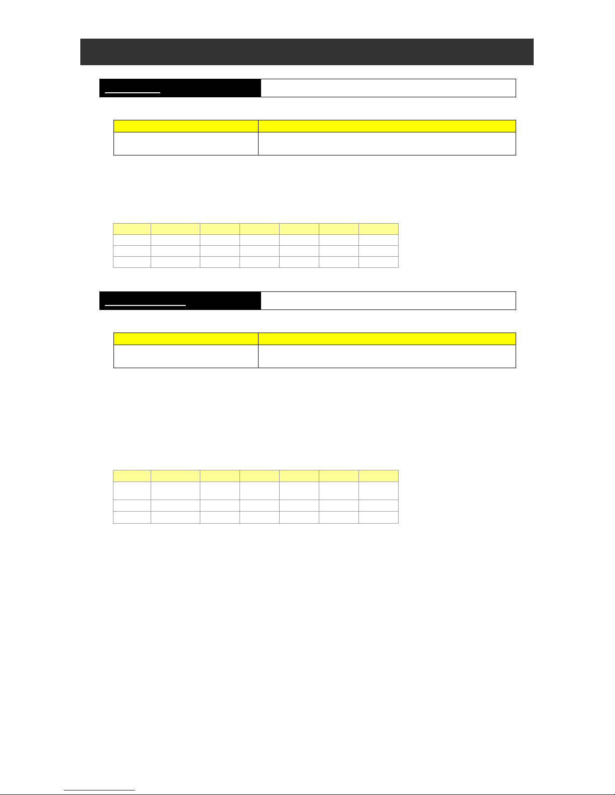
1.3 Specifications
The table below lists the programming-related specifications of the easy sequence function.㩷
Item Specification
Language
s
p
ecification
Programming language Basic-like language
Input device Windows (DOS/V) personal computer (OS:Windows2000,WindowsXP)
Max. program size 1024steps (The internal storage capacity of the inverter is 1024 steps or 6144 bytes.)
Programming support
function (programming
software)
- Editing (on Windows) / - Display (on Windows)
- Program syntax check (on Windows)
- Downloading, uploading, and full clearance of program
Execution format
Execution by interpreter in an execution cycle of 2 ms per instruction
(possible subroutine call with nesting in up to 8 layers)
Input/output-related functions
External input
Contact signal
24 V open-collector input (using intelligent input terminals)
Program run signal input
SJ700/L700/SJ700B : Always assigned to the FW terminal
WJ200 : Assign to the PRG terminal / Always run
Program run signal input
SJ700/L700/SJ700B : Up to 8 terminals (X (00) to X (07))
WJ200 : Up to 8 terminals (X (00) to X (07))
General-purpose analog input
XA (0): 0 to 10 V (O terminal)
XA (1): 4 to 20 mA (OI terminal)
XA (2): 0 to 10 V (O2 terminal) (Only SJ700)
External output
General-purpose output terminal
SJ700/L700/SJ700B : Up to 6 terminals (Y (00) to Y (05))
WJ200 : Up to 3 terminals (Y (00) to Y (02))
General-purpose analog output
YA (0): Assignable to the FM terminal
YA (1): Assignable to the AM terminal
YA (2): Assignable to the AMI terminal (Only SJ700)
Reserved words
Instructions
(1) Program control instructions
- Loop (for) / - Unconditional branching (goto) / - Time control (wait)
- Conditional branching (if then, ifs then, select case, until, and while)
- Subroutine (call, sub) / - Others (entry, end, cont, inc, and dec)
(2) Arithmetic instructions
- Arithmetic operation (+, -, *, /) / - Remainder (mod) / - Substitution (=)
- Absolute value (abs) / - Logic operation (or, and, xor, and not)
(3) Input/output control
- General-purpose input/output (bit input, word input, bit output, and word output)
- Reading of inverter input terminal
(4) Timer control : - Delay operation / - Timer control
(5) Parameter control : - Rewriting of parameters by reselecting code on the operator's display
Number of variables
User-defined variable
U (00) to U (31) (32 variables)
Internal user variable
UL (00) to UL (07) (8 variables)
Set frequency SET-Freq
Acceleration time ACCEL
Deceleration time DECEL
Monitoring variable
FM, Iout, Dir, PID-FB, F-CNV, Tmon, Vout, Power,
RUN-Time, ON-Time, PlsCnt (Only SJ700/L700/SJ700B),
POS, STATUS, DCV, ERR CNT, ERR(1), ERR(2), ERR(3),
ERR(4), ERR(5), and ERR(6)
General-purpose input contact
SJ700/L700/SJ700B : X (00) to X (07) (8 contacts)
WJ200 : X (00) to X (07) (8 contacts)
General-purpose output contact
SJ700/L700/SJ700B : Y (00) to Y (05) (6 contacts)
(including a relay contact output)
WJ200 : Y (00) to Y (02) (3 contacts)
(including a relay contact output)
Internal user contact UB (00) to UB (07) (8 contacts)
Internal timer contact
TD (0) to TD (7) (8 contacts)
Inverter input/output
Specification by code on the remote operator's display
User monitor Umon (00) to Umon (02) (3 variables)
User trip Makes the inverter trip (10 variables)
Chapter 1 Outline of EzSQ
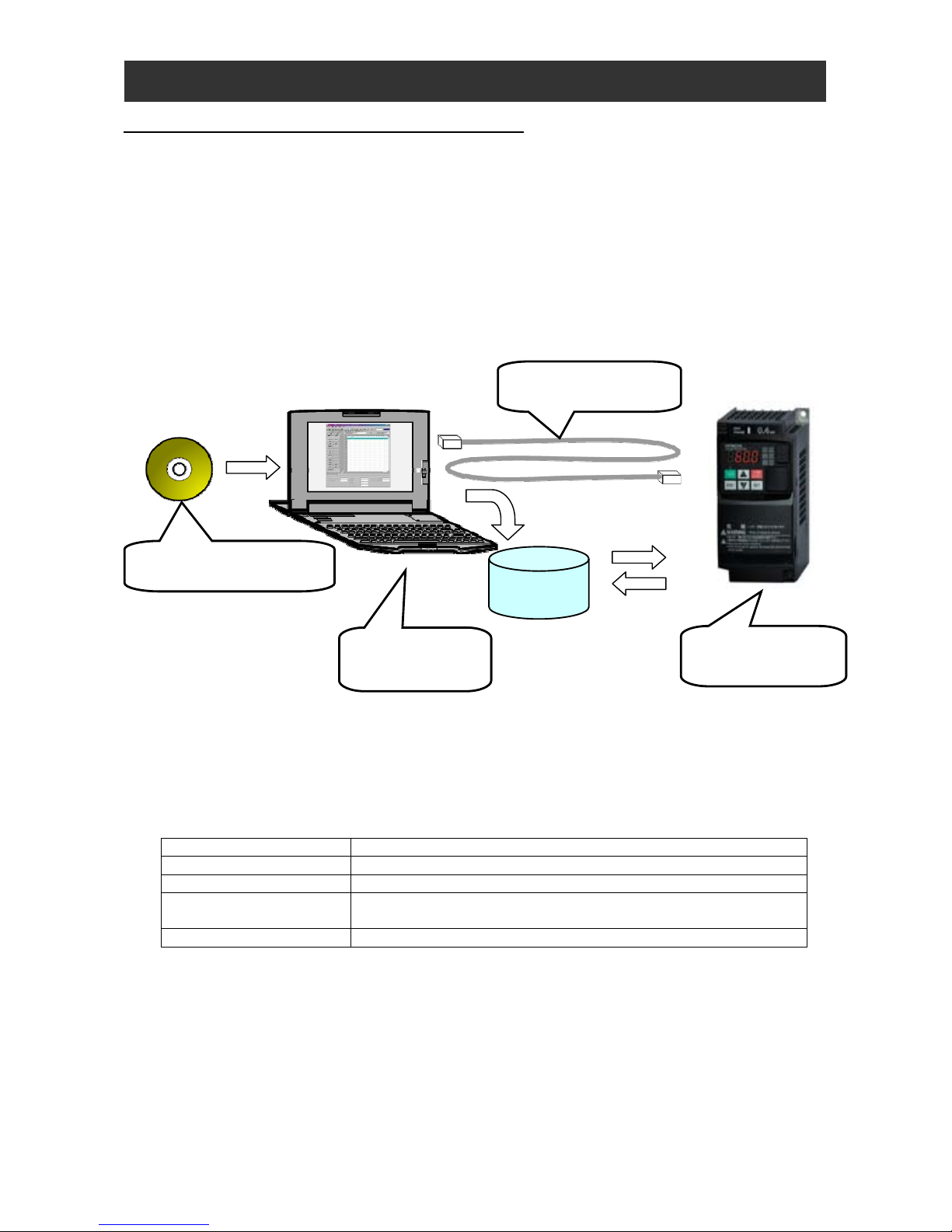
1.4 Preparation and System Configuration
To create user programs with the easy sequence function of the inverter, you must prepare the following devices and
software:
(1) SJ700 or WJ200 or L700 or SJ700B inverter
(2) Personal computer (PC) (Windows system)
(3) Optional programming software ProDriveNext
(4) Optional PC-inverter connection cable
SJ700
Inverter port: Operator-connection port
WJ200
Inverter port: USBminiB connector
The following figure shows the basic system configuration for programming.
1-2
- Install ProDriveNext on your Windows personal computer, and connect the personal computer to the inverter (SJ700
or WJ200 or L700 or SJ700B) via the PC-inverter connection cable.
- After completing these preparations, you can operate ProDriveNext to create a user program and download it to the
inverter.
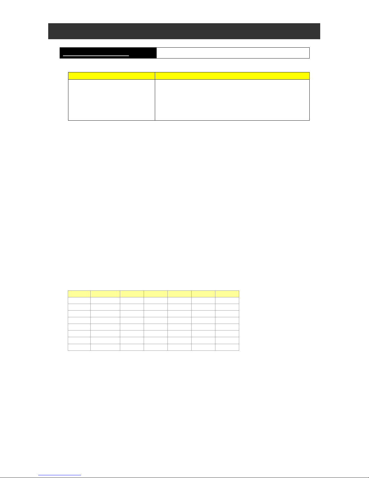
The table below lists the main functions of ProDriveNext. Please refer to the manual of ProDriveNext for use.
Function Description
Programming support Supports the input, editing, saving, reading, and printing of user programs
Compilation Compiles an edited user program
Downloading and uploading Downloads a user program to the inverter
Uploads a user program to from the inverter
Debugging support Monitors program execution, inverter status, and others
Uploading
Optional PC-Inverter
connection cable
SJ700 or WJ200
or L700 or SJ700B
Inverte
r
Optional programming
software ProDriveNext
Commercially
available Windows
personal computer
Installation
Downloading
Programming
User program
1-3
Chapter 1 Outline of EzSQ
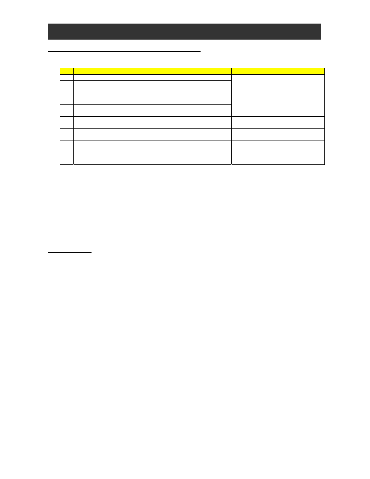
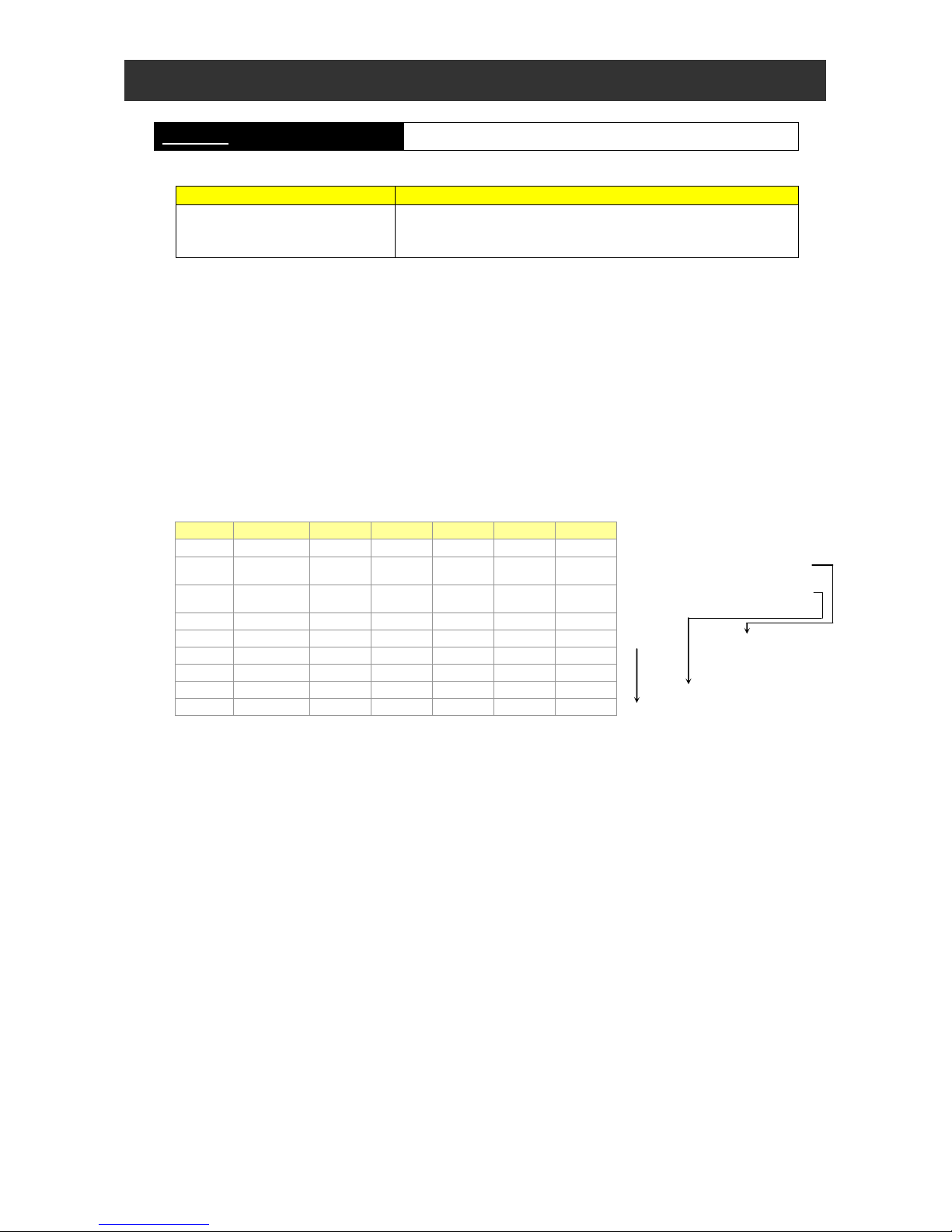
1.5 General Flow of Operation and Setup
A general flow of operations from programming to program execution with the easy sequence function is as follows:
No. Description Remarks
1 Create a user program with the ProDriveNext.
- Please refer to the manual of
ProDriveNext for use.
- For details on the syntax, see
Chapter 4.
2 Compile and format that can be run on inverter.
When a user program is compiled, the codes are checked for
validity. If a syntax error is detected, ProDriveNext stops
compilation and displays an error message.
3 Download the compiled user program to the inverter, and save it in
EEPROM. (*1)
4 Configure the parameters required for the easy sequence function
in the inverter.
Please refer to Chapter 3, “Interface
with the Inverter”.
5 Enable the easy sequence function (set "01" or “02” in parameter
"A017").
6 When A017 = 01, turn on the PRG terminal (FW terminal in SJ700/
L700/ SJ700B) to execute the user program.
When A017 = 02 in WJ200, the user program runs automatically
after turning on the power. (*2)
*1 If the downloaded user program is saved in internal EEPROM of the inverter, you can execute the user program
even after resetting the inverter power. If the downloaded user program is not saved in EEPROM, the user
program will be deleted when the inverter power is fully shut off. You are recommended not to save a created user
program when downloading it to the inverter for debugging purposes. You should save the user program when
downloading it again after debugging.
*2 After having downloaded the user program to the inverter, you can disconnect the inverter from the personal
computer and execute the user program on the inverter alone.
1.6 Notice
(1) The format which can be saved by ProDriveNext is only a CSV file.
(2) The specification is different in SJ700, L700, SJ700B and WJ200.
(3) If RS terminal is turned on, a program counter is reset and the user program runs from the program head. However,
the user program is restarted from the program counter before reset at C102=03.
(4) Do not shut off the power supply of the inverter while writing data in EEPROM by "eepwrt" command.

1-4
Chapter 1 Outline of EzSQ

㩷
Chapter 2 Syntax
This chapter explains the syntax and definitions used for programming.
2.1 Description Format ·················································· 2-1
2.2 List of Instructions ···················································· 2-3
2.3 Program Control Instruc tions ··································· 2-7
2.4 Input/Output Control Instructions ····························· 2-18
2.5 Timer Control Instructions········································ 2-23
2.6 Inverter Control Instructions ···································· 2-27
2.7 Other Reserved Variables ······································· 2-34
2.8 Inverter Montor Variables········································· 2-42

Chapter 2 Syntax
Chapter 2 Syntax
2.1 Description Format
(1) Program Description Format
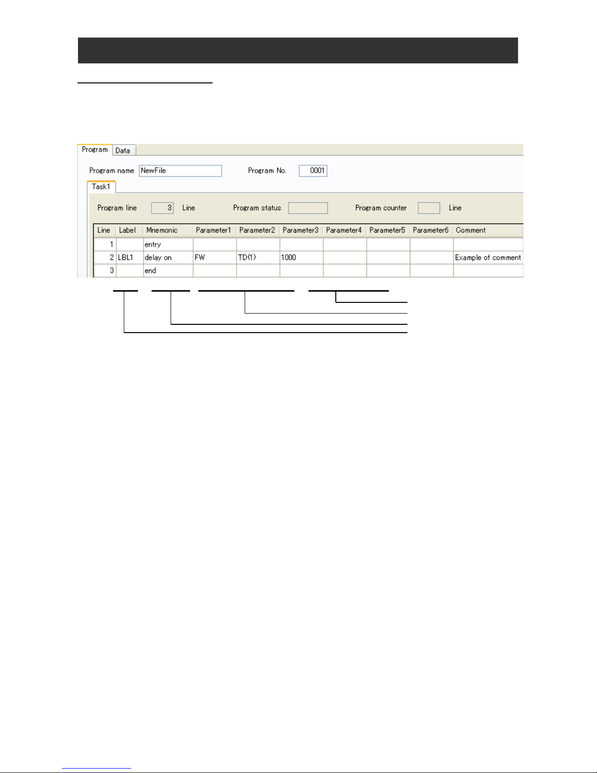
Each line of a program consists of the “Label,” “Mnemonic,” “Parm 1 to 6,” and “Comment” fields. The “Mnemonic” field is used to
describe an instruction word. Some instruction words do not require parameters.㩷
(Example)
LBL1 delay on FW TD (1) 1000 Example of comment
㩷
Comment
㩷
2-1
㩷
㩷
[1] Line : A line is the instruction unit of a program. You can describe one instruction word per line. It takes 2 ms to execute
each line. One instruction corresponds to one step of the program.
Label
Mnemonic instruction code
Parameters
[2] Label : Use the “Label” field to describe, for example, the branch destination for a branch instruction.
[3] Mnemonic : Use the “Mnemonic” field to describe the instruction to be executed. For details on the instructions, see Chapter 5,
“Instruction Words.”
[4] Parameters : Use the “Parameter 1 to 6” fields to describe the arguments required to execute an instruction. Up to six arguments
can be described as required for the instruction word described on the same line.
[5] Comment : Use the “Comment” field to describe a comment on each line.
Note 1 : Please describe the instruction in the line that describes the label. The program might not upload correctly if the
instruction is not described.
Note 2 : The item that can be uploaded are Label, Mnemonic, and Parameters. Comment cannot be uploaded. Moreover,
when the program is uploaded, the label name is changed.
Note 3 : When a program including the line where nothing is described was downloaded and that program is uploaded, the
empty line is deleted. In addition, because program counter monitor (d023) doesn't count the empty line, the
number of Line is not corresponding to the value of the program counter.
Example) When an instruction of the fifth line is executed in a program including the empty line in the second line
and the third line, a value of the program counter is 3.
Chapter 2 Syntax
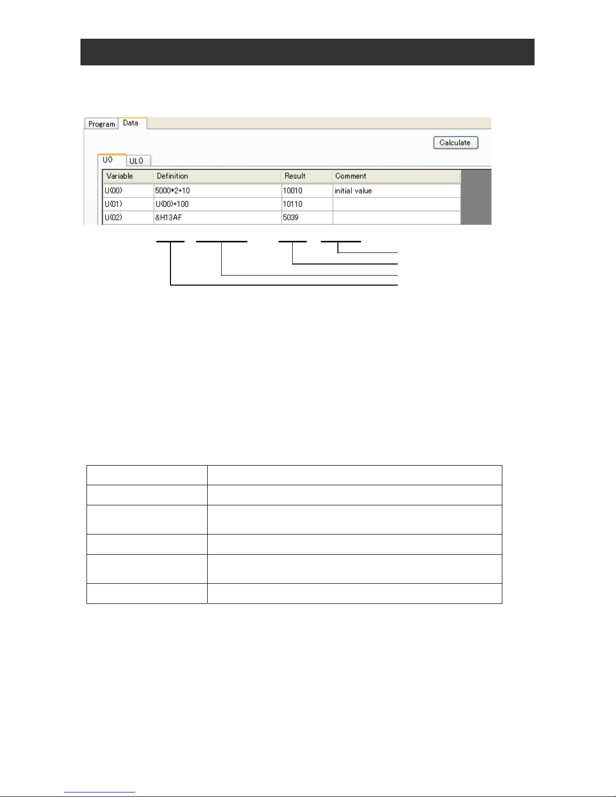
(2) Data Description Format
Each variable is described on a line that consists of the “Variable,” “Define,” “Answer,” and “Comment” fields.
(Example)
㩷
U (00) 5000*2+10 10010 initial value
㩷
Comment
㩷
Calculation result
㩷
Definition expression
㩷
Variable name
[1] Variable : Use the “Variable” field to describe a variable name to be defined.
[2] Definition : Use the “Definition” field to describe a definition expression for a variable. A definition expression can be a variable
name. Clicking the [Calculate] button in the “Data Window” after entering a definition expression starts calculation. (If
the calculation executed for a variable by clicking the [Calculate] button results in a value that is outside the range of
numeric values defined for the variable, the “Data range is invalid!!” message will appear and the “Result” field will
indicate “<Range is invalid.>.”)
[3] Result : The “Result” field displays a calculation result. You cannot rewrite the calculation result.
[4] Comment : You can describe a comment about the variable described on the line.
Note : The item that can be uploaded is only Result. Definition and Comment cannot be uploaded.
(3) Multitasking function
In WJ200 series, two or more programs (a maximum of 5 tasks) can be simultaneously performed by the multitasking function. One
line of each task is executed at 2ms cycle. Please refer to the manual of ProDriveNext for the method of making two or more tasks.
The limitations in multitasking are shown below.
Limitations Description
Subroutine CALL Subroutine CALL between tasks is not made.
Movement to the label It cannot move between tasks to the label by the goto instruction and the if
instruction, etc.
Variables The variables such as user-defined variable U (00) become common by each task.
Timer When plural tasks carry out timer set / timer off for the same timer number, it will not
work normally.
Display of d023 Inverter function cord d023 displays program counter of task 1.
2-2

Chapter 2 Syntax
2-3
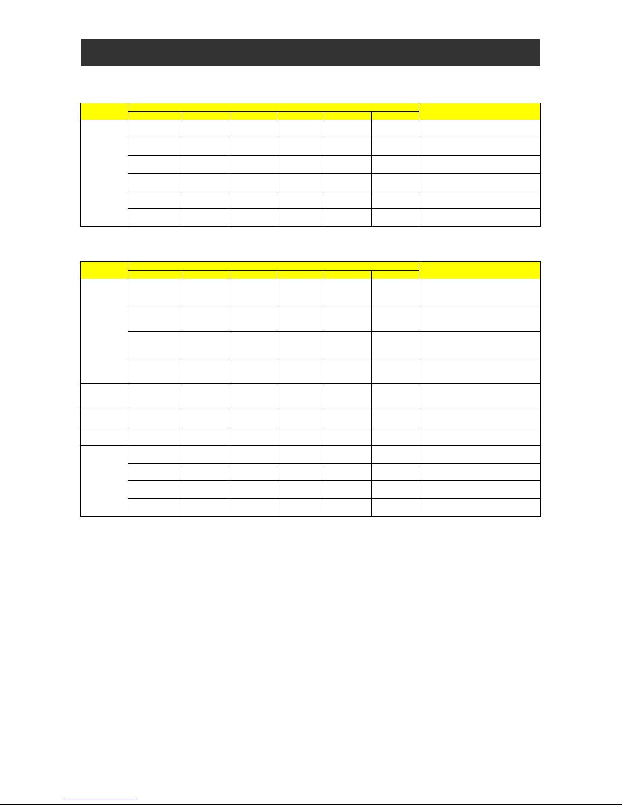
2.2 List of Instructions
This section lists the instructions that can be used in a program.
(1) Program control instructions
Instruction
name
Instruction format
Description
Mnemonic code Parameter 1 Parameter 2 Parameter 3 Parameter 4 Parameter 5
entry
statement
entry
Indicates the beginning of the main
program.
end
Indicates the end of the main program.
sub
statement
sub
<subroutine
name>
Indicates the beginning of a subroutine.
end sub
Indicates the end of a subroutine.
call
statement
call
<subroutine
name>
Branches processing to the subroutine
specified by <subroutine name>.
for loop
statement
for
<variable> <start value> <end value>
<incremental
value>
Executes <instruction set> repeatedly until
<variable> reaches <end value>. Note that
<variable>, which initially contains <start
value>, is incremented by <incremental
value> each time <instruction set> is
executed.
<instruction set>
Indicates the instructions to be executed
repeatedly.
next Ends the “for” loop.
goto
statement
goto <label name>
Branches processing unconditionally to the
step labeled with <label name>.
on trip goto
statement
on trip goto <label name>
Branches processing to the step labeled
with <label name> when the inverter trips.
if statement
if <condition> VJGP <label name>
Branches processing to the step labeled
with <label name> when the <condition> is
met.
structured if
ifs <condition> Starts the structured if statement.
then
Indicates the beginning of instructions to be
executed when <condition> is met.
<instruction set>
Indicates the instructions to be executed
when <condition> is met.
else
Indicates the beginning of instructions to be
executed when <condition> is not met.
<instruction set>
Indicates the instructions to be executed
when <condition> is not met.
end if Ends the structured if statement.
select case
syntax
statement
select
<conditional
variable>
Executes the instructions specified after
“case” when the value of <conditional
variable> is <conditional value>.
case
<conditional
value>
Indicates the conditional value and the
beginning of instructions to be executed.
[case else]
Indicates the beginning of instructions to be
executed when the value of <conditional
variable> is not <conditional value>.
end select
Ends the select case syntax statement.
until loop
statement
until
<condition>
Executes <instruction set> repeatedly until
<condition> is met.
<instruction set>
Indicates the instructions to be executed
while <condition> is not met.
loop Ends the “until” loop.
wait loop
statement
wait ***.**
Waits for “***.**” seconds.
<variable>
Waits for <variable> × 10ms.
<condition> Waits until <condition> is met.
while loop
statement
while
<condition>
Executes <instruction set> while
<condition> is met.
<instruction set>
Indicates the instructions to be executed
while <condition> is met.
wend
Ends the “while” loop.
inc
statement
inc <variable> Increments the value of <variable> by 1.
dec
statement
dec
<variable> Decrements the value of <variable> by 1.
Chapter 2 Syntax
2-4
(2) Conditional expressions
The table below lists the conditional expressions that can be used for the <condition> parameters in program control instructions.
Instruction
name
Instruction format
Description
Mnemonic code Parameter 1 Parameter 2 Parameter 3 Parameter 4 Parameter 5
Comparison
<variable 2 /
constant>
=
<variable 3/
constant>
“True” when <variable 2/constant> is equal
to <variable 3/constant>
<variable 2 /
constant>
<
<variable 3/
constant>
“True” when <variable 2/constant> is less
than <variable 3/constant>
<variable 2 /
constant>
<=
<variable 3/
constant>
“True” when <variable 2/constant> is not
greater than <variable 3/constant>
<variable 2 /
constant>
>
<variable 3/
constant>
“True” when <variable 2/constant> is
greater than <variable 3/constant>
<variable 2 /
constant>
>=
<variable 3/
constant>
“True” when <variable 2/constant> is not
less than <variable 3/constant>
<variable 2 /
constant>
<>
<variable 3/
constant>
“True” when <variable 2/constant> is not
equal to <variable 3/constant>
Note : <variable 1> and <variable 2> can be constants ranging from 0 to 127.
(3) Operational instructions
Instruction
name
Instruction format
Description
Mnemonic code Parameter 1 Parameter 2 Parameter 3 Parameter 4 Parameter 5
Arithmetic
operation
<variable 1> =
<variable 2/
constant>
<variable 3/
constant>
Adds <variable 2/constant> and <variable
3/constant> and assigns the result to
<variable 1>.
<variable 1> =
<variable 2/
constant>
<variable 3/
constant>
Subtracts <variable 3/constant> from
<variable 2/constant> and assigns the
result to <variable 1>.
<variable 1> =
<variable 2/
constant>
<variable 3/
constant>
Multiplies <variable 2/constant> by
<variable 3/constant> and assigns the
result to <variable 1>.
<variable 1> =
<variable 2/
constant>
<variable 3/
constant>
Divides <variable 2/constant> by <variable
3/constant> and assigns the result to
<variable 1>.
Remainder <variable 1> =
<variable 2/
constant>
mod
<variable 3/
constant>
Divides <variable 2/constant> by <variable
3/constant> and assigns the remainder to
<variable 1>.
Absolute
value
<variable 1> = abs
<variable 3/
constant>
Assigns the absolute value of <variable
3/constant> to <variable 1>.
Substitution <variable 1> =
<variable 3/
constant>
Assigns <variable 3/constant> to <variable
1>.
Logic
operation
<variable 1> =
<variable 2/
constant>
or
<variable 3/
constant>
Assigns the OR of <variable 2/constant>
and <variable 3/constant> to <variable 1>.
<variable 1> =
<variable 2/
constant>
and
<variable 3/
constant>
Assigns the AND of <variable 2/constant>
and <variable 3/constant> to <variable 1>.
<variable 1> =
<variable 2/
constant>
xor
<variable 3/
constant>
Assigns the XOR of <variable 2/constant>
and <variable 3/constant> to <variable 1>.
<variable 1> = not
<variable 3/
constant>
Inverts the bits of <variable 3/constant> and
assigns the inverted bits to <variable 1>.
Note 1 : <variable 2> can be a constant ranging from 0 to 127.
Note 2 : <variable 3> can be a constant ranging from 0 to 2
31
-1.

Chapter 2 Syntax
2-5
(4) Input / output control, timer control, and inverter control instructions
Instruction
name
Instruction format
Description
Mnemonic code Parameter 1 Parameter 2 Parameter 3 Parameter 4 Parameter 5
Generalpurpose
contact input
<variable> = X (ii)
Fetches general-purpose contact
information and stores it in <variable>. (0 =
off, 1 = on)
<variable> = Xw
Fetches general-purpose contact
information and stores it as word data in
<variable>.
Generalpurpose
contact
output
Y (ii) =
<variable /
constant)
Outputs bit data to a general-purpose
contact. (0 = off, 1 = on)
Yw =
<variable /
constant)
Outputs word data to a general-purpose
contact.
Inverter
operation
command
<input terminal> =<variable /
constant)
Operates an inverter input terminal. (0 = off,
1 = on)
Inverter
operation
monitoring
<variable> =
<output
terminal>
Fetches information from an inverter output
terminal.
<variable> =
<input
terminal> =
Fetches information from an inverter input
terminal.
Delay
operation
delay on <variable 1> TD (k)
<variable 2/
constant>
Turns on the terminal specified by <variabl e
1> after the time specified by
<variable2/constant> elapses.
delay off <variable 1> TD (k)
<variable 2/
constant>
Turns off the terminal specified by <variable
1> after the time specified by
<variable2/constant> elapses.
Timer control
timer set TD (k)
<variable /
constant)
Sets <variable/constant> in a specified
timer and starts the timer.
timer off TD (k) Stops the specified timer.
Internal user
contact
control
<variable> = UB (ii)
Fetches internal user contact information
and stores it in <variable>. (0 = off, 1 = on)
<variable> = UBw
Fetches internal user contact information
and stores it as word data in <variable>.
UB (ii) =
<variable /
constant)
Outputs bit data to an internal user contact.
(0 = off, 1 = on)
UBw =
<variable /
constant)
Outputs word data to an internal user
contact.
Parameter
change
chg param
<display
code>
<variable /
constant)
Replaces the content of <display code>
with <variable/constant>.
Parameter
reading
mon param
<display
code>
<variable>
Reads the content of <display code> into
<variable>.
Parameter
writing
eepwrt
Stores a data of only one parameter
changed by chg param command that is
issued immediately after the execution of
eeprwrt command to EEPROM. (SJ700/
L700/ SJ700B series doesn't correspond.)
Clock
command
rtcset on <variable>
The clock data is substituted f or six bytes
that make <variable> a head. Moreover,
the clock data is regularly updated. (Only
WJ200 Step2 corresponds.)
rtcset off <variable>
The clock data is substituted f or six bytes
that make <variable> a head. Moreover,
the update of the clock data is stopped.
(Only WJ200 Step2 corresponds.)
Stop
inverter
stop The inverter decelerate and stop the motor
User
monitor
Umon(ii) = <variable>
Displays <variable> on user monitor (ii)
Umon(ii) = <variable1> <operators> <variable2>
Displays the result of operation with
<variable1> and <variable2> on user
monitor (ii)
<variable>= Umon(ii)
Value of user monitor (ii) is read out to
<variable>
User trip trip <variable> Makes the inverter trip
Chapter 2 Syntax
2-6
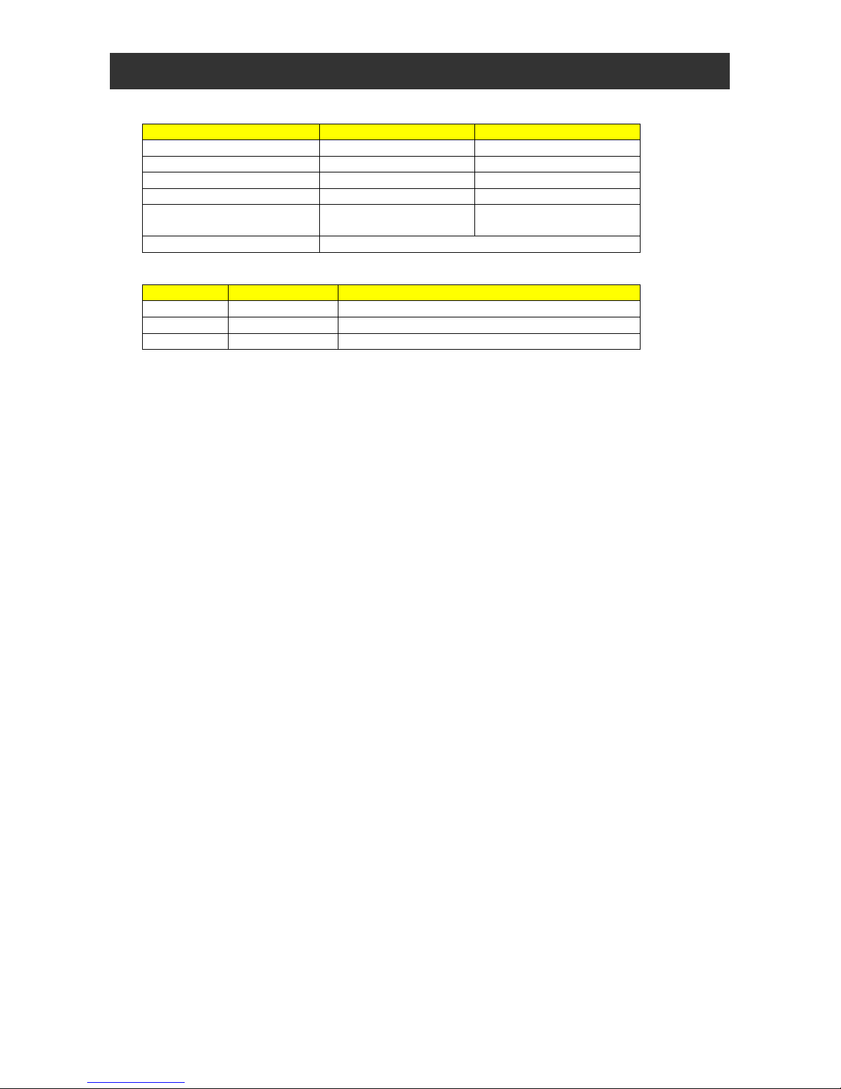
(5) Variables
Type of variable Variable name Range of numeric values
Bit and contact variables FW, X (00), etc. 0, 1 (0: OFF, 1: ON)
User-defined variable U (00) to U (31) 0 to 65535
Internal user variable UL (00) to UL (07) -2147483648 to 2147483647
Frequency setting variable SET-Freq 0 to 40000
Acceleration / deceleration time
setting variable
ACCEL, DECEL 0 to 360000
Monitoring and other variables See Section 2.8, “Inverter Monitor Variables.”
(6) Numeric values㩷
Notation Numeration Remarks
(Omitted) Decimal Decimal number
&H Hexadecimal Hexadecimal number (specifiable only in the “Data Window”)
&B Binary Binary number (specifiable only in the “Data Window”)
Chapter 2 Syntax
2-7
2.3 Program Control Instructions
This section explains the details of program control instructions.
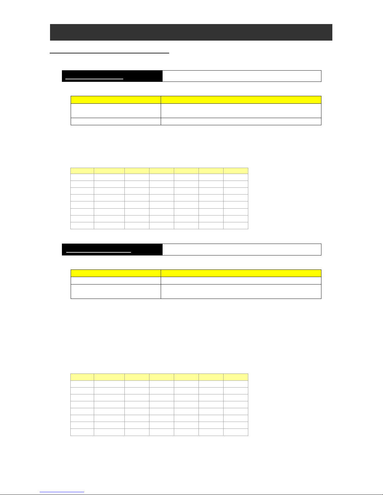
entry and end statements Instructions to start and end the main program
- Format
Format Description
entry
This instruction indicates the beginning of the main program.
(This instruction must be described at the top of the main program.)
end This instruction indicates the end of the main program.
- Explanation
The entry and end statements indicate the beginning and end of the main program, respectively. Each program always
requires these instructions.
- Sample program
Label Mnemonic parameter1 parameter2 parameter3 parameter4 parameter5 㩷
㩷 entry 㩷㩷㩷㩷㩷: The main program begins.
㩷
㩷䋺㩷
㩷㩷㩷㩷㩷
㩷 FW = 1 㩷㩷㩷: Start forward rotation of the motor.
㩷 wait 10.00 㩷㩷㩷㩷: Wait 10 seconds.
㩷 stop 㩷㩷㩷㩷㩷: Stop inverter output.
㩷 wait 10.00 㩷㩷㩷㩷: Wait 10 seconds.
㩷
㩷䋺㩷
㩷㩷㩷㩷㩷
㩷 end 㩷㩷㩷㩷㩷: The main program ends.
sub and end sub statements Instructions to start and end a subroutine
- Format
Format Description
sub <subroutine name> This instruction indicates the beginning of a subroutine.
end sub
This instruction indicates the end of a subroutine.
Control is returned to the calling routine.
- Explanation
The sub and end sub statements indicate the beginning and end of a subroutine, respectively.
<subroutine name> : Specifies the name of a called subroutine. This subroutine name is the first argument (branch
destination) of the call instruction in the calling routine.
Note : Subroutines can be nested in up to eight layers. A subroutine programmed with a structured instruction (i.e.,
sub, for, while, until, select, or ifs) is counted as one nesting layer. Therefore, when a for-next loop statement
is described in a subroutine, there are two nesting layers.
- Sample program
Label Mnemonic parameter1 parameter2 parameter3 parameter4 parameter5
㩷
㩷 sub sub1 㩷㩷㩷㩷: Subroutine "sub1" begins.
㩷
㩷䋺㩷
㩷㩷㩷㩷㩷
㩷 FW = 1 㩷㩷㩷: Start forward rotation of the motor.
㩷 wait 10.00 㩷㩷㩷㩷: Wait 10 seconds.
㩷 stop 㩷㩷㩷㩷㩷: Stop inverter output.
㩷 wait 10.00 㩷㩷㩷㩷: Wait 10 seconds.
㩷
㩷䋺㩷
㩷㩷㩷㩷㩷
㩷 end sub 㩷㩷㩷㩷㩷: Subroutine "sub1" ends.
Chapter 2 Syntax
goto statement Instruction to branch processing unconditionally
- Format
Format Description
goto <label name>
This instruction branches processing unconditionally to the step labeled
with <label name>.
- Explanation
Use this instruction to branch processing unconditionally to the step labeled with <label name>.
<label name> : Specifies the label name of the branch-target step (line).
- Sample program
Label Mnemonic parameter1 parameter2 parameter3 parameter4 parameter5
㩷
㩷 goto LABEL1 㩷㩷㩷㩷: Unconditionally branch to step "LABEL1".
㩷
㩷䋺㩷
㩷㩷㩷㩷㩷
LABEL1 FW= 1 㩷㩷㩷㩷: Branch target
on trip goto statement Instruction to branch processing upon the occurrence of an event
- Format
Format Description
on trip goto <label name>
This instruction branches processing to the step labeled with <label
name> when the inverter trips.
- Explanation
Use this instruction to branch processing to the step labeled with <label name> when the inverter trips.
In the SJ700 Series, when inverter trips without the description of this instruction, the program stops immediately after the
occurrence of inverter trip.
In the WJ200 Series, when the user trip occurs without the description of this instruction, the program stops immediately after
the occurrence of inverter trip.
- Sample program
Label Mnemonic parameter1 parameter2 parameter3 parameter4 parameter5
㩷
㩷 on trip goto LABEL1 㩷㩷
: Branch to step "LABEL1" when the
inverter trips.
㩷
㩷䋺㩷
㩷㩷㩷㩷㩷
LABEL1 Y(00)= 1 㩷㩷㩷㩷: Branch target
2-8
Chapter 2 Syntax
2-9
ifs-then-else-end if statements Structured if instruction
- Format
Format Description
ifs <condition>
[then]
<instruction set 1>
[else]
<instruction set 2>
end if
When <condition> is met, this instruction executes <instruction set 1>
described between “then” and “else.”
When <condition> is not met, this instruction executes <instruction set
2> described between “else” and “end if.”
- Explanation
This instruction executes different sets of instructions according to whether <condition> is met.
When <condition> is met, this instruction executes <instruction set 1>. When <condition> is not met, this instruction
executes <instruction set 2>.
If neither “then <instruction set 1>“ nor “else <instruction set 2>“ is described, the ifs statement jumps to the end if
statement.
<condition> : Specifies a conditional expression among those listed in Section 2.2, “ List of Instructions (2)
Conditional expressions.”
<instruction set 1> : Specifies the instructions to be executed when <condition> is met. The instructions may be described
on two or more lines. The instructions are executed in units of lines in a cycle as explained below.
<instruction set 2> : Specifies the instructions to be executed when <condition> is met. The instructions may be described
on two or more lines. The instructions are executed in units of lines in a cycle as explained below.
- Processing cycle
Note that <condition> is checked in the first cycle, and the first instruction in <instruction set 1> or <instruction set 2> is
executed in the second cycle. In the third cycle, the second instruction <instruction set 1> or <instruction set 2> is executed
or, if no other instruction remains in the instruction set, processing jumps to the end if statement. Therefore, the routine from “ifs”
to “end if” is executed in three cycles when the instruction set contains only one instruction.
Refer to the statement execution sequence indicated by parenthesized numbers in the comment fields of the sample programs
below.
- Sample program
When <condition>
is met
When <condition>
is not met
Label Mnemonic parameter1 parameter2 parameter3 parameter4 parameter5
㩷 ifs X(00) = 1 㩷㩷
䋺 (1)
(1)
㩷 then 㩷㩷㩷㩷㩷
㩷 Y(00)= 1 㩷㩷㩷㩷
䋺 (2)
㩷 Y(01)= 0 㩷㩷㩷㩷
䋺 (3)
㩷 else 㩷㩷㩷㩷㩷
㩷 Y(00)= 0 㩷㩷㩷㩷
䋺
(2)
㩷 Y(01)= 1 㩷㩷㩷㩷
䋺
(3)
㩷 end if 㩷㩷㩷㩷㩷
䋺 (4)
(4)
Chapter 2 Syntax
if statement Instruction to branch processing unconditionally
- Format
Format Description
if <condition> then <label name>
When <condition> is met, processing branches to the step labeled with
<label name>.
When <condition> is not met, processing proceeds to the next step (line).
- Explanation
Use this instruction to branch processing conditionally.
When <condition> is met, processing branches to the step labeled with <label name> described after “then.”
<condition> : Specifies a conditional expression among those listed in Section 2.2, “ List of Instructions (2) Conditional
expressions.”
<label name> : Specifies the label name of the branch-target step (line).
- Processing cycle
Note that <condition> check and branch processing are executed in the same cycle.
Refer to the statement execution sequence indicated by parenthesized numbers in the comment fields of the sample programs
below.
- Sample program
Label Mnemonic parameter1 parameter2 parameter3 parameter4 parameter5
㩷
㩷 Yw= 0 㩷㩷㩷㩷: Turn off terminals Y (00) to Y (05).
㩷
if X(00) = 1 then LABEL1
: (1) When <condition> is met, branch to
step "LABEL1."
㩷
if X(01) = 1 then LABEL2
: (2) When <condition> is met, branch to
step "LABEL2."
㩷 Y(00)= 1 㩷㩷㩷㩷: (3)
㩷 goto LABEL3 㩷㩷㩷㩷: (4) (2)
LABEL1 Y(01)= 1 㩷㩷㩷㩷:(3)
㩷 goto LABEL3 㩷㩷㩷㩷:
LABEL2 Y(02)= 1 㩷㩷㩷㩷:(3)
LABEL3 Y(03)= 1 㩷㩷㩷㩷: (5) (4) (4)
2-10
 Loading...