

MODEL NR 83A
1. PREAUTIONS IN DISASSEMBLY AND REASSEMBLY:
For general reference purposes, the Model NR83A can be said to consist of three major sections: the
Output Section, the Valve Section and the Magazine Section. The descriptions below explain important
points in the disassembly and reassembly of these sections. The circled numbers in the descriptions
correspond to the item numbers in the Parts List and exploded assembly diagram.
[CAUTION] Prior to disassembly/reassembly, ensure without fail that the air hose is disconnected from
the Nailer, compressed air is completely discharged, and all nails are removed.
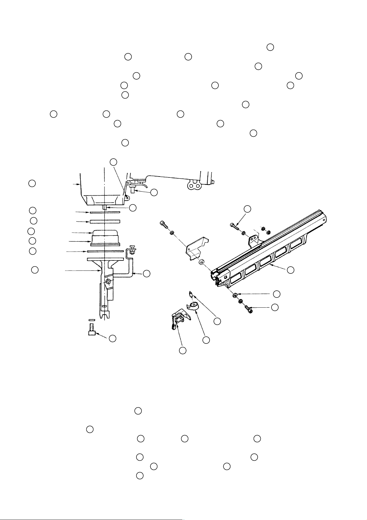
1 -1. Disassembly and Reassembly of the Output Section:
(1) Piston Damper
31
, Packing (A) 32, and Related Parts:
Tools Required:
z#
8 mm, 6 mm and 5 mm Hexagon Bar Wrenches
z#
3 mm Roll Pin Remover
z#
5 mm Spanner
(a) Disassembly:
z#
Loosen the two M5 x 25 Hexagon Socket Hd. Bolts 72 and two M6 x 20 Hexagon Socket
Hd. Bolts
33
which fix the Magazine Base Ass’y 69, and remove the Magazine Base Ass’y
by withdrawing it from the Tail Cover
38
.
−#1#−
Body (B) Ass’y
26
Cylinder O-Ring
28
Cylinder Damper
29
31
Piston Damper
Damper Ring
30
32
Packing (A)
[CAUTION] Prior to loosening the t wo M6 x 20 Hexagon Socket Hd. Bolts 33, shift the
Nail Feeder
remove the front-side M6 x 20 Hexagon Socket Hd. Bolts
Extract the D3 x 30 Roll Pin 47, remove the four M8 x 25 Hexagon Socket Hd. Bolts
z#
which fix the Tail Cover 38, and remove the Tail Cover 38 and Push Lever Ass’y
64
to the Tail Cover 38 side without fail. Also, do not fully
33
.
50
from the Body (B) Ass’y 26.
On completion of the above disassembly procedures, Packing (A) 32, the Piston Damper
z#
31
, Damper Ring 30 and Cylinder Damper 29 can be taken out from the lower portion
of the Body (B) Ass’y
assembled as described in Pare. 1 -1 (2) below, the Cylinder O-Ring
from the Body (B) Ass’y
26
. Please note that if the Cylinder 19 has not been already dis-
28
cannot be removed
26
at this time.
47 D3 x 30 Roll Pin
58
Plunger (B)
14
Piston Ass’y
72 M5 x 25 Hexagon
Socket Bolt
40
Tail Cover
38
40
M7 x 25 Hexason
Socket Hd. Bolts
50
Push Lever Ass’y
66 Ribbon Spring Ass’y
64
Nail Feeder
65
Spring Shaft
37
Washer
33
M6 x 20 Hexagon
Socket Bolts with
Bonding Agent
Fig. 7 Disassembly and Reassembly of the Piston Damper, Packing (A), etc.
(b) Reassembly:
Reassembly can be accomplished by following the disassembly procedures in reverse. However,
special attention should be given to the following items:
Ensure that the Piston Ass’y 14 is positioned so its semicircular groove faces toward the
z#
Magazine side (see Fig. 8 below).
Plunger (B) 58 may drop out during disassembly. Ensure it is properly assembled.
z#
Assemble the Body (B) Ass’y 26, Tail Cover 38, and Magazine Ass’y 81 in the following
z#
manner:
50
I) With the Push Lever Ass’y
Fig. 7, assemble the Tail Cover
Hexagon Socket Hd. Bolts
properly mounted on the Tail Cover 38 as illustrated in
38
to the Body (B) Ass’y 26 with the four M8 x 25
40
, and tighten them to rated torque (see para. 1-4).
69
Magazine Base Ass’y
−#2#−
[CAUTION] Please note that the Push Lever Ass’y 50 cannot be assembled after the
Tail Cover
II) Connect the Push Lever Ass’y
47
.
III) Temporarily attach the Ribbon Spring Ass’y
38
with the M6 x 20 Hexagon Socket Hd. Bolts 33 (please note that this step is not
necessary if the front-side M6 x 20 Hexagon Socket Hd. Bolt
38
has been assembled to Body (B) Ass’y 26.
50
to the Body (B) Ass’y 26 with the D3 x 30 Roll Pin
66
and Nail Feeder 64 to the Tail Cover
33
was only loosened and
not fully removed during reassembly [refer to Fig. 16] ), and assemble the Magazine Base
Ass’y
69
(refer to Para. 1-3- (1)).
[NOTE] Please refer to Para. 1-4 below for appropriate tightening torques for nuts
and bolts.
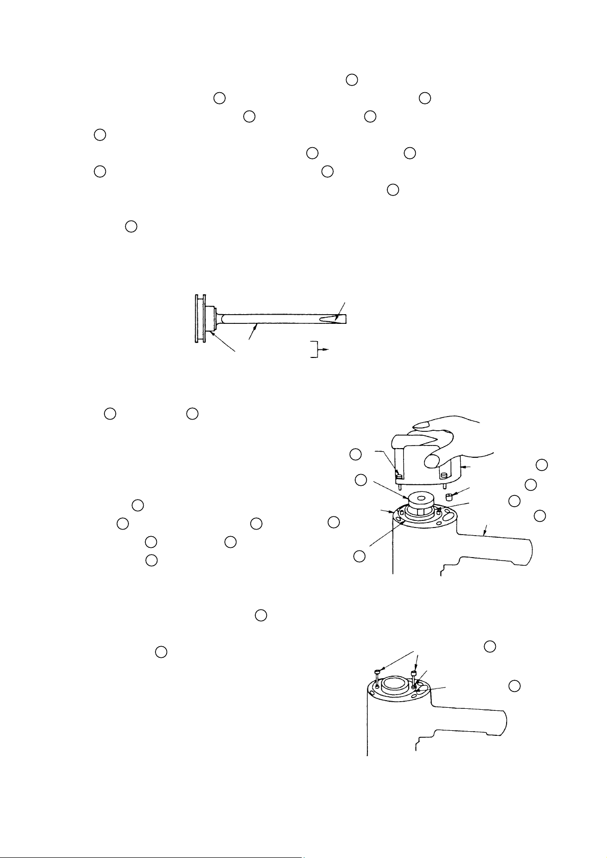
Semi-circle Groove
Drive bit
Piston
Piston Ass’y
Fig. 8 Semi-circle groove of piston ass’y
19
(2) Cylinder
, Piston Ass’y 14 and Related Parts:
Tool Required:
6 mm Hexagonal Bar Wrench
z#
(a) Disassembly:
Loosen the four M6 x 25 Hexagon Socket
z#
Hd. Bolts
Cover
Packing (G)
piston Ass’y
4
, and remove the Exhaust
5
from the Body (B) Ass’y 26.
25
14
(see Fig. 9)
As illustrated in Fig. 10, screw two of the
z#
M6 x 25 Hexagon Socket Hd. Bolts
partially into their matching holes on the
Cylinder Plate
the Cylinder Plate upward while turning
it to remove it from the Body.
, Packing (B) 6, and the
can then be removed.
4
17
. Using the bolts, pull
M6 x 25
Hexagon
Socket Hd.
4
#
Bolt
Piston
14
Ass’y
Packing (B)
6
Cylinder
17
Plate
Fig. 9 Disassembly of Upper
Exhaust Cover
Packing (G)
Cylinder
Body (B) Ass’y
Part of Main Body
M6 x 25 Hexagon
Socket Hd. Bolt
M6 Threaded Hole
Cylinder Plate
#
5
25
19
26
4
17
−#3#−
Fig. 10 Removal of cy linder plate

The Cylinder 19, Cylinder Spring 22, and
other components which constitute the Output
System (see Fig. 11) can then be removed.
As it should be difficult to remove the Cylinder
z#
19
, first remove the Tail Cover 38 as described
in section 1-1-(1), and push the Cylinder upwards and out from below.
(b) Assembly:
Assembly can be accomplished by following the
disassembly procedures in reverse. However, special
attention should be given to the following items:
Ensure that the Piston Ass’y 14 is positioned
z#
so its semicircular groove faces toward the
Magazine (see Fig. 8 above).
Ensure that Packing (G) 25 is properly fitted
z#
to the shape of its matching hole in the Body
(B) Ass’y
26
, properly aligned with the
assembly as shown in Fig. 11, and properly contacts
the base of the Exhaust Piece Ass’y
8
(see
Cylinder Plate
Cylinder
Cylinder Spring
Cylinder Guide
Packing (G)
25
19
22
24
17
Packing (G) Hole (B)
Body (B) Ass’y
26
Fig. 12).
(3) Head Cap Ass’y
12
Related Parts:
Tool Required:
6 mm Hexagonal Bar Wrench
z#
(a) Disassembly;
Remove the Exhaust Cover 5 as described in
z#
section 1-1-(2).
Loosen the three M6 x 45 Hexagon Socket Hd.
z#
Bolts
1
and, as illustrated in Fig. 12, remove
the Head Cap Ass’y
11
, Exhaust Piece Ass’y 8, Packing (C) 9,
and Packing (F)
(b) Reassembly:
Reassembly can be accomplished by following the
disassembly procedures in reverse. However,
special attention should be given to the following
items.
Packing (C) 9 and Packing (F) 7 should be
z#
replaced with new genuine Hitachi parts.
Tighten the M6 x 45 Hexagon Socket Hd. Bolts
z#
1
to rated torque (see Para. 1-4.).
Exhaust Piece Ass’y 8, and
12
Valve Rubber Ass’y
7
.
Fig. 11 Main body output disassembly
M6 x 45 Hexaton
Socket Bolt
Top Cover
Exhaust Cover
Packing (F)
Exhaust
Piece Ass’y
Packing (C)
Valve Rubber
11
Ass’y
1
3
5
7
8
9
Head Cap Ass’y
12
Fig. 12 Disassembly of main body ,
upper part
:
−#4#−

1-2. Dsassembly and Reassembly of the Val ve Section:
Tools Required:
3 mm Roll Pin Remover
z#
Minus-Hd. Screwdriver
z#
(a) Disassembly:
(please refer to Fig. 13)
Remove the Magazine Ass’y 81 as described in
z#
section 1-1- (1).
Remove the Push Lever Ass’y 50 as described in
z#
section 1-1- (1).
With the 3 mm Roll Pin Remover, take out the D3 x 30
z#
Roll Pin
Plunger
Insert the minus-Hd. screwdriver into the groove of
z#
the Trigger Valve Bushing
47
, and remove the Trigger 57, Trigger
63
, and Plunger (B) 58.
62
, and loosen it by
turning it to the left, being careful not to damage the
groove.
After removing the Trigger Valve Bushing 62, pull
z#
down strongly on the Valve Bushing
the Valve Bushing
Plunger Spring
55
, Plunger (A) 54, and the
52
.
55
to remove
Plunger Spring
Plunger (A)
Valve
Bushing
Trigger
Plunger (B)
Plunger (A)
Plunger (B)
52
54
55
57
Valve Plate
Trigger Valve
Bushing
Trigger
Plunger
D3 x 30
Roll Pin
58
Fig. 13 Disassembly of v al ve
54
58
61
62
63
47
(b) Reassembly:
Reassembly can be accomplished by following the
disassembly procedures in revese. However, special
attention should be given to the following items:
Be very careful in handling the Plunger Spring 52,
z#
as it can become twisted very easily.
To prevent the two O-Rings on the outside of t he
z#
Valve Bushing
55
from being damaged when inserted into the Body, carefully apply grease t o t he
Body hole and the outer circumference of the O-Rings
prior to assembly.
(c) Adjustment of the Push Lever Ass’y
The Push Lever Ass’y 50 can be adjusted by loosening
z#
the M5 Nut
Perform adjustment to a point where the resistance of
z#
Plunger (B)
51
and turning the Safety Bolt 48.
58
pushing up Plunger (A) 54 is felt
50
(see Fig. 14):
when the Push Lever Ass’y is raised. At this point, t he
lower end of the Tail Cover
38
should be separated
Safety Bolt
51
50
Tail Cover
38
3.5 ± 0.5 mm
(.138 ± .020 )
M5 Nut
Push Lever
Ass’y
Fig. 14 Push lever assembly adj ustment
48
from the lower end of the Push Lever Ass’y by 3.5 mm
± 0.5 mm (.138"± . 020").
−#5#−

1-3. Disassembly and Reassembly of the Magazine Section:
69
(1) Magazine Base Ass’y
, Nail Feeder 64, Ribbon Spring Ass’y 66, and Related Parts:
Tools Required:
6 mm and 5 mm Hexagon Bar Wrenches
z#
5 mm Spanner
z#
(a) Disassembly:
Shift the Nail Feeder 64 to the Tail Cover 38 side in a state where it is held by the Ribbon
z#
Spring Ass’y
Remove the two M5 x 25 Hexagon Socket Hd. Bolts 72 and the M6 x 20 Hexagon Socket
z#
Hd. Bolt
Loosen the front-side M6 x 20 Hexagon Socket Hd. Bolt 33 (opposite from the Guard
z#
36B
side), and withdraw the Magazine Base Ass’y 69 from the Tail Cover 38. The
Magazine Ass’y
66
.
33
on the Guard
81
, Ribbon Spring Ass’y 66 and related parts can then be disassembled
36B
side.
(see Fig. 15).
Please note that if the front-side M6 x 20 Hexagon Socket Hd. Bolt
and not fully removed, the Nail Feeder
mounted on the Tail Cover
the Magagine Base Ass’y
Spring Shaft
65
38
. This facilitates disassembly and reassembly when only
69
need to be removed.
64
and Ribbon Spring Ass’y 66 can be kept
33 M6 x 20 Hexagon Socket Bolt
36
Guard
33
is only loosened
72
M5 x 25 Hexagon Socket Hd. Bolt
Ribbon Spring Ass’y
Nail Feeder
64
66
69
Magazine Base Ass’y
37 Washer
33 M6 x 20 Hexagon Socket Hd. Bolt
(with Bonding Agent)
Fig. 15 Disassembly / Reassembly of the Magazine Section
−#6#−

(b) Reassembly:
Reassembly can be accomplished by
following the disassembly procedures in
reverse. However, special attention
should be given to the following items.
As illustrated in Fig. 16, temporarily
z#
fix the Ribbon Spring Ass’y 66,
Spring Shaft 65 and Nail Feeder
64
onto the Tail Cover 38 with the
front-side M6 x 20 Hexagon Socket
Hd. Bolt 33, and slide the Magazine
Base Ass’y 69 onto the Tail Cover
38
. Then, secure the assembly by
tightening the M6 x 20 Hexagon
Socket Hd. Bolt 33 on the Guard
36B
side and the two M5 x 25
Hexagon Socket Hd. Bolts 72 to
rated torque (see Para. 1-4).
Finally, loosen the front-side M6 x 20
z#
Hexagon Socket Hd. Bolt 33, shift
the Nail Feeder 64 fully back into
the magazine, ensure the Magazine
Base Ass’y 69 is properly aligned,
and tighten the front-side M6 x 20
Hexagon Socket Hd. Bolt 33 to rated
torque (see Para. 1-4)
(2) Stop Lever 74, Stopper Spring 76, and
Related Parts:
Tools Required:
5 mm and 4 mm Hexagon Bar Wrenches
z#
5 mm and 4 mm Spanners
z#
(a) Disassembly: (see Fig. 17)
After removing the M5 x 45 Hexagon
z#
Socket Hd. Bolt 71 and M4 x 15
Hexagon Socket Hd. Bolt 77, the
parts illustrated in Fig. 17 can be
taken out.
(b) Reassembly: (see Fig. 18)
Reassembly can be accomplished by
following the disassembly procedures in
reverse. However, special attention
should be given to the following items.
As illustrated in Fig. 18, insert the
z#
Collar 75 into the Stop Lever 74,
and mount the Stopper Spring
76
with the M4 x 15 Hexagon Socket Hd.
Bolt 77 (see Para. 1-4 for tightening
torque). At this time, the Stopper
Washer
M6 x 20 Hexagon
Socket Hd. Bolt
Tail Cover
37
33
38
Fig. 16 Mounting of the Nail Feeder
74 Stop Lever
Fig. 17
71 M5 x 45 Hexagon
Socket Hd. Bolt
Fig. 18 Reassembly of the Stop Lever,
Stopper Spring, etc.
70 Sleeve
75
Collar
70 Sleeve
74 Stop Lever
75
76
Stopper Spring
64
Nail Feeder
65 Spring Shaft
66 Ribbon Spring Ass’y
71
M5 x 45 Hexagon
Socket Hd. Bolt
77
M4 x 12 Hexagon
Socket Hd. Bolt
76 Stopper Spring
77
M4 x 12 Hexagon
Socket Hd. Bolt
Collar
−#7#−

Spring 76 must be assembled so that one of its hooked portions is inserted into the Stop
Lever
Magazine Base Ass’y
Fix the Sleeve 70 in position with the M5 x 45 Hexagon Socket Hd. Bolt 71 (see Para.
z#
74
, and the other hooked portion is inserted into the small hole provided on the
69
.
1-4 for tightening torque).
1-4. General Precautions on Reassembly:
Apply grease (Hitachi Motor Grease No. 29, Code No. 930035, is recommended) to the O- Rings and t he
z#
O-Ring sliding portions. When reassembling the O-Rings, be particularly careful not to damage them,
or permit dust or other foreign matter to enter the mechanism.
If the Packings are damaged, replace them without fail and ensure that there is no air leakage after
z#
repair.
Be particularly careful not to permit dust or other foreign matter to enter the Valv e Section.
z#
Coat a small amount of grease (or sliding oil) on the sliding portions of the Nail Feeding Section.
z#
Rated tightening torques for fastening bolts, nuts, screws and t he Pist on Ass’y are as follows:
z#
Bolt / Nut type Rated Tightening Torque
Hexagon Socket Hd. Bolt M8 ................
40
260 ± 20 kg-cm (18.8 ± 1.4 ft-lb)
Hexagon Socket Hd. Bolt M6 ................1, 4,
Hexagon Socket Hd. Bolt M5 ................45, 71,
Hexagon Socket Hd. Bolt M4 ................
Nut M5....................................................
77
51
33
72
100 ± 8 kg-cm (7.2 ± 0.6 ft-lb)
65 ± 5 kg-cm (4.7 ± 0.4 ft-lb)
45 ± 3 kg-cm (3.2 ± 0.2 ft-lb)
35 ± 3 kg-cm (2.5 ± 0.2 ft-lb)
1-5. Inspection and confirmation After Reassembl y or Repair:
Confirm that the Nail Feeder 64 and Stop Lever 74 move smoothly.
z#
Operate the Nailer with an air pressure of 4 kg/cm2 (60 psi), and confirm that there is no abnormal
z#
driving or bending of nails.
With appropriate torque wrenches and / or torque drivers, confirm the correct tightening torque of all
z#
nut, screws and bolts.
−#8#−
 Loading...