

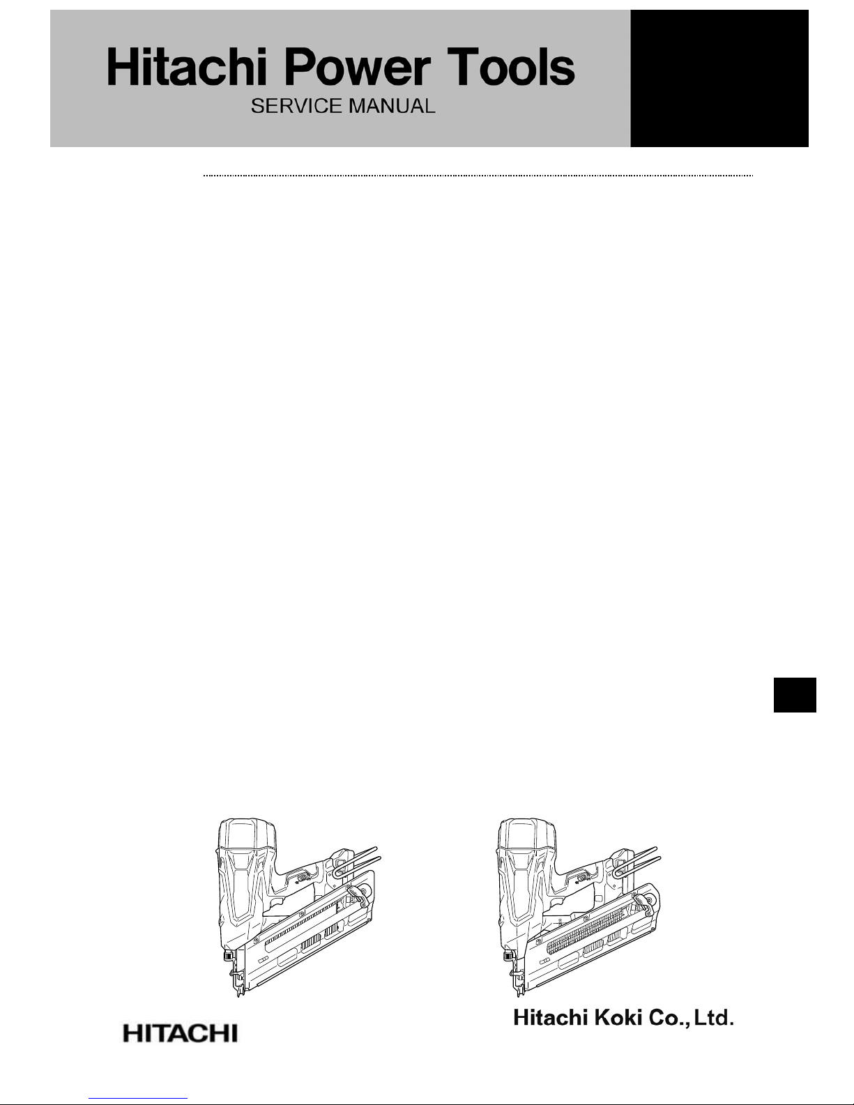
PRODUCT NAME
Hitachi 18 V Cordless Strip Nailer
Models NR 1890DC NR 1890DBCL
NR 1890DR NR 1890DBRL
TROUBLESHOOTING GUIDE --------------------------------------------------------------------------------------- 1
1. Troubleshooting and corrective action --------------------------------------------------------------- 1
2. Corrective action when the orange LED blinks ---------------------------------------------------- 6
3. Maintenance mode --------------------------------------------------------------------------------------- 7
4. Resetting error mode (when the orange LED is blinking) --------------------------------------- 7
REPAIR GUIDE ---------------------------------------------------------------------------------------------------------- 8
1. Precautions on disassembly and reassembly ------------------------------------------------------ 8
• Preparation before disassembly --------------------------------------------------------------------- 8
• Disassembly and reassembly of the magazine section ---------------------------------------- 9
• Disassembly and reassembly of the output section ------------------------------------------ 12
• Replacement of the piston ass'y -------------------------------------------------------------------- 23
• Replacement of sensor (B) --------------------------------------------------------------------------- 26
• Feeding compressed air ----------------------------------------------------------------------------- 27
• Checking after reassembly ------------------------------------------------------------------------- 29
• Tightening torque ------------------------------------------------------------------------------------- 30
• Connecting diagram ---------------------------------------------------------------------------------- 31
STANDARD REPAIR TIME (UNIT) SCHEDULES ------------------------------------------------------------- 32
CONTENTS
CONFIDENTIAL
NR 1890DC: K858
NR 1890DBCL:
NR 1890DR: K859
NR 1890DBRL:
Jul. 2017
NR 1890DR
NR 1890DC
N
Page
Overseas Sales Division
-1-
1. Troubleshooting and corrective action
Problem
Possible cause
(*: Most common cause)
Inspection method Corrective action
1.
Nails
cannot be
driven.
<Nails>
• Magazine is not loaded with
specified Hitachi genuine nails.
• Magazine is loaded with
abnormal nails (e.g., bent nails,
abnormal collation)
• Check whether the
magazine is correctly
loaded with specified nails.
• Use specified nails.
• Remove abnormal
nails and load the
nailer with proper
nails.
• Worn-out piston tip • Check whether the piston
tip is excessively worn.
• Replace defective
parts. See page 23.
• Piston trouble • Check the piston for any
trouble (e.g., deformation,
burring, break).
• Replace defective
parts. See page 23.
<Magazine section>
• Nail feeder trouble (deformation,
burring, break)
• Worn-out nail rail or magazine
plate
• Check the nail feed section
for any trouble (e.g.,
burring, deformation,
break, excessive wear).
• Remove burring.
• Correct the deformed
portion.
• Replace defective
parts.
• Nail guide groove of blade guide
(B) too narrow or wide
• Nail guide groove trouble
(protrusion or burring) of blade
guide (B)
• Step in the nail shank guide
groove between blade guide (B)
and magazine
• Nail guide groove of the
magazine too narrow or wide
• Nail guide groove trouble
(deformation or burring) of the
magazine
• Load nails in the nailer and
make sure the nailer works
normally.
* Unwanted objects (e.g., dust,
wood dust, adhesives) in the nail
guide groove of blade guide (B),
magazine and nail feeder
• Load nails in the nailer and
make sure the nailer works
normally.
• Remove unwanted
objects (e.g., dust,
wood dust,
adhesives).
• Loose bolts of the output section
and the magazine section
—
• Tighten the bolts at the
specified torque.
• Nail feeding trouble • Check the nail feeder slide
surface for dust.
• Check the nail feeder slide
surface for deformation.
• Check the ribbon spring for
damage.
• Replace defective
parts.
• No compressed air in the nailer
• Compressed air leak
• Fill up the nailer with
compressed air, leave the
nailer still for one day, and
then check the nailing
work.
• Check the sealing surfaces,
X-rings, and O-rings inside
the cylinder, piston,
chamber cover, and
chamber base for flaws,
unwanted objects, and
other failures.
• Supply compressed
air.
• Disassemble the nailer
and clean the
chamber, piston, and
their vicinity.
• Replace the sealing
parts.
TROUBLESHOOTING GUIDE
-2-
Problem
Possible cause
(*: Most common cause)
Inspection method Corrective action
2.
Nails are
driven but
bent.
*• Worn-out piston tip
*• Broken or worn-out blade
rack
• Check the piston tip for
excessive wear.
• Check the blade rack for
break or wear.
• Replace defective
parts. See page 23.
• Nails are not completely fed
into the injection port.
• Unspecified nails are used.
• Check whether the
magazine is correctly loaded
with specified nails.
• Use specified nails.
• Remove abnormal
nails and load the
nailer with proper
nails.
• Wood material too hard to be
nailed
• Drive nails into soft wood
and check whether the
driven nails are bent.
• This nailer is not for
hard wood.
• Deformed output section • Check the tips of the
pushing lever and blade
guide for warp, deformation
and excessive wear.
• Replace defective
parts.
3.
Nails
cannot be
driven into
the
workpiece
completely:
the heads
cannot be
made flush.
• Worn-out piston tip • Check the piston tip for
excessive wear.
• Replace defective
parts. See page 23.
*• Worn-out piston rack • Check the piston rack for
excessive wear.
• Replace defective
parts. See page 23.
• Inadequate adjuster control • Set the adjuster to nail
deeper and then nail again.
• Set the adjuster
properly.
• Wood material too hard to be
nailed
• Drive nails into soft wood
and check whether the nail
heads are lifted.
• This nailer is not for
hard wood.
• Weak thrusting force against
wood to be nailed
• Firmly thrust the nailer
against wood to be nailed
and start nailing. Check
whether the nail heads are
still lifted.
• Follow the nailer
operation guide.
• Deformed output section • Check the nail guide groove
of the pushing lever and
blade guide for any trouble
(e.g., deformation,
excessive wear, burrs).
• Replace defective
parts.
• Insufficient grease on the
cylinder and piston section
• Check the greasing
condition of the cylinder and
piston section.
• Replenish grease.
• No compressed air in the
nailer
• Compressed air leak
• Fill up the nailer with
compressed air, leave the
nailer still for one day, and
then check the nailing work.
• Check the sealing surfaces,
X-rings, and O-rings inside
the cylinder, piston,
chamber cover, and
chamber base for flaws,
unwanted objects, and other
failures.
• Supply compressed
air.
• Disassemble the
nailer and clean the
chamber, piston, and
their vicinity.
• Replace the sealing
parts.
4.
Nails jam.
*• Abnormal nails are used
(e.g., bent nails, abnormal
collation)
• Nails are not completely fed
into the injection port.
• Check whether the
magazine is correctly loaded
with specified nails.
• Use specified nails.
• Remove abnormal
nails and load the
nailer with proper
nails.
• Worn-out piston tip • Check whether the piston tip
is excessively worn.
• Replace defective
parts. See page 23.
• Wood material too hard to be
nailed
• Drive nails into soft wood
and check whether nails
jam.
• This nailer is not for
hard wood.
-3-
Problem
Possible cause
(*: Most common cause)
Inspection method Corrective action
4.
Nails jam.
• Piston slide surface trouble
(e.g., galling, break)
• Check the surfaces on
which the piston slides
(blade guides (A) and (B)
and pushing levers (A)
and (B)).
• Replace defective
parts.
<Magazine section>
• Nail feeder trouble (e.g.,
deformation, burring, break)
• Check the nail feed section
for any trouble (e.g.,
burring, deformation,
break, excessive wear).
• Remove burring.
• Correct the deformed
portion.
• Replace defective
parts.
• Nail guide groove of the blade
guide (B) too narrow or wide
• Nail guide groove trouble (e.g.,
protrusion, burrs, excessive
wear) of blade guide (B)
• Nail guide groove of the
magazine too narrow or wide
• Nail guide section trouble (e.g.,
deformation, burrs) of the
magazine
• Load nails in the nailer and
check that the nailer works
normally.
• Remove burring.
• Replace defective
parts.
• Unwanted objects (e.g., dust,
wood dust, adhesives) in the
nail guide groove of the
magazine and nail feeder
• Load nails in the nailer and
check that the nailer works
normally.
• Remove unwanted
objects (e.g., dust,
wood dust, adhesives).
• Deformed output section • Check pushing lever (A)
and blade guides (A) and
(B) for deformation,
excessive wear, and burrs.
• Replace defective
parts.
• Misaligned assembly of blade
guide (B) and magazine
• Set Hitachi genuine nails
in the nailer and lightly
push them against the
magazine. Make sure the
nail tips closely touch the
nail guide surface of blade
guide (B).
(See "Disassembly and
reassembly of the
magazine section.")
• Reassemble blade
guide (B). See page 11.
• Loose bolts of the output
section and magazine section
―
• Tighten the bolts at the
specified torque.
5.
Nailing
started by
single
triggering.
*• Malfunction caused by
unwanted objects (e.g.,
adhesive, dust) near pushing
lever (A), (B) or blade guide
(A) or by deformation of the
lever or blade guide
• Check that pushing lever
(A) moves smoothly (in a
body).
• Clean the pushing lever
and the blade guide.
Then apply oil to them.
• Replace defective
parts.
• Broken or worn-out pushing
lever spring (B)
• Check the spring for any
trouble.
• Replace defective
parts.
-4-
Problem
Possible cause
(*: Most common cause)
Inspection method Corrective action
6.
No nailing
operation
without
motor
rotation
sound.
• Dry-fire lockout mechanism
is activated.
• Count the number of
remaining nails. There
should be 9 or more
remaining nails.
• Load nails.
*• Wire-related trouble of
wiring, switch cable (A), and
sensor (B)
• Check whether the wires and
sensor (B) are firmly
soldered.
• Check whether the rotor
emits a parching smell.
• Check the conductivity of the
switch and microswitch by
using a multimeter.
[Checking procedure]
(1) When switch cable (A) is
not defective:
• Set the switch to OFF and
apply tester probes to the
points shown in the figure
below. Make sure the
terminals are not electrically
connected.
• Set the switch to ON and
apply tester probes to the
points shown in the figure
below. Make sure the
terminals are electrically
connected.
(2) When the microswitch is
not defective:
• Set the switch to ON and
apply tester probes to the
points shown in the figure
below. Make sure the
contacts are electrically
connected.
• Set the switch to OFF and
apply tester probes to the
points shown in the figure
below. Make sure the
contacts are not electrically
connected.
• Firmly resolder the
disconnected wires.
• Replace defective
parts.
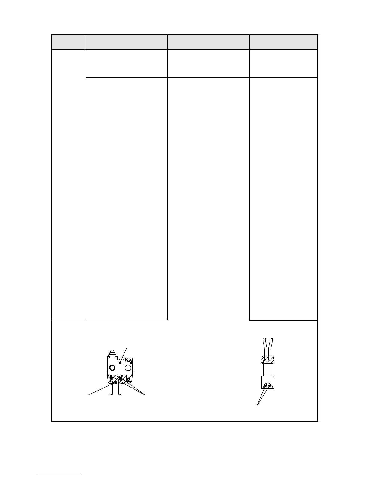
Microswitch
Silicone
Apply multimeter probes here.
NOTE: Remove the silicone a little and apply the
multimeter probes to the exposed terminal metal.
Apply multimeter probes here.
(1) (2)
-5-
Problem
Possible cause
(*: Most common cause)
Inspection method Corrective action
7.
No nailing
operation
with the
orange LED
blinking.
*See page 6.
*• Broken movable part that
disabled nailing work.
• Check the movable part for
any trouble (e.g., deformation,
break, excessive wear).
• Replace defective
parts.
• Disconnected wiring and
stator
• Check the wires and sensor
assemblies for breaks or
disconnection.
• Check the conductivity of the
stator.
• Replace defective
parts.
*• Power transmission
failure due to broken
gears
• Check that the gear turns
smoothly. See page 18.
• Check the gear box ass'y for
breaks.
• Replace defective
parts.
• Sensor (C) trouble • Visually check the sensor
wires for breaks.
• Replace defective
parts.
• Excessively charged
compressed air
• Check the LED lighting
pattern.
• Move the piston down
to the bottom dead
point. Discharge the
compressed air. Use
the reduction valve
set to feed
compressed air
again. See pages 27
to 28.
8.
No nailing
operation
with the red 2
LEDs blinking
*• Overheat protector is
activated.
• Cool the nailer body and
check the nailing work.
―
*• Overcool protector is
activated
• Warm the nailer body and
check the nailing work.
―
9.
No nailing
operation
with the red
LED blinking
*• Low battery voltage • Use a fully charged battery
and check the nailing work
again.
• Charge or replace the
battery.
Red LED Red LED
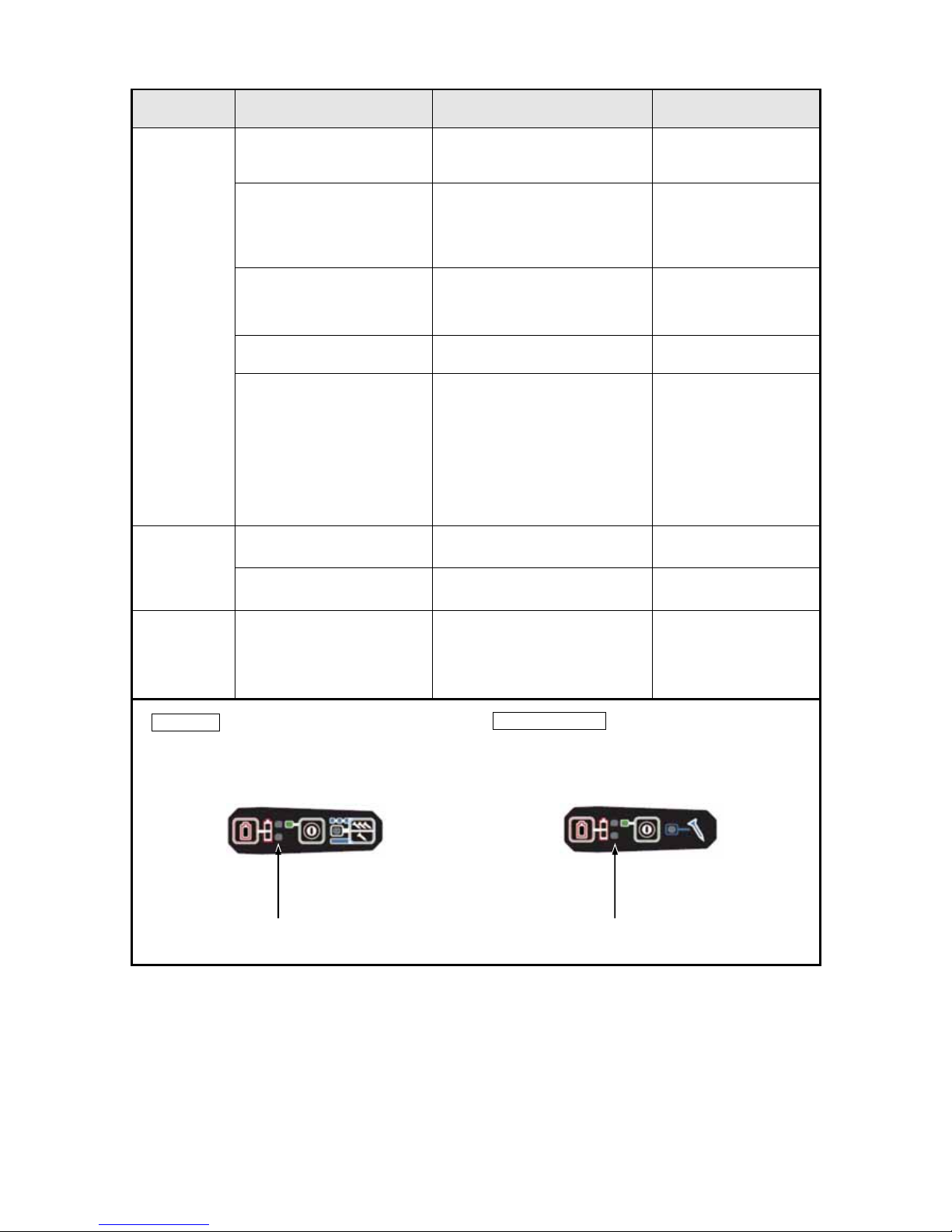
For others
Select the nailing operation mode.
(Full sequential actuation/Contact actuation)
For New Zealand
Select the nailing operation mode.
(Contact actuation only)
-6-
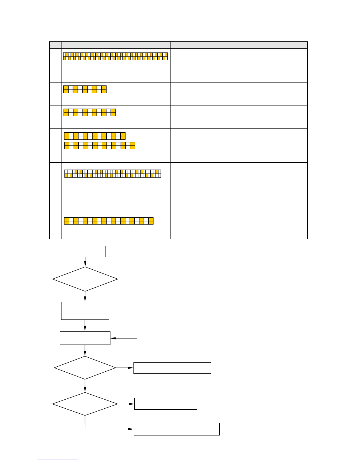
Power ON*1
Reset the error.
(See page 7.)
Pull the trigger.*3
See No. 4 in the table.
See No. 3 and 6 in the table.
See No. 1, 2, and 5 in the table.
2. Corrective action when the orange LED blinks
No. Orange LED lighting pattern Possible cause Corrective action
1 Power switch is automatically turned off after
about 10 seconds.
• Reversed magnet polarity
of position detector
• Sensor (C) failure or
disconnection
• Failure of one-way clutch
in gear box
• Replace defective parts.
2
Power switch is automatically turned off after
blinking 5 times (about 5 seconds).
• Idle by broken gear • Replace defective parts.
3
Power switch is automatically turned off after
blinking 6 times (about 6 seconds).
• Broken wiring • Replace defective parts.
4
Power switch is automatically turned off after
blinking 7 to 8 times (about 7 to 8 seconds).
• Lock by broken gear
• Lock by worn-out piston
rack
• Lock by broken piston
bumper
• Broken wiring
• Replace defective parts.
5
Power switch is automatically turned off after
about 9 seconds.
• Excessively charged
compressed air
• Deformed or broken
moving parts
• Moving parts are out of
grease.
• Replace defective parts.
• Move the piston down to the
bottom dead point. Discharge
the compressed air. Use the
reduction valve set to feed
compressed air again.
• Replace moving parts.
• Lubricate the moving parts
with grease.
6
Power switch is automatically turned off after
blinking 10 times (about 10 seconds).
• Broken wiring • Replace defective parts.
*1: Do not press the pushing lever and/or
pull the trigger during the process of
turning the power switch ON. Doing so
will prevent the power switch from
turning ON.
*2: LED of battery indicator
*3: Press the pushing lever against the
wood before pulling the trigger.
Does the
motor run?
No
Does the orange
LED*
2
blink?
Yes
Does the
piston move?
No
Yes
Yes
No
-7-
Fig. 2
Fig. 1
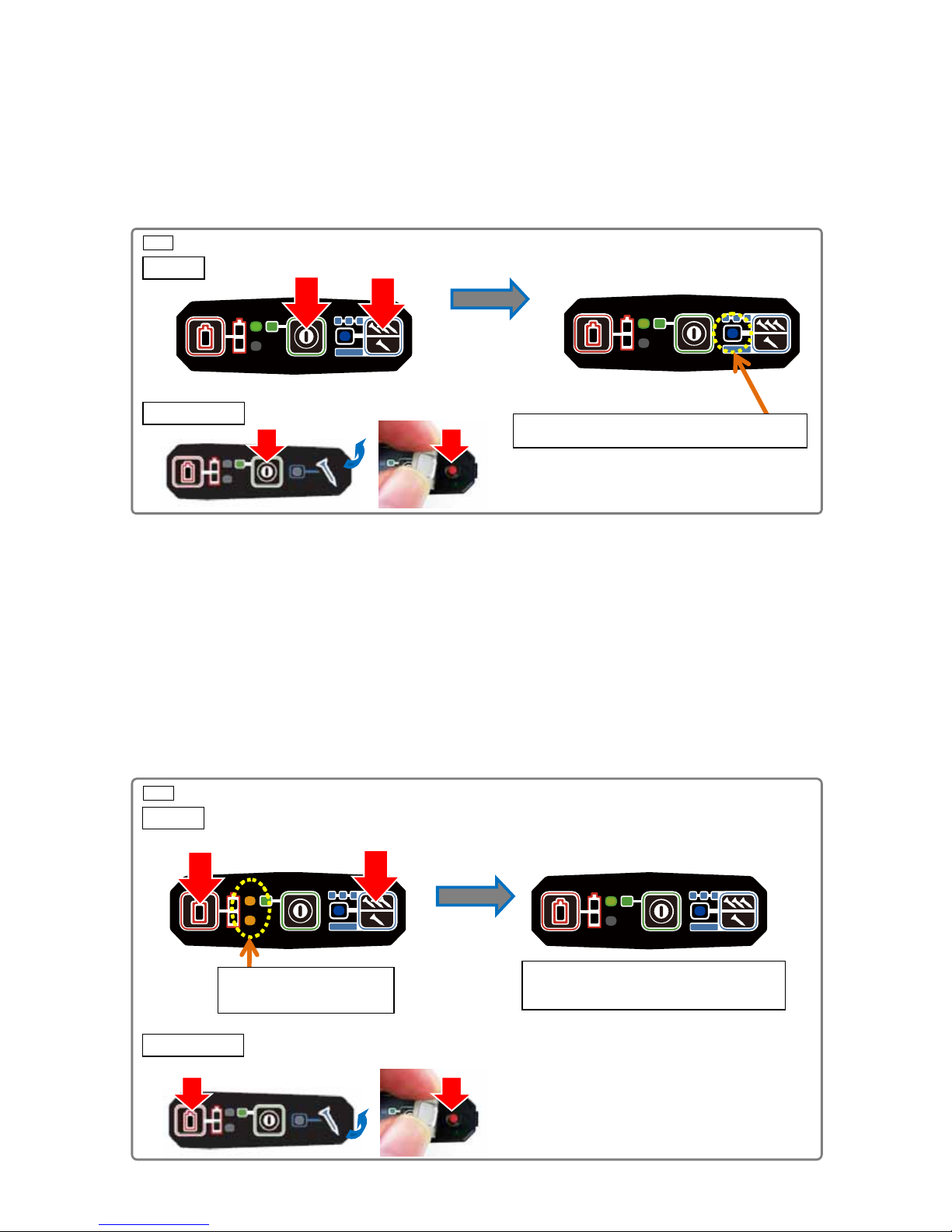
3. Maintenance mode
Maintenance mode is used to move the piston down to the bottom dead point in preparation for feeding
compressed air or overhauling the nailer. To set MAINTENANCE mode, hold down both the nailing
operation switch* and the power switch on the operation panel for at least five seconds.
*: The nailing operation switch is not provided for the products intended for New Zealand. Peel back the
operation panel and press the inside button (red).
Indication: Indicated by the blue LED on the operation panel blinking (at intervals of 0.5 second).
Be careful not to mistake the blinking for contact actuation mode (at intervals of 1.0 second).
Function: Starts the motor when the pushing lever is pressed against wood and the trigger is pulled.
Stops the motor when detecting two motor rotations.
4. Resetting error mode (when the orange LED is blinking)
Error indication: Indicated by the orange battery level indicators blinking (at intervals of 0.5 second).
The power indicator turns off automatically 10 seconds later.
To reset the mode: Hold down both the battery indicator switch and the nailing operation switch for at least
five seconds.
5 seconds later
Full sequential actuation mode is set.
(The blue LED goes on.)
Push
Push
5 seconds later
Push
Push
Orange LED blinking
(
at intervals of 0.5 sec.)
Blue LED blinking (at intervals of 0.5 sec.)
Push Push
Push Push
For others
For New Zealand
For others
For New Zealand
-8-
Fig. 3
The following describes the most essential precautions on disassembly and reassembly of the nailers.
The cordless strip nailer Models NR 1890DC, NR 1890DBCL, NR 1890DR, and NR 1890DBRL mainly
consist of two sections: the output section and the magazine section.
1. Precautions on disassembly and reassembly
[Bold] numbers in the description below correspond to the item numbers in the parts list and exploded
assembly diagram for the Models NR 1890DC and NR 1890DBCL, and (Bold) numbers to those for the
Models NR 1890DR and NR 1890DBRL.
WARNING: Always remove the battery from the main body before starting repair or maintenance
work. Because the tool is cordless, inadvertently activating the switch with the battery
left in the main body will start the motor rotating unexpectedly, and could cause serious
injury.
1. Removal of the hook
Remove the Hook [57](57) by removing the Low Head Hex. Socket Bolts M4 x 8 [58](58) for easy
disassembly work, although disassembly can be done without removing the Hook [57](57).
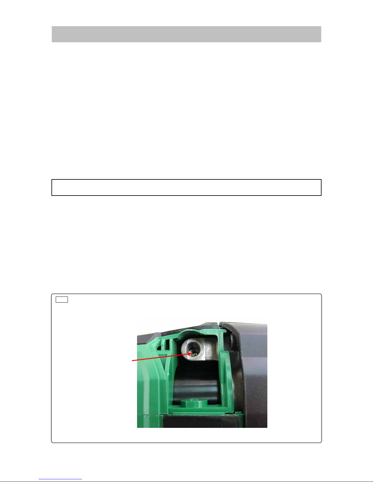
2. Removal of housing (C)
• When the nailer is enabled to nail, set MAINTENANCE mode and move the Piston Ass'y [15](15) down to
the bottom dead point referring to "Feeding compressed air" on page 27.
• Remove the Tapping Screw D4 x 20 [44](44) and remove Housing (C) [45](45).
• Remove the Charge Cap [8](8) by using a hexagonal socket wrench.
• Push the valve core to release compressed air as shown below.
REPAIR GUIDE
Preparation before disassembly
Val v e cor e
-9-
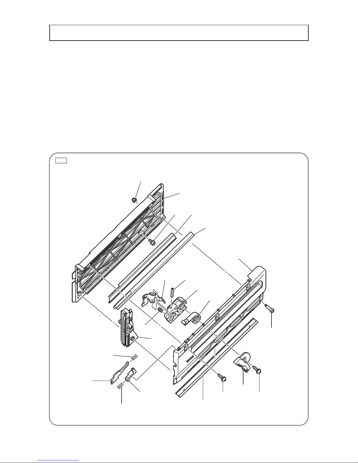
Fig. 4 • Models NR 1890DC and NR 1890DBCL
1. Disassembly
(1) Models NR 1890DC and NR 1890DBCL
• Remove the Nylock Bolt M5 [85] that fastens the magazine ass'y to the Housing Set [46] and two Nylock
Bolts M5 x 22 [34] that fasten the magazine ass'y to the Nose [17].
• Remove the three Tapping Screws D4 x 16 [91], Cap Nut M3 [81], and Step Bolt M3 [89].
• Remove the Magazine Guard [90] from the magazine ass'y and remove Magazine Cover (B) [84] from
Magazine Cover (A) [88]. Then remove Blade Guide (B) [76].
• Remove the Tapping Screw D5 x 20 [93] that fastens Magazine Cover (A) [88] to Nail Feeder (B) [79].
Then remove the Feeder Knob [92] and Ribbon Spring [80].
• Remove Pushing Lever Stopper (A) [72], Pushing Lever Stopper (B) [74], and two Springs [73] from
Magazine Cover (A) [88].
• Remove the Nail Rail [87] from Magazine Cover (B) [84] and remove the Magazine Plate [87].
[81]
[84]
[85]
[86]
[87]
[88]
[89]
[93]
[91]
[90]
[74]
[72]
[73]
[76]
[80]
[79]
[78]
[77]
[75]
[93]
Disassembly and reassembly of the magazine section
[73]
-10-
Fig. 5 • Models NR 1890DC and NR 1890DBRL
(2) Models NR 1890DR and NR 1890DBRL
• Remove the Nylock Bolt M5 x 18 (86) that fastens the magazine ass'y to the Housing Set (46) and two
Nylock Bolts M5 x 22 (34) that fastens the magazine ass'y to the Nose (17).
• Remove the three Tapping Screws D4 x 16 (91), Cap Nut M3 (81), and Step Bolt M3 (89).
• Remove the Magazine Guard (90) from the magazine ass'y and remove Magazine Cover (B) (84) from
Magazine Cover (A) (88). Then remove Blade Guide (B) (76).
• Remove the Tapping Screw D5 x 20 (93) that fastens Magazine Cover (A) (88) to Nail Feeder (B) (79).
Then remove the Feeder Knob (92) and Ribbon Spring (80).
• Remove Pushing Lever Stopper (A) (72), Pushing Lever Stopper (B) (74), and two Springs (73) from
Magazine Cover (A) (88).
• Remove Nail Rail (C) (87) from Magazine Cover (B) (84) and remove the Magazine Plate (85).
(81)
(84)
(85)
(86)
(87)
(88)
(78)
(79)
(80)
(77)
(89)
(93)
(92)
(91) (90)
(73)
(72)
(73)
(74)
(75)
(76)
-11-
Fig. 7
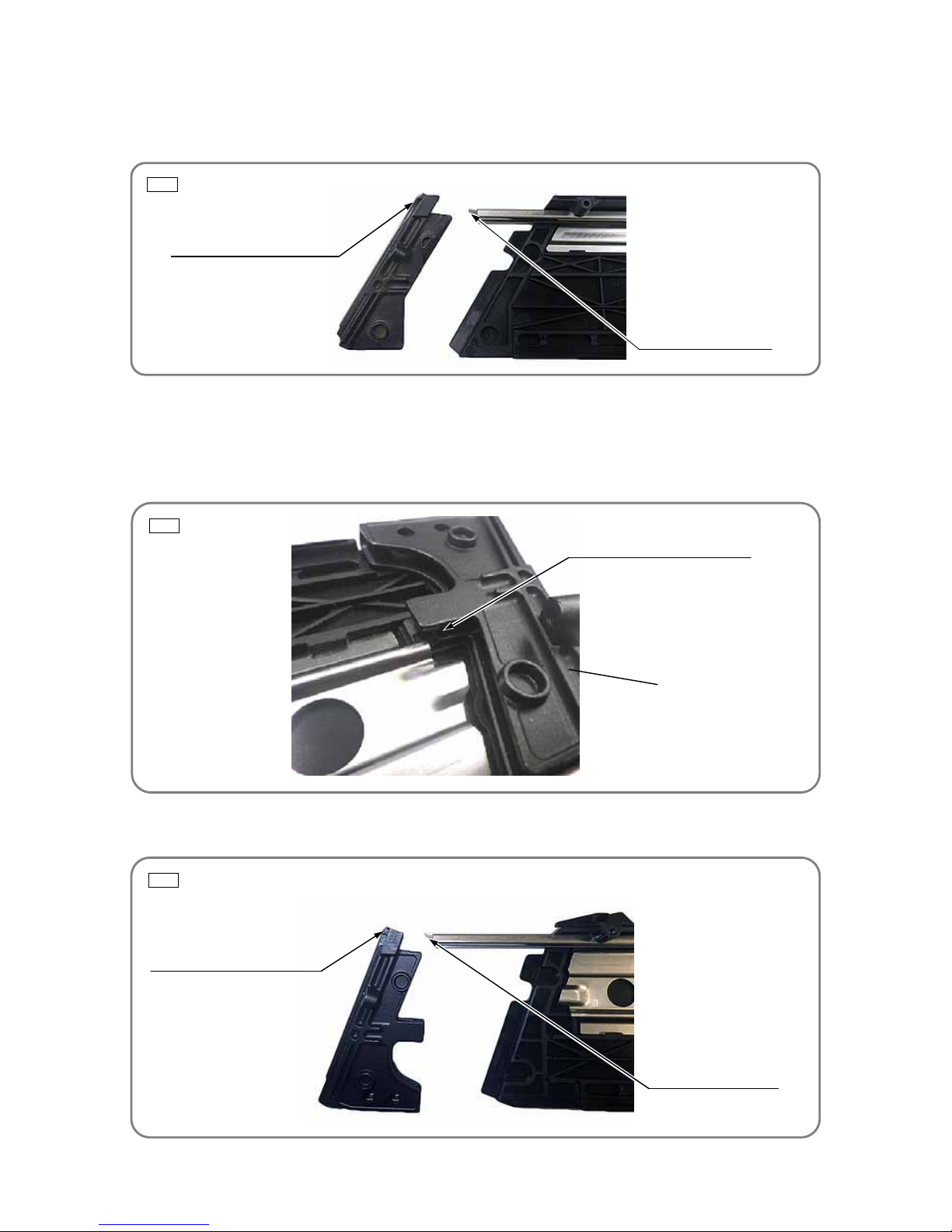
2. Reassembly
(1) Models NR 1890DC and NR 1890DBCL
Reverse the disassembly procedure to reassemble. Note the following points:
• Insert the protrusion of the Nail Rail [87] into the nail head inlet of Blade Guide (B) [76].
(2) Models NR 1890DR and NR 1890DBRL
Reverse the disassembly procedure to reassemble. Note the following points:
• Position the concave portion of Blade Guide (B) (76) on Magazine Cover (B) (84) side between the
Magazine Plate (85) and Magazine Cover (B) (84) as shown below.
• Insert the protrusion of Nail Rail (C) (87) into the nail head inlet of Blade Guide (B) (76).
Nail head inlet of blade guide (B)
Protrusion of the nail rail
Fig. 6
Fig. 8
Concave portion of blade guide (B)
Nail head inlet of blade guide (B)
Protrusion of nail rail (C)
(76)
-12-
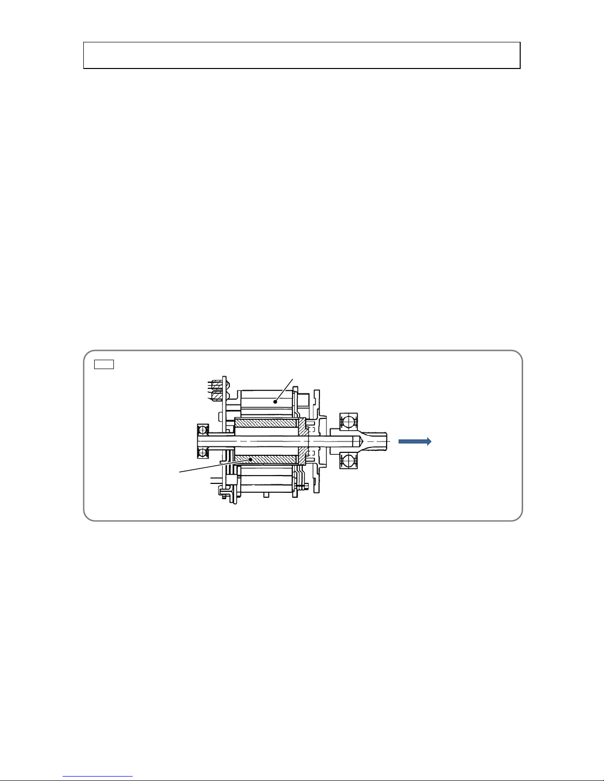
1. Removal of the power assembly and wiring
• The nailer has two Housing Set [46](46) halves: housing (A) with a HITACHI logo mark on one side and
housing (B) on the other side.
• For safety, push the valve core once more and check that compressed air is completely released.
• Remove the Hex. Socket Bolt M6 [1](1) and detach the Top Cover [2](2).
• Remove the fourteen Tapping Screws D4 x 20 [44](44) that fasten housing (A) and housing (B).
• Holding the battery portion of housing (B), gently open and remove the Housing Set [46](46).
• Remove the Trigger [54](54) and Spring (T) [53](53) from housing (A).
• Remove Rubber Cushion (A) [18](18) from housing (A).
• Disconnect the connectors of Sensor (B) [63](63), Sensor (C) [60](60), Switch Cable (A) [52](52), and
Wiring [51](51).
• Remove the two O-rings (I.D 2.5) [50](50) from Switch Cable (A) [52](52). Be careful not to lose the
O-rings.
• Carefully lift the Chamber Base [10](10) and Nose [17](17) to remove the power assembly from housing
(A) and Rotor [83](83).
• Remove the Gear Box [82](82) and Bumper (B) [59](59) from the power assembly.
• Firmly hold the stator of the Wiring [51](51) (as the Rotor [83](83) has strong magnetic force), slowly push
the ball bearing (opposite to the pinion) of the Rotor [83](83) in direction "A" to separate the Wiring
[51](51) from the Rotor [83](83) as shown in the figure below.
• Remove the Wiring [51](51) from housing (A).
• Remove Lever (C) [55](55) from Lever (A) [56](56).
• Remove Lever (A) [56](56) from housing (A).
Disassembly and reassembly of the output section
Fig. 9
A
Rotor
Stator

-13-
2. Disassembly of the power assembly
NOTE: • See pages 23 to 25 for replacement of only the Piston Ass'y [15](15).
• Make alignment marks on the Chamber Base [10](10) and Cylinder [5](5) as shown in the
figure below so as to indicate the coupling positions before disassembling the power
assembly.
Fig. 10
[1](1)
[2](2)
[3](3)
[4](4)
[5](5)
[6](6)
[7](7)
[9](9)
[11](11)
[12](12)
[13](13)
[8](8)
[14](14)
[13](13)
[16](16)
[17](17)
[18](18)
[19](19)
[29](29)
[28](28)
[27](27)
[20](20)
[26](26)
[10](10)
[34](34)
[35](35)
[33](33)
[36](36)
[32](32)
[31](31)
[30](30)
[37](37)
[15](15)
[21](21)
[22](22)
[23](23)
[24](24)
[25](25)
[38](38)
[39](39)
[40](40)
[41](41)
[42](42)
[68](68)
[69](69)
[18](18)
[67](67)
[66](66)
[63](63)
[64](81)
[65](82)
[61](61)
[60](60)
Alignment marks

-14-
Fig. 11
• Remove the valve core from the Chamber Base [10](10) by using a commercial valve core tool. (See Fig.
11.)
• Remove the four Nylock Bolts M6 [11](11) that fasten the Chamber Base [10](10) and Chamber Cover
[4](4), and remove the Chamber Base [10](10).
NOTE: If it is difficult to remove the Chamber Base [10](10), temporarily tighten at least two Nylock
Bolts M6 [11](11) so that the threaded portion is shown 3.5 mm to 6.5 mm as shown in Fig.
12. Mount the reduction valve set and feed compressed air to remove the Chamber Base
[10](10).
• Remove the O-ring (I.D 94.5) [7](7) from the Chamber Base [10](10).
• Push in the Piston Ass'y [15](15) from Blade Guide (A) [70](70) side to the Cylinder [5](5) side to remove
it.
• Remove the Hex. Socket Hd. Bolt M5 [64](64) from the Nose [17](17).
• Move the Chamber Base [10](10) from the Cylinder [5](5) contact surface to the Nose [17](17) side and
secure the Cylinder [5](5) and Chamber Base [10](10) with tape as shown below.
Bit type Tip shape
Fig. 13
[64](64)
Fig. 14
[10](10)
Tape
[17](17)
Fig. 12
Reduction valve set
Temporarily tighten the Nylock Bolts
M6 [11](11) so that the threaded
portion is shown 3.5 to 6.5 mm.
[10](10)

-15-
Fig. 15
• Fix the hexagonal portion of the J-400 special socket. Fit the claws of the J-400 special socket in the
notches on the end surface of the Cylinder [5](5). Loosen the Special Nut M58 [12](12) and turn the Nose
[17](17) to remove it from the Cylinder [5](5).
• Turn the Special Nut M58 [12](12) and remove it from the Cylinder [5](5).
• Remove the Chamber Base [10](10) from the Cylinder [5](5) being careful not to damage the sealing
surfaces.
• Remove the two O-rings (I.D 55.5) [6](6) from the Cylinder [5](5).
• Remove the Slide Ring [13](13) and X-ring [14](14) from the Piston Ass'y [15](15).
• Remove the Piston Bumper [16](16) from the Nose [17](17).
• Remove the Retaining Ring D52 [21](21) from the Nose [17](17) and pull out the Bearing Holder [22](22)
and Pin Wheel [27](27).
NOTE: The Pin Wheel [27](27) can be removed only after removing the Piston Ass'y [15](15).
• Remove the Ball Bearing 6000VV [23](23) and Ball Bearing 6902VV [29](29) from the Pin Wheel
[27](27).
• Remove the Needle Roller D3 [30](30) from the Pin Wheel [27](27) and then remove the Position
Detector [25](25).
• Remove the eight Needle Rollers D4 [32](32) and one Needle Roller D4.5 [26](26) from the Pin Wheel
[27](27). Remove Wheel Spring (A) [31](31), Wheel Spring (B) [28](28), and Pin (A) [33](33).
• Remove Felt (P) [20](20) from the Pin Wheel [27](27).
• Remove the Roll Pin D3 x 20 [71](71) from Blade Guide (A) [70](70)
. Turn the Adjuster [41](41) and
remove Pushing Lever (A) [42](42), Pushing Lever (B) [38](38), and Pushing Lever Spring (B) [36](36).
Fit the claws of the J-400 special socket in the
notches on the Cylinder [5](5) (4 places).
J-400
Repair tool number "J-400"

-16-
Fig. 16
• Remove the Special Bolt M6 [37](37), Adjuster [41](41), Adjuster Spring [40](40), and Steel Ball D3.175
[39](39) from Pushing Lever (B) [38](38).
• Remove the two Nylock Bolts M4 x 14 [35](35) and one Nylock Bolt M4 x 25 [19](19) from the Nose
[17](17), then remove Blade Guide (A) [71](71).
• Remove the Nylock Hex. Socket Hd. Bolt M3 [69](69) and Guide Plate Holder [65](65) from the Nose
[17](17), then remove Guide Plate (P) [68](68).
• Cut the two Wire Bands [61](61) that fixes Sensor (B) [63](63) and Sensor (C) [60](60), then remove
Sensor (C) [60](60).
• Remove the Roll Pin D2.5 [66](66) and Roll Pin D2.5 x 16 [67](67) that fix Sensor (B) [63](63) referring to
page 26.
NOTE: Sensor (C) [60](60) can be removed only after removing Blade Guide (A) [71](71).
3. Reassembly of the power assembly
Reverse the disassembly procedure to reassemble. Note the following points:
• Use the specified tightening torques. (See page 30.)
• Protect the sealing parts (e.g., O-rings, X-rings, valve core, etc.) against contaminants and scratches
during reassembly.
• Always use brand-new seal lock bolts. Never reuse the old bolts.
• Use the alignment marks (made before disassembly) for precise positioning when mounting the Chamber
Base [10](10) on the Cylinder [5](5).
• Slowly tighten the four Nylock Bolts M6 [11](11) to fasten the Chamber Base [10](10) and Chamber Cover
[4](4). Be careful not to pinch and damage the O-ring (I.D 94.5) [7](7).
• Impregnate Felt (P) [20](20) with about 1 g of Molub-Alloy 777-1 grease by hand before reassembly.
• Mount the Pin Wheel [27](27) to the Position Detector [25](25) so that the end surface side of Pin (A)
[33](33) is aligned with the notch of the Position Detector [25](25) as shown in Fig. 16.
NOTE: If the Position Detector [25](25) is not precisely located, an error (causing the orange LED
of the battery indicator to blink) may occur.
• Remove dust from between the Pin Wheel [27](27) and Needle Roller D3 [30](30) and apply about 1.5 g
of Molub-Alloy 777-1 grease to the Needle Roller D3 [30](30), eight Needle Rollers D4 [32](32), and
Needle Roller D4.5 [26](26) evenly.
• Apply about 1.0 g of Isoflex Topas NB52 grease to the X-ring [14](14) and Slide Ring [13](13) of the
Piston Ass'y [15](15) evenly.
Pay special attention to the position of
the Position Detector [25](25).
If the Position Detector [25](25) is
misaligned, the standby position of the
piston is also misaligned. (See page 29.)
[27](27)
[25](25)
Notch
Notch

-17-
Fig. 17
Fig. 18
Fig. 19
• Put the Pin Wheel [27](27) in the Nose [17](17). Facing the notch of the Pin Wheel [27](27) to Blade
Guide (A) [70](70), push the Piston Ass'y [15](15) down to the bottom dead point without meshing with
the eight Needle Rollers D4 [32](32) and Needle Roller D4.5 [26](26) as shown in Fig. 17.
• Mount the Chamber Base [10](10), Special Nut M58 [12](12), and Nose [17](17) to the Cylinder [5](5) in
this order. Apply Three-Bond TB1342H adhesive in the form of a line circling around the cylinder two
times as shown in Fig. 18. Then mount the Special Nut M58 [12](12).
• Mount Sensor (B) [63](63) using a round bar of 2 to 2.5 mm in diameter as shown in Fig. 19 to protect the
root of the wire from being applied force. After mounting Sensor (B) [63](63), remove the round bar.
Round bar
(Remove it after mounting Sensor (B) [63](63).)
Apply TB1342H adhesive here (2 places).
[12](12)
[17](17)
Notch of the Pin Wheel [27](27)
[15](15)
[17](17)
[70](70)
M58 threaded portion

-18-
Fig. 20
Fig. 21
Fig. 21
• Apply Molub-Alloy 777-1 grease to the following area on the Nose [17](17) and then mount Pushing Lever
(B) [38](38).
• Be sure to check Sensor (B) [63](63) according to pages 21 to 22 after reassembling the power assembly.
• Be sure to mount the Hex. Socket Hd. Bolt M5 [64](64) to the Nose [17](17).
• Insert the Rotor [83](83) into the Gear Box [82](82) and check that the Rotor [83](83) turns smoothly by
hand as shown in Fig. 21.
NOTE: If the Rotor [83](83) cannot turn smoothly, the gear may be deformed or damaged. Replace
the Gear Box [82](82) with new one.
• Be sure to mount Bumper (B) [59](59) to the Nose [17](17) as shown in Fig. 22 and then mount the Gear
Box [82](82).
Apply grease here.
[83](83)
[82](82)
[59](59)

-19-
Fig. 22
• If it is difficult to mount the Gear Box [82](82) due to improperly meshed gears, turn the Rotor [83](83) by
hand so that the gears are properly meshed.
• Push the wires in housing (A) of Housing Set [46](46) with a flat-blade screwdriver being careful not to
damage the coating as shown in Fig. 22.
Do not protrude
the wires.
Do not pinch
the wires.
Do not protrude
the wires.
Sensor (C)
Black, blue, red
Sensor (B)
Black, white, red
Black, blue, red
Black, white, red
Ferrite core
Models NR 1890DBCL
and NR 1890DBRL only
Ferrite core
Models NR 1890DBCL
and NR 1890DBRL only

-20-
Fig. 23
Fig. 24
• Check that the wires are not caught and there is no clearance between housings (A) and (B) when putting
housing (A) and housing (B) together.
• After reassembly, check that the terminal of the Wiring [51](51) is properly mounted without mismatch and
it is slightly movable as shown in Fig. 24.
[51](51)

-21-
Fig. 25
4. Checking after reassembly of the power assembly
• Check that Pushing Lever (A) [42](42) moves smoothly without any catch.
• Check that the Adjuster [41](41) rotates smoothly.
• Connect Sensor (B) [63](63) and Sensor (C) [60](60) to the Wiring [51](51) and then connect the terminal
to the battery as shown in Fig. 25 in order to check Sensor (B) [63](63) for normal response.
Operation panel
Power switch
Battery
[51](51)
Operation panel

-22-
Fig. 26
• Insert a pin punch of 5±0.1 mm in diameter between Pushing Lever (B) [38](38) and the wall of the Nose
[17](17) where Sensor (B) [63](63) is inserted. Then push in Pushing Lever (A) [42](42) and keep
pressing the power switch on the operation panel for at least 2 seconds. Check that the LED light on the
operation panel turns on. Next, insert a pin punch of 2.4±0.1 mm in diameter and push in Pushing Lever
(A) [42](42). Keep pressing the power switch on the operation panel for at least 2 seconds. Check that the
LED light on the operation panel remains turned off. (See Fig. 26.)
NOTE: If a pin punch of 5±0.1 mm (0.2±0.0039") in diameter and a pin punch of 2.4±0.1 mm
(0.095±0.0039") in diameter are not available, use the shank of a drill of 5 mm in diameter
and a drill of 2.4 mm in diameter.
• If the LED light remains turned off when inserting a pin punch of 5 mm in diameter during the operation
check of Sensor (B) [63](63) or if the LED light turns on when inserting a pin punch of 2.4 mm in diameter,
Pushing Lever (B) [38](38), Blade Plate (P) [68](38) or Sensor (B) [63](63) may be damaged or deformed.
Check and replace the damaged or deformed part and then perform the operation check of Sensor (B)
[63](63) again.
Pin punch
(5 mm/2.4 mm in diameter)
Push in.

-23-
Fig. 27
NOTE: When replacing only the Piston Ass'y [15](15) with new one, also replace the Needle Roller
D4.5 [26](26) mounted in the Pin Wheel [27](27) with new one included in the brand-new
Piston Ass'y [15](15).
1. Disassembly
• Remove Housing (C) [45](45), magazine ass'y, and Top Cover [2](2) to take out the power assembly and
Wiring [51](51) referring to pages 8 to 12.
Replacement of the piston ass'y
[1](1)
[2](2)
[3](3)
[4](4)
[5](5)
[6](6)
[7](7)
[9](9)
[11](11)
[12](12)
[13](13)
[8](8)
[14](14)
[13](13)
[16](16)
[17](17)
[18](18)
[19](19)
[29](29)
[27](27)
[20](20)
[26](26)
[10](10
)
[34](34)
[35](35)
[33](33)
[36](36)
[32](32)
[31](31)
[30](30)
[37](37)
[21](21)
[23](23)
[24](24)
[25](25)
[38](38)
[39](39)
[40](40)
[41](41)
[42](42)
[68](68)
[69](69)
[18](18)
[66](66)
[64](81)
[65](82)
[60](60)
[61](61)
[63](63)
[22](22)
[28](28)
[15](15)
[67](67)

-24-
Fig. 28
Fig. 29
• Check that compressed air is completely released. Then remove the four Nylock Bolts M6 [11](11) from
the Chamber Base [10](10) and Chamber Cover [4](4) to remove the Chamber Cover [4](4).
NOTE: If it is difficult to remove the Chamber Base [10](10), temporarily tighten at least two Nylock
Bolts M6 [11](11) so that the threaded portion is shown 3.5 mm to 6.5 mm as shown in Fig.
28. Mount the reduction valve set and feed compressed air to remove the Chamber Base
[10](10).
• Push the Piston Ass'y [15](15) from Blade Guide (A) [70](70) side toward the Cylinder [5](5) side to
remove it from the Cylinder [5](5).
• Remove the Retaining Ring D52 [21](21) from the Nose [17](17) and pull out the Bearing Holder [22](22)
and Pin Wheel [27](27).
• Remove the Ball Bearing 6000VV [23](23) from the Pin Wheel [27](27).
• Remove the Needle Roller D3 [30](30) from the Pin Wheel [27](27). Then remove the Position Detector
[25](25).
• Remove the Needle Roller D4.5 [26](26) from the Pin Wheel [27](27). (See Fig. 29.)
2. Reassembly
Reverse the disassembly procedure to reassemble. Note the following points:
• Use the specified tightening torques.
• Insert the Needle Roller D4.5 [26](26) included in the brand-new Piston Ass'y [15](15) into the Pin Wheel
[27](27).
• Mount the Pin Wheel [27](27) to the Position Detector [25](25) so that the end surface side of Pin (A)
[33](33) is aligned with the notch of the Position Detector [25](25) as shown in Fig. 30.
[26](26)
[27](27)
Reduction valve set
Temporarily tighten the Nylock Bolts
M6 [11](11) so that the threaded
portion is shown 3.5 to 6.5 mm.

-25-
Fig. 30
Fig. 31
• Remove dust from between the Pin Wheel [27](27) and Needle Roller D3 [30](30) and apply about 1.5 g
of Molub-Alloy 777-1 grease to the Needle Roller D3 [30](30), eight Needle Rollers D4 [32](32), and
Needle Roller D4.5 [26](26) evenly.
• Apply about 0.2 g of Isoflex Topas NB52 grease to the two Slide Rings [13](13) included in the brand-new
Piston Ass'y [15](15) evenly. Then mount the two Slide Rings [13](13) to the Piston Ass'y [15](15).
• Apply about 1.0 g of Isoflex Topas NB52 grease to the X-ring [14](14) included in the brand-new Piston
Ass'y [15](15) evenly. Then mount the X-ring [14](14) to the Piston Ass'y [15](15).
• Put the Pin Wheel [27](27) in the Nose [17](17). Facing the notch of the Pin Wheel [27](27) to Blade
Guide (A) [70](70), push the Piston Ass'y [15](15) down to the bottom dead point without meshing with
the eight Needle Rollers D4 [32](32) and Needle Roller D4.5 [26](26) as shown in Fig. 31. Apply about
1.5 g of Isoflex Topas NB52 grease to the inside of the Cylinder [5](5) evenly.
NOTE: If the Position Detector [25](25) is not precisely located, an error (causing the orange LED
of the battery indicator to blink) may occur.
• Slowly tighten the four Nylock Bolts M6 [11](11) to fasten the Chamber Base [10](10) and Chamber Cover
[4](4). Be careful not to pinch and damage the O-ring (I.D 94.5) [7](7).
• Perform reassembly of the power assembly according to pages 16 to 20.
Pay special attention to the position of
the Position Detector [25](25).
If the Position Detector [25](25) is
misaligned, the standby position of the
piston is also misaligned. (See page 29.)
[27](27)
[25](25)
Notch
Notch
Notch of the Pin Wheel [27](27)
[15](15)
[17](17)
[70](70)

-26-
Fig. 32
Fig. 33
• Remove Housing (C) [45](45), magazine ass'y, and Top Cover [2](2) to take out the power assembly
referring to pages 8 to 12.
• Remove the Nylock Hex. Socket Hd. Bolt M3 [69](69) and Guide Plate Holder [65](65) from the Nose
[17](17), then remove Guide Plate (P) [68](68).
• Pull out the Roll Pin D2.5 [66](66) and Roll Pin D2.5 x 16 [67](67) protruding from the Nose [17](17) with
nippers as shown in Fig. 32.
• Remove Sensor (B) [63](63) from the Nose [17](17).
• Mount new Sensor (B) [63](63) to the Nose [17](17) and then mount the Roll Pin D2.5 [66](66) as shown
in Fig. 33.
A
Hold the roll pin with the blade edges of nippers.
Pressing against the end surface of the nose, move
the nippers in "A" direction to pull out the roll pin.
Use nippers having no
dent at the blade edges.
Replacement of sensor (B)

-27-
Model name and repair tool
number are indicated on the label.
Fig. 34
Fig. 35
CAUTION: • Be sure to set MAINTENANCE mode (see page 7) and move the Piston Ass'y [15](15)
down to the bottom dead point before feeding or discharging compressed air.
• Be sure to use the specified reduction valve set when feeding compressed air.
• An oil-free compressor should be used to feed compressed air to the nailer.
1. Moving the piston down to the bottom dead point
• Turn on the nailer and switch to MAINTENANCE mode. (See page 7.)
• Repeat the steps below three or four times until the Piston Ass'y [15](15) reaches the bottom dead point.
(1) Move the Feeder Knob [92](92) down to reset the dry-fire lockout mechanism.
(2) Press Pushing Lever (A) [42](42) against a piece of wood.
(3) Pull the Trigger [54](54).
• Check that the driver blade of the Piston Ass'y [15](15) protrudes from the blade guide.
2. Feeding compressed air
• Check that the battery is not mounted in the nailer body.
• Prepare the J-394 reduction valve set (16 GA) specified below.
Model
Model name
indicated on label
Repair tool number Preset feeding pressure
NR1890DC/DBCL
NR1890DR/DBRL
NT 1865DM J-394 (Code No. 371208) 0.5±0.03 MPa (5.1±0.3 kgf/cm
2
)
Blade guide
Pressure regulator
Charge screw
Repair tool number
and feeding pressure
Air plug*
*: Replace the air plug according to your air compressor.
(Air plug: 1/4" NPT pipe thread taper)
O-rings
[54[(54)
[92](92)
Driver blade
Feeding compressed air
[42[(42)
1
2
3

-28-
Fig. 36
Fig. 37
Fig. 38
• Push the valve core and check that no compressed air is left.
• Apply lubricant to the O-ring (S-5) (Code No. 872822) of the charge screw. Always replace a defective
O-ring with a new one.
• Screw in the charge screw into the pressure feeding port of the Chamber Base [10](10).
• Prepare an air compressor (0.7 MPa or higher) and set a delivery pressure of 0.7 to 1.2 MPa.
(See Fig. 37.)
• Connect the reduction valve set to the air compressor for at least 10 seconds to feed compressed air.
(See Fig. 38.)
• Reverse the procedure above for disconnection.
• Quickly mount the Charge Cap [8](8) on the feeding port within 30 seconds after feeding compressed air
to prevent air leaks from the valve section.
Before connecting the reduction valve set
After connecting the reduction valve set
Feeding port

-29-
• Check that no nail is loaded in the magazine.
• Check that Pushing Lever (A) [42](42) moves smoothly without any catch.
• Check that the Adjuster [41](41) rotates smoothly.
• Check that the Trigger [54](54) moves smoothly.
• Check that the Feeder Knob [92](92) slides smoothly.
• Push Pushing Lever (A) [42](42) of the empty nailer (without nails) against a wood material and make
sure the dry-fire lockout mechanism works normally.
• Move Lever (A) [56](56) to the LOCK position and make sure the Trigger [54](54) is completely locked
and cannot be pulled back.
• Turn on the nailer and make sure no LED is blinking to indicate an error state.
• Turn on the nailer and make sure the LEDs on the operation panel light.
• Load the longest nails in the nailer and start nailing. Check that no trouble (e.g., abnormal nailing, unusual
sound, nail head lift) occurs. Press Pushing Lever (A) [42](42) without pulling the Trigger [54](54) in the
contact actuation mode and make sure the nailer does not work.
• After checking the actual nailing, check the position-in-readiness according to the following procedure:
Measure the distance between the tip of Blade Guide (A) [70](70) and the tip of the Piston Ass'y [15](15)
with a caliper and make sure that the distance is 90.2 mm or shorter. If the distance is longer than 90.2
mm, the position detector may be incorrectly mounted. Check whether the position detector is correctly
mounted or not. (See page 16.)
• Do not use the nailer for one day after checking the actual nailing, and then check that the nailer works
normally without any nail heads lifted on the next day by loading the longest nails in the nailer (air leak
check).
Checking after reassembly

-30-
Item No.
Part name
Tightening torque
NR 1890DC
NR 1890DBCL
NR 1890DR
NR 1890DBRL
N•m lbf-ft
[1] (1)
Hex. Socket Bolt M6 9.8 ± 0.8 7.2 ± 0.6
[5] (5)
Cylinder 82 ± 3 60.5± 0.2
[8] (8)
Charge Cap 4.5 ± 0.5 3.3 ± 0.4
[11] (11)
Nylock Bolt M6 12.8 ± 0.8 9.4 ± 0.6
[12] (12)
Special Nut M58 50 ± 1 36.9 ± 0.7
[19][35] (19)(35)
Nylock Bolt (W/Flange) M4 3.4 ± 0.7 2.5 ± 0.5
[34][85] (34)(86)
Nylock Bolt (W/Flange) M5 6.9 ± 0.5 5.1 ± 0.5
[37] (37)
Special Bolt M6 12.7 ± 0.8 9.4 ± 0.6
[44] (44)
Tapping Screw (W/Flange) D4 x 20 (Black) 2.0 ± 0.5 1.5 ± 0.2
[58] (58)
Low Head Hex. Socket Bolt M4 x 8 3.4 ± 0.7 2.5 ± 0.5
[64] (64)
Hex. Socket Hd. Bolt M5 3.0 ± 0.3 2.2 ± 0.2
[69] (69)
Nylock Hex. Socket Hd. Bolt M3 2.45 ± 0.5 1.8 ± 0.4
[89] (89)
Step Bolt M3 1.7 ± 0.17 1.2 ± 0.1
[91] (91)
Tapping Screw (W/Flange) D4 x 16 (Black) 2.8 ± 0.5 2.0 ± 0.4
[93] (93)
Tapping Screw (W/Flange) D5 x 20 (Black) 2.9 ± 0.5 2.2 ± 0.4
Tightening torque

-31-
Fig. 39
Connecting diagram
1. Black
2. Yellow
Trigger switch
Push switch
Pin wheel
switch
Sensor ass'y (B) Sensor ass'y (C)
Battery terminal
Main PCB ass'y
Tact switch PCB ass'y
Sensor PCB
ass'y
M
LD
Black
White
Red
1. Red
2. Blue
3. Black
1. Red
2. White
3. Black
Red
Black
White
*: Alternative part
Ferrite core*
Ferrite core*
(Models NR 1890DBCL and
NR 1890DBRL only)
(Models NR 1890DBCL and
NR 1890DBRL only)

-32-
MODEL
Variable
10 20 30 40 50 60 min.
NR 1890DC
NR 1890DBCL
NR 1890DR
NR 1890DBRL
General Assembly
Blade
Guide (B)
Magazine
Cover (A)
Magazine
Cover (B)
Nail Rail
Magazine
Guard
Magazine
Plate
Pushing
Stopper (A)
Pushing
Stopper (B)
Pushing
Stopper
Spri ng
Feeder
Knob
Nail Feeder
(B)
Ribbon
Spri ng
Nail Feeder
Pin Wheel
Position
Detector
Chamber
Cover
Chamber
Base
Special Nut
M58
O-ring x 2
Cylinder
Piston Blade
Slide Ring
X-Ring
Piston
Bumper
Housing
Trig ger
Rotor
Wiring
Sensor (C)
Gear Box
Adjuster
Pushing
Lever (A)
Pushing
Lever (B)
Magnet
Blade
Guide (A)
Sensor (B)
Nose
Work Flow
Top Cover
Housing (C)
Hook
Pushing
Lever
Spri ng
STANDARD REPAIR TIME (UNIT) SCHEDULES

PNEUMATIC TOOL PARTS LIST
Model NR 1890DC
CORDLESS STRIP NAILER
LIST NO. K858
(E1)
2017 · 7· 12
A
A
1
2
3
4
5
6
12
20
7
8
9
11
10
14
13
15
16
19
17
25
26
27
28
29
504
21
22
23
24
30
32
31
33
34
35
36
37
38
39
40
41
42
67
44
45
43
44
46
53
54
50
52
50
48
47
51
55
56
57
58
83
63
18
84
85
86
87
77
78
79
80
88
70
71
76
75
73
73
72
74
89
90
91 92 93
501
501
61
66
505
502
503
506
64
18
13
60
65
68
69
81
62
59
82
49

PARTS NR 1890DC
DESCRIPTION REMARKS
1 372298 HEX. SOCKET BOLT M6 4
2 372296 TOP COVER 1
3 371012 RUBBER CUSHION (C) 1
4 372337 CHAMBER COVER 1
5 372335 CYLINDER 1
6 372336 O-RING (I.D 55.5) 2
7 372334 O-RING (I.D 94.5) 1
8 371039 CHARGE CAP 1
9 872822 O-RING (S-5) 1
10 372388 CHAMBER BASE 1
11 372338 NYLOCK BOLT M6 4
12 372339 SPECIAL NUT M58 1
13 372320 SLIDE RING 2
14 372319 X-RING 1
15 372318 PISTON ASS'Y 1 INCLUD.13,14,26
16 372317 PISTON BUMPER 1
17 372387 NOSE 1
18 372343 RUBBER CUSHION (A) 2
19 372310 NYLOCK BOLT (W/FLANGE) M4 X 25 1
20 372330 FELT (P) 1
21 372332 RETAINING RING D52 1
22 372331 BEARING HOLDER 1
23 6000VV BALL BEARING 6000VVCMPS2L 1
24 372329 O-RING (I.D 20.22) 1
25 372327 POSITION DETECTOR 1
26 372326 NEEDLE ROLLER D4.5 1
27 372321 PIN WHEEL 1
28 372323 WHEEL SPRING (B) 1
29 6902VV BALL BEARING 6902VV 1
30 372328 NEEDLE ROLLER D3 1
31 372322 WHEEL SPRING (A) 1
32 372325 NEEDLE ROLLER D4 8
33 372324 PIN (A) 1
34 372355 NYLOCK BOLT (W/FLANGE) M5 X 22 2
35 372311 NYLOCK BOLT (W/FLANGE) M4 X 14 2
36 372307 PUSHING LEVER SPRING (B) 1
37 372316 SPECIAL BOLT M6 1
38 372305 PUSHING LEVER (B) 1
39 959148 STEEL BALL D3.175 (10 PCS.) 2
40 372315 ADJUSTER SPRING 2
41 372314 ADJUSTER 1
42 372308 PUSHING LEVER (A) 1
43 NAME PLATE 1
44 301653
TAPPING SCREW (W/FLANGE) D4 X 20 (BLACK) 14
45 372297 HOUSING (C) 1
46 372295 HOUSING SET 1 INCLUD.45
* 47 338890 BATTERY BSL 1860 (USA,CAN) 1 INCLUD.505
* 47 339782 BATTERY BSL 1830C (USA,CAN) 1 INCLUD.505
48 332668 RUBBER CUSHION 1
49 372803 PLATE (A) 1
- 2 - 7 - 17
*ALTERNATIVE PARTS
ITEM
NO.
NO.
USED
CODE NO. CODE NO.

PARTS NR 1890DC
DESCRIPTION REMARKS
50 371020 O-RING (I.D 2.5) 2
51 372291 WIRING 1
52 371019 SWITCH CABLE (A) 1
53 332000 SPRING (T) 1
54 371021 TRIGGER 1
55 331790 LEVER (C) 1
56 326276 LEVER (A) 1
57 372356 HOOK 1
58 331109 LOW HEAD HEX. SOCKET BOLT M4 X 8 3
59 372342 BUMPER (B) 2
60 372302 SENSOR (C) 1
61 6696839 WIRE BAND 2
62 371107 CAUTION LABEL 1
63 372301 SENSOR (B) 1 INCLUD.38
64 372340 HEX. SOCKET HD. BOLT M5 1
65 372313 GUIDE PLATE HOLDER 1
66 372304 ROLL PIN D2.5 1
67 878965 ROLL PIN D2.5 X 16 1
68 372312 BLADE PLATE (P) 1
69 331184 NYLOCK HEX. SOCKET HD. BOLT M3 1
70 372309 BLADE GUIDE (A) 1
71 949685 ROLL PIN D3 X 20 (10 PCS.) 1
72 372349 PUSHING LEVER STOPPER (A) 1
73 372350 SPRING 2
74 372351 PUSHING LEVER STOPPER (B) 1
75 883687 SPRING 1
76 372346 BLADE GUIDE (B) 1
77 885323 NAIL FEEDER (A) 1
78 949506 ROLL PIN D4 X 28 (10 PCS.) 1
79 885324 NAIL FEEDER (B) 1
80 885325 RIBBON SPRING 1
81 372353 CAP NUT M3 1
82 372341 GEAR BOX 1
83 361071 ROTOR 1
84 372345 MAGAZINE COVER (B) 1
85 372354 NYLOCK BOLT (W/FLANGE) M5 1
86 372347 MAGAZINE PLATE 1
87 885341 NAIL RAIL 1
88 372344 MAGAZINE COVER (A) 1
89 372352 STEP BOLT M3 1
90 372348 MAGAZINE GUARD 1
91 307811
TAPPING SCREW (W/FLANGE) D4 X 16 (BLACK) 3
92 886246 FEEDER KNOB 1
93 302089
TAPPING SCREW (W/FLANGE) D5 X 20 (BLACK) 1
7 - 17 - 3 -
*ALTERNATIVE PARTS
NO.
USED
CODE NO.
ITEM
NO.

NR 1890DC
DESCRIPTION REMARKS
* 501 CHARGER (MODEL UC 18YSL3) 1
* 501 CHARGER (MODEL UC 18YFSL) 1
502 943277 HEX. BAR WRENCH 3MM 1
503 944458 HEX. BAR WRENCH 4MM 1
504 875769 PROTECTIVE GLASSES 1
505 329897 BATTERY COVER 1
506 372294 TOOL BAG 1
- 4 - Printed in Japan 7 - 17
(170712N)
*ALTERNATIVE PARTS
STANDARD ACCESSORIES
NO.
USED
CODE NO.
ITEM
NO.

PNEUMATIC TOOL PARTS LIST
Model NR 1890DR
CORDLESS STRIP NAILER
LIST NO. K859
(E1)
2017 · 7· 12
13
69
67
66
64
81
62
48
94
A
1
2
3
4
5
6
12
7
8
9
11
10
14
13
15
16
19
17
25
26
27
28
29
21
22
23
24
30
31
32
33
34
35
36
37
38
39
40
41
42
44
45
43
44
46
53
54
50
52
50
49
47
51
55
56
57
58
83
63
18
84
85
87
77
78
79
80
88
70
71
76
75
73
73
72
74
89
90
91
92
93
A
86
20
18
65
60
61
59
68
504
501
501
505
502
503
506
82

PARTS NR 1890DR
DESCRIPTION REMARKS
1 372298 HEX. SOCKET BOLT M6 4
2 372296 TOP COVER 1
3 371012 RUBBER CUSHION (C) 1
4 372337 CHAMBER COVER 1
5 372335 CYLINDER 1
6 372336 O-RING (I.D 55.5) 2
7 372334 O-RING (I.D 94.5) 1
8 371039 CHARGE CAP 1
9 872822 O-RING (S-5) 1
10 372388 CHAMBER BASE 1
11 372338 NYLOCK BOLT M6 4
12 372339 SPECIAL NUT M58 1
13 372320 SLIDE RING 2
14 372319 X-RING 1
15 371810 PISTON ASS'Y 1 INCLUD.13,14,26
16 372317 PISTON BUMPER 1
17 372387 NOSE 1
18 372343 RUBBER CUSHION (A) 2
19 372310 NYLOCK BOLT (W/FLANGE) M4 X 25 1
20 372330 FELT (P) 1
21 372332 RETAINING RING D52 1
22 372331 BEARING HOLDER 1
23 6000VV BALL BEARING 6000VVCMPS2L 1
24 372329 O-RING (I.D 20.22) 1
25 372327 POSITION DETECTOR 1
26 372326 NEEDLE ROLLER D4.5 1
27 372321 PIN WHEEL 1
28 372323 WHEEL SPRING (B) 1
29 6902VV BALL BEARING 6902VV 1
30 372328 NEEDLE ROLLER D3 1
31 372322 WHEEL SPRING (A) 1
32 372325 NEEDLE ROLLER D4 8
33 372324 PIN (A) 1
34 372355 NYLOCK BOLT (W/FLANGE) M5 X 22 2
35 372311 NYLOCK BOLT (W/FLANGE) M4 X 14 2
36 372307 PUSHING LEVER SPRING (B) 1
37 372316 SPECIAL BOLT M6 1
38 372305 PUSHING LEVER (B) 1
39 959148 STEEL BALL D3.175 (10 PCS.) 2
40 372315 ADJUSTER SPRING 2
41 372314 ADJUSTER 1
42 372308 PUSHING LEVER (A) 1
43 NAME PLATE 1
44 301653
TAPPING SCREW (W/FLANGE) D4 X 20 (BLACK) 14
45 372297 HOUSING (C) 1
46 372295 HOUSING SET 1 INCLUD.45
* 47 338890 BATTERY BSL 1860 (USA,CAN) 1 INCLUD.505
* 47 339782 BATTERY BSL 1830C (USA,CAN) 1 INCLUD.505
48 332668 RUBBER CUSHION 1
49 372803 PLATE (A) 1
- 2 - 7 - 17
*ALTERNATIVE PARTS
ITEM
NO.
NO.
USED
CODE NO. CODE NO.

PARTS NR 1890DR
DESCRIPTION REMARKS
50 371020 O-RING (I.D 2.5) 2
51 372291 WIRING 1
52 371019 SWITCH CABLE (A) 1
53 332000 SPRING (T) 1
54 371021 TRIGGER 1
55 331790 LEVER (C) 1
56 326276 LEVER (A) 1
57 372356 HOOK 1
58 331109 LOW HEAD HEX. SOCKET BOLT M4 X 8 3
59 372342 BUMPER (B) 2
60 372302 SENSOR (C) 1
61 6696839 WIRE BAND 2
62 371107 CAUTION LABEL 1
63 372301 SENSOR (B) 1 INLCUD.38
64 372340 HEX. SOCKET HD. BOLT M5 1
65 372313 GUIDE PLATE HOLDER 1
66 372304 ROLL PIN D2.5 1
67 878965 ROLL PIN D2.5 X 16 1
68 372312 BLADE PLATE (P) 1
69 331184 NYLOCK HEX. SOCKET HD. BOLT M3 1
70 371804 BLADE GUIDE (A) 1
71 949685 ROLL PIN D3 X 20 (10 PCS.) 1
72 371809 PUSHING LEVER STOPPER (A) 1
73 372350 SPRING 2
74 372351 PUSHING LEVER STOPPER (B) 1
75 883687 SPRING 1
76 371805 BLADE GUIDE (B) 1
77 885621 NAIL FEEDER 1
78 949506 ROLL PIN D4 X 28 (10 PCS.) 1
79 885324 NAIL FEEDER (B) 1
80 885325 RIBBON SPRING 1
81 372353 CAP NUT M3 1
82 372341 GEAR BOX 1
83 361071 ROTOR 1
84 371807 MAGAZINE COVER (B) 1
85 371808 MAGAZINE PLATE 1
86 372809 NYLOCK BOLT (W/FLANGE) M5 X 18 1
87 372811 NAIL RAIL (C) 1
88 371806 MAGAZINE COVER (A) 1
89 372352 STEP BOLT M3 1
90 372348 MAGAZINE GUARD 1
91 307811
TAPPING SCREW (W/FLANGE) D4 X 16 (BLACK) 3
92 886246 FEEDER KNOB 1
93 302089
TAPPING SCREW (W/FLANGE) D5 X 20 (BLACK) 1
94 372810 WASHER D14.5 1
7 - 17 - 3 -
*ALTERNATIVE PARTS
NO.
USED
CODE NO.
ITEM
NO.

NR 1890DR
DESCRIPTION REMARKS
* 501 CHARGER (MODEL UC 18YSL3) 1
* 501 CHARGER (MODEL UC 18YFSL) 1
502 943277 HEX. BAR WRENCH 3MM 1
503 944458 HEX. BAR WRENCH 4MM 1
504 875769 PROTECTIVE GLASSES 1
505 329897 BATTERY COVER 1
506 372294 TOOL BAG 1
- 4 - Printed in Japan 7 - 17
(170712N)
*ALTERNATIVE PARTS
STANDARD ACCESSORIES
NO.
USED
CODE NO.
ITEM
NO.
 Loading...