

Page 1

HITACHI PROGRAMMABLE CONTROLLER
APPLICATION MANUAL
NJI-350B (X)
Page 2

WARNING
To ensure that the equipment described by this manual. As well as all equipment connected to and used
with it, operate satisfactorily and safely, all applicable local and national codes that apply to installing and
operating the equipment must be followed. Since codes can vary geographically and can change with
time, it is the user’s responsibility to determine which standard and codes apply, and to comply with
them.
FAILURE TO COMPLY WITH APPLICABLE CODES AND STANDARDS CAN RESULT IN
DAMAGE TO EQUIPMENT AND / OR SERIOUS INJURY TO PERSONNEL.
INSTALL EMERGENCY POWER STOP SWITCH WHICH OPERATES INDEPENDENTLY OF
THE PROGRAMMABLE CONTROLLER TO PROTECT THE EQUIPMENT AND / OR
PERSONNEL IN CASE OF THE CONTROLLER MALFUNCTION.
Personnel who are to install and operate the equipment should carefully study this manual and any
others referred to by it prior to installation and / or operation of the equipment. Hitachi, Ltd. constantly
strives to improve its products, and the equipment and the manual(s) that describe it may be different
from those already in your possession.
If you have any questions regarding the installation and operation of the equipment, or if more
information is desired, contact your local Authorized Distributor or Hitachi, Ltd.
IMPORTANT
THIS EQUIPMENT GENERATES, USES, AND CAN RADIATE RADIO FREQUENCY ENERGY AND, IF
NOT INSTALLED AND USED IN ACCORDANCE WITH THE INSTRUCTION MANUAL, MAY CAUSE
INTERFERENCE TO RADIO COMMUNICATIONS. AS TEMPORARILY PERMITTED BY REGULATION,
IT HAS NOT BEEN TESTED FOR COMPLIANCE WITH THE LIMITS FOR CLASS A COMPUTING
DEVICES PURSUANT TO SUBPART J OF PART 15 OF FCC RULES, WHICH ARE DESIGNED TO
PROVIDE REASONABLE PROTECTION AGAINST SUCH INTERFERENCE.
OPERATION OF THIS EQUIPMENT IN A RESIDENTIAL AREA IS LIKELY TO CAUSE INTERFERENCE
IN WHICH CASE THE USER, AT HIS OWN EXPENSE, WILL BE REQUIRED TO TAKE WHATEVER
MEASURES MAY BE REQUIRED TO CORRECT THE INTERFERENCE.
Page 3

LIMITED WARRANTY AND IMITATION OF LIABILITY
Hitachi, Ltd. (Hitachi) warrants to the original purchaser that the programmable controller (PLC)
manufactured by Hitachi is free from defects in material and workmanship under normal use and
service. The obligation of Hitachi under this warranty shall be limited to the repair or exchange of any
part or parts which may prove defective under normal use and service within eighteen (18) months from
the date of manufacture or twelve (12) months from the date of installation by the original purchaser
which ever occurs first, such defect to be disclosed to the satisfaction of Hitachi after examination by
Hitachi of the allegedly defective part or parts. This warranty in expressly in lieu of all other warranties
expressed or implied including the warranties of merchantability and fitness for use and of all other
obligations or liabilities and Hitachi neither assumes, nor authorizes any other person to assume for
Hitachi, any other liability in connection with the sale of this PLC. This warranty shall not apply to this
PLC or any part hereof which has been subject to accident, negligence, alteration, abuse, or misuse.
Hitachi makes no warranty whatsoever in respect to accessories or parts not supplied by Hitachi. The
term "original purchaser", as used in this warranty, shall be deemed to mean that person for whom the
PLC in originally installed.
In no event, whether as a result of breach of contract, warranty, tort (including negligence) or otherwise,
shall Hitachi or its suppliers be liable for any special, consequential, incidental or penal damages
Including, but not limited to, loss of profit or revenues, loss of use of the products or any associated
equipment, damage to associated equipment, cost of capital, cost of substitute products, facilities,
services or replacement power, down time costs, or claims of original purchaser’s customers for such
damages.
To obtain warranty service, return the product to your distributor, or send it with a description of the
problem, proof of purchase, post paid, insured, and in a suitable package to:
Quality Assurance Dep.
Hitachi Industrial Equipment Systems Co., Ltd.
46-1, Ooaza-Tomioka Nakajo-machi
Kitakanbara-gun, Niigata-ken
959-2608 JAPAN
Page 4

Copyright 2000 by Hitachi Industrial Equipment Systems Co., Ltd.
All Rights reserved - Printed in Japan
The information and/or drawings set forth in this document and all rights in and to inventions disclosed herein and
patents which might be granted thereon disclosing or employing and the materials, techniques or apparatus described
herein are the exclusive property of Hitachi, Ltd.
No copies of the information or drawings shall be made without the prior consent of Hitachi, Ltd.
Hitachi, Ltd. provides customer assistance in varied technical areas. Since Hitachi does not posses full access to data
concerning all of the uses and applications of customer‘s products, responsibility is assumed by Hitachi neither for
customer product design nor for any infringements of patents or rights of others which may result from Hitachi
assistance.
The specifications and descriptions contained in this manual were accurate at the time they were approved for printing.
Since Hitachi, Ltd. Incorporated constantly strives to improve all its products, we reserve the right to make changes to
equipment and/or manuals at any time without notice and without incurring any obligation other than as noted in this
manual.
Hitachi, Ltd. assumes no responsibility for errors that may appear in this manual.
As the product works with user program and Hitachi, Ltd. cannot test all combination of user program components, it is
assumed that a bug or bugs may happen unintentionally. If it is happened: please inform the fact to Hitachi, Ltd. or its
representative. Hitachi will try to find the reason as much as possible and inform the countermeasure when obtained.
Nevertheless Hitachi, Ltd. intends to make products with enough reliability, the product has possibility to be damaged at
any time. Therefore personnel who are to install and operate the equipment has to prepare with the counter-measure such
as power off switch can be operated independently of the controller. Otherwise, it can result in damage to equipment
and/or serious injury to personnel.
Page 5
Safety Precautions
Read this manual and attached documents thoroughly before installing and operating this unit, and performing
maintenance or inspection of this unit in order to use the unit correctly. Be sure to use this unit after acquiring adequate
knowledge of the unit, all safety information, and all precautionary information. Also, be sure to deliver this manual to
the person in charge of maintenance.
Safety caution items are classified as “Danger” and “Caution” in this document.
DANGER
CAUTION
However, depending on the situation, items marked with may result in major accidents.
Both of these items contain important safety information, so be sure to follow them closely.
Icons for prohibited items and required items are shown below:
: Indicates a prohibited item (item that cannot be performed). For example, when open flames are prohibited,
is shown.
: Indicates a required item (item that must be performed). For example, when grounding must be performed,
is shown.
: Cases in which, if handled incorrectly, a dangerous situation may occur, resulting in
possible death or severe injury.
: Cases in which, if handled incorrectly, a dangerous situation may occur, resulting in
possible minor to medium injury to the body, or only mechanical failure.
CAUTION
1. Installation
CAUTION
• Use this product in an environment as described in the catalogue and this document.
If this product is used in an environment subject to high temperature, high humidity, excessive dust, corrosive
gases, vibration or shock, it may result in an electric shock, fire or malfunction.
• Installation this product according to the instructions in this manual.
If installation is not performed correctly, it may result in falling, malfunction, or an operational error of the unit.
• Never allow foreign objects such as wire chips to enter the unit.
They may cause a fire, malfunction, or failure.
Page 6
2. Wiring
REQUIRED
• Always perform grounding (FE terminal).
If grounding is not performed, there is a risk of an electric shock or malfunction.
CAUTION
• Connect a power supply that meets the rating.
If a power supply that does not meet the rating is connected, it may result in a fire.
• Any wiring operation should only be performed by a qualified technician.
If wiring is performed incorrectly, it may result in a fire, failure, or electric shock.
3. Precautions When Using the Unit
DANGER
• Never touch the terminals while the power is on.
There is a risk of an electric shock.
• Configure the emergency stop circuit, interlock circuit and other related circuits external to the programmable
controller (referred to as the PLC in this document).
Otherwise, a failure in the PLC may damage the equipment or result in a serious accident.
Never interlock the unit with the external load via the relay drive power supply of the relay output module.
CAUTION
• Before performing program change, forced output, run, stop and other operations while the unit is in operation, be
sure to check the validity of the applicable operation and safety.
An operation error may damage the equipment or result in a serious accident.
• Be sure to power on the unit according to the designated power-on sequence.
Otherwise, an erroneous operation may damage the equipment or result in a serious accident.
Page 7
4. Maintenance
DANGER
• Never connect the
short circuit the battery.
There is a risk of an explosion or fire.
and of the battery in reverse. Also, never charge, disassemble, heat, place in fire, or
PROHIBITED
• Never disassemble or modify the unit.
These actions may result in a fire, malfunction, or failure.
CAUTION
• Be sure to turn off the power supply before removing or attaching the module/unit.
Otherwise, it may result in an electric shock, malfunction, or failure.
Page 8

Revision History
No. Description of Revision Date of Revision Manual Number
1 Appendix-1 Instruction Support
FUN92 to 96 of H-4010
{ -> ×.
2000/11 NJI-350 (X)
Appendix-2 Task code H28
Corrected explanation of Timer counter number.
2 Postscript of battery error detection. (3.2 chapters item
2000/12 NJI-350A (X)
number 26, 15 chapters (4) )
Correct a description of digital filter . (8.7 chapters)
Addition of appendix 3.
3 28 points expansion units added.
2003/10 NJI-350B (X)
Analog expansion module added.
Circuit diagram added in chapter 3
FUN 5, TRNS/RECV command added in chapter 5.
Page 9

Table of Contents
Chapter 1 Features ..................................................................................................................................... 1-1 to 1-2
Chapter 2 System Overview....................................................................................................................... 2-1 to 2-2
Chapter 3 Function and Performance Specifications ...............................................................................3-1 to 3-14
3.1 General Specifications ............................................................................................................. 3-1
3.2 Function Specifications............................................................................................................ 3-2
3.3 Performance Specifications...................................................................................................... 3-6
3.3.1 Calculation Specifications ............................................................................................ 3-6
3.3.2 Input Specifications ...................................................................................................... 3-7
3.3.3 Output Specifications.................................................................................................... 3-8
3.3.4 High-Speed Counter Specifications............................................................................ 3-12
3.3.5 PWM Output/Pulse Train Output Specifications........................................................ 3-12
3.3.6 Analogue Input Specifications.................................................................................... 3-12
3.3.7 Analogue Output Specifications ................................................................................. 3-13
3.3.8 Potentiometer Analogue Input Specifications............................................................. 3-14
3.3.9 Interrupt Input Specifications ..................................................................................... 3-14
3.3.10 Backup ........................................................................................................................ 3-14
3.3.11 Expansion ................................................................................................................... 3-14
3.3.12 Clock Function............................................................................................................3-15
3.3.13 Power Supply for Sensor ............................................................................................ 3-16
Chapter 4 Product lineup and wiring .......................................................................................................4-1 to 4-18
4.1 Product lineup.......................................................................................................................... 4-1
4.2 10-Point Basic Unit.................................................................................................................. 4-3
4.3 14-Point Basic Unit.................................................................................................................. 4-4
4.4 23-Point and 28-Point Basic Unit ............................................................................................ 4-5
4.5 Expansion Unit......................................................................................................................... 4-6
4.6 Terminal Layout and Wiring.................................................................................................... 4-7
4.7 Weights and Power Consumption .......................................................................................... 4-16
4.8 Exterior Dimensions .............................................................................................................. 4-17
Chapter 5 Instruction Specifications...................................................................................................... 5-1 to 5-146
5.1 Instruction Classifications ........................................................................................................ 5-1
5.2 List of Instructions................................................................................................................... 5-2
5.3 Instruction Specification Details............................................................................................5-13
Chapter 6 I/O Specifications...................................................................................................................... 6-1 to 6-6
6.1 I/O Assignment ........................................................................................................................ 6-2
6.2 External I/O Numbers.............................................................................................................. 6-3
6.3 Internal Output Numbers.......................................................................................................... 6-6
Page 10

Chapter 7 Programming............................................................................................................................. 7-1 to 7-8
7.1 Memory Size and Memory Assignment ................................................................................... 7-1
7.2 Programming Devices .............................................................................................................. 7-2
7.3 Programming Methods............................................................................................................. 7-3
7.4 Program Transfer ..................................................................................................................... 7-7
Chapter 8 High speed counter, PWM/Pulse train output and Analogue I/O............................................ 8-1 to 8-22
8.1 Input/Output Function.............................................................................................................. 8-1
8.1.1 Initial Setting for Input/Output Function ...................................................................... 8-1
8.1.2 Operation Mode............................................................................................................ 8-2
8.1.3 Input/Output Setting .................................................................................................... 8-3
8.1.4 Input/Output Setting (Mode 10) ................................................................................... 8-4
8.1.5 Special Output Operation in CPU STOP Status ........................................................... 8-5
8.1.6 Pulse / PWM Output adjustment................................................................................... 8-5
8.2 High-Speed Counter (Single-Phase) ........................................................................................ 8-6
8.2.1 Operation of Single-Phase Counter............................................................................... 8-6
8.2.2 Setting of Single-Phase Counter ................................................................................... 8-8
8.3 High-Speed Counter (Two-Phase Counter)............................................................................ 8-10
8.3.1 Operation of the Two-Phase Counters........................................................................ 8-10
8.3.2 Setting of Two-Phase Counter.................................................................................... 8-13
8.4 PWM Output.......................................................................................................................... 8-15
8.4.1 Operation of PWM Output ......................................................................................... 8-15
8.4.2 Setting of PWM Output .............................................................................................. 8-16
8.5 Pulse Train Output ................................................................................................................. 8-18
8.5.1 Operation of Pulse Output .......................................................................................... 8-18
8.5.2 Setting of Pulse Output ............................................................................................... 8-19
8.6 Interrupt Input........................................................................................................................ 8-21
8.7 Digital Filter........................................................................................................................... 8-21
8.8 Potentiometers........................................................................................................................ 8-22
8.9 Analogue Input....................................................................................................................... 8-23
8.10 Analogue Output.................................................................................................................... 8-23
8.11 Analogue Expansion unit ....................................................................................................... 8-24
Chapter 9 PLC Operation ........................................................................................................................9-1 to 9-12
9.1 RUN Start ................................................................................................................................ 9-2
9.1.1 Normal Scan ................................................................................................................. 9-3
9.1.2 Periodical Scan ............................................................................................................. 9-5
9.1.3 Interrupt scan ................................................................................................................ 9-6
9.1.4 Relationship of Each Scan Type ................................................................................... 9-8
9.2 Online Change in RUN ............................................................................................................ 9-9
9.3 Instantaneous Power Failure ..................................................................................................9-10
9.4 Operation Parameter .............................................................................................................. 9-11
9.5 Test Operation........................................................................................................................ 9-12
9.6 Forced Set/Reset .................................................................................................................... 9-12
9.7 Forced Output ........................................................................................................................ 9-12
Page 11

Chapter 10 PLC Installation, Mounting, Wiring......................................................................................10-1 to 10-8
10.1 Installation ............................................................................................................................. 10-1
10.2 Wiring .................................................................................................................................... 10-3
Chapter 11 Communication Specifications............................................................................................11-1 to 11-10
11.1 Port function .......................................................................................................................... 11-1
11.2 Port 1...................................................................................................................................... 11-1
11.3 Port 2...................................................................................................................................... 11-3
11.4 General purpose port (Port 1,2) ............................................................................................. 11-4
11.5 Modem Control Function....................................................................................................... 11-5
11.5.1 Configuration.............................................................................................................. 11-5
11.5.2 AT Commands............................................................................................................ 11-5
11.6 Connecting to the Ports .......................................................................................................... 11-8
11.6.1 Port 1 .......................................................................................................................... 11-8
11.6.2 Port 2 .......................................................................................................................... 11-9
Chapter 12 Error Code List and Special Internal Outputs .....................................................................12-1 to 12-14
12.1 Error Codes ............................................................................................................................ 12-1
12.2 Syntax and Assembler Error Codes........................................................................................ 12-3
12.3 Operation Error Codes ........................................................................................................... 12-4
12.4 Bit Special Internal Output Area............................................................................................ 12-5
12.5 Word Special Internal Output Area........................................................................................ 12-9
Chapter 13 Troubleshooting ..................................................................................................................13-1 to 13-16
13.1 Error Display and Actions...................................................................................................... 13-1
13.2 Checklist when Abnormality Occurred .................................................................................. 13-5
13.3 Procedures to Solve Abnormality .......................................................................................... 13-6
Chapter 14 Operation Examples............................................................................................................ 14-1 to 14-16
Chapter 15 Daily and Periodic Inspections.............................................................................................. 15-1 to 15-2
Appendix 1 H-Series Instruction Support Comparison Chart.................................................................................A-1
Appendix 2 Standards...........................................................................................................................................A-11
Page 12

MEMO
Page 13

Chapter 1 Features
1. Multifunctional all-in-one type PLC
The MICRO-EH is a multifunctional all-in-one type PLC that contains all necessary parts—a power supply and
CPU parts as well as I/O units--within one unit.
Three sizes of PLCs are available: 10, 14, and 28 points. A type with 23 points plus three points of analog I/O
having the same size as the 28-point PLC is also available. Moreover, for PLCs with more than 14 points, it is
possible to install additional 14 or 28 point expansion units up to four units. Thus, the MICRO-EH can control a
wide range of systems from small to medium size.
2. Simplified positioning by counter inputs and pulse train outputs
The function of inputs/outputs can be selected from four modes. By selecting a mode, inputs/outputs that are used as
normal inputs/outputs can be set as counter inputs and pulse train outputs. Through a combination of these special
inputs/outputs, it is possible to control positioning without using special modules.
3. Simplified instrument system by analog integration
For the 23-point PLC, there are two points of analog input and one point of analog output for which both current
and voltage can be selected. High performance analog channels, with a resolution of 12 bits and an overall accuracy
of ±1 % or less, can be used without requiring special settings of the channels; thus, a simplified instrument system
can easily be implemented.
4. Superior upward compatibility
The MICRO-EH has been developed as a part of the EH/H series family.
Debugging and programming can be performed using the same concept as for the EH/H series.
In addition, the MICRO-EH software property can effectively be applied to the EH/H series for future system
expansion.
Chapter 1 Features
5. Easy maintenance through removable terminal blocks and installation on a DIN rail
All models of the MICRO-EH series support the DIN rail so that the PLC can easily be mounted and dismounted. In
addition, the I/O section of the 14-point PLC or more utilizes a removable terminal block. Thus, erroneous and
faulty wiring that may occur when connecting to external devices can be reduced.
6. Remote maintenance through modem connection
Communication with remote sites can be performed via dial-up line by connecting a modem to port 1 on the 14point PLC or more of the MICRO-EH series. It is possible to monitor and manage remote systems from an office or
monitor room.
7. Easily adjustable potentiometer
The 14-point PLC or more of the MICRO-EH series supports two potentiometers.
By using these potentiometers, it is possible to rewrite internal output values in real-time by one driver without using
peripheral devices. Since the resolution of the potentiometer is 10 bits, it is possible to set any value from 0 to 3FFH.
To obtain stable analog values of the potentiometers, it is possible to sample 1 to 40 analog values of the
potentiometers and average them.
8. Maintaining programs without a battery
It is possible to retain user programs in case of out-of battery or no battery, since FLASH memory is used as the
backup memory for the user programs. However, a battery is necessary for data memory backup. (See the Notes in
Chapter 7.1 for a list of precautionary details.)
9. Support for various programming languages
The MICRO-EH supports “Pro-H,” the programming software that allows creating programs in five programming
languages regulated in IEC1131-3. This means that customers who have learned languages other than Ladder can
easily create programs with this programming software.
10. Compliant with overseas specifications as standard
All types of MICRO-EH PLCs have obtained the CE mark, C-TICK and UL. Therefore, systems in which these
PLCs are installed can be exported without requiring any modification.
1-1
Page 14

MEMO
Chapter 1 Features
1-2
Page 15
Chapter 2 System Overview
This chapter describes the system configuration of the MICRO-EH.
The MICRO-EH is an all-in-one type programmable controller, and has the following system configuration.
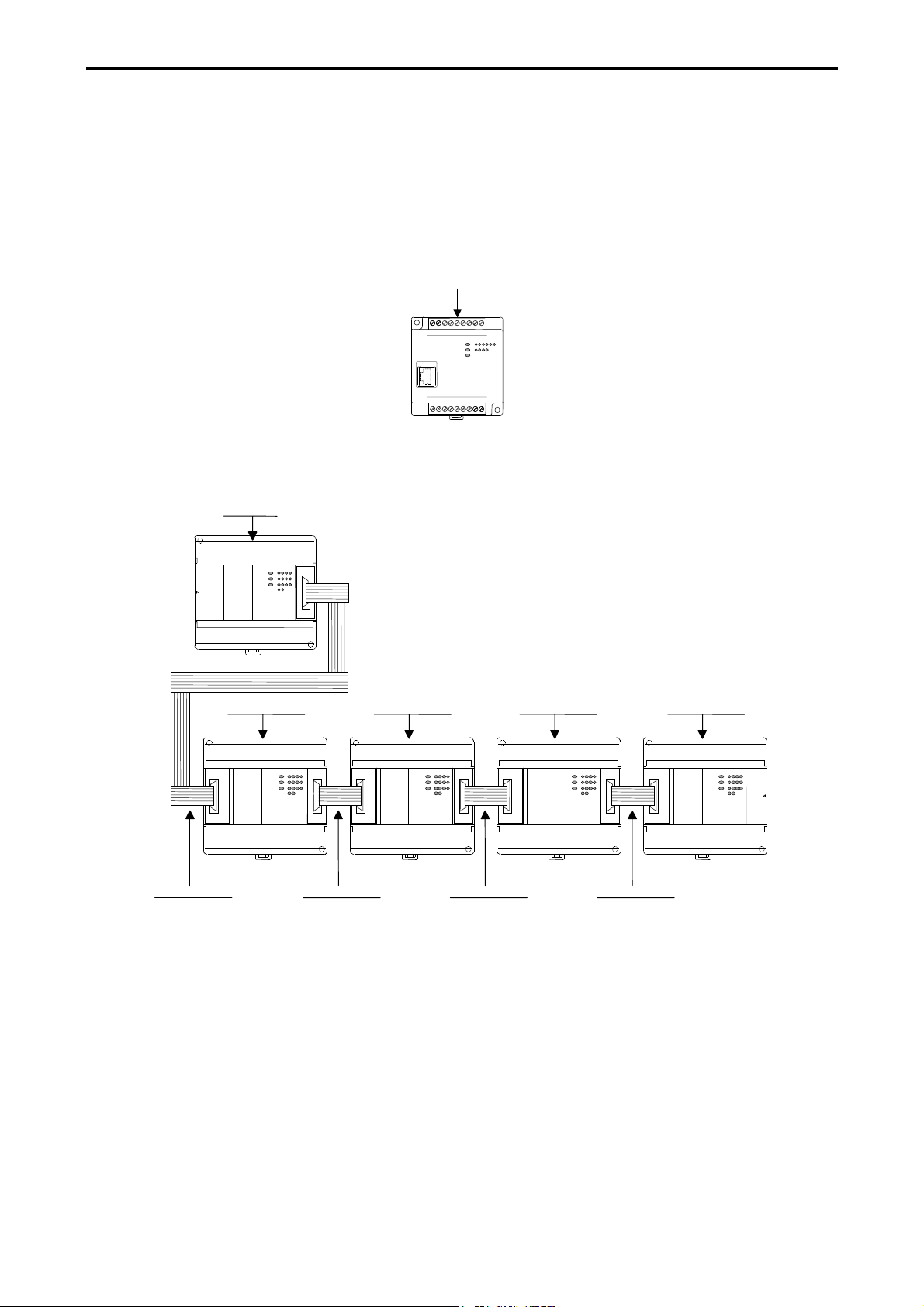
1] Basic unit
Figure 2.1 10-point type system configuration diagram
Chapter 2 System Overview
1] Basic unit
2] Expansion unit2] Expansion unit2] Expansion unit2] Expansion unit
3] Expansion cable3] Expansion cable3] Expansion cable3] Expansion cable
Figure 2.2 14-point type system configuration diagram
2-1
Page 16
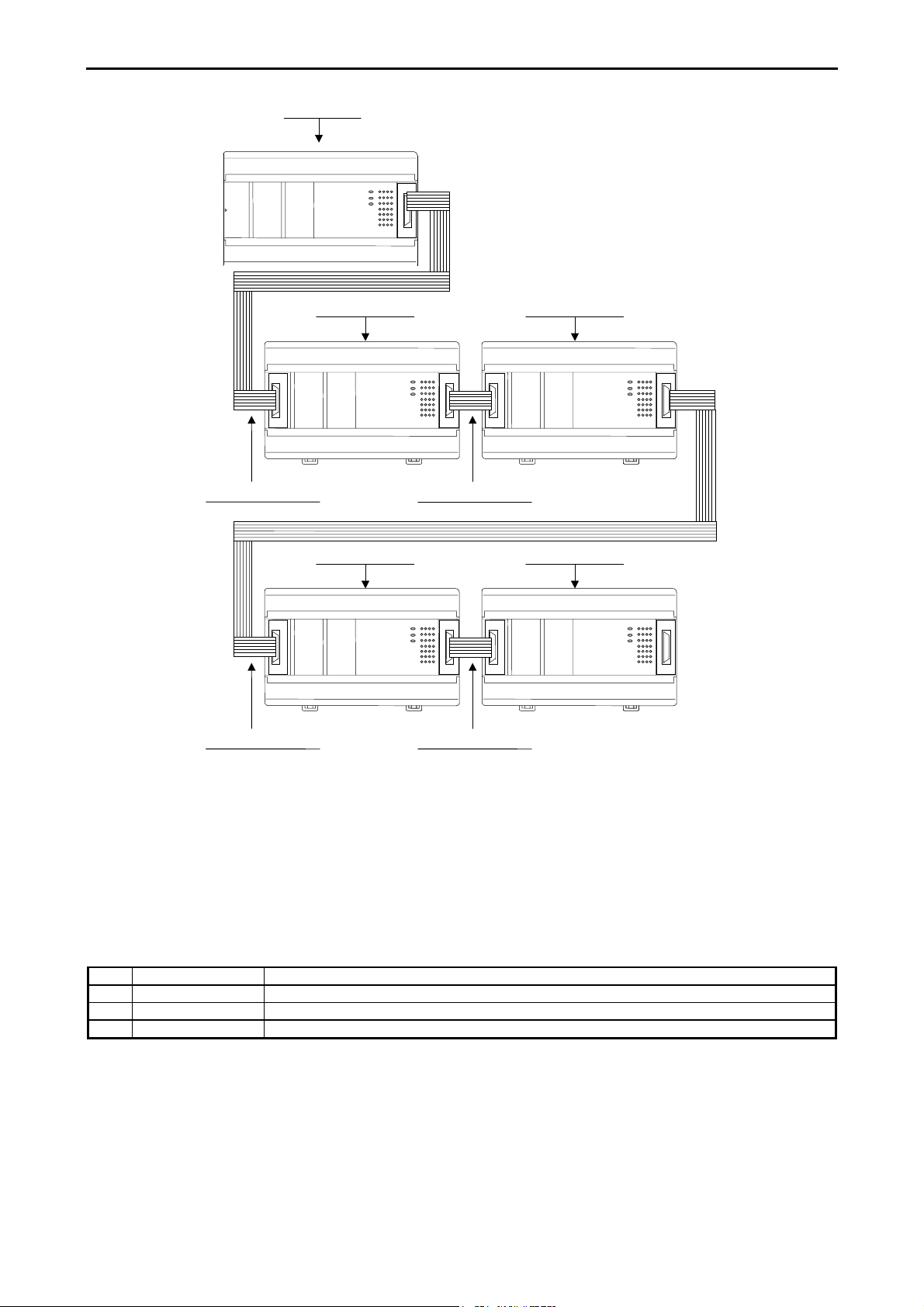
[1] Basic unit
Chapter 2 System Overview
[2] Expansion unit
[3] Expansion cable
[2] Expansion unit [2] Expansion unit
[3] Expansion cable [3] Expansion cable
[3] Expansion cable
[2] Expansion unit
Figure 2.3 23,28-point type system configuration diagram
No restriction for combination of 14,23,28 points, and basic/expansion unit.
14 points basic unit can handle any type of expansion units, and 23/28 points basic unit as well.
No. Device name Description
1] Basic unit Calculates, imports inputs, and controls outputs according to the contents of user programs.
2] Expansion unit 14 points digital unit, 4 in/2 out analog unit
3] Expansion cable Cable for connecting the basic unit and expansion unit, or between expansion units.
2-2
Page 17

Chapter 3 Function and Performance Specifications
Chapter 3 Function and Performance
Specifications
3.1 General Specifications
Item Specification
Power supply type AC DC
Power voltage 100/110/120 V AC (50/60 Hz),
200/220/240 V AC (50/60 Hz)
Power voltage fluctuation
range
Current consumption Please refer to 4.7, “Weights and Power Consumption.”
Allowable momentary power
failure
Operating ambient temp.
Storage ambient temp.
Operating ambient humidity 5 to 95 % RH (no condensation)
Storage ambient humidity 5 to 95 % RH (no condensation)
Vibration proof Conforms to JIS C 0911
Noise resistance
Supported standards Conforms with UL, CE markings and C-TICK
Insulation resistance
Dielectric withstand voltage 1,500 V AC for one minute between the AC external terminal and the protection earth (PE)
Grounding Class D dedicated grounding (grounded by a power supply module)
Environment used No corrosive gases and no excessive dirt
Structure Attached on an open wall
Cooling Natural air cooling
85 to 100 V AC: For a momentary power
100 to 264 V AC: For a momentary power
{ Noise voltage 1,500 Vpp Noise pulse width 100 ns, 1 µs
{ Based on NEMA ICS 3-304
{ Static noise: 3,000 V at metal exposed area
{ Conforms with EN50081-2 and EN50082-2
20 MΩ or more between the AC external terminal and the protection earth (PE) terminal (based
85 to 264 V AC wide range 19.2 to 30 V DC
19.2 to 30 V DC: For a momentary power
failure of less than 10 ms,
operation continues
failure of less than 20 ms,
operation continues
0 to 55 °C
-10 to 75 °C
(Noise created by the noise simulator is applied across the power supply module's input
terminals. This is determined by our measuring method.)
on 500 V DC mega)
terminal
24 V DC
failure of less than 10 ms,
operation continues
3-1
Page 18

Chapter 3 Function and Performance Specifications
3.2 Function Specifications
The functions available in the MICRO-EH are described in the table below.
No. Item Description
1 Basic functions The following functions can be executed when constructing a system using the PLC.
1] An input signal is received from the control object, operations are performed according to
the contents of the program created by the user and the results are output as an output signal.
Also, operation results and progress information can be retained in the internal output area.
2] Power is supplied to the main module, system starts to run, and the operation described
above is performed continuously until the power is shut down or the system stops running.
3] The information retained internally can be extracted by a device connected externally or can
be set in other information. Also, this information is initialized at the time the system starts
running, but it can also be retained depending on the user settings.
4] Operating status can be confirmed with the LED display of each unit or with an external
device that has been connected.
2 Setting and display The following have been provided for the user to set or confirm various types of operation
status:
1] DIP switch (basic unit)
This specifies the CPU communication function setting and operation mode, etc. (except for
10-point type)
2] RUN switch (basic unit)
It can instruct to run and stop. (external input for 10-point type)
3] LED display (basic unit and expansion unit)
Indicates the power system status, operating status and I/O operation status.
4] Communication connector (basic unit)
This can connect external devices using RS-232C, RS-485, RS-422. (only the 23-point and
28-point types with RS-485, RS-422)
5] Expansion connector (basic unit and expansion unit)
This allows installation of additional input/output. (except for 10-point type)
6] Terminal block (basic unit and expansion unit)
This performs the connections for supplying power, and for handling signals with the
control object.
3 Number of I/O points The number of points that can be controlled with respect to the control object is as follows:
1] External inputs/outputs
The number of points that can be use for external inputs/outputs differs depending on the
basic unit. The 10-point type cannot expand the inputs/outputs. For the 14-point, 23-point
and 28-point types, a maximum of 4 expansion units can be connected. The I/O numbers for
inputs are indicated by X, WX, DX and outputs are indicated by Y, WY, DY.
2] Internal outputs
These are areas for temporarily storing information. The I/O numbers include M, WM, DM,
R, WR, DR.
3] A timer counter is provided internally.
4] Array (corresponding to a substitution statement only)
An array of I/O numbers can be expressed by enclosing by parentheses.
4 User program
memory
The program in which the control contents have been described can be stored. This FLASH
memory resides in the basic unit.
1] The contents of this memory will be maintained even if the power is shut off. Because of
this, it is necessary to initialize the memory since it may have undefined after the unit is
purchased.
2] Programming is done using peripheral units such as programming software (LADDER
EDITOR) for the H-series programmable controllers.
3] The instructions that can be used are those designated by the H-series ladder. See the list of
instructions for details.
4] A battery is not required to retain the contents of the user program. Always save the created
programs to a floppy disk just in case an unexpected problem occurs.
3-2
Page 19

Chapter 3 Function and Performance Specifications
No. Item Description
5 Control method With the PLC, the user programs are converted in batch at operation startup, and the programs
after conversion will be executed in order as they are read one by one.
1] The method used for data I/O is that after the I/O data (information) is scanned (execution
from the head of the program to the end), it is updated in group. If refresh of external I/O is
required during scanning (refresh method), use the refresh instruction.
2] Apart from the program that will be normally executed, a periodic scan program which
interrupts the normal program at a fixed time intervals and is executed, can be created. The
time intervals are 10 ms, 20 ms and 40 ms.
3] The user programs are executed from the head of the program to the end, and are once again
repeated after performing the system processing that updates the lapsed timer value,
refreshes I/O, and performs communication with peripheral units.
6 Run/stop control Running and stopping the PLC is normally performed by the user.
1] Turn on the RUN switch to start operation for the 14-point type or higher. Turn this switch
off to stop operation.
For the 10-point type, turn on the RUN input terminal to start operation. Turn it off to stop
operation.
2] The start and stop operations can be performed with designated external inputs or internal
outputs by designating the operation control inputs with a programming unit.
3] Apart from the operation described above, if a malfunction is detected in the system while it
is running, operation stops and the outputs are aborted (OFF).
4] If the power is shut off and then turned back on while the system is running, operation starts.
When the power shuts off, turn off the power to the PLC, then shut off the external input
power. When turning the power back on, turn on the external input power before turning on
the power to the PLC.
5] When starting operation, do so after clearing internal information which is not designated
for storage during power failure. When stopping operation, leave the internal information as
is, turn off the outputs and then stop the operation.
6] When the power has been cut off for longer than the time allowed for the momentary power
failure, then depending on the system load status, either operation continues or the system
perceives that a power shut off has occurred and restarts operation. To resume operation
securely, have the power remain off for 1 minute or longer.
7 Operation parameters Each type of condition for operating the PLC can be set. The possible settings for operation
when an error occurs are provided below.
1] Operation may be continued when I/O information does not match.
2] Overload check time can be set. The initial value is 100 ms and the module stops when the
time for one scan takes longer than the set overload check time. (overload error)
3] Operation may be continued when an overload error occurs.
4] When a power failure (power shutoff) occurs, the internal output area for retaining
information and the timer counter range can be designated.
And, the setting below is possible.
1] The name of the user program can be registered.
2] A password can be set up so that the third party cannot reference the program.
3] It is necessary to register the type of I/O module used as an I/O assignment table. In order to
create this I/O assignment table, the types of I/O modules that are connected can be read.
8 Change while in
operation
A part of a program can be modified during operation.
1] If a modification is made with a programming unit and a change is performed while in
operation, the user program in the CPU is changed and the altered program is switched
internally at the end of scanning, and operation continues with the new program.
2] When a control instruction is included in the modification to the program, make the changes
after first performing the control instruction change procedure in the programming unit to
check for safety.
3] Until operation starts to continue with the new program, a pause [halt period] occurs when
the module does not run. External input information is not being received during this time,
so leave a sufficient time for executing a change while in operation.
3-3
Page 20

Chapter 3 Function and Performance Specifications
No. Item Description
9 Forced set/reset Forced set and forced reset of the designated I/O can be performed from the programming unit
connected to the CPU module.
10 Forced output Output can be forced with respect to the designated I/O number from the programming unit
connected to the CPU module. For I/O that is not designated, outputs are shut off.
11 Calendar clock
function
(only for 23- and 28point types)
12 Dedicated port This is a communication port with dedicated protocol for the H-series. The communication
13 General purpose port General purpose port function is supported from software version H0130 (WRF051=H0130) or
14 Modem control A modem can be used to connect externally. It becomes operable when data receives from the
15 Self-diagnosis Self-diagnostic tests for the following items are performed:
16 Abnormal handling When a problem occurs, the error code that indicates the error description is output to special
17 Task code By combining individual task codes, the following functions can be achieved by the programs in
18 Instruction Programming can be performed for various purposes and usage by combining Ladder and the
19 High-speed counter The external input of the basic unit can be used as a high-speed counter by specifying it as a
23-point and 28-point types have the calendar clock function.
1] The year, month, date, day of the week, hour, minute and second can be set.
2] There is a function for making adjustments in 30-second units.
3] When a battery is not installed, the calendar clock information is not retained when power
goes off. The calendar clock must be reset. (The battery is an optional. Purchase separately.)
command called the task code is defined in the port.
1] A programming unit can be connected. (However, the command language programmer
PGM-CHH and the portable graph programmer PGM-GPH cannot be used.)
2] Port 1 and port 2 can be used as dedicated ports. Transmission speed, etc. can be switched
using the DIP switch. (Port 2 is supported only by the 23-point and 28-point type models.)
newer. This function enables serial communication to any standard devices like bar code reader
by using TRNS/RECV command in user program.
external media, and task code communication can afterward be performed.
Port 1 can be assigned for this function by switching the DIP switch. (The 10-point type is not
supported.)
1] Microcomputer check
2] System program area check
3] Memory check
4] User program check
5] Internal output area check
6] Mounted I/O check
internal output WRF000 as a hexadecimal value. Also, errors are notified to the external devices
through the OK LED. If the error level is high, the CPU stops operation, but depending on the
error, the operation may be continued using the user settings.
If multiple errors occur, the error code with higher error severity is set. The detailed information
is also set to the special internal output. Also, this information is always recorded in the power
failure memory, so the information can be referenced even after the power is cut off. (However,
a battery is required.) The clearing of the error information can be conducted by turning on
R7EC.
the host computer:
1] CPU control (RUN/STOP control of CPU, occupy/release, CPU status read, etc.)
2] I/O control (various types of monitoring)
3] Memory write (all clear, batch transfer, etc.)
4] Memory read (reading of programs, etc.)
5] Response (various responses from CPU)
instruction language.
counter input. The following can be set.
1] Single-phase counter, 2 channels
2] Single-phase counter, 4 channels (For the 10-point type, it is single-phase, 3 channels.)
3] Two-phase counter 1 channel, single-phase counter 1 channel (For the 10-point type, it is
two-phase, 1 channel.)
The functions include a count operation (up/down, leading/trailing), coincidence output control,
preset by preloaded input, and count value reading by strobe input.
3-4
Page 21

Chapter 3 Function and Performance Specifications
No. Item Description
20 Interrupt input The external input of the basic unit can be specified for interrupt input. With the interrupt input,
the corresponding interrupt program can be executed.
21 PWM output The external output of the basic unit can be specified for pulse width modulated output. In this
case, pulses are output at the specified frequency with a duty between 0 and 100 %. A maximum
of 4 points, including the pulse array output, can be set.
22 Pulse train output The external output of the basic unit can be specified for pulse output. In this case, pulses are
output at the specified frequency with a duty between 30 and 70 %. A maximum of four points,
including the pulse output, can be set.
23 Analogue input The analogue input function is available in the 23-point type and analog exp. unit. The
resolution is 12 bits and it can be used by either selecting a current input between 0 and 20 mA
or a voltage input between 0 and 10 V.
24 Analogue output The analogue output function is available in the 23-point type and analog exp. unit. The
resolution is 12 bits and it can be used by either selecting a current output between 0 and 20 mA
or a voltage output between 0 and 10 V.
25 Potentiometer 14-point, 23-point, and 28-point types have two potentiometers, with which setting values etc.
can be changed without using the programming units.
26 Battery A dedicated battery can be installed in the 23-point and 28-point types so that data in the data
memory can be maintained even when the power supply to the main unit is shut off. In addition,
the data of the calendar clock in the 23-point and 28-poins types can be maintained. The battery
is an optional (model EH-MBAT).
Please refer to Chapter 15 (4) Life of the battery.
Note: There are functions supported by H series that are not supported by this PLC (debug, trace, force, and simulation functions).
3-5
Page 22
Chapter 3 Function and Performance Specifications
3.3 Performance Specifications
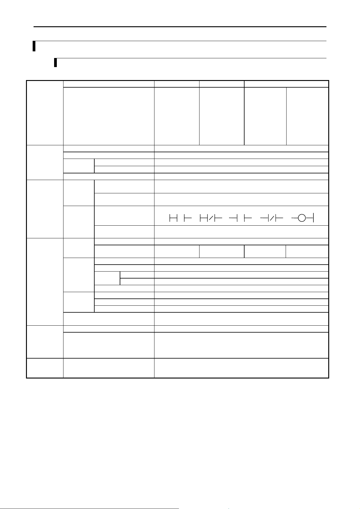
3.3.1 Calculation Specifications
The calculation specifications of the PLC are described below.
Model Name 10-point type 14-point type 23/28-point type
Control
specifications
Operation
processing
specifications
Type
CPU
Processing system
Processing
speed
User program memory
Instruction
language
Ladder Basic instructions
Basic instructions
Application instructions
Basic instructions
Arithmetic instructions
Application instructions
EH-D10DT
EH-D10DTP
EH-D10DR
39 types such as LD, LDI, AND, ANI, OR, ORI, ANB, ORB, OUT, MPS,
62 types (arithmetic, application, control, FUN command etc.)
EH-D14DT
EH-D14DTP
EH-A14DR
EH-D14DR
EH-A14AS
32-bit RISC processor
Stored program cyclic system
0.9 µs / instruction
Several 10 µs / instruction
3 k steps max. (FLASH memory)
MRD, MPP, etc.
39 types, such as
EH-A23DRP
EH-A23DRT
EH-D23DRP
EH-D28DT
EH-D28DTP
EH-A28DRP
EH-A28DRT
EH-A28DR
EH-D28DRP
EH-D28DRT
EH-D28DR
EH-A28AS
Arithmetic instructions
Application instructions
I/O
processing
specifications
Peripheral
equipment
Maintenance
functions
*1: The same numbers cannot be used with the timer counter.
*2: Only timers numbered 0 to 63 can use 0.01 s for their timer base.
External
I/O
Internal
output
Timer
counter
Edge detection
Program system
Peripheral unit
Self-diagnosis
I/O processing system
Maximum number of
points
Bit
Word
Special
Bit/word shared
Number of points
Timer set value
Counter set value
Bit
Word
10 points 126 points 135 points 140 points
0 to 65,535, timer base 0.01 s, 0.1 s, 1 s (0.01s has maximum 64 points *2)
Instruction language programmer and form graphic display programmer cannot
PLC error (LED display): Microcomputer error, watchdog timer error, memory
error, program error, system ROM/RAM error, scan time monitoring, battery
voltage low detection, etc.
62 types (arithmetic, application, control, FUN command etc.)
Refresh processing
1,984 points (R0 to R7BF)
4,096 words (WR0 to WRFFF)
64 points (R7C0 to R7FF)
512 words (WRF000 to WRF1FF)
16,384 points, 1,024 words (M0 to M3FFF, WM0 to WM3FF)
256 points (TD + CU) *1
1 to 65,535 times
512 points (DIF0 to DIF511: Decimal)
+ 512 points (DFN0 to DFN511: Decimal)
Instruction language, ladder diagram
Programming software
(LADDER EDITOR DOS version/Windows® version, Pro-H)
be used.
3-6
Page 23
Chapter 3 Function and Performance Specifications
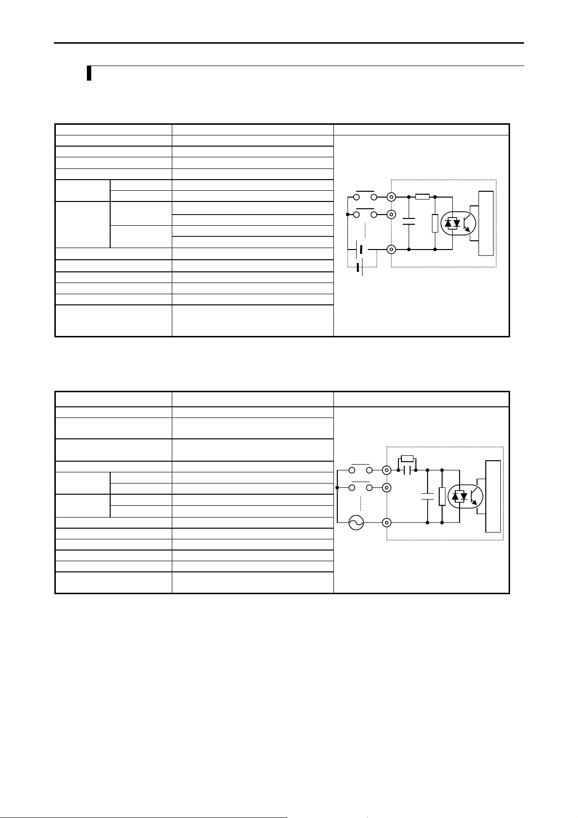
3.3.2 Input Specifications
The input circuit consists of DC input and AC input, with the following specifications.
(1) DC input
Item Specification Circuit diagram
Input voltage 24 V DC
Allowable input voltage range 0 to 30 V DC
Input impedance
Input current 7.5 mA typical
ON voltage 15 V DC (min) / 4.5 mA (max)Operating
voltage
Input lag
OFF voltage 5 V DC (max) / 1.5 mA (max)
OFF → ON
ON → OFF
Basic unit : 0.5 to 20 ms (configurable)
Exp. unit : 0.5 ms or less
Basic unit : 0.5 to 20 ms (configurable)
Exp. unit : 0.5 ms or less
Number of input points
Number of common
Polarity None
Insulation system Photocoupler insulation
Input display LED (green)
External connection 10-point type: fixed type terminal block
14-, 23-, 28-point types: Removable type
*1: Common terminals are separated each other.
Approx. 2.8 kΩ
See Chapter 4
See Chapter 4
screw terminal block (M3)
0
Internal circuit
1
C
(2) AC input
Item Specification Circuit diagram
Input voltage 100 to 120 V AC
Allowable input voltage range 85 to 132 V AC
50 -5 % to 60 +5 % Hz
Input impedance
Input current Approx. 7 mA RMS (100 V AC/60 Hz)
ON voltage 80 V AC (min.) 4.5 mAOperating
voltage
Input lag
Number of input points See Chapter 4.
Number of common See Chapter 4.
Polarity None
Insulation system Photocoupler insulation
Input display LED (green)
External connection 14-, 28-point types: Removable type screw
*1: Delay by hardware only. Delay by digital filter (software filter) 0.5 to 20 ms is not included.
*2: Common terminals are separated each other.
OFF voltage 30 V AC (max.) 2 mA
OFF → ON
ON → OFF
Approx. 14.6 kΩ (60 Hz)
Approx. 17.6 kΩ (50 Hz)
25 ms (max.) *1
30 ms (max.) *1
terminal block (M3)
0
1
C
Internal circuit
3-7
Page 24
Chapter 3 Function and Performance Specifications
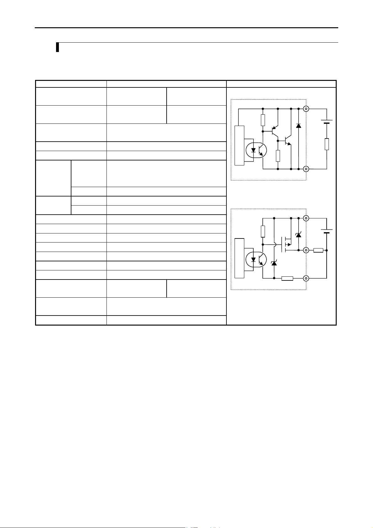
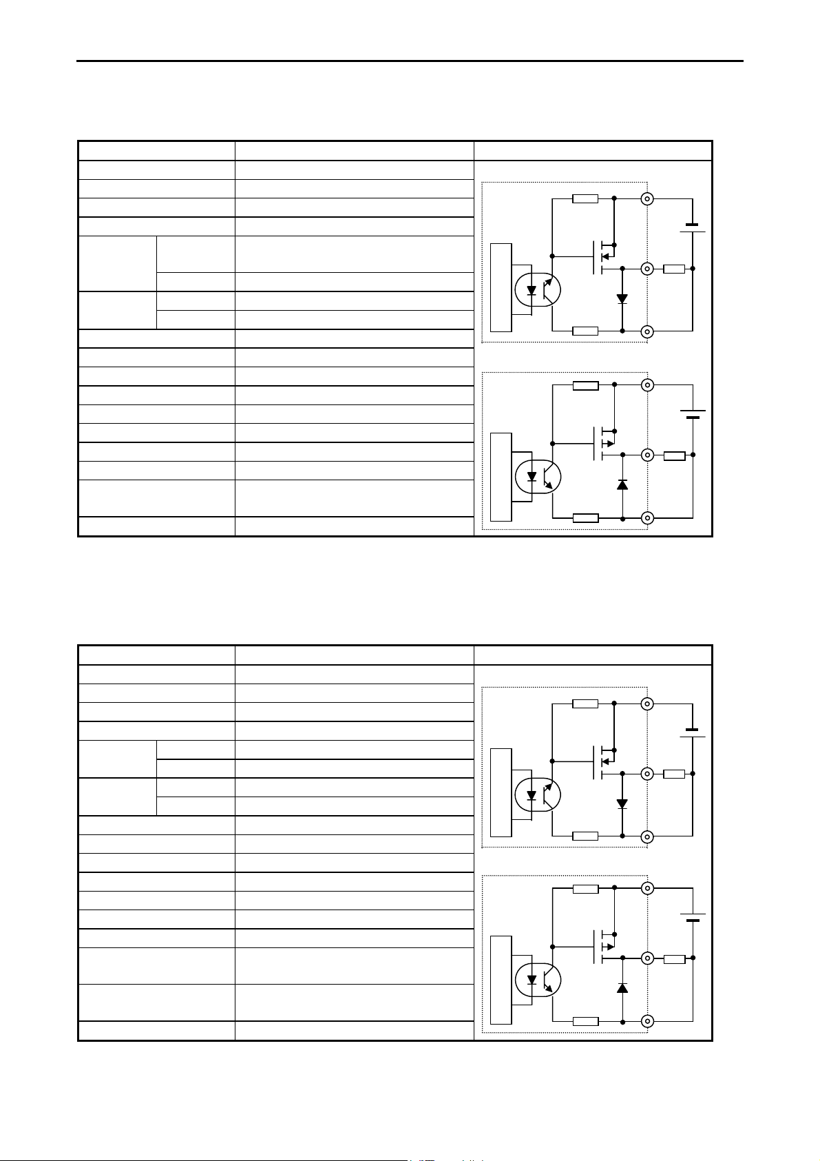
3.3.3 Output Specifications
(1) DC output
(Y100 of EH-*23DRP/A23DRT/*28DRP/*28DRT)
Item Specification Circuit diagram
Type EH-A23DRT
EH-*28DRT
Y100 output specifications Transistor output
(sink type)
EH-*23DRP
EH-*28DRP
Transistor output
(source type)
Rated load voltage 24 / 12 / 5 V DC
24 V DC +20 %, -80 %
Minimum switching current 1 mA
Leak current 0.1 mA (max)
Maximum
load current
1 circuit 0.75 A 24 V DC
0.5 A 12 V DC
0.25 A 5 V DC
1 common 0.75 A
OFF → ON 0.1 ms (max) 24 V DC 0.2 AOutput
response time
ON → OFF 0.1 ms (max) 24 V DC 0.2 A
Number of output points 1
Number of common 1
Surge removing circuit None
Fuse None
Insulation system Photocoupler insulation
Output display LED (green)
External connection Removable type screw terminal block (M3)
External power supply *1
Not necessary 30 to 16 V DC
to V terminal
Insulation 1500 V or more (external-internal)
500 V or more (external-external)
Output voltage drop 0.3 V DC (max)
*1: It is necessary to supply 16 to 30 V DC between the V and C terminals externally for the source type.
The sink type operates by load power supply only. See “4.6 Terminal Layout and Wiring” for the details.
Sink type (23/28DRT)
Internal circuit
Source type (23/28DRP)
Internal circuit
0
C0
V0
0
C0
3-8
Page 25
Chapter 3 Function and Performance Specifications
(2) DC output: LCDC-Low Current
(All points of EH-D10DT/DTP, Y102-Y105 of EH-D14DT/DTP, Y102-Y109 of EH-D28DT/DTP,
Y*018-Y*021 of EH-D14EDT/D14EDTP)
Item Specification
Output specification Transistor output
Sink type (EH-D**DT)
Rated load voltage 24/12 V DC (+10 %, -15 %)
Minimum switching current 1 mA
Leak current 0.1 mA (max)
Maximum
load current
1 circuit 0.75 A 24 V DC
0.5 A 12 V DC
Internal circuit Internal circuit
1 common 3 A
OFF → ON 0.1 ms (max) 24 V DC 0.2AOutput
response time
ON → OFF 0.1 ms (max) 24 V DC 0.2A
Number of output points See Chapter 4.
Number of common See Chapter 4.
Source type (EH-D**DTP)
Surge removing circuit None
Fuse None
Insulation system Photocoupler insulation
Output display LED (green)
Internal circuit
External connection Removable type screw terminal block (M3)
Externally supplied power *1 30 to 12 V DC
Insulation 1500 V or more (external-internal)
500 V or more (external-external)
Output voltage drop 0.3 V DC (max)
*1: It is necessary to supply 12 to 30 V DC between the V and C terminals externally. See “4.6 Terminal Layout and Wiring.”
Circuit diagram
V0
0
C0
V0
0
C0
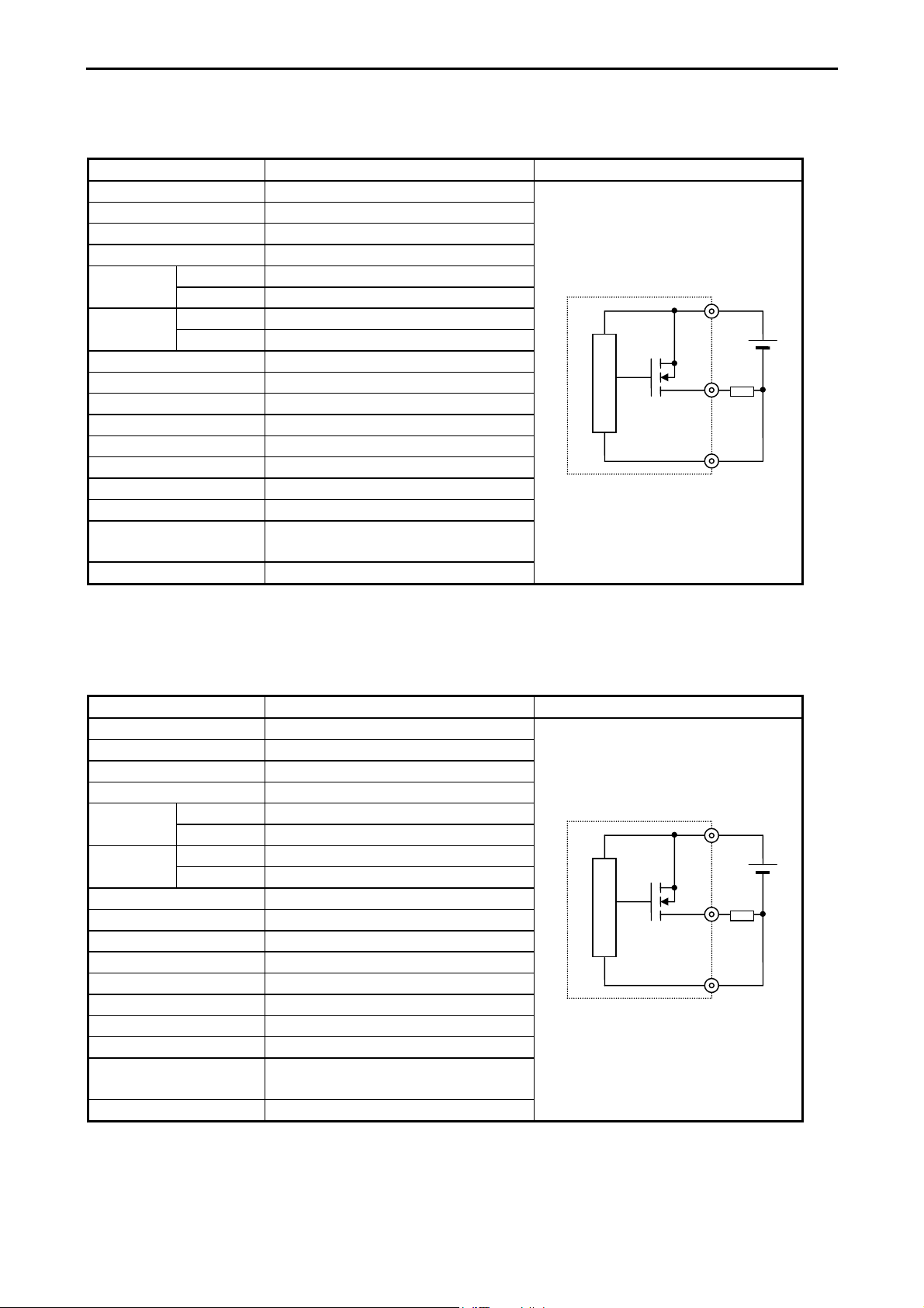
(3) DC output: HCDC-High Current
Y100,Y101
(
Y*016, Y*017
of EH-D14DT/DTP,
of EH-D14EDT/D14EDTP)
Item Specification
Output specification Transistor output
Rated load voltage 24/12 V DC (+10 %, -15 %)
Minimum switching current 1 mA
Leak current 0.1 mA (max)
1 circuit 1A 24 V DCMaximum
load current
1 common 3 A
OFF → ON 0.1 ms (max) 24 V DC 0.2AOutput
response time
ON → OFF 0.1 ms (max) 24 V DC 0.2A
Number of output points See Chapter 4.
Number of common See Chapter 4.
Surge removing circuit None
Fuse None
Insulation system Photocoupler insulation
Output display LED (green)
External connection Removable type screw terminal block (M3)
Externally supplied power *1 30 to 12 V DC
Insulation 1500 V or more (external-internal)
Output voltage drop 0.3 V DC (max)
*1: It is necessary to supply 12 to 30 V DC between the V and C terminals externally. See “4.6 Terminal Layout and Wiring.”
Y100, Y101, Y110, and Y111
500 V or more (external-external)
of EH-D28DT/DTP,
Circuit diagram
Sink type (EH-D**DT)
V0
Internal circuit
0
C0
Source type (EH-D**DTP)
V0
0
C0
3-9
Page 26
Chapter 3 Function and Performance Specifications
(4) DC output (ESCP type): HCDC-High Current
(Y100,Y101 of EH-D14DTPS, Y100-Y103 of D28DTPS)
Y*016,Y*017 of EH-EDTPS, Y*016-Y*019 of EH-D28EDTPS)
Item Specification
Output specification Transistor output
Rated load voltage 24/12 V DC (+10 %, -15 %)
Minimum switching current 10 mA
Leak current 0.1 mA (max)
load current
1 circuit 1 AMaximum
1 common 3 A
Source type (EH-D**DTPS)
OFF → ON 0.05 ms (max) 24 V DC 0.2AOutput
response time
ON → OFF 0.05 ms (max) 24 V DC 0.2A
Number of output points See Chapter 4.
Number of common See Chapter 4.
Surge removing circuit None
Fuse None
Insulation system Photocoupler insulation
Output display LED (green)
External connection Removable type screw terminal block (M3)
Externally supplied power *1 30 to 12 V DC
Insulation 1500 V or more (external-internal)
500 V or more (external-external)
Output voltage drop 0.3 V DC (max)
*1: It is necessary to supply 12 to 30 V DC between the V and C terminals externally. See “4.6 Terminal Layout and Wiring.”
Circuit diagram
V0
Internal circuit
0
C0
(5) DC output (ESCP type): LCDC-Low Current
(Y102-Y105 of EH-D14DTPS, Y104-Y111 of EH-D28DTPS
Y*018-Y*021
of EH-D14EDTPS,
Item Specification
Output specification Transistor output
Rated load voltage 24/12 V DC (+10 %, -15 %)
Minimum switching current 10 mA
Leak current 0.1 mA (max)
1 circuit 0.7 AMaximum
load current
1 common 3 A
OFF → ON 0.5 ms (max) 24 V DC 0.2AOutput
response time
ON → OFF 0.5 ms (max) 24 V DC 0.2A
Number of output points See Chapter 4.
Number of common See Chapter 4.
Surge removing circuit None
Fuse None
Insulation system Photocoupler insulation
Output display LED (green)
External connection Removable type screw terminal block (M3)
Externally supplied power *1 30 to 12 V DC
Insulation 1500 V or more (external-internal)
Output voltage drop 0.3 V DC (max)
*1: It is necessary to supply 12 to 30 V DC between the V and C terminals externally. See “4.6 Terminal Layout and Wiring.”
Y*020-Y*027
of EH-D28EDTPS)
500 V or more (external-external)
Circuit diagram
Source type (EH-D**DTPS)
V0
Internal circuit
0
C0
3-10
Page 27
Chapter 3 Function and Performance Specifications
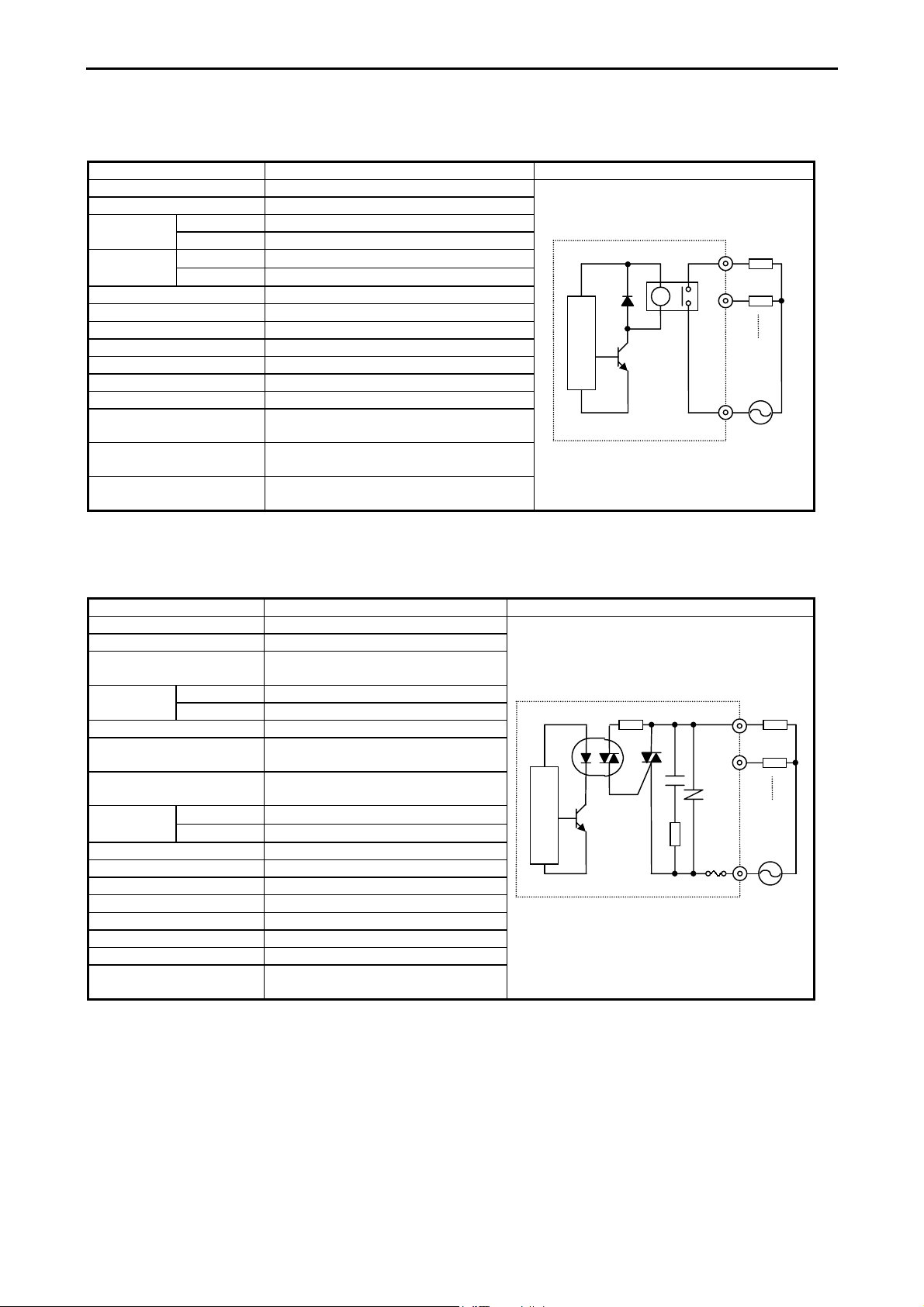
(6) Relay output
Item Specification Circuit diagram
Rated load voltage 5 to 250 V AC, 5 to 30 V DC
Minimum switching current 1 mA
1 circuit 2 A (24 V DC, 240 V AC)Maximum
load current
Output
response time
Number of output points See Chapter 4.
Number of common See Chapter 4.
Surge removing circuit None
Fuse None
Insulation system Relay insulation
Output display LED (green)
External connection Removable type screw terminal block (M3)
Externally supplied power
(for driving the relays)
Contact life *1 20,000,000 times (mechanical)
Insulation 1500 V or more (external-internal)
*1: Refer to the Life curve of relay contacts in Chapter 10 for the details.
1 common 5 A
OFF → ON
ON → OFF
15 ms (max)
15 ms (max)
Not necessary
200,000 times (electrical: 2 A)
500 V or more (external-external)
0
Internal circuit
1
C
(7) AC output (SSR)
Item Specification Circuit diagram
Output specification Triac output
Rated voltage 100/240 V AC
Output voltage 100 –15 % to 240 +10 % V AC
50 –5 % to 60 +5 % Hz
1 circuit 0.5 A 240 V ACMaximum
load current
Minimum load current 100 mA
Maximum leakage current 1.8 mA 115 V AC(max)
Maximum inrush current 5 A (at 1 cycle or less)/point
Maximum
delay time
Output common See Chapter 4.
Polarity See Chapter 4.
Insulation system Phototriac insulation
Fuse *2 Used
Surge removing circuit Sunabar circuit + varistor
External connection Removable terminal block
Voltage drop 1.5 V RMS (max)
Insulation 1500 V or more (external-internal)
*2: It is necessary to repair the module if the load short-circuits and causes the fuse to melt.
Note that the fuse cannot be replaced by users.
1 common 2 A
3.5 mA 230 V AC(max)
10 A (at 1 cycle or less)/common
Off → On
On → Off
1 ms or less
1 ms + 1/2 cycle or less
500 V or more (external-external)
Internal circuit
0
1
C
3-11
Page 28

Chapter 3 Function and Performance Specifications
3.3.4 High-Speed Counter Specifications
Single phase Two phase
Available input X0, X2, X4, X6 X0 and X2 in pair
Input voltage ON 15 V
OFF 5 V
Count pulse width
Maximum count frequency 10 kHz each channel
Count register 16 bits
Coincidence output Allowed
On/Off-preset Allowed
Upper/lower limit setting Not allowed
Preload/strobe Allowed
Since 10 points type does not have input X6, counter channel is up to 3 ch.
100 µs
3.3.5 PWM Output/Pulse Train Output Specifications
23-point and 28-point type
Relay Output
Available outputs Y100 (optional) Y100-Y103 (optional)
Load voltage 5/12/24 V 12/24 V
Minimum load current 1 mA
PWM max. output frequency *1 2 kHz total channels
Pulse train max. output frequency *1 5 kHz total channels
Pulse acceleration/deceleration By FUN 151.
*1: Relay outputs cannot keep up with high frequencies; these outputs should be used at the operating frequency upon confirmation.
10/14/28-point
Transistor Output
3.3.6 Analogue Input Specifications
Module type 23 points module Analog exp. unit
Input channel WX30, WX31 WX u01 - WX u04
(u : unit number)
Input range
Resolution 12 bits
Accuracy ±1 % of full scale
Linearity Max. +/-3 units
Current input impedance
Voltage input impedance
Input delay time 20 ms
Channel to internal circuit insulation Not insulated Insulated
Channel-to-channel insulation Not insulated
0-10 V (10.24V max.) 0-10V (10.24V max.)
-10 to +10V (±10.24V max.)
0-20 mA (20.48 mA max.) 0-20 mA (20.48 mA max.)
- 4-20 mA (20.38 mA max.)
Approx. 249 Ω
Approx. 100 kΩ Approx. 200 kΩ
3-12
Page 29
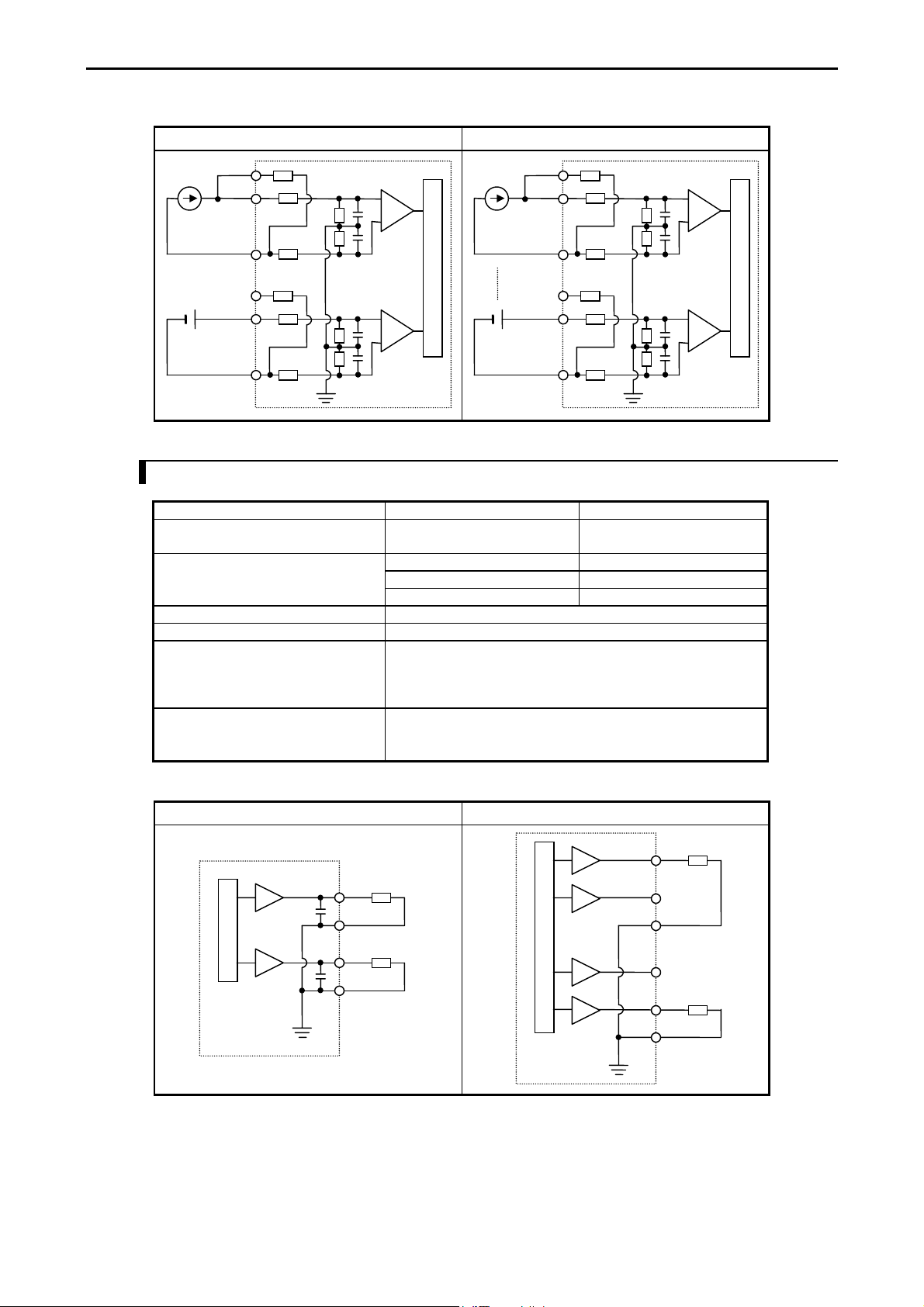
Chapter 3 Function and Performance Specifications
Circuit diagram (23 points type) Circuit diagram (Analog expansion unit)
Current
Voltage
IN2JP
IN2+
Internal circuit
IN2-
IN1JP
IN1+
IN1-
IN4JP
IN4+
Current
IN4-
IN1JP
IN1+
Voltage
IN1-
3.3.7 Analogue Output Specifications
Module type 23 points type module Analog exp. unit
Output channel WY40 WY u06, WY u07
(u : unit number)
Output range
Resolution 12 bits
Accuracy ±1 % of full scale
Current output
Allowable load
Output allowable capacity
Output allowable inductance
Voltage output
Allowable load
Output allowable impedance
0-10V (10.24V max.) 0-10V (10.24V max.)
0-20mA (20.48mA max.) 0-20mA (20.48mA max.)
4-20mA (20.38mA max.)
10 to 500 Ω
Maximum 2000 pF
Maximum 1 H
Maximum 10 kΩ
Maximum 1 µF
Internal circuit
Circuit diagram (23 points type) Circuit diagram (Analog expansion unit)
Voltage
Internal circuit
Voltage
Current
Internal circuit
IO7
IO6
Current
3-13
Page 30

Chapter 3 Function and Performance Specifications
3.3.8 Potentiometer Analogue Input Specifications
Number of potentiometer inputs 2
Stored in
Input range 0-1023 (H0-H3FF)
Resolution 10 bits
Input filter By user settings
Ch.1 : WRF03E, Ch.2 WRF03F
3.3.9 Interrupt Input Specifications
Input that can be used X1, X3, X5, X7 (by user settings)
ON 15 VInput voltage
OFF 5 V
3.3.10 Backup
(1) Battery
Data memory (retentive area) can be kept by EH-MBAT battery as below.
Battery life time (total power off time) [Hr] *
Guaranteed value (Min.) @55°C Actual value (Max.) @25°C
9,000 18,000
* Battery life time has been changed since Oct. 2002 production (MFG NO.02Jxx) due to hardware modification.
Battery can be mounted inside of front cover.
Battery is available only for 23-point and 28-point types.
If the calendar clock function is used with the 23-point or 28-point type, be sure to use the battery.
(2) Capacitor
14-point type: Data can be kept for 72 hours (at 25 °C) by the capacitor.
23 and 28-point types: Data can be kept for 24 hours (at 25 °C) by the capacitor.
Please note that data memory of 10 point type cannot be retained.
3.3.11 Expansion
• Up to 4 times of expansion units can be installed.
• 14 points and 28 points digital units, and 4ch. input / 2 ch. output analog expansion units available.
• A cable with a length of up to 1 m can be used to connect between units.
• The total extension cable length can be up to 2 m (from the basic unit to the expansion unit at the end).
• The 10-point type unit cannot be expanded.
3-14
Page 31

Chapter 3 Function and Performance Specifications
3.3.12 Clock Function
23-point and 28-point types have calendar function. This can be operated either by internal output area or task code.
* 10-point and 14-point types do not have this function.
(1) Reading the clock data
By turning on the read request (R7F8), the clock data is read out in the reading value area (WRF01B to WRF01F).
(2) Writing the clock data
By turning on the write request (R7F9), the clock data stored in writing value area (WRF01B to WRF01F) is written
to the current data area (WRF00B to WRF00F). If the data is wrong, error flag (R7BF) will turn on. If data is right,
clock data will be written and writing flag R7FB will turn off.
(3) Adjusting the clock data ± 30 seconds
By turning on the ± 30 seconds adjustment request (R7FA), one of the following operations is performed depending
on the second value:
• If the second digits are 00 to 29, the second digits are set to 00.
• If the second digits are 30 to 59, the minute is incremented by 1 and the second digits are set to 00.
(4) Special internal output definitions
• Operation bits
I/O number Name Description
R7F8 Request to read calendar and
clock data
R7F9 Request to write calendar and
clock data
R7FA
R7FB Calendar and clock setting data
Clock ± 30 seconds adjustment
request
error
Calendar and clock data is read out to
WRF01B-F01F.
Calendar and clock data in WRF01B-F01F is
written to the current data in WRF00B-F00F.
Sets the second digits of the RTC to 00.
Turns on when the setting data is abnormal.
• Current data monitor area : Current data of the clock given always (all BCD data).
I/O number Name Description
WRF00B Year 4-digit year [yyyy]
WRF00C Month and date [mmdd]
WRF00D Day of the week 0 to 6 : Sunday to Saturday
WRF00E Hour and minute [hhmm] (24-hour system).
WRF00F Second [00ss]
• Reading/writing area : Clock data to be read or written.
(All BCD data)
I/O number Name Description
WRF01B Year 4-digit year [yyyy]
WRF01C Month and date [mmdd]
WRF01D Day of the week 0 to 6 : Sunday to Saturday
WRF01E Hour and minute [hhmm] (24-hour system).
WRF01F Second [00ss]
Note 1: The day of the week data is expressed as follows.
0: Sunday, 1: Monday, 2: Tuesday, 3: Wednesday, 4: Thursday, 5: Friday, 6: Saturday
3-15
Page 32

Chapter 3 Function and Performance Specifications
3.3.13 Power Supply for Sensor
The 24 V terminal at the input terminal part can supply current to external equipment (not for all units).
If this terminal is used as the power supply for the input part of this unit, the remaining can be used as power supply for the
sensors.
The following current (I) can be supplied as power supply for the sensors.
(1) EH-*14*** (14-point type basic unit)
EH-*14E*** (14-point type extension unit)
I = 350 mA – (7.5 mA x number of input points that are turned on at the same time)
(2) EH-A28DR* (28-point type basic unit)
EH-A23DR*** (23-point type basic unit)
I = 280 mA – (7.5 mA x number of input points that are turned on at the same time)
3-16
Page 33

Chapter 4 Product lineup and wiring
Chapter 4 Product lineup and wiring
4.1 Product lineup
(1) Basic units
Table 4.1 Product lineup list
Type Specifications
EH-D10DT
EH-D10DTP
EH-D10DR
EH-D14DT
EH-D14DTP
EH-A14DR
EH-D14DR
EH-A14AS
EH-D23DRP
EH-A23DRT
EH-A23DRP
EH-D28DT
EH-D28DTP
EH-D28DTPS
EH-D28DRT
EH-D28DRP
EH-A28DRT
EH-A28DRP
EH-A28DR
EH-A28AS
EH-D14EDT
EH-D14EDTP
EH-D14EDTPS
EH-D14EDR
EH-A14EDR
EH-D28EDT
EH-D28EDTPS
EH-D28EDR
EH-A28EDR
EH-D6EAN Expansion unit, DC power, Analog input × 4, Analog output × 2
EH-A6EAN Expansion unit, AC power, Analog input × 4, Analog output × 2
DC power, DC input × 6, Transistor (sink) output × 4
DC power, DC input × 6, Transistor (source) output × 4
DC power, DC input × 6, Relay output × 4
DC power, DC input × 8, Transistor (sink) output × 6
DC power, DC input × 8, Transistor (source) output × 6
AC power, DC input × 8, Relay output × 6
DC power, DC input × 8, Relay output × 6
AC power, AC input × 8, SSR output × 6
DC power, DC input × 13, Relay output × 9, Transistor output (source) × 1,
Analog input × 2, Analog output × 1
AC power, DC input × 13, Relay output × 9, Transistor output (sink) × 1,
Analog input × 2, Analog output × 1
AC power, DC input × 13, Relay output × 9, Transistor output (source) × 1,
Analog input × 2, Analog output × 1
DC power, DC input × 16, Transistor (sink) output × 12
DC power, DC input × 16, Transistor (source) output × 12
DC power, DC input × 16, Transistor (source) output (ESCP) × 12
DC power, DC input × 16, Relay output × 11, Transistor output (sink) × 1
DC power, DC input × 16, Relay output × 11, Transistor output (source) × 1
AC power, DC input × 16, Relay output × 11, Transistor output (sink) × 1
AC power, DC input × 16, Relay output × 11, Transistor output (source) × 1
AC power, DC input × 16, Relay output × 12
AC power, AC input × 16, SSR output × 12
Expansion unit, DC power, DC input × 8, Transistor (sink) output × 6
Expansion unit, DC power, DC input × 8, Transistor (source) output × 6
Expansion unit, DC power, DC input × 8, Transistor (source) output (ESCP) × 6
Expansion unit, DC power, DC input × 8, Relay output × 6
Expansion unit, AC power, DC input × 8, Relay output × 6
Expansion unit, DC power, DC input × 16, Transistor (sink) output × 12
Expansion unit, DC power, DC input × 16, Transistor (source) output (ESCP) × 12
Expansion unit, DC power, DC input × 16, Relay output × 12
Expansion unit, AC power, DC input × 16, Relay output × 12
I/O assignment
symbol
X48/Y32/empty16
X48/Y32/empty16
X48/Y32/empty16
X48/Y32/empty16
X48/Y32/empty16
X48/Y32/empty16
X48/Y32/empty16
X48/Y32/empty16
X48/Y32/
empty16/WX4/WY4
X48/Y32/
empty16/WX4/WY4
X48/Y32/
empty16/WX4/WY4
X48/Y32/empty16
X48/Y32/empty16
X48/Y32/empty16
X48/Y32/empty16
X48/Y32/empty16
X48/Y32/empty16
X48/Y32/empty16
X48/Y32/empty16
X48/Y32/empty16
B1/1
B1/1
B1/1
B1/1
B1/1
B1/1
B1/1
B1/1
B1/1
FUN 0
FUN 0
Each digit in the type name has the following meaning:
EH - D
28
D T P
[None]: Sink, T: Sink, P: Source (except in the cases of relay output and SSR output)
R: Relay output, T: Transistor (DC) output, S: SSR (AC) output
D: DC input, A: AC input
[None]: Basic unit, E: Expansion unit
10: 10-point type, 14: 14-point type, 23: 23-point type, 28: 28-point type
A: AC power supply type, D: DC power supply type
4-1
Page 34

Chapter 4 Product lineup and wiring
(2) Peripheral Units
Table 4.2 List of peripheral units
Product Form Specification Remarks
Graphic input
device support
software
Note: HI-LADDER (attached to the GPCL01H) may also be used.
However, HL-GPCL and HI-LADDER cannot be used for the 10-point type.
and expansion unit
Conversion cable for
connecting peripheral units
Peripheral equipment GPCB02H Length: 2 m, between CPU and graphic input unit
*: Required when connecting the MICRO-EH with PC98, IBM PC/AT compatible PC or other system using one of the cables
marked with **.
HL-GPCL Ladder diagram/Instruction language editor LADDER EDITOR (for GPCL)
HL-PC3 Ladder diagram/Instruction language editor LADDER EDITOR (for PC98
series) with CPU connection cable
HL-AT3E Ladder diagram/Instruction language editor LADDER EDITOR (for PC/AT
compatible personal computer)
HLW-PC3 Ladder diagram/Instruction language editor LADDER EDITOR (for Windows®
95/NT 4.0)
HLW-PC3E Ladder diagram/Instruction language editor LADDER EDITOR (for Windows®
95/98/NT 4.0)
Pro-H HITACHI H-series PLC Programming Software According to IEC 61131-3 (for
Windows® 95/98/NT 4.0)
(3) Connection Cables
Table 4.3 List of connection cables
Product Form Specification Remarks
EH-MCB10 Length: 1 m (basic unit–exp. unit, exp. unit - exp. unit) Total 2 mCable for connecting basic unit
EH-MCB05 Length: 0.5 m (basic unit–exp. unit, exp. unit - exp. unit) Total 2 m
EH-MCB01 Length: 0.1 m (basic unit–exp. unit, exp. unit - exp. unit) Total 2 m
EH-RS05 Length: 0.5 m *
GPCB05H Length: 5 m, between CPU and graphic input unit
GPCB15H Length: 15 m, between CPU and graphic input unit
CBPGB Length: 2 m, between graphic input unit and printer
LP100 Length: 2 m, between graphic input unit and kanji printer
KBADPTH Length: 15 m, between graphic input unit and JIS keyboard
PCCB02H Length: 2 m, between CPU and PC98 series **
WPCB02H Length: 2 m, between CPU and PC98 series (25-pin) **
WVCB02H Length: 2 m, between CPU and DOS/V (9-pin) **
EH-VCB02 Length: 2 m, between CPU (8P modular terminal) and DOS/V
(9-pin)
(4) Others
Model Usage Remarks
EH-MBAT Lithium battery
4-2
Page 35

4.2 10-Point Basic Unit
Chapter 4 Product lineup and wiring
Name and function of each part
9] Mounting hole
4] Serial port
8] Power terminal
5] RUN input
Type EH-D10DT, EH-D10DTP, EH-
D10DR
6] Input terminals
1] POW LED
2] OK LED
3] RUN LED
7] Output terminals
10] DIN rail installation clip
No. Item Detailed explanation Remarks
Explanation of operation Operations are performed according to the contents of the program created
by the user.
The programming unit connected to the CPU module communication port
writes and reads the user programs.
Memory is installed inside the CPU module in which the user programs and
internal output information are stored.
1] POW LED Lighting when the power is supplied.
2] OK LED Lighting at normal operation. See Chapter 12.
3] RUN LED Lighting at RUN status.
4] Serial port 1 Serial port for connecting the peripheral units. Communication speed is
See Chapter 11.
fixed as 4800 bps.
The communication specification is set to port 1.
5] RUN input External input to control the PLC’s RUN/STOP.
See Chapter 10.
When 24 V DC is loaded to the RUN terminal and common terminal (C),
the PLC is set to the RUN state.
6] Input terminals Terminals for wiring the external input units.
One piece of AWG14 to AWG22 (2.1 to 0.36 mm
AWG16 to AWG22 (1.3 to 0.36 mm
2
) per terminal may be wired.
2
) or two pieces of
7] Output terminals Terminals for connecting the external load. The wiring specification is the
See Chapter 10.
See Chapter 10.
same as for the input terminals.
8] Power terminal Terminal for connecting the power supply. The wiring specification is the
See Chapter 10.
same as for the input terminals.
9] Mounting hole Used when installing the PLC directly on a board with screws See Chapter 10.
10] DIN rail
Used when installing the PLC on a DIN rail See Chapter 10.
installation clip
4-3
Page 36

4.3 14-Point Basic Unit
Chapter 4 Product lineup and wiring
Name and function of each part
10] Terminal cover
11] Mounting hole
4] Serial port cover
Type EH-*14***
5] Input terminals
1] POW LED
2] OK LED
3] RUN LED
8] Expansion
connector cover
9] DIP SW cover
6] Output terminals
12] DIN rail installation clip
7] Power terminal
No. Item Detailed explanation Remarks
Explanation of operation Operations are performed according to the contents of the program created
by the user.
The programming unit connected to the CPU module communication port
writes and reads the user programs.
Memory is installed inside the CPU module in which the user programs and
internal output information are stored.
1] POW LED Lighting when the power is supplied.
2] OK LED Lighting at normal operation. See Chapter 12.
3] RUN LED Lighting at RUN status.
4] Serial port cover Cover for the connector for connecting
peripheral units and the RUN switch.
When the cover is opened, the RUN switch,
STOP
RUN
VR1 VR2
See Chapters 8 and 11.
potentiometers (VR), and RS-232C serial port 1
(PORT 1) can be used.
The communication specification is set to port 1.
PORT1
5] Input terminals Terminals for wiring the external input units.
Recommended terminals are shown in the
figure to the right.
One piece of AWG14 to AWG22 (2.1 to
0.36 mm
AWG22 (1.3 to 0.36 mm
2
) or two pieces of AWG16 to
2
) per terminal may
6
6
See Chapter 10.
(Mak e su re t hat the ter minals w ill not
disengage due to loose screws.)
(Recommended)
be wired.
6] Output terminals Terminals for connecting the external load.
See Chapter 10.
The wiring specification is the same as for the input terminals.
7] Power terminal Terminal for connecting the power supply.
See Chapter 10.
The wiring specification is the same as for the input terminals.
8] Expansion cover Cover for the expansion connector See Chapter 10.
9] DIP SW cover Cover for the DIP switches
See Chapter 11.
When the cover is opened, the DIP switches are exposed. These DIP
switches are used to set the communication speed of serial port 1 and the
modem connection.
10] Terminal cover Cover for terminals
11] Mounting hole Used when installing the PLC with screws See Chapter 10.
12] DIN rail
Used when installing the PLC on a DIN rail See Chapter 10.
installation clip
4-4
Page 37

4.4 23-Point and 28-Point Basic Unit
Chapter 4 Product lineup and wiring
Name and function of each part
Type
EH-*23***
EH-*28***
10] Terminal cover
13] RS-485 port cover
11] Mounting
hole
4] Serial port cover
5] Input terminals
1] POW LED
2] OK LED
3] RUN LED
8] Expansion
connector cover
9] DIP SW cover
6] Output terminals
12] DIN rail installation clip
7] Power terminal
No. Item Detailed explanation Remarks
Explanation of operation Operations are performed according to the contents of the program created
by the user.
The programming unit connected to the CPU module communication port
writes and reads the user programs.
Memory is installed inside the CPU module in which the user programs and
internal output information are stored.
1] POW LED Lighting when the power is supplied.
2] OK LED Lighting at normal operation. See Chapter 12.
3] RUN LED Lighting at RUN status.
4] Serial port cover Cover for the connector for connecting
peripheral units and the RUN switch.
When the cover is opened, the RUN switch,
STOP
RUN
VR1 VR2
See Chapters 8 and 11.
potentiometers (VR), and RS-232C serial port 1
(PORT 1) can be used.
The communication specification is set to port 1.
PORT1
5] Input terminals Terminals for wiring the external input units.
Recommended terminals are shown in the figure
to the right.
One piece of AWG14 to AWG22 (2.1 to 0.36
2
mm
) or two pieces of AWG16 to AWG22 (1.3
to 0.36 mm
2
) per terminal may be wired.
6] Output terminals Terminals for connecting the external load.
6
6
See Chapter 10.
(Mak e su re t hat the ter minals w ill not
disengage due to loose screws.)
(Recommended)
See Chapter 10.
The wiring specification is the same as for the input terminals.
7] Power terminal Terminal for connecting the power supply.
See Chapter 10.
The wiring specification is the same as for the input terminals.
8] Expansion cover Cover for the expansion connector See Chapter 10.
9] DIP SW cover Cover for the DIP switches and the backup battery storage unit.
See Chapter 11.
When the cover is opened, the DIP switches are exposed. These DIP
switches are used to set the communication speed of serial port 1 and the
modem connection.
10] Terminal cover Cover for terminals
11] Mounting hole Used when installing the PLC with screws See Chapter 10.
12] DIN rail
Used when installing the PLC on a DIN rail See Chapter 10.
installation clip
13] RS-485 port cover Cover for RS-485 port. It is connected with a D sub 15-pin female
See Chapter 11.
connector. The communication specification is set to port 2.
4-5
Page 38

4.5 Expansion Unit
Chapter 4 Product lineup and wiring
Name and function of each part
9] Terminal cover
10] Mounting
hole
3] Expansion connector cover
(left side)
Type EH-*14ED** (same dimension as 14 pts. basic unit)
EH-*28ED** (same dimension as 28 pts. basic unit)
EH-*6EAN (same dimension as 14 pts. basic unit)
4] Input terminals
1] POW LED
2] OK LED
7] Expansion connector cover
(right side)
8] Dummy cover
5] Output terminals
11] DIN rail installation clip
6] Power terminal
Above picture is 14 points module
No. Item Detailed explanation Remarks
Explanation of operation Operations are performed according to the contents of the program created
by the user.
The programming unit connected to the CPU module communication port
writes and reads the user program.
Memory is installed inside the CPU module in which the user program and
internal output information are stored.
1] POW LED Lighting when the power is supplied.
2] OK LED Lighting at normal operation.
3] Expansion cover
(Left side)
4] Input terminals Terminals for wiring the external input units.
5] Output terminals Terminals for connecting the external load. The wiring specification is the
Cover for expansion connector
Used when connecting to the expansion cable from the front unit.
Recommended terminals are shown in the figure
to the right.
One piece of AWG14 to AWG22 (2.1 to 0.36
2
mm
) or two pieces of AWG16 to AWG22 (1.3
to 0.36 mm
2
) per terminal may be wired.
See Chapter 10.
See Chapter 10.
6
6
(Mak e su re t hat the ter minals w ill not
disengage due to loose screws.)
(Recommended)
See Chapter 10.
same as for the input terminals.
6] Power terminal Terminal for connecting the power supply. The wiring specification is the
See Chapter 10.
same as for the input terminals.
7] Expansion cover
(Right side)
Cover for expansion connector
Used when connecting to the next unit.
See Chapter 10.
8] Dummy cover Cover used as a dummy.
9] Terminal cover Cover for terminals
10] Mounting hole Used when installing the PLC with screws See Chapter 10.
11] DIN rail
Used when installing the PLC on a DIN rail See Chapter 10.
installation clip
4-6
Page 39

4.6 Terminal Layout and Wiring
10-point type
EH-D10DT, EH-D10DTP
* Since the DC input is bidirectional, it is possible to reverse the polarity of the power supply.
Chapter 4 Product lineup and wiring
Input power supply
24 V DC
54C032RUN 10NC
In case of EH-D10DTP
V0C032124 V 00 V
In case of EH-D10DT
Power supply
24V DC
EH-D10DR
* Since the DC input is bidirectional, it is possible to reverse the polarity of the power supply.
54C032RUN 10NC
C0321024V NC0V
Power supply
24V DC
Load power supply
12/24V DC
Input power supply
24V DC
Load power supply
24V DC
100-240V AC
4-7
Page 40

Chapter 4 Product lineup and wiring
14-point type
EH-A14DR, EH-D14DR
* Since the DC input is bidirectional, it is possible to reverse the polarity of the power supply.
Input power supply
24V DC
24+
0V 2
AC
AC C00C1
1
3
4
6 C1
0
C0
1
5
7
2
4 C2
3
5
AC power supply
100-240V AC
0V
24V
DC power supply
24V DC
EH-A14EDR, EH-D14EDR
* Since the DC input is bidirectional, it is possible to reverse the polarity of the power supply.
Input power supply
24V DC
Input
Output
Load power supply
24V DC,
100-240V AC
AC power supply
100-240V AC
DC power supply
24V DC
24+
0V 2
AC
AC C016C1
0V
24V
1
3
0
17
C0
18
4
5
20 C2
19
6 C1
7
21
Input
Output
Load power supply
24V DC,
100-240V AC
4-8
Page 41

EH-A14AS
Chapter 4 Product lineup and wiring
Power supply for input
100-115V AC
24+
0V 2
AC
AC 0
1
3
4
6 C1
0
NC
C0
1
C0
5
2
3
7
4 C1
5
Power supply
100-240V AC
EH-D14DTP
* Since the DC input is bidirectional, it is possible to reverse the polarity of the power supply.
Power supply for input
24V DC
1
3
4
24+
00V 2
0V
24V 1
0
C0
NC
2
6 C1
5
7
3
5 C0
4
V0
Input
Output
Load power supply
100-240V AC
Input
Output
Power supply
24V DC
EH-D14DT
(The input wiring is the same as EH-D14DTP.)
0V
24V 1
Power supply
24V DC
0
NC
Load power supply
12/24V DC
3
5 C0
2
4
V0
Output
Load power supply
12/24V DC
4-9
Page 42

Chapter 4 Product lineup and wiring
EH-D14EDTP
* Since the DC input is bidirectional, it is possible to reverse the polarity of the power supply.
24+
0V 2
24V 17
0
0V
Power supply
24V DC
EH-D14EDT
(The input wiring is the same as EH-D14EDTP.)
0V
24V 17
Power supply
24V DC
1
16
16
3
C0
NC2019
18
NC2019
18
4
6 C1
5
21 C0
21 C0
V0
V0
Input
7
Output
Load power supply
12/24V DC
Output
Load power supply
12/24V DC
4-10
Page 43

Chapter 4 Product lineup and wiring
23-point type
EH-A23DRP
* Since the DC input is bidirectional, it is possible to reverse the polarity of the power supply.
Power supply for
input, 24V DC
24+
0V 2
AC
AC C0
Power supply
100-240V AC
1
3
4
0
0
V0
C0
2
1
5
3
6 C1
7
4 5
C1
TR output power supply
8
C2 1110IN1-
C2 C4
9
6
7
C3
Load power supply
24V DC,
100-240V AC
16-30V DC
EH-A23DRT EH-D23DRP
(The input wiring is the same as EH-A23DRP.)
AC
AC C0
0
NC 2
1
Output
0V
24V
12
0
8
IN1+
9
V0 2
C0
IN1JP
C5
IC VC
Analog output
1
IN2-
IN2JP
IN2+
IO VO
Input
Output
+
-
Output
Power supply
100-240V AC
Analog voltage input
IN1+
IN1-
IN1JP
IN2-
IN2+
TR output power supply
16-30V DC
IN2JP
Analog current input
IN1+
IN1-
IN2-
IN1JP
TR output power supply
16-30V DC
In case of analog current input, please set
the following value in WRF06E.
WRF06E ch-0 ch-1
H0000 Voltage Voltage
H4000 Voltage Current
H8000 Current Voltage
HC000 Current Current
Please refer to Chapter 8-9.
IN2JP
IN2+
4-11
Page 44

Chapter 4 Product lineup and wiring
28-point type
EH-A28DRP
* Since the DC input is bidirectional, it is possible to reverse the polarity of the power supply.
9
11
24+
0V 2
1
0
3
4
C0
5
6 C1
7
10
8 C2
C2
12
13
15 C3
14
Power supply
for input 24V DC
Input
C3
AC 0
AC
C0
V0
2
1
3
4 5
C1
Power supply
100-240V AC
TR output power supply
16-30V DC
EH-A28DRT
(The input wiring is the same as EH-A28DRP.)
AC
AC C0
Power supply
100-240V AC
0
NC 2
1
EH-D28DRP
(The input wiring is the same as EH-A28DRP.)
Output
6
C2 C4
7
C3
8
C5
9
10 C6
11 C6
Output
Load power supply
24V DC, 100-240V AC
0V
24V C0
0
V0 2
1
Power supply
24V DC
TR output power supply
16-30V DC
EH-D28DRT
(The input wiring is the same as EH-A28DRP.)
0V
24V C0
Power supply
24V DC
0
NC 2
1
Output
Output
4-12
Page 45

EH-A28AS
Chapter 4 Product lineup and wiring
Power supply for input
100-115V AC
NC
NC 2
AC NC
AC
1
0
3
4
C0
1
2
C0
0
5
3
6 C1
7
4 C1
5
C2
C2 10
NC
NC 6
9
8
C2
C2
11
7
Power supply
100-240V AC
EH-D28DTP
* Since the DC input is bidirectional, it is possible to reverse the polarity of the power supply.
9
11
24+
0V 2
1
0
3
4
C0
5
6 C1
7
10
8 C2
C2
C3 13
C3
C3
C3
12
9 11
8 10
Load power supply
100-240V AC
13
12
15 C3
14
14
C3
15
Power supply for
input, 24V DC
Input
Output
Input
0V 0
24V
NC
1
3
2
4
5 C0
V0
Power supply
24V DC
EH-D28DT
(The input wiring is the same as EH-D28DTP.)
0V 0
24V
Power supply
24V DC
NC
1
3
2
4
5 C0
V0
C1
NC V1
C1
NC V1
V1
C1
V1
C1
6
8
7
9 10
Load power supply
12/24V DC
6
7
9 10
Load power supply
12/24V DC
NC 11
Output
NC 118
Output
4-13
Page 46

Chapter 4 Product lineup and wiring
p
p
EH-A28DR
* Since the DC input is bidirectional, it is possible to reverse the polarity of the power supply.
9
11
24+
0V 2
1
0
3
4
C0
5
6 C1
7
10
8 C2
C2
12
13
15 C3
14
C3
Power supply
for in
ut 24V DC
Input
AC 0
AC
C0
NC
2
1
3
4 5
C1
6
C2 C4
7
C3
8
Power supply
100-240V AC
EH-A28EDR
* Since the DC input is bidirectional, it is possible to reverse the polarity of the power supply.
9
11
23
C2
24
24+
0V 2
AC 1617NC
AC
1
0
C0
3
4
C0
18
5
20 21
19
6 C1
7
C1
10
8 C2
22
C3
C2 C4
C5
12
C5
11 C6
9
10 C6
Load power supply
24V DC, 100-240V AC
13
25
15 C3
14
C3
27 C6
26 C6
Output
Power supply
for in
ut 24V DC
Input
Output
Power supply
100-240V AC
Load power supply
24V DC, 100-240V AC
EH-D28DR EH-D28EDR
0V
24V C0
0
NC 2 0V
1
16
24V C0
NC 18
17
Output
4-14
Page 47

Analog expansion unit
g
p
EH-A6EAN (Example of voltage input and voltage output)
Volta
Chapter 4 Product lineup and wiring
e input × 4
IN1+
IN1- IN2+
AC OC6NCVO6
Power supply
AC
IN1JP
IN2-
_
IN2JP
IO6
IN3+
IN3-
+
IN4- IN4JP
IN3JP
OC7NCVO7 NC
IO7
_
IN4+
+
100-240V AC
EH-D6EAN (Example of current input and current output)
IN1+
IN1- IN2+
24V OC6NCVO6
0V
IN1JP
IN2-
IN2JP
IO6
IN3+
IN3-
IN4- IN4JP
IN3JP
OC7NCVO7 NC
IO7
IN4+
Input and output can be configured
as voltage or current independently.
Voltage output × 2
Current in
ut × 4
Input and output can be configured
as voltage or current independently.
Power supply
24V DC
Current output × 2
4-15
Page 48

4.7 Weights and Power Consumption
Chapter 4 Product lineup and wiring
Type
EH-D10DT/DTP/DR 200----0.120.6
EH-D14DT/DTP/DTPS300----0.160.6
EH-A14DR 400 0.1 15 0.06 40 - -
EH-D14DR 300----
EH-A14AS 380 0.1 15 0.06 40 - -
EH-A23DRP/DRT 600 0.2 15 0.06 40 - -
EH-D23DRP 500----
EH-D28DT/DTP/DTPS500----
EH-A28DRP/DRT 600 0.1 15 0.06 40 - -
EH-A28DR 600 0.2 15 0.06 40 - -
EH-D28DRP/DRT 500----
EH-D28DR 500----
EH-A28AS 600 0.2 15 0.06 40 - -
EH-D14EDT/EDTP/EDTPS 300 - - - -
EH-A14EDR 400 0.1 15 0.06 40 - -
EH-D14EDR 300 - - - -
EH-D28EDT/EDTPS 500 - - - -
EH-A28EDR 600 0.2 15 0.06 40 - -
EH-D28EDR 500 - - - -
EH-A6EAN 400 0.1 15 0.06 40 - -
EH-D6EAN 300 - - - -
Weight
(g)
100V AC 264V AC 24V DC
Normal Rush Normal Rush Normal Rush
Power consumption (A) Remarks
0.16 0.6
0.2 0.6
0.2 0.6
0.3 0.6
0.3 0.6
0.16 0.6
0.16 0.6
0.2 0.6
0.3 0.6
0.16 0.6
4-16
Page 49

4.8 Exterior Dimensions
(1) 10-point type
Chapter 4 Product lineup and wiring
(Unit : mm)
70 80
65
75
(2) 14-point type, 14-point expansion unit, Analog expansion unit
80
85
95
(3) 23-point, 28-point types and 28-point expansion
4.4
90
4.8
47
76
8
8.4
140
150
4-17
80
90
4.8
76
8.4
Page 50

MEMO
Chapter 4 Product lineup and wiring
4-18
Page 51

Chapter 5 Instruction Specifications
Chapter 5 Instruction Specifications
5.1 Instruction Classifications
The instructions used with the MICRO-EH are classified as shown in the following table.
Table 5.1 Instruction classification table
No. Instruction classification Description Type
1 Basic instructions Sequence 21
Timer/counter 6
Relational box 8
2 Arithmetic instructions Substitution (array variable) 1
Mathematical operations 10
Logical operations 3
Relational expression 8
3 Application instructions Bit operation 3
Shift/rotate 8
Transfer 3
Negation/Two's complement/Sign 3
Conversion 4
Application: BCU, SWAP, UNIT, DIST 4
4 Control instructions END, JMP, CAL, FOR, NEXT, RTS, RTI, LBL, SB,
INT, CEND, CJMP
5 Transfer instructions TRNS 0, RECV 0 2
6 FUN instructions Refresh, high-speed counter, PMW, pulse, comments 18
12
5.2 List of Instructions
[Legend]
Condition codes
DER Data error (special internal output R7F4)
Set to “1” as a data error when the I/O number is exceeded or when the BCD was abnormal data, etc.
When there is no data error, it is set to “0.”
ERR Error (special internal output R7F3)
Set to “1” when an error is generated when a control instruction and a special instruction are executed.
The error code is set in WRF015. When there are no errors, the previous status is maintained.
SD Shift data (special internal output R7F2)
Performs shift-in of the contents of SD by the SHR or SHL instruction.
V Over flow (special internal output R7F1)
Indicates that a digit overflow has occurred and the signed data range is exceeded as a result of signed
data operations.
C Carry (special internal output R7F0)
Indicates the contents of digit increase due to addition, digit decrease due to subtraction, and shift-out
due to shifting.
z Maintains the previous status.
1] Set to “1” when there is an error in operation results. The previous status is maintained if there is no
error.
↕
Processing time This indicates the instruction processing time.
Changes according to the operation result.
The displayed value is an average. It varies depending on the parameter and data count with the
instructions used.
See the details on the instruction specifications for details.
5-1
Page 52

The following lists the instructions.
1. Basic instructions (sequence instructions)
Ladder symbol
Item number
Classification
1 LD Logical
2 LDI Logical
3 AND Logical AND Indicates a-contact series
Sequence instructions
4 ANI Logical
Instruction
symbol
Instruction
operation start
negation
operation start
NAND
name
Process descriptions I/O types used
Indicates the
commencement of acontact operation.
Indicates the
commencement of bcontact operation.
connection.
Indicates b-contact series
connection.
X, Y
R0 to R7BF
M0 to M3FFF
TD, SS, CU, CT
Timer: 0 to 255
Counter: 0 to 255
DIF0 to DIF511
DFN0 to
DFN511
Chapter 5 Instruction Specifications
Process
R7F4
R7F3
R7F2
R7F1
DER ERR SD V C
zzzzz
time
R7F0
(µs)
MICRO-EH
0.9 1
0.8
Remarks
Steps
5 OR Logical OR Indicates a-contact
6 ORI Logical NOR Indicates b-contact
7 NOT Logical NOT Reverses all operation
8DIFAND
DIF OR
9DFNAND
DFN OR
10 OUT I/O output Indicates an output coil. X, Y
11
SET
12
Leading edge
DIF
detection
DIF
Trailing edge
DFN
detection
DFN
SET I/O set Indicates set output. X, Y
RES I/O reset Indicates reset output.
parallel connection.
parallel connection.
results up to that point.
Indicates detection of the
input rise.
Indicates detection of the
input fall.
None
DIF0 to DIF511
(Decimal)
DFN0 to
DFN511
(Decimal)
R0 to R7BF
M0 to M3FFF
TD, SS, CU,
CTU, CTD, CL
Timer: 0 to 255
Counter: 0 to 255
R0 to R7BF
M0 to M3FFF
zzzzz
zzzzz
zzzzz
zzzzz
zzzzz
zzzzz
0.9 2
0.8 2
1.0 34Number
overlap not
allowed
1.2 34Number
overlap not
allowed
1.0 1
0.9 1
13
14
RES
MCS
MCR
MCS Set master
control
MCR Reset master
control
Indicates master control
set operation.
Indicates master control
reset operation.
5-2
MCS0 to MCS49
MCR0 to
MCR49
zzzzz
zzzzz
0.7 3 Number
overlap
allowed
0.7 2 Number
overlap
allowed
Page 53

Item number
Classification
Ladder symbol
symbol
Instruction
Instruction
name
15 MPS MPS Operation
result push
Process descriptions I/O types used
Stores the previous
None
operation result.
Chapter 5 Instruction Specifications
Process
R7F4
R7F3
R7F2
R7F1
DER ERR SD V C
zzzzz
time
R7F0
(µ s)
MICRO-EH
—0
Remarks
Steps
16 MRD MRD Operation
result read
17 MPP MPP Operation
Sequence instructions
result pull
18 ANB Logical
block serial
connection
19 ORB Logical
block
parallel
connection
20 [ ] Processing
box start
and end
21 ( ) Relational
box start
and end
2. Basic instructions (timer, counter)
Instruction
symbol
Instruction
OUTTDOn delay
timer
OUTSSSingle shot Indicates a single shot
OUTCUCounter Indicates a counter
OUT
Up of
CTU
up/down
counter
OUT
Down of
CTD
up/down
counter
OUTCLCounter
clear
Item number
Classification
22
Timer
23
24
Counter
25
26
27
Ladder symbol
TD
SS
CU
CTU
CTD
CL
name
Reads the stored operation
result and continues
operation.
Reads the stored operation
result, continues operation
and clears the stored result.
Indicates serial connection
None
between two logical blocks.
Indicates parallel
None 0.7 1
connection between two
logical blocks.
Indicates start and end of a
None
process box.
Indicates start and end of a
None
comparison box.
Process descriptions I/O types used
Indicates an on delay timer
operation.
TD0 to TD255
When 0.01 s, it is
possible to use
until 0 to 63.
SS0 to SS255
operation.
When 0.01 s, it is
possible to use 0
to 63.
CU0 to CU255
operation.
Indicates an up operation of
up-down counter.
Indicates a down operation
of up-down counter.
Indicates a clear operation
CTU0 to
CTU255
CTD0 to
CTD255
CL0 to CL255
for CU, RCU, CTU, CTD
and WDT.
zzzzz
zzzzz
zzzzz
R7F4
R7F3
R7F2
R7F1
DER ERR SD V C
zzzzz
zzzzz
zzzzz
zzzzz
zzzzz
zzzzz
—0
0.6 3
0.8 0
Process
time
R7F0
(µ s)
MICRO-EH
1.4 5 Number
1.4 5
1.4 5
1.4 5
1.4 3
0.9 1
Remarks
Steps
overlap not
allowed
5-3
Page 54

3. Basic instructions (relational box)
Instruction
(s1==
s2)
AND
(s1==
s2)
Instruction
symbol
= Relational
box
Ladder symbol
Item number
Classification
28 LD
s1
==
s2
Relational box
s1
==
s2
name
Process descriptions I/O types used
When s1 = s2: Continuity
When s1 ≠ s2:
Noncontinuity
[Word]
WX, WY, WR,
WM,
Timer Counter
[Double word]
DX, DY, DR,
DM
Constant
Chapter 5 Instruction Specifications
Process
R7F4
R7F3
R7F2
R7F1
DER ERR SD V C
zzzzz
time
R7F0
(µ s)
MICRO-EH
27 5
35 Lower
Remarks
Steps
*1
6
*2
7
Upper
8
case: W
case: DW
s1
==
s2
29 LD
s1
S==
s2
s1
S==
s2
(s1==
s2)
(s1
S==
s2)
AND
(s1
S==
s2)
Signed =
Relational
box
When s1 = s2: Continuity
When s1 ≠ s2:
Noncontinuity
s1 and s2 are compared as
signed 32-bit binary.
DX, DY, DR,
DM
Constant
zzzzz
35 5
*2
6
7
8
OR
OR
s1
S==
s2
30 LD
s1
<>
s2
s1
<>
s2
(s1
S==
s2)
(s1<
>s2)
AND
(s1<
>s2)
<>
Relational
box
When s1 = s2:
Noncontinuity
When s1 ≠ s2: Continuity
[Word]
WX, WY, WR,
WM,
Timer Counter
[Double word]
DX, DY, DR,
DM
Constant
zzzzz
26.8 5
6
7
8
*1
*2
Upper
case: W
34.5 Lower
case: DW
OR
s1
<>
s2
31 LD
s1
S<>
s2
(s1<
>s2)
(s1
S<>
s2)
Signed <>
Relational
box
When s1 = s2:
Noncontinuity
When s1 ≠ s2: Continuity
s1 and s2 are compared as
signed 32-bit binary.
DX, DY, DR,
DM
Constant
zzzzz
34.5 5
*2
6
7
8
AND
s1
S<>
s2
(s1
S<>
s2)
OR
s1
S<>
s2
(s1
S<>
s2)
*1: In the case of word, it requires five steps for LD (s1s2) and AND (s1s2), and six steps for OR (s1s2).
*2: In the case of double word, for LD (s1s2) and AND (s1s2), it requires five steps when the combination of s1 and s2 is I/O
and I/O, six steps when the combination is either I/O and constant or constant and I/O, and seven steps when the combination
is constant and constant. For OR (s1s2), one step is added respectively.
5-4
Page 55

Ladder symbol
Item number
Classification
32 LD
Relational box
33 LD
s1
<
s2
s1
<
s2
s1
<
s2
s1
S<
s2
s1
S<
s2
s1
S<
s2
(s1<
s2)
AND
(s1<
s2)
OR
(s1<
s2)
(s1
S<
s2)
AND
(s1
S<
s2)
OR
(s1
S<
s2)
symbol
Instruction
Instruction
name
< Relational
box
Signed <
Relational
box
Process descriptions I/O types used
When s1 < s2: Continuity
When s1 ≥ s2:
Noncontinuity
[Word]
WX, WY, WR,
WM,
Timer Counter
[Double word]
DX, DY, DR,
DM
Constant
When s1 < s2: Continuity
When s1 ≥ s2:
DX, DY, DR,
DM
Noncontinuity
s1 and s2 are compared as
Constant
signed 32-bit binary.
Chapter 5 Instruction Specifications
Process
R7F4
R7F3
R7F2
R7F1
DER ERR SD V C
zzzzz
zzzzz
time
R7F0
(µ s)
MICRO-EH
26.8 5
37.5 Lower
37.5 5
Remarks
Steps
*1
6
*2
7
Upper
8
case: W
case: DW
*2
6
7
8
34 LD
<=
<=
s1
(s1
<=
s2
s1
s2)
AND
(s1
<=
s2
s2)
<=
Relational
box
When s1 ≤ s2:
Noncontinuity
When s1 > s2: Continuity
[Word]
WX, WY, WR,
WM,
Timer Counter
[Double word]
DX, DY, DR,
DM
Constant
zzzzz
26.8 5
6
7
8
*1
*2
Upper
case: W
42 Lower
case: DW
OR
s1
<=
s2
35 LD
s1
S<=
s2
(s1
<=
s2)
(s1
S<=
s2)
Signed <=
Relational
box
When s1 ≤ s2: Continuity
When s1 > s2:
Noncontinuity
s1 and s2 are compared as
signed 32-bit binary.
DX, DY, DR,
DM
Constant
zzzzz
37.5 5
*2
6
7
8
AND
s1
S<=
s2
(s1
S<=
s2)
OR
s1
S<=
s2
(s1
S<=
s2)
*1: In the case of word, it requires five steps for LD (s1s2) and AND (s1s2), and six steps for OR (s1s2).
*2: In the case of double word, for LD (s1s2) and AND (s1s2), it requires five steps when the combination of s1 and s2 is I/O
and I/O, six steps when the combination is either I/O and constant or constant and I/O, and seven steps when the combination
is constant and constant. For OR (s1s2), one step is added respectively.
5-5
Page 56

4. Arithmetic instructions
Ladder symbol
Item number
Classification
1 d=s Substitution
Substitution statement
2 d=s1+s2 Binary
3d=s1 B+ s2 BCD
Mathematical operation
4 d=s1 - s2 Binary
5d=s1 B - s2 BCD
6d=s1 x s2
7d=s1 B x s2
8d=s1 S x s2
9 d=s1 / s2 Binary
10 d=s1 B/ s2 BCD
11 d=s1 S/ s2 Signed
symbol
Instruction
Chapter 5 Instruction Specifications
Process
Instruction
name
Process descriptions I/O types used
d ← s
[Bit]
R7F4
R7F3
R7F2
DER ERR SD V C
zzzz
↕
statement d: Y, R, M 74 4 I/O: Array
s: X, Y, R, M, 52 4 Array: I/O
Constant 92 5 Array:
[Word]
zzzz
↕
d: WY, WR, 66 4 I/O: Array
WM, Timer ·
Counter 53 4 Array: I/O
s: WX, WY, WR,
WM, Timer · 99 5 Array:
Counter,
Constant
[Double word]
zzzz
↕
d: DY, DR, 86 4 I/O: Array
DM
s: DX, DY, DR, 71 5 Array: I/O
DM, Constant
* Array variables
can be used.
addition
d ← s1+s2
[Word]
d: WY, WR, WM
zzz
↕↕
s1, s2: WX, WY,
WR, WM, Timer
addition
d ← s1+s2
Counter,
Constant
zzz
↕
[Double word]
d: DY, DR, DM
subtraction
d ← s1 - s2
s1, s2: DX, DY,
DR, DM,
zzz
↕↕
Constant
d ← s1 - s2
zzz
↕
subtraction
Binary
multiplication
BCD
multiplication
Signed binary
multiplication
d ← s1 x s2
d ← s1 x s2
d ← s1 x s2
[Double word]
d: DY, DR, DM
zzzz
↕
zzzz
↕
zzzz
↕
s1, s2: DX, DY,
DR, DM,
Constant
division
[Word]
d ← s1 / s2
WRF016 ← s1 mod s2
[Word]
d: WY, WR, WM
s1, s2: WX, WY,
zzzz
↕
WR, WM,
division
[Double word]
d ← s1 / s2
DRF016 ← s1 mod s2
Timer Counter,
Constant
[Double word]
d: DY, DR,, DM
s1, s2: DX, DY,
DR, DM,
Constant
binary
division
[Double word]
d: DY, DR, DM
s1, s2: DX, DY,
zz↕z
↕
DR, DM,
Constant
R7F1
time
R7F0
(µ s)
MICRO-EH
32 3 I/O: I/O
27 3 I/O: I/O
35 4 I/O: I/O
120 5 Array:
45
61
115
↕
17746
41
58
104
↕
16346
43
11246
164
44746
143 6
55
11046
152
25346
101 6
Remarks
Steps
Array
Array
Array
46Upper
case: W
Lower
case: DW
Upper
case: W
Lower
case: DW
46Upper
case: W
Lower
case: DW
Upper
case: W
Lower
case: DW
Upper
case: W
Lower
case: DW
Upper
case: W
Lower
case: DW
Upper
case: W
Lower
case: DW
Upper
case: W
Lower
case: DW
5-6
Page 57

Item number
Classification
Ladder symbol
symbol
Instruction
Instruction
name
12 d=s1 OR s2 Logical OR
Logic operation
13 d=s1 AND s2 Logical
AND
14 d=s1 XOR s2 Exclusive
OR
15 d=s1 == s2 = Relational
expression
Relational expression
16 d=s1 S== s2 Signed =
Relational
expression
17 d=s1<>s2 <>
Relational
expression
18 d=s1 S<> s2 Signed <>
Relational
expression
19 d=s1<s2 < Relational
expression
20 d=s1 S< s2 Signed <
Relational
expression
Process descriptions I/O types used
d ← s1+s2
[Bit]
d: Y, R, M
s1, s2: X, Y, R,
M
[Word]
d: WY, WR,
d ← s1 x s2
WM,
Timer Counter
s1, s2: WX, WY,
WR, WM, Timer
Counter, Constant
[Double word]
d ← s1 ⊕ s2
d: DY, DR, DM
s1, s2: DX, DY,
DR, DM,
Constant
When s1 = s2, d ← 1
When s1 ≠ s2, d ← 0
[Word]
d: Y, R, M
s1, s2: WX, WY,
WR, WM, Timer
Counter, Constant
[Double word]
d: Y, R, M
s1, s2: DX, DY,
DR, DM,
Constant
When s1 = s2, d ← 1
When s1 ≠ s2, d ← 0
s1 and s2 are compared as
signed 32-bit binary.
[Double word]
d: Y, R, M
s1, s2: DX, DY,
DR, DM,
Constant
When s1 = s2, d ← 0
When s1 ≠ s2, d ← 1
[Word]
d: Y, R, M
s1, s2: WX, WY,
WR, WM, Timer ·
Counter, Constant
[Double word]
d: Y, R, M
s1, s2: DX, DY,
DR, DM,
Constant
When s1 = s2, d ← 0
When s1 ≠ s2, d ← 1
s1 and s2 are compared as
signed 32-bit binary.
[Double word]
d: Y, R, M
s1, s2: DX, DY,
DR, DM,
Constant
When s1 < s2, d ← 1
When s1 ≥ s2, d ← 0
[Word]
d: Y, R, M
s1, s2: WX, WY,
WR, WM, Timer
Counter, Constant
[Double word]
d: Y, R, M
s1, s2: DX, DY,
DR, DM,
Constant
When s1 < s2, d ← 1
When s1 ≥ s2, d ← 0
s1 and s2 are compared as
signed 32-bit binary.
[Double word]
d: Y, R, M
s1, s2: DX, DY,
DR, DM,
Constant
Chapter 5 Instruction Specifications
Process
R7F4
R7F3
R7F2
R7F1
DER ERR SD V C
zzzzz
zzzzz
zzzzz
zzzzz
zzzzz
zzzzz
time
R7F0
(µ s)
MICRO-EH
62
33
86
46
36
49
42
33
66
60
48
108 6
60
46
48 6
40
70
50 6
Remarks
Steps
4
Upper
case: B
4
Middle
case: W
6
Lower
case: DW
4
Upper
case: B
4
Middle
case: W
6
Lower
case: DW
4
Upper
case: B
4
Middle
case: W
6
Lower
case: DW
46Upper
case: W
Lower
case: DW
46Upper
case: W
Lower
case: DW
46Upper
case: W
Lower
case: DW
5-7
Page 58

Ladder symbol
Item number
Classification
21 d=s1 <= s2
symbol
Instruction
Instruction
name
≤ Relational
expression
Process descriptions I/O types used
When s1 < s2, d ← 1
When s1 ≥ s2, d ← 0
Relational expression
22 d=s1 S<= s2
Signed ≤
Relational
expression
When s1 ≤ s2, d ← 1
When s1 > s2, d ← 0
s1 and s2 are compared as
signed 32-bit binary.
5. Application instructions
Ladder symbol
Item number
Classification
1 BSET(d, n) Bit set n 0
Bit operations
2 BRES(d, n) Bit reset n 0
3BTS(d, n) Bit test n 0
4 SHR(d, n) Shift right
Shift/rotate
5 SHL(d, n) Shift left
6 ROR(d, n) Rotate right
7 ROL(d, n) Rotate left
8 LSR(d, n) Logical
9 LSL(d, n) Logical
symbol
Instruction
Instruction
name
shift right
shift left
Process descriptions I/O types used
d
Sets 1 to bit n.
d
Sets 0 to bit n.
d
Acquires the value in bit n
to C (R7F0).
SD
Shifts right by n bits.
C
Shifts left by n bits.
Rotates right by n bits.
C
←
Rotates left by n bits.
0
Shifts right by n bits.
C
←←
Shifts left by n bits.
Chapter 5 Instruction Specifications
Process
R7F1
time
R7F0
(µ s)
MICRO-EH
40
[Word]
R7F4
R7F3
R7F2
DER ERR SD V C
zzzzz
d: Y, R, M
s1, s2: WX, WY,
WR, WM, Timer
Counter,
Constant
[Double word]
71
d: Y, R, M
s1, s2: DX, DY,
DR, DM,
Constant
[Double word]
50 6
d: Y, R, M
s1, s2: DX, DY,
DR, DM,
Constant
Process
R7F4
R7F3
R7F2
DER ERR SD V C
[Word]
1
d: WY, WR,
zzzzz
WM, TC
R7F1
time
R7F0
(µ s)
MICRO-EH
26
35
n(0-15): WX,
WY, WR, WM,
0
TC,
Constant
[Double word]
d: DY, DR, DM
C
n(0-31): WX,
WY, WR, WM,
zzzzz
zzzz
↕
29
38
31
38
TC,
Constant
d
d: WY, WR,
[Word]
C
→→
zzzz
WM, TC
38
↕
46
n: WX, WY, WR,
d
Constant
WM, TC,
SD
←←
zzzz
38
↕
46
d
d: DY, DR, DM
[Double word]
C
→
zzzz
n: WX, WY, WR,
47
↕
75
WM, TC,
Constant
d
*C: R7F0
SD: R7F2
zzzz
46
↕
54
C
→→
d
zzzz
36
↕
45
d
0
zzzz
36
↕
45
Remarks
Steps
46Upper
case: W
Lower
case: DW
Remarks
Steps
33Upper
case: W
Lower
case: DW
33Upper
case: W
Lower
case: DW
33Upper
case: W
Lower
case: DW
33Upper
case: W
Lower
case: DW
33Upper
case: W
Lower
case: DW
33Upper
case: W
Lower
case: DW
33Upper
case: W
Lower
case: DW
33Upper
case: W
Lower
case: DW
33Upper
case: W
Lower
case: DW
5-8
Page 59

Item number
Classification
Ladder symbol
symbol
Instruction
Instruction
name
Process descriptions I/O types used
10 BSR(d, n) BCD shift
Shift/rotate
right
0→
d
Shifts BCD to right by n
digits.
11 BSL(d, n) BCD shift
left
d
Shifts BCD to left by n
digits.
12 MOV(d, s, n) Block
transfer
Transfer
Transfers (copies) n bits (or
words) of data from I/O
number s to the n bit (or
word) range from I/O
number s.
13 COPY(d, s, n) Copy Copies the bit (or word)
data of I/O number s to the
n bit (or word) range from
I/O number d.
14 XCG(d1, d2, n) Block
exchange
Exchanges the n bit (or
word) range from I/O
number d1 and the n bit (or
word) range from I/O
number d2.
15 NOT(d) Reverse Reverses the bit for the I/O
Negation / Two's complement / Sign
16 NEG(d) Two's
complement
number d value.
Stores two's complement of
the value stored in I/O
number d, in d.
17 ABS(d, s) Absolute
value
Stores the absolute value of
s in d, and the sign value of
s in carry (R7F0).
(0: Positive, 1: Negative)
[Word]
d: WY, WR, WM,
TC
n: WX, WY, WR,
WM, TC,
Constant
[Double word]
d: DY, DR, DM
n: WX, WY, WR,
WM, TC,
←0
constant
[Bit]
d, s: R, M
n(0-255): WX,
WY, WR, WM,
TC, Constant
[Word]
d, s: WR, WM
n(0-255):WX,
WY, WR, WM,
TC, Constant
[Bit]
d: R, M
s: X, Y, R, M,
Constant
n(0-255): WX,
WY, WR, WM,
TC, Constant
[Word]
d: WR, WM
s, n(0-255): WX,
WY, WR, WM,
TC, Constant
[Bit]
d1, d2: R, M
n(0-255): WX,
WY, WR, WM,
TC, Constant
[Word]
d: WR, WM
n(0-255): WX,
WY, WR, WM,
TC,
Constant
[Bit]
Y, R, M
[Word]
WY, WR, WM
[Double word]
DY, DR, DM
[Word]
WY, WR, WM
[Double word]
DY, DR, DM
[Word]
d: WY, WR, WM
s: WX, WY, WR,
WM, TC,
Constant
[Double word]
d: DY, DR, DM
s: DX, DY, DR,
DM, Constant
Chapter 5 Instruction Specifications
Process
R7F4
R7F3
R7F2
R7F1
DER ERR SD V C
zzzzz
zzzzz
zzzz
↕
zzzz
↕
zzzz
↕
zzzzz
zzzzz
zzzz
time
R7F0
(µ s)
MICRO-EH
32
40
32
39
153 4 *3
124 4 Lower
80 4 *3
73 4 Lower
139 4 *3
120 4 Lower
27 2 Upper
22 2 Middle
28 2 Lower
22 2 Upper
29 2 Lower
30 3 Upper
↕
41 4 Lower
Remarks
Steps
33Upper
case: W
Lower
case: DW
33Upper
case: W
Lower
case: DW
Upper
case: B
case: W
Upper
case: B
case: W
Upper
case: B
case: W
case: B
case: W
case: DW
case: W
case: DW
case: W
case: DW
5-9
Page 60

Ladder symbol
Item number
Classification
18 BCD(d, s)
Conversion
symbol
Instruction
Instruction
name
Binary →
BCD
conversion
Process descriptions I/O types used
Converts the value of s into
BCD and stores it in I/O
number d. If the value of s
is an error, DER (R 7F4) =
1 is set.
19 BIN(d, s)
BCD →
Binary
conversion
Converts the value of s into
binary and stores it in I/O
number d. If the value of s
is an error, DER (R 7F4) =
1 is set.
20 DECO(d, s, n) Decode Decodes the value indicated
by the least significant n
bits of s, and sets the bit
that corresponds to the
decoding result of the bit
row starting from I/O
number d, to 1.
21 ENCO(d, s, n) Encode Encodes the bit location in
which 1 is set within the bit
row, which starts with I/O
number s and lasts for the
amount of nth power of 2,
and stores it in I/O number
d. If multiple bits that
contain 1 exist, the one
with the upper bit locations
will be encoded.
*3: Processing time when n=1.
[Word]
d: WY, WR, WM
s: WX, WY, WR,
WM, TC,
Constant
[Double word]
d: DY, DR, DM
s: DX, DY, DR,
DM, Constant
d: R, M
s: WX, WY, WR,
WM, TC,
Constant
n: Constant(1-8)
d: WY, WR, WM
s: R, M
n: Constant(1-8)
Chapter 5 Instruction Specifications
Process
R7F4
R7F3
R7F2
R7F1
DER ERR SD V C
zzzz
↕
zzzz
↕
zzzz
↕
zzz
↕
R7F0
MICRO-EH
↕
time
(µ s)
79
89
49
75
105 4 *3
128 4 *3
Remarks
Steps
34Upper
case: W
Lower
case: DW
34Upper
case: W
Lower
case: DW
Item number
Classification
Ladder symbol
symbol
Instruction
Instruction
name
Process descriptions I/O types used
22 BCU(d, s) Bit count Among the contents of s
(word, double-word), stores
the number of bits that are
set to 1 in I/O number d.
Application instruction
23 SWAP(d) Swap Swaps the upper 8 bits and
the lower 8 bits of the value
(word) for I/O number d.
24 UNIT(d, s, n) Unit Stores the lower 4 bit
values of the n words
starting with s in the lower
4 bits each of d (word).
25 DIST(d, s, n) Distribute Extracts the value of s
(word) in 4 bit units from
the least significant bits,
and sets them in the lower 4
bits of each word starting
with I/O number d (word).
The upper bits are set to 0.
*4: Processing time when n = 1
[Word]
d: WY, WR, WM
s: WX, WY, WR,
WM, TC,
Constant
[Double word]
d: WY, WR, WM
s: DX, DY, DR,
DM, Constant
d: WY, WR, WM
d: WY, WR, WM
s: WR, WM
n: Constant(0-4)
d: WR, WM
s: WX, WY, WR,
WM, TC,
Constant
n: Constant(0-4)
R7F4
R7F3
R7F2
R7F1
DER ERR SD V C
zzzzz
zzzzz
zzzz
↕
zzzz
↕
Process
time
R7F0
(µ s)
MICRO-EH
33 3 Upper
42 4 Lower
25 2
100 4 *4
87 4 *4
Remarks
Steps
case: W
case: DW
5-10
Page 61

6. Control instructions
Ladder symbol
Item number
Classification
1END Normal
2 CEND(s) Scan
Control
3 JMP n Unconditio-
4 CJMP n (s) Conditional
5 LBL n Label Indicates the jump
6 FOR n (s) FOR When s=0, jumps to the
7 NEXT n NEXT Subtracts 1 from the s value
8CAL n Call
9SB n Start
10 RTS
11 INT n Start
12 RTI
symbol
Instruction
Instruction
name
scan end
conditional
end
nal jump
jump
subroutine
subroutine
RETURN
SUBROUTIN
interrupt
scan
RETURN
INTERRUPT
Process descriptions I/O types used
Indicates the end of a
normal scan.
Re-executes normal scan
from the beginning of the
normal scan when s=1,
while the next instruction is
executed when s=0.
Jumps to LBL n of the
same No. n.
When s=1, jumps to the
LBL n of the same No.;
when s=0, executes the next
instruction.
destination of JMP or
CJMP of the same No.
location after the NEXT n
of the same No.; when s is
not 0, executes the next
instruction.
of the FOR n of the same
No. and jumps to FOR n.
Executes the SB n
subroutine of the same No.
n.
Indicates the start of No. n
subroutine.
Returns from subroutine. None
Indicates the start of No. n
interrupt scan.
Returns from interrupt
scan.
Chapter 5 Instruction Specifications
R7F4
DER ERR SD V C
None
s: X, Y, R, M
n: Constant(0-
255)
n: Constant(0-
255)
s: X, Y, R, M
n: Constant(0-
255)
n: Constant(0-49)
s: WY, WR, WM
n: Constant(0-49)z1]
n: Constant(0-99)z1]
n: Constant(0-99)z1]
n: Constant(0-2,
16-19, 20-27)
None
zzzzz
zzzzz
z
z
zzzzz
z
zzzzz
zzzzz
zzzzz
R7F3
zzz
1]
zzz
1]
zzz
1]
zzz
zzz
zzz
Process
R7F1
time
R7F0
(µ s)
MICRO-EH
R7F2
Remarks
Steps
714 1
5
22*5
707
*6
32
3
3*5
32
*6
0.5 1
33 3
38 2
24 2
0.5 1
25 1
0.5 1
0.5 1
7. Transfer instructions
Ladder symbol
Item number
Classification
1 TRNS 0 Data sending and receiving
2RECV 0
Transfer inst.
symbol
Instruction
Instruction
name
General
purpose
port
communica
-tion
command
Process descriptions I/O types used
(optional)
Data receiving and sending
(optional)
8. FUN instructions
Ladder symbol
Item number
Classification
1 FUN 5 (s) General
2 FUN 80 (s)
(ALREF (s))
FUN instructions
3 FUN 81 (s)
(IOREF (s))
symbol
Instruction
Instruction
name
purpose
port
switching
I/O refresh
(all points)
I/O refresh
(I/O /link
designation
)
Process descriptions I/O types used
Port type switching from
dedicated port to general
purpose port
Refreshes all external I/O
ranges.
Refreshes only the input
range, output range or link
range.
d: WY10
s: WR, WM
t: R, M
d: WX0
s: WR, WM
t: R, M
s: WR,WM
s: WR,WM
s: WR,WM
R7F4
R7F3
R7F2
R7F1
DER ERR SD V C
zzzz
↕
zzzz
↕
R7F4
R7F3
R7F2
R7F1
DER ERR SD V C
zzzz
↕
zzzz
↕
zzzz
↕
Process
time
R7F0
(µ s)
MICRO-EH
80 3
80 3
Process
time
R7F0
(µ s)
MICRO-EH
114 3
432 3
244 3
Remarks
Steps
Remarks
Steps
5-11
Page 62

Ladder symbol
/
Item number
Classification
4 FUN 82 (s)
(SLREF (s))
symbol
Instruction
Instruction
name
I/O refresh
(any slot)
5 FUN 140 (s) High-speed
counter
operation
FUN instructions
control
6 FUN 141 (s) High-speed
counter
coincidence
output
control
7 FUN 142 (s) High-speed
counter upcount /
down-count
control
8 FUN 143 (s) High-speed
counter
current value
replacement
9 FUN 144 (s) High-speed
counter
current
value
reading
10 FUN 145 (s) High-speed
counter
current
value clear
11 FUN 146 (s) High-speed
counter
preset
12 FUN 147 (s) PWM
operation
control
13 FUN 148 (s) PWM
Frequency
on-duty
changes
14 FUN 149 (s) Pulse
output
control
15 FUN 150 (s) Pulse
frequency
output
setting
changes
16 FUN 151 (s) Pulse output
with
acceleration
deceleration
17 FUN 254 (s)
(BOXC (s))
18 FUN 255 (s)
(MEMC (s))
BOX
comment
Memo
comment
Process descriptions I/O types used
Refreshes the I/O at the
s: WR, WM
designated slot.
Performs the starting and
s: WR, WM
stopping of the count
operation of the specified
counter.
Performs the enabling and
s: WR, WM
disabling of the coincidence
output of the specified
counter.
This controls the up-
s: WR, WM
count/down-count of the
specified counter. (Singlephase counters only)
The counter value of the
specified counter number
s: WR, WM
s+1: WR, WM
will be replaced by the data
stored in the replacement
value storage area.
This function reads the
count value of the specified
s: WR, WM
s+1: WR, WM
counter number and writes
it to the current value
storage range
Clears the count value of the
s: WR, WM
specified counter number.
The on-preset value and
off-preset value will be set
according to the preset
s: WR, WM
s+1: WR, WM
s+2: WR, WM
specifications in respect to
the specified counter
number.
Starts PWM output of the
s: WR, WM
specified PWM output
number.
Sets the frequency value
and the on-duty value of the
PWM output number
s: WR, WM
s+1: WR, WM
s+2: WR, WM
specified by the on-duty
value and the specified
frequency value.
Starts pulse output of the
s: WR, WM
specified pulse number and
the output is stopped when
the specified number of
pulses are output.
Pulse output is commenced
at the specified frequency.
Output is stopped when the
s: WR, WM
s+1: WR, WM
s+2: WR, WM
number of pulses specified
have been output.
Divides the time band and
frequency into 10 levels
and performs
acceleration/deceleration.
s: WR, WM
s+1: WR, WM
s+2: WR, WM
s+3: WR, WM
s+4: WR, WM
No processing is performed
s: WR, WM
in the CPU.
No processing is performed
in the CPU.
Chapter 5 Instruction Specifications
Process
R7F4
R7F3
R7F2
R7F1
DER ERR SD V C
zzzz
↕
zzzz
↕
zzzz
↕
zzzz
↕
zzzz
↕
zzzz
↕
zzzz
↕
zzzz
↕
zzzz
↕
zzzz
↕
zzzz
↕
zzzz
↕
zzzz
↕
zzzzz
zzzzz
time
R7F0
(µ s)
MICRO-EH
311 3
147 3
138 3
156 3
175 3
132 3
157 3
162 3
135 3
173 3
149 3
217 3
919 3
—3
—3
Remarks
Steps
5-12
Page 63

5.3 Instruction Specification Details
(1) Basic instructions
(2) Arithmetic instructions
(3) Application instructions
Chapter 5 Instruction Specifications
(4) Control instructions
(5) Transfer instructions
(6) FUN instructions
5-13
Page 64

Chapter 5 Instruction Specifications
Item number Basic instructions-1, 2 Name Logical operation start (LD, LDI)
Ladder format Condition code
LD n
LDI n
n
n
R7F4 R7F3 R7F2 R7F1 R7F0
DER ERR SD V C
Processing time (µs)
Average Maximum
zzzzz
Instruction format Number of steps
LD n
Condition Steps
0.9
←
LDI n — 1
Bit Word Double word
Usable I/O
XYR,M
TD, SS,
CU, CT WX WY
WR,
WM TC DX DY
DR,
DM
Constant
n I/O number {{{ {
Function
n
Starts the a-contact logical operation. Enters the continuity state when input is on.
LD n
Remark
Other
n
Starts the b-contact logical operation. Enters the continuity state when input is off.
LDI n
Notes
• Edge detection (DIF, DFN) cannot be used in respect to LDI.
• Pay close attention if the external output is to be monitored when counter input (coincidence output), PWM output or pulse
output is set with the PI/O function.
Y100
DIF1
WR0 = WR0 + 1
Y100 will not change while monitored. It will remain the same value previously set using functions such as
set/reset.
For example, if Y100 is off, the Y100 status will not change while being monitored and WRO will also remain
unchanged.
Program example
X00000
X00001
Y00100
Y00101
LD
OUT
LDI
OUT
X00000
Y00100
X00001
Y00101
Program description
• When input X00000 is on, output Y00100 is on; when off, the output is off.
• When input X00001 is off, output Y00101 is on; when on, the output is off.
5-14
Page 65

Chapter 5 Instruction Specifications
Item number Basic instructions-3, 4 Name Contact serial connection (AND, ANI)
Ladder format Condition code
n
n
R7F4 R7F3 R7F2 R7F1 R7F0
DER ERR SD V C
zzzzz
Instruction format Number of steps
AND n
ANI n
Condition Steps
Bit Word Double word
TD, SS,
Usable I/O
XYR,M
CU, CT WX WY
n I/O number {{{ {
Function
n
Obtains AND of the previous operation result and the a-contact operation.
AND n
1
WR,
WM TC DX DY
Processing time (µs)
Average Maximum
0.8
←
DR,
DM
Constant
Remark
Other
AND n
ANI n
n
Obtains AND of the previous operation result and the b-contact operation.
ANI n
Notes
• Edge detection (DIF, DFN) cannot be used in respect to ANI.
• Pay close attention if the external output is to be monitored when counter input (coincidence output), PWM output, or pulse
output is set with the PI/O function.
R0
Y100 DI F1
WR0 = WR0 + 1
Y100 will not change when monitored. It will remain the same value previously set using functions such as
set/reset.
For example, if Y100 is off, the Y100 status will not change while being monitored and WRO will also remain unchanged.
Program example
LD
X00002
AND
X00002
X00003
R010
R011
Y00100
Y00101
OUT
LD
ANI
OUT
R010
Y00100
X00003
R011
Y00101
Program description
• When input X00002 and R010 are both on, output Y00100 is on and all others are off.
• When input X00003 is on and R011 is off, output Y00101 is on and all others are off.
5-15
Page 66

Chapter 5 Instruction Specifications
Item number Basic instructions-5, 6 Name Contact parallel connection (OR, ORI)
Ladder format Condition code
OR n
ORI n
n
n
R7F4 R7F3 R7F2 R7F1 R7F0
DER ERR SD V C
Processing time (µs)
Average Maximum
zzzzz
Instruction format Number of steps
0.9
←
OR n Condition Steps
ORI n
2
Bit Word Double word
Usable I/O
XYR,M
TD, SS,
CU, CT WX WY
WR,
WM TC DX DY
DR,
DM
Constant
n I/O number {{{ {
Function
n
Obtains OR of the previous operation result and the a-contact operation.
OR n
Remark
Other
n
Obtains OR of the previous operation result and the b-contact operation.
ORI n
Notes
• Edge detection (DIF, DFN) cannot be used in respect to ORI.
• Pay close attention if the external output is to be monitored when counter input (coincidence output), PWM output, or pulse
output is set with the PI/O function.
R0
DIF1
Y100
WR0 = WR0 + 1
Y100 will not change when monitored. It will remain the same value previously set using functions such as
set/reset.
For example, if Y100 is off, the Y100 status will not change while being monitored and WRO will also remain unchanged.
Program example
X00000
X00001
Y00105
LD
OR
ORI
OUT
X00000
X00001
X00002
Y00105
X00002
Program description
• When X00000 is on, X00001 is on, or X00002 is off, the operation is “1” and Y00105 turns on.
5-16
Page 67

Item number Basic instructions-7 Name Negation (NOT)
N
Ladder format Condition code
R7F4 R7F3 R7F2 R7F1 R7F0
DER ERR SD V C
zzzzz
Instruction format Number of steps
Condition Steps
NOT
2
Bit Word Double word
Usable I/O
XYR,M
TD, SS,
CU, CT WX WY
WR,
WM TC DX DY
Function
• Reverses the operation result obtained up to that point.
Chapter 5 Instruction Specifications
Processing time (µs)
Average Maximum
0.8
DR,
DM
Constant
Remark
Other
NOT
Program example
X00000 R100
X00001
Program description
• When input X00000 and input X00001 are both on, the operation is “1,” but due to
and R100 turns off.
• In all other cases, R100 turns on.
LD
AND
OT
OUT
X00000
X00001
R100
, the calculation turns into “0”
5-17
Page 68

X
R
OR DIF n
Chapter 5 Instruction Specifications
Item number Basic instructions-8 Name Leading edge detection (AND DIF, OR DIF)
Ladder format Condition code
AND DIF n
DIF n
DIF n
DIF n
DIF n
R7F4 R7F3 R7F2 R7F1 R7F0
DER ERR SD V C
Processing time (µs)
Average Maximum
zzzzz
Instruction format Number of steps
AND DIF n
Condition Steps
1.0
←
OR DIF n AND DIF n 3
OR DIF n 4
Bit Word Double word
Usable I/O
XYR,M
TD, SS,
CU, CT WX WY
WR,
WM TC DX DY
DR,
DM
Constant
n Number { 0 to 511 (Decimal)
Function
• Detects the rise of an input signal and retains the operation result only for one scan.
( ) indicates the display when the Ladder Editor is used.
Remark
Other
Notes
• DIF number may not be overlapped. (However, no error is generated even if overlapped numbers are used.)
• DIF cannot use the b contact.
Program example
X00000 R123
DIF0
LD
AND
OUT
X00000
DIF0
R123
Program description
Time chart
00000
123
1 scan time
• Upon leading of X00000 on, R123 turns on only for one scan.
• If b-contact is used for X00000, operation will be the same as the a-contact DFN operation.
5-18
Page 69

Chapter 5 Instruction Specifications
Item number Basic instructions-9 Name Trailing edge detection (AND DFN, OR DFN)
Ladder format Condition code
DFN n
DFN n
DFN n
DFN n
R7F4 R7F3 R7F2 R7F1 R7F0
DER ERR SD V C
Processing time (µs)
Average Maximum
zzzzz
Instruction format Number of steps
AND DFN n
Condition Steps
1.0
←
OR DFN n AND DFN n 3
OR DFN n 4
Bit Word Double word
Usable I/O
XYR,M
TD, SS,
CU, CT WX WY
WR,
WM TC DX DY
DR,
DM
Constant
n Number { 0 to 511 (Decimal)
Function
• Detects the fall of an input signal and retains the operation result only for one scan.
( ) indicates the display when the Ladder Editor is used.
Remark
Other
ND DFN n
OR DFN n
Notes
• DFN number may not be overlapped. (However, no error is generated even if overlapped numbers are used.)
• DFN cannot use the b contact.
Program example
LD
X00000 R124
DFN0
AND
OUT
X00000
DFN0
R124
Program description
Time chart
X0
R124
1 scan time
• Upon a fall of X00000, R124 turns on only for one scan.
• If b-contact is used for X00000, operation will be the same as the a-contact DIF operation.
5-19
Page 70

Chapter 5 Instruction Specifications
Item number Basic instructions-10 Name Coil output (OUT)
Ladder format Condition code
OUT n
n
R7F4 R7F3 R7F2 R7F1 R7F0
Processing time (µs)
Average Maximum
DER ERR SD V C
zzzzz
Instruction format Number of steps
1.0
←
Condition Steps
OUT n
1
Bit Word Double word
Usable I/O
XYR,M
TD, SS,
CU, CT WX WY
WR,
WM TC DX DY
DR,
DM
Constant
n I/O number {{ {
Function
• Switches on the coil when the operation result obtained up to that point is “1.”
• Switches off the coil when the operation result obtained up to that point is “0.”
Remark
Other
Notes
• L becomes the internal output when link modules are not used.
Program example
X00000
X00001
Y00100
Y00101
Y00102
LD
OUT
LD
OUT
OUT
Program description
• When input X00000 is on, the operation is “1” and Y00100 turns on.
• When input X00001 is on, the operation is “1,” and Y00101 and Y00102 turn on.
X00000
Y00100
X00001
Y00101
Y00102
5-20
Page 71

Chapter 5 Instruction Specifications
Item number Basic instructions-11, 12 Name Set/reset coil output (SET, RES)
Ladder format Condition code
n
SET
n
RES
n
S
SET
n
R
RES
R7F4 R7F3 R7F2 R7F1 R7F0
DER ERR SD V C Upper case: SET
zzzzz 0.9
Instruction format Number of steps
SET n
Condition Steps
RES n
Bit Word Double word
Usable I/O
XYR,M
n I/O number {{
Function
n
SET
SET n
Switches on the device when the operation result obtained up to that point is “1.”
The device that is switched on will not be switched off even if the operation result is “0.”
TD, SS,
CU, CT WX WY
10.9
WR,
WM TC DX DY
Processing time (µs)
Average Maximum
DR,
DM
←
←
Constant
Remark
Lower case: RES
Other
RES n
SET n
n
RES
RES n
Switches off the device when the operation result obtained up to that point is “1.”
( ) indicates the display when the Ladder Editor is used.
Notes
• When a set/reset coil is used on a multi-layer coil, it must be set to the highest level or an arbitrary contact must be entered
immediately before the use.
Example of OK Example of NG
SET
SET
SET
SET
SET
Program example
X00000
X00001
R100
R100
SET
RES
LD
SET
LD
RES
X00000
R100
X00001
R100
Program description
• When input X00000 turns on, output R100 turns on. Even if X00000 turns off, R100 remains on.
• When input X00001 turns on, output R100 turns off.
• When input X00000 and X00001 both turn on, the one executed later than the other during programming takes a higher
priority.
5-21
Page 72

Chapter 5 Instruction Specifications
X
X
Y
Item number Basic instructions-13, 14 Name Set (start)/reset (cancel) master control (MCS, MCR)
Ladder format Condition code
MCS n
MCR n
MCS n
MCR n
MCS n
S
MCR n
R
R7F4 R7F3 R7F2 R7F1 R7F0
DER ERR SD V C Upper case: MCS
zzzzz 0.7
Processing time (µs)
Average Maximum
←
Instruction format Number of steps
MCS n
MCR n MCS n 3 0.7
Condition Steps
←
MCR n 2
Bit Word Double word
Usable I/O
XYR,M
TD, SS,
CU, CT WX WY
WR,
WM TC DX DY
DR,
DL,
DM
Constant
n Number { 0 to 49 (Decimal)
Function
• Controls the input to the circuit sandwiched by the master control set (MCS n) and reset (MCR n).
(An AND operation is performed with respect to each input and MCS.)
• The master control can be used up to eight layers.
( ) indicates the display when the Ladder Editor is used.
Remark
Lower case: MCR
Other
Notes
• Always use the master control MCS and MCR in pairs.
Program example
MCS0
X00000
X00001
MCS1
Y00100
MCR1
LD X00000
MCS1
LD X00001
OUT Y00100
MCR1
MCS1
MCS2
MCR2
MCR1
MCR0
Up to eight layers
are allowed.
Program description
00000
00001
00100
• When input X00000 is on, the circuits surrounded by MCS and MCR obeys input X00001, and output Y00100 turns on/off.
• When input X00000 is off, the circuits surrounded by MCS and MCR are independent of input X00001, and output Y00100
turns off.
5-22
Page 73

Chapter 5 Instruction Specifications
Item number Basic instructions-15, 16, 17 Name Save/read/clear operation result (Branching of ladder)
Ladder format Condition code
Save
Read
Clear
R7F4 R7F3 R7F2 R7F1 R7F0
DER ERR SD V C
zzzzz
Instruction format Number of steps
MPS Save
MRD Read
Condition Steps
MPP Clear
Bit Word Double word
TD, SS,
Usable I/O
XYR,M
CU, CT WX WY
Function
X00100 Y00101
R001
Processing time (µs)
Average Maximum
0
WR,
WM TC DX DY
Y00102R002
Y00103R003
Y00104R004
DR,
DM
LD X00100
MPS
AND R001
MPS
OUT Y00101
MPP
AND R002
OUT Y00102
MRD
AND R003
OUT Y00103
MPP
AND R004
OUT Y00104
Constant
Remark
Other
MPS Save
MRD Read
MPP Clear
• MPS stores the previous operation result. (Push)
• MRD reads the results stored by the MPS and continues operation.
• MPP reads the results stored previously by the MPS and continues operation, then clears the results after operation. (Pull)
5-23
Page 74

Chapter 5 Instruction Specifications
Item number Basic instructions-18 Name Logical block serial connection (ANB)
Ladder format Condition code
R7F4 R7F3 R7F2 R7F1 R7F0
ANB
(See Function column) DER ERR SD V C
Processing time (µs)
Average Maximum
zzzzz
Instruction format Number of steps
Condition Steps
ANB
0
Bit Word Double word
Usable I/O
XYR,M
TD, SS,
CU, CT WX WY
WR,
WM TC DX DY
DR,
DM
Constant
Function
Remark
Other
X00001 Y00100
R010 M0020 M0021
R011 M0022
LD X00001
LD R010
OR R011
ANB
LD M0020
AND M0021
OR M0022
ANB
OUT Y00100
This instruction is used to perform AND operation with respect to the logical operation blocks (dotted line area).
5-24
Page 75

Chapter 5 Instruction Specifications
Item number Basic instructions-19 Name Logical block parallel connection (ORB)
Ladder format Condition code
R7F4 R7F3 R7F2 R7F1 R7F0
(See Function column) DER ERR SD V C
zzzzz
Instruction format Number of steps
Condition Steps
ORB
1
Bit Word Double word
Usable I/O
XYR,M
TD, SS,
CU, CT WX WY
WR,
WM TC DX DY
Function
Processing time (µs)
Average Maximum
0.7
DR,
DM
Constant
Remark
ORB
Other
X00000 Y00105
R010
R011
X00001
R012
LD X00000
LD R010
LD R011
AND R012
ORB
OR X00001
ANB
OUT Y00105
This instruction is used to perform OR operation with respect to the logical operation blocks (dotted line area).
5-25
Page 76

[
]
Chapter 5 Instruction Specifications
Item number Basic instructions-20 Name Processing box start and end (PROCESSING BOX)
Ladder format Condition code
R7F4 R7F3 R7F2 R7F1 R7F0
DER ERR SD V C
zzzzz
Instruction format Number of steps
Condition Steps
[ ] — 3
Bit Word Double word
TD, SS,
Usable I/O
XYR,M
CU, CT WX WY
Function
• Indicates the start and end of the processing box.
Processing time (µs)
Average Maximum
0.6
WR,
WM TC DX DY
DR,
DM
Constant
Remark
Other
X00001
WY0010=WX0000
LD X00001
[
WY0010=WX0000
]
• In the above example, the operation inside the processing box will be executed when input X00001 is on.
Parallel connection of processing box or coil is not allowed.
Not allowed Allowed
Not allowed Allowed
5-26
Page 77

Chapter 5 Instruction Specifications
Item number Basic instructions-21 Name Relational box start and end (RELATIONAL BOX)
Ladder format Condition code
R7F4 R7F3 R7F2 R7F1 R7F0
DER ERR SD V C
zzzzz
Instruction format Number of steps
Condition Steps
( ) — 0
Bit Word Double word
TD, SS,
Usable I/O
XYR,M
CU, CT WX WY
Function
• Indicates the start and end of the relational box.
Processing time (µs)
Average Maximum
0.8
WR,
WM TC DX DY
DR,
DM
Constant
Remark
Other
( )
z
5-27
Page 78

Chapter 5 Instruction Specifications
Item number Basic instructions-22 Name On delay timer (ON DELAY TIMER)
OUT TD n t s
Ladder format Condition code
TD n
t x s
R7F4 R7F3 R7F2 R7F1 R7F0
DER ERR SD V C
Processing time (µs)
Average Maximum
zzzzz
Instruction format Number of steps
1.4
Condition Steps
OUT TD n t s
5
Bit Word Double word
Usable I/O
XYR,M
TD, SS,
CU, CT WX WY
WR,
WM TC DX DY
DR,
DM
Constant
n Timer number { 0 to 255 (Decimal)
tTime base .01s, .1s, 1s
sSet value {{{ {1 to 65535 (Decimal)
Function
Remark
Other
• The progress value is updated when the startup condition is on, and the coil turns on when the progress value is greater than
or equal to the set value.
• If the startup condition is turned off, the progress value is cleared and the coil turns off.
• The progress value is set in TC n and does not exceed 65535 (decimal).
• If the progress value is updated during RUN, the operation will be performed using the new progress value at that point.
• If an I/O is set for the set value, the set value can be changed during operation by changing the I/O value, since the set values
are updated during each scan.
Notes
• The .01s time base can only be used for timer numbers 0 to 63 (64 points).
• The .1 s and 1 s time bases can be used for all timer numbers (0 to 255).
• A maximum of 256 points can be used for the timers TD, SS, CU, CTU and CTD in total.
However, the same area as the counter is used. The timer numbers and counter numbers may not be overlapped.
Program example
X00000 TD10
0.01S 12345
TD10 R100
LD X00000
OUT TD10 0.01S 12345
LD TD10
OUT R100
• An example of a word I/O being used as the set value for the circuit shown above.
R7E3
X00000
TD10 R100
WR0010=12345
TD10
0.01S WR0010
LD R7E3
[
WR0010=12345
]
LD X00000
OUT TD10 0.01S WR0010
LD TD10
OUT R100
5-28
Page 79

Program description
[Time chart]
1] When input X00000 turns on, TD progress value is updated.
2] When input X00000 turns off, the TD progress value is cleared.
3] TD10 turns on when progress value ≥ set value.
4] While X00000 is on, the progress value increases, but will not
increase exceeding 65535.
5] When X00000 turns off, TD10 also turns off and the progress value
is cleared.
Set value
Progress value
of TD10 (TC10)
X00000
TD10
R100
12345
65 535
1] 2] 3] 4] 5]
• Example using word I/O as the set value
When RUN is commenced, the set value is set to the word I/O.
Or, the word I/O for the set value is designated to store in the power failure memory.
Chapter 5 Instruction Specifications
OUT TD n t s
5-29
Page 80

Chapter 5 Instruction Specifications
Item number Basic instructions-23 Name Single shot (SINGLE SHOT)
OUT SS n t s
Ladder format Condition code
SS n
t x s
R7F4 R7F3 R7F2 R7F1 R7F0
DER ERR SD V C
Processing time (µs)
Average Maximum
zzzzz
Instruction format Number of steps
1.4
Condition Steps
OUT SS n t s
5
Bit Word Double word
TD, SS,
Usable I/O
XYR,M
WDT, MS,
TMR, CU,
RCU, CT WX WY
WR,
WM TC DX DY
DR,
DM
Constant
n Timer number { 0 to 255 (Decimal)
tTime base .01s, .1s, 1s
sSet value {{{ {1 to 65535 (Decimal)
Function
Remark
Other
• Detects the leading edge of the startup condition, starts updating progress values, and turns on the coil.
• The coils turns off when the progress value is greater than or equal to the set value. If a leading edge is detected while the
progress value is less than the set value, the progress value is set to 0 and the counter is reset.
• The progress value is set in TC n and does not exceed 65535 (decimal).
• If the progress value is updated during RUN, the operation will be performed using the new progress value at that point.
• If an I/O is set for the set value, the set value can be changed during operation by changing the I/O value, since the set values
are updated during each scan.
Notes
• The .01 s time base can only be used for timer numbers 0 to 63 (64 points).
• The .1 s and 1s time bases can be used for all timer numbers (0 to 255).
• A maximum of 256 points can be used for the timers TD, SS, CU, CTU and CTD in total.
However, the same area as the counter is used. Timer number and counter number may not be overlapped.
• Since the startup condition of a single shot is edge detection, the condition for one scan cannot be detected during the first
scan after RUN starts.
Program example
X00001 SS11
0.01S 12567
SS11 R101
LD X00001
OUT SS11 0.01S 12567
LD SS11
OUT R101
• An example of a word I/O being used as the set value for the circuit shown above.
R7E3
X00001
SS11 R101
WR0011=12567
SS11
0.01S WR0011
LD R7E3
[
WR0011=12567
]
LD X00001
OUT SS11 0.01S WR0011
LD SS11
OUT R101
5-30
Page 81

Program description
Chapter 5 Instruction Specifications
[Time chart]
1] The progress value is updated and SS11 turns on at the leading edge
of X00001.
2] SS11 turns off when set value ≥ progress value.
X00001 is turned on at this time, but the single shot startup
conditions are ignored because it uses edge trigger.
3] SS11 is turned on at the leading edge of X00001 again, and the
progress value is updated.
4] When the leading edge of X00001 is detected while the progress
value does not reach the set value, the single shot timer is triggered
again and the progress value returns to 0, then starts increasing. The
SS11 remains on.
Set value
X00001
SS11
R101
12 567
Progress
value of SS11
(TC11)
1] 2] 3] 4]
• Example using word I/O as the set value
When RUN is commenced, the set value is set to the word I/O.
Or, the word I/O for the set value is designated to store in the power failure memory.
OUT SS n t s
5-31
Page 82

Chapter 5 Instruction Specifications
Item number Basic instructions-24 Name Counter (COUNTER)
OUT CU n s
Ladder format Condition code
CU n
s
R7F4 R7F3 R7F2 R7F1 R7F0
DER ERR SD V C
Processing time (µs)
Average Maximum
zzzzz
Instruction format Number of steps
1.4
Condition Steps
OUT CU n s — 5
Bit Word Double word
Usable I/O
XYR,M
TD, SS,
CU, CT WX WY
WR,
WM TC DX DY
DR,
DM
Constant
n Counter number { 0 to 255 (Decimal)
sSet value {{{ {1 to 65535 (Decimal)
Function
• Increments the progress value by 1 each time the leading edge of the startup condition is detected, and switches on the coil
when the progress value is greater than or equal to the set value. The coil that is switched on turns off when the counter
clear CL n is switched on, and the progress value is cleared to 0.
• The progress value is set in TC n and does not exceed 65535 (decimal).
• If the progress value is updated while the system is running, the operation will be performed using the new progress value at
that point.
• If an I/O is set for the set value, the set value can be changed during operation by changing the I/O value, since the set values
are updated during each scan.
Remark
Other
Notes
• A maximum of 256 points can be used for the timers and counters TD, SS, CU, CTU and CTD in total.
• The timer numbers and counter numbers can not be overlapped.
• While the counter clear CL n is on, the rise of startup condition is ignored.
• Since the startup condition of the counter is edge detection, the condition for one scan can not be detected during the first
scan after RUN starts.
• If the set value is set to 0, it is regarded as a coil that is always on and controlled by the CL n.
Program example
X00005
X00006
CU15
CU15
CL15
R105
4
LD X00005
OUT CU15 4
LD X00006
OUT CL15
LD CU15
OUT R105
• An example of a word I/O being used as the set value for the circuit shown above.
R7E3
X00005
X00006
CU15
WR0015=4
CU15
WR0015
CL15
R105
LD R7E3
[
WR0015=4
]
LD X00005
OUT CU15 WR0015
LD X00006
OUT CL15
LD CU15
OUT R105
5-32
Page 83

Program description
Chapter 5 Instruction Specifications
[Time chart]
1] The progress value (count) is cleared to 0 by the counter
clear (CL15). While the counter clear is on, the progress
Ignored Ignored
value will not be updated.
2] The progress value is updated at the leading edge of
X00005
X00005.
3] Counter coil (CU15) is turned on since the progress value ≥
CL15
CU15
Set value 4
Progress
value of
CU15 (TC15)
65 535
5
4
3
1]
2]
3
2
1
3]
4]
5]
set value.
4] The count value will not exceed 65535 (decimal).
5] The progress value and counter coil are cleared by counter
clear (CL15).
• The clear is performed under the conditions set immediately
prior to the execution of the counter coil instruction.
• Example using word I/O as the set value
When RUN is commenced, the set value is set to the word I/O.
Or, the word I/O for the set value is designated to store in the power failure memory.
OUT CU n s
5-33
Page 84

Chapter 5 Instruction Specifications
OUT CTD n
Item number
OUT CTU n s
Ladder format Condition code
Basic instructions-25, 26
CTU n s
CTD n
R7F4 R7F3 R7F2 R7F1 R7F0
DER ERR SD V C Upper case: CTU
Name
zzzzz 1.4
Up (CTU n) and down (CTD n) of up/down counter
(UP/DOWN COUNTER)
Processing time (µs)
Average Maximum
Remark
Lower case: CTD
Instruction format Number of steps
OUT CTU n s Condition Steps
OUT CTD n CTU 5 1.4
CTD 3
Bit Word Double word
Usable I/O
XYR,M
TD, SS,
CU, CT WX WY
WR,
WM TC DX DY
DR,
DM
Constant
Other
n Counter number { 0 to 255 (Decimal)
sSet value {{{ {1 to 65535 (Decimal)
Function
• For the UP counter, increments the progress value by 1 each time the leading edge of the startup condition is detected, while
it decrements the progress value by 1 for the DOWN counter. The coil switches on when the progress value is greater than
or equal to the set value and switches off when the progress value is less than the set value. When the counter clear CL n
switches on, the progress value is cleared to 0 and the coil switches off.
• The progress value is set in TC n, and the value will be in the range of 0 to 65535 (decimal).
• If the progress value is updated during RUN, the operation will be performed using the new progress value at that point.
• If an I/O is set for the set value, the set value can be changed during operation by changing the I/O value, since the set values
are updated during each scan.
Notes
• A maximum of 256 points can be used for the timers and counters TD, SS, CU, CTU and CTD in total.
• The timer numbers and counter numbers cannot be overlapped.
• The numbers for the UP coil and DOWN coil must be the same.
• While the counter clear CL n is on, the rise of startup condition is ignored.
• Since the startup condition of the counter is edge detection, the condition for one scan may not be detected during the first
scan after RUN starts.
• If the set value is set to “0”, it is regarded as a coil that is always on and controlled by the CL n.
5-34
Page 85

Program example
Chapter 5 Instruction Specifications
X00007
X00008
X00009
CT17
CTU17
CTD17
CL17
R107
4
LD X00007
OUT CTU17 4
LD X00008
OUT CTD17
LD X00009
OUT CL17
LD CT17
OUT R107
• An example of a word I/O being used as the set value for the circuit shown above.
R7E3
X00007
X00008
X00009
CT17
WR0017=4
CTU17
WR0017
CTD17
CL17
R107
LD R7E3
[
WR0017=4
]
LD X00007
OUT CTU17 WR0017
LD X00008
OUT CTD17
LD X00009
OUT CL17
LD CT17
OUT R107
Program description
[Time chart]
X00007
X00008
CL17
CT17
Set value
=4
Progress value
(TC17)
Ignored
65 535
5
4
3
2
1
1]
2]
4
323
4]5]3]
5
4
65 534
6] 6]
Ignored
Ignored
0
7]
1] The progress value (count value) is
up-counted at the leading edge of
X00007.
2] The counter coil (CT17) is turned on
when the progress value ≥ set value.
3] When the up-coil and down-coil
startup conditions turn on
simultaneously, the progress value
does not change.
4] The progress value is down-counted
at the leading edge of X00008.
5] The counter coil turns off when set
value > progress value.
OUT CTU n s
OUT CTD n
z
6] The progress value will not exceed 65535 (decimal). Also, it will not be below 0.
7] When the counter clear (CL17) turns on, the progress value and the counter coil are cleared. The progress value is not
updated while the counter clear is on.
• The clear is performed under the conditions set immediately before execution of the counter coil instruction.
• Example using the word I/O as the set value
When RUN is commenced, the set value is set to word I/O.
Or, the word I/O for the set value is designated to store in the power failure memory.
5-35
Page 86

Chapter 5 Instruction Specifications
Item number Basic instructions-27 Name Counter clear (COUNTER CLEAR)
OUT CL n s
Ladder format Condition code
CL n
R7F4 R7F3 R7F2 R7F1 R7F0
DER ERR SD V C
Processing time (µs)
Average Maximum
zzzzz
Instruction format Number of steps
0.9
Condition Steps
OUT CL n s — 1
Bit Word Double word
Usable I/O
XYR,M
TD, SS,
CU, CT WX WY
WR,
WM TC DX DY
DR,
DM
Constant
n Counter number { 0 to 255 (Decimal)
Function
• Clears the progress values of the integral timer and switches off the timer coil.
• In the case of WDT, the time monitor check is performed (see WDT for details).
• In the case of counters, the progress value is cleared and the counter coil is switched off.
• The clearing operation is conducted immediately before execution of the counter or timer coil instruction indicated by the
clear coil.
Remark
Other
Example:
X00000
CL10
1) When X00000 is turned on, the CL10 immediately prior to CU10, and CU10
is cleared.
X00001
CU10
2) Even if X00002 turns on, if X00001 is off, the CL10 is turned off by the
circuit before CU10 is executed. Thus, the CU10 will not be cleared.
X00002
CL10
Notes
• The same number should be used for the timer number and counter number.
5-36
Page 87

Chapter 5 Instruction Specifications
Item number Basic instructions-28 Name =Relational box (=RELATIONAL BOX)
Ladder format Condition code
R7F4 R7F3 R7F2 R7F1 R7F0
(See Function column) DER ERR SD V C Upper case: W
zzzzz 27 40 Lower case: DW
Instruction format Number of steps
LD (s1 == s2)
Condition Steps
AND (s1 == s2) Word (See Notes) 35 50
OR (s1 == s2) Double word (See Notes)
Bit Word Double word
Usable I/O
XYR,M
TD, SS,
CU, CT WX WY
WR,
WM TC DX DY
s1 Relational number 1 {{{{{{{{
s2 Relational number 2 {{{{{{{{
Function
Processing time (µs)
Average Maximum
DR,
DM
Constant
Remark
Other
LD (s1 == s2)
AND (s1 == s2)
OR (s1 == s2)
[Ladder format]
s1
==
s2
s1
==
s2
• Compares s1 and s2 as unsigned numbers, and
if s1 is equals to s2, it enters the continuity status (on) and
if s1 is not equal to s2, enters the noncontinuity status (off).
• When s1 and s2 are words: 0 to 65535 (decimal) or H0000 to HFFFF (hexadecimal)
When s1 and s2 are double words: 0 to 4294967295 (decimal) or H00000000 to HFFFFFFFF (hexadecimal)
Notes
[Number of steps]
Word Double word LD, AND (s1==s2) OR (s1==s2)
LD (s1 == s2) 5 steps I/O I/O 5 steps 6 steps
AND (s1 == s2) 5 steps I/O Constant 6 steps 7 steps
OR (s1 == s2) 6 steps Constant I/O 6 steps 7 steps
Constant Constant 7 steps 8 steps
Program example
WR0000
= =
WR0002
R001
LD (WR0000 == WR0002)
OUT R001
s1
==
s2
Program description
• When WR0000 = WR0002, R001 turns on.
5-37
Page 88

OR
(
)
s1 == s2
Chapter 5 Instruction Specifications
Item number Basic instructions-29 Name Signed = Relational box (SIGNED = RELATIONAL BOX)
LD (s1 == s2)
AND (s1 == s2)
Ladder format Condition code
R7F4 R7F3 R7F2 R7F1 R7F0
Processing time (µs)
Average Maximum
(See Function column) DER ERR SD V C
zzzzz
Command format Number of steps
LD (s1 S== s2)
Condition Steps
35 50
AND (s1 S== s2) Double word (See Cautionary notes)
OR (s1 S== s2)
Bit Word Double word
Usable I/O
XYR,L,
M
TD, SS,
CU, CT
WX WY
WR,
WM
TC DX DY
DR,
DM
Constant
s1 Relational number 1 {{{{
s2 Relational number 2 {{{{
Function
Remark
Other
[Ladder format]
z Compares s1 and s2 as signed double-word numbers, and
s1
S==
s2
if s1 is equals to s2, it enters the continuity status (on) and
if s1 is not equal to s2, enters the noncontinuity status(off).
z s1, s2 – 2147483648 to + 2147483647 (decimal)
H80000000 to H7FFFFFFF (hexadecimal)
Cautionary notes
[Number of steps]
Double word LD, AND (s1S==s2) OR (s1S==s2)
I/O I/O 5 steps 6 steps
I/O Constant 6 steps 7 steps
Constant I/O 6 steps 7 steps
Constant Constant 7 steps 8 steps
Program example
DR0000
S = =
DR0002
R002
LD (DR0000 S== DR0002)
OUT R002
s1
S==
s2
b31
Sign bit: 0 - Positive; 1 - Negative
s1
S==
s2
b0
Program description
When DR0000 = DR0002, R002 turns on (signed).
z
5-38
Page 89

Chapter 5 Instruction Specifications
Item number Basic instructions-30 Name <> Relational box (<> RELATIONAL BOX)
Ladder format Condition code
R7F4 R7F3 R7F2 R7F1 R7F0
(See Function column) DER ERR SD V C Upper case: W
zzzzz26.8 40 Lower case: DW
Instruction format Number of steps
LD (s1 <> s2)
Condition Steps
AND (s1 <> s2) Word (See Notes) 34.5 50
OR (s1 <> s2) Double word (See Notes)
Bit Word Double word
Usable I/O
XYR,M
TD, SS,
CU, CT WX WY
WR,
WM TC DX DY
s1 Relational number 1 {{{{{{{{
s2 Relational number 2 {{{{{{{{
Function
Processing time (µs)
Average Maximum
DR,
DM
Constant
Remark
Other
LD (s1 <> s2)
AND (s1 <> s2)
OR (s1 <> s2)
[Ladder format]
s1
<>
s2
s1
<>
s2
s1
<>
s2
• Compares s1 and s2 as unsigned numbers, and
if s1 is equals to s2, it enters the noncontinuity status (off) and
if s1 is not equal to s2, enters the continuity status (on).
• When s1 and s2 are words: 0 to 65535 (decimal) or H0000 to HFFFF (hexadecimal)
When s1 and s2 are double words: 0 to 4294967295 (decimal) or H00000000 to HFFFFFFFF (hexadecimal)
Notes
[Number of steps]
Word Double word LD, AND (s1<>s2) OR (s1<>s2)
LD (s1 <> s2) 5 steps I/O I/O 5 steps 6 steps
AND (s1 <> s2) 5 steps I/O Constant 6 steps 7 steps
OR (s1 <> s2) 6 steps Constant I/O 6 steps 7 steps
Constant Constant 7 steps 8 steps
Program example
WR0000
< >
WR0002
R003
LD (WR0000 < > WR0002)
OUT R003
Program description
• When WR0000 ≠ WR0002, R003 turns on.
5-39
Page 90

Chapter 5 Instruction Specifications
(
)
OR
s1 S <> s2
Item number
LD (s1 S <> s2)
AND (s1 S <> s2)
Ladder format Condition code
Basic instructions-31
Name
R7F4 R7F3 R7F2 R7F1 R7F0
Signed <> Relational box (SIGNED <> RELATIONAL
BOX)
Processing time (µs)
Remark
Average Maximum
(See Function column) DER ERR SD V C
zzzzz
Command format Number of steps
LD (s1 S<> s2)
Condition Steps
34.5 50
AND (s1 S<> s2) Double word (See Cautionary notes)
OR (s1 S<> s2)
Bit Word Double word
Usable I/O
XYR,L,
M
TD, SS,
CU, CT
WX WY
WR,
WM
TC DX DY
DR,
DM
Other
Constant
s1 Relational number 1 {{{{
s2 Relational number 2 {{{{
Function
[Ladder format]
s1
S<>
s2
s1
S<>
s2
s1
S<>
s2
Compares s1 and s2 as signed double-word numbers, and
z
if s1 is equals to s2, it enters the noncontinuity status (off) and
if s1 is not equal to s2, enters the continuity status (on).
s1, s2 – 2147483648 to + 2147483647 (decimal)
z
H80000000 to H7FFFFFFF (hexadecimal)
Cautionary notes
[Number of steps]
Double word LD, AND (s1S<>s2) OR (s1S<>s2)
I/O I/O 5 steps 6 steps
I/O Constant 6 steps 7 steps
Constant I/O 6 steps 7 steps
Constant Constant 7 steps 8 steps
Program example
DR0000
S < >
DR0002
R004
LD (DR0000 S < > DR0002)
OUT R004
Program description
b31
Sign bit: 0 - Positive; 1 - Negative
b0
When DR0000 ≠ DR0002, R004 turns on (signed).
z
5-40
Page 91

Chapter 5 Instruction Specifications
Item number Basic instructions-32 Name <Relational box (<RELATIONAL BOX)
Ladder format Condition code
R7F4 R7F3 R7F2 R7F1 R7F0
(See Function column) DER ERR SD V C Upper case: W
zzzzz26.8 40 Lower case: DW
Instruction format Number of steps
LD (s1 < s2)
Condition Steps
AND (s1 < s2) Word (See Notes) 37.5 52
OR (s1 < s2) Double word (See Notes)
Bit Word Double word
Usable I/O
XYR,M
TD, SS,
CU, CT WX WY
WR,
WM TC DX DY
s1 Relational number 1 {{{{{{{{
s2 Relational number 2 {{{{{{{{
Function
Processing time (µs)
Average Maximum
DR,
DM
Constant
Remark
Other
LD (s1 < s2)
AND (s1 < s2)
OR (s1 < s2)
[Ladder format]
s1
<
s2
s1
<
s2
s1
<
s2
• Compares s1 and s2 as unsigned numbers, and
if s1 is less than s2, it enters the continuity status (on) and
if s1 is greater than or equal to s2, enters the noncontinuity status (off).
• When s1 and s2 are words: 0 to 65535 (decimal) or H0000 to HFFFF (hexadecimal)
When s1 and s2 are double words: 0 to 4294967295 (decimal) or H00000000 to HFFFFFFFF (hexadecimal)
Notes
[Number of steps]
Word Double word LD, AND (s1<s2) OR (s1<s2)
LD (s1 < s2) 5 steps I/O I/O 5 steps 6 steps
AND (s1 < s2) 5 steps I/O Constant 6 steps 7 steps
OR (s1 < s2) 6 steps Constant I/O 6 steps 7 steps
Constant Constant 7 steps 8 steps
Program example
WR0000
<
WR0002
R005
LD (WR0000 < WR0002)
OUT R007
Program description
• When WR0000 < WR0002, R005 turns on.
5-41
Page 92

b
OR
(
)
s1 S < s2
Chapter 5 Instruction Specifications
Item number Basic instructions-33 Name Signed<Relational box (SIGNED < RELATIONAL BOX)
LD (s1 S < s2)
AND (s1 S < s2)
Ladder format Condition code
R7F4 R7F3 R7F2 R7F1 R7F0
Processing time (µs)
Average Maximum
(See Function column) DER ERR SD V C
zzzzz
Command format Number of steps
LD (s1 S< s2)
Condition Steps
37.5 53
AND (s1 S< s2) Double word (See Cautionary notes)
OR (s1 S< s2)
Bit Word Double word
Usable I/O
s1 Relational number 1
XYR,L,
M
TD, SS,
CU, CT
WX WY
WR,
WM
TC DX DY
{{{ {
DR,
DM
Constant
s2 Relational number 2 {{{{
Function
Remark
Other
[Ladder format]
Compares s1 and s2 as signed double-word numbers, and
z
s1
S<
s2
if s1 is less than s2, it enters the continuity status (on) and
if s1 is greater than or equal to s2, enters the noncontinuity status
(off).
s1, s2 – 2147483648 to + 2147483647 (decimal)
z
H80000000 to H7FFFFFFF (hexadecimal)
Cautionary notes
[Number of steps]
Double word LD, AND (s1S<s2) OR (s1S<s2)
I/O I/O 5 steps 6 steps
I/O Constant 6 steps 7 steps
Constant I/O 6 steps 7 steps
Constant Constant 7 steps 8 steps
Program example
DR0000
S <
DR0002
R006
LD (DR0000 S< DR0002)
OUT R006
s1
S<
s2
31
Sign bit: 0 - Positive; 1 - Negative
s1
S<
s2
b0
Program description
When DR0000 < DR0002, R006 turns on (signed).
z
5-42
Page 93

Chapter 5 Instruction Specifications
Item number Basic instructions-34 Name ≤ Relational box (≤ RELATIONAL BOX)
Ladder format Condition code
R7F4 R7F3 R7F2 R7F1 R7F0
(See Function column) DER ERR SD V C Upper case: W
zzzzz26.8 40 Lower case: DW
Instruction format Number of steps
LD (s1 <= s2)
Condition Steps
AND (s1 <= s2) Word (See Notes) 42 52
OR (s1 <= s2) Double word (See Notes)
Bit Word Double word
Usable I/O
XYR,M
TD, SS,
CU, CT WX WY
WR,
WM TC DX DY
s1 Relational number 1 {{{{{{{{
s2 Relational number 2 {{{{{{{{
Function
Processing time (µs)
Average Maximum
DR,
DM
Constant
Remark
Other
ND (s1 <= s2)
OR (s1 <= s2)
LD (s1 <= s2)
[Ladder format]
s1
<=
s2
s1
<=
s2
s1
<=
s2
• Compares s1 and s2 as unsigned numbers, and
if s1 is less than or equal to s2, it enters the continuity status (on) and
if s1 is greater than s2, it enters the noncontinuity status (off).
• When s1 and s2 are words: 0 to 65535 (decimal) or H0000 to HFFFF (hexadecimal)
When s1 and s2 are double words: 0 to 4294967295 (decimal) or H00000000 to HFFFFFFFF (hexadecimal)
Notes
[Number of steps]
Word Double word LD, AND (s1<=s2) OR (s1<=s2)
LD (s1 <= s2) 5 steps I/O I/O 5 steps 6 steps
AND (s1 <= s2) 5 steps I/O Constant 6 steps 7 steps
OR (s1 <= s2) 6 steps Constant I/O 6 steps 7 steps
Constant Constant 7 steps 8 steps
Program example
WR0000
< =
WR0002
R007
LD (WR0000 <= WR0002)
OUT R007
Program description
• When WR0000 ≤ WR0002, R007 turns on.
5-43
Page 94

OR
(
)
s1 S <= s2
Chapter 5 Instruction Specifications
Item number Basic instructions-35 Name Signed ≤ Relational box (SIGNED ≤ RELATINAL BOX)
LD (s1 S <= s2)
AND (s1 S <= s2)
Ladder format Condition code
R7F4 R7F3 R7F2 R7F1 R7F0
Processing time (µs)
Average Maximum
(See Function column) DER ERR SD V C
zzzzz
Command format Number of steps
LD (s1 S<= s2)
Condition Steps
37.5 53
AND (s1 S<= s2) Double word (See Cautionary notes)
OR (s1 S<= s2)
Bit Word Double word
Usable I/O
XYR,L,
M
TD, SS,
WDT, MS,
TMR, CU,
RCU, CT
WX WY
WR,
WL,
WM
TC DX DY
DR,
DL,
DM
Constant
s1 Relational number 1 {{{{
s2 Relational number 2 {{{{
Function
Remark
Other
[Ladder format]
Compares s1 and s2 as signed double-word numbers, and
z
s1
S<=
s2
if s1 is less than or equal to s2, it enters the continuity status (on) and
if s1 is greater than s2, it enters the noncontinuity status (off).
z s1, s2 – 2147483648 to + 2147483647 (decimal)
H80000000 to H7FFFFFFF (hexadecimal)
Cautionary notes
[Number of steps]
Double word LD, AND (s1S<=s2) OR (s1S<=s2)
I/O I/O 5 steps 6 steps
I/O Constant 6 steps 7 steps
Constant I/O 6 steps 7 steps
Constant Constant 7 steps 8 steps
Program example
DR0000
S < =
DR0002
R008
LD (DR0000 S<= DR0002)
OUT R008
s1
S<=
s2
b31
Sign bit: 0 - Positive; 1 - Negative
s1
S<=
s2
b0
Program description
When DR0000 ≤ DR0002, R008 turns on (signed).
z
5-44
Page 95

Chapter 5 Instruction Specifications
Item number Arithmetic instructions-1 Name Substitution statement (ASSIGNMENT STATEMENT)
Ladder format Condition code
R7F4 R7F3 R7F2 R7F1 R7F0
d = s DER ERR SD V C
↕
zzzz
Instruction format Number of steps
Condition Steps
d = s (See Notes)
Processing time (µs)
Average Maximum
(See following table)
Remark
Bit Word Double word
Usable I/O
XYR,M
TD, SS,
CU, CT WX WY
WR,
WM TC DX DY
DR,
DM
Constant
Other
d Substitution destination {{ {{{ { {
s Substitution source {{{ {{{{{{{{
( ) Index value
{{{
Function
• Substitutes the content of s into d.
• It is possible to use array variables for d and s.
• When d is a word, the constant is 0 to 65535 or – 32768 to + 32767 (decimal)
H0000 to HFFFF or H8000 to H7FFF (hexadecimal)
When d is a double word, the constant is 0 to 4294967295 or -2147483648 to +2147483647 (decimal)
H00000000 to HFFFFFFFF or H80000000 to H7FFFFFFF
Notes
• When using an array variable, DER is set to 1 if the usable I/O number exceeds the maximum value, and DER is reset to “0”
if it is normal.
• The combinations of d and s are as follows:
ds
Bit Bit
Word Word
Double word Double word
d = s
• Step numbers and processing time are as follows:
d s Number of steps ( ) indicates DW
I/O I/O 3 (4) 32 27 35
I/O Array 4 74 66 86
Array I/O 4 (5) 52 53 71
Array Array 5 92 99 120
Processing time (µs)
Bit Word Double word
5-45
Page 96

Chapter 5 Instruction Specifications
Program example
X00000 DIF0
WR0000
X00001 DIF1
WR0000(WM000)=WX0000
X00002 DIF2
d = s
X00003 DIF3
WR0000
WR0000(WM000)=WR0000(WM001)
=WX0000
=WR0000(WM001)
Program description
1] The value of WX0000 is substituted into WR0000 at the leading edge of input X00000.
2] The value of WX0000 is substituted into the WR number designated by WR0000 + WM000 at the leading edge of input
X00001.
1) When WM000 = H0010, it holds the same meaning as WR0010 = WX0000.
3] The word number of the I/O advanced by the amount designated by WR0000 + WM001 due to the I/O assignment is
substituted into WR0000 at the leading edge of input X00002.
1) When WM001 = H0010, it hods the same meaning as WR0000 = WR0010.
4] The I/O value designated by WR0000 + WM001 at the leading edge of input X00003 is substituted into the I/O of the value
designated by WR0000 + WM000.
Example) When WM000 = H0010 and WM001 = H0015, it holds the same meaning as WR0010 = WR0015.
1]
2]
Array variables are used at the
substitution destination
3]
Array variables are used at the
substitution source
Array variables are used at both
4]
substitution destination and source
5-46
Page 97

Chapter 5 Instruction Specifications
Item number Arithmetic instructions-2 Name Binary addition (BINARY ADDITION)
Ladder format Condition code
R7F4 R7F3 R7F2 R7F1 R7F0
d = s1 + s2 DER ERR SD V C Upper case: W
zzz
↕↕
Instruction format Number of steps
Condition Steps
d = s1 + s2 Word 4 61
Double word 6
Bit Word Double word
Usable I/O
XYR,M
TD, SS,
CU, CT WX WY
WR,
WM TC DX DY
d Substitution destination {{{ {{
s1 Augend {{{{{{{{
s2 Addend
{{{{{{{{
Function
Processing time (µs)
Average Maximum
45
DR,
DM
Constant
Remark
Lower case: DW
d = s1 + s2
Other
• Adds s1 and s2 as the binary data, and substitutes the result into d as the binary data.
• The C flag is set to “0” if the operation result is within the range of H0000 to HFFFF for word and H00000000 to
HFFFFFFFF for double word. Otherwise, It is set to “1.”
C = s1m x s2m + s1m x dm + s2m x dm
• The V flag is set to “1” if the operation result is meaningless as signed binary data, and “0” if it is meaningful.
s1 s2 d V
s1m
s2m
Most significant bit
0
0
Positive Positive Positive 0
Positive Positive Negative 1
Positive Negative Positive/Negative 0
+
Negative Positive Negative/Positive 0
Negative Negative Positive 1
dm
C
0
Negative Negative Negative 0
V = s1m x s2m x dm + s1m x s2m x dm
Notes
• The combinations of d, s1 and s2 are as follows:
ds1s2
Word Word Word
Double word Double word Double word
s1
s2
d
Program example
X00000 DIF0
WR0002 = WR0000 + WR0001
LD X00000
AND DIF0
[
WR0002 = WR0000 + WR0001
]
Program description
• The sum of WR0000 and WR0001values is substituted into WR0002 at the leading edge of input X00000.
5-47
Page 98

d = s1 B+ s2
Chapter 5 Instruction Specifications
Item number Arithmetic instructions-3 Name BCD addition (BCD ADDITION)
Ladder format Condition code
R7F4 R7F3 R7F2 R7F1 R7F0
d = s1 B+ s2 DER ERR SD V C Upper case: W
↕
zzz
Instruction format Number of steps
Condition Steps
d = s1 B+ s2 Word 4 177
Double word 6
Bit Word Double word
Usable I/O
XYR,M
TD, SS,
CU, CT WX WY
WR,
WM TC DX DY
d Substitution destination {{{ {{
s1 Augend {{{{{{{{
s2 Addend
{{{{{{{{
Function
Processing time (µs)
Average Maximum
↕
115
DR,
DM
Constant
Remark
Lower case: DW
Other
• Adds s1 and s2 as the BCD data, and stores the result in d as the BCD data.
• The C flag is set to “1” if there is a digit increase, and “0” if not.
• The DER flag is set to “1” if the operation result s1 and s2 are invalid as the BCD data. If so, operation is not performed
and the C flag retains the previous state without outputting to d. If the s1 and s2 are valid as the BCD data, the DER is set to
“0.”
• When s1, s2 are words: 0000 to 9999 (BCD)
• When s1, s2 are double words: 00000000 to 99999999 (BCD)
Notes
• The combinations of d, s1 and s2 are as follows.
ds1s2
Word Word Word
Double word Double word Double word
Program example
X00000 DIF0
WR002 = WR000 B + WR001
LD X00000
AND DIF0
[
WR002 = WR000 B+ WR001
]
Program description
• The sum of WR000 and WR001 values is substituted into WR002 as the BCD data at the leading edge of input X00000.
5-48
Page 99

Chapter 5 Instruction Specifications
Item number Arithmetic instructions-4 Name Binary subtraction (BINARY SUBTRACTION)
Ladder format Condition code
R7F4 R7F3 R7F2 R7F1 R7F0
Processing time (µs)
Average Maximum
d = s1 – s2 DER ERR SD V C Upper case: W
zzz
↕↕
41
Instruction format Number of steps
Condition Steps
d = s1 – s2 Word 4 58
Double word 6
Bit Word Double word
Usable I/O
XYR,M
TD, SS,
CU, CT WX WY
WR,
WM TC DX DY
DR,
DM
Constant
d Substitution destination {{{ {{
s1 Minuend {{{{{{{{
s2 Subtrahend
{{{{{{{{
Function
Remark
Lower case: DW
d = s1 – s2
Other
• Subtracts s2 from s1 as the binary data, and substitutes the result into d as the binary data.
• The C flag is set to “1” if there is a digit decrease, and “0” if not.
C = s1m x s2m + s1m x dm + s2m x dm
• The V flag is set to “1” if the operation result is a meaningless signed-binary data, and “0” if it has meaning.
s1 s2 d V
Positive Positive Positive/Negative 0
Negative Negative Positive/Negative 0
Positive Negative Positive 0
−
Most significant bit
s1m
s2m
Positive Negative Negative 1
Negative Positive Positive 1
dm
C
Negative Positive Negative 0
V = s1m x s2m x dm + s1m x s2m x dm
Notes
• The combinations of d, s1 and s2 are as follows:
ds1s2
Word Word Word
Double word Double word Double word
0
s1
s2
0
d
0
Program example
X00000
WR0002 = WR0000 - WR0001
LD X00000
[
WR0002 = WR0000 - WR0001
]
Program description
• When input X00000 is on, the difference between WR0000 value and WR0001 value is substituted into WR0002.
5-49
Page 100

d = s1 B– s2
Chapter 5 Instruction Specifications
Item number Arithmetic instructions-5 Name BCD subtraction (BCD SUBTRACTION)
Ladder format Condition code
R7F4 R7F3 R7F2 R7F1 R7F0
d = s1 B– s2 DER ERR SD V C Upper case: W
↕
zzz
Instruction format Number of steps
Condition Steps
d = s1 B– s2 Word 4 163
Double word 6
Bit Word Double word
TD, SS,
Usable I/O
XYR,M
WDT, MS,
TMR, CU,
RCU, CT WX WY
WR,
WM TC DX DY
d Substitution destination {{{ {{
s1 Minuend {{{{{{{{
s2 Subtrahend {{{{{{{{
Function
Processing time (µs)
Average Maximum
↕
104
DR,
DM
Constant
Lower case: DW
Remark
Other
• Subtracts s2 from s1 as the BCD data, and substitutes the result into d as the BCD data.
• The C flag is set to “1” if there is a digit decrease, and “0” if not.
• The DER flag is set to “1” if s1 or s2 is not a valid BCD data. If so, operation is not performed and the C flag retains the
previous state without outputting to d. If the s1 and s2 are valid BCD data, the DER is set to “0.”
Notes
• The combinations of d, s1 and s2 are as follows:
ds1s2
Word Word Word
Double word Double word Double word
Program example
X00000
WR0003 = WR0004 B- WR0005
LD X00000
[
WR0003 = WR0004 B- WR0005
]
Program description
• When input X00000 is on, the difference between WR0004 value and WR0005 value is substituted into WR0003 as BCD
data.
5-50
 Loading...