

Hitachi NES1-002SB, NES1-004LB, NES1-015SB, NES1-007SB, NES1-002LB Quick Reference Manual
...
HITACHI INVERTER
NE-S1 SERIES
Quick Reference Guide
Read through this Quick Reference Guide, and keep it handy for future reference.
NT3411DX

Introduction
Introduction
Thank you for purchasing the Hitachi NE-S1 Series Inverter.
This Quick Reference Guide describes how to handle and maintain the Hitachi NE-S1 Series Inverter .
Read this Quick Reference Guide carefully before using the inverter, and then keep it handy for those who
operate, maintain, and inspect the inverter.
Before and during the installation, operation, inspection, and maintenance of the inverter, always refer to
this Quick Reference Guide to obtain the necessary related knowledge, and ensure you understand and
follow all safety information, precautions, and operating and handling instructions for the correct use of the
inverter.
Always use the inverter strictly within the range of the specifications described in this Quick Reference
Guide and correctly implement maintenance and inspections to prevent faults occurring.
When using the inverter together with optional products, also read the manuals for those products. Note
that this Quick Reference Guide and the manual for each optional product to be used should be delivered
to the end user of the inverter.
Handling of this Quick Reference Guide
- The contents of this Quick Reference Guide are subject to change without prior notice.
- Even if you lose this Quick Reference Guide, it will not be resupplied, so please keep it carefully.
- No part of this Quick Reference Guide may be reproduced in any form without the publisher’s
permission.
- If you find any incorrect description, missing description or have a question concerning the contents of
this Quick Reference Guide, please contact the publishe r.
Revision History
No. Revision content Date of issue Manual code
1 First edition July,2012 NT3411X
2 Addition 400VClass. May,2013 NT3411AX
3 Addition FFM option. May,2013 NT3411BX
4 Addition China ver. And Europe Ver . Aug.2013 NT3411CX
5 Addition 040H Sep.2013 NT3411DX
- The current edition of this Quick Reference Guide also includes some corrections of simple misprints,
missing letters, misdescriptions and certain added explanations other than those listed in the above
Revision History table.

Contents
i
Chapter 1 Safety Instructions
1.1 Safety Instructions ······························································································· 1 - 1
1.2 Precautions Concerning Electromagnetic Compatibility (EMC) ······································ 1 - 5
1.3 Precautions Concerning Compliance with UL an d cUL Standards ·································· 1 - 10
Chapter 2 Inspection of the Purchased Product
2.1 Inspection of the Purchased Product ······································································· 2 - 1
2.2 Method of Inquiry and Product Warranty ··································································· 2 - 2
Chapter 3 Exterior Views
3.1 Exterior Views and Names of Parts ········································································· 3 - 1
3.2 Name of each portion (removing the front cover) ························································ 3 - 2
Chapter 4 Installation
4.1 Precautions for installation····················································································· 4 - 1
Chapter 5 Wiring
5.1 Precautions for Wiring ·························································································· 5 - 1
5.2 How to attach and remove the front cover ································································· 5 - 2
5.3 How to attach the Exclusive operator (NES1-OP) ······················································· 5 - 3
5.4 Wiring and terminal description ··············································································· 5 - 4
5.5 Mains wiring ······································································································· 5 - 7
5.6 Wiring of the control circuit ···················································································· 5 - 12
5.7 Connection with the programmable controller (PLC) ···················································· 5 - 14
5.8 Notes on using multiple inverters ············································································ 5 - 15
Chapter 6 Operation
6.1 Precautions of Operation ······················································································ 6 - 1
6.2 Confirmation before power up the inverter ································································ 6 - 2
6.3 Changing parameters ··························································································· 6 - 2
6.4 Power up the inverter ··························································································· 6 - 3
6.5 How To Operate the Inverter ·················································································· 6 - 4
6.6 Motor Operation ·································································································· 6 - 11
6.7 Test Run with the motor ························································································ 6 - 17
6.8 When tripping occurs ··························································································· 6 - 19

Contents
ii
Chapter 7 Explanation of Functions
7.1 Monitoring the data ······························································································ 7 - 1
7.1.1 Output frequency monitoring (d001) ······························································ 7 - 1
7.1.2 Output current monitoring (d002) ·································································· 7 - 1
7.1.3 Rotation direction monitoring (d003) ······························································ 7 - 1
7.1.4 Process variable (PV), PID feedback monitoring (d004,A071,A075) ····················· 7 - 1
7.1.5 Intelligent input terminal status (d005) ··························································· 7 - 2
7.1.6 Intelligent output terminal status (d006)·························································· 7 - 2
7.1.7 Scaled output frequency monitoring (d007,b086) ············································· 7 - 2
7.1.8 Output voltage monitoring (d013) ································································· 7 - 3
7.1.9 Input power monitoring (d014) ····································································· 7 - 3
7.1.10 Cumulative power monitoring (d015,b078,b079) ·············································· 7 - 3
7.1.1 1 Cumulative operation RUN time monitoring (d016) ··········································· 7 - 3
7.1.12 Cumulative power-on time monitoring (d017) ·················································· 7 - 3
7.1.13 Heat sink temperature monitoring (d018) ······················································· 7 - 3
7.1.14 Dual monitoring (d050,b160,b161) ································································ 7 - 4
7.1.15 Trip Counter (d080) ··················································································· 7 - 4
7.1.16 Trip monitoring 1 to 6 (d081 to d086) ····························································· 7 - 4
7.1.17 Warning monitoring (d090) ·········································································· 7 - 5
7.1.18 DC voltage monitoring (d102) ······································································ 7 - 5
7.1.19 Electronic thermal overload monitoring (d104) ················································· 7 - 5
7.2 Using the basic functions ······················································································· 7 - 6
7.2.1 Frequency source setting and Output frequency setting
(F001,A001,A020/A220,C001 to C005)························································ 7 - 6
7.2.2 Run command source setting (A002/A202,C001 to C005,F004) ·························· 7 - 7
7.2.3 Keypad Run key routing (F004) ···································································· 7 - 7
7.2.4 Rotational direction restriction (b035) ···························································· 7 - 7
7.2.5 Stop mode selection (b091,F003/F203,b003,b007,b008) ··································· 7 - 8
7.2.6 Acceleration/deceleration time setting
(F002/F202, F003/F203, A004/A204, C001 to C005) ········································ 7 - 8
7.2.7 Base frequency setting (A003/A203, A082/A282) ············································· 7 - 9
7.2.8 Using the AVR Function s ( A081/A281, A082/A282, A083, A084) ························· 7 - 9
7.2.9 Maximum frequency setting (A004/A204) ······················································· 7 - 11
7.2.10 Carrier frequency setting (b083) ··································································· 7 - 11
7.3 Setting the intelligent I/O terminal function ································································· 7 - 12
7.3.1 Intelligent input terminal setting (C001 to C005) ··············································· 7 - 12
7.3.2 Input terminal a/b (NO/NC) selection (C011 to C015) ········································ 7 - 12
7.3.3 Input terminal response time (C160 to C164) ·················································· 7 - 13
7.3.4 Intelligent output terminal setting (C021,C026) ················································ 7 - 13
7.3.5 Intelligent output terminal a/b (NO/NC) selection (C031,C036) ···························· 7 - 14
7.3.6 Output signal delay/hold function (C130,C131,C140,C141) ································ 7 - 15
7.4 Using the analog terminal ······················································································ 7 - 16
7.4.1 Analog input (O/OI) ·················································································· 7 - 16
7.4.2 External analog input (O/OI) filter setting (A016) ·············································· 7 - 16
7.4.3 Analog command holding function (AHD) (C101,C001 to C005) ·························· 7 - 17
7.4.4 Analog Input Adjustment (C081) ··································································· 7 - 17
7.4.5 Start/end frequency setting for external analog input (A011 to A015) ···················· 7 - 18
7.4.6 FM terminal (C027,C030,C105,b081) ···························································· 7 - 19

Contents
iii
7.5 To drive the motor ································································································ 7 - 20
7.5.1 V/f characteristic curve selection (A044/A244,b100 to b113) ······························ 7 - 20
7.5.2 Torque boost setting
(A041/A241,A042/A242, A043/A243,H003/H203,b H004/H204) ·························· 7 - 22
7.5.3 3-wire interface operation function (STA, STP, and F/R) (C001 to C005) ··············· 7 - 23
7.5.4 Start frequency setting (b082) ······································································ 7 - 24
7.5.5 Reduced voltage start function (b036,b082) ···················································· 7 - 24
7.5.6 Jogging (JG) command setting (A038,A039,C001 to C005) ······························· 7 - 25
7.5.7 Frequency upper limit setting (A061/A261,A062/A262) ····································· 7 - 26
7.5.8 Jump frequency function (A063 to A068) ························································ 7 - 26
7.5.9 Acceleration/Deceleration hold frequency setting (A069,A070,A154,A155) ············ 7 - 27
7.5.10 Permission of Run command function (ROK) (C001 to C005) ····························· 7 - 27
7.5.1 1 Multispeed select setting (CF1 to CF3 and SF1 to SF3)
(A019,A020/A220,A021 to A027,C001 to C005,C169) ······································ 7 - 28
7.5.12 Two-stage acceleration/deceleration function (2CH) (A092/A292 to A096/A296) ····· 7 - 29
7.5.13 Acceleration/deceleration curve selection (A097,A098,A131,A132) ····················· 7 - 30
7.5.14 Frequency operation function (A141,A142,A143,A001,A076) ····························· 7 - 31
7.5.15 Frequency addition function (A145,A146,C001 to C005) ··································· 7 - 32
7.5.16 Remote control function (UP and DWN) (C101,C001 t o C00 5)···························· 7 - 32
7.5.17 V/f gain setting (A045/A245,A082/A282) ························································ 7 - 33
7.5.18 PID function (A071 to A078,C044,C052,C053) ················································ 7 - 34
7.5.19 Energy-saver operation (A085,A086) ···························································· 7 - 39
7.5.20 Stabilization constant setting (H006/H206,A045,b083) ······································ 7 - 39
7.5.21 2
nd
motor control function (SET) (C001 to C005) ·············································· 7 - 40
7.5.22 DC braking (DB) setting (A051 to A059,C001 to C005) ····································· 7 - 41
7.6 Functions related to the operator display ·································································· 7 - 45
7.6.1 STOP key enable (b087) ············································································ 7 - 45
7.6.2 Software lock (SFT) function (b031,C001 to C005) ··········································· 7 - 45
7.6.3 Forcible-operation from digital operator (OPE) function
(A001,A002,C001 to C005) ········································································· 7 - 45
7.6.4 Forcible-operation from terminal (F-TM) function
(A001,A002,C001 to C005) ········································································· 7 - 46
7.6.5 Action selection in case of external operator disconnection (b165) ······················ 7 - 46
7.6.6 Initial-screen selection (selection of the initial screen to be displayed after power-on)
(b038) ···································································································· 7 - 46
7.6.7 Select automatic return to the initial display (b164) ··········································· 7 - 47
7.6.8 NES1-OP display selection (b150) ································································ 7 - 47
7.6.9 Data Read/Write selection (b166) ································································· 7 - 47
7.6.10 Display limitation function (DISP) (C001 to C005) ············································ 7 - 47
7.6.1 1 Function code display restriction (b037) ························································· 7 - 48
7.6.12 Button sensitivity selection (C151) ································································ 7 - 49
7.6.13 Scroll sensitivity selection (C152) ································································· 7 - 50
7.7 Functions about restarting ····················································································· 7 - 51
7.7.1 Retry (Under Voltage , Over Current / Over Voltage)
(b001 to b005,b007,b008,C021,C026) ··························································· 7 - 51
7.7.2 Reset (RS) function (b003,b007,C102,C103,C001 to C005) ······························· 7 - 55
7.7.3 Free-run stop (FRS) function (b003,b007,b028 to b030,b088,C001 to C005) ········· 7 - 56
7.7.4 Unattended start protection (USP) function (C001 to C005) ······························· 7 - 57
7.7.5 Deceleration and stopping at power failure
(nonstop deceleration at instantaneous power failu re) (b050 to b054) ·················· 7 - 58

Contents
iv
7.8 Set functions related to protection and warning, each output signal ································ 7 - 60
7.8.1 Trip signal (AL) ························································································· 7 - 60
7.8.2 Electronic thermal protection
(b012/b212,b013/b213,b015 to b020,C021,C026,C061) ···································· 7 - 61
7.8.3 Overload restriction/overload notice
(b021 to b026,C001 to C005,C021,C026,C040,C041) ······································· 7 - 63
7.8.4 Overcurrent restraint (b027) ········································································ 7 - 64
7.8.5 Over voltage supression during deceleration (b130 to b134)······························· 7 - 65
7.8.6 External trip (EXT) function (C001 to C005) ···················································· 7 - 66
7.8.7 Automatic carrier frequency reduction (b083,b089) ··········································· 7 - 67
7.8.8 Running signal (RUN) (C021) ······································································ 7 - 68
7.8.9 Frequency arrival signals (FA1, FA2, FA3) (C021,C042,C043) ···························· 7 - 68
7.8.10 Running time over and power-on time over signals (RNT and ONT)
(b034,C021,C026,d016,d017) ······································································ 7 - 70
7.8.1 1 0 Hz speed detection signal (ZS) (A044/A244,C021,C063) ································ 7 - 70
7.8.12 Logical output signal operation function (LOG1) (C021,C026, C142,C143,C144) ····· 7 - 71
7.8.13 Communication line disconnection signal (NDc) (C021,C026,C077) ····················· 7 - 72
7.8.14 Starting c ontact signal (FR) (C021,C026) ······················································· 7 - 72
7.8.15 Heat sink overheat warning signal (OHF) (C021,C026,C06 4 ) ····························· 7 - 72
7.8.16 Low-current indication (LOC) signal (C021,C026,C038,C039) ····························· 7 - 73
7.8.17 Inverter ready signal (IRDY) (C021,C026) ······················································ 7 - 73
7.8.18 Forward rotation signal (FWR) (C021,C026) ··················································· 7 - 73
7.8.19 Reverse rotation signal (RVR) (C021,C026) ···················································· 7 - 74
7.8.20 Major failure signal (MJA) (C021,C026) ························································· 7 - 74
7.8.21 Window comparators (WC) (detection of terminal disconnection: Dc)
(C021,C026,b060 to b062,b070) ·································································· 7 - 75
7.8.22 Frequency command source (FREF) ····························································· 7 - 76
7.8.23 RUN command source (REF) ······································································ 7 - 76
7.8.24 2nd Motor in operation (SETM) ···································································· 7 - 76
7.8.25 Ground fault detection (C155) ······································································ 7 - 76
7.8.26 Out phase loss detection (C157) ·································································· 7 - 76
7.9 Initializing ··········································································································· 7 - 77
7.9.1 Initialization setting (b084,b085,b180) ··························································· 7 - 77
Chapter 8 Communication Functions
8.1 Communication Specification ················································································· 8 - 1
8.2 Connecting the Inverter to Modbus ·········································································· 8 - 2
8.3 Modbus setting procedure ····················································································· 8 - 3
8.4 Modbus Communication parameter ········································································· 8 - 4
8.5 Modbus Protocol Reference ··················································································· 8 - 5
8.6 Explanation of function codes ················································································· 8 - 9
8.7 Re-calculate the internal variable ············································································ 8 - 18
8.8 Modbus Data Listing ····························································································· 8 - 19
Chapter 9 Error Codes
9.1 Indication of the error ··························································································· 9 - 1
9.2 Error Codes and Troubleshooting ············································································ 9 - 3

Contents
v
9.3 Warning Codes for Digital operator ·········································································· 9 - 5
9.4 Other Display for Digital operator ············································································ 9 - 6
Chapter 10 Troubleshooting
Troubleshoong tips ······························································································ 10 - 1
Chapter 11 Maintenance and Inspection
1 1.1 Precautions for Maintenance and Inspection ····························································· 11 - 1
11.2 Daily and Periodic Inspections ················································································ 11 - 2
11.3 Ground Resistance Test with a Megger ···································································· 11 - 3
11.4 Withstand Voltage Test ························································································· 11 - 3
1 1.5 Methods of Measuring the Input/Output Voltages, Current, and Power ···························· 11 - 4
11.6 Capacitor Life Curves ··························································································· 11 - 5
Chapter 12 Specifications
12.1 Specifications ····································································································· 12- 1
12.2 Dimensions ········································································································ 12- 2
12.3 Derating Curves ·································································································· 12- 3
Chapter 13 Option
13.1 Digital Operator ··································································································· 13- 1
13.2 Top cover for exclusive use of NE-S1series : NES1-FFM-M ·········································· 13- 55
Appendix A ········································································································ Appendix - 1
Index
Index ··············································································································· Index - 1
Appendix

Chapter 1 Safety Instructions
This chapter describes the Safety instructions.
1.1 Safety Instructions ·····································1 - 1
1.2 Precautions Concerning Electromagnetic
Compatibility (EMC) ···································1 - 5
1.3 Precautions Concerning Compliance with
UL and cUL Standards ·······························1 - 10

Chapter 1 Safety Instructions
1 - 1
1.1 Safety Instructions
Be sure to read this Quick Reference Guide and appended documents thoroughly before installing,
operating, maintaining, or inspecting the inverter.
In this Quick Reference Guide, safety instructions are classified into two levels, namely WARNING and
CAUTION.
: Indicates that incorrect handling may cause hazard ous situations, which may result in
serious personal injury or death.
: Indicates that incorrect handling may cause hazard ous situations, which may result in
moderate or slight personal injury or physical damage alone.
Note that even a level situation may lead to a serious consequence according to
circumstances. Be sure to follow eve ry safe ty instructi on, which con tains imp ort ant safety information. Also
focus on and observe the items and instructions described under "Notes" in the text.
CAUTION
Many of the drawings in this Quick Reference Guide show the inverter with covers and/or parts blocking
your view being removed.
Do not operate the inverter in the status shown in those drawings. If you have removed the covers
and/or parts, be sure to reinst all them in their original positions before starting operation, and follow all
instructions in this Quick Reference Guide when operating the inverter.
1. Installation
CAUTION
- Install the inverter on a non-flammable surface, e.g., metal. Otherwise, you run the risk of fire.
- Do not place flammable materials near the installed inverter . Otherwise, you run the risk of fire.
- When carrying the inverter, do not hold its top cover. Otherwise, you run the risk of injury by dropping
the inverter.
- Prevent foreign matter (e.g., cut pieces of wire, sputtering welding materials, iron chips, wire, and
dust) from entering the inverter. Otherwise, you run the risk of fire.
- Install the inverter on a structure able to bear the weight specified in the Instruction Manual.
Otherwise, you run the risk of injury due to the inverter falling.
- Install the inverter on a vertical wall that is free of vibrations. Otherwise, you run the risk of injury due
to the inverter falling.
- Do not install and operate the inverter if it is damaged or its parts are missi ng. Otherwise, you run the
risk of injury.
- Install the inverter in a well-ventilated indoor site not exposed to direct sunlight. Avoid places where
the inverter is exposed to high temperature, high humidity, condensation, dust, explosive gases,
corrosive gases, flammable gases, grinding fluid mist, or salt water. Otherwise, you run the risk of fire.
- The inverter is precision equipment. Do not allow it to fall or be subject to high impacts, step on it, or
place a heavy load on it. Doing so may cause the inverter to fail.
! WARNING
! CAUTION
!
!
! CAUTION

Chapter 1 Safety Instructions
1 - 2
2. Wiring
WARNING
- Be sure to ground the inverter. Otherwise, you run the risk of electric shock or fire.
- Commit wiring work to a qualified electrician. Otherwise, you run the risk of electric shock or fire.
- Before wiring, make sure that the power supply is off. Otherwise, you run the risk of electric shock or
fire.
- Perform wiring only after installing the inverter. Otherwise, you run the risk of electric shock or injury.
- The inverter must be powered OFF before you change any of the slide switch settings.Otherwise, you
run the risk of electric shock or injury.
CAUTION
- Make sure that the voltage of AC power supply matches the rated voltage of your inverter.
Otherwise, you run the risk of injury or fire.
- Do not input single-phase power into the 3-phase inverter. Otherwise, you run the risk of fire.
- Do not connect AC power supply to any of the output terminals (U, V, and W). Otherwise, you run the
risk of injury or fire.
- NE-S1 series inverter do not have terminals for braking resistor. Do not connect the resistor.
Otherwise there is a risk of fire.
- Connect an earth-leakage breaker to the power input circuit. Otherwise, you run the risk of fire.
- Use only the power cables, earth-leakage breaker, and magnetic conta ctors that have the specified
capacity (ratings). Otherwise, you run the risk of fire.
- Do not use the magnetic contactor installed on the primary and secondary sides of the inverter to
stop its operation.
- Tighten each screw to the specified torque. No screws must be left loose. Otherwise, you run the risk
of fire.
- Before operating slide switch in the inverter, be sure to turn off the power supply. Otherwise, you run
the risk of electric shock and injury.
- Please make sure that earth screw was tighten completely in advance.
- First, check the tightening the screws of output terminal (U, V and W), and then tighten the screws of
input terminal (R,S and T)
!
!

Chapter 1 Safety Instructions
1 - 3
3. Operation
WARNING
- While power is supplied to the inverter, do not touch any terminal or internal part of the inverter, check
signals, or connect or disconnect any wire or connector. Otherwise, you run the risk of electric shock
or fire.
- Be sure to close the top cover before turning on the inverter power. Do not open the top while power is
being supplied to the inverter or voltage remains inside. Otherwise, you run the risk of electric shock.
- Do not operate switches with wet hands. Otherwise, you run the risk of electric shock.
- While power is supplied to the inverter, do not touch the terminal of the inverter, even if it has stopped.
Otherwise, you run the risk of injury or fire.
- If the retry mode has been selected, the inverter will restart suddenly after a break in the tripping
status. Stay away from the machine controlled by the inverter when the inverter is under such
circumstances. (Design the machine so that human safety can be ensured, even when the inverter
restarts suddenly.) Otherwise, you run the risk of injury.
- Do not select the retry mode for controlling an elevating or traveling device because output
free-running status occurs in retry mode. Otherwise, you run the risk of injury or damage to the
machine controlled by the inverter .
- If an operation command has been input to the inverter before a short-term power failure, the inverter
may restart operation after the power recovery. If such a restart may put persons in danger, design a
control circuit that disables the inverter from restarting after power recovery. Otherwise, you run the
risk of injury.
- Prepare the additional emergency stop switch in addition to the stop key of the integrated operator
and/or the optional operator. Otherwise, there is a danger of injury.
- If an operation command has been input to the inverter before the inverter enters alarm status, the
inverter will restart suddenly when the alarm status is reset. Before resetting the alarm status, make
sure that no operation command has been input.
- While power is supplied to the inverter, do not touch any internal part of the inverter or insert a bar in
it. Otherwise, you run the risk of electric shock or fire.
- Run/Stop/Reset is integrated in one button,before you press the button, please make sure that the
machine(facility)
Otherwise, you run the risk of injury or damage to the machine controlled by the inverter.
CAUTION
- Do not touch the heat sink, which heats up during the inverter operation. Otherwise, you run the risk of
burn injury.
- The inverter allows you to easily control the speed of motor or machine operations. Before operating
the inverter, confirm the cap acity and ratings of the motor or machine controlled by the inverter .
Otherwise, you run the risk of injury.
- Install an external brake system if needed. Otherwise, you run the risk of injury.
- When using the inverter to operate a st andard motor at a frequency of over 60 Hz, che ck the allowable
motor speeds with the manufacturers of the motor and the machine to be driven and obtain their
consent before starting inverter operation. Otherwise, you run the risk of damage to the motor and
machine.
- During inverter operation, check the motor for the direction of rotation, abnormal sound, and
vibrations. Otherwise, you run the risk of damage to the machine driven by the motor.
- Regardless Run command setting(A002/A202) if the key is pressed,inverter starts running.
Therefore,if you selected Run command such as operator or terminal, please handle the key after you
made sure that the machine/facility is operated safety.
!
!

Chapter 1 Safety Instructions
1 - 4
4. Maintenance and inspection
WARNING
- Before inspecting the inverter, be sure to turn off the power supply and wait for 10 minutes or more.
Otherwise, you run the risk of electric shock.
(Before inspection, confirm that the Charge lamp on the inverter is off.)
In case the power indication of the operator does not turn ON after power-up, inverter may be
damaged. In that case, the inspection must be done after waiting two hours or more of the power OFF.
Otherwise there is a danger of electric shock and/or injury.
- Commit only a designated person to maintenance, inspection, and the replacement of parts.
(Be sure to remove wristwatches and metal accessories, e.g., bracelets, before maintenance and
inspection work and to use insulated tools for the work.) Otherwise, you run the risk of electric shock
and injury.
5. Others
WARNING
- Never modify the inverter. Otherwise, you run the risk of electric shock and injury.
CAUTION
- Do not discard the inverter with household waste. Contact an industrial waste management company
in your area who can treat industrial waste without polluting the environment.
!
!
!

Chapter 1 Safety Instructions
1 - 5
1.2 Precautions Concerning Electromagnetic Compatibility (EMC)
CE-EMC Installation Guidelines
You are required to satisfy the EMC directive (2004/108/EC) when using a NE-S1 inverter in an EU
country.
To satisfy the EMC directive and to comply with standard, you need to use a dedicated EMC filter suitable
for each model, and follow the guidelines in this section. Following table shows the complianc e condition
for reference.
Table 1. Condition for the compliance
Model Cat. Carrier f Motor cable
1-ph. 200V class C2 2kHz 20m (Shielded)
3-ph. 200V class C3 2kHz 20m (Shielded)
3-ph. 400V class C3 2kHz 20m (Shielded)
Table 2. Applicable EMC filter
Input class Inverter model Filter model (Schaffner)
1-ph. 200V class
NES1-002SB
FS24828-8-07
NES1-004SB
NES1-007SB
FS24828-27-07
NES1-015SB
NES1-022SB
3-ph. 200V class
NES1-002LB
FS24829-8-07
NES1-004LB
NES1-007LB
NES1-015LB
FS24829-16-07
NES1-022LB
3-ph. 400V class
NES1-004HB
FS24830-6-07
NES1-007HB
NES1-015HB
FS24830-12-07
NES1-022HB
NES1-040HB

Chapter 1 Safety Instructions
1 - 6
Important notes
1. Input choke or other equipment is required if necessary to comply with EMC directive from the
harmonic distortion point of view (IEC 61000-3-2 and 4).
2. If the motor cable length exceeds 20m, use output choke to avoid unexpected problem due to
the leakage current from the motor cable (such as malfunction of the thermal relay, vibration of
the motor, etc..).
3. As user you must ensure that the HF (high frequency) impedance between adjustable
frequency inverter, filter, and ground is as small as possible.
Ensure that the connections are metallic and have the largest possible contact areas
(zinc-plated mounting plates).
4. Avoid conductor loops that act like antennas, especially loops that encompass large areas.
Avoid unnecessary conductor loops.
Avoid parallel arrangement of low-level signal wiring and power-carrying or noise-prone
conductors.
5. Use shielded wiring for the motor cable and all analog and digital control lines.
Allow the effective shield area of these lines to remain as large as possible; i.e., do not
strip away the shield (screen) further away from the cable end than absolutely necessary.
With integrated systems (for example, when the adjustable frequency inverter is
communicating with some type of supervisory controller or host computer in the same
control cabinet and they are connected at the same ground + PE-potential), connect the
shields of the control lines to ground + PE (protective earth) at both ends. With distributed
systems (for example the communicating supervisory controller or host computer is not in
the same control cabinet and there is a distance between the systems), we recommend
connecting the shield of the control lines only at the end connecting to the adjustable
frequency inverter. If possible, route the other end of the control lines directly to the cable
entry section of the supervisory controller or host computer. The shield conductor of the
motor cables always must connected to ground + PE at both ends.
To achieve a large area contact between shield and ground + PE-potential, use a PG
screw with a metallic shell, or use a metallic mounting clip.
Use only cable with braided, tinned copper mesh shield (type “CY”) with 85% coverage.
The shielding continuity should not be broken at any point in the cable. If the use of
reactors, contactors, terminals, or safety switches in the motor output is necessary, the
unshielded section should be kept as short as possible.
Some motors have a rubber gasket between terminal box and motor housing. Very often,
the terminal boxes, and particularly the threads for the metal PG screw connections, are
painted. Make sure there is always a good metallic connection between the shielding of the
motor cable, the metal PG screw connection, the terminal box, and the motor housing. If
necessary, carefully remove paint between conducting surfaces.
6. Take measures to minimize interference that is frequently coupled in through installation
cables.
Separate interfering cables with 0.25m minimum from cables susceptible to interference.
A particularly critical point is laying parallel cables over longer distances. If two cables
intersect (one crosses over the other), the interference is smallest if they intersect at an
angle of 90°. Cables susceptible to interference should therefore only intersect motor
cables, intermediate circuit cables, or the wiring of a rheostat at right angles and never be
laid parallel to them over longer distances.

Chapter 1 Safety Instructions
1 - 7
7. Minimize the distance between an interference source and an interference sink (interferencethreatened device), thereby decreasing the effect of the emitted interference on the
interference sink.
You should use only interference-free devices and maintain a minimum distance of 0.25
m from the adjustable frequency inverter.
8. Follow safety measures in the filter installation.
If using external EMC filter, ensure that the ground terminal (PE) of the filter is properly
connected to the ground terminal of the adjustable frequency inverter. An HF ground
connection via metal contact between the housings of the filter and the adjustable
frequency inverter, or solely via cable shield, is not permitted as a protective conductor
connection. The filter must be solidly and permanently connected with the ground potential
so as to preclude the danger of electric shock upon touching the filter if a fault occurs.
To achieve a protective ground connection for the filter:
Ground the filter with a conductor of at least 10 mm
2
cross-sectional area.
Connect a second grounding conductor, using a separate grounding terminal parallel to
the protective conductor. (The cross section of each single protective conductor terminal
must be sized for the required nominal load.)
Chapter 1 Safety Instructions
1 - 8
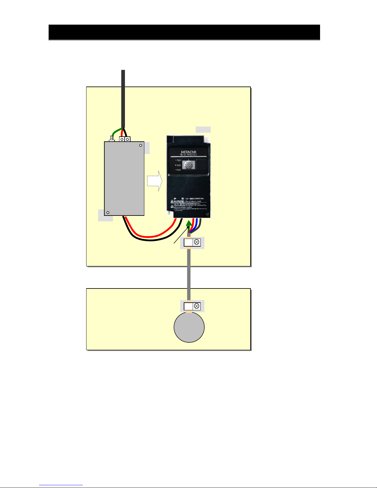
Installation for NE-S1 series (example of SB models)
Model LB (3-ph. 200V class) and HB(3-ph. 400V class) are the same concept for the installation.
*) Both earth portions of the shielded cable must be connected to the ea rth point by ca ble clamp s.
Input choke or equipment to reduce harmonic current is necessary for CE marking (IEC
61000-3-2 and IEC61000-3-4) from the harmonic current point of view, even conducted
emission and radiated emission passed without the input choke.
Shielded cable
Power supply
1-ph. 200V
M
U,V,W
Metal plate (earth)
Earth line is connected to the
heatsink of the inverter
(or PE terminal for bigger models)
PE
EMC filter
(Foot-print)
Cable clamp *
The filter is a footprint type, so it is located
between the inverter and the metal plate.
Remove the insulation material coating of the
earth contact portions so to obtain good
g
rounding condition.
Cable clamp *
Metal plate (earth)
L1,N

Chapter 1 Safety Instructions
1 - 9
Hitachi EMC Recommendations
WARNING
- This equipment should be installed, adjusted, and serviced by qualified personal familiar with
construction and operation of the equipment and the hazards involved. Failure to observe this
precaution could result in bodily injury.
Use the following checklist to ensure the inverter is within proper operating ranges and conditions.
1. The power supply to NE-S1 inverters must meet these specifications:
Voltage fluctuation ±10% or less
Voltage imbalance ±3% or less
Frequency variation ±4% or less
Voltage distortion THD = 10% or less
2. Installation measure:
Use a filter designed for NE-S1 inverter. Refer to the instruction of the applicable external
EMC filter.
3. Wiring:
Shielded wire (screened cable) is required for motor wiring, and the length must be 20
meter or less.
If the motor cable length exceeds the value shown above, use output choke to avoid
unexpected problem due to the leakage current from the motor cable.
The carrier frequency setting must be 2 kHz to satisfy EMC requirements.
Separate the power input and motor wiring from the signal/process circuit wiring.
4. Environmental conditions—when using a filter, follow these guidelines:
Ambient temperature: –10 to 50 °C
(Derating is required when the ambient temperature exceeds 40 °C)
Humidity: 20 to 90% RH (non-condensing)
Vibration: 5.9 m/sec2 (0.6 G) 10 ~ 55Hz
Location: 1000 meters or less altitude, indoors (no corrosive gas or dust)
!

Chapter 1 Safety Instructions
1 - 10
1.3 Precautions Concerning Compliance with UL and cUL Standards
(Standard to comply with : UL508C,CSA C22.2 No.14 -05 )
a) Maximum surrounding air temperature rating of 50ºC.
b) Solid St ate motor overload protection reacts with max. 150 % of FLA.
c) Suitable for use on a circuit capable of delivering not more than 100,000 rms Symmetrical Amperes,
240 Volts Maximum. For models 200V class.
Suitable for use on a circuit capable of delivering not more than 100,000 rm s Symmetrical Amperes,
480 Volts Maximum.For models 400V class.
d) Drive has no provision for motor over temperature protection.
e) When protected by J, CC, G or T Class Fuses. or When protected by a circuit breaker having an
interrupting rating not less than 100,000 rms symmetrical amperes, 240 Volts maximum. For models
200V class.
When Protected by J, CC, G or T Class Fuses. For model s 400V class.
f) Integral solid state short circuit protection does not provide branch circuit protection. Branch circuit
protection must be provided in accordance with the National Electrical Code and any additional local
codes.
g) Install device in pollution degree 2 environment
h) Branch circuit short circuit protection can use fuse or circuit breaker only. For models 200V class..
Branch circuit short circuit protection can use fuse only. For models 400V class..
i) Use 60/75ºC CU wire only.
j) Tightening torque and wire range as sho wn in the table below.
Model No. Required Torque (N.m) Wire Range(AWG)
NES1-002S,004S 0.8~1.0 16~14
NES1-007S 1.8 14~12
NES1-015S 1.8 12~10
NES1-022S 1.8 10
NES1-002L,004L,007L 0.8~1.0 16~14
NES1-015L 1.8 14
NES1-022L 1.8 12
NES1-004H,007H,015H 1.8 16
NES1-022H,040H 1.8 14
j) Distribution fuse and circuit breaker size marking is included in the manual to indicate that the unit
shall be connected with a Listed Cartridge Nonrenewable fuse or Inverse time circuit breaker, rated
600 VAC with the current ratings as shown in the table below:
* In case of using Circuit Breaker, an additional 5 A external protector is needed.
Model No.
Fuse Circuit Breaker
Type Maximum Ratin
g
Type Maximum Ratin
g
NES1-002S,004S
Class J, CC, G or T
10 A
Inverse
Time
15 A
NES1-007S 20 A
NES1-015S,022S 30 A 30 A
NES1-002L*,004L*
Class J, CC, G or T
10 A
Inverse
Time
15 A
NES1-004L*
NES1-007L*,015L 15 A
NES1-022L 20 A 20 A
NES1-004H,007H,
015H,022H,040H
Class J, CC, G or T 15A - -
PD
R
S
T
U
V
W
P
Inverter
Power
supply
Motor
DC link choke
Circuit breaker or
Fuse
Wiring diagram of inverter

Chapter 2 Inspection of the Purchased Product
This chapter describes the inspection of the purchased product, the product
warranty.
2.1 Inspection of the Purchased Product ·············2 - 1
2.2 Method of Inquiry and Product Warranty ········2 - 2


Chapter 2 Inspection of the Purchased Product
2 - 1
2.1 Inspection of the Purchased Product
(A) Inspecting the product
Please check the followings after unpacking.
Please contact your supplier or local Hitachi Distributor
if there are any problems like below on the product.
(1) Any damage duri ng transportation?
(2) Basic manual (English and Japanese) are packed
together with the product?
(3) The product is the one you ordered.
(check with the specification label)
“*” Restricted Distribution
C : China
E : Europe
None : Other (Standard)
-002SB*
200-240
200-240
3.1
1.4
2616200716000001
1206
-001
Example of the specification label
Model name
(NES1-002SB example)
Manufacturing number
Freq.
In
p
ut
Volta
g
e
Phase
Current
Freq.
Output
Volt. & phase
Current
Specification label
Production Management label

Chapter 2 Inspection of the Purchased Product
2 - 2
2.2 Method of Inquiry and Product Warranty
(A) Method of inquiry
In case of contacting to the store you bought the product or Hitachi, please inform the following
information.
(1) Model name of the inverter
(2) Manufacturing number (MFG No.)
(3) When you bought the product
(4) Contents of your inquiry
- Damaged portion and condition, and else.
(B) Product warranty
The product will be warranted for one year after the date of purchase.
Even within the warranty period, repair of a product fault will not be covered by the warranty (but the repair
will be at your own cost) if:
(1) the fault has resulted from incorrect usage not conforming to the instructions given in this
Instruction Manual or the repair or modification of the product carried out by an unqualified person,
(2) the fault has resulted from a cause not attributable to the delivered product,
(3) the fault has resulted from use beyond the limits of the product specifications, or
(4) the fault has resulted from disaster or other unavoidable events.
The warranty will only apply to the delivered inverter and excludes all damage to other equipment and
facilities induced by any fault of the inverter.
Repair at the user's charge
Following the one-year warranty period, any examination and repair of the product will be accepted at your
charge. Even during the warranty period, examination and repairs of faults, subject to the above scope of
the warranty disclaimer, will be available at charge.
To request a repair at your charge, contact your supplier or local Hitachi Distributor.
The Hitachi Distributors are listed on the back cover of this Instruction Manual.
(C) Warranty Terms
The warranty period under normal installation and handling conditions shall be two (2) years from the date
of manufacture (“DATE” on product nameplate), or one (1) year from the date of installation, whichever
occurs first. The warranty shall cover the repair or replacement, at Hitachi’s sole discretion, of ONLY the
inverter that was installed.
(1) Service in the following cases, even within the warranty period, shall be charged to the purchaser:
a. Malfunction or damage caused by mis-operation or modification or improper repair
b. Malfunction or damage caused by a drop after purchase and transportation
c. Malfunction or damage caused by fire, earthquake, flood, lightening, abnormal input voltage,
contamination, or other natural disasters
(2) When service is required for the product at your work site, all expenses associated with field repair
shall be charged to the purchaser .
(3) Always ke ep this QRG handy; please do not loose it. Please contact your Hitachi distributor to
purchase replacement or additional QRG.

Chapter 3 Exterior Views
This chapter describes the exterior views and the names of parts.
3.1 Exterior Views and Names of Parts ···············3 - 1
3.2 Name of each portion
(removing the front cover) ···························3 - 2

Chapter 3 Exterior Views
3 - 1
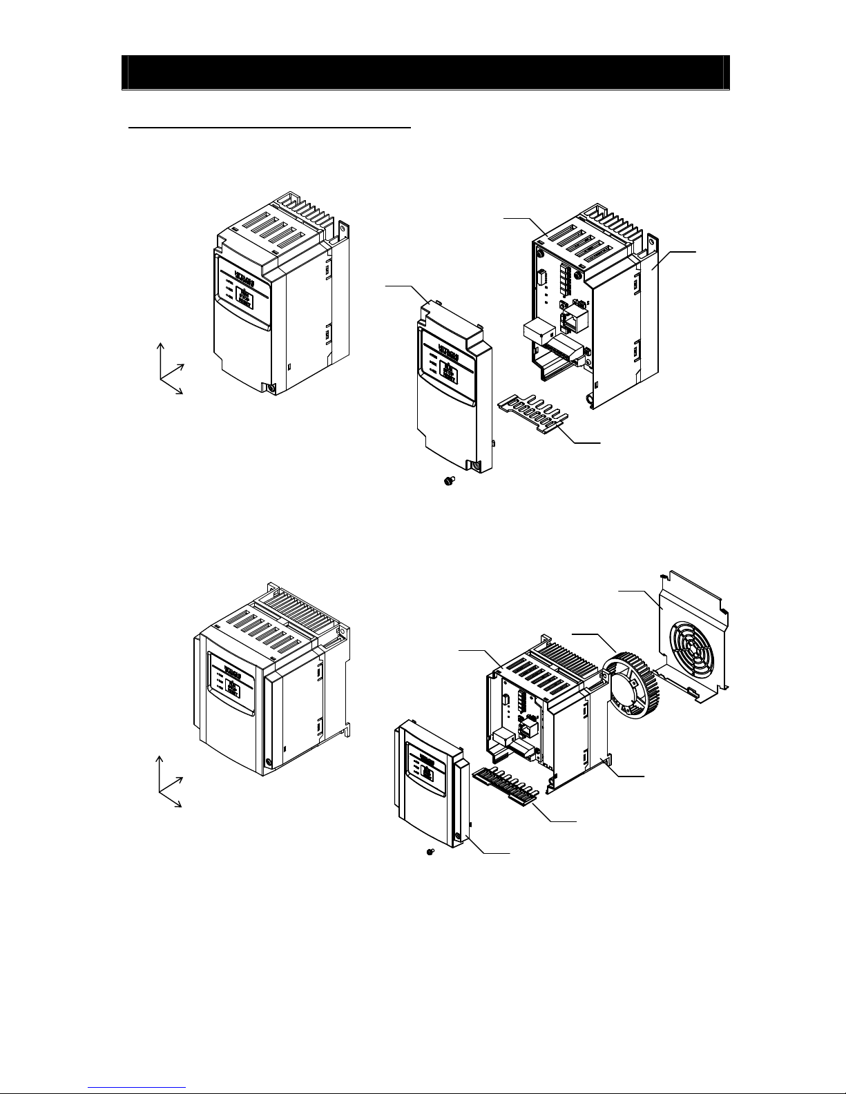
*)002-007SB/LB and 004HB : without Cooling Fan
3.1 Exterior Views and Names of Parts
The figure below shows an exterior view of the inverter
- model : NES1 – 002*,004*SB/LB , 007*LB
- model : NES1 – 007*SB , 015,022SB , 004*,007,015,022HB,040HB
a) Cooling Fan Cover d) Case
b) Cooling Fan e) Front Cover
c) Heat sink f) Backing plate
W
D
H
W
D
H
c
d
e
f
c
d
e
f
b
a
Chapter 3 Exterior Views
3 - 2
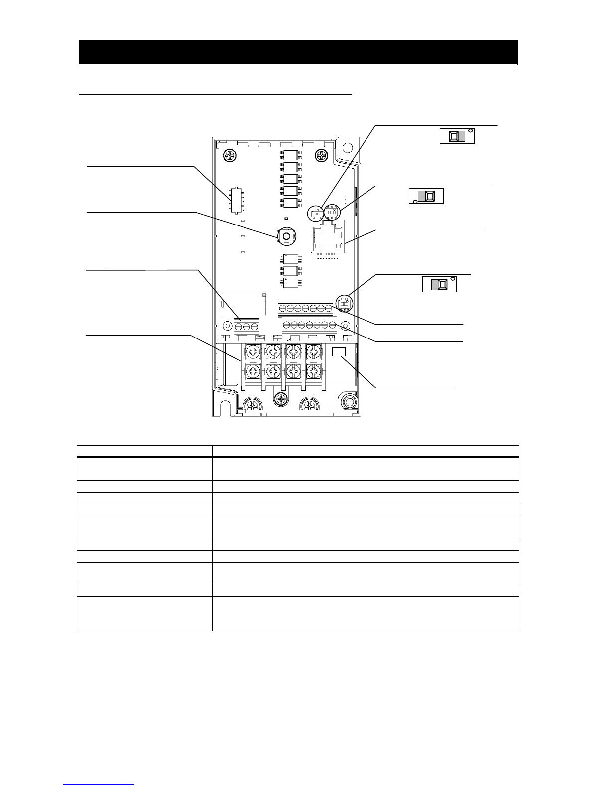
3.2 Name of each portion (removing the front cover) Note1)
Name Description
1) Connector of dedicated operator for
NES1-OP
Dedicated operator for NE-S1 (NES1-OP) can be connected.
2) RUN/STOP/RESET key Push key for run, stop and reset operation.
3) Intelligent relay terminal Output terminal for intelligent relay (1c contact).
4) Main terminal For connecting power supply, motor output and DC reactor.
5) Switch for termination resistor Changeover for integrated resistor (100Ω) for RS485.Integrated resistor of 100Ω is
connected when turning ON.
6) Switch for RS485/OPE Changeover switch for RS422/RS485.
7) RS422/RS485 port Connector for RS485 or external operator and PC software (RJ45 jack)
8) Switch for O/OI (analog input)
changeover
Voltage input (O) or current input (OI) can be selected.
9) Logic terminal A,B Terminal for connecting input/output signals (digital/analog) for the inverter control.
10) Charge lamp Turns ON when the internal DC bus voltage is 45V or more.
In case of wiring, maintenance or else, be sure to check that this lamp is turned OFF after
waiting 10 minutes of power OFF.
Note 1) Refer to section 6.5 How To Operate the Inverter.
Note 2) Position of “10) charge lamp” depends on the model. Refer to page 2-11 for the details.
Note 3) Pay attention when operating by PC via “7)RS422/RS485 port”, because the operation can also be done from the
panel of the inverter.
Note 4) Be sure to turn power OFF when connecting or disconnecting the operator such as OPE-SRmini,OPE-S,WOP to the
“7) RS422/RS485 port”.
Note 5) When communication becomes unstable, Please do not use the termination resistor of the inverter. Please use a
termination resistor suitable for your environment.
6) Switch for RS485/OPE SW5
5) Switch for termination resistor SW4 Note5)
7) RS422/RS485 port Note3) Note4)
2) RUN/STOP/RESET key
4) Main terminal
9) Logic terminal A
section 5.4
8) Switch for O/OI (analog input)
changeover SW6
9) Logic terminal B
3) Intelligent relay terminal
10) Charge lamp Note2)
1) Connector of dedicated
operator for NES1-OP
section 5.4
OFF
(Default)
ON
section 5.4, 8.3
RS485
OPE
(Default)
→section 5.4, 8.3
Voltage O
(Default)
Current OI
section 5.4
section 5.5

Chapter 3 Exterior Views
3 - 3

Chapter 4 Installation
This chapter describes how to install the inverter.
4.1 Precautions for installation ··························4 - 1


Chapter 4 Installation
4 - 1
4.1 Precautions for installation
CAUTION
- Install the inverter on a non-flammable surface, e.g., metal. Otherwise, you run the risk of fire.
- Do not place flammable materials near the installed inverter . Otherwise, you run the risk of fire.
- When carrying the inverter, do not hold its top cover. Otherwise, you run the risk of injury by dropping
the inverter.
- Prevent foreign matter (e.g., cut pieces of wire, sputtering welding materials, iron chips, wire, and
dust) from entering the inverter. Otherwise, you run the risk of fire.
- Install the inverter on a structure able to bear the weight specified in the Instruction Manual.
Otherwise, you run the risk of injury due to the inverter falling.
- Install the inverter on a vertical wall that is free of vibrations. Otherwise, you run the risk of injury due
to the inverter falling.
- Do not install and operate the inverter if it is damaged or its parts are missi ng. Otherwise, you run the
risk of injury.
- Install the inverter in a well-ventilated indoor site not exposed to direct sunlight. Avoid places where
the inverter is exposed to high temperature, high humidity, condensation, dust, explosive gases,
corrosive gases, flammable gases, grinding fluid mist, or salt water. Otherwise, you run the risk of fire.
- The inverter is precision equipment. Do not allow it to fall or be subject to high impacts, step on it, or
place a heavy load on it. Doing so may cause the inverter to fail.
- When you touch the inverter, you must take care at static electricity. Doing so may cause the inverter
to fail.
!

Chapter 4 Installation
4 - 2
(1)Caution during transportation
Please pay attention when carrying the product because it is covered by plastic case.
Especially, do not put pressure onto the front cover and terminal cover . Otherwise there i s a ri sk of falling
down the product. Please do not use products having damage, and/or lacking components.
(2)Ensure Adequate Ventilation
To summarize the caution messages – you will need to find a solid, non-flammable, vertical surface that
is in a relatively clean and dry environment. In order to ensure enough room for air circulation around the
inverter to aid in cooling, it is recommended to maintain the specified clearance and the inverter
specified in the below diagram.
(3)Caution for ambient temperature
Set ambient temperature at installation site within the standard specification range (-10~50C).
Measure ambient temperature at the place apart by 5cm from the bottom center of inverter main body
and confirm that it is within the allowable temperature range.
Using the inverter at higher temperature than allowable temperature may result in shortening of
lifetime of inverter (especially of electrolytic capacitor). Derating curve is shown on section 12.3.
(4)Do not install the inverter in such places as high temperature, high humidity, or easy to condensate.
Use the inverter within the allowable humidity range (20~90%RH) described in standard
specifications.
Especially , please use it in place where no dew condensation o ccurs. If dew condensation occurs and
beading is generated inside the inverter, electronic parts are short-circuited each other to cause a
failure. Also, please avoid i nstalling it in a location which receives direct sunlight.
(5)Caution for installation environment
Please avoid installing the inverter in such places where dust, corrosive gas, explosive gas,
flammable gas, mist of grinding fluid, or salt pollution, etc. exists.
Invasion of dust, dirt etc. into the inverter may cause a failure. So, when you use it in dusty place by
necessity, please devise a countermeasure such as putting it into a closed type chassis.
Adequate space for the airflow
must be kept. Pay attention for
wiring duct installation.
5 cm (1.97”)
minimum
5 cm (1.97”)
minimum
10 cm (3.94”)
minimum
10 cm (3.94”)
minimum
- Do not open the front cover during live parts inside.
WARNING
- Reduction of the carrier frequency or using bigger kW model is required if depends on the load or ambient.
CAUTION
Surface
Airflow
Installation of the method of "Side-by-Side" does
not have UL standard to comply.

Chapter 4 Installation
4 - 3
(6)Cautions for installation direction
Surface of the installation must be no vibration, and should be capable of holdin g the weight of the
product. And the product must be fixed to the surface with a proper screws with vertical direction.
Be sure to screw using all the screw holes for the installation.
(002L/SB,004L/SB,007LB : 2 positions, 004HB,007S/HB,015L/S/HB,022L/S/HB : 4 positions)
There is a risk of performance failure, and/or breakdown when the product is not installed vertical
direction.
(7)Cautions for installation into the cabinet
Please pay attention to the location of the ventilation holes of the inverter and the cabinet, in case of
side-by-side installation and using ventilation fan.
cooling performance of the inverter highly depe nds on the location of the holes. Please pay high
attention to the ambient temperature of the inverter to be less than the specified value.
(8)Watt Loss
1-ph./3-ph. 200V class
Model name 002S/L 004S/L 007S/L 015S/L 022S/L
Watt Loss (100% load)(W) 22 30 48 79 104
Efficiency at rated load(%) 90 93 94 95 95.5
3-ph. 400V class
Model name 004H 007H 015H 022H 040H
Watt Loss (100% load)(W) 35 56 96 116 167
Efficiency at rated load(%) 92 93 94 95 96
Ventilation
Position of the ventilation
(
Good
)
Ventilation
Inverte
r
(
Bad
)
Inverte
r

Chapter 5 Wiring
This chapter describes the wiring of main circuit and control signal terminals.
5.1 Precautions for Wiring ······························5 - 1
5.2 How to attach and remove the front cover ·······5 - 2
5.3 How to attach the Exclusive operator
(NES1-OP) ··············································5 - 3
5.4 Wiring and terminal description ····················5 - 4
5.5 Mains wiring ·············································5 - 7
5.6 Wiring of the control circuit ··························5 - 12
5.7 Connection with the programmable
controller (PLC) ········································5 - 14
5.8 Notes on using multiple inverters ··················5 - 15


Chapter 5 Wiring
5 - 1
5.1 Precautions for Wiring
WARNING
- In order to prevent damage caused by static electricity, Please remove the static electricity of the body
touch the nearby metal before touching this product.
- Be sure to ground the inverter. Otherwise, you run the risk of electric shock or fire.
- Commit wiring work to a qualified electrician. Otherwise, you run the risk of electric shock or fire.
- Before wiring, make sure that the power supply is off. Otherwise, you run the risk of electric shock or
fire.
- Perform wiring only after installing the inverter. Otherwise, you run the risk of electric shock or injury.
- The inverter must be powered OFF before you change any of the slide switch settings.Otherwise, you
run the risk of electric shock or injury.
CAUTION
- Make sure that the voltage of AC power supply matches the rated voltage of your inverter.
Otherwise, you run the risk of injury or fire.
- Do not input single-phase power into the 3-phase inverter. Otherwise, you run the risk of fire.
- Do not connect AC power supply to any of the output terminals (U, V, and W). Otherwise, you run the
risk of injury or fire.
- NE-S1 series inverter do not have terminals for braking resistor. Do not connect the resistor.
Otherwise there is a risk of fire.
- Connect an earth-leakage breaker to the power input circuit. Otherwise, you run the risk of fire.
- Use only the power cables, earth-leakage breaker, and magnetic contactors that have the specified
capacity (ratings). Otherwise, you run the risk of fire.
- Do not use the magnetic contactor installed on the primary and secondary sides of the inverter to
stop its operation.
- Tighten each screw to the specified torque. No screws must be left loose. Otherwise, you run the risk
of fire.
- Before operating slide switch in the inverter, be sure to turn off the power supply. Otherwise, you run
the risk of electric shock and injury.
- Please make sure that earth screw was tighten completely in advance.
- First, check the tightening the screws of output terminal (U, V and W), and then tighten the screws
of input terminal (R,S and T).
- Factory default of C036 is "b contact(NC)". In the event that the initialization, C036 will be the “b
contact(NC)”. If you wish to use as a replacement for the conventional model of this inverter, such as
in the case of built-in system use, please first check the configuration of C036. And, you must
conform to the peripheral circuit logic. There is a risk of system down by logical inconsistency
contact.
!
!

Chapter 5 Wiring
5 - 2
5.2 How to attach and remove the front cover
(1) How to remove
(2) It is necessary to make window on the front cover when using remote operator
(OPE-S/SR/SBK/SRmini, WOP), Modbus-RTU, or PC software (ProDriveNext). See above for the
position of the window.
- Be sure to make window after removing the front cover.
- There are cutouts at the window, so it can be removed easily by pressing up side and bottom side of
the window alternatively.
- The window cannot be restored if it is once opened. Please use commercially supplied RJ45
connector cap or the like if necessary.
(3) How to attach
- Press the front cover to the main body until there is a click sound.
- Do not tighten the screw too much.
1) Loosen up the screw
2) remove the cover by pressing the bottom side o
f
the cover to the direction shown below.
3) Move the wiring plate like shown below
in case of wiring.
Screw for fixing the front cover is located at right-bottom side
Screw for fixing
front cove
r
Front cover
Window for connecting
RS422/RS485
Screw for fixing
front cove
r
Press in this direction

Chapter 5 Wiring
5 - 3
5.3 How to attach the Exclusive operator (NES1-OP)
Note) Please set SW4, SW5 on the board, before installation of exclusive operator (NES1-OP).
5) Figure of installation (NES1-OP)
1) Remove the front cover from main body
2) Cut the standard operator panel by in thin–blade-nipper and
take it off.
3) The connector of the exclusive operator (NES1-OP)
connect to the connector on the circuit board. And attach it
to put the circuit board.
4) Attach the front cover.
Cut (6 points)

Chapter 5 Wiring
5 - 4
5.4 Wiring and terminal description
Note 1) Above shows an example of voltage (O) input. Changeover of SW6 must be done in case of current (OI) input.
Single phase
Intelligent inputs,
7 terminals
0-10VDC(10bit)
PLC
P24
DC24V
L
P/+
H
O/OI
Category D grounding (200V class)
Category C grounding (400V class)
DC10V
5
2
1
3
4
Intelligent input terminal
11
CM2
Relay contacts
AL0
AL1
AL2
L
DC10V
(10mA Max.)
4.7kΩ
4.7kΩ
L
FM
L
Pulse train output
L
L
PD/+1
Refer to P5-13 when using external
equipment for source logic output
and/or external power supply.
Short circuit bar
Short circuit bar
DCL
Remove the jumper
wire when using DCL
(DC link choke)
ELB
1kΩ~2kΩ
(L1)
(N)
A
pprox.
250Ω
O
OI
SW6
Motor
U/T1
V/T2
W/T3
M
Power source,
3-phase or
1-phase, per
inverter model
R/L1
S/L2
T/L3
MC
A
pprox.1
0kΩ
(Shipment setting of "E" Version is
source logic output connection.)

Chapter 5 Wiring
5 - 5
(1) Mains terminal description
Symbol Name Description
R/L1(L1)
Power input
terminals
Connect power supply
- Use [L1] and [N] terminal in case of 1-ph. 200V power supply
S/L2
T/L3(N)
U/T1
Power output
terminals
Connect 3-ph. motor
V/T2
W/T3
PD/+1
DC link choke
connection
terminal
First, remove the short circuit bar between PD/+1 and P/+ terminal.
Then connect optional DC link choke for improving the input
harmonics.
P/+
G( )
Earth terminal
To make grounding. Be sure to make this grounding to avoid
electric shock, and for improving the EMC performance. The
terminal is located on the heatsink.
(2) Control terminal description
Categor
y
Symbol Name Description Electrical characteristics
Power
supply
L
Common for input
signals
Common for internal control
power supply, digital
inputs/outputs, analog
inputs/outputs
H
Power supply for
freq.se
t
DC10V power supply. Used with
variable resistor for O input.
Max.10mA withdraw
Analog
Freq.
set
O/OI
Analog voltage
(Use SW6 for
changeover)
Frequency set via DC0~10V input
Input
impedance=apprx.10kΩ
Allowable range;
-0.3~+12VDC
Analog current
(Use SW6 for
changeover)
Frequency set via 0~20mA
Parameter adjustment should be
done in case of 4~20mA
Input
impedance=apprx.250Ω
Allowable range;
0~20m
A
Digital
Power
supply
L
Common for dig.
Inputs
Common for internal control
power supply, digital inputs,
analog inputs/outputs
(Sink terminal)
P24
Power supply for
dig. inputs
DC24V power supply for dry
contact input. (Common terminal
in case of source logic) note)
Max.100mA output
PLC
Power supply
terminal
for input terminals
Sink logic : connected to P24
Source logic : connected to L
Remove the jumper wire when
using external power supply for
controlling the dry contact inputs.
23
24
25
26
27
28
29
0 20406080100
note )The voltage of P24 changes like the chart below by a load electric current. In the case of use, please be
careful about external equipment. (ext-operator:OPE-S/SR/SBK/SRmini)
As for this chart application, it is just for December, 2012 production.
Thereafter, all models become the curve to show in 015,022L/SB.
P24
[
Vdc
]
P24 - load electric current properties
load electric current [mA]
002~007L/SB (without ext-operator)
002~007L/SB (with ext-operator)
015, 022L/SB (without ext-operator)
015, 022L/SB (with ext-operator)

Chapter 5 Wiring
5 - 6
(3) Changeover switch description
Refer to section 3.2 for the location of the switches.
Category Symbol Name Description Electrical characteristics
Digital
Input
Contact
5
4
3
2
1
Intelligent
input
terminals
5 functions from 35
functions can be assigned
to terminal 1 to 5. Sink or
source logic can be
selected.
Voltage between each input and PLC
- V(ON) = min.18V
- V(OFF) = MAX.3V
- Max. allowable voltage = 27VDC
- Load current 5mA (24V)
Output
Open-collector
11
Intelligent
output
terminals
One function from 28
functions can be assigned.
Open collector output
Between 11 and CM2
- Voltage drop during ON=4V or less
- Max. allowable voltage = 27V
- Max allowable current = 50mA
CM2
Common for
intelligent
output
terminals
Common for the terminal
11.
Max. allowable current = 100mA
Relay
AL0
AL1
AL2
Intelligent relay
outputs
One function from 28
functions can be assigned.
(1-c contact)
Max. contact capacity
AL1-AL0 : AC250V,
2A(resistive),0.2A(inductive)
AL2-AL0 : AC250V,
1A(resistive),0.2A(inductive)
Min. contact capacity
AC100V, 10mA
DC5V, 100mA
Pulse
train
FM
Digital pulse
train output
Pulse frequency
MAX.3.6kHz
Pulse voltage : DC0/10V output
Max. allowable current : 2mA
Symbol Name Description
SW4
Termination resistor
changeover switch
Select able/disable of the termination resistor of RS485 port (RJ45)
OFF
(left side)
Termination resistor (100Ω) Disable (Default)
ON
(right side)
Termination resistor (100Ω) Able
SW5
RS485/OPE(RS422)
changeover switch
Select depending on the options and communication method, connected
to RS422/RS485 port.
OFF
(right side)
For operator (OPE-S/SR/SBK/SRmini),ProDriveNext
(Default)
ON
(left side)
For RS485 communication (Modbus-RTU)
SW6
A
nalog input (O/OI)
changeover switch
OFF
(left side)
Current input (0~20mA) OI
ON
(right side)
Voltage input (0~10Vdc) O (Default)
- Adjustment of the switch must be done during power off. Otherwise there is a risk of electric shock.
- Power ON must be done after closing the front cover. Do not open the front cover during power up, or when
there is a remaining voltage. There is a risk of electric shock.
CAUTION

Chapter 5 Wiring
5 - 7
5.5 Mains wiring
(1) Cautions on wiring
Be sure to confirm that the charge lamp is turned OFF before the wiring work.
Once it is powered up, there will be a remaining voltage at the DC bus capacitor for a certain period
regardless the motor operation.
Wiring work must be done 10 minutes after the power off, after confirming the safety.
In case the power indication of the operator does not turn ON after power-up, inverter may be damaged.
In that case, the inspection must be done after waiting 2 hours or more of the power OFF. Otherwise there
is a danger of electric shock and/or injury.
1)Mains input terminals (R/L1,S,T/N)
・ Use earth leakage breaker (ELB) for protection between power supply and input terminals
(R/L1,S,T/N).
・ The ELB is recommended to have bigger capability for the high frequency sensitivity, so to avoid
malfunction.
Distance
between
inverter and
motor
Cutoff
current of
ELB
100m or less 30mA
300m or less 100mA
800m or less 200mA
・ There is a possibility that the malfunction or failure of the customer’s system when the protection
circuit of the inverter is activated. Please use magnet contactor to shutoff the inverter power supply.
・ Do not turn power ON and OFF by the magnet contactor at the primary side or secondary side of the
inverter to start and stop the motor. Use operation command (FW, RV) from the control input terminal
in case of using external signal.
・ Do not use the 3-ph input type with single phase input (phase loss). Otherwise there is a risk of
inverter failure. Single phase input to the 3 phase type inverter will result in a undervoltage,
overcurrent, or will result in a damage of the inverter. [DC bus capacitor will be charged even under
phase loss and it is dangerous. Refer to “(1) Cautions for wiring” for the wiring.]
・ There is a risk of breakdown of the internal converter module, and/or shortening drastically the lifetime
of DC bus capacitors due to an increase of the ripple current. Especially, if high reliability is required
on the system, use AC reactor between power supply and inverter. And if a thunder is expected, use
appropriate lightening protection equipment.
- Unbalance at the input voltage (3% or more)
- Impedance of the power supply is 10 times or more, and 500kVA or more
- Rapid change is voltage is expected
(Example) - 2 or more inverters are connected at the same net with short cable.
- Inverter is connected in parallel with the thyristor equipment with short cable.
- Phase advancing capacitor is switching on a same net
・ Frequency of the power ON/OFF must be once/3 minites or longer interval. There is a danger of
inverter failure.
・ An inverter run by a private power generator may overheat the generator or suffer from a deformed
output voltage waveform of the generator. Generally, the generator capacity should be five times that
of the inverter (kVA) in a PWM control system or six times greater in a PAM control system.
・ In the case of important equipment, to shorten the non-operational time of inverter failure, please
provide a backup circuit by commercial power supply or spare inverter.
[Rough indication of earth leakage current] 30mA/km : use CV
cable with metallic tube. Leakage current will be approximately 8
times more when using H-IV cable.
Therefore, it is recommended to use one class bigger capability of
the ELB. Previously mentioned “leakage current” is based on the
RMS value of fundamental wave, excluding harmonic current.

Chapter 5 Wiring
5 - 8
・ In case of commercial power source switching functions,mechanical interlock the MC1 & MC2
contacts with each others is required.Otherwise you may damage the inverter and the danger of injury
and/or fire.Please refer to following diagram.
2)Inverter output terminals (U(T1), V(T2), and W(T3))
・ Use a cable thicker than the specified applicable cable for the wiring of output terminals to prevent the
output voltage between the inverter and motor dropping. Especially at low frequency output, a voltage
drop due to cable will cause the motor torque to decrease.
・ Do not connect a phase-advanced capacitor or surge absorber on the output side of the inverter. If
connected, the inverter may trip or the phase-advanced capacitor or surge absorber may be
damaged.
・ If the cable length between the inverter and motor exceeds 20 m (especially in the case of 400 V
class models), the stray capacitance and inductance of the cable may cause a surge voltage at motor
terminals, resulting in a motor burnout. A special filter to suppress the surge voltage is available. If
you need this filter, contact your supplier or local Hitachi Distributor.
・ When connecting multiple motors to the inverter, connect a thermal relay to the inverter output circuit
for each motor.
・ The RC rating of the thermal relay must be 1.1 times as high as the rated current of the motor. The
thermal relay may go off too early, depending on the cable length. If this occurs, connect an AC
reactor to the output of the inverter.
3)DC reactor connection terminals (PD(+1) and P(+))
・ Use these terminals to connect the optional DC power factor reactor (DCL).
As the factory setting, terminals P(+) and PD(+1) are connected by a jumper.
Remove this to connect the DCL.
・ The cable length between the inverter and DCL must be 5 m or less.
Remove the jumper only when connecting the DCL.
If the jumper is removed and the DCL is not connected, power is not supplied to the main circuit of
the inverter, and the inverter cannot operate.
4)Inverter ground terminal (G )
・ Be sure to ground the inverter and motor to prevent electric shock.
・ According to the Electric Apparatus Engineering Regulations, connect 200 V class models to
grounding electrodes constructed in compliance with type-D grounding (conventional type-III
grounding with ground resistance of 100Ω or less) or the 400 V class models to grounding electrodes
constructed in compliance with type-C grounding (conventional special type-III grounding with ground
resistance of 10Ω or less).
・ Use a grounding cable thicker than the specified applicable cable, and make the ground wiring as
short as possible.
・ When grounding multiple inverters, avoid a multi-drop connection of the grounding route and
formation of a ground loop, otherwise the inverter may malfunction.
Power
source
R/L1 U
S Inveter V
T/N W
Motor
ELB
MC0
MC1
MC2
Inverter
Inverter
Inverter
Grounding bolt
prepared by user
Inverter
Inverter
Inverter

Chapter 5 Wiring
5 - 9
(2) Layout of main circuit terminals
The figures below show the terminal layout on the main circuit terminal block of the inverter.
The main circuit terminal block opens a faceplate and wires it.
Single-phase 200V 0.2 to 0.4kW
Three-phase 200V 0.2 to 0.75kW
Single-phase 200V 0.75 to 2.2kW
Three-phase 200V 1.5 , 2.2kW
Three-phase 400V 0.4 to 4.0kW
Single-phase
type
Three-phase
type
From source
To motor
L1 N P/+
PD/+1
W/T3V/T2U/T1
R/L1 T/L3 P/+
PD/+1
W/T3V/T2
U/T1
S/L2
Charge lump
Three-phase type
Single-phase type
L1
N
PD/+1 P/+
U/T1
W/T3V/T2
R/L1 T/L3S/L2
W/T3
V/T2 U/T1
PD/+1
P/+
From source
To motor
Charge lump
Ground terminal
Charge
lamp
Ground terminal
Charge
lamp

Chapter 5 Wiring
5 - 10
(3) Applicable peripheral equipment
Note 1: The peripheral equipment described here is applicable when the inverter
connects a standard Hitachi 3-phase, 4-pole squirrel-cage motor.
Note 2: Select breakers that have proper capacity.
(Use breakers that comply with inverters.)
Note 3: Use earth-leakage breakers (ELB) to ensure safety.
Note 4: Use copper electric wire (HIV cable) of which the maximum allowable
temperature of the insulation is 75°C.
Note 5: If the power line exceeds 20 m, cable that is thicker than the specified
applicable cable must be used for the power line.
Note 6: Use a 0.75 mm
2
cable to connect the alarm output contact.
Note 7: Tighten each terminal screw with the specified tightening torque.
Loose terminal screws may cause short circuits and fire.
Tightening a terminal screw with excessive torque may cause damage to the
terminal block or inverter body.
Note 8: Select an earth-leakage breaker (ELB) of which the rated sensitivity current
matches the total length of cables connected between the inverter and power
supply and between the inverter and motor. Do not use a high-speed type ELB
but use a delayed-type ELB because the high-speed type may malfunction.
Note 9: When a CV cable is used for wiring through a metal conduit, the average
current leakage is 30 mA/km.
Note 10: When an IV cable, which has a high relative dielectric constant, is used, the
leakage current is about eight times as high as the standard cable. Therefore,
when using an IV cable, use the ELB of which the rated sensitivity current is
eight times as high as that given in the table below. If the total cable length
exceeds 100 m, use a CV cable.
Note11: If there are any thyristor equipments belonging to the same net, and a
possibillty that the surge voltage is given to the net, change the connecting
order of above a) and b). (Connecting order: Net→ELB→Contactor
→Noise filter b)→Input Choke a)→Inverter).
Otherwise, there is a danger of damaging inverter and/or fire.
Name Description
a) Reactor on input side (for
harmonic control, power
supply coordination, and
power factor improvement)
(
ALI-XXX) Note11
Use this reactor to control harmonic waves or when the
imbalance of power supply voltage is 3% or more, when the
power supply capacity is 500 kVA or more, or when the power
voltage may change rapidly. This reactor also improves the
power factor.
b) Noise filter for inverter
(NF-XXX) Note11
This noise filter reduces the conductive noise that is generated
by the inverter and transmitted in cables. Connect this noise
filter to the
p
rimary side (input side) of the inverter.
c) Radio noise filte
r
(Zero-phase reactor)
(
ZCL-X)
The inverter may generate radio noise through power supply
wiring during operation. Use this noise filter to reduce the radio
noise (radiant noise).
d) Radio noise filter on input
side
(Cap
acitor filter) (CFI-X
)
Use this noise filter to reduce the radiant noise radiated from
input cables.
e) DC reactor (DCL-X-XX)
Use this reactor to control the harmonic waves generated by
the inverter.
f) Noise filter on the output
side
(ACF-CX)
Connect this noise filter between the inverter and motor to
reduce the radiant noise radiated from cables for the purpose
of reducing the electromagnetic interference with radio and
television reception and preventing malfunctions of measuring
equipment and sensors.
g) Radio noise filte
r
(Zero-phase reactor)
(
ZCL-XXX)
Use this noise filter to reduce the noise generated on the
output side of the inverter. (This noise filter can be used on
both the input and output sides.
)
h) AC reactor for the output
side
For reducing vibrations and
preventing thermal relay
malfunction
(ACL-X-XX)
Using the inverter to drive a general-purpose motor may cause
larger vibrations of the motor when compared with driving it
directly with the commercial power supply. Connect this AC
reactor between the inverter and motor to lessen the pulsation
of motor. Also, connect this AC reactor between the inverter
and motor, when the cable length between them is long (10 m
or more), to prevent thermal relay malfunction due to the
harmonic waves that are generated by the switching operation
on the inverter. Note that the thermal relay can be replaced
with a current sensor to avoid the malfunction.
h) LCR filter
This filter converts the inverter output into a sinusoidal
waveform.
Total cable length Sensitivity current (mA)
100 m or less 30
300 m or less 100
800 m or less 200
Motor
Power
supply
ELB
Magnetic
contactor
PD
e)
R S T
U V W
INVERTER
a)
b)
c)
d)
f)
g)
h)
P

Chapter 5 Wiring
5 - 11
(4)Wiring and Accessories
The table below lists the specifications of cables, crimp terminals, and terminal screw tightening torques
for reference.
Input
Voltage
Motor
Output
(kW)
Applicable
inverter
model
NES1-
Wiring Accessories Note1)
Gauge of
power line
cable (mm
2
)
Note3)
Note4)
Size of
terminal
screw
Terminal
width
(mm)
Tighte
ning
Torque
(N-m)
Earth-leakage
breaker (ELB)
Note2)
Note5)
Magnetic
contactor
(MC)
Note2)
Fuse
(UL-rated,
class J,600V)
Note6)
1-phase
200V
0.2 002SB*
AWG14
(2.0)
M3.5
(7.6)
1.0 EB-30E(5A) HS10 10A
0.4 004SB*
AWG14
(2.0)
M3.5
(7.6)
1.0 EB-30E(10A) HS10 10A
0.75 007SB*
AWG14
(2.0)
M4
(10)
1.4 EB-30E(15A) HS10 15A
1.5 015SB*
AWG10
(5.5)
M4
(10)
1.4 EB-30E(20A) HS20 20A
2.2 022SB*
AWG10
(5.5)
M4
(10)
1.4 EB-30E(20A) HS20 30A
3-phase
200V
0.2 002LB*
AWG16
(1.25)
M3.5
(7.6)
1.0 EB-30E(5A) HS10 10A
0.4 004LB*
AWG16
(1.25)
M3.5
(7.6)
1.0 EB-30E(10A) HS10 10A
0.75 007LB*
AWG16
(1.25)
M3.5
(7.6)
1.0 EB-30E(10A) HS10 15A
1.5 015LB*
AWG14
(2.0)
M4
(10)
1.4 EB-30E(15A) HS10 15A
2.2 022LB*
AWG14
(2.0)
M4
(10)
1.4 EB-30E (20A) HS20 20A
3-phase
400V
0.4 004HB*
AWG16
(1.25)
M4
(10)
1.4 EX-50C (5A)
HS10
10A
0.75 007HB*
AWG16
(1.25)
M4
(10)
1.4 EX-50C(10A)
HS10
10A
1.5 015HB*
AWG16
(1.25)
M4
(10)
1.4 EX-50C(10A)
HS10
10A
2.2 022HB*
AWG14
(2.0)
M4
(10)
1.4 EX-50C(15A)
HS10
15A
4.0 040HB*
AWG14
(2.0)
M4
(10)
1.4 EX-50C(15A)
HS10
15A
Note 1)The peripheral equipment described here is applicable when the inverter connects a standard Hitachi 3-phase,
4-pole squirrel-cage motor.
Note 2)Select breakers that have proper capacity. (Use breakers that comply with inverters.) Select above proper ELB
capacity following above table for the 1pc inverter.1pc inveter must be supplied by the above proper 1pc ELB.
Note 3)If the power line exceeds 20m, cable that is thicker than the specified applicable cable must be used for the
power line.
Note 4)Use copper electric wire (HIV cable) of which the maximum allowable temperature of the insulation is 75°C.
Note 5)Use earth-leakage breakers (ELB) to ensure safety.
Note 6)To comply UL, use either ELB/or FUSE which is specified by UL for the Power supply for the inverter.
(
Please refer to Chapter1 “1.3 Precautions Concerning Compliance with UL and cUL Standards”)
Note 7)The earthed line, please use things more than electric wire diameter to show to the power line.
Note8) "*" changes by
Restricted Distribution.

Chapter 5 Wiring
5 - 12
5.6 Wiring of the control circuit
(1) Wiring instructions
1) Terminals L and CM2 are common to I/O signals and isolated from each other.
Do not connect these common terminals to each other or ground them.
Do not ground these terminals via any external devices. (Check that the external devices connected
to these terminals are not grounded.)
2) Use a shielded, twisted-pair cable (recommended gauge: 0.14-0.75 mm
2
) for connection to control
circuit terminals, and connect the cable insulation to the corresponding common terminal.
3) The length of cables connected to control circuit terminals must be 20m or less.
4) Separate the control circuit wiring from the main circuit wiring (power line) and relay control circuit
wiring. If these wirings intersect with each other unavoidably, square them with each other.
Otherwise, the inverter may malfunction.
5) When connecting a contact to a control circuit terminal (e.g., an intelligent input terminal), use a relay
contact (e.g., crossbar twin contact) in which even a very low current or voltage will not trigger any
contact fault.
6) When connecting a relay to an intelligent output terminal, also connect a surge-absorbing diode in
parallel with the relay.
7) Do not connect analog power supply terminals H and L or interface power supply terminals P24 and
L to each other. Otherwise, the inverter may fail.
8) Control circuit terminal block has two columns up and down. Lower terminal may wire difficult to
upper terminal wire to the first.
Therefore, please first wiring to lower terminal.
9) After wiring, gently pull the wire, please make lead wire have securely connected.
10) Make sure the wires are not shorted each other.
(2) Layout of control circuit terminals
terminal Screw diameter Tightening torque
Control circuit
terminal A,B
M2 0.2N・m
Relay terminal
M2
0.2N・m
Relay terminal
AL2 AL1 AL0
Relayoutput
Pulse
Output
Digital Input
Digital
Output
Short circuit bar
Analog Input
&10Vdc
CM2 11 2 1
4 3 5
P24 L PLC
L FM H
O/OI
Common&24Vdc
Control circuit terminal A
Control circuit terminal B
(sink logic)

Chapter 5 Wiring
5 - 13
[example] (sink logic)
Note1)The above is a method to perform analog input(O/OI) by voltage input. It is necessary for SW6
on the board to be set for voltage input(default).
Note2) If you want to connect a relay to an intelligent output terminal, please connect a surge
absorbing diode in parallel with the relay. The output circuit may malfunction by voltage surge.
(3) Switching the input control logic
- In the factory setting, and intelligent input terminals is the sink logic.
To switch the input control logic to the source logic, remove the jumper connecting terminals P24 and
PLC on the control circuit block, and then connect terminals PLC and L with the jumper.
1)Sink logic 2)Souce logic
Short circuit bar
PLC P24 L FM
CM2 11 1 2
Short circuit bar
PLC P24 L
FM
CM2 11 1
2
H O/OI L FM
L PLC P24
Frequency meter
Varia ble
Resistor
(1k~2k)
Short circuit bar
(sink logic)
5 4 3 2 1 CM2 11
(27Vdc 50mA max.)
RY
Note2)

Chapter 5 Wiring
5 - 14
5.7 Connection with the programmable controller (PLC)
(1) Connecting a programmable controller to intelligent input terminals
When using the internal interface power supply
When using an external power supply
(Remove the short circuit bar from the control circuit terminal
block.)
Sink logic
Source logic
(2) Connecting a programmable controller to intelligent output terminals
Sink logic
Source logic
PLC
Inverter
P24
DC24V
L
1
DC24V
S
COM
Output module
(EH-YTP**,etc.)
5
Inverter
Output module
(EH-YTP**,etc.)
DC24V
DC24V
COM
P24
PLC
L
1
5
CM2
11
COM
Inverter
Input module
(EH-XD**,etc.)
DC24V
Inverter
11
Input module
(EH-XD**,etc.)
CM2
COM
DC24V
DC24V
Inverter
Output module
(EH-YT**,etc.)
Short
circuit
bar
S
COM
P24
PLC
L
1
5
DC24V
Inverter
Output module
(EH-YT**,etc.)
S
COM
P24
PLC
L
1
5
Short
circuit
bar

Chapter 5 Wiring
5 - 15
5.8 Notes on using multiple inverters
A plurality of inverter uses the common input and when inverter is timing of different power-on, as shown in
the figure below the current flowing around. The input may be recognized as ON in spite of OFF.
In this
case, please put a diode(rated 50V/0.1A) as shown in the figure to prevent.
(1) Sink logic
The input is recognized
as ON in spite of OFF without Diode.
Providing a diode instead of the short circuit
bar, so that the current flowing is prevented.
Additional diode
P24
PLC
L
1
short circuit bar
P24
PLC
L
1
SW OFF
Power-ON
Power-OFF
Input
ON
P24
PLC
L
1
P24
PLC
L
1
Power-OFF
Input
OFF
short
circuit bar
SW OFF
Power-ON

Chapter 5 Wiring
5 - 16
(2)
Souce logic
P24
PLC
L
1
P24
PLC
L
1
SW OFF
Power-ON
Power-OFF
Input
ON
P24
PLC
L
1
P24
PLC
L
1
SW OFF
Power-OFF
short circuit bar
short
circuit bar
Power-ON
Input
OFF
The input is recognized
as ON in spite of OFF without Diode.
Providing a diode instead of the short circuit
bar, so that the current flowing is prevented.
Additional diode

Chapter 6 Operation
This chapter describes typical methods of operating the inverter, how to operate
the digital operator.
6.1 Precautions of Operation ····························6 - 1
6.2 Confirmation before power up the inverter ······6 - 2
6.3 Changing parameters ·································6 - 2
6.4 Power up the inverter ·································6 - 3
6.5 How To Operate the Digtal Operator ··············6 - 4
6.6 Motor Operation ········································6 - 11
6.7 Conduct a test run of the motor ····················6 - 17
6.8 When tripping occurs ·································6 - 19


Chapter 6 Operation
6 - 1
6.1 Precautions of Operation
WARNING
- Please do not rotate suddenly. Check the direction of rotation at low frequencies. Otherwise, there is a
danger of injury.
- While power is supplied to the inverter, do not touch any terminal or internal part of the inverter, check
signals, or connect or disconnect any wire or connector. Otherwise, you run the risk of electric shock
or fire.
- Be sure to close the top cover before turning on the inverter power. Do not open the top while power is
being supplied to the inverter or voltage remains inside. Otherwise, you run the risk of electric shock.
- Do not operate switches with wet hands. Otherwise, you run the risk of electric shock.
- While power is supplied to the inverter, do not touch the terminal of the inverter, even if it has stopped.
Otherwise, you run the risk of injury or fire.
- If the retry mode has been selected, the inverter will restart suddenly after a break in the tripping
status. Stay away from the machine controlled by the inverter when the inverter is under such
circumstances. (Design the machine so that human safety can be ensured, even when the inverter
restarts suddenly.) Otherwise, you run the risk of injury.
- Do not select the retry mode for controlling an elevating or traveling device because output
free-running status occurs in retry mode. Otherwise, you run the risk of injury or damage to the
machine controlled by the inverter.
- If an operation command has been input to the inverter before a short-term power failure, the inverter
may restart operation after the power recovery. If such a restart may put persons in danger, design a
control circuit that disables the inverter from restarting after power recovery. Otherwise, you run the
risk of injury.
- Prepare the additional emergency stop switch in addition to the stop key of the integrated operator
and/or the optional operator. Otherwise, there is a danger of injury.
- If an operation command has been input to the inverter before the inverter enters alarm status, the
inverter will restart suddenly when the alarm status is reset. Before resetting the alarm status, make
sure that no operation command has been input. Otherwise, there is a danger of injury.
- While power is supplied to the inverter, do not touch any internal part of the inverter or insert a bar in
it. Otherwise, you run the risk of electric shock or fire.
- Run/Stop/Reset is integrated in one button,before you press the button, please make sure that the
machine(facility) Otherwise, you run the risk of injury or damage to the machine controlled by the
inverter.
CAUTION
- Do not touch the heat sink, which heats up during the inverter operation. Otherwise, you run the risk of burn
injury.
- The inverter allows you to easily control the speed of motor or machine operations. Before operating the
inverter, confirm the capacity and ratings of the motor or machine controlled by the inverter. Otherwise, you
run the risk of injury or damage to the machine controlled by the inverter.
- Install an external brake system if needed. Otherwise, you run the risk of injury.
- When using the inverter to operate a standard motor at a frequency of over 60 Hz, check the allowable
motor speeds with the manufacturers of the motor and the machine to be driven and obtain their consent
before starting inverter operation. Otherwise, you run the risk of injury or damage to the motor and machine.
- During inverter operation, check the motor for the direction of rotation, abnormal sound, and vibrations.
Otherwise, you run the risk of injury or damage to the machine driven by the motor.
- Regardless Run command setting(A002/A202) if the key is pressed,inverter starts running. Therefore,if you
selected Run command such as operator or terminal, please handle the key after you made sure that the
machine/facility is operated safety.
!
!

Chapter 6 Operation
6 - 2
6.2 Confirmation before power up the inverter
Please confirm the followings before operation.
(1) Connection of the power input (R(L1)/L1,S(L2),T(L3)/N) and motor (U(T1), V(T2), W(T3)) is correctly
connected. Otherwise there is a risk of inverter failure.
(2) There must be no mis-connection of the control wiring. Otherwise there is a risk of inverter failure.
(3) Earth grounding is properly connected. Otherwise there is a risk of electric shock.
(4) There is no ground fault other than earth grounding terminal. Otherwise there is a risk of inverter
malfunction.
(5) There must be no short circuit by the wire chip etc., There must be no tools left inside the inverter.
Otherwise there is a risk of inverter failure.
(6) There must be no short circuit or ground fault at the output side. Otherwise there is a risk of inverter
failure.
(7) Front cover must be closed. When using the RS422/RS485 port, please use to open the window of
the front cover. Otherwise there is a risk of electric shock.
6.3 Changing parameters
One of the following is required when changing parameters on NE-S1 series inverters.
(1) Dedicated operator (NES1-OP)
The operator (NES1-OP) is used with integration onto the inverter. It is not possible to use the
operator external with cable.
(2) Digital operator (OPE-SRmini,OPE-S/SR/SBK)
Digital operator can be used with connector cable (ICS-1,3) and connected to the RS422/RS485 port
(RJ45) in the inverter. Turn the changeover switch to the operator side (OFF side) in that case. Refer
to the manual for each operator for the detailed information.
(3) 5-line LCD operator (WOP)
WOP having serial number of “16918938000081” or later (2011/07 production) is applied to NE-S1
series inverter. (English only)
WOP can be used with connector cable (ICS-1,3) and connected to the RS422/RS485 port (RJ45) in
the inverter. Turn the changeover switch to the operator side (OFF side) in that case. Refer to the
manual for WOP for the detailed information.
(4) PC programming tool (ProDriveNext)
ProDriveNext Version “1.2.33.010” and later is applied to the NE-S1 series inverter.
PC can be used with connector cable and connected to the RS422/RS485 port (RJ45) in the inverter.
Turn the changeover switch to the operator side (OFF side) in that case. Refer to the manual for
ProDriveNext for the detailed information.
It is necessary to turn power off to store the changed data.

Chapter 6 Operation
6 - 3
6.4 Power up the inverter
(1) Power up the inverter after confirming the items shown in above section 6.2.
(2) Confirm the LED is emitting like shown below.
- Standard panel : Confirm that both PWR lamp and Key valid lamp are emitting
- Dedicated operator (NES1-OP) : Confirm that the 7-SEG LED is emitting. Display will be the one
set by b038 (Initial display selection). “0.00(output frequency monitor)” will be displayed under
default condition.
(3) Refer to section “6.5” and set required parameters. And then refer to section “6.6 Motor operation”.
Note 1) It will take around 1.5 seconds for the inverter to be ready(each LED emits). Please take into account this delay in case of
an application , which this delay will be important.
Standard panel
NES1-OP
PWR lamp
Key valid lamp
7-SEG LED
Run command LED
(This LED lights up
when the key operation is enabled.)

Chapter 6 Operation
6 - 4
6.5 How To Operate the Inverter
(A) Names and functions of components
Standard panel
Name Description
1) POWER LED - Turns on (red) during inverter is powered up
2) Run command
LED
- Turns on (green) during inverter operation. (This turns ON either Run command
is given, or the inverter is giving out power. Therefore it keeps turning on during
0 Hz driving, or keeps turning on during deceleration period even after the run
command is OFF.
3) ALARM LED
- Turns on (red) when the inverter is in trip status.
- See section 6.8 for details on clearing alarms.
4) Key valid lamp
- Turns on (green) when the RUN/STOP/RESET is ready. It turns off when there
is a RUN command. If the run command is being given from the
RUN/STOP/RESET key, the lamp is being on during deceleration period even
after the run command is OFF. While Run command is given such as FW(RV)
terminal,if "RUN/STOP/RESET key" was pressed, even Run command is OFF,
the "Key valid lamp" is OFF until inverter is Stopped.
5)RUN/STOP/RESET
key
- Makes inverter run, stop and reset. RUN/STOP/RESET key is set default and it
can be made invalid by the key sensitivity selection (C151) to “no”.
- It restores from the trip state if the inverter is in trip state.
- If the ModBus communication is selected, it can be temporary changed to a
external operator mode if the inverter is powered up with pressing the
RUN/STOP/RESET key and keep it pressing 5seconds,and take off from the
key.. Changeover switch must be changed later on. Note 1)
6) RS422/RS485 port
(RJ45)
- This is a port for external operator, Modbus connection, or ProDrioveNext
(RS485/operator changeover switch must be operated) before Power ON. In
case of Modbus communication, it is necessary to set the changeover switch
and parameter (C070). Display of NES1-OP will be according to the parameter
set of b150 continuiously, if the external operator is connected while the
dedicated operator (NES1-OP) is integrated. Note2)
Note 1) It is necessary to set changeover switch and the parameter C070 for releasing the Modbus
communication. If the parameter C070 is set to Modbus, external operator via the RJ45 jack
cannot be used.
Note 2) Connecting work on RJ45 jack must be done during the inverter power off.
1) POWER LED
3) ALARM LED
2) Run command LED
6) RS422/RS485 port
4) Key valid lamp
5) RUN/STOP/RESET key

Chapter 6 Operation
6 - 5
(B) Dedicated operator (NES1-OP) *same applies to external Operator
Name Description
1) POWER LED - Turns ON (Green) while the inverter is powered up.
2) ALARM LED
- Turns ON (Red) when the inverter trips.
- See Chapter 6.8 for details on clearing alarms.
3)Program LED
- Turns ON (Green) when the display shows changeable parameter.
- Blinks when there is a mismatch in setting. Refer to “9.3”.
4) RUN LED
- Turns ON (Green) when the inverter is driving the motor. (RUN LED is lit even
when the set frequency is put in operation command 0Hz or during deceleration
after the operation command OFF.)
5) RUN command
LED
-Turns ON (Green) when a Run command is set to the operator. (Run key is
effective.)
6) 7-SEG LED - Shows each parameter, monitors etc.
7) RUN key
- Makes inverter run. But operation command destination must be the operator.
- Set the operation direction in F004.
8) STOP/RESETkey
- Makes inverter decelerates to a stop. (Even if operation command is
non-operator, Stop key is valid. Stop key can be disabled in the settings[b087].)
- Reset the inverter when it is in trip situation
9) Escape key
- Go to the top of next function group, when a function mode is shown
- Cancel the setting and return to the function code, when a data is shown
- Moves the cursor to a digit left, when it is in digit-to-digit setting mode
- Pressing for 1 second leads to display data of , regardless of current display.
10) Up key
11) Down key
- Increase or decrease the data. It accelerates hold down a key.
- Pressing the both keys at the same time gives you the digit-to-digit edit.
12) SET key
- Go to the data display mode when a function code is shown
- Sets the data and go back to show the function code, when data is shown.
- Moves the cursor to a digit right, when it is in digit-to-digit display mode
13) Volume for
frequency setting
- This is a Volume for frequency setting. (A001=00(VR))
1) POWER LED
2) ALARM LED
6) 7-SEG LED
4
)
RUN LED
8) STOP/RESETkey
3) Program LED
12) SET key11) D o wn key
10) Up key
9) Escape key
7) RUN key
5) Run command LED
13) Volume for frequency setting
14) RS422/RS485port (RJ45)

Chapter 6 Operation
6 - 6
14) RS422/RS485port
(RJ45)
- This is a port for external operator, Modbus connection, or ProDrioveNext
(RS485/operator changeover switch must be operated) before Power ON. In
case of Modbus communication, it is necessary to set the changeover switch and
parameter (C070). Display of NES1-OP will be according to the parameter set of
b150 continuiously, if the external operator is connected while the dedicated
operator (NES1-OP) is integrated. Note1)
Note 1) Connecting work on RJ45 jack must be done during the inverter power off.

Chapter 6 Operation
6 - 7
(C) Key operations : This section shows the key operations of the digital operator and Dedicated operator
(NES1-OP).
Note) Pressing the [ESC] key will make the display go to the top of next function group, regardless the display contents.
(e.g. [ESC] )
Back to d001
ESC
SET
Group "d"
Func. code display
.
Group "F"
Func. code display
.
.
SET
SET ESC
SET ESC
Save
Data display (F001 to F003)
Data does not blink because of real time synchronizing
: Saves the data and returns to func. code display.
SET
ESC
Group "A"
Func. code display
SET
SET ESC
SET ESC
Data display
When data is changed, the display starts blinking, which means that new
data has not been activated yet.
: Saves the data and returns to func. code display.
: Cancels the data change and returns to func. code display.
SET
ESC
Group "b"
Group "C"
Group "H"
ESC
Func. code display
: Jumps to the next group
ESC
Func. code display
: Moves to data display
SET
ESC
ESC
ESC
ESC
Press the both up and down key at the same
time in func. code or data display, then
single-digit edit mode will be enabled.
Group "d"
ESC

Chapter 6 Operation
6 - 8
[Single-Digit Edit Mode]
If a target function code or data is far from current data, using the single-digit edit mode makes it
quicker. Pressing the up key and down key at the same time leads you to go into the digit-to-digit
changing mode.
Note1) When pressing [ESC] with cursor on the highest digit, the cursor will jump to the lowest digit. ((A) and (B) in
above figure.)
Note2) When pressing up key and down key at the same time in single-digit edit mode, the single-digit edit mode is
disabled and goes back to normal mode.
1st digit will be
blinking. Use up/down
keys to change the
value of the digit.
.
. . .
.
. . .
.
If not existing codes are selected, the data sill not move to the function
code but blinking digit will move again to the left end digit.
(A)
△ ▽
(A)
(B)
(B)
: Move cursor to left.
: Move cursor to right or set the func.code/data (lowest digit only)
While in Single-digit edit mode (single digit is blinking):
2nd digit will be blinking.
Use up/down keys to
change the value of the
digit.
3rd digit will be
blinking. Use up/down
keys to change the
value of the digit.
4th digit will be blinking.
Use up/down keys to
change the value of the
digit.
1st digit will be blinking.
Use up/down keys to
change the value of the
digit.
2nd digit will be blinking.
Use up/down keys to
change the value of the
digit.
3rd digit will be blinking.
Use up/down keys to
change the value of the
digit.
4th digit will be blinking.
Use up/down keys to
change the value of the
digit.
ESC
SET
ESC
SET
ESC
SET
ESC
SET
ESC
SET
ESC
SET
ESC
SET
ESC
SET
SET
ESC
Press both buttons at the same
Press both buttons at the same

Chapter 6 Operation
6 - 9
[Setting example]
After power ON, changing from . display to change the (carrier frequency) data.
Note1) Function code xxx are for monitor and not possible to change.
Function codes xxx other than are reflected on the performance just after changing the data (before
pressing SET key), and there will be no blinking.
Note2) Keep pressing for more than 1 second leads to d001 display, regardless the display situation. But note that the
display will circulates while keep pressing the [ESC] key because of the original function of the key.
(e.g. … displays . after 1 second)
When a function code is shown… When a data is shown…
ESC key
Move on to the next function group
Cancels the change and
moves back to the function
code
SET key Move on to the data display
Fix and sets the data and
moves back to the function
code
key Increase function code Increase data value
key
Decrease function code Decrease data value
.
Display is solid lighting.
.
.
1) Data of will be shown on the display
after the first power ON
2) Press [ESC] key to show
the function code
3) Press [ESC] key to move on to the function group
4) Press [ESC] key twice to move on to the function group .
5) Press Up key to change increase function code ( )
6) Press SET key to display the data of
Press up key to increase the
data (. .)
7) Press SET key to set
and save the data
When data is changed, the display starts
blinking, which means that new data has not
been activated yet.
ESC
SET
ESC
ESC
SET
ESC
:Fix and sets the data and moves back to the function code
:Cancels the change and moves back to the function code
SET
ESC
SET
ESC SET
△
▽
RUN STOP
Key position

Chapter 6 Operation
6 - 10
[ Connection of the operator for another model]
NES1 can operate even (OPE-S/SR/SBK, OPE-SR mini). STR key and FUNC key are different from the
behavior of conventional key operation system. In order to transition from the func code display to the data
display is the STR key, not the FUNC key. NES1 is a function group transfer by pressing the FUNC key,
when operator shows the func code display. Operator displays the d001 when it hold down a FUNC key for
over a second even any state.
NES1 and OPE-SR mini combination
[Reference] Conventional inverter model and OPE-SR mini combination
STR
△
▽
STR
FUNC
Return without change
Return with change
Move to data display
Move to func group
NE-S1
For the conventional model OPE-SR mini
FUNC
FUNC
RUN
STOP
STR
STR
△
▽
FUNC
Return without change
Return with change
Move to data display
Conventional inverter model
SJ200 etc.
For the conventional model OPE-SR mini
FUNC
FUNC
RUN
STOP
STR
FUNC
NA

Chapter 6 Operation
6 - 11
6.6 Motor Operation
Both “Run command” and “frequency command” is necessary to run the motor. Motor does not run if one
of each is missing. For example, motor will not run when a run command is given, but a frequency
command is 0Hz. Additionally, the motor will not run if a FRS (free run stop) signal (and the like) is being
given.
NE-S1 series inverter has following way to set the run command and frequency command. (This is an
example of sink logic and uses internal control power supply.)
(A) Driving with the standard panel
RUN/STOP/RESET key on the standard operation panel is effective regardless of the setting of the
driving order method(A002). Thus, following driving method (1) to (3) is possible without an option if it is
factory default setting.
(1)Method to perform driving in RUN/STOP/RESET key and perform frequency setting in Multispeed
select
This is the operation method using Run command is given by "RUN/STOP/RESET key" & Frequency
setting is given by Fixed value such as 20/40/60Hz, Accel&Decel time is 10 seconds. If you don't need
to change such as Accel&Decel time, optional Operator is not required.) To set the Freq. setting, use
the Multi-speed frequency setting (1=60Hz),(2=40Hz),(3=20Hz).
■Setup
Function Name Code Data Note
Input [3] function C003 02(CF1)
Default
Input [4] function C004 03(CF2)
The initial value of Acceleration/ Deceleration time is 10sec.
Please change the following parameters as needed.
Function Name Code Setting Range Note
Acceleration time F002 0.00 to 3600sec. Default:10 sec.
Deceleration time F003 0.00 to 3600sec. Default:10 sec.
* One of the following is required when changing parameters on NE-S1 series inverters.
a) Dedicated operator (NES1-OP) b) Digital operator c) 5-line LCD operator
d) Modbus e) PC programming tool (ProDriveNext)
■Control circuit terminals wiring (Sink logic)
■Example of use(default)
Restricted
Distribution
Other(Standard)
Restricted
Distribution
China / Euro
p
e
Code
Intelligent
input terminal
[3]
Intelligent
input terminal
[4]
60Hz order 50Hz order A021(multi- speed freq. 1) OFF ON
40Hz order 35Hz order A022(multi- speed freq. 2) ON OFF
20Hz order 20Hz order A023(multi- speed freq. 3) ON ON
P24PLC L 3
CF1 CF2
4
…

Chapter 6 Operation
6 - 12
(2) Method to perform driving in RUN/STOP/RESET key and perform frequency setting in volume
resistor
This is the operation method using Run command is given by "RUN/STOP/RESET key" &
Frequency setting is given by analog input such as O-L voltage, Accel&Decel time is 10 seconds. (If
you don't need to change such as Accel&Decel time, optional Operator is not required.) Below
diagram is to set the external Freq. setting connecting H-O-L volume to supply O-L voltage.
■Setup
Function Name Code Data Note
Frequency source A001 01(Control circuit terminals) Default
The initial value of Acceleration/ Deceleration time is 10sec.
Please change the following parameters as needed.
Function Name Code Setting Range Note
Acceleration time F002 0.00 to 3600 sec. default:10 sec.
Deceleration time F003 0.00 to 3600 sec. default:10 sec.
* One of the following is required when changing parameters on NE-S1 series inverters.
a) Dedicated operator (NES1-OP) b) Digital operator c) 5-line LCD operator
d) Modbus e) PC programming tool (ProDriveNext)
■Control circuit terminals wiring (Sink logic)
P24PLC L O/OI H
Frequency setting
resistor
Note)
The above is a method to perform
analog input(O/OI) by voltage input. It
is necessary for SW6 on the board to
be set for volta
g
e input(default). →

Chapter 6 Operation
6 - 13
(3) Method to perform driving in FW/RV teraminal and perform frequency setting in volume resistor
This is the operation method using Run command is given by intelligent input terminal such as
FW(RV) function & Frequency setting is given by analog input such as O-L voltage. If you don't
need to change such as Accel&Decel time, optional Operator is not required.) Below diagram is to
set the external Freq. setting connecting H-O-L volume to supply O-L voltage.
■Setup
Function Name Code Data Note
Frequency source A001 01(Control circuit terminals) Default
Run command source A002 01(Control circuit terminals) Default
Input [1] function C001 00(FW)
Default
Input [2] function C002 01(RV)
The initial value of Acceleration/ Deceleration time is 10sec.
Please change the following parameters as needed.
Function Name Code Setting Range Note
Acceleration time F002 0.00 to 3600 sec. Default:10 sec.
Deceleration time F003 0.00 to 3600 sec. Default:10 sec.
* One of the following is required when changing parameters on NE-S1 series inverters.
a) Dedicated operator (NES1-OP) b) Digital operator c) 5-line LCD operator
d) Modbus e) PC programming tool (ProDriveNext)
■Control circuit terminals wiring (Sink logic)
Note)
The above is a method to perform
analog input(O/OI) by voltage input. It
is necessary for SW6 on the board to
be set for volta
g
e input(default). →
P24PLCL 1 2 L O/OI H
FW RV
Frequency setting
resistor

Chapter 6 Operation
6 - 14
(B) Method to perform driving with the dedicated operator (NES1-OP)
*same applies to external Operator (OPE-S/SR/SBK,OPE-SR mini)
(1) Setting the operation command and Frequency command by operator (*Must be set by the operator.)
How to drive by key operation of the Dedicated operator.
■Setup
Function Name Code Data Note
Frequency source A001 02(Operator)
Run command source A002 02(Operator) Run command LED light up
Output frequency
setting
F001 0.0 to A004(Max frequency)
(default is 0.00Hz.)
Keypad RUN key
routing
F004 00(Forward) / 01(Reverse) Can not be changed during
operation
The initial value of the acceleration and deceleration time is 10 seconds. Please change the following
parameters as necessary.
Function Name
Code Setting Range Note
Acceleration time (1) F002 0.00 to 3600 seconds Initial value : 10.00 seconds
Deceleration time (1) F003 0.00 to 3600 seconds Initial value : 10.00 seconds
■The control circuit terminal block wiring:No connect
■Operation
Please be operated in accordance with section 6.7.
Source is set “VR”, this LED is lit.
RUN key was pressed and started
operation this LED is lit.
A
fter set to 02(A002).
RUN key is vaild.
This LED is lit.

Chapter 6 Operation
6 - 15
(2) Carried out in 3-wire input to operation / stop. Carried out in the frequency setting analog current
signal(0 to 20mA).
(Setting must be changed by the operator.)
■Setup
Function Name
Code Data Note
Frequency source A001 01(The control circuit terminal) Initial value
Run command source A002 01(The control circuit terminal) Initial value
Input [1] function C001 20(Starting the motor) *1
Input [2] function C002 21(Stopping the motor) *1
Input [3] function C003 22(Switching the motor operation direction) *1
*1 : Details 3-wire input mode refer to 7.5.3.
The initial value of the acceleration and deceleration time is 10 seconds. Please change the following
parameters as necessary.
Function Name
Code Setting Range Note
Acceleration time (1) F002 0.00 to 3600 seconds Initial value : 10.00 seconds
Deceleration time (1) F003 0.00 to 3600 seconds Initial value : 10.00 seconds
SW6 must be set to the current. (Refer to 5.4)
When used with 4 to 20mA, you need to change the following parameters.
Function Name
Code Data Note
[O/OI] input active
range start voltage
A013 20% Initial value : 0%
* One of the following is required when changing parameters on NE-S1 series inverters.
a) Dedicated operator (NES1-OP) b) Digital operator c) 5-line LCD operator
d) Modbus e) PC programming tool (ProDriveNext)
■The control circuit terminal block wiring (Sink logic)
P24 PLC L 1 2 L H
Operation
(A contact)
Stop
(B contact)
Frequency setting
(4 to 20mA)
O/OI 3
Forward /
Reverse
STA
set
STP
set
F/R
set
DC10V DC24V

Chapter 6 Operation
6 - 16
*
This wiring diagram is an example of using the built-in power inverter. Refer to Section 5.6, when
you use an external power supply.
■Operation
Please be operated in accordance with section 6.7.

Chapter 6 Operation
6 - 17
6.7 Test Run with the motor
The following figure shows an example of basic connection is basic. Please refer to section 6.6 wiring for
operation command and frequency command from the control circuit terminal block. On how to operate the
parameter settings, please refer to section 6.5. To set the parameter, the operator is required.
No.
Procedure
1 Please check whether there is any problem with the wiring.
2 Turn on the power to the inverter.(POWER lamp(red) lights.)
In case of input operation command and frequency command without operator.( State initial shipment) *1)
3 Turns on both intelligent input terminal 3,4(CF1,CF2). (Multi-speed freq. 3 : The initial value is set 20Hz.)
4 Push RUN/STOP/RESET key. RUN lamp(while driving) is lit.
5
Please check and that there is no abnormality in the inverter and motor rotation direction motor rotation speed.
If the direction of rotation of the motor is different, please turn off the inverter and cheak Power lamp is
OFF.Please replace the two phases of the three-phase wiring of the output.
6
If there are no problems, only to turn on intelligent input terminal 3 (CF1). (Multi-speed freq. 3 : The initial value
is set 60Hz.)
7
After checking the operation, push RUN/STOP/RESET key. Motor starts to slow down. The RUN lump(while
driving) turns off when the motor is stopped.
In case of input operation command and frequency command from control circuit terminal block.
3
Check that the the input value is (zero) to O / OI of the frequency command.
The only one on the an intelligent input terminal 1(FW) or intelligent input terminal 2(RV). RUN lamp(while
driving) is lit.
4 Gradually increasing the analog voltage / current frequency command to O/OI.
5
Please check and that there is no abnormality in the inverter and motor rotation direction motor rotation speed.
If the direction of rotation of the motor is different, please turn off the inverter and cheak Power lamp is
OFF.Please replace the two phases of the three-phase wiring of the output.
6 If there are no problems, gradually increasing the analog voltage / current to O/OI.
7
After checking the operation, the only one off the an intelligent input terminal 1(FW) or intelligent input terminal
2(RV). The RUN lump(while driving) turns off when the motor is stopped.
In case of input operation command and frequency command from operator. *1)
3 Set to "operator" frequency source setting. (A001=02)
Power source,
3-phase or
1-phase, per
inverter model
ELB
R(L1)/L1
T(L3)/N
U(T1)
W(T3)
G
INVERTER
S(L2)
M
Motor
V(T2)

Chapter 6 Operation
6 - 18
4 Set to "operator" run command source setting. (A002=02)
5 Set the output frequency. (F001) It is recommended to first slow and for the safety of about 10Hz.
6 Set the operation direction. (F004)
7
Set “Frequency output” to the monitor display on the operator. Displays the (d001). Then press the SET key.
Checking the "0.00"(Hz).
8 Press the RUN key. Motor starts to rotate. Then, the operator's RUN(while driving) lamp is lit.
9
Please check and that there is no abnormality in the inverter and motor rotation direction motor rotation speed.
The direction of rotation of the motor, refer to [d003] display.
10 If there are no problems, gradually increase the output frequency in F001.
11
After checking the operation, push STOP key. Motor starts to slow down. The RUN lump(while driving) turns off
when the motor is stopped.
*1)"Operator" refers to Dedicated operator(NES1-OP), external digital operator(OPE-S/SR/SBK, OPE-SR mini), 5 line
LCD operator(WOP).
■point to be checked
・Whether there is any trip in the middle of acceleration and deceleration. Frequency meter and check whether the
correct number of revolutions.
・When an overcurrent trip or overvoltage trip occurs during the test run, please make sure the input and the output of
the inverter state, the load condition.
・When an overcurrent trip or overvoltage trip occurs during the test run, please increase the length of the acceleration
(F002)and deceleration time (F003). The operator is required to change the acceleration and deceleration time.
・Check the Output Current Monitor (d002), DC voltage monitor(d102). Ensure that there is a margin to the value of the
current and voltage trip value. To check the monitor, operator is required.
U/T1
W/T3
V/T2
Power source,
3-phase or
1-phase, per
inverter model
ELB
R/L1
T/N
G
INVERTER
S
M
Motor

Chapter 6 Operation
6 - 19
6.8 When tripping occurs
During operation, If any abnormalities (overcurrent, overload, etc.) is detected, and in order to protect the
motor and inverter, the inverter output is shut off to the motor. ALARM lamp is lit at the same time. Then, it
displays an error code. This chain of operations is called the trip. Motor is in free-run mode due to trip. To
investigate the cause of the error from the error code that is displayed. And remove the cause of the error.
During the trip, a run command isn’t accepted. Press the [RUN/STOP/RESET]key to cancel the trip. If
reset is assigned to an intelligent input terminal, please reset input "ON to OFF". However, depending on
the cause of trip may not be able to cancel the trip by reset. In this case, the power is turned off and turned
on again. Before reset execution please review the various input signals such as operation command.
Please note that If operation command signal remains ON, restart immediately after the reset operation
M
anomaly detection
shut off
.
display example
free-run
* determine the causes, error cause removal,
Reset, after checking the various signals.
or
RS terminal input
ON→OFF
normal operation → anomalous
Trip
Reset
Refer to Chapter 9 for more information on error
RUN
STOP
RESET
M
M

Chapter 6 Operation
6 - 20
Overview of the operation at the time of trip
Run command FW,RV
Motor rotation speed
RS (reset) input
A
L output
(trip signal)
free-run
Trip occurs

Chapter 7 Explanation of Functions
This chapter describes the functions of the inverter.
To change a parameter setting or monitoring the parameters, you must have
operator(NES1-OP,OPE-SRmini,OPE-S/SR/SBK,WOP).
Parameter settings can be
changed using the ProDriveNext.
7.1 Monitoring the data ........................ 7-1
7.2 Using the basic functions ............... 7-6
7.3 Setting the intelligent I/O terminal function
................................................................. 7-12
7.4 Using the analog terminal .............. 7-16
7.5 To drive the motor .......................... 7-20
7.6 Functions related to the operator display
................................................................. 7-45
7.7 Functions about restarting ............. 7-51
7.8 Set functions related to protection and warning,
each output signal ......................... 7-60
7.9 Initializing ....................................... 7-77


Chapter 7 Explanation of Functions
7 - 1
7.1 Monitoring the data
7.1.1 Output frequency monitoring
When the output frequency monitoring function (d001) is selected, the inverter displays the output
frequency. The inverter displays "0.00" when the frequency output is stopped.
The Hz monitor lamp lights up while the inverter is displaying the output frequency.
(Display)
0.00 to 99.99 in steps of 0.01 Hz
100.0 to 400.0 in steps of 0.1 Hz
Note: When you have selected the digital operator as the device to input frequency-setting commands
(A001=02) and Data change mode selection (b163=01), you can change the output frequency
setting by using the △and/or ▽ key (only while the inverter is operating the motor).
- The change in output frequency made in this mode can be reflected in the frequency setting
(function "F001"). Press the STR key to write the new frequency over the currently selected
frequency setting.
- You cannot change the output frequency while the PID function is enabled or the inverter is not
operating the motor.
- When use UP/DWN function, please do not use it.
7.1.2 Output current monitoring
When the output current monitoring function (d002) is selected, the inverter displays the output current.
The inverter displays "0.0" when the current output is stopped.
(Display)
0.0 to 655.3 in steps of 0.1 A
7.1.3 Rotation direction monitoring
When the rotation direction monitoring function (d003) is selected, the inverter displays the motor
operation direction.
The RUN lamp lights up while the inverter is operating the motor (in forward or reverse direction).
(Display)
F: Forward operation
o: Motor stopped
r: Reverse operation
7.1.4 Process variable (PV), PID feedback monitoring
When "01" (enabling PID operation) or "02" (enabling inverted-data output) has been specified for function
"A071" (PID Function Enable) and the process variable (PV), PID feedback monitoring function (d004) is
selected, the inverter displays the PID feedback data.
You can also convert the PID feedback to gain data by setting a PV scale conversion (with function
"A075").
Value displayed by function "d004" = "feedback quantity" (%) x " PV scale conversion (A075)"
The PV scale conversion can be set (by function "A075") within the range 0.01 to 99.99 in steps of 0.01.
(Display)
0.00 to 99.99 in steps of 0.01
100.0 to 999.9 in steps of 0.1
1000. to 9999. in steps of 1
1000 to 9999 in steps of 10
100 to 999 in units of 1000

Chapter 7 Explanation of Functions
7 - 2
7.1.5 Intelligent input terminal status
When the intelligent input terminal status function (d005) is selected, the inverter displays the states of the
inputs to the intelligent input terminals.
The internal CPU of the inverter checks each intelligent input for significance, and the inverter displays
active inputs as those in the ON state. (*1)
Intelligent input terminal status is independent of the a/b contact selection for the intelligent input terminals.
(Example)
Intelligent input terminals [2], and [1]: ON
Intelligent input terminals [5], [4], and [3]: OFF
(*1)When input terminal response time is set, terminal recognition is delayed.
7.1.6 Intelligent output terminal status
When the intelligent output terminal status function (d006) is selected, the inverter displays the states of
the outputs from the intelligent output terminals.
This function does not monitor the states of the control circuit terminals but monitors those of the outputs
from the internal CPU.
Intelligent input terminal status is independent of the a/b contact selection for the intelligent input terminals.
(Example)
Intelligent output terminals [11]: ON
Alarm relay terminal AL : OFF
7.1.7 Scaled output frequency monitoring
When the scaled output frequency monitoring (d007) is selected, the inverter displays the gain data
converted from the output frequency with the frequency scaling conversion factor (b086).
Use this function, for example, to change the unit of a value (e.g., motor speed) on display.
Value displayed by function "d007" = "output frequency monitor(d001)" x "frequency scaling conversion
factor (b086)"
The frequency scaling conversion factor (b086) can be set within the range 0.01 to 99.99 in steps of 0.01.
(Example) Displaying the speed of a 4-pole motor
Speed N (min
-1
) = (120 x f [Hz])/pole = f (Hz) x 30
As the result of the above calculation with the factor (b086) set to 30.00, the inverter displays "1800"
(60 x 30.0) when the output frequency is 60 Hz.
(Display)
0.00 to 99.99 in steps of 0.01
100.0 to 999.9 in steps of 0.1
1000. to 9999. in steps of 1
1000 to 3996 in units of 10
Note: When you have selected the digital operator as the device to input frequency-setting commands and
Data change mode selection (b163=01), you can change the output frequency setting by using the
△ and/or ▽ key (only while the inverter is operating the motor).
- The change in output frequency made in this mode can be reflected in the frequency setting
(function "F001"). Press the STR key to write the new frequency over the currently selected
frequency setting. (The precision of the storable frequency data depends on the frequency
setting.)
- You cannot change the output frequency while the PID function is enabled or the inverter is not
operating the motor.
- When use UP/DWN function, please do not use it.
Display
: The segment is on,
indicating the ON state.
: The segment is off,
indicating the OFF state.
Intelligent input terminals
ON
OFF
11
(ON)
AL
(OFF)
Display
: The segment is on,
indicating the ON state.
: The segment is off,
indicating the OFF state.
Intelligent output terminals
ON
OFF
1
(ON)
2
(ON)
3
(OFF)
4
(OFF)
5
(OFF)

Chapter 7 Explanation of Functions
7 - 3
7.1.8 Output voltage monitoring
When the output voltage monitoring function (d013) is selected, the inverter displays the voltage output
from the inverter.
(Display)
0.0 to 600.0 in steps of 0.1 V
(remark) Displayed value may not be accurate when the output voltage is differ from input voltage.
7.1.9 Input power monitoring
When the power monitoring function (d014) is selected, the inverter displays the electric power
(momentary value) input to the inverter.
(Display)
0.0 to 999.9 in steps of 0.1 kW
7.1.10 Cumulative power monitoring
When the cumulative power monitoring function is selected, the inverter displays the cumulative value of
electric power input to the inverter.
You can also convert the value to be displayed to gain data by setting the cumulative input power display
gain setting (b079).
Value displayed by function "d015" = "calculated value of input power (kW/h)"/"cumulative input power
display gain setting (b079)"
The cumulative power input gain can be set within the range 1 to 1000 in steps of 1.
You can clear the cumulative power data by specifying "01" for the cumulative power clearance function
(b078) and pressing the STR key.
You can also clear the cumulative power data at an intelligent input terminal by assigning function "53"
(KHC: cumulative power clearance) to the intelligent input terminal.
When the cumulative input power display gain setting (b079) is set to "1000", the cumulative power data
up to 999000 (kW/h) can be displayed.
(Display)
0.0 to 999.9 in steps of 1 kW/h, or the unit set for function "b079"
1000 to 9999 in units of 10 kW/h, or the unit set for function "b079"
100 to 999 in units of 1000 kW/h, or the unit set for function "b079"
7.1.11 Cumulative operation RUN time monitoring
When the cumulative operation RUN time monitoring function (d016) is selected, the inverter displays the
cumulative time of the inverter operation.
(Display)
0. to 9999. in units of 1 hour
1000 to 9999 in units of 10 hours
100 to 999 in units of 1,000 hours
7.1.12 Cumulative power-on time monitoring
When the cumulative power-on time monitoring function(d017) is selected, the inverter displays the
cumulative time throughout which the inverter power has been on.
(Display)
0. to 9999. in units of 1 hour
1000 to 9999 in units of 10 hours
100 to 999 in units of 1,000 hours
7.1.13 Heat sink temperature monitoring
When the heat sink temperature monitoring function (d018) is selected, the inverter displays the
temperature of the internal heat sink of the inverter.
(Display)
-20.0 to 150.0 in steps of 0.1 °C

Chapter 7 Explanation of Functions
7 - 4
7.1.14 Dual monitoring
Displays two different data configured in and .
Item Func. code Range of data Description
Dual monitor d050 - Setting data of and .
1st parameter of Dual Monitor b160 001~018 d001~d018 (*1)
2nd parameter of Dual Monitor b161 001~018 d001~d018 (*1)
(*1) Excluding a Trip monitor 1 to 6(d081 to d086).
Note) If it enable the Frequency set in monitoring(=), () and () can change the output frequency as per
△▽ key in driving. But () can not chang () and ().
7.1.15 Trip Counter
When the trip counter function (d080) is selected, the inverter displays the number of times the inverter has
tripped.
(Display)
0. to 9999. in units of 1 trip
1000 to 6553 in units of 10 trips
7.1.16 Trip monitoring 1 to 6
When the trip monitoring function (d081 to d086) is selected, the inverter displays the trip history data. The
last six protective trips the inverter made can be displayed.
Select the trip monitoring 1 (d081) to display the data on the most recent trip.
(Display contents)
1) Factor of tripping (one of E01 to E41) (*1)
2) Output frequency at tripping (Hz)
3) Output current at tripping (A) (*2)
4) Main circuit DC voltage at tripping (V) (*3)
5) Cumulative inverter-running time until tripping (h)
6) Cumulative inverter power-on time until tripping (h)
*1 See Chapter 9.
*2 When the inverter status is in stop mode as a trip history, monitored value can be zero.
*3 When grounding fault is detected at power on, monitored value can be zero.
(Display by trip monitoring)
*2 If the inverter has not tripped before, the inverter displays .
1) Factor of
tripping
(*2)
2) Frequency
at tripping
3) Current at
tripping
4) Main circuit DC
voltage at tripping
5) Cumulative
running time
6) Cumulative
power-on time
FUNC
FUNC
Data of 1st parameter of
Dual Monitor(b160)
Data of 2nd paramete
r
of Dual Monitor(b161)
.
ESC
SET
▽
△
.
ESC

Chapter 7 Explanation of Functions
7 - 5
7.1.17 Warning monitoring
If an attempt is made to set the data conflicting with other data on the inverter, the inverter displays a warning in the
operator.
The PRG (program) lamp lights up while the warning is displayed (until the data is rewritten forcibly or corrected).
For details on the programming error monitoring function, see Chapter 9.3 Warning Codes
7.1.18 DC voltage monitoring
When the DC voltage monitoring is selected, the inverter displays the DC voltage of the inverter.
While the inverter is operating, the monitored value changes as the actual DC voltage of the inverter changes.
(Display)
0.0 to 999.9 in steps of 0.1 V
7.1.19 Electronic thermal overload monitoring
When the electronic thermal overload monitoring function (d104) is selected, the inverter displays the electronic
thermal overload. If the electronic thermal overload exceeds 100%, the inverter will trip because of the overload
protection (error code "E05").
(Display)
0.0 to 100.0 in steps of 0.1%
IMPORTANT! Please be sure to set the motor nameplate data into appropriate parameters to ensure
proper operation and protection of the motor.
*B012 is the motor overload protection value
*A082 is the motor voltage selection
*H003 is the motor kW capacity
*H004 is the number of motor poles
Please refer to the appropriate pages in this guide and the QRG for further details.

Chapter 7 Explanation of Functions
7 - 6
7.2 Using the basic functions
7.2.1 Frequency source setting and Output frequency setting
(1) Frequency source setting
The frequency source setting function allows you to select the method to input the frequency-setting
command.
Item Function code Data Description
Frequency
source
setting
A001
A201
00
(Valid only when the NES1-OP, OPE-SR/SRmini is used)
Use the control provided on the digital operator to set the frequency.
01
Input the frequency-setting command via a control circuit terminal
(O/OI-L).
02
Use the digital operator (function "F001") or remote operator to set the
frequency.
03 Input the frequency-setting command via a Modbus communication.
10
Use the operation result of the set frequency operation function as the
frequency-setting command.
(2) Output frequency setting
The output frequency setting function allows you to set the inverter output frequency.
You can set the inverter output frequency with this function (F001) only when you have specified "02" for
the frequency source setting (A001).
(If the setting of function "A001" is other than "02", function "F001"
operates as the frequency command monitoring function.)
The frequency set with function "F001" is automatically set as the Multispeed frequency setting (A020). To
set the second and third multispeed s, use the multispeed frequency setting, 2nd motor, function (A220)
and multispeed frequency setting, or use function "F001" for the setting after turning on the SET signal. For
the setting using the SET signal, assign the SET function (08) to intelligent input terminals.
If the set output frequency is used as the target data for the PID function, PID feedback data will be
displayed in percent (%). ("100%" indicates the maximum frequency.)
Item Function code Range of data Description
Output frequency setting F001
0.0, start frequency to
maximum frequency,
1st/2nd motors (Hz)
The frequency set with F001 is equal to the
setting of A020.
The second control frequency set with F001
is equal to the setting of A220.
Multispeed 0 A020/A220

Chapter 7 Explanation of Functions
7 - 7
7.2.2 Run command source setting
The run command source setting function allows you to select the method to input operation commands
(to start and stop the motor).
As the operation commands via control circuit terminals, turn the FW signal (for forward operation) or RV
signal (for reverse operation) on and off to start and stop the motor, respectively.
(Note that the factory setting assigns the FW signal to intelligent input terminal [1].)
To switch each intelligent input terminal between a and b contacts, specify each terminal with function
"C011" to "C015", and then perform input a/b (NO/NC) selection for each terminal.
When using the digital operation for the inverter operation, specify the desired motor operation direction
with function "F004", and use the RUN and STOP/RESET keys to start and stop the motor, respectively.
If the start commands for both forward and reverse operations are input at the same time, the inverter will
assume the input of a stop command.
Item Function code Data Description
Run command
source setting
A002
A202
01
Input the start and stop commands via control circuit
terminals (FW and RV).
02
Input the start and stop commands from the digital or
remote operator.
03
Input the start and stop commands via Modbus
communication.
Terminal active
state
C011 to C015
00 a (NO) contact
01 b (NC) contact
Note 1: If function "31" (forcible operation) or "51" (forcible-operation terminal) is assigned to an intelligent input
terminal, the settings made with functions "A001" and "A002" will be invalidated when the said intelligent
input terminal is turned on and those methods to input frequency-setting and operation commands which are
specified for the said terminal will be enabled.
Note 2: On the remote operator (WOP) being used to operate the inverter, pressing the REMT (remote) key enables
you to input both frequency-setting and operation commands from the remote operator.
Note 3: RUN/STOP/RESET key of standard panel is valid regardless of the A002. However, when setting 3Wire
functions is disabled.
7.2.3 Keypad Run key routing
When you enter operation commands via the digital operator, the Keypad Run key routing function allows
you to select the direction of motor operation.
This function is ineffective when you use the control terminal block or remote operator to input operation
commands.
Item Function code Data Description
Keypad Run key routing F004
00 Forward operation
01 Reverse operation
7.2.4 Rotational direction restriction
The rotational direction restriction function allows you to restrict the direction of motor operation.
This function is effective regardless of the specification of operation command input device (e.g., control
circuit block or digital operator).
If an operation command to drive the motor in a restricted direction is input, the inverter (digital operator)
will display .
Item Function code Data Description
Rotational direction
restriction
b035
00 Both forward and reverse operations are enabled.
01 Only forward operation is enabled.
02 Only reverse operation is enabled.

Chapter 7 Explanation of Functions
7 - 8
7.2.5 Stop mode selection
The stop mode selection function allows you to select one of two methods of stopping the motor when a
stop command is input from the digital operator or via the control circuit terminal block. One is to
decelerate the motor according to the specified deceleration time and then stop it; the other is to let the
motor run freely until it stops.
If a start command is input while the motor is in free-running status, the inverter will restart the motor
according to the setting of the restart mode after FRS (b088).
Item Function code Data Description
Stop mode
selection
b091
00 Normal stopping (stopping after deceleration)
01 Free-running until stopping
7.2.6 Acceleration/deceleration time setting
- Specify a longer time for slower acceleration or deceleration; specify a shorter time for quicker
acceleration or deceleration.
- The time set with this function is the time to accelerate (or decelerate) the motor from 0 Hz to the
maximum frequency (or vice versa).
- To switch the acceleration and deceleration time among the 1st and 2nd settings, assign function "08"
(SET) to intelligent input terminals . Use the SET signal for switching.
Item Function code Range of data Description
Acceleration (1) time
setting
F002/F202 0.00 to 3600.(s)
Set the length of time to accelerate the motor from 0
Hz to the maximum frequency.
Deceleration (1) time
setting
F003/F203 0.00 to 3600.(s)
Set the length of time to decelerate the motor from
the maximum frequency to 0 Hz.
The actual time to accelerate/decelerate the motor will be no less than the minimum
acceleration/deceleration time that depends on the inertial effect (J) due to the mechanical system and
motor torque. If you set a time shorter than the minimum acceleration/deceleration time, the inverter may
trip because of overcurrent or overvoltage.
J
L
: Inertia effect (J) of the load converted to that of the motor shaft (kg-m2)
J
M
: Inertia effect (J) of the motor (kg-m2)
N
M
: Motor speed (rpm)
Ts: Maximum acceleration torque driven by the inverter (N-m)
T
B
: Maximum deceleration torque driven by the inverter (N-m)
T
L
: Required running torque (N-m)
Maximum frequency
A
004/A204
F002/F202 F003/F203
Output frequency
Set output frequency
Actual
acceleration
time
Actual
deceleration
time
Acceleration time (ts)
Deceleration time (t
B
)
ts=
(J
L+JM
)×NM
9.55×(T
s-TL
)
tB=
(J
L+JM
)×NM
9.55×(T
B+TL
)

Chapter 7 Explanation of Functions
7 - 9
7.2.7 Base frequency setting
(1) Base frequency and motor voltage
- With the base frequency setting and AVR voltage select
functions, adjust the inverter outputs (frequency and
voltage) to the motor ratings.
- The base frequency is the nominal frequency of the motor.
Set a base frequency that meets the motor specification.
Carefully note that setting the base frequency to less than
50 Hz may result in motor burnout.
- A special motor requires a base frequency of 60 Hz or
more. Your inverter model may not be suitable for such a
special motor, and one with a larger capacity may be
required.
- Select the motor voltage that meets the motor specification. Selecting a motor voltage exceeding the
motor specification may result in motor burnout.
- To switch the base frequency among the 1st and 2nd settings, assign function "08" (SET) to intelligent
input terminals . Use the SET signal for switching.
Item Function code Range of data Description
Base frequency
setting
A003/A203
30. to maximum frequency,
1st/2nd motors (Hz)
AVR voltage select A082/A282
200/215/220/230/240 Selectable on 200 V class inverter models
380/400/415/440/460/480 Selectable on 400 V class inverter models
7.2.8 Using the AVR Functions
(1) What's the AVR function?
The AVR function maintains the correct voltage output to the motor, even when the voltage input to the
inverter fluctuates. The output voltage maintained by this function is based on the voltage specified by
the motor voltage select(A082/A282). But it can not exceed the receiving voltage.
Use the AVR function select (A081/A281) to enable or disable the AVR function.
(2) AVR filter time constant and AVR deceleration gain
Motor acts as a generator during deceleration. Therefore, energy is regenerated to the inverter. As a result,
the DC voltage of the inverter is increased. If DC voltage exceeds overvoltage level, the inverter is
generated the overvoltage trip.
The higher the output voltage of the inverter, energy is consumed by the increasing loss of the motor.
Therefore, it is possible to shorten the deceleration time. (However, the burden of the motor is increased.)
In order to shorten the deceleration time without tripping the overvoltage,
1. Set A081 = 02.
2. Please tune voltage characteristics using the A084 and A083.
Base frequency
Output frequency
(Hz)
Output
voltage
AVR voltage
select
(100%)

Chapter 7 Explanation of Functions
7 - 10
Item
Function
code
Data Description
AVR function select A081/A281
00 The AVR function is always enabled.
01 The AVR function is always disabled.
02
The AVR function is disabled at deceleration.
(*1)
AVR voltage select
A082/A282
200/215/220/230/240
Selectable on 200 V class inverter models
380/400/415/440/460/480
Selectable on 400 V class inverter models
AVR filter time
constant
A083 0.000~1.000 (s) See diagram below. (*2)
AVR deceleration
gain
A084 50.~200.(%) See diagram below. (*2)
*1 Disabling the AVR function at motor deceleration increases the energy loss on the decelerated motor
and decreases the energy regenerated on the inverter, which results in a shorter deceleration time.
*2 Operate regardless of the A081/A281.
Output voltage
A
082/A282
Time
Input voltage
Output voltage of A081 = 00 or 02.
Time
A
083=0
Deceleration start
A084
Large
Small
Example) If set to A081 = 02
Output voltage
A
082/A282

Chapter 7 Explanation of Functions
7 - 11
7.2.9 Maximum frequency setting
The maximum frequency setting function allows you to set the
maximum frequency of the motor driven by the inverter.
The maximum frequency set here corresponds to the maximum level
of each external analog input (for example, 10 V of the input of 0 to 10
V).
To switch the maximum frequency among the 1st and 2nd settings,
assign function "08" (SET) to intelligent input terminals. Use the SET
signal for switching.
The inverter output voltage with the frequency ranging from the base
frequency to the maximum frequency is that selected by the AVR
voltage select function (A082/A282).
Item Function code Range of data Description
Maximum frequency
setting
A004/A204
base frequency 1st/2nd
motors to 400. (Hz)
The maximum output frequency is set.
7.2.10 Carrier frequency setting
The carrier frequency setting function (b083) allows you to change the carrier frequency of the PWM
waveform output from the inverter.
Increasing the carrier frequency can lower the metallic noise from the motor, but may increase the inverter
noise and current leakage.
You can use this function effectively to avoid resonance of the mechanical system and motor.
Item Function code Range of data Description
Carrier frequency
setting
b083 2.0 to 15.0 (kHz)
Note: When increasing the carrier frequency (fc), derate the output current as shown in the section 12.3.
Output
voltage
AVR
voltage
select
(100%)
Base
frequency
Maximum
frequency

Chapter 7 Explanation of Functions
7 - 12
7.3 Setting the intelligent I/O terminal function
7.3.1 Intelligent input terminal setting
You can assign the functions described below to intelligent in put terminals [1] to [5]. To assign the desired
functions to the terminals, specify the desired data listed in the table below for terminal settings "C001" to
"C005". For example, "C001" corresponds to intelligent input terminal [1].
You can select the a-contact or b-contact input for individual intelligent input terminals.
You can assign one function only to an intelligent input terminal. If you have attempted to assign a function
to two or more intelligent input terminals, the function is assigned to only the terminal to which you have
last attempted assignment. Function data "NO" (no assign) is assigned to other terminals, and those
terminals are ineffective in terms of functions.
After assigning the desired functions to intelligent input terminals [1] to [5], confirm that the assigned
functions have been stored on the inverter.
Function code Data Description Reference item Page
C001 to C005
00 FW: Forward RUN command Operation command -
01 RV: Reverse RUN command Operation command -
02 CF1: Multispeed 1 setting (binary operation)
Multispeed operation function (Binary) 7-28
03 CF2: Multispeed 2 setting (binary operation)
04 CF3: Multispeed 3 setting (binary operation)
06 JG: Jogging Jogging operation function 7-25
07 DB: External DC braking DC braking (external DC braking) function 7-41
08 SET: Set 2nd motor data 2nd motor control function 7-40
09 2CH: 2-stage acceleration/deceleration 2-stage acceleration/deceleration function 7-29
11 FRS: Free-run stop Free-run stop function 7-56
12 EXT: External trip External trip function 7-66
13 USP: Unattended start protection Unattended start protection function 7-57
15 SFT: Software lock (control circuit terminal block) Software lock function 7-45
18 RS: Reset Reset 7-55
20 STA: Starting by 3-wire input
3-wire input function 7-23
21 STP: Stopping by 3-wire input
22 F/R: Forward/reverse switching by 3-wire input
23 PID: PID disable
PID function 7-34
24 PIDC: PID reset
27 UP: Remote control UP function
Remote control (UP/DWN) function (bit) 7-32
28 DWN: Remote control DOWN function
29 CLR: Remote control data clearing
31 OPE: Forcible operation Forcible-operation function 7-45
32 SF1: Multispeed 1 setting (bit operation)
Multispeed operation function 7-28
33 SF2: Multispeed 2 setting (bit operation)
34 SF3: Multispeed 3 setting (bit operation)
39 OLR: Overload restriction selection Overload restriction function 7-63
50 ADD: Trigger for frequency addition (A145) Frequency addition function 7-32
51 F-TM: Forcible-terminal operation Forcible-terminal operation function 7-46
53 KHC: Cumulative power clearance Cumulative power monitoring function 7-3
65 AHD: Analog command holding Analog command holding function 7-17
83 HLD:Retatin output frequency Retatin output frequency function 7-27
84 ROK:Permission of Run command Permission of Run command function 7-27
86 DISP:Display limitation Display limitation function 7-47
no NO: Allocation none - -
7.3.2 Input terminal a/b (NO/NC) selection
The input terminal a/b (NO/NC) selection function allows you to specify a-contact or b-contact input for
each of the intelligent input terminals [1] to [5].
An a-contact turns on the input signal when closed and turns it off when opened.
An b-contact turns on the input signal when opened and turns it off when closed.
The terminal to which the reset (RS) function is assigned functions only as an a-contact.
Item Function code Data Description
Terminal active state C011 to C015
00 a-contact (NO)
01 b-contact (NC)

Chapter 7 Explanation of Functions
7 - 13
7.3.3 Input terminal response time
- The input terminal response time function allows you to specify a sampling time for each of intelligent input terminals
1 to 5. You can use this function effectively to remove noise (e.g., chattering).
- If chattering hinders constant input from an input terminal, increase the response time setting for the input terminal.
Note that an increase in response time deteriorates the response. The response time can be set in a range of about 2
to 400 ms (corresponding to settings of 0 to 200).
Item Function code Range of data Description
Response time of intelligent
input terminals 1 to 5
C160-C164 0. to 200. Variable in step of 1
Note: When the power supply is OFF-> ON or reset , this function is invalid.
7.3.4 Intelligent output terminal setting
You can assign the functions described below to the intelligent output terminals [11] (C021) and the alarm
relay terminal (C026).
The intelligent output terminals [11] is used for open-collector output, and the alarm relay terminal is used
for relay output.
You can select the a-contact or b-contact output for individual output terminals by using functions "C031"
and "C036".
Data Description Reference item Page
00 RUN: Running signal Running signal (RUN) 7-68
01 FA1: Constant-speed reached
Frequency-arrival signals 7-68
02 FA2: Set frequency overreached
03 OL: Overload notice advance signal Overload restriction/overload notice advance signal 7-63
04 OD: Output deviation for PID control PID function 7-37
05 AL: Alarm signal Protective functions -
06 FA3: Set frequency reached Frequency-arrival signals 7-68
09 UV: Undervoltage undervoltage 7-53
11 RNT: Operation time over Operation time over signal 7-70
12 ONT: Plug-in time over Plug-in time over signal 7-70
13 THM: Thermal alarm signal Electronic thermal protection 7-62
21 ZS: 0 Hz detection signal 0 Hz detection signal 7-70
27 Dc: Analog O/OI disconnection detection Window comparators function 7-75
31 FBV: PID feedback comparison PID function 7-34
32 NDc: Communication line disconnection RS485 7-72
33 LOG1: Logical operation result 1 Logical operation function 7-71
41 FR: Starting contact signal Starting contact signal 7-72
42 OHF: Heat sink overheat warning Heat sink overheat warning 7-72
43 LOC: Low-current indication signal Low-current indication signal 7-73
50 IRDY: Inverter ready Inverter ready signal 7-73
51 FWR: Forward rotation Forward rotation signal 7-73
52 RVR: Reverse rotation Reverse rotation signal 7-74
53 MJA: Major failure Major failure signal 7-74
54
WC:Window Comparator for Analog Voltage
Input
Window comparators function 7-75
58 FREF:Frequency Command Source Frequency Command Source signal 7-76
59 REF:Run Command Source Run Command Source signal 7-76
60 SETM:2nd Motor Selection 2nd Motor Selection signal 7-76
no NO: Allocation none
-

Chapter 7 Explanation of Functions
7 - 14
7.3. 5 Intelligent output terminal a/b (NO/NC) selection
The intelligent output terminal a/b (NO/NC) selection function allows you to specify a-contact or b-contact
output for each of the intelligent output terminal [11] and the alarm relay terminal.
The intelligent output terminal [11] are used for open-collector output, and the alarm relay terminal is used
for relay output.
Item Function code Data Description
Terminal active state C031
00
a-contact (NO)
01
b-contact (NC)
Alarm relay active state C036
00
a-contact (NO)
01
b-contact (NC)
- An a-contact turns on the output signal when closed and turns it off when opened.
- A b-contact turns on the output signal when opened and turns it off when closed.
(1) Specifications of intelligent output terminal [11]
Setting of C031 Power supply Output signal
00
(a-contact)
ON
OFF
ON
OFF -
01
(b-contact)
ON
ON
OFF
OFF -
(2) Specifications of alarm relay terminal
Example of operation as an alarm output terminal
Setting
of C036
Power
supply
Inverter
status
Output terminal state
AL1-AL0 AL2-AL0
00
ON
Error Closed Open
Normal Open Closed
OFF - Open Closed
01
(default)
ON
Error Open Closed
Normal Closed Open
OFF - Open Closed
Electric characteristics
(Between terminal[11] and CM2)
Voltage drop when turned on: 4 V or less
Allowable maximum voltage: 27 VDC
Allowable maximum current: 50 mA
Resistance load Inductive load
AL1-AL0
Maximum contact
capacity
250 VAC, 2 A
30 VDC, 3 A
250 VAC, 0.2 A
30 VDC, 0.6 A
Minimum contact
capacity
100 V AC, 10 mA
5 VDC, 100 mA
AL2-AL0
Maximum contact
capacity
250 VAC, 1A
30 VDC, 1A
250 VAC, 0.2 A
30 VDC, 0.2 A
Minimum contact
capacity
100 VAC, 10 mA
5 VDC, 100 mA
Inside the
inverter
CM2 11
Inside the
inverter
AL0 AL1 AL2

Chapter 7 Explanation of Functions
7 - 15
7.3.6 Output signal delay/hold function
The output signal delay/hold function allows you to set on-delay and off-delay times for each output
terminal.
Since every output signal is turned on or off immediately when the relevant condition is satisfied, signal
chattering may occur if signal outputs conflict with each other. Use this function to avoid such a problem by
holding or delaying specific signal outputs.
To use this function, set on-delay and off-delay times for individual output terminals (a total of two terminals,
such as intelligent output terminals [11] and the alarm relay terminal).
Item Function code Range of data Description
Output 11 on-delay time C130 0.0 to 100.0 (s) Setting of on fot terminal [11]
Output 11 off-delay time C131 0.0 to 100.0 (s) Setting of off for terminal [11]
Output RY on-delay time C140 0.0 to 100.0 (s) Setting of on fot relay terminal
Output RY off-delay time C141 0.0 to 100.0 (s) Setting of off for relay terminal

Chapter 7 Explanation of Functions
7 - 16
7.4 Using the analog terminal
7.4.1 Analog input (O/OI)
This inverter has an external analog input terminal.
If you want to switch the voltage and current inputs, use the switch on the board(SW6).
Voltage input : 0 to 10V (Variable resistor is a voltage input.)
Current input : 0 to 20mA (Please set the case of “4 to 20mA”to “A013=20%”)
The analog input signal can be assigned the following functions.
Item
Function
code
Data Description
Frequency command A001 01 01:O/OI input
PID enable A071
01(PID Enable)
02(PID Enable with reverse output)
PV source A076 01(O/OI)
Example of wiring
Please refer to section 3.2 about SW6 setting.
7.4.2 External analog input (O/OI) filter setting [A016]
The external analog input filter setting function allows you to set the input-voltage/input-current sampling
time to be applied when frequency commands are input as external analog signals.
You can use this filter function effectively for removing noise from the frequency-setting circuit signal.
If the noise disables the stable operation of the inverter, increase the setting. Setting a larger value makes
the inverter response slower. The filtering constant is "set value (1 to 30) x 2 ms."
When the setting is "31" (factory setting), a hysteresis of ±0.1 Hz is added to the filtering constant (500
ms).
Item Function code Range of data Description
External frequency filter
time const.
A016 1. to 30. or 31.
Setting of 1. to 30.: "Set value x 2" ms filte
r
Setting of 31.: 500 ms filter (fixed) with hysteresis
of ±0.1 Hz
H O/OI L
Variable resistor
(
1k to 2k)
H O/OI L
Voltage input
(
0 to 10V
)
+ -
H O/OI L
Current input
(
0/4 to 20mA)

Chapter 7 Explanation of Functions
7 - 17
7.4.3 Analog command holding function (AHD)
- The analog command holding function allows you to make the inverter hold the analog command input
via the external analog input terminal when the AHD terminal is on.
- While the AHD terminal is on, the up/down function can be used based on the analog signal held by this
function as reference data.
- When "01" is specified for Up/Down memory mode selection (C101), the result of up/down processing
can be stored in memory.
- If the inverter power is turned on or the RS terminal turned off with the AHD terminal left turned on, the
data held immediately before power-on or turning off the RS terminal will be used.
Item Function code Data Description
Terminal [1] to [5] functions C001 to C005 65 AHD: Analog command holding
7.4.4 Analog Input Adjustment [C081/C082]
This function can change the gain of the analog input. Please use the fine adjustment of the analog input
signal. Please refer to “7.4.5” for the scale transformation.
Item Function code Range of data Description
O/OI input span calibration C081 0. to 200.0(%)
This function will fine-tune the gain for the input
voltage.
ON
AHD terminal
Input analog command
Frequency command
Note)
Set frequency remains when inverter
is switched with SET terminal with
AHD on. Turn AHD terminal off to
re-hold the set frequency.
Maximum frequency
10V, 20mA 5V, 10mA
200%
100%
50%
0
0V, 0mA
Frequency setting

Chapter 7 Explanation of Functions
7 - 18
7.4.5 Start/end frequency setting for external analog input
The start/end frequency setting function allows you to set the inverter output frequency in relation to the
external analog inputs (frequency commands) via the following terminals:
- O/OI-L terminal: 0 to 10 V or 0 to 20mA
- VR : volume of NES1-OP, OPE-SR/SRmini
(1) Start/end frequency settings for the O/OI-L terminals
Item
Function
code
Range of data Description
[O/OI]-[L] input /VR active
range start frequency
A011/A161
0.00 to
400.0(Hz)
Setting of the start frequency
[O/OI]-[L] input /VR active
range end frequency
A012/A162
0.00 to
400.0(Hz)
Setting of the end frequency
[O/OI]-[L] input /VR active
range start voltage
A013/A163 0. to 100.(%)
Setting of the rate of the start frequency to the
external frequency command (0 to 10 V/0 to 20 mA
)
[O/OI]-[L] input /VR active
range end voltage
A014/A164 0. to 100.(%)
Setting of the rate of the end frequency to the
external frequency command (0 to 10 V/0 to 20 mA
)
[O]/[OI]-[L] input start
frequency enable
A015/A165
00
Externally input start frequency
The frequency set as "A011/A161" is output as the
output frequency while the start-frequency rate is 0%
to the value set as "A013
/
A163".
01
0 Hz
0 Hz is output as the output frequency while the
start-frequency rate is 0% to the value set as
"A013
/
A163".
If the voltage of the signal to be input to the O-L terminal is 0 to 5 V, specify 50% for "A014".
(Example 1) A015: 00 (Example 2) A015: 01
Out put frequency in
the range from 0% to
A013 is A011
A
012
A
011
0
A
013
A
014 100
(0 V/0 mA) (10 V/20 mA)
(O/OI)
Maximum
frequency
Analog input
Out put frequency in
the range from 0% to
A013 is 0Hz
Maximum
frequency
Analog input
A
012
A
011
0
A
013
A
014 100
(0 V/0 mA) (10 V/20 mA)
(O/OI)

Chapter 7 Explanation of Functions
7 - 19
7.4.6 FM terminal [C027]
You can monitor the inverter output frequency and output current via the FM terminal on the control circuit
terminal block. The FM terminal is a pulse output terminal.
(1) FM siginal selection
Select the signal to be output from the FM terminal among those shown below.
If you select "03" (digital output frequency) or “08”(Digital current monitoring), connect a digital frequency
counter to the FM terminal. To monitor other output signals, use an analog meter.
Item Data Description Full-scale value
C027
00 Output frequency (See example 1.) 0 to maximum frequency (Hz)
01 Output current (See example 1.) 0 to 200%
03
Digital output frequency (See example 2.)
*1)
0 to maximum frequency (Hz)
04 Output voltage (See example 1.)
0 to 133% (75% of full scale is equivalent
to 100%)
05 Input power (See example 1.) 0 to 200%
06
Electronic thermal overload
(See example 1.)
0 to 100%
07 LAD frequency (See example 1.) 0 to maximum frequency (Hz)
08 Digital current monitoring (See example 2.) Refer to (3)
10 Heat sink temperature (See example 1.)
0ºC to 200ºC (0ºC is output when the
motor temperature is 0ºC or less.)
(Example 1) When 00, 01, 04, 05, 06, 07, or 10 is slected
Cycle (T): Fixed (6.4 ms)
Duty (t/T): Varied
(Example 2) When 03 or 08 us selected
Cycle (T): Varied
Duty (t/T): Fixed (1/2)
*1) In case of C027=03, when b086 (frequency scaling conversion factor) is set, the value converted by gain is
displayed.
(2) FM terminal analog meter adjustment
Adjust the inverter output gain for the external meter connected to the FM terminal.
Item Function code Range of data Description
[FM] terminal analog meter adjustment
for “C027 = 00,01,04,05,06,07,10”
C105 50. to 200. (%)
Setting of the gain for
FM monitoring
(3) Digital current monitoring
If the output current matches the digital current monitor reference value (C030), the FM terminal will output
a signal indicating 1,440 Hz.
Item Function code Range of data Description
Digital current monitor reference value C030
"0.2 x rated current" to
"2.0 x rated current" (A)
Setting of the current for
1,440 Hz output
t
T
t
T

Chapter 7 Explanation of Functions
7 - 20
7.5 To drive the motor
7.5.1 V/f characteristic curve selection [A044/A244]
The V/F characteristic curve selection function allows you to set the output voltage/output frequency (V/f)
characteristic.
To switch the V/F characteristic curve selection among the 1st and 2nd settings, assign function "08" (SET)
to intelligent input terminals. Use the SET signal for switching.
Function code Data V/f characteristic Remarks
A044/A244
00 Constant torque characteristic (VC)
01 Reduced-torque characteristic (1.7th power of VP)
02
Free V/f characteristic
(1) Constant torque characteristic (VC)
With this control system set, the output voltage is in proportion to the output frequency within the range
from 0 Hz to the base frequency. Within the output frequency range over the base frequency up to the
maximum frequency, the output voltage is constant, regardless of the change in the output frequency.
(2) Reduced-torque characteristic (1.7th power of VP)
This control system is suited when the inverter is used with equipment (e.g., fan or pump) that does not
require a large torque at a low speed.
Since this control system reduces the output voltage at low frequencies, you can use it to increase the
efficiency of equipment operation and reduce the noise and vibrations generated from the equipment.
The V/f characteristic curve for this control system is shown below.
Period : While the output frequency increases from 0 Hz to the 10% of the base frequency, the
output voltage follows the constant torque characteristic.
(Example) If the base frequency is 60 Hz, the constant torque characteristic is maintained
within the output frequency range of 0 to 6 Hz.
Period : While the output frequency increases from the 10% of base frequency to the base
frequency, the output voltage follows the reduced-torque characteristic. In other words, the
output voltage increases according to the 1.7th power of the output frequency.
Period : While the output frequency increases from the base frequency to the maximum frequency,
the output voltage is constant.
0
Output voltage
(100%)
Base
frequency
Maximum
frequency
Output frequency (Hz)
0
1.7
VC
a
b
c
Output voltage
(100%)
Base
frequency
Maximum
frequency
Output frequency (Hz)
10% of base
frequency
a
b
c

Chapter 7 Explanation of Functions
7 - 21
(3) Free V/f characteristic setting
The free V/f characteristic setting function allows you to set an arbitrary V/f characteristic by specifying the
voltages and frequencies (b100 to b113) for the seven points on the V/f characteristic curve.
The free V/f frequencies (1 to 7) set by this function must always be in the collating sequence of "1 ≤ 2 ≤ 3
≤ 4 ≤ 5 ≤ 6 ≤ 7".
Since all free V/f frequencies are set to 0 Hz as default (factory setting), specify their arbitrary values
(begin setting with free-setting V/f frequency (7)). (The inverter cannot operate with the free V/f
characteristic in the factory setting.)
Enabling the free V/f characteristic setting function disables the torque boost selection (A041/A241), base
frequency setting (A003/A203), and maximum frequency setting (A004/A204). (The inverter assumes the
value of free-setting V/f frequency (7) as the maximum frequency.)
Item Function code Data Description
Free-setting V/f frequency (7) b112 0.to 400.(Hz)
Setting of the output
frequency at each
breakpoint of the V/f
characteristic curve
Free-setting V/f frequency (6) b110 0. to free-setting V/f frequency (7) (Hz)
Free-setting V/f frequency (5) b108 0. to free-setting V/f frequency (6) (Hz)
Free-setting V/f frequency (4) b106 0. to free-setting V/f frequency (5) (Hz)
Free-setting V/f frequency (3) b104 0. to free-setting V/f frequency (4) (Hz)
Free-setting V/f frequency (2) b102 0. to free-setting V/f frequency (3) (Hz)
Free-setting V/f frequency (1) b100 0. to free-setting V/f frequency (2) (Hz)
Free-setting V/f voltage (7) b113
0.0 to 300.0(V) :Selectable on 200 V
class inverter models
0.0 to 600.0(V) :Selectable on 400 V
class inverter models
Setting of the output
voltage at each
breakpoint of the V/f
characteristic curve (*1)
Free-setting V/f voltage (6) b111
Free-setting V/f voltage (5) b109
Free-setting V/f voltage (4) b107
Free-setting V/f voltage (3) b105
Free-setting V/f voltage (2) b103
Free-setting V/f voltage (1) b101
(Example)
*1 Even if 300 V is set as a free-setting V/f voltage (1 to 7), the inverter output voltage cannot exceed the
inverter input voltage or that specified by the AVR voltage select.
Carefully note that selecting an inappropriate control system (V/f characteristic) may result in
overcurrent during motor acceleration or deceleration or vibration of the motor or other machine driven
by the inverter.
f1 f2 f3 f4 f5 f6 f7
0
V2,V3
V1
V5
V6
V7
V4
Output voltage (V)
Output frequency (Hz)
0 f6 f7
V6
V7
Voltage that can be output by the
inverter or that was specified by
the AVR voltage select
Output frequency (Hz)
Output voltage (V)

Chapter 7 Explanation of Functions
7 - 22
7.5.2 Torque boost setting
The torque boost setting function allows you to compensate for the voltage drop due to wiring and the
primary resistance of the motor so as to improve the motor torque at low speeds.
When you select automatic torque boost by the torque boost selection (A041/A241), adjust the settings of
the motor capacity selection (H003/H203) and motor pole selection (H004/H204) based on the motor to be
driven.
Item Function code Data or range of data Description
Torque boost selection A041/A241
00 Manual torque boost
01 Automatic torque boost
Manual torque boost value A042/A242 0.0 to 20.0(%)
Setting of the rate of the boost to
the AVR voltage (A082/A282)
Manual torque boost frequency
adjustment
A043/A243 0.0 to 50.0(%)
Setting of the rate of the frequency
at breakpoint to the base frequency
(A003/A203)
Motor capacity H003/H203 0.1 to 5.5(kW) Selection of the motor capacity
Motor poles setting H004/H204 2, 4, 6, 8 (poles)
Selection of the number of poles of
the motor
Voltage compensation gain
setting for automatic torque
boost
A046/A246 0. to 255.
See Item (2), "Automatic torque
boost."
Slippage compensation gain
setting for automatic torque
boost
A047/A247 0. to 255.
See Item (2), "Automatic torque
boost."
(1) Manual torque boost
The inverter outputs the voltage according to the settings of the manual torque boost (A042/A242) and
manual torque boost frequency adjustment (A043/A243).
Use the manual torque boost value (A042/A242) to specify the rate of the boost to the voltage (100%) set
by the AVR voltage select.
When increasing the value of the manual torque boost value, be careful to prevent motor over-excitation.
Over-excitation may result in motor burnout.
Use the manual torque boost frequency adjustment (A043/A243) to specify the rate of the frequency at
each breakpoint to the base frequency (100%).
To switch the settings among the 1st and 2nd settings ("A041 to A043" and "A241 to A243"), assign
function "08" (SET) to intelligent input terminals. Use the SET signal for switching.
Output voltage (%)
Base frequency
(100%)
Output
frequency
A042/A242
A043/A243
100

Chapter 7 Explanation of Functions
7 - 23
(2) Automatic torque boost
When automatic torque boost (data "01") is selected by the torque boost selection (A041/A241), the
inverter automatically adjusts the output frequency and voltage according to the load on the motor.
(During actual operation, the automatic torque boost is usually combined with the manual torque boost.)
When you select the automatic torque boost, adjust the settings of the motor capacity selection
(H003/H203) and motor pole selection (H004/H204) according to the motor to be driven.
If the inverter trips due to overcurrent during motor deceleration, set the AVR function select (A081) to
always enable the AVR function (data "00").
If you cannot obtain the desired operation characteristic by using the automatic torque boost, make the
following adjustments:
Symptom Adjustment method Adjustment item
Motor torque is insufficient at low
speed.
(The motor does not rotate at low
speed.)
(1) Increase the voltage setting for manual torque boost
step by step.
A042/A242
(2) Increase the slippage compensation gain for
automatic torque boost step by step.
A047/A247
(3) Increase the voltage compensation gain for
automatic torque boost step by step.
A046/A246
(4) Reduce the carrier frequency setting. b083
The motor speed falls when a load
is applied to the motor.
Increase the slippage compensation gain for the
automatic torque boost step by step.
A047/A247
The motor speed increases when a
load is applied to the motor.
Reduce the slippage compensation gain for the
automatic torque boost step by step.
A047/A247
The inverter trips due to overcurrent
when a load is applied to the motor.
(1) Reduce the voltage compensation gain for the
automatic torque boost step by step.
A046/A246
(2) Reduce the slippage compensation gain for the
automatic torque boost step by step.
A047/A247
(3) Reduce the voltage setting for the manual torque
boost step by step.
A042/A242
7.5.3 3-wire interface operation function (STA, STP, and F/R)
The 3-wire interface operation function allows you to use automatic- reset contacts (e.g., pushbutton
switches) to start and stop the inverter.
Specify "01" (control circuit terminal block) for the run command source setting (A002).
Assign function "20" (STA), "21" (STP), and "22" (F/R) to three of the terminal [1] to [5] functions (C001 to
C005) to enable the control operations described below. Assigning the STP function to an intelligent input
terminal disables the functions of the FW and RV terminals.
While the (STP) is OFF , the (STA) is invalid.
Item Function code Data Description
Terminal [1] to [5] functions C001 to C005
20 STA: Starting the motor
21 STP: Stopping the motor
22 F/R: Switching the motor operation direction
Output frequency
OFF
OFF
ON
ON
F/R
STP
STA
Forward
rotation
Reverse
rotation
Note : In 3 wire input , STP input is
used at the b point of contact.
But the setting of STP is the a
p
oint of contact..

Chapter 7 Explanation of Functions
7 - 24
7.5.4 Start frequency setting
The start frequency setting function allows you to specify the inverter output frequency that the inverter
initially outputs when an operation command is input.
Use this function mainly to adjust the start torque.
If the start frequency (b082) is set too high, the inverter will start the motor with a full voltage, which will
increase the start current. Such status may trigger the overload restriction operation or make the inverter
prone to easily tripping because of the overcurrent protection.
Item Function code Range of data Description
Start frequency
adjustment
b082 0.01 to 9.99 (Hz) Setting of the start frequency
7.5.5 Reduced voltage start function
The reduced voltage start function enables you to make the inverter increase the output voltage gradually
when starting the motor.
Set a small value for the reduced voltage start selection (b036) if you intend to increase the start torque.
On the other hand, setting a small value will cause the inverter to perform full-voltage starting and to easily
trip because of overcurrent.
Item Function code Range of data Description
Reduced voltage start
selection
b036
00 Disabling the reduced voltage starting
01 to 250
01: Short (about 4 ms)
250: Long (about 1000ms)
00 01 250
・・・
Reduced Voltage Start
b036
Start frequency
b082
FW
Output frequency
Output voltage
FW
Output frequency
Output voltage
b082

Chapter 7 Explanation of Functions
7 - 25
7.5.6 Jogging (JG) command setting
The jogging command setting function allows you to set and finely tune the motor-stopping position.
To use this function, assign function "06" (JG) to an intelligent input terminal.
(1) Jog frequency setting
Since the inverter operates the motor with a full voltage for the jogging operation, the inverter can easily
trip during the latter. Adjust the jog frequency setting (A038) properly so that the inverter will not trip.
Item Function code Range of data Description
Jog frequency
setting
A038
"start frequency" to 9.99
(Hz)
Setting of the frequency to output during jogging
operation
(2) Jog stop mode
Item Function code Data Description
Jog stop mode A039
00
Disabling jogging while the motor is operating and
enabling free-running when the motor is stopped
01
Disabling jogging while the motor is operating and
enabling stopping after deceleration when the
motor is stopped
02 (See Note 2.)
Disabling jogging while the motor is operating and
enabling DC braking when the motor is stopped
03
Enabling jogging while the motor is operating and
enabling free-running when the motor is stopped
04
Enabling jogging while the motor is operating and
enabling stopping after deceleration when the
motor is stopped
05 (See Note 2.)
Enabling jogging while the motor is operating and
enabling DC braking when the motor is stopped
Note 1: To perform the jogging operation, always turn on the JG terminal before turning on the FW or RV
terminals. (Follow this sequence of command inputs also when using the digital operator to enter
operation commands.)
Note 2: You must set DC braking data if you specify "02" or "05" for the jog stop mode (A039).
(Example 1) (Example 2)
Output
frequency
JG
FW
RV
A038
Output frequency
Output
frequency
FW
JG
FW
JG
When "00", "01", or "02" is specified for the jog stop
mode (A039), the jogging operation will not be
performed if the FW signal is turned on earlier than
the JG signal.
When "03", "04", or "05" is specified for the jog stop mode
(A039), the jogging operation will be performed, even if the
FW signal is turned on earlier than the JG signal. However,
the motor will stop after free-running if the JG signal is turned
off earlier than the FW signal.
Normal
operation
Deceleration
Free running
Jogging operation
Acceleration according to the setting of "b088"
 Loading...