

Hitachi NES1-002SB, NES1-004LB, NES1-015SB, NES1-007SB, NES1-002LB Quick Reference Manual
...
HITACHI INVERTER
NE-S1 SERIES
Quick Reference Guide
Read through this Quick Reference Guide, and keep it handy for future reference.
NT3411DX

Introduction
Introduction
Thank you for purchasing the Hitachi NE-S1 Series Inverter.
This Quick Reference Guide describes how to handle and maintain the Hitachi NE-S1 Series Inverter .
Read this Quick Reference Guide carefully before using the inverter, and then keep it handy for those who
operate, maintain, and inspect the inverter.
Before and during the installation, operation, inspection, and maintenance of the inverter, always refer to
this Quick Reference Guide to obtain the necessary related knowledge, and ensure you understand and
follow all safety information, precautions, and operating and handling instructions for the correct use of the
inverter.
Always use the inverter strictly within the range of the specifications described in this Quick Reference
Guide and correctly implement maintenance and inspections to prevent faults occurring.
When using the inverter together with optional products, also read the manuals for those products. Note
that this Quick Reference Guide and the manual for each optional product to be used should be delivered
to the end user of the inverter.
Handling of this Quick Reference Guide
- The contents of this Quick Reference Guide are subject to change without prior notice.
- Even if you lose this Quick Reference Guide, it will not be resupplied, so please keep it carefully.
- No part of this Quick Reference Guide may be reproduced in any form without the publisher’s
permission.
- If you find any incorrect description, missing description or have a question concerning the contents of
this Quick Reference Guide, please contact the publishe r.
Revision History
No. Revision content Date of issue Manual code
1 First edition July,2012 NT3411X
2 Addition 400VClass. May,2013 NT3411AX
3 Addition FFM option. May,2013 NT3411BX
4 Addition China ver. And Europe Ver . Aug.2013 NT3411CX
5 Addition 040H Sep.2013 NT3411DX
- The current edition of this Quick Reference Guide also includes some corrections of simple misprints,
missing letters, misdescriptions and certain added explanations other than those listed in the above
Revision History table.

Contents
i
Chapter 1 Safety Instructions
1.1 Safety Instructions ······························································································· 1 - 1
1.2 Precautions Concerning Electromagnetic Compatibility (EMC) ······································ 1 - 5
1.3 Precautions Concerning Compliance with UL an d cUL Standards ·································· 1 - 10
Chapter 2 Inspection of the Purchased Product
2.1 Inspection of the Purchased Product ······································································· 2 - 1
2.2 Method of Inquiry and Product Warranty ··································································· 2 - 2
Chapter 3 Exterior Views
3.1 Exterior Views and Names of Parts ········································································· 3 - 1
3.2 Name of each portion (removing the front cover) ························································ 3 - 2
Chapter 4 Installation
4.1 Precautions for installation····················································································· 4 - 1
Chapter 5 Wiring
5.1 Precautions for Wiring ·························································································· 5 - 1
5.2 How to attach and remove the front cover ································································· 5 - 2
5.3 How to attach the Exclusive operator (NES1-OP) ······················································· 5 - 3
5.4 Wiring and terminal description ··············································································· 5 - 4
5.5 Mains wiring ······································································································· 5 - 7
5.6 Wiring of the control circuit ···················································································· 5 - 12
5.7 Connection with the programmable controller (PLC) ···················································· 5 - 14
5.8 Notes on using multiple inverters ············································································ 5 - 15
Chapter 6 Operation
6.1 Precautions of Operation ······················································································ 6 - 1
6.2 Confirmation before power up the inverter ································································ 6 - 2
6.3 Changing parameters ··························································································· 6 - 2
6.4 Power up the inverter ··························································································· 6 - 3
6.5 How To Operate the Inverter ·················································································· 6 - 4
6.6 Motor Operation ·································································································· 6 - 11
6.7 Test Run with the motor ························································································ 6 - 17
6.8 When tripping occurs ··························································································· 6 - 19

Contents
ii
Chapter 7 Explanation of Functions
7.1 Monitoring the data ······························································································ 7 - 1
7.1.1 Output frequency monitoring (d001) ······························································ 7 - 1
7.1.2 Output current monitoring (d002) ·································································· 7 - 1
7.1.3 Rotation direction monitoring (d003) ······························································ 7 - 1
7.1.4 Process variable (PV), PID feedback monitoring (d004,A071,A075) ····················· 7 - 1
7.1.5 Intelligent input terminal status (d005) ··························································· 7 - 2
7.1.6 Intelligent output terminal status (d006)·························································· 7 - 2
7.1.7 Scaled output frequency monitoring (d007,b086) ············································· 7 - 2
7.1.8 Output voltage monitoring (d013) ································································· 7 - 3
7.1.9 Input power monitoring (d014) ····································································· 7 - 3
7.1.10 Cumulative power monitoring (d015,b078,b079) ·············································· 7 - 3
7.1.1 1 Cumulative operation RUN time monitoring (d016) ··········································· 7 - 3
7.1.12 Cumulative power-on time monitoring (d017) ·················································· 7 - 3
7.1.13 Heat sink temperature monitoring (d018) ······················································· 7 - 3
7.1.14 Dual monitoring (d050,b160,b161) ································································ 7 - 4
7.1.15 Trip Counter (d080) ··················································································· 7 - 4
7.1.16 Trip monitoring 1 to 6 (d081 to d086) ····························································· 7 - 4
7.1.17 Warning monitoring (d090) ·········································································· 7 - 5
7.1.18 DC voltage monitoring (d102) ······································································ 7 - 5
7.1.19 Electronic thermal overload monitoring (d104) ················································· 7 - 5
7.2 Using the basic functions ······················································································· 7 - 6
7.2.1 Frequency source setting and Output frequency setting
(F001,A001,A020/A220,C001 to C005)························································ 7 - 6
7.2.2 Run command source setting (A002/A202,C001 to C005,F004) ·························· 7 - 7
7.2.3 Keypad Run key routing (F004) ···································································· 7 - 7
7.2.4 Rotational direction restriction (b035) ···························································· 7 - 7
7.2.5 Stop mode selection (b091,F003/F203,b003,b007,b008) ··································· 7 - 8
7.2.6 Acceleration/deceleration time setting
(F002/F202, F003/F203, A004/A204, C001 to C005) ········································ 7 - 8
7.2.7 Base frequency setting (A003/A203, A082/A282) ············································· 7 - 9
7.2.8 Using the AVR Function s ( A081/A281, A082/A282, A083, A084) ························· 7 - 9
7.2.9 Maximum frequency setting (A004/A204) ······················································· 7 - 11
7.2.10 Carrier frequency setting (b083) ··································································· 7 - 11
7.3 Setting the intelligent I/O terminal function ································································· 7 - 12
7.3.1 Intelligent input terminal setting (C001 to C005) ··············································· 7 - 12
7.3.2 Input terminal a/b (NO/NC) selection (C011 to C015) ········································ 7 - 12
7.3.3 Input terminal response time (C160 to C164) ·················································· 7 - 13
7.3.4 Intelligent output terminal setting (C021,C026) ················································ 7 - 13
7.3.5 Intelligent output terminal a/b (NO/NC) selection (C031,C036) ···························· 7 - 14
7.3.6 Output signal delay/hold function (C130,C131,C140,C141) ································ 7 - 15
7.4 Using the analog terminal ······················································································ 7 - 16
7.4.1 Analog input (O/OI) ·················································································· 7 - 16
7.4.2 External analog input (O/OI) filter setting (A016) ·············································· 7 - 16
7.4.3 Analog command holding function (AHD) (C101,C001 to C005) ·························· 7 - 17
7.4.4 Analog Input Adjustment (C081) ··································································· 7 - 17
7.4.5 Start/end frequency setting for external analog input (A011 to A015) ···················· 7 - 18
7.4.6 FM terminal (C027,C030,C105,b081) ···························································· 7 - 19

Contents
iii
7.5 To drive the motor ································································································ 7 - 20
7.5.1 V/f characteristic curve selection (A044/A244,b100 to b113) ······························ 7 - 20
7.5.2 Torque boost setting
(A041/A241,A042/A242, A043/A243,H003/H203,b H004/H204) ·························· 7 - 22
7.5.3 3-wire interface operation function (STA, STP, and F/R) (C001 to C005) ··············· 7 - 23
7.5.4 Start frequency setting (b082) ······································································ 7 - 24
7.5.5 Reduced voltage start function (b036,b082) ···················································· 7 - 24
7.5.6 Jogging (JG) command setting (A038,A039,C001 to C005) ······························· 7 - 25
7.5.7 Frequency upper limit setting (A061/A261,A062/A262) ····································· 7 - 26
7.5.8 Jump frequency function (A063 to A068) ························································ 7 - 26
7.5.9 Acceleration/Deceleration hold frequency setting (A069,A070,A154,A155) ············ 7 - 27
7.5.10 Permission of Run command function (ROK) (C001 to C005) ····························· 7 - 27
7.5.1 1 Multispeed select setting (CF1 to CF3 and SF1 to SF3)
(A019,A020/A220,A021 to A027,C001 to C005,C169) ······································ 7 - 28
7.5.12 Two-stage acceleration/deceleration function (2CH) (A092/A292 to A096/A296) ····· 7 - 29
7.5.13 Acceleration/deceleration curve selection (A097,A098,A131,A132) ····················· 7 - 30
7.5.14 Frequency operation function (A141,A142,A143,A001,A076) ····························· 7 - 31
7.5.15 Frequency addition function (A145,A146,C001 to C005) ··································· 7 - 32
7.5.16 Remote control function (UP and DWN) (C101,C001 t o C00 5)···························· 7 - 32
7.5.17 V/f gain setting (A045/A245,A082/A282) ························································ 7 - 33
7.5.18 PID function (A071 to A078,C044,C052,C053) ················································ 7 - 34
7.5.19 Energy-saver operation (A085,A086) ···························································· 7 - 39
7.5.20 Stabilization constant setting (H006/H206,A045,b083) ······································ 7 - 39
7.5.21 2
nd
motor control function (SET) (C001 to C005) ·············································· 7 - 40
7.5.22 DC braking (DB) setting (A051 to A059,C001 to C005) ····································· 7 - 41
7.6 Functions related to the operator display ·································································· 7 - 45
7.6.1 STOP key enable (b087) ············································································ 7 - 45
7.6.2 Software lock (SFT) function (b031,C001 to C005) ··········································· 7 - 45
7.6.3 Forcible-operation from digital operator (OPE) function
(A001,A002,C001 to C005) ········································································· 7 - 45
7.6.4 Forcible-operation from terminal (F-TM) function
(A001,A002,C001 to C005) ········································································· 7 - 46
7.6.5 Action selection in case of external operator disconnection (b165) ······················ 7 - 46
7.6.6 Initial-screen selection (selection of the initial screen to be displayed after power-on)
(b038) ···································································································· 7 - 46
7.6.7 Select automatic return to the initial display (b164) ··········································· 7 - 47
7.6.8 NES1-OP display selection (b150) ································································ 7 - 47
7.6.9 Data Read/Write selection (b166) ································································· 7 - 47
7.6.10 Display limitation function (DISP) (C001 to C005) ············································ 7 - 47
7.6.1 1 Function code display restriction (b037) ························································· 7 - 48
7.6.12 Button sensitivity selection (C151) ································································ 7 - 49
7.6.13 Scroll sensitivity selection (C152) ································································· 7 - 50
7.7 Functions about restarting ····················································································· 7 - 51
7.7.1 Retry (Under Voltage , Over Current / Over Voltage)
(b001 to b005,b007,b008,C021,C026) ··························································· 7 - 51
7.7.2 Reset (RS) function (b003,b007,C102,C103,C001 to C005) ······························· 7 - 55
7.7.3 Free-run stop (FRS) function (b003,b007,b028 to b030,b088,C001 to C005) ········· 7 - 56
7.7.4 Unattended start protection (USP) function (C001 to C005) ······························· 7 - 57
7.7.5 Deceleration and stopping at power failure
(nonstop deceleration at instantaneous power failu re) (b050 to b054) ·················· 7 - 58

Contents
iv
7.8 Set functions related to protection and warning, each output signal ································ 7 - 60
7.8.1 Trip signal (AL) ························································································· 7 - 60
7.8.2 Electronic thermal protection
(b012/b212,b013/b213,b015 to b020,C021,C026,C061) ···································· 7 - 61
7.8.3 Overload restriction/overload notice
(b021 to b026,C001 to C005,C021,C026,C040,C041) ······································· 7 - 63
7.8.4 Overcurrent restraint (b027) ········································································ 7 - 64
7.8.5 Over voltage supression during deceleration (b130 to b134)······························· 7 - 65
7.8.6 External trip (EXT) function (C001 to C005) ···················································· 7 - 66
7.8.7 Automatic carrier frequency reduction (b083,b089) ··········································· 7 - 67
7.8.8 Running signal (RUN) (C021) ······································································ 7 - 68
7.8.9 Frequency arrival signals (FA1, FA2, FA3) (C021,C042,C043) ···························· 7 - 68
7.8.10 Running time over and power-on time over signals (RNT and ONT)
(b034,C021,C026,d016,d017) ······································································ 7 - 70
7.8.1 1 0 Hz speed detection signal (ZS) (A044/A244,C021,C063) ································ 7 - 70
7.8.12 Logical output signal operation function (LOG1) (C021,C026, C142,C143,C144) ····· 7 - 71
7.8.13 Communication line disconnection signal (NDc) (C021,C026,C077) ····················· 7 - 72
7.8.14 Starting c ontact signal (FR) (C021,C026) ······················································· 7 - 72
7.8.15 Heat sink overheat warning signal (OHF) (C021,C026,C06 4 ) ····························· 7 - 72
7.8.16 Low-current indication (LOC) signal (C021,C026,C038,C039) ····························· 7 - 73
7.8.17 Inverter ready signal (IRDY) (C021,C026) ······················································ 7 - 73
7.8.18 Forward rotation signal (FWR) (C021,C026) ··················································· 7 - 73
7.8.19 Reverse rotation signal (RVR) (C021,C026) ···················································· 7 - 74
7.8.20 Major failure signal (MJA) (C021,C026) ························································· 7 - 74
7.8.21 Window comparators (WC) (detection of terminal disconnection: Dc)
(C021,C026,b060 to b062,b070) ·································································· 7 - 75
7.8.22 Frequency command source (FREF) ····························································· 7 - 76
7.8.23 RUN command source (REF) ······································································ 7 - 76
7.8.24 2nd Motor in operation (SETM) ···································································· 7 - 76
7.8.25 Ground fault detection (C155) ······································································ 7 - 76
7.8.26 Out phase loss detection (C157) ·································································· 7 - 76
7.9 Initializing ··········································································································· 7 - 77
7.9.1 Initialization setting (b084,b085,b180) ··························································· 7 - 77
Chapter 8 Communication Functions
8.1 Communication Specification ················································································· 8 - 1
8.2 Connecting the Inverter to Modbus ·········································································· 8 - 2
8.3 Modbus setting procedure ····················································································· 8 - 3
8.4 Modbus Communication parameter ········································································· 8 - 4
8.5 Modbus Protocol Reference ··················································································· 8 - 5
8.6 Explanation of function codes ················································································· 8 - 9
8.7 Re-calculate the internal variable ············································································ 8 - 18
8.8 Modbus Data Listing ····························································································· 8 - 19
Chapter 9 Error Codes
9.1 Indication of the error ··························································································· 9 - 1
9.2 Error Codes and Troubleshooting ············································································ 9 - 3

Contents
v
9.3 Warning Codes for Digital operator ·········································································· 9 - 5
9.4 Other Display for Digital operator ············································································ 9 - 6
Chapter 10 Troubleshooting
Troubleshoong tips ······························································································ 10 - 1
Chapter 11 Maintenance and Inspection
1 1.1 Precautions for Maintenance and Inspection ····························································· 11 - 1
11.2 Daily and Periodic Inspections ················································································ 11 - 2
11.3 Ground Resistance Test with a Megger ···································································· 11 - 3
11.4 Withstand Voltage Test ························································································· 11 - 3
1 1.5 Methods of Measuring the Input/Output Voltages, Current, and Power ···························· 11 - 4
11.6 Capacitor Life Curves ··························································································· 11 - 5
Chapter 12 Specifications
12.1 Specifications ····································································································· 12- 1
12.2 Dimensions ········································································································ 12- 2
12.3 Derating Curves ·································································································· 12- 3
Chapter 13 Option
13.1 Digital Operator ··································································································· 13- 1
13.2 Top cover for exclusive use of NE-S1series : NES1-FFM-M ·········································· 13- 55
Appendix A ········································································································ Appendix - 1
Index
Index ··············································································································· Index - 1
Appendix

Chapter 1 Safety Instructions
This chapter describes the Safety instructions.
1.1 Safety Instructions ·····································1 - 1
1.2 Precautions Concerning Electromagnetic
Compatibility (EMC) ···································1 - 5
1.3 Precautions Concerning Compliance with
UL and cUL Standards ·······························1 - 10

Chapter 1 Safety Instructions
1 - 1
1.1 Safety Instructions
Be sure to read this Quick Reference Guide and appended documents thoroughly before installing,
operating, maintaining, or inspecting the inverter.
In this Quick Reference Guide, safety instructions are classified into two levels, namely WARNING and
CAUTION.
: Indicates that incorrect handling may cause hazard ous situations, which may result in
serious personal injury or death.
: Indicates that incorrect handling may cause hazard ous situations, which may result in
moderate or slight personal injury or physical damage alone.
Note that even a level situation may lead to a serious consequence according to
circumstances. Be sure to follow eve ry safe ty instructi on, which con tains imp ort ant safety information. Also
focus on and observe the items and instructions described under "Notes" in the text.
CAUTION
Many of the drawings in this Quick Reference Guide show the inverter with covers and/or parts blocking
your view being removed.
Do not operate the inverter in the status shown in those drawings. If you have removed the covers
and/or parts, be sure to reinst all them in their original positions before starting operation, and follow all
instructions in this Quick Reference Guide when operating the inverter.
1. Installation
CAUTION
- Install the inverter on a non-flammable surface, e.g., metal. Otherwise, you run the risk of fire.
- Do not place flammable materials near the installed inverter . Otherwise, you run the risk of fire.
- When carrying the inverter, do not hold its top cover. Otherwise, you run the risk of injury by dropping
the inverter.
- Prevent foreign matter (e.g., cut pieces of wire, sputtering welding materials, iron chips, wire, and
dust) from entering the inverter. Otherwise, you run the risk of fire.
- Install the inverter on a structure able to bear the weight specified in the Instruction Manual.
Otherwise, you run the risk of injury due to the inverter falling.
- Install the inverter on a vertical wall that is free of vibrations. Otherwise, you run the risk of injury due
to the inverter falling.
- Do not install and operate the inverter if it is damaged or its parts are missi ng. Otherwise, you run the
risk of injury.
- Install the inverter in a well-ventilated indoor site not exposed to direct sunlight. Avoid places where
the inverter is exposed to high temperature, high humidity, condensation, dust, explosive gases,
corrosive gases, flammable gases, grinding fluid mist, or salt water. Otherwise, you run the risk of fire.
- The inverter is precision equipment. Do not allow it to fall or be subject to high impacts, step on it, or
place a heavy load on it. Doing so may cause the inverter to fail.
! WARNING
! CAUTION
!
!
! CAUTION
Chapter 1 Safety Instructions
1 - 2
2. Wiring
WARNING
- Be sure to ground the inverter. Otherwise, you run the risk of electric shock or fire.
- Commit wiring work to a qualified electrician. Otherwise, you run the risk of electric shock or fire.
- Before wiring, make sure that the power supply is off. Otherwise, you run the risk of electric shock or
fire.
- Perform wiring only after installing the inverter. Otherwise, you run the risk of electric shock or injury.
- The inverter must be powered OFF before you change any of the slide switch settings.Otherwise, you
run the risk of electric shock or injury.
CAUTION
- Make sure that the voltage of AC power supply matches the rated voltage of your inverter.
Otherwise, you run the risk of injury or fire.
- Do not input single-phase power into the 3-phase inverter. Otherwise, you run the risk of fire.
- Do not connect AC power supply to any of the output terminals (U, V, and W). Otherwise, you run the
risk of injury or fire.
- NE-S1 series inverter do not have terminals for braking resistor. Do not connect the resistor.
Otherwise there is a risk of fire.
- Connect an earth-leakage breaker to the power input circuit. Otherwise, you run the risk of fire.
- Use only the power cables, earth-leakage breaker, and magnetic conta ctors that have the specified
capacity (ratings). Otherwise, you run the risk of fire.
- Do not use the magnetic contactor installed on the primary and secondary sides of the inverter to
stop its operation.
- Tighten each screw to the specified torque. No screws must be left loose. Otherwise, you run the risk
of fire.
- Before operating slide switch in the inverter, be sure to turn off the power supply. Otherwise, you run
the risk of electric shock and injury.
- Please make sure that earth screw was tighten completely in advance.
- First, check the tightening the screws of output terminal (U, V and W), and then tighten the screws of
input terminal (R,S and T)
!
!

Chapter 1 Safety Instructions
1 - 3
3. Operation
WARNING
- While power is supplied to the inverter, do not touch any terminal or internal part of the inverter, check
signals, or connect or disconnect any wire or connector. Otherwise, you run the risk of electric shock
or fire.
- Be sure to close the top cover before turning on the inverter power. Do not open the top while power is
being supplied to the inverter or voltage remains inside. Otherwise, you run the risk of electric shock.
- Do not operate switches with wet hands. Otherwise, you run the risk of electric shock.
- While power is supplied to the inverter, do not touch the terminal of the inverter, even if it has stopped.
Otherwise, you run the risk of injury or fire.
- If the retry mode has been selected, the inverter will restart suddenly after a break in the tripping
status. Stay away from the machine controlled by the inverter when the inverter is under such
circumstances. (Design the machine so that human safety can be ensured, even when the inverter
restarts suddenly.) Otherwise, you run the risk of injury.
- Do not select the retry mode for controlling an elevating or traveling device because output
free-running status occurs in retry mode. Otherwise, you run the risk of injury or damage to the
machine controlled by the inverter .
- If an operation command has been input to the inverter before a short-term power failure, the inverter
may restart operation after the power recovery. If such a restart may put persons in danger, design a
control circuit that disables the inverter from restarting after power recovery. Otherwise, you run the
risk of injury.
- Prepare the additional emergency stop switch in addition to the stop key of the integrated operator
and/or the optional operator. Otherwise, there is a danger of injury.
- If an operation command has been input to the inverter before the inverter enters alarm status, the
inverter will restart suddenly when the alarm status is reset. Before resetting the alarm status, make
sure that no operation command has been input.
- While power is supplied to the inverter, do not touch any internal part of the inverter or insert a bar in
it. Otherwise, you run the risk of electric shock or fire.
- Run/Stop/Reset is integrated in one button,before you press the button, please make sure that the
machine(facility)
Otherwise, you run the risk of injury or damage to the machine controlled by the inverter.
CAUTION
- Do not touch the heat sink, which heats up during the inverter operation. Otherwise, you run the risk of
burn injury.
- The inverter allows you to easily control the speed of motor or machine operations. Before operating
the inverter, confirm the cap acity and ratings of the motor or machine controlled by the inverter .
Otherwise, you run the risk of injury.
- Install an external brake system if needed. Otherwise, you run the risk of injury.
- When using the inverter to operate a st andard motor at a frequency of over 60 Hz, che ck the allowable
motor speeds with the manufacturers of the motor and the machine to be driven and obtain their
consent before starting inverter operation. Otherwise, you run the risk of damage to the motor and
machine.
- During inverter operation, check the motor for the direction of rotation, abnormal sound, and
vibrations. Otherwise, you run the risk of damage to the machine driven by the motor.
- Regardless Run command setting(A002/A202) if the key is pressed,inverter starts running.
Therefore,if you selected Run command such as operator or terminal, please handle the key after you
made sure that the machine/facility is operated safety.
!
!

Chapter 1 Safety Instructions
1 - 4
4. Maintenance and inspection
WARNING
- Before inspecting the inverter, be sure to turn off the power supply and wait for 10 minutes or more.
Otherwise, you run the risk of electric shock.
(Before inspection, confirm that the Charge lamp on the inverter is off.)
In case the power indication of the operator does not turn ON after power-up, inverter may be
damaged. In that case, the inspection must be done after waiting two hours or more of the power OFF.
Otherwise there is a danger of electric shock and/or injury.
- Commit only a designated person to maintenance, inspection, and the replacement of parts.
(Be sure to remove wristwatches and metal accessories, e.g., bracelets, before maintenance and
inspection work and to use insulated tools for the work.) Otherwise, you run the risk of electric shock
and injury.
5. Others
WARNING
- Never modify the inverter. Otherwise, you run the risk of electric shock and injury.
CAUTION
- Do not discard the inverter with household waste. Contact an industrial waste management company
in your area who can treat industrial waste without polluting the environment.
!
!
!

Chapter 1 Safety Instructions
1 - 5
1.2 Precautions Concerning Electromagnetic Compatibility (EMC)
CE-EMC Installation Guidelines
You are required to satisfy the EMC directive (2004/108/EC) when using a NE-S1 inverter in an EU
country.
To satisfy the EMC directive and to comply with standard, you need to use a dedicated EMC filter suitable
for each model, and follow the guidelines in this section. Following table shows the complianc e condition
for reference.
Table 1. Condition for the compliance
Model Cat. Carrier f Motor cable
1-ph. 200V class C2 2kHz 20m (Shielded)
3-ph. 200V class C3 2kHz 20m (Shielded)
3-ph. 400V class C3 2kHz 20m (Shielded)
Table 2. Applicable EMC filter
Input class Inverter model Filter model (Schaffner)
1-ph. 200V class
NES1-002SB
FS24828-8-07
NES1-004SB
NES1-007SB
FS24828-27-07
NES1-015SB
NES1-022SB
3-ph. 200V class
NES1-002LB
FS24829-8-07
NES1-004LB
NES1-007LB
NES1-015LB
FS24829-16-07
NES1-022LB
3-ph. 400V class
NES1-004HB
FS24830-6-07
NES1-007HB
NES1-015HB
FS24830-12-07
NES1-022HB
NES1-040HB

Chapter 1 Safety Instructions
1 - 6
Important notes
1. Input choke or other equipment is required if necessary to comply with EMC directive from the
harmonic distortion point of view (IEC 61000-3-2 and 4).
2. If the motor cable length exceeds 20m, use output choke to avoid unexpected problem due to
the leakage current from the motor cable (such as malfunction of the thermal relay, vibration of
the motor, etc..).
3. As user you must ensure that the HF (high frequency) impedance between adjustable
frequency inverter, filter, and ground is as small as possible.
Ensure that the connections are metallic and have the largest possible contact areas
(zinc-plated mounting plates).
4. Avoid conductor loops that act like antennas, especially loops that encompass large areas.
Avoid unnecessary conductor loops.
Avoid parallel arrangement of low-level signal wiring and power-carrying or noise-prone
conductors.
5. Use shielded wiring for the motor cable and all analog and digital control lines.
Allow the effective shield area of these lines to remain as large as possible; i.e., do not
strip away the shield (screen) further away from the cable end than absolutely necessary.
With integrated systems (for example, when the adjustable frequency inverter is
communicating with some type of supervisory controller or host computer in the same
control cabinet and they are connected at the same ground + PE-potential), connect the
shields of the control lines to ground + PE (protective earth) at both ends. With distributed
systems (for example the communicating supervisory controller or host computer is not in
the same control cabinet and there is a distance between the systems), we recommend
connecting the shield of the control lines only at the end connecting to the adjustable
frequency inverter. If possible, route the other end of the control lines directly to the cable
entry section of the supervisory controller or host computer. The shield conductor of the
motor cables always must connected to ground + PE at both ends.
To achieve a large area contact between shield and ground + PE-potential, use a PG
screw with a metallic shell, or use a metallic mounting clip.
Use only cable with braided, tinned copper mesh shield (type “CY”) with 85% coverage.
The shielding continuity should not be broken at any point in the cable. If the use of
reactors, contactors, terminals, or safety switches in the motor output is necessary, the
unshielded section should be kept as short as possible.
Some motors have a rubber gasket between terminal box and motor housing. Very often,
the terminal boxes, and particularly the threads for the metal PG screw connections, are
painted. Make sure there is always a good metallic connection between the shielding of the
motor cable, the metal PG screw connection, the terminal box, and the motor housing. If
necessary, carefully remove paint between conducting surfaces.
6. Take measures to minimize interference that is frequently coupled in through installation
cables.
Separate interfering cables with 0.25m minimum from cables susceptible to interference.
A particularly critical point is laying parallel cables over longer distances. If two cables
intersect (one crosses over the other), the interference is smallest if they intersect at an
angle of 90°. Cables susceptible to interference should therefore only intersect motor
cables, intermediate circuit cables, or the wiring of a rheostat at right angles and never be
laid parallel to them over longer distances.

Chapter 1 Safety Instructions
1 - 7
7. Minimize the distance between an interference source and an interference sink (interferencethreatened device), thereby decreasing the effect of the emitted interference on the
interference sink.
You should use only interference-free devices and maintain a minimum distance of 0.25
m from the adjustable frequency inverter.
8. Follow safety measures in the filter installation.
If using external EMC filter, ensure that the ground terminal (PE) of the filter is properly
connected to the ground terminal of the adjustable frequency inverter. An HF ground
connection via metal contact between the housings of the filter and the adjustable
frequency inverter, or solely via cable shield, is not permitted as a protective conductor
connection. The filter must be solidly and permanently connected with the ground potential
so as to preclude the danger of electric shock upon touching the filter if a fault occurs.
To achieve a protective ground connection for the filter:
Ground the filter with a conductor of at least 10 mm
2
cross-sectional area.
Connect a second grounding conductor, using a separate grounding terminal parallel to
the protective conductor. (The cross section of each single protective conductor terminal
must be sized for the required nominal load.)
Chapter 1 Safety Instructions
1 - 8
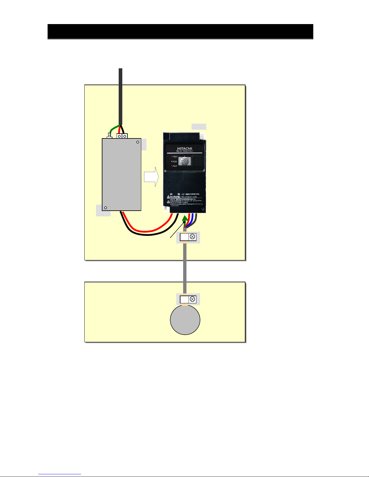
Installation for NE-S1 series (example of SB models)
Model LB (3-ph. 200V class) and HB(3-ph. 400V class) are the same concept for the installation.
*) Both earth portions of the shielded cable must be connected to the ea rth point by ca ble clamp s.
Input choke or equipment to reduce harmonic current is necessary for CE marking (IEC
61000-3-2 and IEC61000-3-4) from the harmonic current point of view, even conducted
emission and radiated emission passed without the input choke.
Shielded cable
Power supply
1-ph. 200V
M
U,V,W
Metal plate (earth)
Earth line is connected to the
heatsink of the inverter
(or PE terminal for bigger models)
PE
EMC filter
(Foot-print)
Cable clamp *
The filter is a footprint type, so it is located
between the inverter and the metal plate.
Remove the insulation material coating of the
earth contact portions so to obtain good
g
rounding condition.
Cable clamp *
Metal plate (earth)
L1,N

Chapter 1 Safety Instructions
1 - 9
Hitachi EMC Recommendations
WARNING
- This equipment should be installed, adjusted, and serviced by qualified personal familiar with
construction and operation of the equipment and the hazards involved. Failure to observe this
precaution could result in bodily injury.
Use the following checklist to ensure the inverter is within proper operating ranges and conditions.
1. The power supply to NE-S1 inverters must meet these specifications:
Voltage fluctuation ±10% or less
Voltage imbalance ±3% or less
Frequency variation ±4% or less
Voltage distortion THD = 10% or less
2. Installation measure:
Use a filter designed for NE-S1 inverter. Refer to the instruction of the applicable external
EMC filter.
3. Wiring:
Shielded wire (screened cable) is required for motor wiring, and the length must be 20
meter or less.
If the motor cable length exceeds the value shown above, use output choke to avoid
unexpected problem due to the leakage current from the motor cable.
The carrier frequency setting must be 2 kHz to satisfy EMC requirements.
Separate the power input and motor wiring from the signal/process circuit wiring.
4. Environmental conditions—when using a filter, follow these guidelines:
Ambient temperature: –10 to 50 °C
(Derating is required when the ambient temperature exceeds 40 °C)
Humidity: 20 to 90% RH (non-condensing)
Vibration: 5.9 m/sec2 (0.6 G) 10 ~ 55Hz
Location: 1000 meters or less altitude, indoors (no corrosive gas or dust)
!

Chapter 1 Safety Instructions
1 - 10
1.3 Precautions Concerning Compliance with UL and cUL Standards
(Standard to comply with : UL508C,CSA C22.2 No.14 -05 )
a) Maximum surrounding air temperature rating of 50ºC.
b) Solid St ate motor overload protection reacts with max. 150 % of FLA.
c) Suitable for use on a circuit capable of delivering not more than 100,000 rms Symmetrical Amperes,
240 Volts Maximum. For models 200V class.
Suitable for use on a circuit capable of delivering not more than 100,000 rm s Symmetrical Amperes,
480 Volts Maximum.For models 400V class.
d) Drive has no provision for motor over temperature protection.
e) When protected by J, CC, G or T Class Fuses. or When protected by a circuit breaker having an
interrupting rating not less than 100,000 rms symmetrical amperes, 240 Volts maximum. For models
200V class.
When Protected by J, CC, G or T Class Fuses. For model s 400V class.
f) Integral solid state short circuit protection does not provide branch circuit protection. Branch circuit
protection must be provided in accordance with the National Electrical Code and any additional local
codes.
g) Install device in pollution degree 2 environment
h) Branch circuit short circuit protection can use fuse or circuit breaker only. For models 200V class..
Branch circuit short circuit protection can use fuse only. For models 400V class..
i) Use 60/75ºC CU wire only.
j) Tightening torque and wire range as sho wn in the table below.
Model No. Required Torque (N.m) Wire Range(AWG)
NES1-002S,004S 0.8~1.0 16~14
NES1-007S 1.8 14~12
NES1-015S 1.8 12~10
NES1-022S 1.8 10
NES1-002L,004L,007L 0.8~1.0 16~14
NES1-015L 1.8 14
NES1-022L 1.8 12
NES1-004H,007H,015H 1.8 16
NES1-022H,040H 1.8 14
j) Distribution fuse and circuit breaker size marking is included in the manual to indicate that the unit
shall be connected with a Listed Cartridge Nonrenewable fuse or Inverse time circuit breaker, rated
600 VAC with the current ratings as shown in the table below:
* In case of using Circuit Breaker, an additional 5 A external protector is needed.
Model No.
Fuse Circuit Breaker
Type Maximum Ratin
g
Type Maximum Ratin
g
NES1-002S,004S
Class J, CC, G or T
10 A
Inverse
Time
15 A
NES1-007S 20 A
NES1-015S,022S 30 A 30 A
NES1-002L*,004L*
Class J, CC, G or T
10 A
Inverse
Time
15 A
NES1-004L*
NES1-007L*,015L 15 A
NES1-022L 20 A 20 A
NES1-004H,007H,
015H,022H,040H
Class J, CC, G or T 15A - -
PD
R
S
T
U
V
W
P
Inverter
Power
supply
Motor
DC link choke
Circuit breaker or
Fuse
Wiring diagram of inverter

Chapter 2 Inspection of the Purchased Product
This chapter describes the inspection of the purchased product, the product
warranty.
2.1 Inspection of the Purchased Product ·············2 - 1
2.2 Method of Inquiry and Product Warranty ········2 - 2


Chapter 2 Inspection of the Purchased Product
2 - 1
2.1 Inspection of the Purchased Product
(A) Inspecting the product
Please check the followings after unpacking.
Please contact your supplier or local Hitachi Distributor
if there are any problems like below on the product.
(1) Any damage duri ng transportation?
(2) Basic manual (English and Japanese) are packed
together with the product?
(3) The product is the one you ordered.
(check with the specification label)
“*” Restricted Distribution
C : China
E : Europe
None : Other (Standard)
-002SB*
200-240
200-240
3.1
1.4
2616200716000001
1206
-001
Example of the specification label
Model name
(NES1-002SB example)
Manufacturing number
Freq.
In
p
ut
Volta
g
e
Phase
Current
Freq.
Output
Volt. & phase
Current
Specification label
Production Management label

Chapter 2 Inspection of the Purchased Product
2 - 2
2.2 Method of Inquiry and Product Warranty
(A) Method of inquiry
In case of contacting to the store you bought the product or Hitachi, please inform the following
information.
(1) Model name of the inverter
(2) Manufacturing number (MFG No.)
(3) When you bought the product
(4) Contents of your inquiry
- Damaged portion and condition, and else.
(B) Product warranty
The product will be warranted for one year after the date of purchase.
Even within the warranty period, repair of a product fault will not be covered by the warranty (but the repair
will be at your own cost) if:
(1) the fault has resulted from incorrect usage not conforming to the instructions given in this
Instruction Manual or the repair or modification of the product carried out by an unqualified person,
(2) the fault has resulted from a cause not attributable to the delivered product,
(3) the fault has resulted from use beyond the limits of the product specifications, or
(4) the fault has resulted from disaster or other unavoidable events.
The warranty will only apply to the delivered inverter and excludes all damage to other equipment and
facilities induced by any fault of the inverter.
Repair at the user's charge
Following the one-year warranty period, any examination and repair of the product will be accepted at your
charge. Even during the warranty period, examination and repairs of faults, subject to the above scope of
the warranty disclaimer, will be available at charge.
To request a repair at your charge, contact your supplier or local Hitachi Distributor.
The Hitachi Distributors are listed on the back cover of this Instruction Manual.
(C) Warranty Terms
The warranty period under normal installation and handling conditions shall be two (2) years from the date
of manufacture (“DATE” on product nameplate), or one (1) year from the date of installation, whichever
occurs first. The warranty shall cover the repair or replacement, at Hitachi’s sole discretion, of ONLY the
inverter that was installed.
(1) Service in the following cases, even within the warranty period, shall be charged to the purchaser:
a. Malfunction or damage caused by mis-operation or modification or improper repair
b. Malfunction or damage caused by a drop after purchase and transportation
c. Malfunction or damage caused by fire, earthquake, flood, lightening, abnormal input voltage,
contamination, or other natural disasters
(2) When service is required for the product at your work site, all expenses associated with field repair
shall be charged to the purchaser .
(3) Always ke ep this QRG handy; please do not loose it. Please contact your Hitachi distributor to
purchase replacement or additional QRG.

Chapter 3 Exterior Views
This chapter describes the exterior views and the names of parts.
3.1 Exterior Views and Names of Parts ···············3 - 1
3.2 Name of each portion
(removing the front cover) ···························3 - 2

Chapter 3 Exterior Views
3 - 1
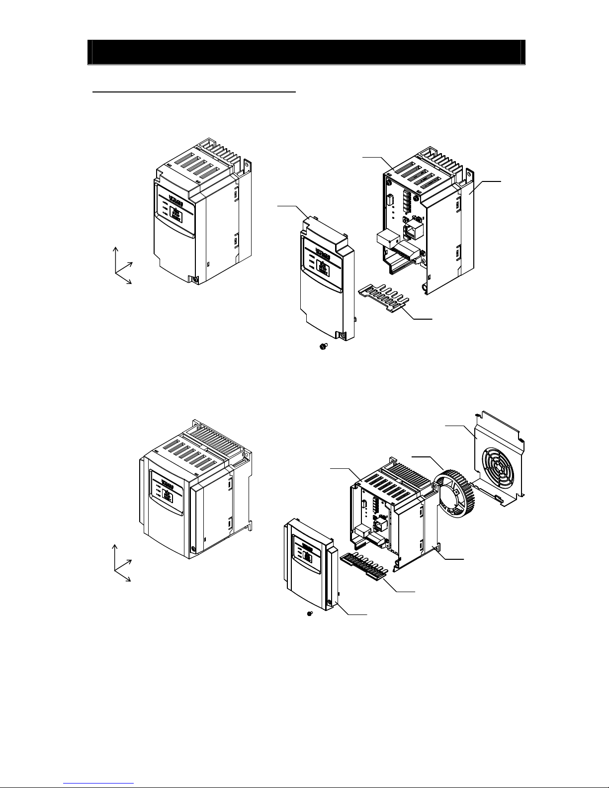
*)002-007SB/LB and 004HB : without Cooling Fan
3.1 Exterior Views and Names of Parts
The figure below shows an exterior view of the inverter
- model : NES1 – 002*,004*SB/LB , 007*LB
- model : NES1 – 007*SB , 015,022SB , 004*,007,015,022HB,040HB
a) Cooling Fan Cover d) Case
b) Cooling Fan e) Front Cover
c) Heat sink f) Backing plate
W
D
H
W
D
H
c
d
e
f
c
d
e
f
b
a
Chapter 3 Exterior Views
3 - 2
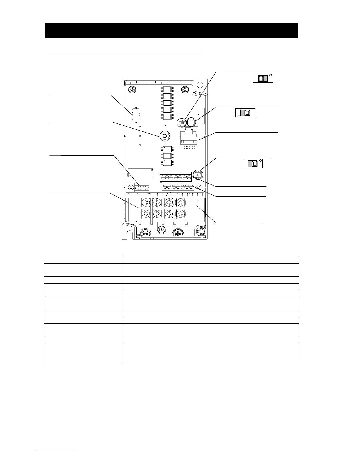
3.2 Name of each portion (removing the front cover) Note1)
Name Description
1) Connector of dedicated operator for
NES1-OP
Dedicated operator for NE-S1 (NES1-OP) can be connected.
2) RUN/STOP/RESET key Push key for run, stop and reset operation.
3) Intelligent relay terminal Output terminal for intelligent relay (1c contact).
4) Main terminal For connecting power supply, motor output and DC reactor.
5) Switch for termination resistor Changeover for integrated resistor (100Ω) for RS485.Integrated resistor of 100Ω is
connected when turning ON.
6) Switch for RS485/OPE Changeover switch for RS422/RS485.
7) RS422/RS485 port Connector for RS485 or external operator and PC software (RJ45 jack)
8) Switch for O/OI (analog input)
changeover
Voltage input (O) or current input (OI) can be selected.
9) Logic terminal A,B Terminal for connecting input/output signals (digital/analog) for the inverter control.
10) Charge lamp Turns ON when the internal DC bus voltage is 45V or more.
In case of wiring, maintenance or else, be sure to check that this lamp is turned OFF after
waiting 10 minutes of power OFF.
Note 1) Refer to section 6.5 How To Operate the Inverter.
Note 2) Position of “10) charge lamp” depends on the model. Refer to page 2-11 for the details.
Note 3) Pay attention when operating by PC via “7)RS422/RS485 port”, because the operation can also be done from the
panel of the inverter.
Note 4) Be sure to turn power OFF when connecting or disconnecting the operator such as OPE-SRmini,OPE-S,WOP to the
“7) RS422/RS485 port”.
Note 5) When communication becomes unstable, Please do not use the termination resistor of the inverter. Please use a
termination resistor suitable for your environment.
6) Switch for RS485/OPE SW5
5) Switch for termination resistor SW4 Note5)
7) RS422/RS485 port Note3) Note4)
2) RUN/STOP/RESET key
4) Main terminal
9) Logic terminal A
section 5.4
8) Switch for O/OI (analog input)
changeover SW6
9) Logic terminal B
3) Intelligent relay terminal
10) Charge lamp Note2)
1) Connector of dedicated
operator for NES1-OP
section 5.4
OFF
(Default)
ON
section 5.4, 8.3
RS485
OPE
(Default)
→section 5.4, 8.3
Voltage O
(Default)
Current OI
section 5.4
section 5.5

Chapter 3 Exterior Views
3 - 3

Chapter 4 Installation
This chapter describes how to install the inverter.
4.1 Precautions for installation ··························4 - 1

 Loading...