


Electromagnetically Compatible Installation Guide Book
Inverter Series
NE-S1
Hitachi Europe GmbH

C O N T E N T S
CHAPTER 1 – WARNINGS AND INSTRUCTIONS ................................................ 1-1
CHAPTER 2 – ELECTROMAGNETICALLY COMPATIBLE
INSTALLATION OF DRIVES AND DRIVE SYSTEMS .......................................... 2-1
INTRODUCTION ............................................................................................................... 2-1
SELECTION OF LINE FILTER TO REDUCE LINE-CONDUCTED INTERFERENCE ...................... 2-2
FILTER INSTALLATION .................................................................................................... 2-3
MINIMIZING RADIATED INTERFERENCE ........................................................................... 2-5
USING EMC COMPLIANT CABLES ................................................................................... 2-6
INSTALLING THE MOTOR CABLE ...................................................................................... 2-7
INSTALLING CONTROL AND SIGNAL LINES ....................................................................... 2-7
SHIELDING AND GROUNDING FOR INSTALLATION IN SWITCH CABINETS ........................... 2-8
CHAPTER 3 – INFLUENCE OF THE MOTOR CABLE LENGTH ....................... 3-1
CHAPTER 4 – FURTHER NOTES.............................................................................. 4-1
INFLUENCE OF GROUND FAULT MONITORING DEVICES .................................................... 4-1
COMPONENTS SUSCEPTIBLE TO INTERFERENCE ............................................................... 4-1
CHAPTER 5 – TECHNICAL SPECIFICATIONS AND DIMENSIONS OF NE-
S1 FILTER ...................................................................................................................... 5-1
CHAPTER 6 –HARMONICS ...................................................................................... 6-1
Chapter 1 – Warnings and instructions
1-1
Chapter 1 – Warnings and Instructions
WARNING The motor cable should be kept as short as possible in order to avoid
electromagnetic emission as well as capacitive currents. The rapid voltage
changes of the Hitachi NE-S1 series cause capacitive currents through the
motor cable stray capacitances.
The cable length increases the capacitive current and electromagnetic
emission.
It is recommended that the motor cable length does not exceed 50m.
It is always recommended to install output AC-Reactors (motor
chokes) if the cable length exceeds 50 m.
WARNING The filters contain capacitors between the phases and the phases to ground
as well as suitable discharging resistors. But after switching off the line
voltage you should wait a minimum of 60 seconds before removing
protective covers or touching terminals etc. Ignore this and you may get an
electric shock!
WARNING The protective conductor connection between filter and drive must be
designed as a solid and permanent installation. Plug-in connections are not
permissible.
WARNING The use of ground fault monitoring devices is not recommended. Should
they be compulsory in certain applications for safety reasons, you should
choose monitoring devices which are suited for DC-, AC- and HF-ground
currents.
WARNING The thermal capacity of the line filter is guaranteed up to a maximum
motor cable length of 50 m.
WARNING The line filters have been developed for use in grounded systems. Use in
ungrounded systems is not recommended.
WARNING The Hitachi NE-S1 series is not intended for sales to general public but a
professional equipment to be used in trades, professions and industries.
If installed according to the following directions, the frequency inverter comply with the
following standards:
Emmissions: EN 61800-3 (EN 55011 group 1, Category C1/C2/C3[Class B/A])
Immunity: EN 61800-3, industrial environments

Chapter 2 – Electromagnetically compatible installation of drives and drive systems
2-1
Chapter 2 – Electromagnetically Compatible
Installation of Drives and Drive Systems
Introduction
This brochure describes the electromagnetically compatible setup of your drive or your drive
system. (Electro Magnetic Compatibility = EMC)
Read this information carefully and follow the instructions. If necessary, provide this infor-
mation to third parties.
HF interference results from rapid switching of electric currents and voltages. All AC, DC and
servo drives very rapidly switch large currents and voltages to optimally supply connected electric
motors. They are thus major sources of interference, generating both line-conducted and radiated
interference.
The additional use of line filters, also called interference suppression filters, and installation in a
metal housing or a switch cabinet further improve the existing interference immunity. For the best
possible damping of interference, special line filters have been developed which guarantee you
easy assembly and installation along with the necessary electrical reliability.
However, effective EMC is only ensured if the suitable filter is selected for the particular drive and
installed in accordance with these EMC recommendations.
Chapter 2 – Electromagnetically compatible installation of drives and drive systems
2-2
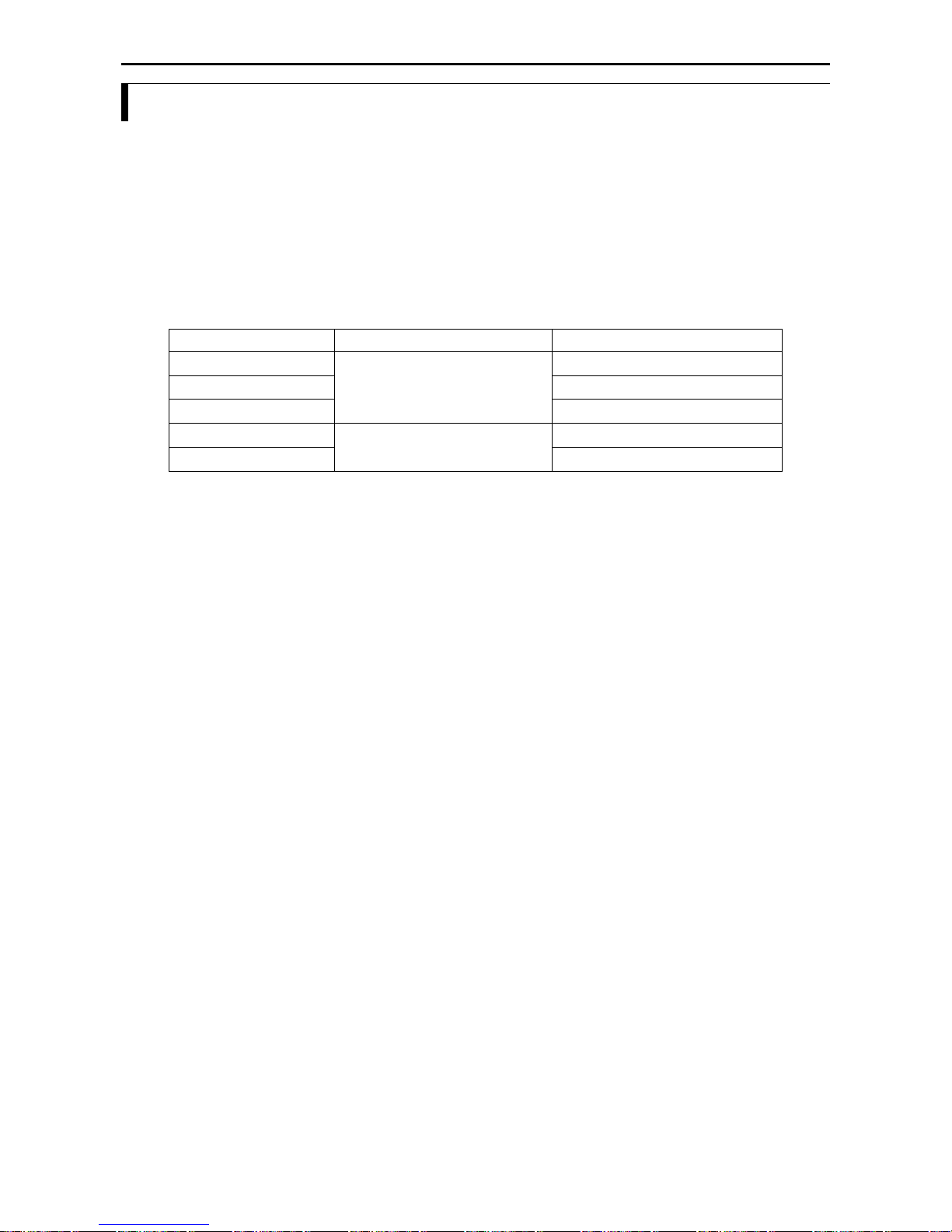
Selection of line filter to reduce line-conducted interference
To reduce line-conducted interference, use the appropriate line filter for each frequency inverter.
The table below show you a list of the available line filters for your Hitachi frequency inverter.
The all line filters are built in the so-called footprint style, are fitted behind the respective
frequency inverter, and thus require no additional space for installation. These filters are intended
for installation in switch cabinets as standard.
Vertical mounting next to the frequency inverter is also possible.
Note: All filters are designed for 50/60Hz.
Frequency Inverter
Line Power spcification
Line Filter
NES1-002,004SBE
1 ~ 200 V -10% to 240V +5%
FPF-9120-10-SW
NES1-007SBE
FPF-9120-14-SW
NES1-015,022SBE
FPF-9120-24-SW
NES1-004,007HBE
3 ~ 380 V -10% to 460V +5%
FPF-9340-05-SW
NES1-015,022,040HBE
FPF-9340-10-SW

Chapter 2 – Electromagnetically compatible installation of drives and drive systems
2-3
Filter installation
The connecting cable between filter and frequency inverter must be as short as possible and laid
separate from other cables/lines.
As user you must ensure that the HF impedance between frequency inverter, filter and ground is as
small as possible:
Remove paint and insulating material between the individual mounting points.
See to it that the connections are metallic and have the largest possible areas.
Use conductive contact grease as anticorrosive.
Anodized and yellow-chromated surfaces, e.g. cable/standard-section rail, screws, etc., have
a large HF-impedance.
This paint must thus be removed at mounting points.
Ensure that the protective conductor terminal (PE) of the filter is properly connected with the
protective conductor terminal of the frequency inverter. An HF ground connection via metal
contact between the housings of the filter and the frequency inverter, or solely via cable shield, is
not permitted as protective conductor connection. The filter must be solidly and permanently
connected with the ground potential so as to preclude the danger of electric shock upon touching
the filter if a fault occurs. You can achieve this by:
connecting it with a grounding conductor of at least 10mm2.
connecting a second grounding conductor, connected with a separate grounding terminal,
parallel to the protective conductor.
The cross section of each single protective conductor terminal must be designed for the required
nominal load.
Conductor loops act like antennas, especially when they encompass large areas. Consequently:
Avoid unnecessary conductor loops.
Avoid parallel arrangement of “clean” and interference-prone conductors over longer
distances.
The line filters have been developed for use in grounded systems. Use of the line filters in
ungrounded systems is not recommended, because in these applications
loss current to ground increases.
the effect of the filter is reduced.
The amount of line-conducted and radiated interference increases in proportion to elementary
frequency in frequency inverter.

Chapter 2 – Electromagnetically compatible installation of drives and drive systems
2-4
The amount of line-conducted interference also increases as motor cable length increases.
Adherence to the interference limits for line-conducted interference is shown as follows:
Filter: FPF-9120-10-SW, FPF-9120-14-SW, FPF9120-24-SW (Switch position 1: High leakage current)
EN61800-3
Cable length
Inverter carrier frequency
Frequency inverter
Category C1
*1
25m Max.
10kHz
NES1-002,004,007,015,022SBE
Category C2
50m Max.
10kHz
*1: The inverter needs to be installed in a metal cabinet to meet category C1. Otherwise category C2.
Filter: FPF-9340-05-SW (Switch position 1: High leakage current)
EN61800-3
Cable length
Inverter carrier frequency
Frequency inverter
Category C2
50m Max.
10kHz
NES1-004,007HBE
Filter: FPF-9340-10-SW (Switch position 1: High leakage current)
EN61800-3
Cable length
Inverter carrier frequency
Frequency inverter
Category C1
*1
25m Max.
10kHz
NES1-015, 022HBE
Category C2
50m Max
10kHz
*1: The inverter needs to be installed in a metal cabinet to meet category C1. Otherwise category C2.
Filter: FPF-9340-10-SW (Switch position 1: High leakage current)
EN61800-3
Cable length
Inverter carrier frequency
Frequency inverter
Category C2
50m Max.
10kHz
NES1-040HBE
Filter: FPF-9120-10-SW, FPF-9120-14-SW, FPF9120-24-SW (Switch position 0: Low leakage current)
EN61800-3
Cable length
Inverter carrier frequency
Frequency inverter
Category C1
*3
5m Max.
10kHz
NES1-002,004,007,015,022SBE
*3: The inverter needs to be installed in a metal cabinet to meet category C1. Otherwise category C2.
Filter: FPF-9340-05-SW, FPF-9340-10-SW (Switch position 0: Low leakage current)
EN61800-3
Cable length
Inverter carrier frequency
Frequency inverter
Category C1
*4
5m Max.
8kHz
NES1-004,007, 015, 022,
040HBE
*4: The inverter needs to be installed in a metal cabinet and ferrite core 2 turns to meet category C1.
Otherwise category C2.

Chapter 2 – Electromagnetically compatible installation of drives and drive systems
2-5
Minimizing radiated interference
The frequency inverter of series NE-S1 meet the limits of EN61800-3, C1/C2/C3, for radiated
interference, if the specified line filter is used and installation is performed according to our
instructions.
The prerequisite is that all analog and digital control lines are laid shielded.
With compact systems, if for example the frequency inverter is communicating with the steering
unit, in the same control cabinet connected at the same PE-Potential, the screen should be put on,
on both sides with PE.
With branch systems, if for example the communicating steering unit is not in the same control
cabinet and there is a distance between the systems, we recommend to put on the screen only on
the side of the frequency inverter. If it is possible, direct in the cable entry section of the steering
unit. This is very important, if there is a long distance between the system and you expect there can
be different PE-Potential between the systems.
You should allow the effective shield area of these lines to remain as large as possible; i.e., do not
move the shield further away than absolutely necessary. The distance between an interference
source and an interference sink (interference-threatened device) essentially determines the effects
of the emitted interference on the interference sink. The interference field emitted by the frequency
inverter falls sharply with increasing distance. Please note that the emitted interference field
(frequency range 30 MHz - 1 GHz) of a drive (drive system) is measured at a distance of 10 m in
accordance with EN61800-3. Every device placed closer than 10 m to a source of interference will
thus be impacted by appreciably higher interference amplitudes. For this reason, you should use
only interference-free devices and maintain a minimum distance of 0.25 m from the drive. Devices
which react sensitively to interference from electric and magnetic fields should be kept at least a
distance of 0.25 m from the following components:
Frequency inverter
EMC input/output filters
Input or output reactors/transformers
Motor cable (even if shielded)
External rheostat and its wiring (even if shielded)
AC/DC commutator motors, including any attached separate fans
DC intermediate circuit coupling/wiring (even if shielded)
Connected inductors like relays, contactors, solenoid valves, brakes (even if shielded)
Very frequently, interference is coupled in through installation cables. You can minimize this
influence by laying interfering cables separately, a minimum of 0.25 m from cables susceptible to
interference. A particularly critical point is laying cables parallel over larger distances. If two
cables intersect, the interference is smallest if they intersect at an angle of 90°. Cables susceptible
to interference should therefore only intersect motor cables, intermediate circuit cables, or the
wiring of a rheostat at right angles and never be laid parallel to them over larger distances.

Chapter 2 – Electromagnetically compatible installation of drives and drive systems
2-6
Using EMC compliant cables
In order to reduce electromagnetic emission caused by motor cables and to increase EMI immunity
for control cables, shielded cables have to be used. Using this shielding can reduce the interference
coupled into and out of the cable (please also refer to the previous chapter „Minimizing radiated
interference“). The effectiveness of the shielding heavily depends on the construction and the
material of the shielding. The screening effectiveness can be characterized by the so called transfer
impedance. This effectiveness or performance can be improved by keeping the transfer impedance
as low as possible. The transfer impedance is mainly affected by the following variables:
The cable covering, which is the cable area actually covered by the shielding. It is normally
indicated as a percentage value and should be at least 85%.
The shielding‘s design. Possible design alternatives are braided cables or shieldings made of
metal conduit. These two types should be preferred when shielding is to be implemented.
The contact (or transition) resistance between the individual stranded conductors of the
shielding. The performance of the shielding improves if this resistance is kept as low as
possible.
The following diagram shows the transfer impedance for various cable types. By comparing the
cables' individual design, the shielding effectiveness can be estimated and a suitable cable be
chosen.
10
-3
10
-2
10
-1
1
10
1
10
2
10
3
10
4
10
5
0,01 0,1 1 10 100
Kopplungsimpedanz
m /m
Frequenz
MHz
1
2
3
4
5
6
Aluminium-Ummantelung
mit Kupferdraht
Gewundener Kupferdraht oder
bewehrtes Stahldrahtkabel
Einlagiges Kupferdrahtgeflecht
mit schwankender prozentualer
Schirmabdeckung
Zweilagiges Kupferdrahtgeflecht
Zweilagiges Kupferdrahtgeflecht
mit magnetisch abgeschirmter
Zwischenlage
In Kupfer- oder Stahlrohr
geführtes Kabel
1
2
3
4
5
6
Bessere
Schirmwirkung
Improving
shielding
performance
Transfer impedance
Aluminum sheating with
copper wire
Meandering copper cable
or armoured steel wire
Single-layer copper wire
braid with varying
percentages of cable
covering
Double-layer copper wire
braid
Double-layer copper wire
braid with magnetically
screened intermediate layer
Cable running in conduit
made of copper or steel

Chapter 2 – Electromagnetically compatible installation of drives and drive systems
2-7
Installing the motor cable
If you use an EMC line filter or would like to observe certain limits of line-conducted interference,
the motor cable which you use must be shielded. The shield is to be grounded on both sides,
over a large area. For this purpose, turn the shield through 180°, for instance, and make large-area
contact (360°) with the metal PG screw connections. The illustration on the following page shows
you the electromagnetically compatible motor wiring.
Use only copper mesh cable (CY) with 85% coverage. Foil shields often have a higher
coupling impedance than mesh shields and are therefore unsuitable.
Some motors have terminal boxes and PG screw connections of plastic. In these cases, the
shield should be connected on the motor side to the motor housing, with as large an area as
possible, by means of a cable clamp.
Some motors have a rubber gasket between terminal box and motor housing. Very often, the
terminal boxes, and particularly the threads for the metal PG screw connections, are painted.
Make sure there is always a good metallic connection between the shielding of the motor
cable, the metal PG screw connection, the terminal box and the motor housing, and carefully
remove this paint if necessary.
The shielding should not be interrupted at any point in the cable. If the use of reactors,
contactors, terminals or safety switches in the motor output is necessary, i.e., if the shield
must be interrupted, then the unshielded section should be kept as small as possible. It is
better to install the reactor, contactor, terminal or safety switch in a metal housing with as
much HF damping as possible. The shield connection to the metal housing should again be
made with the smallest possible HF impedance, as already described.
Should no shielded motor cable be available, lay the unshielded cable in a metal tube having the
best possible shielding effect, for example. The metal tube should have good HF contact with the
frequency inverter and the motor housing, e.g., by means of copper gauze tape. Safety grounding
always takes precedence over HF grounding. If, for example, a braking chopper / rheostat is to
be connected to the DC intermediate circuit, then this connecting line, too, must be shielded. The
shield is to be connected on both sides, with a large area (e.g. to the protective ground terminal of
the rheostat).
Installing control and signal lines
To ensure reliable operation of the frequency inverter, analog and digital control lines (angular
momentum pulser connection, all analog inputs, the serial interfaces, etc.) should be laid shielded.
You should allow the effective shielding surface to remain as large as possible, i.e., do not move
the shield further away than absolutely necessary. The shield has to be applied on both sides on
PE. As a matter of principle, the shielding of these lines should not be interrupted.

Chapter 2 – Electromagnetically compatible installation of drives and drive systems
2-8
Shielding and grounding for installation in switch cabinets
Observe the requirements of European standard EN60204-1, "Electrical Equipment of Industrial
Machinery." You get optimum EMC only if you properly arrange and mount the Hitachi frequency
inverter, the appropriate line filter, and the other equipment which might be necessary, on a metal
mounting plate in accordance with the following mounting instructions. The following figure
shows a Hitachi inverter using a foot print filter:
NE-S1

Chapter 2 – Electromagnetically compatible installation of drives and drive systems
2-9
The following figure shows the required EMC compliant connection to the motor:
good HF-connection between
heat sink and motor housing
required EMC-cable connection
metall box
U V W PE

Chapter 3 – Influence of the motor cable length
3-1
Chapter 3 – Influence of the Motor Cable Length
Shielded motor cables have quite a high cable capacity towards ground, which increases linearly as
cable length increases. A typical rule-of-thumb figure is 200 pF per meter of cable. But these
figures vary among different types of cables and are also dependent on the current-carrying
capacity. Long motor cables can give rise to the following:
Frequency inverter and servo amplifiers give a pulse-width-modulated square-wave output
voltage with quite steep slopes, which causes high reverse-charging currents in the cable
capacities towards ground. This reverse-charging current must be additionally supplied by the
device. Unwanted switch-off due to overload may occur.
Long motor cables produce more line-conducted interference.
Long motor cables lead to the triggering of a ground fault monitoring device that may be
present.
Long motor cables lead to thermal overload of the line filter due to the higher line-conducted
interference.
If a motor choke of appropriate size is used, you have the following advantages:
It can counteract unwanted shut-off due to overload, described above.
The thermal load on the EMC line filter is reduced.
In multiple motor applications, i.e., a frequency inverter feeds several motors connected in parallel,
you should try to minimize the effective cable capacity and/or the effective length of the shielded
cable. You can achieve this by creating a neutral cross-connecting point from which you can
supply all motors.
See to it that the shielding is maintained over the entire length of the cable, if possible, or is only
very briefly interrupted. It is better to install this neutral cross-connecting point in a metal housing
with as much HF damping as possible. The shield connection from/to the metal housing should
again be made with the smallest possible HF impedance, as already described.

Chapter 4 – Further Notes
4-1
Chapter 4 – Further Notes
Influence of ground fault monitoring devices
In the line filter, capacitors are placed between the phases and ground, which can cause larger
charge currents to flow to ground when the filter is first switched on. The amount of this flow has
already been minimized by constructional circuit details. Nevertheless, ground fault monitoring
devices possibly present may be triggered. Ground currents with high-frequency components and
DC components may also flow under normal operating conditions. If faults occur, large DCcarrying ground currents may flow, possibly preventing the ground fault monitoring device from
responding. For this reason, the use of ground fault monitoring devices is not recommended.
But should they be prescribed in certain applications for safety reasons, you should choose
monitoring devices which are suited for DC, AC and HF ground currents. In addition, you should
ensure that their responsiveness and time characteristics are adjustable, so that a disturbance is not
immediately caused the first time the frequency inverter is switched on.
Components susceptible to interference
The following components must be classified as particularly susceptible to interference from
electromagnetic fields. Special attention should therefore be paid to them during installation:
Sensors with analog output voltages (< 1 volt)
Load cells
Tractive force meters
Torque measuring hubs
Resistance thermometer PT100
Thermoelements
Anemometers
Piezoelectric sensors
AM radios (only long and medium wave)
Video cameras and TV sets
Office PCs
Capacitive proximity switches and filling level sensors
Inductive proximity switches and metal detectors
Ripple control transmitters, baby talkers, etc., i.e. all communication devices which use low-
voltage systems as transmission medium
Devices which do not comply with the pertinent EMC requirements

Chapter – Technical specifications and dimensions of NE-S1 filter
5-1
Chapter 5 – Technical Specifications and Dimensions
of NE-S1 Filter
Type: FPF-
Specification:
FPF-9120-10-SW
FPF-9120-14-SW
FPF-9120-24-SW
FPF-9340-05-SW
FPF-9340-10-SW
Voltage in V
240 +5%
240 +5%
240 +5%
460 +5%
460 +5%
Current in A at 40°C
2 x 8A
2 x 14A
2 x 24A
3 x 5A
3 x 11A
Leakage current in
mA/phase/50Hz
worst case
1) 3)
36 (6.1)
55 (4.1)
55 (6.1)
40 (24)
46 (3.4)
Leakage current in
mA/phase/50Hz Un
2) 3)
< 20 (3.1)
< 31 (2.1)
<31 (3.1)
<2.4 (1.3)
<3.8 (0.2)
Test voltage in V DC for 1s
ph./ground
1770
1770
1770
1770
1770
Dimensions
Single wire / litze
6 mm²
6 mm²
6 mm²
6 mm²
6 mm²
Output cable
2x2.5 mm²
2x2.5 mm²
3x4 mm²
3x2.5 mm²
3x2.5 mm²
Weight in kg (approx.)
0.5
1.0
0.9
0.7
1.2
Heat dissipation
in W (approx.)
2 5 10 4 7
1
). “Worst case” states the leakage current for three-phase filters in the worst of cases.
That means one phase is live and two phases of the feed-line lead-in are interrupted.
These maximum values are based on an operating voltage of 460 V (ph./ph.).
2
) The normal leakage current for three-phase filters is stated. This means the filter is
operating on 460 V (ph./.ph.). The stated values are adhered to up to a neutral voltage of
5V to ground caused by line unbalance.
3
) (): Values when switch position is 0 (low leakage current)
Current
at 40°C ambient temperature
Overload
1.5 x IN for 3min
Frequency
50 / 60 Hz
Material
Metal housing
Humidity class
IEC-Clamate-Category acc. to IEC60068-1:
25/100/21

Chapter – Technical specifications and dimensions of NE-S1 filter
5-2
FPF-9120-10-SW
FPF-9120-14-SW/ FPF-9120-24-SW

Chapter – Technical specifications and dimensions of NE-S1 filter
5-3
FPF-9340-05-SW/ FPF-9340-10-SW

Chapter 6 – Harmonics
6-1
Chapter 6 – Harmonics “EN/IEC 61000-3-2 “ and
“EN/IEC 61000-3-12”
Frequency converters, which are connected to the public low voltage power supply must comply
with limits for harmonics currents. For equipment with input current ≤ 16A per phase, the limits
according to EN/IEC 61000-3-2 are applid, and for equipment with input current >16A and ≤ 75A,
the limits according to EN / IEC 61000-3-12 are applied. For professinal equipment with a rated
power > 1kW, no limits are defined in EN/IEC 61000-3-2.
This equipment complies with EN/IEC61000-3-12 provided that the short-circuit power Ssc is
greator than or equal to the value provided in the table below at the interface point between the
user’s supply and the public system. It is the responsibility of the installer or user of the equipment
to ensure, by consultation with the distribution network operator if necessary, that the equipment is
connected only to a supply with a short-circuit power Ssc greater than or equal to the value
mentioned in the table below.
Inverter model
AC/DC
reactor
Norm
Ssc
Rsce
NES1-002,004SBE
3% AC choke
or
4% DC choke
EN/IEC61000-3-2
---
---
Note: NES1-015,022SBE are intended to be connected only to private (industrial) systems.
If these devices are connected to the public low voltage power supply, it must be obtained connection
aproval from the distribution network operator.
If these devices are connected without a AC/DC reactor to the public low voltage power supply, it
must be obtained connection aproval from the distribution network operator.
 Loading...