

Page 1
TECHNICAL DATA
AND
SERVICE MANUAL
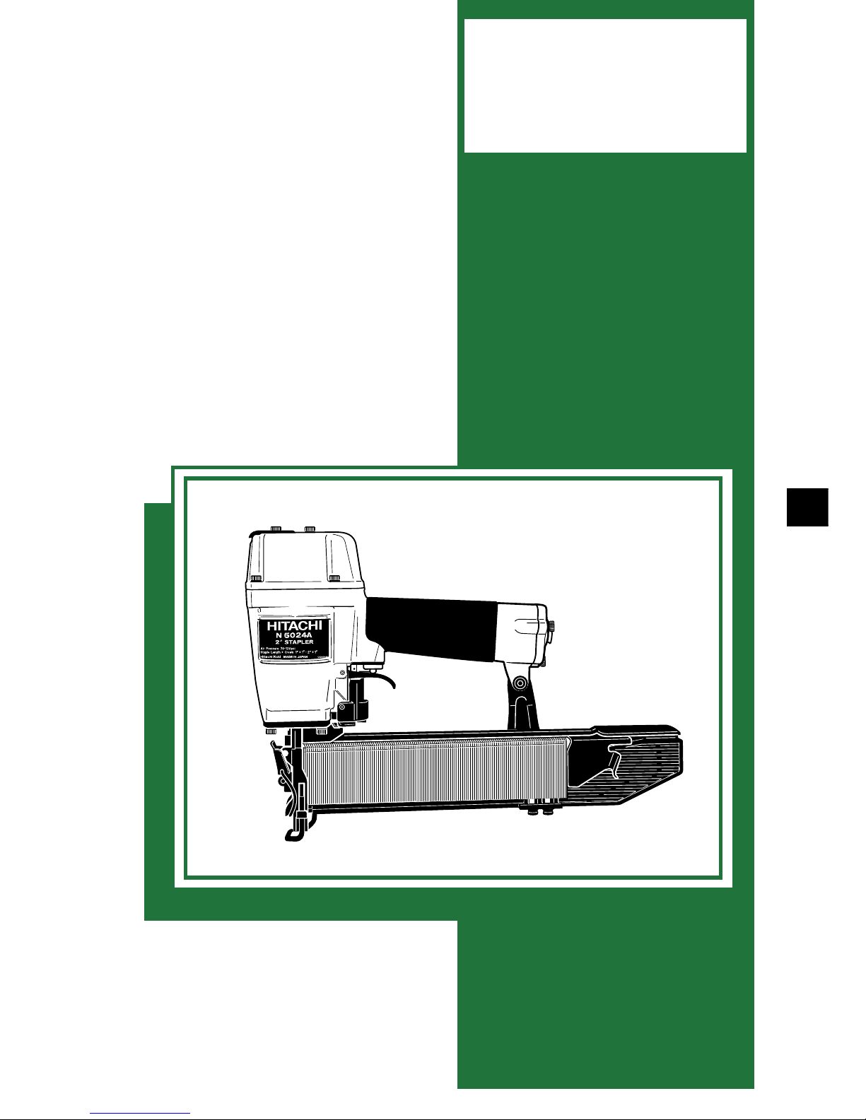
STAPLER
N 5024A
SPECIFICATIONS AND PARTS ARE SUBJECT TO CHANGE FOR IMPROVEMENT
LIST No. E014 Sep. 2003
N
MODEL
N 5024A
Hitachi
Power Tools
Page 2

REMARK:
Throughout this TECHNICAL DATA AND SERVICE MANUAL, a symbol(s)
is(are) used in the place of company name(s) and model name(s) of our
competitor(s). The symbol(s) utilized here is(are) as follows:
Symbols Utilized
Competitors
Company Name
Model Name
SENCO
PW-2”
R
PASLODE
3200-W16
Y
BOSTITCH
450S2
P
Page 3

CONTENTS
Page
1. PRODUCT NAME...........................................................................................................................1
2. MARKETING OBJECTIVE .............................................................................................................1
3. APPLICA TIONS..............................................................................................................................1
4. SELLING POINTS ..........................................................................................................................1
5. SPECIFICATIONS ..........................................................................................................................2
5-1. Specifications................................................................................................................................. 2
5-2. Staple Selection............................................................................................................................. 3
5-3. Staple Driving Force ...................................................................................................................... 4
5-4. Optional Accessories ..................................................................................................................... 4
6. COMPARISONS WITH SIMILAR PRODUCTS..............................................................................5
7. PRECAUTIONS IN SALES PROMOTION .....................................................................................6
7-1. Handling Instructions ..................................................................................................................... 6
7-2. Warning Label................................................................................................................................ 6
7-3. Related Laws and Regulations ...................................................................................................... 7
8. MECHANISM AND OPERATION PRINCIPLE ...............................................................................8
8-1. Mechanism .................................................................................................................................... 8
8-2. Operation Principle ........................................................................................................................ 9
9. TROUBLESHOOTING GUIDE .....................................................................................................13
9-1. Troubleshooting and Correction................................................................................................... 13
9-2. Possible Causes and Correction of Air Leakage ......................................................................... 15
10. DISASSEMBLY AND REASSEMBLY ........................................................................................17
10-1. General Precautions in Disassembly and Reassembly ............................................................. 17
10-2. Disassembly and Reassembly of the Output Section................................................................ 18
10-3. Disassembly and Reassembly of the Control Valve Section ..................................................... 22
10-4. Disassembly and Reassembly of the Driving Section and the Magazine Section..................... 24
11. INSPECTION AND CONFIRMATION AFTER REASSEMBLY ..................................................25
12. STANDARD REPAIR TIME (UNIT) SCHEDULES .....................................................................26
Assembly Diagram for N 5024A
Page 4
--- 1 ---
1. PRODUCT NAME
Hitachi Stapler, Model N 5024A [50 mm (2")]
2. MARKETING OBJECTIVE
The Model N 5024A wide crown stapler has been released following the current Model N 5008AC medium crown
stapler. The new Model N 5024A is expected to expand our share of the stapler market in North America.
Primary differences from the Model N 5008AC are described below.
(1) The weight of the Model N 5024A is 2.1 kg (4.7 lbs.) and it is lighter than our competitors, R, Y and P, thanks to
the adoption of the plastic magazine. The staple shoulder sliding portion of the magazine is wear-resistant.
(2) The driving speed is faster than our competitors thanks to the adoption of the 2-valve/cylinder drive system
that is well reputed in the current Models NV 45AB2, N 5008AC and so on.
(3) The handle is equipped with a cylindrical grip rubber for comfortable fitting and durability.
(4) The driving depth is easily adjustable by tool-less adjuster.
3. APPLICA TIONS
Insulation sheathing
Wire lathing
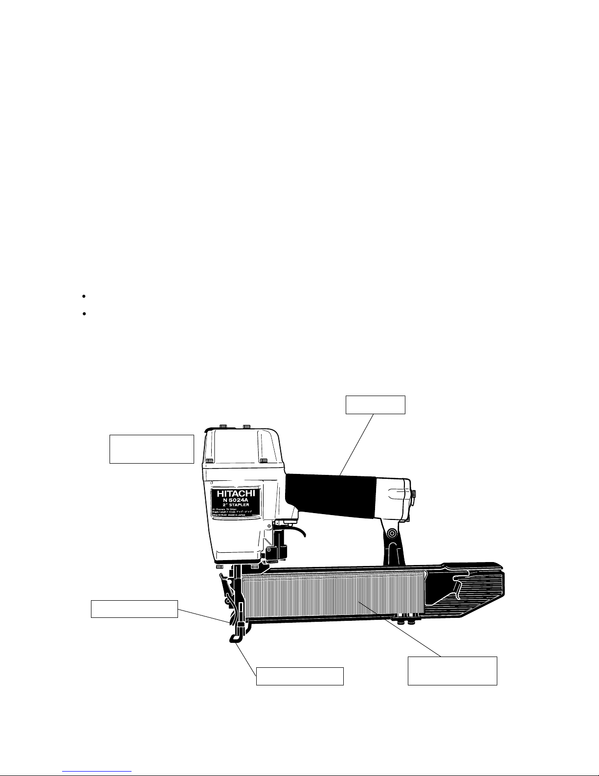
4. SELLING POINTS
Rapid driving and
quick response
Grip rubber
Plastic magazine
with stainless plate
Quick jam-release
Depth adjustment
Page 5
--- 2 ---
Optional accessories
Staple capacity
2.1 kg (4.4 lbs.)
1.05 ltr/cycle at 7 kgf/cm2 (0.037 ft3/cycle at 100 psi) (1.05 ltr/cycle at 6.9 bar)
Corrugated cardboard box
Min. 3 staples/sec.
Driving speed
365 mm x 250 mm x 85 mm
(14-3/8" x 9-13/16" x 3-11/32")
150 staples
Dimensions
(Length x Height x Width)
Staple feed system
3/8" NPT thread
Standard accessories
Weight
Spiral spring
Air consumption
Air inlet
Packaging dimensions
(Length x Height x Width)
Packaging
436 mm x 96 mm x 309 mm
(17-5/32" x 3-25/32" x 12-5/32")
Hex. bar wrench for M5 screw (Code No. 944459)
Safety glasses (Code No. 875769)
Sequential trip mechanism kit (Single-shot) (Code No. 876762)
Pneumatic tool lubricant (1 oz oil feeder) (Code No. 877153)
Pneumatic tool lubricant (4 oz oil feeder) (Code No. 874042)
Pneumatic tool lubricant (1 oz oil feeder) (Code No. 876212)
5. SPECIFICATIONS
5-1. Specifications
Reciprocating piston type
Model
Driving system
N 5024A
Operating pressure
5 --- 8.5 kgf/cm2 (70 --- 120 psi, 4.9 --- 8.3 bar) (Gauge pressure)
Page 6
--- 3 ---
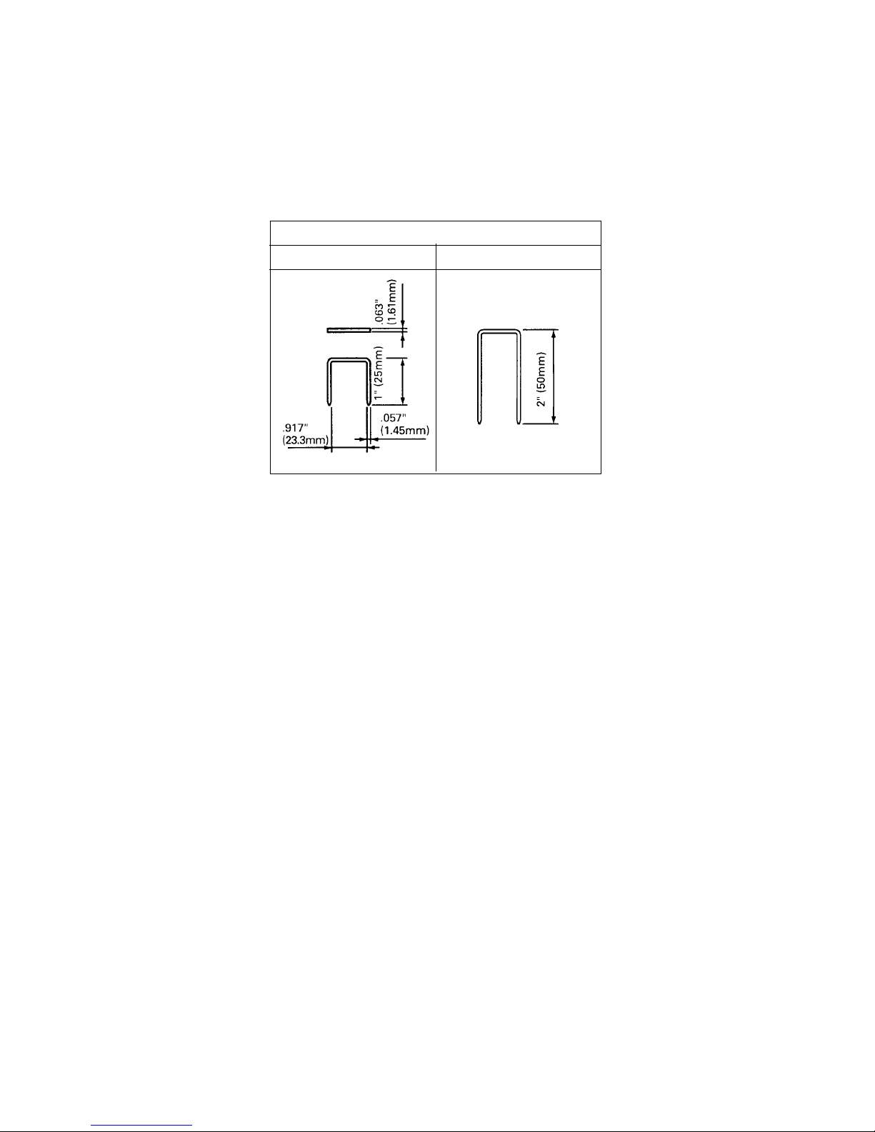
5-2. Staple Selection
The Model N 5024A utilizes medium crown staples, gauge #16, 1" width crown collated by adhesive.
Applicable staple dimensions are shown below.
CAUTION: Ensure that staples are as specified in Fig. 1. Other gauge staples and other crown width
staples will cause clogging of staples and subsequent damage to the stapler.
Minimum
Staple gauge #16, 1" crown
Fig. 1 Dimensions of staple
Maximum
Page 7
--- 4 ---
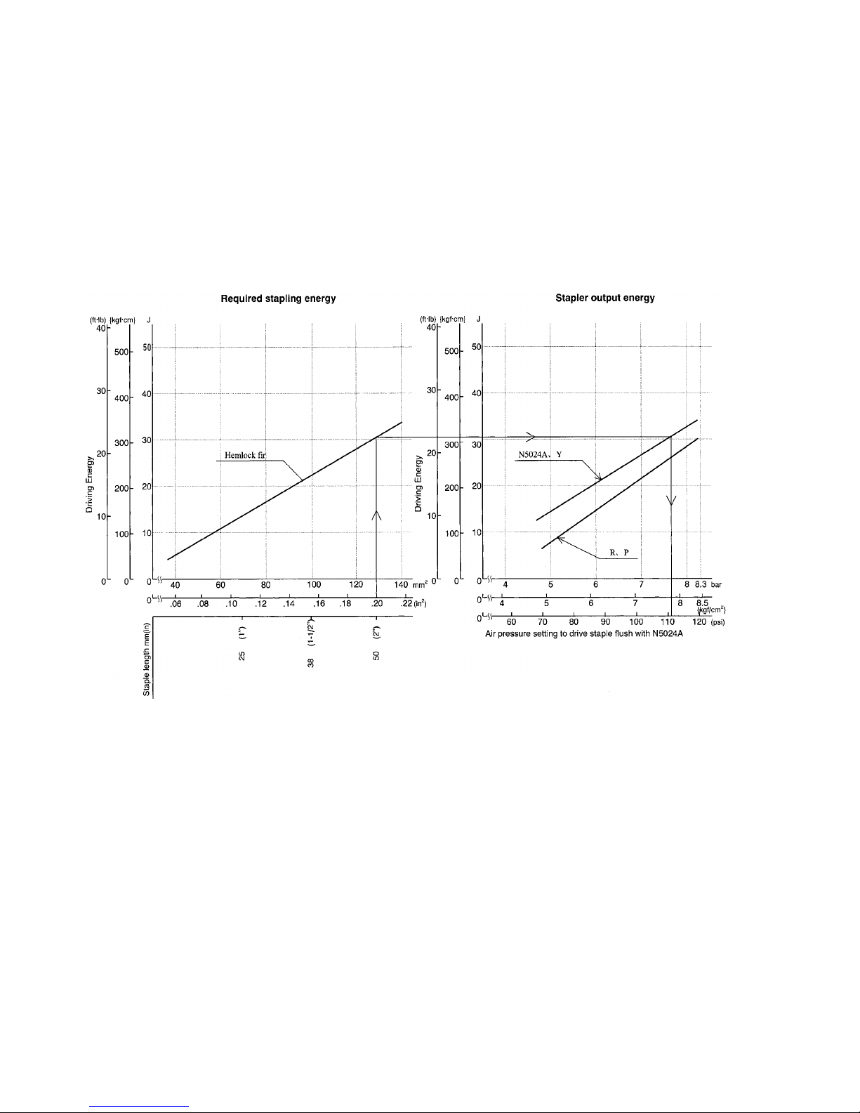
5-3. Staple Driving Force
Figure 2 shows by type of wood and staples, the stapler output energy provided by the supply pressure and the
stapling energy required for driving the staple flush. Air pressure which exceeds the intersecting point between
the stapler output energy and the stapling energy required for driving the staple allows the staple to be fully
driven.
For example, when driving a staple of 50 mm length (2") into a workpiece of hemlock with the Model N 5024A, a
pressure of about 7.7 bar (7.8 kgf/cm2, 111 psi) allows the stapler to drive the staple flush with the wood surface.
A pressure beyond this value causes the staple head to be driven below the wood surface. Figure 2 should be
used as reference data because those values vary depending on the type, moisture content, and grain of wood.
Fig. 2 Required stapling energy and stapler output energy
5-4. Optional Accessories
Sequential trip mechanism kit (Single shot) (Code No. 876762)
A sequential trip mechanism kit is provided as an optional accessory for the Model N 5024A. By using this
optional accessory, a staple is driven by pressing the pushing lever first against a workpiece and then pulling the
trigger (single-shot operation), and no staple is driven when pulling the trigger first and then pressing the pushing
lever against a workpiece. Please recommend the sequential trip mechanism kit to the customers who want to
use it. Salespersons must instruct the customers to read the Handling Instructions attached to the sequential trip
mechanism kit and also the Handling Instructions of the Model N 5024A thoroughly for correct use.
Page 8
--- 5 ---
With wrench
5 to 8.5 kgf/cm
2
(70 to 120 psi)
356 mm x 225 mm x 64 mm
(14" x 8-7/8" x 2-17/32" )
0.91 ltr./cycle
(.032 ft
3
/cycle)
160
2.3 kgf (5.1 lbs.)
P
Single-touch
operation by hand
12.5 mm to 50 mm
(1/2" to 2")
22.2 mm (.874")
1/2"
Driving depth
adjustment mechanism
Single-touch
operation by hand
None
6. COMPARISONS WITH SIMILAR PRODUCTS
Maker
HITACHI
Air consumption at
7 kgf/cm
2
(100 psi)
Operating pressure
Jam-release
Weight
Dimensions
(L x H x W)
Model name
Staple capacity (Max.)
5 --- 8.5 kgf/cm
2
(70 --- 120 psi)
365 mm x 250 mm x 85 mm
(14-3/8" x 9-13/16" x 3-11/32")
N 5024A
1.05 ltr./cycle
(.037 ft
3
/cycle)
150
Single-touch
operation by hand
2.1 kgf (4.7 lbs.)
5.6 --- 7.7 kgf/cm
2
(80 --- 110 psi)
318 mm x 241 mm x 69 mm
(12-1/2" x 9-1/2" x 2-3/4" )
0.95 ltr./cycle
(.034 ft
3
/cycle)
140
2.5 kgf (5.4 lbs.)
R
With tool
Applicable
staples
#16 gauge
wire
Length
Inside width
25 mm to 50 mm
(1" to 2")
23.3 mm (.917")
Outside width
1"
25 mm to 50 mm
(1" to 2")
23.3 mm (.917")
1"
With wrench
4.2 to 8.4 kgf/cm
2
(60 to 120 psi)
356 mm x 241 mm x 80 mm
(14" x 9-1/2" x 3- 1/ 8" )
0.99 ltr./cycle
(.035 ft
3
/cycle)
150
2.2 kgf (4.9 lbs.)
Y
Single-touch
operation by hand
19 mm to 50 mm
(3/4" to 2")
20.4 mm (.803")
15/16"
Page 9
--- 6 ---
7. PRECAUTIONS IN SALES PROMOTION
In the interest of promoting the safest and most efficient use of the Model N 5024A Stapler by all of our customers,
it is very important that at the time of sale the salesperson carefully ensures that the buyer seriously recognizes
the importance of the contents of the Handling Instructions, and fully understands the meaning of the precautions
listed on the Warning Label attached to each tool.
The Model N 5024A Stapler is designed for continuous staple driving. At time of sale, the salesperson must
inform the customer that the sequential trip mechanism kit which can change the Model N 5024A to a single-shot
stapler is optionally available, and recommend it to the customers who want to use it. Refer to the leaflet attached
together with the Handling Instructions for details.
7-1. Handling Instructions
Although every effort is made in each step of design, manufacture, and inspection to provide protection against
safety hazards, the dangers inherent in the use of any pneumatic tool cannot be completely eliminated.
Accordingly, general precautions and suggestions for use of pneumatic tools, and specific precautions and
suggestions for the use of the pneumatic stapler are listed in the Handling Instructions to enhance the safe,
efficient use of the tool by the customer.
Salespersons must be thoroughly familiar with the contents of the Handling Instructions to be able to offer
appropriate guidance to the customers during sales promotion.
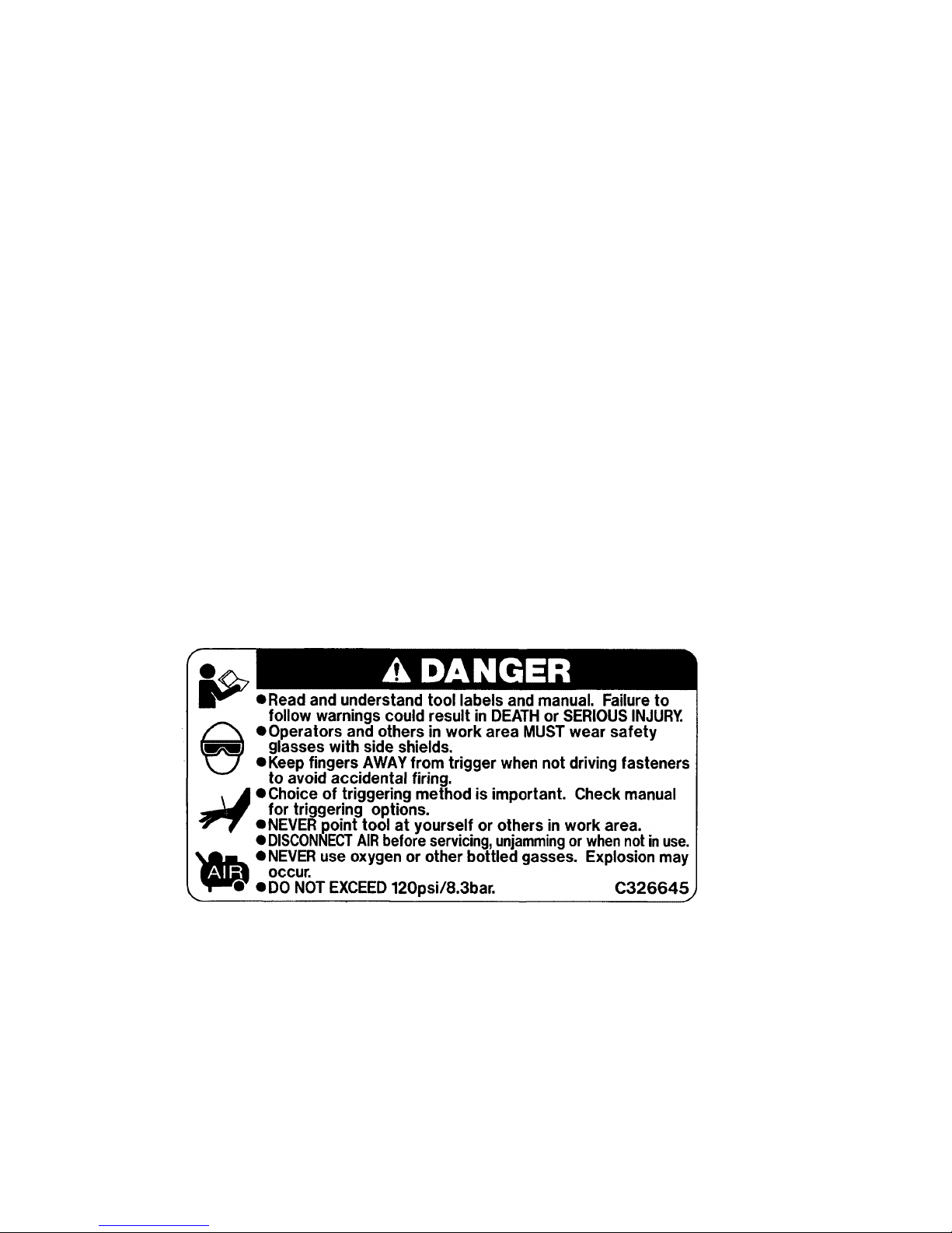
7-2. Warning Label
Each Model N 5024A unit is provided with a Warning Label (illustrated below) which lists basic safety precautions
in its use. Carefully ensure that customers fully understand and follow these precautions before using the tool.
Page 10

--- 7 ---
7-3. Related Laws and Regulations
As nailers and staplers are designed to instantaneously drive nails and staples, there is an ever-present danger of
misfiring and subsequent possible serious injury. Accordingly, close attention in handling is absolutely necessary
at all times. Carefully ensure that the customer is fully aware of the precautions listed in the Handling Instructions
provided with each unit.
While there are no specific safety regulations, there are related items in various general safety regulations with
which the salespersons should be familiar in order to properly advise the customer. Please check your national
and/or local regulations for applicable items. Some applicable items are outlined below.
The U.S.A:
OSHA 1926.102 Eye and face protection
1926.302 Power-operated hand tools
ANSI SNT-101-1993 Portable, Compressed-Air-Actuated,
Fastener Driving Tools-Safety Requirements for
Page 11
--- 8 ---
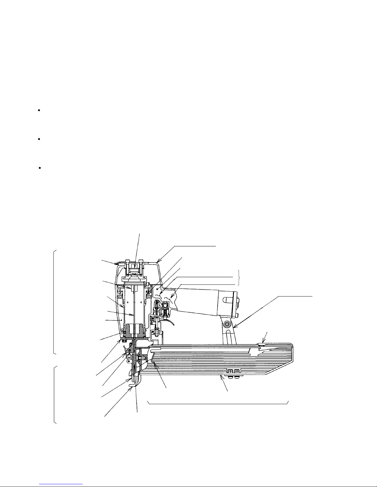
8. MECHANISM AND OPERATION PRINCIPLE
8-1. Mechanism
As illustrated in Fig. 3, the Model N 5024A can be generally divided into four sections:
output section, control valve section, driving section and magazine section.
The driving section (nose and piston) and the magazine section have been newly designed though its basic
construction is the same as that of the Model N 5008AC (valve section is common to the Model N 5008AC).
Primary differences from the Model N 5008AC are described below.
Output section
........
The piston (driver blade) has been newly designed according to the shape of the
staple firing gate. Owing to the enlargement of the driver blade, the piston bumper has
been newly designed.
Driving section
........
All the parts have been newly designed for driving staples.
If staples are clogged in this section, they can be easily released simply by pulling
the lock lever by hand.
Magazine section
....
All the parts have been newly designed for driving staples.
The magazine cover is opened by pulling the staple feeder backward for easy loading or
replacement of staples.
The <Bold> numbers in the figure below correspond to the numbers in "8-2. Operation Principle".
Fig. 3 Construction
Exhaust Vent < 3 >
Return Air
Chamber < 8 >
Driver Blade < 7 >
Cylinder < 6 >
Piston < 4 >
Piston
Bumper < 9 >
Nose <10>
Blade guide
Pushing lever (A)
Accumulator < 1 >
Control valve
section
Exhaust cover
Cylinder Spring <5>
Trigger valve portion
Magazine ass'y
Staple feeder
Magazine section
Safety valve portion
Driving section Output section
Exhaust Valve < 2 >
Lock lever
Firing gate
Handle arm
Magazine cover
Guide plate
Page 12

--- 9 ---
8-2. Operation Principle
The operation of the Model N 5024A is illustrated and described in Fig. 4 through 7. The circled numbers in the
descriptions correspond to the item numbers shown in the mechanism illustrated in Fig. 3. In Fig. 5 and Fig. 7,
read the descriptions in alphabetical order.
Fig. 4 When the compressed air source (air hose) is connected to the nailer
Air pressure is applied to the lower surface of the flanges
located at the center portion of the Cylinder < 6 >, forcing
the cylinder upward. The compressed air is thereby
blocked from the upper end of the cylinder, and no pressure
is applied to the piston.
The Accumulator < 1 > fills with
compressed air.
The trigger and pushing lever are not
operated, and remain closed.
The exhaust vents are opened and no air pressure is
applied to the valve air passage.
Page 13

--- 10 ---
Fig. 5 When the trigger and pushing lever are operated
Although air pressure is applied to both the
upper and lower sides of the cylinder, the
cylinder is forced downward due to the larger
effective area of the upper side.
Accordingly, the upper portion of the cylinder is
opened, and the compressed air forces the
piston downward.
When the trigger and pushing lever are operated
simultaneously, the safety valve and trigger valve
are opened.
The trigger and pushing lever are operated
simultaneously.
(NOTE)
If either the trigger or pushing lever is
operated individually, compressed air will
not enter the valve air passage, and the
nailer will not function.
When the trigger and pushing lever are
operated simultaneously, the exhaust
vents are closed.
Compressed air is applied
to the upper side of the
Exhaust Valve < 2 >, forcing
it downward and closing
the Exhaust Vent < 3 >.
As the piston moves downward, the air below the piston
is forced into the Return Air Chamber < 8 >.
When the piston passes the middle vent, some of the air passes
into the return air chamber. This supplies auxiliary air to ensure
complete return of the piston.
Cylinder ring
Page 14

--- 11 ---
Fig. 6 When the trigger and the pushing lever are kept pressed
Air pressure is applied in the shaded areas in the
illustration, and each component is held in the
position illustrated.
The lower surface of the Piston < 4 > contacts
the Piston Bumper < 9 > and prevents air
leakage. If the upper surface of the Piston
Bumper < 9 > is damaged, some air will leak.
As there is no o-ring installed here, a
very small amount of air will leak from
the slight clearance between the
components.
If the operator's grip is
loosened, air will leak.
Page 15

--- 12 ---
Fig. 7 When the trigger and/or the pushing lever are released
The air pressure on the upper surface of the Exhaust Valve < 2 > is
released, and the exhaust valve is pushed upward by the air pressure
within the cylinder. This opens the Exhaust Vent < 3 >, and the air
pressure in the cylinder is discharged from the nailer.
Air pressure is discharged from the upper end of
the cylinder, and the cylinder is pushed upward by
the air pressure on the lower surfaces of the
flanges and the force of the Cylinder Spring < 5 >.
This closes the upper end of the cylinder, and
blocks compressed air from entering the cylinder.
At the time the piston returns, any remaining air pressure at the lower
end of the piston is discharged through the clearance between the
Piston Bumper < 9 > and the Driver Blade < 7 >.
When the air pressure at the upper side
of the piston lowers, the air pressure
within the Return Air Chamber < 8 >
pushes the piston upward.
(NOTE) If the clearance were larger, the
piston would not return: if it were
smaller, driving force would be
decreased.
When the trigger is released, the trigger valve closes
and the air pressure within the valve air passage is
discharged through Valve Exhaust Vent I .
In addition, when the pushing lever is lifted from
the wood surface, the safety valve closes, and
the air pressure within the valve air passage is
discharged through Valve Exhaust Vent II .
(The illustration shows both the trigger and
pushing lever released.)
Valve Exhaust Vent II
Valve Exhaust Vent I
Page 16

--- 13 ---
<Magazine>
Staple feeder abnormal
(burrs, deformed,
damaged).
<Staples>
The magazine is not loaded
with specified genuine
staples.
Problem
Possible cause
( : most-common cause)
Inspection method Remedy
Correct the burred or
deformed portion.
Replace the defective part.
9. TROUBLESHOOTING GUIDE
9-1. Troubleshooting and Correction
1) Staples
cannot
be driven.
Check if the magazine is
normally loaded with
specified staples.
Check if they move
smoothly after putting
staples and check if the
staple feeder operates
smoothly.
Check the staple feeding
section for abnormal
conditions (burrs, fatigued,
deformed, damaged).
Check if staples can be
driven at 5 kgf/cm2 (
4.9 bar,
70 psi
).
Use specified staples.
After removing the adhesive
fragments and wood chips,
apply oil to the staple
feeder.
The magazine is loaded
with abnormal staples (bent
staples, abnormal collation,
other).
Remove the abnormal
staples and load the
magazine with normal
staples.
Ribbon spring abnormal
(fatigued, damaged).
Staple rail width too wide.
Magazine cover abnormal
(deformed, damaged).
Adhesive fragments and
wood chips are on the
magazine, staple feeder or
staple rail.
Replace the defective part.
Replace the defective part.
Replace the defective part.
Cylinder's internal surface
abnormal (deposites of dirt,
worn).
Driver blade abnormal
(deformed, burrs,
damaged).
Cylinder ring abnormal.
(dislocated, deformed,
damaged).
Piston bumper abnormal.
Replace the piston bumper.
Reassemble or replace.
Touch up or replace.
After removing the dirt,
apply oil or replace.
Piston O-ring worn.
Air pressure too low.
Keep the staple feeder
ass'y pulling backward and
perform idle driving. Then
check that the driver blade
returns to its original
position.
Adjust for 5 to 8.5 kgf/cm
2
(4.9 --- 8.3 bar, 7 --- 120 psi).
<Output section: Piston,
driver blade, etc.
>
Replace the piston O-ring.
Pushing lever incorrectly
adjusted.
Check adjustment.
Adjust the protruded amount
within 4 0.5 mm
(0.157" 0.02").
<Pushing lever>
Page 17

--- 14 ---
Adjust the adjuster for the
proper position.
Adjust for 5 to 8.5 kgf/cm
2
(4.9 --- 8.3 bar, 70 --- 120 psi)
.
Unusable because the tool
is not designed for such
usage.
Replace the part.
Replace the defective part.
Replace the defective part.
Use specified staples.
See <Magazine> in item 1).
Replace the part.
See <Output section:
Piston, driver blade, etc.> in
item 1).
< Improper staple feed >
See <Magazine> in item 1).
Driver blade worn.
< The driver blade has not
returned completely.
>
See <Output section:
Piston, driver blade, etc.>
in item 1).
Staples are not fully fed into
the injection port.
Unspecified staples used.
Driver blade worn.
The material being driven
into is very hard.
The adjuster is improperly
adjusted.
Air pressure too low.
The material being driven
into is very hard.
Driver blade worn.
Piston O-ring abnormal
(worn, damaged).
Cylinder's internal surface
abnormal (worn, rough).
Unspecified staples used.
Problem
Possible cause
( : most-common cause)
Inspection method Remedy
2) Staples bent
while being
driven.
See item 1).
See item 1).
Check if the driver blade tip
is abnormally worn.
Check if a staple is bent
even when driven into soft
wood.
See item 1).
See item 1).
Replace the part.
Unusable because the tool
is not designed for such
usage.
3) The staple is
driven into the
material but
the head is
raised above
the surface.
Turn the adjuster to the
lowest position, then drive.
Drive the staple into soft
wood and check if the head
is raised or not.
Check if the driver blade tip
is worn.
Disassemble the output
section and check the
piston O-ring and the
internal surface of the
cylinder for abnormal
condition.
Check if the staples are
specified ones.
Check if they move
smoothly after putting
staples, and check if the
staple feeder operates
smoothly.
Check if the driver blade tip
is worn.
Perform idle driving or
actually drive with staples,
and check if the driver
blade has returned
completely.
4) Staples clog
the
mechanism.
Page 18

--- 15 ---
9-2. Possible Causes and Correction of Air Leakage
Air leakage repair location
Page 19

--- 16 ---
Cylinder [14] does not return.
Swollen Cylinder O-ring (D) [12] (Use of
unsuitable oil causes swelling. Advise the
customer to use Shell Tonna Oil S32.)
Deformed Cylinder [14] or Cylinder Guide [18].
Yielded or broken Cylinder Spring [16].
Defective Head Cap Ass'y [8] (worn rubber
portion or broken)
Broken Gaskets (C) [6]
Loose Hex. Socket Hd. Bolt M5 x 25 [1]
Broken Exhaust Cover [4]
Loose Hex. Socket Hd. Bolt M5 x 20 [3]
Broken Gasket (B) [5]
Damaged seal surfaces of Body Ass'y [21]
and Exhaust Cover [4]
Damaged Cylinder O-ring (B) [19] or O-ring
of Cylinder Guide [18] (worn, deformed or
broken)
Defective Body Ass'y [21] (worn, corroded or
deformed)
Defective Urethane Ball (C) D7.14 [62]
(damaged or deformed)
Defective ball sheet surface of Trigger Valve
Bushing [64] (damaged, deformed or worn)
Defective Valve Packing [61] (damaged,
deformed or broken)
Soiled or damaged valve packing sheet
surface of Body Ass'y [21]
Incursion of foreign materials
Defective Gaskets (B) (C) [5] [6] (damaged or
yielded)
Discorded air vent of Gasket (B) [5]
Defective O-ring (S-65) [11] or Cylinder
O-ring (D) [12] of the Cylinder Plate [13]
(worn, deformed or broken)
Defective Cylinder O-ring (D) [12] (worn,
deformed or broken)
Loose Hex. Socket Hd. Bolt M5 x 16 [42]
Broken Gasket (D) [40]
Defective seal surface of the Body Ass'y [21]
or Cap [41]
Defective Exhaust Valve
[7] (worn, deformed, or
broken)
Exhaust vent
Air leak part
Cause
When trigger valve/safety valve are OFF
When trigger valve/
safety valve are ON
Inspection priorities:
In the table below, possible causes of air leakage and their repair procedures are marked in accordance with the
likelihood of possible failure.
(1) First priority items are marked with an asterisk ( ).
(2) Second priority items (seal portions) are marked with a double circle ( ).
(3) Remaining items are marked with a single circle ( ). (See Parts List and exploded assembly diagram for part
name and location.)
Deformed Nose [26]
Loose Nylock Hex. Socket
Hd. Bolt M5 x 16 [27]
Broken Gasket (A) [25]
When trigger valve ON/
safety valve OFF
A
Exhaust cover
B
Nose
C
Nose
D
Trigger valve
E
Safety valve
F
Cap
G
Air will leak slightly from
the lower portion due to
construction.
Defective Plunger O-ring
[57] (worn, deformed or
broken)
Defective outside
O-ring (S-12) [58] of
Trigger Valve Bushing
[64]
Broken or cracked
Piston Bumper [23]
Deformed Piston [10]
Deformed Nose [26]
Defective outside O-ring
(S-12) [58] of the Valve
Bushing [59] (worn,
deformed or broken)
Defective Plunger O-ring
[57] (worn, deformed or
broken)
Defective Plunger Spring
[55] (deformed or broken)
Defective safety Valve
Bushing [59] (deflected,
deformed or broken)
Page 20

--- 17 ---
10. DISASSEMBLY AND REASSEMBLY
The items particularly necessary for disassembly and reassembly are described below. The [Bold] numbers in
the descriptions below correspond to the item numbers in the Parts List and exploded assembly diagram.
[CAUTION]
Before disassembly or reassembly, be sure to remove all staples and disconnect the air hose from the
stapler (with your finger released from the trigger) to exhaust all the compressed air.
10-1. General Precautions in Disassembly and Reassembly
Apply grease (Nippeco SEP-3A, Code No. 930035) to the O-rings and O-rings' sliding portions.
When installing the O-rings, be careful not to damage the O-rings and prevent dirt entry.
Oil required: Hitachi pneumatic tool lubricant
1 oz (30 cc) oil feeder (Code No. 877153)
4 oz (120 cc) oil feeder (Code No. 874042)
1 quart (1 ltr) can (Code No. 876212)
If Gasket (B) [5] is damaged, replace it and check that no air is leaking.
Be especially careful to prevent the entry of foreign particles into the control valve section.
Use the conventional grip tape for repair of the grip rubber because the grip rubber cannot be mounted without
the specifically designed jig.
Tightening torque for each part
Bolt and screw
Tightening torque
N•m (kgf•cm, ft-lb.)
Hex. Socket Hd. Bolt M5 x 25 ....................................... [1]
8.3 0.5 (85 5, 6.1 0.4)
Nylock Hex. Socket Hd. Bolt M5 x 16 ........................... [27]
Hex. Socket Hd. Bolt M5 x 20 ....................................... [3]
Hex. Socket Hd. Bolt M5 x 10 ....................................... [29]
Hex. Socket Hd. Bolt M5 x 16 ....................................... [42]
Hex. Socket Hd. Bolt M5 x 18 ....................................... [34]
1.9 0.5 (20 5, 1.4 0.4)
Machine Screw (W/Sp. Washer) M5 x 16 (Black)......... [47]
Machine Screw (W/Washers) M5 x 14 (Black).............. [78]
Page 21

--- 18 ---
10-2. Disassembly and Reassembly of the Output Section
(1) Piston [10], Cylinder [14] and the related parts
Tool required:
Hexagonal bar wrench (4 mm)
(a) Disassembly (See Figs. 8, 9 and 10.)
Remove the four Hex. Socket Hd. Bolts M5 x 20 [3], and take off the Exhaust Cover [4]. The Piston [10]
can then be taken out.
Next, as illustrated in Fig. 9, screw two of the previously removed Hex. Socket Hd. Bolts M5 x 20 [3] into the
provided holes on the Cylinder Plate [13].
Gripping these two bolts, simultaneously turn and pull upward to remove the Cylinder Plate [13]. When this
has been accomplished, the Cylinder [14] and other parts which make up the output section can be
removed, as illustrated in Fig. 10.
If it is difficult to remove the Cylinder [14], remove the Nose [26] by referring para. 10-2-(3) procedures, and
push out the Cylinder [14] from the lower part of the main body.
(b) Reassembly
Reassembly can be accomplished by following the disassembly procedures in reverse. However, special
attention should be given to the following items.
Reassembly of the Piston [10] can be most easily accomplished by inserting the Piston [10] into the
Cylinder [14] as illustrated in Fig. 11, and insertng the Piston [10] into the grooves on the Nose [26] while
pulling the piston out in a downward direction.
When assembling Gasket (B) [5], ensure that its air vents are properly aligned with the air vents on Body
Ass'y [21].
Tighten the four Hex. Socket Hd. Bolts M5 x 20 [3] to specified torque (85 5 kg• cm, 6.1 0.4 ft-lb).
There is no directivity of Piston [10] in the assembly of Piston [10].
Fig. 9Fig. 8
Exhaust Cover [4]
Piston [10]
Gasket (B) [5]
Cylinder Plate [13]
Cylinder [14]
Body Ass'y [21]
Hex. Socket Hd. Bolt M5 x 20 [3]
Cylinder Plate [13]
Threaded hole
for M5 bolts
Hex. Socket Hd. Bolt M5 x 20 [3]
Page 22

--- 19 ---
Fig. 10
Fig. 11
Piston [10]
Cylinder
Guide [18]
Piston [10]
Cylinder Ring [15]
Cylinder [14]
Cylinder Plate [13]
Body
Ass'y
[21]
Page 23

--- 20 ---
(3) Piston Bumper [23] and the related parts (See Fig. 13.)
Tools required
Hexagonal bar wrench (4 mm)
Roll pin puller (3 mm (0.118") dia.)
8 mm (0.315") spanner
(a) Disassembly
Pull out the Roll Pin D3 x 45 [46] and remove the Hex. Socket Hd. Bolt M5 x 18 [34] to remove the Guard
[36].
Remove the Machine Screw (W/Washers) M5 x 14 (Black) [78] and pull out the entire magazine section
from the Handle Arm [69].
Remove the Machine Screw (W/Sp. Washers) M5 x 16 (Black) [47] and pull out the entire magazine section
from the Nose [26].
Remove the four Nylock Hex. Socket Hd. Bolt M5 x 16 [27]. Then Piston Bumper [23] can be removed
together with the Nose [26].
Remove the Hex. Socket Hd. Bolts M5 x 10 [29]. Then Guide Plate [28], Blade Guide [31], etc. can be
removed.
(b) Reassembly
Disassembly procedures should be followed in the reverse order. Note the following points.
Plunger (B) [60] is apt to come off during disassembly. Be sure to check that Plunger (B) [60] is securely
mounted during reassembly.
Mount the Roll Pin D3 x 45 [46] without fail.
Fig. 12
Head Cap Ass'y [8]
Exhaust Cover [4]
Hex. Socket Hd.
Bolt M5 x 20 [3]
Top Cover [2]
Hex. Socket Hd.
Bolt M5 x 25 [1]
Exhaust Valve [7]
Gasket (C) [6]
Gasket (B) [5]
Tool required:
Hexagonal bar wrench (4 mm)
(a) Disassembly
As described in paragraph 10-2-(1), remove the Exhaust
Cover [3].
Remove the two Hex. Socket Hd. Bolts M5 x 25 [1] and,
such as illustrated in Fig. 12, disassemble the Head Cap
Ass'y [8], the Exhaust Valve [7] and Gasket (C) [6] in that
order.
(b) Reassembly
Reassembly can be accomplished by following the
disassembly procedures in reverse. Ensure that the Hex.
Socket Hd. Bolts M5 x 25 [1] are properly tightened to
specified torque (85 5 kgf• cm, 6.1 0.4 ft-lb.).
(2) Head Cap Ass'y [8], Exhaust Valve [7] and the related parts (See Fig. 12.)
Page 24

--- 21 ---
Fig. 13
Guide Plate [28]
Nylock Hex. Socket
Hd. Bolt M5 x 16 [27]
Magazine Ass'y [77]
Valve Guard
[45]
Bumper Sheet [24]
Piston Bumper [23]
Nose [26]
Machine Screw (W/Washers)
M5 x 14 (Black) [78]
Nylon Nut M5 [39]
Roll Pin
D3 x 45
[46]
Roll Pin
D4 x 16 [30]
Handle Arm [69]
Body Ass'y [21]
Hex. Socket Hd.
Bolt M5 x 18 [34]
Gasket (A) [25]
Machine Screw
(W/Sp. Washer)
M5 x 16 (Black)
[47]
Blade Guide [31]
Guard [36]
Washer [35]
Sleeve [37]
Nylon Nut M5 [39]
Hex. Socket Hd.
Bolt M5 x 10 [29]
Page 25

--- 22 ---
(a) Disassembly (See Fig. 14.)
Remove the driving section and the magazine section as described in section 10-2-(3).
With the roll pin puller (3 mm (0.118") dia.), take out the Roll Pin D3 x 30 [68], and remove the Trigger [67],
Trigger Plunger [66] and Plunger (B) [60].
Insert the flat-blade screwdriver into the groove of the Trigger Valve Bushing [64], and loosen it by turning it
to the left, being careful not to damage the groove.
After removing the Trigger Valve Bushing [64], pull down strongly on the Valve Bushing [59] to remove the
Valve Bushing [59], Plunger (A) [56] and the Plunger Spring [55].
10-3. Disassembly and Reassembly of the Control Valve Section
Tools required:
Roll pin puller (3 mm (0.118") dia.)
Flat-blade screwdriver
Fig. 17
Trigger [67]
Plunger Spring [55]
Valve Bushing [59]
Plunger (A) [56]
Trigger Plunger [66]
Trigger Valve Bushing [64]
Valve Plate [63]
Roll Pin D3 x 30 [68]
Plunger (B) [60]
(b) Reassembly
Reassembly can be accomplished by following the disassembly procedures in reverse. However, special
attention should be given to the following items.
Be very careful in handling the Plunger Spring [55], as it can become twisted very easily.
To prevent the two O-rings on the outside of the Valve Bushing [59] from being damaged when inserted into
the body, carefully apply grease to the body hole and the outer circumference of the O-rings prior to
assembly.
(c) Adjustment of the Safety Bolt [49] (See Fig. 15.)
Adjust Pushing Lever (A) [54] to the highest position.
(The position where a staple is driven in most deeply.)
The Pushing Lever [51] can be adjusted by loosening the Nut M5 [50] and turning the Safety Bolt [49].
Perform adjustment to a point where the resistance of Plunger (B) [60] pushing up Plunger (A) [56] is felt
when the pushing lever is raised. At this point, the lower end of the Nose [26] should be separated from the
lower end of the pushing lever by 4 mm 0.5 mm (.157" .020").
Fig. 14 Disassembly of valve
Page 26

--- 23 ---
Fig. 15 Adjustment of safety bolt
Plunger (A) [56]
Plunger (B) [60]
Pushing Lever [51]
Nut M5 [50]
Safety Bolt [49]
Pushing Lever (A) [54]
Valve Guard [45]
Trigger [67]
Nose [26]
Adjuster [52]
Guard [36]
Page 27

--- 24 ---
Fig. 16
Staple Feeder [75]
Nose [26]
Magazine
Piece [74]
Pushing
Lever [51]
Machine Screw
(W/Sp. Washer)
M5 x 16 (Black) [47]
Cover Spring [72]
Magazine Ass'y [77]
Nylon Nut M5 [39]
Magazine Cover [70]
Ribbon Spring [71]
Adjuster
[52]
10-4. Disassembly and Reassembly of the Driving Section and the Magazine Section
Tools required
Hexagonal bar wrench (4 mm)
Flat-blade screwdriver with small tip
(a) Disassembly (See Fig. 16.)
Perform disassembly according to 10-2-(3) to remove the Nose [26], Guide Plate [28] and the magazine
section.
Continuously turn the Adjuster [52] in the direction in which the staple is raised when adjusting the driving
depth so that Pushing Lever (A) [54] can be removed.
Remove the two Ratchet Springs [53] from the Adjuster [52] with the small flat-blade screwdriver having
while being very careful not to lose them. Now, the Adjuster [52] can be removed from Pushing Lever [51].
Push out the Hinge Pin [76] with a flat-blade screwdriver as shown in Fig. 17. Holding the top of the Cover
Spring [72] with fingers, pull out the Hinge Pin [76]. Then the Magazine Ass'y [77] and the Magazine Cover
[70] can be removed.
Pull out the Roll Pin D3 x 8 [73] using the roll pin puller (3 mm (.118") dia.). Then the Magazine Piece [74]
can be removed.
Roll Pin D3 x 8 [73]
Ratchet
Spring [53]
Pushing Lever (A) [54]
Guard [36]
Washer [35]
Hex. Socket
Hd. Bolt
M5 x 18 [34]
Sleeve [37]
Page 28

--- 25 ---
Pull out.
Toward the magazine
Hinge Pin [76]
Cover Spring [72]
Flat-blade
screwdriver
Magazine Ass'y [77]
Fig. 17
11. INSPECTION AND CONFIRMATION AFTER REASSEMBLY
Check that Plunger (B) [60] and Trigger Plunger [66] move smoothly.
Check that there is no air leakage from each part.
While driving staples with an air pressure of 4.5 kgf/cm2 (63 psi), check that there is no idle driving and
bending of staples.
Note: Before conducting the driving test, turn the Adjuster [52] to the deepest position.
Recheck the tightening torque of each screw.
Check that Pushing Lever (A) [54] and Pushing Lever [51] slides smoothly.
Check that the machine will not operate only by actuating Trigger [67]. Also check that the machine will not
operate only by depressing Pushing Lever (A) [54].
Magazine Cover [70]
Mount the Cover Spring [72] facing the
longer arm side toward the magazine.
(b) Reassembly
Disassembly procedures should be followed in the reverse order. Note the following points.
Apply grease on the sliding portions of the Pushing Lever [51], Sleeve [37] and Nose [26].
Insert the pointed end of the Hinge Pin [76].
Mount the Cover Spring [72] facing the longer arm side toward the Magazine Ass'y [77] as shown in Fig. 17.
Page 29

--- 26 ---
Plunger (A)
Plunger Spring
Plunger O-ring
x 2
O-ring x 3
Valve Bushing
Plunger (B)
Valve Packing
Trigger V alve
Bushing
Trigger Plunger
12. STANDARD REPAIR TIME (UNIT) SCHEDULES
MODEL 10 20 30 40
Fixed
Variable
N 5024A
Work Flow
Top Cover
Exhaust Cover
Gasket (B)
Gasket (C)
Exhaust Valve
Head Cap
60 min.
50
Nose
Blade Guide
Magazine Ass'y
Magazine
Cover
Ribbon Spring
Staple Feeder
Pushing Lever
Adjuster
Lock Lever
Valve Guard
Holder Spring
General Assembly
Adjustment
(Cylinder, Body,
Valve)
Cylinder
O-ring x 3
Cylinder O-ring
x 4
Cylinder Plate
Cylinder Ring
Cylinder Spring
Cylinder Guide
Body Ass'y
Piston Bumper
Bumper Sheet
Piston
Piston O-ring
Page 30

PNEUMATIC TOOL PARTS LIST
LIST NO. E014
STAPLER
Model N 5024A
2003 • 9 •20
(E1)
Hitachi Power Tools
501
502
503
504
1
3
2
4
5
6
7
8
9
10
12
11
13
14
15
16
11
17
18
19
11
20
21
22
23
24
47
26
27
39
40
41
42
43
35
34
44
39
55
56
57
58
59
60
61
62
58
63
64
65
66
67
68
34
69
70
72
39
75
71
73
76
77
78
74
35
36
37
28
29
51
54
53
48
49
50
52
38
45
46
25
32
33
31
30
Page 31

*
ALTERNATIVE PARTS
--- 2 ---
ITEM
NO.
CODE NO.
DESCRIPTION REMARKS
NO.
USED
PARTS
9 -- 03
N 5024A
1 949-662 HEX. SOCKET HD. BOLT M5X25 (10 PCS.) 2
2 876-179 TOP COVER 1
3 949-757 HEX. SOCKET HD. BOLT M5X20 (10 PCS.) 4
4 877-917 EXHAUST COVER 1
5 876-176 GASKET (B) 1
6 876-178 GASKET (C) 1
7 878-417 EXHAUST VALVE 1
8 877-129 HEAD CAP ASS’Y1
9 876-174 PISTON O-RING 1
10 884-357 PISTON 1
11 876-161 O-RING (S-65) 3
12 877-126 CYLINDER O-RING (D) 1
13 876-168 CYLINDER PLATE 1
14 877-486 CYLINDER 1
15 876-167 CYLINDER RING 1
16 876-172 CYLINDER SPRING 1
17 877-123 CYLINDER O-RING (A) 1
18 877-122 CYLINDER GUIDE 1
19 877-124 CYLINDER O-RING (B) 1
20 884-070 WARNING LABEL 1
21 884-171 BODY ASS’Y 1 INCLUD. 38
22 877-125 CYLINDER O-RING (C) 1
23 884-350 PISTON BUMPER 1
24 884-351 BUMPER SHEET 1
25 876-673 GASKET (A) 1
26 884-352 NOSE 1
27 878-181 NYLOCK HEX. SOCKET HD. BOLT M5X16 4
28 884-360 GUIDE PLATE 1
29 949-819 HEX. SOCKET HD. BOLT M5X10 (10 PCS.) 2
30 949-497 ROLL PIN D4X16 (10 PCS.) 1
31 884-361 BLADE GUIDE 1
32 884-362 LOCK LEVER 1
33 949-866 ROLL PIN D3X30 (10 PCS.) 1
34 949-658 HEX. SOCKET HD. BOLT M5X18 (10 PCS.) 2
35 876-205 WASHER 2
36 884-364 GUARD 1
37 884-366 SLEEVE 1
38 GRIP RUBBER 1 SUPPLIED WITH ITEM NO. 602, 603
39 877-371 NYLON NUT M5 4
40 877-131 GASKET (D) 1
41 880-036 CAP 1
42 949-821 HEX. SOCKET HD. BOLT M5X16 (10 PCS.) 3
43 872-035 DUST CAP 1
44 NAME PLATE 1
45 884-356 VALVE GUARD 1
46 884-025 ROLL PIN D3X45 1
47 308-386
MACHINE SCREW (W/SP. WASHER) M5X16 (BLACK)
1
48 877-894 HOLDER SPRING 1
49 875-650 SAFETY BOLT 1
50 949-555 NUT M5 (10 PCS.) 1
51 884-353 PUSHING LEVER 1
Page 32

*
ALTERNATIVE PARTS --- 3 ---
ITEM
NO.
CODE NO.
DESCRIPTION REMARKS
NO.
USED
PARTS
9 -- 03
N 5024A
52 884-355 ADJUSTER 1
53 881-765 RATCHET SPRING 2
54 884-354 PUSHING LEVER (A) 1
55 875-643 PLUNGER SPRING 1
56 878-542 PLUNGER (A) 1
57 877-705 PLUNGER O-RING 1
58 875-638 O-RING (S-12) 3
59 877-880 VALVE BUSHING 1
60 877-882 PLUNGER (B) 1
61 878-734 VALVE PACKING 1
62 875-645 URETHANE BALL (C) D7.14 1
63 875-644 VALVE PLATE 1
64 877-335 TRIGGER VALVE BUSHING 1
65 874-820 PLUNGER O-RING 1
66 878-121 TRIGGER PLUNGER 1
67 876-203 TRIGGER 1
68 949-866 ROLL PIN D3X30 (10 PCS.) 1
69 884-363 HANDLE ARM 1
70 883-718 MAGAZINE COVER 1
71 881-047 RIBBON SPRING 1
72 881-043 COVER SPRING 1
73 949-749 ROLL PIN D3X8 (10 PCS.) 1
74 881-039 MAGAZINE PIECE 1
75 884-359 STAPLE FEEDER 1
76 883-719 HINGE PIN 1
77 884-358 MAGAZINE ASS’Y 1 INCLUD. 73, 74
78 678-653
MACHINE SCREW (W/WASH ERS) M5X14 (BLACK)
2
Page 33

*
ALTERNATIVE PARTS
--- 4 ---
OPTIONAL ACCESSORIES
ITEM
NO.
CODE NO.
DESCRIPTION
REMARKS
NO.
USED
9 -- 03
STANDARD ACCESSORIES
ITEM
NO.
CODE NO.
DESCRIPTION
REMARKS
NO.
USED
N 5024A
Printed in Japan
(030920N)
501 944-458 HEX. BAR WRENCH 4MM 1
502 875-769 SAFETY GLASSES 1
503 882-413 CAUTION TAG 1
504 882-414 LEAFLET 1
601 876-762 SEQUENTIAL TRIP MECHANISM KIT 1
602 881-768 GRIP TAPE (A) 1
603 880-407 TAPE 1
Page 34

 Loading...