

Page 1
S
Hit achi Universal Storage Platform V
Hitachi Universal Replicator for IBM® z/OS®
User's Guide
F
ASTFIND
Document Organization
Product Version
Getting Help
Contents
L
INK
MP-96RD625-01
Page 2

ii
Hitachi Universal Replicator for IBM /OS User’s Guide
Page 3

Copyright © 2007 Hitachi Data Systems Corporation,
r
ALL RIGHTS RESERVED
Notice: No part of this public ation may be reproduced
or transmitted in any form or by a ny means, electronic
or mechanical, including photocopying and recording, o
stored in a database or retrieval system for any
purpose without the express written permission of
Hitachi Data Systems Corporation (hereinafter referred
to as “Hitachi Data Systems”).
Hitachi Data Systems reserves the right to make
changes to this document at any time without notice
and assumes no responsibility for its use. Hitachi Data
Systems products and services can only be ordered
under the terms and conditions of Hitachi Data
Systems’ applicable agreements. All of the features
described in this document may not be currently
available. Refer to the most recent p roduct
announcement or contact your local H itachi Data
Systems sales office for information on feature and
product availability.
This document contains the most curren t information
available at the time of publication. When new and/or
revised inform ation bec omes ava ilable, th is entire
document will be updated and distributed to all
registered users.
Hitachi Data Systems is a registered trademark and
service mark of Hitachi, Ltd., and the Hitachi Data
Systems design mark is a trademark and service mark
of Hitachi, Ltd.
All other brand or product names are or ma y be
trademarks or service marks of and are used to identify
products or services of their respective owners.
Page 4

Page 5

Contents
Overview of Universal Replicator for IBM z/OS®...................................... 1-1
Hitachi Universal Replicator................................................................................1-2
Features...........................................................................................................1-3
Benefits ............................................................................................................1-4
Business Solutions.............................................................................................1-5
About Universal Replicator Operations.................................................... 2-1
Functionality Overview.......................................................................................2-2
Journal Obtain............................................................................................2-3
Journal Copy..............................................................................................2-4
Journal Restore..........................................................................................2-4
Components.....................................................................................................2-4
USP V Storage Systems...............................................................................2-7
Universal Replicator for z/OS® Software........................................................2-7
Main and Remote Control Units....................................................................2-7
Logical DKC (LDKC) ....................................................................................2-8
Remote Copy Connections...........................................................................2-9
Initiator Ports and RCU Target Ports...........................................................2-10
Data Volume Pair......................................................................................2-10
Journal Volume ........................................................................................2-11
The Number of Journal Volumes..........................................................2-11
Specifications of Journal Volumes........................................................2-11
Restrictions on Journal Volumes.......................................................... 2-12
Journal Volume Areas.........................................................................2-13
Journal Group .......................................................................................... 2-13
Extended Consistency Groups....................................................................2-14
Host I/O Time-Stamp.........................................................................2-17
Error Reporting Communications (ERC)................................................2-18
Remote Copy Operations.................................................................................2-18
Initial Copy Operations..............................................................................2-19
Contents v
Hitachi Universal Replicator for IBM /OS User’s Guide
Page 6

Update Copy Operation............................................................................ 2-20
Journal Group Operations......................................................................... 2-20
Timer Type Option ............................................................................ 2-21
Journal Group Operations .................................................................. 2-21
Read and Write I/O Operations During URz Operations............................... 2-22
Secondary Data Volume Write Option........................................................ 2-23
Secondary Data Volume Read Option ........................................................ 2-23
Difference Management ........................................................................... 2-23
Journal Processing.......................................................................................... 2-24
Journal Processing at the Primary Storage System...................................... 2-24
Types of Journal................................................................................ 2-25
Journal Processing at the Secondary Storage System.................................. 2-25
Storing Journal at the Secondary Storage System ................................ 2-25
Selecting and Restoring Journal at the Secondary Storage System......... 2-26
URz Delta Resync Operation............................................................................ 2-28
Journal Obtain in TCz Synchronous Secondary Site..................................... 2-28
Switching the Master Journal Group of URz................................................ 2-30
Pair Status..................................................................................................... 2-33
Suspend Types........................................................................................ 2-36
Suspension Condition............................................................................... 2-38
Business Continuity Manager Support............................................................... 2-39
Command Device..................................................................................... 2-42
Preparing for Universal Replicator z/OS Operations................................. 3-1
Requirements and Restrictions for URz............................................................... 3-2
System Requirements................................................................................. 3-2
Disk Track Format...................................................................................... 3-4
One-to-One Volume Copy Operations.......................................................... 3-4
Duplicate VOLSER (Volume Serial Number).................................................. 3-5
Volume Types............................................................................................ 3-5
The Maximum Number of Pairs............................................................. 3-8
Journal Group.......................................................................................... 3-11
Accessing URz Primary Data Volume and Secondary Data Volume................ 3-12
Cache and Nonvolatile Storage (NVS)........................................................ 3-12
Duplicate Volumes ................................................................................... 3-12
Installing the Hardware................................................................................... 3-13
Setting up Remote Copy Connections ........................................................ 3-14
Enabling the URz Option(s)............................................................................. 3-16
Using Multiple Primary and Secondary Storage Systems..................................... 3-16
Basic Behavior When Using Multiple Primary and Secondary Storage Systems3-18
Hardware Configuration for Multiple Primary and Secondary Storage Systems3-20
Connections Between Secondary Storage Systems...................................... 3-21
vi Contents
Hitachi Universal Replicator for IBM /OS User’s Guide
Page 7

Configuring Paths and Ports to Establish Connections among Secondary
Storage Systems .........................................................................3-22
Creating Remote Command Devices to Establish Connections among
Secondary Storage Systems .........................................................3-22
Interoperability with Other Products and Functions............................................3-23
Virtual LVI................................................................................................3-25
Cache Residency Manager.........................................................................3-25
ShadowImage for z/OS®........................................................................... 3-25
Using At-Time Split Function When Combining URz with
ShadowImage for z/OS® (SIz).............................................................3-32
TCz Synchronous (3DC Cascading Configuration)........................................3-34
Basic Behavior...................................................................................3-35
Hardware Configuration......................................................................3-37
Setup Procedure ................................................................................3-37
Transferring Business Tasks Back to the Primary Site............................3-38
TCz Synchronous (3DC Multi-target Configuration)......................................3-39
Hardware Configuration......................................................................3-41
Setup Procedure ................................................................................3-42
Requirements for Creating URz Pair for Delta Resync Operation.............3-43
Requirements for Performing Delta Resync Operation ...........................3-43
Changing to 3DC Multi-target Configuration after Recovering from
Primary Site Failures....................................................................3-45
Transferring Business Tasks from TCz Secondary Site to the Primary
Site (in 3DC Cascading Configuration)...........................................3-46
Transferring Business Tasks from TCz Secondary Site to the Primary
Site (in 3DC Multi-target Configuration)........................................3-47
Transferring Business Tasks from TCz Secondary Site to the Primary
Site (When Delta Resync Operation is Performed in 3DC
multi-target configuration) ...........................................................3-48
Recovering from Failures in the Primary Site and the TCz Synchronous
Secondary Site............................................................................
3-51
Transferring Business Tasks from the URz Secondary Site to the
Primary Site................................................................................
3-52
Planning of Journal Volumes ............................................................................3-55
Computing Required Data Transfer Speeds for Journal Volumes...................3-55
Planning RAID Group Configuration and Journal Group Configuration............3-56
Arranging Journal Volumes........................................................................3-57
Computing the Journal Volume Capacity.....................................................3-57
Planning Data Transfer Speed before Reversing Data Volumes.....................3-59
Contributing Factors for Data Transfer Speed between Storage Systems..............3-59
Bandwidth for Data Transfer Paths.............................................................3-60
DKC Journal Transfer Speed......................................................................3-60
Configuration that TagmaStore USP/NSC and USP V is Connected.......................3-60
System Option Mode.................................................................................3-61
Page 8

Logical Storage System (LDKC) that Can be Connected to TagmaStore
USP/NSC .......................................................................................... 3-61
Volume Pair that Can Create Pairs............................................................. 3-62
Connection with TagmaStore USP/NSC for 3DC Remote Copy Configuration . 3-63
Connection with TagmaStore USP/NSC When Using Extended Consistency
Groups.............................................................................................
3-63
Using the Universal Replicator for z/OS® GUI ........................................ 4-1
Journal Operation Window ................................................................................ 4-2
Pair Operation Window ..................................................................................... 4-7
DKC Operation Window................................................................................... 4-13
Displaying Information about Remote Storage Systems............................... 4-15
Displaying Information about Logical Paths................................................ 4-17
Displaying Information about Ports on the Local Storage System................. 4-18
Usage Monitor Window................................................................................... 4-20
History Window.............................................................................................. 4-21
Optional Operation Window............................................................................. 4-27
EXCTG Operation Window............................................................................... 4-29
Displaying a List of Extended Consistency Groups....................................... 4-32
Displaying a List of Storage Systems in an Extended Consistency Group....... 4-34
Displaying a List of Journal Groups in an Extended Consistency Group ......... 4-35
Configuring Storage Systems and Logical Paths ...................................... 5-1
Reviewing Storage System and Logical Paths...................................................... 5-2
Setup Procedure for Multiple Primary and Secondary Storage Systems........... 5-3
Setup Procedure (When More Than One Primary and Secondary Storage
System are Used)................................................................................ 5-4
Configuring Port Attributes................................................................................5-5
Configuring Storage System Options.................................................................. 5-8
Establishing the Relationship between Primary and Secondary Storage
Systems (Add DKC).................................................................................. 5-10
Changing Options for Logical Paths and Storage Systems .................................. 5-13
Adding Logical Paths....................................................................................... 5-15
Viewing the Status of Logical Paths.................................................................. 5-17
Deleting Logical Paths..................................................................................... 5-20
Managing SIMs............................................................................................... 5-21
Enabling or Disabling SIM Reporting.......................................................... 5-21
Clearing Service Information Messages (SIMs) ........................................... 5-22
Managing Power for Storage Systems and Network Relay Devices...................... 5-23
When Power Stops Unexpectedly .............................................................. 5-23
When the Power is Removed from the Primary Storage System............. 5-23
When the Power is Removed from the Secondary Storage System......... 5-23
viii Contents
Hitachi Universal Replicator for IBM /OS User’s Guide
Page 9

When the Power is Removed from Network Relay Devices.....................5-24
Turning Off Power Intentionally.................................................................5-24
When You Power Off the Primary Storage System.................................5-24
When You Power Off the Secondary Storage System.............................5-25
When You Power Off the Primary and Secondary Storage Systems
at the Same Time........................................................................
When You Power Off Network Relay Devices........................................5-27
Removing the Relationship Between the Primary and the Secondary
Storage Systems.......................................................................................5-28
5-26
Configuring Journal Groups................................................................... 6-1
Reviewing Administrator Tasks for Managing Journals..........................................6-2
Registering Journal Volumes in a Journal Group...................................................6-3
Deleting Journal Volumes from a Journal Group...................................................6-9
Displaying Detailed Information about a Journal Group ......................................6-11
Changing Options for a Journal Group...............................................................6-16
Deleting a Journal Group .................................................................................6-21
Splitting a Mirror (Suspending a copy operation)................................................6-22
Restoring a Mirror (Resuming a copy operation)................................................ 6-24
Deleting Data Volumes from a Mirror (Ending a copy operation)..........................6-26
Using Extended Consistency Groups....................................................... 7-1
Registering Journal Groups in an Extended Consistency Group..............................7-2
Manipulating Data Volume Pairs in Extended Consistency Groups..........................7-5
Removing Journal Groups from an Extended Consistency Group ...........................7-7
Forcibly Removing Journal Groups from an Extended Consistency Group ...............7-9
Performing Pair Operations ................................................................... 8-1
Filtering Information in the List in the Pair Operation Window...............................8-2
Creating a Pair of Data Volumes.........................................................................8-5
Displaying Detailed Information about a Pair of Data Volumes ............................8-11
Saving Pair Status Information into a Text File...................................................8-16
Changing Options for a Data Volume Pair..........................................................8-18
Splitting a Pair of Data Volumes .......................................................................8-20
Restoring a Pair of Data Volumes .....................................................................8-23
Releasing a Pair of Data Volumes .....................................................................8-26
Recovering a Pinned Track...............................................................................8-28
Recovering a Pinned Track on a Data Volume.............................................8-28
Recovering a Pinned Track on a Journal Volume..........................................8-29
Usage Monitor Operations..................................................................... 9-1
Reviewing the Usage Monitor Window ................................................................9-2
Page 10

Starting and Stopping Usage Monitoring............................................................. 9-3
Displaying the Usage Monitor Graph................................................................... 9-4
Saving Monitoring Data in Text Files .................................................................. 9-7
Saving Operation History into a Text File............................................................9-8
Usage Scenarios..................................................................................10-1
Creating a Point-in-Time Copy of Data Volumes................................................ 10-2
Performing Disaster Recovery Operations......................................................... 10-2
Preparing for Disaster Recovery Operations................................................ 10-2
File and Database Recovery Procedures..................................................... 10-3
Switching Operations to the Secondary Site ............................................... 10-4
Transferring Operations Back to the Primary Site........................................ 10-5
Resuming Normal Operations at the Primary Site........................................ 10-6
Disaster Recovery for Multiple Primary and Secondary Storage Systems....... 10-7
Consistency of Data Update Sequence When a Disaster Occurs............. 10-7
Disaster Recovery Procedure.............................................................. 10-8
Disaster Recovery in a 3DC Cascading Configuration................................... 10-9
Recovering from a Disaster at the Main Site in a 3DC Multi-Target
Configuration.................................................................................... 10-9
Recovering from Failures in the Primary Site (When Delta
Resync Operation is Performed)..................................................10-11
Establishing 3DC Delta Resync Operations.......................................................10-13
Performing Failover and Failback for Host Maintenance at the Primary Site.........10-17
Normal Operations..................................................................................10-17
Performing Failover.................................................................................10-17
Performing Failback ................................................................................10-19
Troubleshooting...................................................................................... 1
Troubleshooting..................................................................................................2
General Troubleshooting...................................................................................... 2
Universal Replicator for z/OS® Software Error Codes.............................................. 7
Checking Service Information Messages (SIMs)...................................................... 8
Calling the Hitachi Data Systems Support Center.................................................. 11
Acronyms and Abbreviations ..........................Acronyms and Abbreviations-1
Index............................................................................................Index-1
x Contents
Hitachi Universal Replicator for IBM /OS User’s Guide
Page 11

Preface
This document describes and provides instructions for using the Universal
Replicator for z/OS
Hitachi Universal Storage Platform V (USP V) storage system.
Please read this document carefully to understand how to use this product,
and maintain a copy for reference purposes.
This preface includes the following information:
Intended Audience
Product Version
Document Revision Level
Changes in this Revision
Document Organization
Referenced Documents
Document Conventions
Convention for Storage Capacity Values
Getting Help
Comments
®
software to configure and perform operations on the
Notice: The use of Universal Replicator for z/OS® and all other Hitachi Data
Systems products is governed by the terms of your agreement(s) with Hitachi
Data Systems.
Preface xi
Hitachi Universal Replicator for IBM /OS User’s Guide
Page 12
Intended Audience
This document is intended for system administrators, Hitachi Data Systems
representatives, and Authorized Service Providers who are involved in
installing, configuring, and operating the Hitachi Universal Storage Platform V
storage system.
This document assumes the following:
• The user has a background in data processing and understands RAID
storage systems and their basic functions.
• The user is familiar with the Hitachi Universal Storage Platform V storage
system and has read the Universal Storage Platform V User and Reference
Guide.
• The user is familiar with the Storage Navigator software for the Universal
Storage Platform V and has read the Storage Navigator User’s Guide.
• The user is familiar with the operating system and web browser software
on the system hosting the Storage Navigator software.
Product Version
This document revision applies to Universal Storage Platform V microcode 60-
01-3x
and higher.
Document Revision Level
Revision Date Description
MK-96RD625-P February 2007 Preliminary Release
MK-96RD625-00 April 2007 Initial Release, supersedes and repl aces MK-96RD625-P
MK-96RD625-01 May 2007 Revision 1, supersedes and repl aces MK-96RD625-00
Changes in this Revision
Not applicable to this release.
xii Preface
Hitachi Universal Replicator for IBM /OS User’s Guide
Page 13
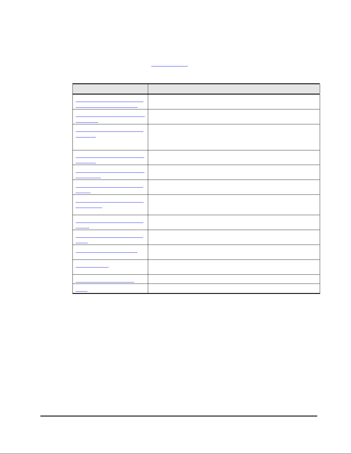
Document Organization
The following table provides an overview of the contents and organization of
this document. Click the chapter title
The first page of each chapter provides links to the sections in that chapter.
Chapter Description
in the left column to go to that chapter.
Chapter_1_Overview_of_Univers
al_Replicator_for_IBM_z/OS®
Chapter_2_About_Universal_Repl
icator_Ope
Chapter_3_Preparing_for_Univer
sal_Replic
Chapter_4_Using_the_Universal_
Replicator
Chapter_5_Configuring_Storage_
Systems_an
Chapter_6_Configuring_Journal_
Groups
Chapter_7_Using_Extended_Con
sistency_Gro
Chapter_8_Performing_Pair_Ope
rations
Chapter_9_Usage_Monitor_Oper
ations
Chapter_10_Usage_Scenarios
Troubleshooting
Acronyms and Abbreviations Defines the acronyms and abbreviations used in this document.
Index Lists the topics in this document in alphabetical order.
This chapter provides an overview of the Hitachi Universal Replicator software
and describes its features and benefits.
This chapter provides an overview of Universal Replicator operations.
This chapter describes URz operations involving the USP V primary and
secondary storage systems, the remote copy connections between the primary
\secondary storage systems, and the host(s) at the primary and secondary sites,
as well as the licensed URz remote console software
This chapter how to use the Universal Replicator for z/OS graphical user
interface.
This chapter how to use the Universal Replicator for z/OS graphical user
interface.
This chapter describes the introduction of the URz in your system and explains
how to configure your system for remote copy operations.
This chapter explains how to perform remote copy operations between more
than one primary and secondary storage system, as well as how to register
journal groups in extended consistency groups (abbreviated as EXCTG).
This chapter explains how to perform remote copy operations with UR z, including
how to create pairs of a primary data volume and a secondary data volume.
This chapter describes the Usage Monitoring window which enables you to collect
I/O statistics for all volumes to be monitored on the connected storage system.
This chapter describes how to use URz to enables to make Point-in-Time (PiT)
duplicates of groups of volumes.
This chapter provides troubleshooting information for Universal Replicator for
z/OS® and instructions for calling technical support.
Referenced Documents
Hitachi Universal Storage Platform V:
• LUN Manager User’s Guide, MK-96RD615
• User and Reference Guide, MK-96RD635
• Storage Navigator User’s Guide, MK-96RD621
• Business Continuity Manager User and Reference Guide, MK-94RD247
• Data Retention Utility User's Guide, MK-94RD210
• Virtual LVI/LUN and Volume Shredder User's Guide, MK-96RD630
Preface xiii
Hitachi Universal Replicator for IBM /OS User’s Guide
Page 14
• Universal Volume Manager User's Guide, MK-94RD626
• Guideline for the Timeout Menu Setting When Using At-Time Split Function
at Combining Universal Replicator with ShadowImage
• TrueCopy for IBM z/OS User's Guide, MK-94RD623
Document Conventions
The terms “Universal Storage Platform V” and “USP V” refer to all models of
the Hitachi Universal Storage Platform V, unless otherwise noted.
This document uses the following typographic conventions:
Typographic Convention Description
Bold
Italic
screen/code
< > angled brackets
[ ] square brackets
{ } braces
| vertical bar
underline Indicates the default value. Example: [ a | b ]
Indicates text on a window, other than the window title, including menus, menu
options, buttons, fields, and labels. Example: Click OK.
Indicates a variable, which is a placeholder for actual text provided by the user or
system. Example: copy source-file target-file
Note: Angled brackets (< >) are also used to indicate varia bles.
Indicates text that is displayed on screen or entered by the user. Example: #
pairdisplay -g oradb
Indicates a variable, which is a placeholder for actual text provided by the user or
system. Example:
Note: Italic font is also used to indicate variables.
Indicates optional values. Example: [ a | b ] indicates that you can choose a, b, or
nothing.
Indicates required or expected values. Example: { a | b } indicates that you must
choose either a or b.
Indicates that you have a choice between two or more options or arguments.
Examples:
[ a | b ] indicates that you can choose a, b, or nothing.
{ a | b } indicates that you must choose either a or b.
# pairdisplay -g <group>
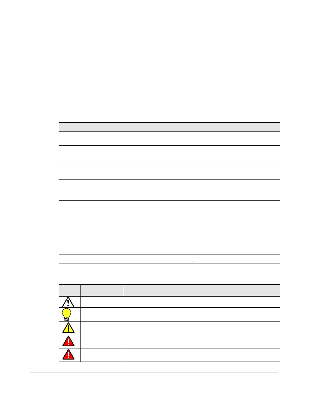
This document uses the following icons to draw attention to information:
Icon Meaning Description
Note Calls attention to important and/or additional information.
Tip
Caution
WARNING
DANGER
Provides helpful information, guidelines, or suggestions for performing tasks more
effectively.
Warns the user of adverse conditions and/or consequences (e.g., disruptive
operations).
Warns the user of severe conditions and/or consequences (e.g., destructive
operations).
Dangers provide information about how to avoid physical injury to yourself and
others.
xiv Preface
Hitachi Universal Replicator for IBM /OS User’s Guide
Page 15
ELECTRIC SHOCK
HAZARD!
ESD Sensitive
Warns the user of electric shock hazard. Failure to take appropriate precautions
(e.g., do not touch) could result in serious injury.
Warns the user that the hardware is sensitive to electrostatic discharge (ESD).
Failure to take appropriate precautions (e.g., grounded wriststrap) could result in
damage to the hardware.
Convention for Storage Capacity Values
Physical storage capacity values (e.g., disk drive capacity) are calculated
based on the following values:
1 KB = 1,000 bytes
1 MB = 1,000
1 GB = 1,000
1 TB = 1,000
1 PB = 1,000
Logical storage capacity values (e.g., logical device capacity) are calculated
based on the following values:
1 KB = 1,024 bytes
1 MB = 1,024
1 GB = 1,024
1 TB = 1,024
1 PB = 1,024
1 block = 512 bytes
Getting Help
If you need to call the Hitachi Data Systems Support Center, make sure to
provide as much information about the problem as possible, including:
• The circumstances surrounding the error or failure.
• The exact content of any error messages displayed on the host system(s).
2
bytes
3
bytes
4
bytes
5
bytes
2
bytes
3
bytes
4
bytes
5
bytes
• The exact content of any error messages displayed by Storage Navigator.
• The Storage Navigator configuration information (use the FD Dump Tool).
• The service information messages (SIMs), including reference codes and
severity levels, displayed by Storage Navigator.
The Hitachi Data Systems customer support staff is available 24 hours/day,
seven days a week. If you need technical support, please call:
• United States: (800) 446-0744
• Outside the United States: (858) 547-4526
Preface xv
Hitachi Universal Replicator for IBM /OS User’s Guide
Page 16

Comments
Please send us your comments on this document. Make sure to include the
document title, number, and revision. Please refer to specific section(s) and
paragraph(s) whenever possible.
• E-mail: doc.comments@hds.com
• Fax: 858-695-1186
• Mail:
Technical Writing, M/S 35-10
Hitachi Data Systems
10277 Scripps Ranch Blvd.
San Diego, CA 92131
Thank you! (All comments become the property of Hitachi Data Systems
Corporation.)
xvi Preface
Hitachi Universal Replicator for IBM /OS User’s Guide
Page 17

1
Overview of Universal Replicator for
®
IBM z/OS
This chapter provides an overview of the Hitachi Universal Replicator software
and describes its features and benefits. This chapter covers the following key
topics:
Hitachi Universal Replicator
Features
Benefits
Chapter 2 About Universal Replicator Operations 1-1
Hitachi Universal Replicator for IBM /OS User’s Guide
Page 18

Hitachi Universal Replicator
The Hitachi Universal Replicator software intelligently replicates data among
storage environments controlled through the Hitachi Universal Storage
Platform V, satisfying the most demanding disaster recovery and uptime
requirements. Since its introduction on the Hitachi TagmaStore
Storage Platform and Network Storage Controller, the Universal Replicator
software has set a new standard for data protection by redefining the way
asynchronous replication is performed.
Reliable data storage and recovery systems are essential in today’s market
climate where downtime can be very costly. Businesses must manage
increasing amounts of data across a variety of storage systems and operating
environments in various locations, while optimizing usage of storage hardware
resources and minimizing the management burden.
To address these needs, Hitachi Universal Replicator software provides the
enterprise-class performance associated with storage system-based replication
while delivering resilient business continuity. Through the Hitachi RAID storage
systems, Universal Replicator provides a powerful data management and
recovery solution that replicates data to a variety of storage platforms at one
or multiple remote sites. Data is replicated asynchronously over any distance
without the need for redundant servers or replication appliances, thus
significantly reducing resource consumption.
®
Universal
The Hitachi Universal Replicator software helps organizations to:
• Lower the cache and resource consumption on production/primary storage
systems
• Improve bandwidth utilization
• Simplify bandwidth planning
• Mitigate the impact of network failures
• Gain more flexibility in trading off between Recovery Point Objective and
cost
• Implement advanced multi–data center support more easily
• Move data among levels of tiered storage systems more easily
• Fully leverage the Universal Storage Platform V and optimize the storage
infrastructure
1-2 Chapter 3 Preparing for Universal Replicator z/OS Operations
Hitachi Universal Replicator for IBM /OS User’s Guide
Page 19

Features
Hitachi Universal Replicator provides the following key features:
• Heterogeneous Storage System Support
• More Efficient Replication
– Used with the Universal Storage Platform or Network Storage
Controller, Universal Replicator software enables storage management
and disaster recovery in heterogeneous systems, providing maximum
flexibility and support of enterprise-class environments.
– Universal Replicator software supports any storage connected to a
Universal Storage Platform or Network Storage Controller, permitting
data to be copied from any supported device to any other supported
device, regardless of operating system or protocol differences. This
ensures maximum flexibility for data distribution as well as increased
storage utilization and failover options.
– Universal Replicator software uses asynchronous replication driven by
the remote site to minimize impact on primary production systems and
takes advantage of journaling rather than cache files to mitigate the
high resource usage of other asynchronous approaches.
– Storage usage on the Universal Storage Platform or Network Storage
Controller can be minimal, just enough for the journals.
– Limited use of cache leaves cache for production application usage,
further restoring primary site storage to its intended role as a
transaction processing resource, not a replication engine.
– Advanced three data center capabilities provide a choice of cascade or
multi-target configurations (teams with TrueCopy Synchronous software
for advanced configurations).
– Consistency groups can span multiple storage systems for large
enterprise-class applications requiring unmatched scalability and data
integrity.
Note: Please check with your Hitachi Data Systems representative for detailed
feature availability information.
Chapter 2 About Universal Replicator Operations 1-3
Hitachi Universal Replicator for IBM /OS User’s Guide
Page 20

Benefits
The business benefits of Hitachi Universal Replicator include:
• Ensure Business Continuity
– Simplifies implementation to meet the most demanding disaster
recovery and uptime requirements, regardless of the type of supported
storage platform hosting the business-critical data
– Supports availability of up-to-date copies of data in dispersed locations
by leveraging Hitachi TrueCopy
®
Synchronous software
– Maintains integrity of a replicated copy without impacting processing,
even when replication network outages occur or optimal bandwidth is
not available
– Works with Universal Storage Platform V replication technology to
greatly enhance administrative productivity and response to and
proactive aversion of crises
• Optimize Resource Usage
– Leverages advanced technology to maintain data integrity and optimize
the storage/IT infrastructure for protection of data from any application
across a variety of hardware and software platforms
– Optimizes storage resources for more efficient data protection over any
distance
– Significantly reduces cache utilization and increases bandwidth
utilization by leveraging performance-optimized disk-based journals
– Reduces overhead and application impact at production site by placing
more of the workload on remote site
– Centralizes operations for management resources and provides secure
management of data-related operational risk
• Improve Operational Efficiency and Resiliency
– Simplifies consolidation/aggregation and mapping of data value to the
cost of storage
– Supports planned site outages
– Keeps logging changes in the event of network problems between sites
– Reduces costs—requires only one product to provide asynchronous copy
across all attached storage systems
• Synergy with Hitachi Business Continuity Framework
– Builds on the data integrity heritage of Hitachi open-systems and
mainframe remote replication software
– Provides unified, simplified management via Hitachi HiCommand®
Device Manager and Hitachi Business Continuity Manager software for
IBM® z/OS®
1-4 Chapter 3 Preparing for Universal Replicator z/OS Operations
Hitachi Universal Replicator for IBM /OS User’s Guide
Page 21

– Integrates tightly with other Hitachi software products supporting
business continuity, further expanding capabilities
Business Solutions
Hitachi Data Systems and its Hitachi TrueNorth™ Channel Partners provide
cost-effective storage products and solutions that leverage world-renowned
Hitachi global R&D resources to deliver performance, availability, and
scalability—supporting business-critical applications and strengthening
competitive advantage.
Complementary solutions for Universal Replicator software include:
• Hitachi HiCommand
• Hitachi TrueCopy
like Hitachi storage systems
• Hitachi ShadowImage™ Heterogeneous In-System Replication software for
non-disruptive, high-speed data replication within any Hitachi storage
system
®
Replication Monitor software
®
Synchronous software, which duplicates data between
Hitachi Business Continuity Manager software for managing TrueCopy and
ShadowImage solutions for IBM
®
z/OS® mainframe
Chapter 2 About Universal Replicator Operations 1-5
Hitachi Universal Replicator for IBM /OS User’s Guide
Page 22

1-6 Chapter 3 Preparing for Universal Replicator z/OS Operations
Hitachi Universal Replicator for IBM /OS User’s Guide
Page 23

2
About Universal Replicator Operations
This chapter provides an overview of Universal Replicator operations:
Functionality Overview
Components
Remote Copy Operations
Journal Processing
URz Delta Resync Operation
Pair Status
Business Continuity Manager Support
Chapter 3 Preparing for Universal Replicator z/OS Operations 2-1
Hitachi Universal Replicator for z/OS User’s Guide
Page 24

Functionality Overview
Hitachi Universal Replicator represents a unique and outstanding disaster
recovery solution for large amounts of data that span multiple volumes. The
UR group-based update sequence consistency solution enables fast and
accurate database recovery, even after a “rolling” disaster, without the need
for time-consuming data recovery procedures. The user-defined UR journal
groups (volume groups) at the secondary site can be recovered with full
update sequence consistency but behind the primary site due to asynchronous
copy operations. This functionality also provides protection for writedependent applications in the event of a disaster.
UR enables you to create duplicate volumes by copying data from the primary
data volumes in the primary storage system to the secondary data volumes in
the secondary storage system at the remote location. To perform this function,
the journal obtain function at the primary site, the journal copy function
between the primary and secondary sites, and the journal restore function at
the secondary site are performed sequentially with the primary and secondary
data volumes and the journal volumes. Write sequence consistency for the
primary data volume at the primary site is also maintained for the secondary
data volume at the secondary site by the write sequence number to be
assigned for the journal data with the journal obtaining function, enabling you
to configure the duplicate system which has data integrity. UR reduces the
occurrence of pair suspensions due to restrictions of data transfer from the
primary site to the secondary site by storing the write data from the host in
the master and restore journal volumes, providing a high-reliability duplication
system.
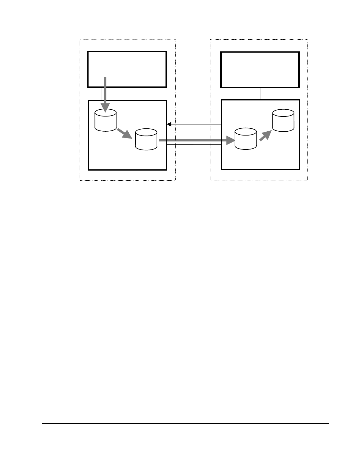
Figure 2-1 UR Components for Fibre-Channel Connection shows an overview of
UR operations.
2-2 Chapter 3 Preparing for Universal Replicator z/OS Operations
Hitachi Universal Replicator for IBM /OS User’s Guide
Page 25
y
y
j
j
Primary site
Secondar
site
Primary
data
volume
Journal obtain
function
Figure 2-1 UR Components for Fibre-Channel Connection
Journal Obtain
Journal obtain is the function to store the already stored data in the primary
data volume as a base-journal in the journal volume at the primary site. And
then, this function stores the write data as a journal data in the journal
volume with every update of the primary data volume according to the write
instruction from the host. The journal obtain operation is performed according
to the instruction of add pair or Resume Pair operation from the primary site.
The write sequence number from the host is assigned to the journal data.
According to this information, the write sequence consistency at the secondary
site can be maintained. The update data from the host is kept in the cache.
Therefore, the journal obtain function for the update data is performed
asynchronously from the time the storage system receives the update data
from the host and stores the update data to the data volume.
Primary host
Write instruction
Issuing Read
Journal command
Secondary host
Master
ournal
Primar
volume
storage system Secondary storage system
Journal copy function
Restore
ournal
volume
Secondary
data
volume
Journal restore
function
Chapter 2 About Universal Replicator Operations 2-3
Hitachi Universal Replicator for IBM /OS User’s Guide
Page 26

Journal Copy
Journal copy is the function to copy the data in the master journal volume at
the primary site to the restore journal volume at the secondary site. The
secondary storage system issues the read journal command to the primary
storage system to request to transfer the data that is stored in the master
journal volume according to the pair create or Resume Pair operation
instruction from the primary site. The primary storage system transfers the
data in the journal volume to the secondary site according to the read journal
command if it has the journal data that should be sent. If the primary storage
system does not have the journal data, the information is sent. The secondary
storage system stores the journal volume data that is sent from the primary
site in the restore journal volume at the secondary site. The read journal
commands are issued repeatedly and regularly from the secondary site to the
primary site until the journal operation is stopped. After the data are restored,
the journal sequence numbers are informed from the secondary site to the
primary site when the read journal command is issued. According to this
information, the journal data at the primary site are discarded.
Journal Restore
Journal restore is the function to reflect the stored data in the restore journal
volume to the secondary data volume at the secondary site. The data in the
restore journal volume are restored to the secondary data volume according to
the write sequence number. This will ensure the write sequence consistency
between the primary and secondary data volumes. After the journal data are
restored to the secondary data volume, the journal data are discarded at the
secondary site.
Components
URz operations involve the USP V storage systems at the primary and
secondary sites, the physical communications paths between these storage
systems, and the USP V URz remote console software. URz copies the original
online data at the primary site to the offline backup volumes at the secondary
site via the dedicated fibre-channel remote copy connections using a journal
volume. You can operate the URz software with the user-friendly GUI
environment using the USP V URz remote console software.
Note: Host failover software is required for effective disaster recovery with URz.
For management of URz journal groups that consist of journal volumes located
in multiple storage systems, host I/O time stamping function (provided by
MVS DFSMSdfp) is a requisite functional item. An error reporting
communications (ERC) feature is essential for URz to be able to recover data
lost in a disaster.
Figure 2-2 shows the URz components and their functions:
2-4 Chapter 3 Preparing for Universal Replicator z/OS Operations
Hitachi Universal Replicator for IBM /OS User’s Guide
Page 27
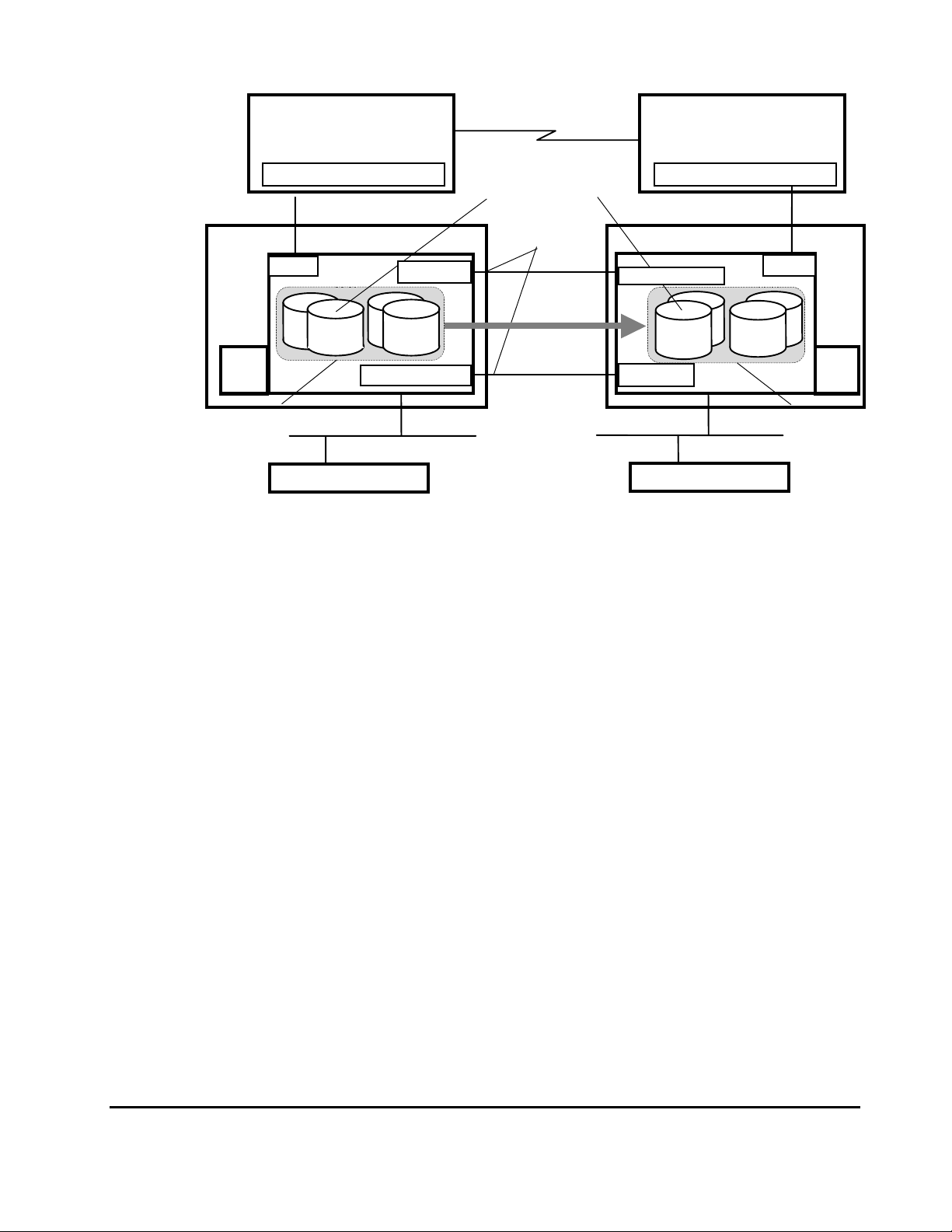
y
)
g
)
g
y
(
Host processor
at the primary site
MVS) Time stamping function (MVS) Time stamping function
Error Reporting
Communications
URz volume pair
Host processor
at the secondary site
Disk subsystemStorage system
e system (LDKC
et port
Secondar
L
data
volume
CHT
RCU
Restore
journal
volume
SVP
Restore journal group
Primar
CHT
Primary
data
volume
SVP
Master journal group
Storage Navigator computer
subsystem(LDKC
MCU
Internal LAN (TCP/IP)
Initiator port
Master
journal
volume
RCU target port
Remote copy
connection
Copy direction
Stora
RCU tar
Initiator port
Storage Navigator computer
Figure 2-2 URz components
Figure 2-3 shows the plural secondary storage systems connection
configuration of URz. By connecting one primary storage system with more
than one secondary storage system, you can create a volume pair that has a
one-to-one relationship for each journal group.
Chapter 2 About Universal Replicator Operations 2-5
Hitachi Universal Replicator for IBM /OS User’s Guide
Page 28
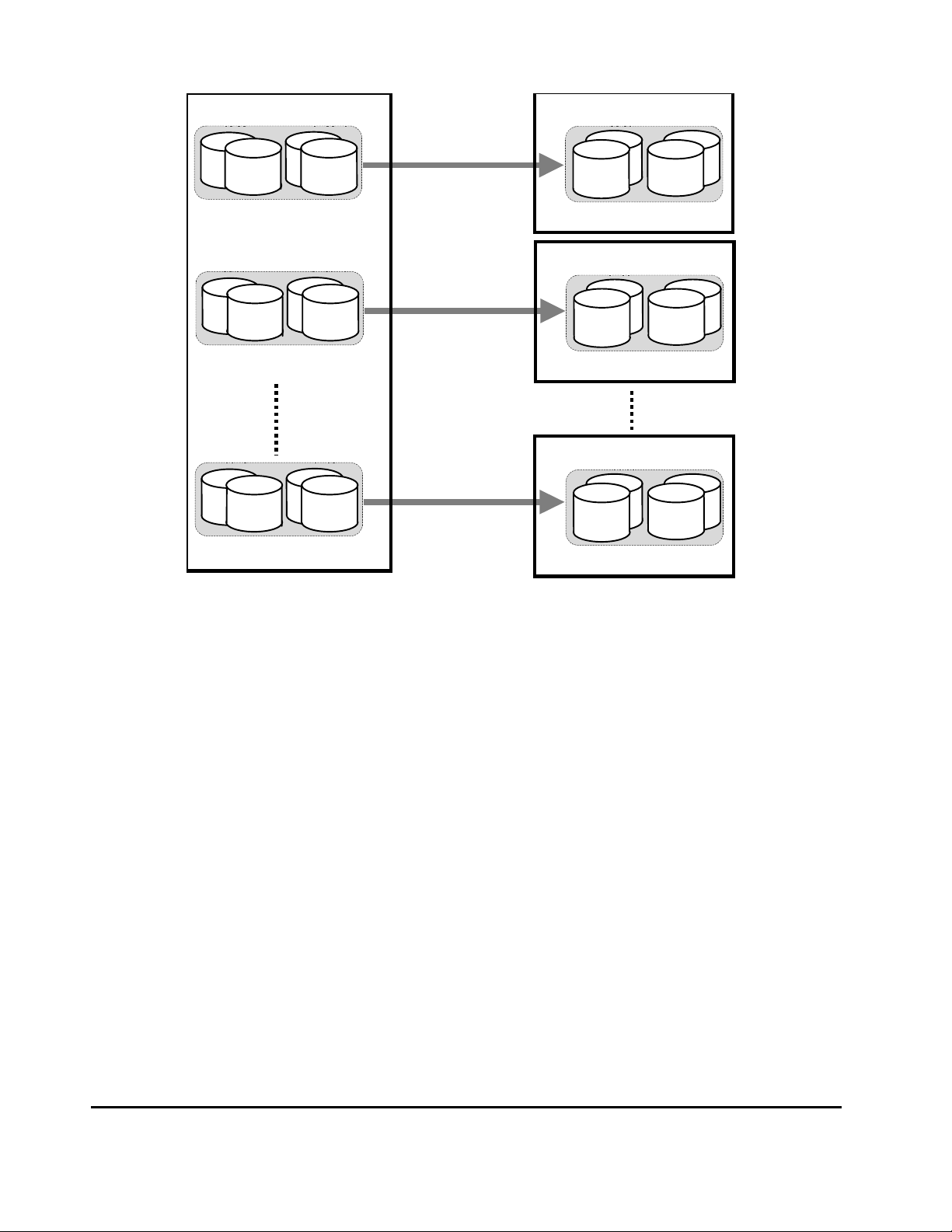
Primary storage system
Secondary storage system
Primary
data
volume
Master journal group 0
Primary
data
volume
Master journal group 1
Primary
data
volume
Master journal group n
Master
journal
volume
Master
journal
volume
Master
journal
volume
Secondary
data
volume
Restore
journal
volume
Restore
journal
volume
Secondary storage system
Secondary
data
volume
Restore
journal
volume
Secondarystorage system
Secondary
data
volume
Figure 2-3 Connection Confi guration of Plural Secondary Storage
systems
This URz components describes:
• USP V storage system
• Logical DKC
• Main and remote control units (primary storage systems and secondary
storage systems)
• Journal group
• Data volume pair
• Journal volume
• Remote copy connections
• Initiator ports and RCU target ports
• USP V URz remote console software
• Host I/O time stamping function
• Error reporting communications (ERC)
2-6 Chapter 3 Preparing for Universal Replicator z/OS Operations
Hitachi Universal Replicator for IBM /OS User’s Guide
Page 29

USP V Storage Systems
URz operations involve the USP V storage systems at the primary and
secondary sites. The primary storage system consists of the main control unit
(primary storage system) and SVP. The secondary storage system consists of
the remote control unit (secondary storage system) and SVP.
To provide greater flexibility and to enable the USP V to be tailored to unique
customer operating requirements, operational parameters, or optional modes,
are available in URz for the USP V storage system. At installation, the USP V
modes are set to their default values, so make sure to discuss these settings
with your Hitachi team. The USP V modes can only be changed by your Hitachi
representative.
Universal Replicator for z/OS® Software
USP V Storage Navigator Java applet program product includes URz for the
USP V storage system. The USP V Storage Navigator software communicates
with the SVP of each USP V storage system via defined TCP/IP connections.
For further information on USP V Storage Navigator operations, please refer to
the Storage Navigator User's Guide, or contact your Hitachi account team.
The Storage Navigator PC at the primary site must be attached to the primary
storage system. You should also attach a Storage Navigator PC at the
secondary site to all secondary storage systems. Having a Storage Navigator
PC at the secondary site enables you to change the URz parameter of the
secondary storage system and access the URz secondary data volume (e.g. for
the maintenance of media). If you need to perform URz operations in the
reverse direction from the secondary site to the primary site (e.g., disaster
recovery), the USP V URz software simplifies and expedites this process.
Note: If the USP V Storage Navigator remote console PC is not installed, please
contact your Hitachi account team for information on URz configuration
services.
Main and Remote Control Units
The main control unit (primary storage system) and remote control unit
(secondary storage system) control URz operations:
Chapter 2 About Universal Replicator Operations 2-7
Hitachi Universal Replicator for IBM /OS User’s Guide
Page 30

• The primary storage system is the control unit in the primary storage
system which controls the primary data volume of the URz pairs and
master journal volume. The Storage Navigator remote console PC must be
LAN-attached to the primary storage system. The primary storage system
communicates with the secondary storage system via the dedicated remote
copy connections. The primary storage system controls the host I/O
operations to the URz primary data volume and the journal obtain
operation of the master journal volume as well as the URz initial copy and
update copy operations between the primary data volumes and the
secondary data volumes.
• The secondary storage system is the control unit in the secondary storage
system which controls the secondary data volume of the URz pairs and
restore journal volume. The secondary storage system controls copying of
journals and restoring of journals to secondary data volumes. The
secondary storage system assists in managing the URz pair status and
configuration (e.g., rejects write I/Os to the URz secondary data volumes).
The secondary storage system issues the read journal command to the
primary storage system and executes copying of journals. The secondary
Storage Navigator PC should be connected to the secondary storage
systems at the secondary site on a separate LAN. The secondary storage
systems should also be attached to a host system to allow sense
information to be reported in case of a problem with a secondary data
volume or secondary storage system and to provide disaster recovery
capabilities.
The USP V can function simultaneously as a primary storage system for one or
more primary data volumes and as a secondary storage system for one or
more secondary data volumes, provided the remote copy connections and
fibre-channel interface ports are properly configured. The URz software allows
you to specify the secondary storage system from the connected primary
storage system. URz operations can be performed on all LDEVs except for the
USP V command device. For further information on the USP V command
device, please refer to the Business Continuity Manager User and Reference
Guide.
Note: When you configure a URz journal group pair, you have to specify the
serial numbers of primary storage systems and secondary storage systems.
You have to specify the different serial numbers of primary storage system
and secondary storage system for the same URz journal group pair. If you
have to specify the same serial number, please contact your Hitachi account
team.
Logical DKC (LDKC)
The USP V storage system controls the CU (Control Unit) by dividing the CUs
in to groups of 255 CUs. Each group is a storage system that logically exists in
USP V (logical storage system). These groups are called a “logical DKC” or an
“LDKC (L
system and number “00” and “01” is assigned to each LDKC.
2-8 Chapter 3 Preparing for Universal Replicator z/OS Operations
ogical disk controller)”. There are 2 LDKCs in the USP V storage
Hitachi Universal Replicator for IBM /OS User’s Guide
Page 31

Each LDKC controls 255 CUs, however the number of CUs that can be used for
USP V program products is up to 255. Therefore, the maximum number of
volumes that can be used for USP V program products is 130,560 (65,280
volumes for an LDKC).
Remote Copy Connections
The remote copy connections are the physical paths used by the primary
storage systems to communicate with the secondary storage systems. Remote
copy connections enable communication between the primary and secondary
storage systems. The primary storage systems and secondary storage systems
are connected via fibre-channel interface cables. You must establish paths
from the primary to the secondary storage system, and also from the
secondary to the primary storage system. Up to eight paths can be established
in both of these directions.
When fibre-channel interface (optical multimode shortwave) connections are
used, two switches are required for distances greater than 0.5 km (1,640
feet), and distances up to 1.5 km (4,920 feet, 0.93 miles) are supported. If
the distance between the primary and secondary sites is greater than 1.5 km,
the optical single mode long wave interface connections are required. When
fibre-channel interface (single-mode long wave) connections are used, two
switches are required for distances greater than 10 km (6.2 miles), and
distances up to 30 km (18.6 miles) are supported.
See section
Setting up Remote Copy Connections for further information on
installing and configuring the FC remote copy connections.
The URz remote copy configuration between primary storage system and
secondary storage system has the following requirements:
URz supports 1-to-1 remote copy connection in one journal group pair. In
one journal group pair, one primary storage system can be connected to
only one secondary storage system. This configuration ensures the backup
data consistency of two or more volumes (e.g., large databases) within the
same storage system.
Note: Hitachi strongly recommends that you establish at least two independent
remote copy connections from the primary storage system to the secondary
storage system and vice versa to provide hardware redundancy for this critical
communications path.
Chapter 2 About Universal Replicator Operations 2-9
Hitachi Universal Replicator for IBM /OS User’s Guide
Page 32

Initiator Ports and RCU Target Ports
The initiator port and the RCU target port are required at both the primary
storage system and secondary storage system. The initiator port at the
primary storage system is connected to the RCU target port at the secondary
storage system via the fibre channel interface. The initiator port at the
secondary storage system is connected to the RCU target port at the primary
storage system. The initiator port at the secondary storage system issues a
"read journal" command to the primary storage system, and then the RCU
target port at the primary storage system sends journal data to the secondary
storage system in response to the "read journal" command.
Any fibre-channel interface port of the USP V can be configured as an initiator
port. The initiator ports cannot communicate with the host processor channels.
The host channel paths must be connected to the fibre-channel interface port
other than the initiator port.
Note: Two or more initiator ports must be configured before you can add the
secondary storage systems and create the URz volume pairs.
The fibre-channel interface ports that are assigned for the RCU target ports
can be connected to the host channel paths via the fibre-channel switch.
See section
interface port.
Data Volume Pair
URz performs remote copy operations for data volume pairs created by the
user. Each URz pair consists of one primary data volume and one secondary
data volume which can be located in different storage systems. The URz
primary data volumes are the primary volumes (LDEVs) which contain the
original data, and the URz secondary data volumes are the secondary volumes
(LDEVs) which contain the backup or duplicate data. During normal URz
operations, the primary data volume remains available to all hosts at all times
for read and write I/O operations. During normal URz operations, the
secondary storage system rejects all host-requested write I/Os for the
secondary data volume. The secondary data volume write enable option allows
write access to a secondary data volume while the pair is split and uses the
secondary data volume and primary data volume track maps to resynchronize
the pair (see section
URz also supports the Virtual LVI/LUN (VLL) and Cache Residency Manager
features, so that URz meets a variety of user needs and facilitates data
copying and data migration. This ensures that all user data can be backed up
or duplicated. See section
further information on LU requirements and support.
Configuring Port Attributes for the information on configuring host
Secondary Data Volume Write Option).
Duplicate VOLSER (Volume Serial Number) for
2-10 Chapter 3 Preparing for Universal Replicator z/OS Operations
Hitachi Universal Replicator for IBM /OS User’s Guide
Page 33

Journal Volume
When URz is used, updates to primary data volumes can be stored in other
volumes, which are called journal volumes. The updates (which are sometimes
referred to as update data) that will be stored in journal volumes are called
journal data.
Because journal data will be stored in journal volumes, you can perform and
manage highly reliable remote copy operations without suspension of remote
copy operations. For example:
Even if a communication path between the primary storage system and the
secondary storage system fails temporarily, remote copy operations can
continue after the communication path is recovered.
If data transfer from hosts to the primary storage system is temporarily faster
than data transfer between the primary storage system and the secondary
storage system, remote copy operations between the primary storage system
and the secondary storage system can continue. Because journal volumes can
contain a lot more update data than the cache memory can contain, remote
copy operations can continue if data transfer from hosts to the primary
storage system is faster for a relatively long period of time than data transfer
between the primary storage system and the secondary storage system.
The Number of Journal Volumes
One journal group can contain up to 64 journal volumes. Each of the journal
volumes can have different volume sizes and different RAID configurations.
Journal data will be stored sequentially and separately into each journal
volume in the same journal group.
Specifications of Journal Volumes
Types of logical units (LUs):
The following DKU emulation types are allowed for journal volumes:
Table 2-1 Emulation Types for Journal Volumes
Emulation Category Supported Emulation Types
DKU (drive)
Volumes and their capacity:
You can use VLL volumes for journal volumes.
Journal volumes in the same journal group can be of different capacity. A
master journal volume and the corresponding restore journal volume can
be of different capacity.
OPEN-V
All mainframe volumes that can be used with USP V
Note: Status of mainframe volumes cannot be referenced.
Chapter 2 About Universal Replicator Operations 2-11
Hitachi Universal Replicator for IBM /OS User’s Guide
Page 34

A journal volume consists of two areas: one area is used for storing journal
data, and the other area is used for storing metadata for remote copy.
RAID configuration:
Journal volumes support all RAID configurations that are supported by
USP V. Journal volumes also support all physical volumes that are
supported by USP V.
Support for program products:
The volumes on which Cache Residency Manager settings are made can be
used for journal volumes.
Caution: Volumes containing a VMA (volume management area) cannot be used
as journal volumes. For detailed information about a VMA, please refer to the
Data Retention Utility User's Guide.
Restrictions on Journal Volumes
Registering journal volumes:
Caution: You must register journal volumes in a journal group before you
create a data volume pair for the first time in the journal group.
You can add journal volumes under any of the following conditions:
– When the journal group does not contain data volumes (i.e., before you
create a data volume pair for the first time in the journal group, or after
all data volume pairs are released)
– When all data volume pairs in the journal group are suspended.
– When processing for changing the status of a data volume pair (for
example, release or suspension of a data volume pair) is not in progress
Note: If a path is defined from a host to a volume, you cannot register the
volume as a journal volume.
You can use Storage Navigator computers to register journal volumes.
If you add a journal volume when a remote copy operation is in progress
(i.e., when at least one data volume pair exists for data copying), the
metadata area of the journal volume (see the next section) will be unused
and only the journal data area will be used. To make the metadata area
usable, you need to split (suspend) all the data volume pairs in the journal
group and then restore (resynchronize) the pairs.
Adding journal volumes during a remote copy operation will not decrease
the metadata usage rate if the metadata usage rate is high.
Adding journal volumes during a remote copy operation may not change
the journal data usage rate until the journal volumes are used. To check
the journal data usage rate, use the Usage Monitor window (see
Usage
Monitor Window).
2-12 Chapter 3 Preparing for Universal Replicator z/OS Operations
Hitachi Universal Replicator for IBM /OS User’s Guide
Page 35

Deleting journal volumes:
You can delete journal volumes under any of the following conditions:
– When the journal group does not contain data volumes (i.e., before you
create a data volume pair for the first time in the journal group, or after
all data volume pairs are released)
– When all data volume pairs in the journal group are suspended.
You can use Storage Navigator computers to delete journal volumes.
Caution:
– If you delete a mainframe journal volume from a journal group where a
data volume pair has ever been registered, the deleted volume (LDEV)
will be blocked. If you want to reuse the volume as a data volume, you
must format the volume by using Virtual LVI/LUN (VLL). Unless you
format the volume, data in the volume will not be guaranteed.
For instructions on formatting volumes, please refer to the Virtual LVI/LUN
and Volume Shredder User's Guide. Note that you do not need to format
the volume if you want to register the deleted volume as a journal volume
again.
Access from hosts to journal volumes:
If a path is defined from a host to a volume, you cannot register the
volume as a journal volume.
You cannot define paths from hosts to journal volumes. This means that
hosts cannot read from and write to journal volumes.
Journal Volume Areas
The journal volume consists of the metadata area and the journal data area.
The ratio of metadata area to journal data area is common in the journal
volumes within the journal group.
In the metadata area, the metadata that manages the journal data is stored.
For further information on the metadata area, see
that the metadata manages is stored in the journal data area.
Note: If the metadata or the journal data cannot be stored for a given length of
time because the metadata or journal data areas have become full with the
metadata or the journal data that had not been discarded, the pair is
suspended according to a failure. Users can use a Storage Navigator computer
to specify this timeout period (Data overflow watch) as a journal group option.
This timeout period must be within the range of 0 to 600 seconds. For details
on journal group options, see section
Table 2-3. The journal data
Changing Options for a Journal Group.
Journal Group
Chapter 2 About Universal Replicator Operations 2-13
Hitachi Universal Replicator for IBM /OS User’s Guide
Page 36

Journal group consists of two or more data volumes and journal volumes. It is
a feature that allows you to sort multiple data volumes and journal volumes
into collective units to tailor URz to meet your unique business needs. The
journal group in the primary storage system is referred to as the master
journal group. The journal group in the secondary storage system is referred
to as the restore journal group. The data volumes in the master journal group
are also called the primary data volumes. The journal volumes in the master
journal group are called the master journal volumes. The data volumes in the
restore journal group are similarly called the secondary data volumes. The
journal volumes in the restore journal group are called the restore journal
volumes.
The data update sequence from the host is managed per the journal group.
The data update sequence consistency between the master and restore journal
groups to be paired is maintained and ensured. The master and restore journal
groups are managed according to the journal group number. The journal
numbers of master and restore journal groups that are paired can be different.
One data volume and one journal volume can belong to only one journal
group.
Caution: Data volumes and journal volumes that belong to different LDKCs
cannot coexist in the same journal group.
For detailed information about the specification of journal groups, see
3-9.
Extended Consistency Groups
To perform remote copy operations between more than one primary storage
system and more than one secondary storage systems while maintaining data
consistency, you must register journal groups in an extended consistency
group (abbreviated as EXCTG). An extended consistency group is a collection
of journal groups. This manual uses the term "primary EXCTG" to refer to an
extended consistency group for primary storage systems. This manual also
uses the term "secondary EXCTG" to refer to an extended consistency group
for secondary storage systems.
To perform remote copy operations between more than one primary storage
system and more than one secondary storage systems while maintaining data
consistency, you must configure a secondary EXCTG. Also, it is recommended
that you configure a primary EXCTG, because the primary EXCTG will be
necessary if you need to reverse the primary and secondary sites after a
failure occurs. You can register journal groups of up to four different storage
systems in the same extended consistency group, but you cannot register one
journal group in different extended consistency groups. The following table
explains specifications of extended consistency groups:
Table
2-14 Chapter 3 Preparing for Universal Replicator z/OS Operations
Hitachi Universal Replicator for IBM /OS User’s Guide
Page 37

Table 2-2 Specifications of Extended Consistency Groups
Item Specifications
The number of extended consistency groups that can be created Up to four per one storage system
The number of journal groups that can be registered in one
extended consistency group
Up to 16
The following explains configuration of extended consistency groups (i.e.,
primary and secondary EXCTGs). Note the following when configuring
extended consistency groups.
Guaranteed Consistency of Data Update Sequence:
URz restores journal data to secondary data volumes by taking the
following steps. The following procedure guarantees consistency of data
update sequence within an extended consistency group:
a. URz checks the extended consistency group for the time stamps of all
journal data that have not been restored to secondary data volumes,
and then identifies the latest time stamp for each journal group.
In the example shown in
Figure 2-4, the latest time stamp for each
journal group is as follows:
• In Journal group 1, the latest time stamp is 15:00.
• In Journal group 2, the latest time stamp is 15:02.
• In Journal group 3, the latest time stamp is 15:03.
• In Journal group 4, the latest time stamp is 15:04.
b. URz searches for the oldest time stamp from the ones identified in step
a and restores data up to that time to the secondary volumes.
In the example shown in
Figure 2-4, the oldest time stamp is 15:00.
URz restores all data that have a time stamp 15:00 or earlier to the
secondary data volumes.
• For Journal group 1, URz restores all data up to 15:00.
• For Journal group 2, URz restores all data up to 14:02.
• For Journal group 3, URz restores all data up to 14:03.
• For Journal group 4, URz restores all data up to 14:04.
Chapter 2 About Universal Replicator Operations 2-15
Hitachi Universal Replicator for IBM /OS User’s Guide
Page 38
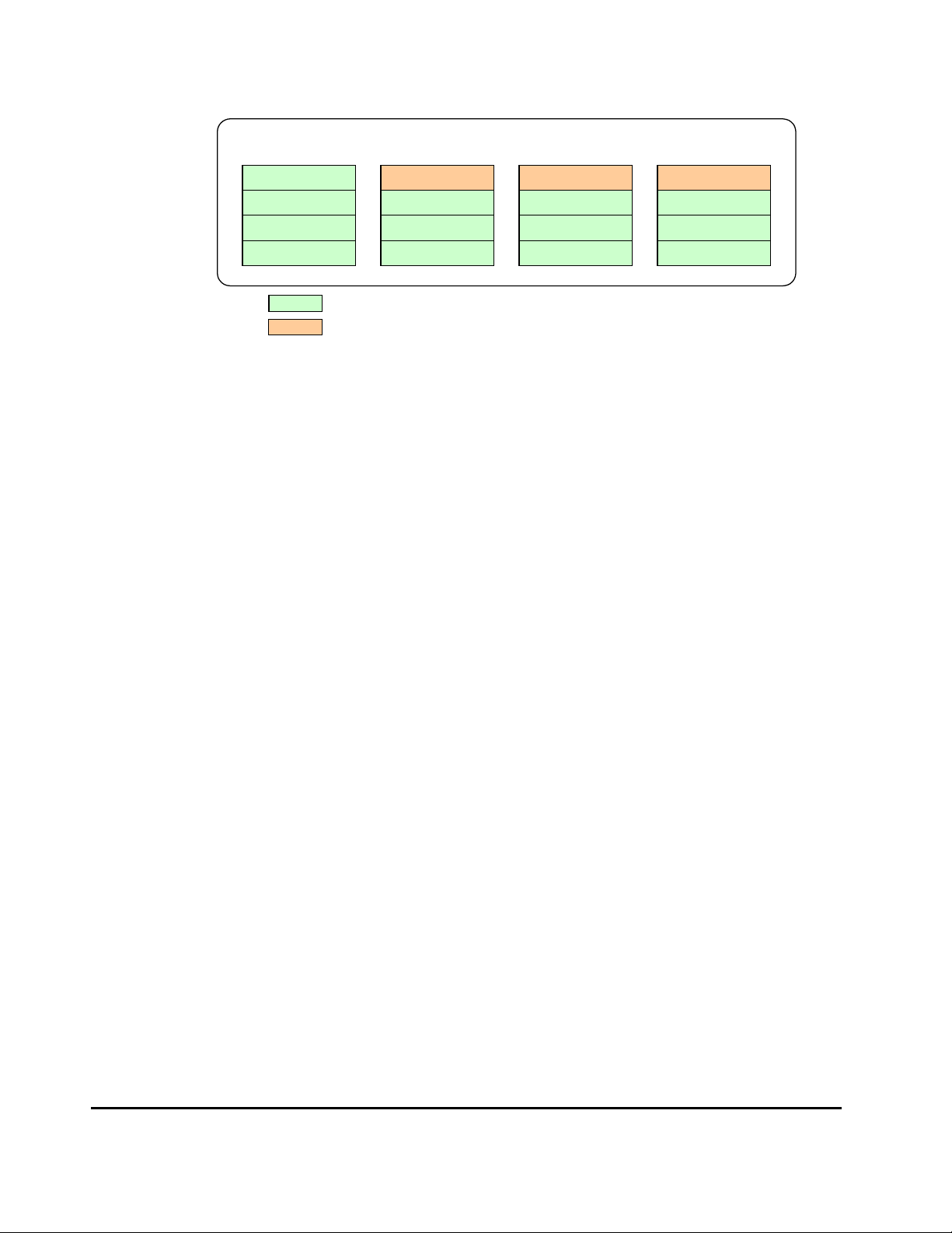
Extended consistency group
Journal group 1
15:00
14:00
13:00
12:00
Legend:
Figure 2-4 Time Stamps of Data that Have Not Been Restored to
Consistency time:
In the URz windows, consistency times of extended consistency groups,
journal groups, and data volume pairs are displayed. These consistency
times have the following meanings.
– The consistency time of an extended consistency group is the latest
time stamp of the restored data in the group in which consistency is
guaranteed.
In the example shown in
extended consistency group is 15:00.
Journal group 2
15:02
14:02
13:02
12:02
indicates data that is to be restored to secondary data volumes
indicates data that is not to be restored to secondary data volumes
Journal group 3
15:03
14:03
13:03
12:03
Journal group 4
Secondary Data Volumes
Figure 2-4, the consistency time of the
15:04
14:04
13:04
12:04
– The consistency time of a journal group is the latest time stamp of the
restored data.
In the example shown in
Figure 2-4, the consistency times of journal
groups 1 to 4 are as follows.
• The consistency time of Journal group 1 is 15:00.
• The consistency time of Journal group 2 is 14:02.
• The consistency time of Journal group 3 is 14:03.
• The consistency time of Journal group 4 is 14:04.
– The consistency time of a data volume pair is the latest time stamp of
the data that has been restored when the pair becomes suspended.
In the example shown in
Figure 2-4, if a pair in the journal group 1, 2,
3 or 4 is suspended immediately after data are restored, the
consistency time of the pair will be as follows.
• If a pair in Journal group 1 is suspended, the consistency time will
be 15:00.
• If a pair in Journal group 2 is suspended, the consistency time will
be 14:02.
• If a pair in Journal group 3 is suspended, the consistency time will
be 14:03.
2-16 Chapter 3 Preparing for Universal Replicator z/OS Operations
Hitachi Universal Replicator for IBM /OS User’s Guide
Page 39

• If a pair in Journal group 4 is suspended, the consistency time will
be 14:04.
If a failure occurs in a primary storage system and then you wish to
recover from the failure, please restore journal data with time stamps later
than the consistency time of the extended consistency group to secondary
data volumes. For example, in the case described in
Figure 2-4, the
consistency time of the extended consistency group is 15:00, and therefore
you must restore the following data to secondary data volumes.
• Data with the time stamp 15:02 in journal group 2
• Data with the time stamp 15:03 in journal group 3
• Data with the time stamp 15:04 in journal group 4
If a failure occurs in a secondary storage system and then you wish to
recover from the failure, please compare the consistency times of all
journal groups in the extended consistency group, and then identify the
oldest consistency time. Next, please restore all data with time stamps
later than the oldest consistency time, to the secondary data volume. For
example, in the case described in
Figure 2-4, the consistency time of
journal group 2 is the oldest among journal groups 1 to 4. Since the
consistency time of journal group 2 is 14:02, you must restore the
following data to secondary data volumes.
• Data with the time stamp 15:00 in journal group 1
• Data with the time stamp 15:02 in journal group 2
• Data with the time stamp 14:03, and data with the time stamp
15:03 in journal group 3
• Data with the time stamp 14:04, and data with the time stamp
15:04 in journal group 4
Host I/O Time-Stamp
If you plan to establish URz journal groups, the I/O time-stamping function
must be installed on the host processor at the primary site. The I/O timestamp, which is provided by MVS DFSMSdfp, is the same time-stamp that is
used by Compatible XRC pairs. The I/O time-stamping function should also be
installed on the host processor at the secondary site, so that time-stamps can
be used when copying data in the reverse direction.
Note: If the system at the primary and/or secondary site consists of several
CPU complexes, a SYSPLEX timer is required to provide a common time
reference for the I/O time-stamping function.
Chapter 2 About Universal Replicator Operations 2-17
Hitachi Universal Replicator for IBM /OS User’s Guide
Page 40

Error Reporting Communications (ERC)
y
Error reporting communications (ERC), which transfers information between
host processors at the primary and secondary sites, is a critical component of
any disaster recovery effort. You can configure ERC using channel-to-channel
communications, NetView technology, or other interconnect technologies,
depending on your installation requirements and standards. Neither URz nor
the URz remote console software provides ERC between the primary and
secondary sites.
When URz is used as a data migration tool, ERC is recommended but is not
required. When URz is used as a disaster recovery tool, ERC is required to
ensure effective disaster recovery operations. When a URz pair is suspended
due to an error condition, the primary storage system generates sense
information which results in an IEA491E system console message. This
information should be transferred to the primary site via the ERC for effective
disaster detection and recovery.
Remote Copy Operations
Figure 2-5 illustrates the two types of URz remote copy operations: initial copy
and update copy.
Primary host
Write instruction
Obtaining updated
journal data
Master
journal
volume
Obtaining base-journal
Primary storage system
Primary
data
volume
Secondar
Restore
Update copy
Restore
Initial copy
journal
volume
Secondary storage system
host
Secondary
data
volume
Figure 2-5 Remote copy operations
This section describes the following topics that are related to remote copy
operations with URz:
• Initial copy operation (see the next section)
2-18 Chapter 3 Preparing for Universal Replicator z/OS Operations
Hitachi Universal Replicator for IBM /OS User’s Guide
Page 41

• Update copy operation
• Read and write I/O operations for URz volumes
• Secondary data volume write option
• Secondary data volume read option
• Difference management
Initial Copy Operations
Initial copy operations synchronize data in the primary data volume and data
in the secondary data volume. Initial copy operations are performed
independently from host I/Os. Initial copy operations are performed when you
create a data volume pair or when you resynchronize a suspended pair. The
initial copy operation copies the base-journal data that is obtained from the
primary data volume at the primary storage system to the secondary storage
system, and then restores the base-journal to the secondary data volume.
If the journal-obtain operation starts at the primary data volume, the primary
storage system obtains all data of the primary data volume as the basejournal data, in sequence. The base-journal contains a replica of the entire
data volume or a replica of updates to the data volume. The base-journal will
be copied from the primary storage system to the secondary storage system
after the secondary storage system issues a read-journal command. After a
base-journal is copied to the secondary storage system, the base-journal will
be stored in a restore journal volume in a restore journal group where the
secondary data volume belongs. After that, the data in the restore journal
volume will be restored to the secondary data volume, so that the data in the
secondary data volume synchronizes with the data in the primary data
volume.
The base-journal data is stored in the entire data volume or the area for the
difference. The area for the difference is used when the difference
resynchronization operation is performed. The journal data for the entire data
volume is created when the data volume pair is created. The difference journal
data is obtained when the pair status of the data volume changes from the
Suspending status to the Pair resync status. Merging the difference bitmaps
that are recorded on both primary and secondary data volumes enables you to
obtain the journal data for only difference. When a data volume pair is
suspended, the status of data that is updated from the host to the primary and
secondary data volumes is recorded to the difference bitmap.
The base-journal data of primary storage system is stored to the secondary
storage system journal volume according to the read command from the
secondary storage system. After that, the base-journal data is restored from
the journal volume to the secondary data volume. The initial copy operation
will finish when all base-journals are restored.
Chapter 2 About Universal Replicator Operations 2-19
Hitachi Universal Replicator for IBM /OS User’s Guide
Page 42

Note: If you manipulate volumes (not journal groups) to create or
resynchronize two or more data volume pairs within the same journal group,
the base journal of one of the pairs will be stored in the restore journal volume,
and then the base journal of another pair will be stored in the restore journal
volume. Therefore, the operation for restoring the latter base journal will be
delayed.
Note: You can specify None as the copy mode for initial copy operations. If the
None mode is selected, initial copy operations will not be performed. The
None mode must be used at your responsibility only when you are sure that
data in the primary data volume is completely the same as data in the
secondary data volumes.
Update Copy Operation
When a host performs a write I/O operation to a primary data volume of a
data volume pair, an update copy operation will be performed. During an
update copy operation, the update data that is written to the primary data
volume is obtained as an update journal. The update journal will be copied to
the secondary storage system, and then restored to the secondary data
volume.
The primary storage system obtains update data that the host writes to the
primary data volume as update journals. Update journals will be stored in
journal volumes in the journal group that the primary data volume belongs to.
When the secondary storage system issues "read journal" commands, update
journals will be copied from the primary storage system to the secondary
storage system asynchronously with completion of write I/Os by the host.
Update journals that are copied to the secondary storage system will be stored
in journal volumes in the journal group that the secondary data volume
belongs to. The secondary storage system will restore the update journals to
the secondary data volumes in the order write I/Os are made, so that the
secondary data volumes will be updated just like the primary data volumes are
updated.
Journal Group Operations
URz journal groups enable update sequence consistency to be maintained
across a journal group of volumes. The primary data volumes and secondary
data volumes of the pairs in a journal group must be located within one
physical primary storage system and one physical secondary storage system
(1-to-1 requirement).
When more than one data volume is updated, the order that the data volumes
are updated is managed within the journal group that the data volumes belong
to. Consistency in data updates is maintained among paired journal groups.
URz uses journal groups to maintain data consistency among data volumes.
2-20 Chapter 3 Preparing for Universal Replicator z/OS Operations
Hitachi Universal Replicator for IBM /OS User’s Guide
Page 43

This section describes the following journal group operation options available
in URz:
• Timer type option
• Journal group operations
Timer Type Option
The timer type option allows you to specify the method applied by the primary
storage system to acquire the time-stamp information for each journal data.
The following timer types are available for selection:
• System. When the System timer option is selected, the primary storage
system acquires the time-stamp information for each journal data as
follows. When a URz pair is established, the primary storage system
reports state-change-interrupt (SCI) to all hosts. The host then issues a
series of sense group commands to determine the device status change,
and the primary storage system returns the same response as if the device
had been added to an XRC session to activate I/O time-stamping for the
device. Once I/O time-stamping is activated, the MVS IOS routine attaches
the time-stamp information (contents of time-of-day (TOD) clock) to each
write I/O operation for the device. The time-stamp indicates the time that
the update was generated during start sub-channel (SSCH) at the main
host system, and the time-stamp is transferred to the primary storage
system at the beginning of each I/O operation.
• Local. When the Local timer option is selected, the primary storage
system does not acquire time-stamp information from the host I/O timestamping function.
• None. This timer option can be selected only when the copy direction of a
URz volume pair is in reverse direction (i.e., from the secondary site to the
primary site).
When the None option is selected, the primary storage system acquires
time-stamp information from the host I/O time-stamping function.
Journal Group Operations
URz provides the following group-based operations to simplify and expedite
disaster or failure recovery procedures:
• Group operations at the primary storage system
– Split all pairs in a journal group. See section Splitting a Mirror
(Suspending a copy operation) for a description of the Suspend RangeGroup suspend pair option.
– Resume all suspended pairs in a journal group. See section Restoring a
Mirror (Resuming a copy operation) for a description of the URz Resume
Range-Group resume pair option.
Chapter 2 About Universal Replicator Operations 2-21
Hitachi Universal Replicator for IBM /OS User’s Guide
Page 44

– Release all pairs in a journal group. See section Deleting Data Volumes
from a Mirror (Ending a copy operation) for a description of the Delete
Range-Group delete pair option.
• Group operations at the secondary storage system
– Split (suspend pair) all pairs in a journal group. See section Splitting a
Mirror (Suspending a copy operation) for a description of the Suspend
Range-Group suspend pair option.
– Release (delete pair) all pairs in a journal group regardless of their
consistency status. See section
(Ending a copy operation) for a description of the Delete Range-Group
delete pair option.
Deleting Data Volumes from a Mirror
Read and Write I/O Operations During URz Operations
When a primary storage system receives a read I/O for a URz primary data
volume, the primary storage system performs the read from the primary data
volume. If the read fails, the redundancy provided by RAID-1 or RAID-5
technology recovers the failure. The primary storage system does not read the
URz secondary data volume for recovery.
When a primary storage system receives a write I/O for the primary data
volume with PAIR status, the primary storage system performs the update
copy operation, as well as writing to the primary data volume.
The primary storage system completes the primary data volume write
operations independently of the update copy operations at the secondary data
volume. The secondary storage system updates the data in the secondary data
volume according to the write sequence number of journal data. This will
maintain the data consistency between the primary and secondary data
volumes. If the primary data volume write operation fails, the primary storage
system reports a unit check and does not create the journal data for this
operation. If the update copy operation fails, the secondary storage system
suspends either the affected pair or all URz pairs in the journal group,
depending on the type of failure. When the suspended URz pair or journal
group is resumed (Resume Pair), the primary storage system and secondary
storage system negotiate the resynchronization of the pair(s). See section
Suspend Types for further information on URz suspend types.
During normal URz operations, the secondary storage system does not allow
URz secondary data volumes to be online (mounted), and therefore hosts
cannot read from and write to secondary data volumes. The URz secondary
data volume write enable option allows write access to a secondary data
volume while the pair is split (see the next section). The secondary data
volume write option can only be enabled when you split the pair from the
primary storage system.
2-22 Chapter 3 Preparing for Universal Replicator z/OS Operations
Hitachi Universal Replicator for IBM /OS User’s Guide
Page 45

Note: When you issue the DEVSERV command to the URz secondary data
volume, INDETERMINATE FAILING UNIT is returned, if the status of URz
secondary data volume is online. INTERVENTION REQUIRED is returned, if
the status of URz secondary data volume is offline.
Secondary Data Volume Write Option
For additional flexibility, URz provides a secondary data volume write option
(S-Vol. Write) which enables write I/O to the secondary data volume of a split
URz pair. The secondary data volume write option can be selected by the user
during the Suspend Pair operation and applies only to the selected pair(s). The
secondary data volume write option can be accessed only when you are
connected to the primary storage system. When you resync a split URz pair
which has the secondary data volume write option enabled, the secondary
storage system sends the secondary data volume track bitmap to the primary
storage system, and the primary storage system merges the primary data
volume and secondary data volume bitmaps to determine which tracks are
out-of sync. This ensures proper resynchronization of the pair.
Secondary Data Volume Read Option
For additional flexibility, URz offers a special secondary data volume read
option. The Hitachi representative enables the secondary data volume read
option on the secondary storage system (mode 20). The secondary data
volume read option allows you to read a URz secondary data volume only
while the pair is suspended, that is, without having to release the pair. The
secondary storage system will allow you to change only the VOLSER of the
suspended secondary data volume, so that the secondary data volume can be
online to the same host as the primary data volume while the pair is
suspended. All other write I/Os will be rejected by the secondary subsystem.
The primary storage system copies the VOLSER of the primary data volume
back onto the secondary data volume when the pair is resumed. When the
secondary data volume read option is not enabled and/or the pair is not
suspended, the secondary storage system rejects all read and write I/Os to a
URz secondary data volume.
Difference Management
The differential data (updated by write I/Os during split or suspension)
between the primary data volume and the secondary data volume is stored in
each track bitmap. When a split/suspended pair is resumed (Resume Pair), the
primary storage system merges the primary data volume and secondary data
volume bitmaps, and the differential data is copied to the secondary data
volume.
Chapter 2 About Universal Replicator Operations 2-23
Hitachi Universal Replicator for IBM /OS User’s Guide
Page 46

Note: The number of bitmap areas affects the maximum possible number of
pairs that can be created in the storage system. For details on the maximum
possible number of pairs, see section
The Maximum Number of Pairs.
Journal Processing
The URz journal data contains the primary data volume updates and the
metadata information (associated control information), which enables the
secondary storage system to maintain update consistency of the URz
secondary data volumes. URz journal processing includes:
• Creating and storing journals at the primary storage system (see the next
section),
• Copying journals to the secondary storage system
• Storing journals at the secondary storage system
• Selecting and restoring journals at the secondary storage system
• Types of journals
Journal Processing at the Primary Storage System
When a primary storage system performs an update (host-requested write
I/O) on a URz primary data volume, the primary storage system creates a
journal data to be transferred to secondary storage system. The journal data
will be stored into the cache at first, and then into the journal volume.
Metadata information will be attached to journal data (see
Table 2-3). When
base-journal is obtained, only metadata information is created and stored in
UR cache or the journal volume.
Table 2-3 Metadata Information
Type Description
Journal type Type of journal (e.g., base-journal or update journal)
LDEV No. (data) The number of primary data volume that stores the original data
Original data storing position
LDEV No. (journal) The volume number of master journal volume that stores the journal data
Journal data storing position The slot number of master journal volume, and the start sub-block number
Journal sequence number The sequence number that is assigned when the journal is obtained
Timestamp The time when the journal data is obtained
The primary data volume slot number, and the start and end of sub-block
number (data length)
2-24 Chapter 3 Preparing for Universal Replicator z/OS Operations
Hitachi Universal Replicator for IBM /OS User’s Guide
Page 47

The journal sequence number indicates the primary data volume write
sequence that the primary storage system has created for each journal group.
The journal data is transferred to the secondary storage system
asynchronously with the host I/O. The secondary storage system updates the
secondary data volume in the same order as the primary data volume
according to the sequence number information in the journal.
Note: URz processing continues uninterrupted if the SVP reboots or even if the
SVP fails.
Types of Journal
In addition to the journal data for updating, the primary storage system sends
control information to the secondary storage system. This control information
indicates when volume pair status changes and when a primary storage
system power-off sequence is initiated, and also maintain sequence numbers
in periods of low host activities.
Journal Processing at the Secondary Storage System
When a primary storage system receives a read journal command from a
secondary storage system, the primary storage system sends the journal data
to the secondary storage system. The secondary storage system’s initiator
ports act as host processor channels and issue special I/O operations, called
remote I/Os (RIOs), to the primary storage system. The RIO transfers the
journal data in FBA format using a single channel command. The primary
storage system can send several journal data using a single RIO, even if their
sequence numbers are not contiguous. Therefore, the journal data are usually
sent to the secondary storage system in a different order than the journal data
were created at the primary storage system. The secondary storage system
ensures that the journal data are applied to the secondary data volume in the
correct sequence. This method of remote I/O provides the most efficient use of
primary storage system-to-secondary storage system link resources.
Note: You must make sure that your channel extenders are capable of
supporting remote I/O. For further details, please contact your Hitachi account
team.
Storing Journal at the Secondary Storage System
A secondary storage system receives the journal data that is transferred from
a primary storage system according to the read journal command. The journal
data will be stored into the cache at first, and then into the journal volume.
Chapter 2 About Universal Replicator Operations 2-25
Hitachi Universal Replicator for IBM /OS User’s Guide
Page 48

Note: The primary storage system does not remove the target journal data from
its master journal volume until it receives the sequence numbers of restored
journal which is give to the read journal command from the secondary storage
system. This is true even if the primary storage system and secondary storage
system are connected via a channel extender product.
Selecting and Restoring Journal at the Secondary Storage System
The secondary storage system selects journal data to be promoted to formal
data (or " restored") as follows:
1. The secondary storage system gives the number as the management
information to distinguish the journal data arrival to the sequence number
that is assigned to the journal data from the primary storage system. If the
number is 1, the journal data arrived at the secondary storage system. If
the number is 0, the journal data has not arrived yet. The secondary
storage system determines whether the journal data should be settled or
not according to this number. If the journal data has not arrived yet, the
secondary storage system waits for the journal data.
2. When the top of queue in the journal group indicates the journal data
arrival, the secondary storage system selects the journal data which has
the lowest sequence number, and then settles this journal data.
3. The secondary storage system repeats steps (1) and (2) to select and
settle the journal data.
2-26 Chapter 3 Preparing for Universal Replicator z/OS Operations
Hitachi Universal Replicator for IBM /OS User’s Guide
Page 49
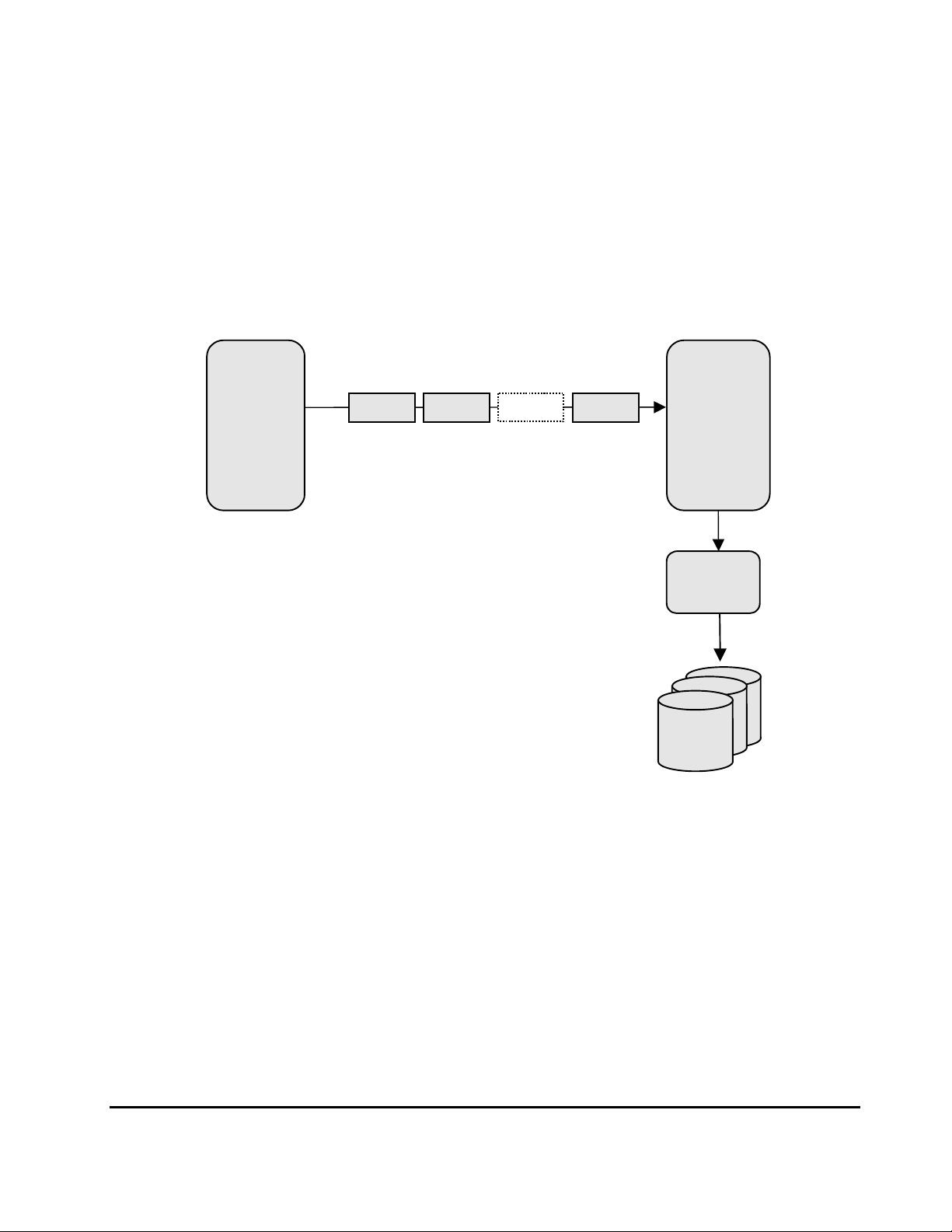
Figure 2-6 illustrates the journal data selection and settling at the secondary
j
p
p
storage system. This diagram shows that journal data S1 arrives at the
secondary storage system because the management information indicates 1.
The secondary storage system selects journal data S1 to be settled, because
S1 is the lowest sequence number. When S1 is removed from the queue of
sequence numbers, journal data S2 becomes the top entry, but it has not
arrived yet. The management information of journal data S2 is 0. The
secondary storage system waits journal data S2. When journal data S2
arrives, the secondary storage system selects S2 as the next journal data to
be settled. The journal data selected by the secondary storage system is
marked as “host-dirty” and treated as formal data.
n
Gr
Receiving
journal data
=
S4 (1) S3 (1)
S2 (0)
S1 (1)
S1 to S4: Sequence number
(1): The journal data arrived.
(0): The journal data has not arrived yet.
Selecting
journal data
S1
Setting
journal data
Formal
ournal
data
Data
Gr
n
=
Figure 2-6 Selecting and Settling Journal at the Secondary Storage
System
The secondary storage system settles and restores the journal data to the
secondary data volume as follows:
• Journal data stored in the cache
The journal data is copied to the corresponding cached track and promoted
to formal data.
Chapter 2 About Universal Replicator Operations 2-27
Hitachi Universal Replicator for IBM /OS User’s Guide
Page 50

• Journal data stored in the restore journal volume
The journal data is read from the restore journal volume to cache. The
journal data that is read to cache is copied to the existing cache track and
promoted to formal data. After that, the space for the restore journal
volume is released.
URz Delta Resync Operation
When you are using URz and TCz Synchronous in a 3DC multi-target
configuration, URz provides delta resync operation as one of the solutions for
failures in primary site. In a 3DC multi-target configuration, there are one
primary site and two secondary sites; TCz Synchronous and URz secondary
sites. For detailed information about 3DC multi-target configuration, see
section
If a failure occurs on the primary site in 3DC multi-target configuration, you
need to use Business Continuity Manager to use the TCz Synchronous
secondary site as the primary site. If you perform a delta resync operation
after the TCz Synchronous secondary site becomes a primary site. The URz
pair will be restored quickly by the delta resync operation, you will not need to
wait for a long time before you can use the URz data volumes again.
TCz Synchronous (3DC Multi-target Configuration).
Delta resync operation consists of the two processes; one is the process for
the preparation before the failure occurs, the other is the process for the
recovery after the failure occurs.
• Processing for the preparation before the failure occurs (see the next
section)
• Processing for the recovery after the failure occurs (see section Switching
the Master Journal Group of URz)
Journal Obtain in TCz Synchronous Secondary Site
To perform delta resync operation when a failure occurs, you also need to
obtain the journal data in the TCz Synchronous secondary site of 3DC multitarget configuration. Specify the TCz Synchronous R-VOL in TCz Synchronous
secondary site as the primary data volume, and specify the data volume in
URz secondary site as the secondary data volume, in order to create a URz
pair for the delta resync operation.
When you create a URz pair for delta resync operation, the differential data of
data volumes in TCz Synchronous primary site and secondary site will be
stored in the journal volumes in TCz Synchronous secondary site as journal
data. The following figure shows an example.
2-28 Chapter 3 Preparing for Universal Replicator z/OS Operations
Hitachi Universal Replicator for IBM /OS User’s Guide
Page 51

TCz Synchronous, URz primary site
j
j
j
URz secondary site
primary host
Write
M-VOL
primary data VOL
primary subsystem
Copying by TCz
Synchronous
ournal obtain
master JNL VOL
TCz Synchronous
secondary site
journal
copy
secondary
host
secondary host
ournal restore
secondary
dataVOL
restore JNL VOL
secondary subsystem
ournal obtain
R-VOL
primary data VOL
master JNL VOL
secondary subsystem
Data flow
URz pair for delta resync operation
Journal data flow
Figure 2-7 Delta Resync Setting in 3DC Mul ti-target C onfiguration
(Before Failure Occurs)
As shown in
Chapter 2 About Universal Replicator Operations 2-29
Hitachi Universal Replicator for IBM /OS User’s Guide
Page 52

Figure 2-7, a URz pair created with the delta resync option is defined as a pair
but no copy operation is performed (Hold status). Actual copy operation will
not be performed until when the failure occurs and delta resync operation is
performed. Note that there are several requirements to create a URz pair for
delta resync operation, such as you need to specify the unused mirror ID. For
detailed information about the requirements of creating a URz pair for delta
resync operation, see section
Requirements for Creating URz Pair for Delta
Resync Operation.
For the information about the delta resync operation that will be performed
when a failure occurs in the configuration shown in
Figure 2-7, see the next section. Note that the URz pair need to be in Hold
status if you want to form the delta resync operation when the failure occurs.
However, the URz pair status may be changed to Hlde for example when the
cache memory or shared memory error occurs in TCz Synchronous secondary
site, or when no journal cannot be obtained in TCz Synchronous secondary site
because of the failure in the master journal volume or occurrence of the
pinned track. If the status of the URz pair for delta resync operation changes
to Hlde, follow the steps in section
Restoring a Pair of Data Volumes and
change the pair status to Hold again.
Switching the Master Journal Group of URz
When a failure occurs on the primary site in
Figure 2-7 (3DC multi-target configuration), the URz pair for delta resync
operation can use the journal group in TCz Synchronous secondary site as the
master journal group. To switch the master journal group, first change TCz
Synchronous secondary site to the primary site by using Business Continuity
Manager, then perform the delta resync operation on the primary data volume
of the URz pair in Hold status. The following figure shows an example.
2-30 Chapter 3 Preparing for Universal Replicator z/OS Operations
Hitachi Universal Replicator for IBM /OS User’s Guide
Page 53

j
j
TCz Synchronous, UR primary site A URz secondary site
primary host secondary host
M-VOL
primary data VOL
Failure
primary
subsystem
master
JNL VOL
TCz Synchronous
primary site B
(former secondary site)
primary host
(former
secondary host)
Write
primary data VOL
(former R-VOL)
ournal restore
secondary
dataVOL
restore
JNL VOL
secondary
subsystem
ournal copy
journal obtain
master
JNL VOL
primary subsystem
(former secondary subsystem)
Data flow
URz pair for delta resync operation
Journal data flow
Figure 2-8 Delta Resync Setting in 3DC Mul ti-target C onfiguration
(After Failure Occurred)
Chapter 2 About Universal Replicator Operations 2-31
Hitachi Universal Replicator for IBM /OS User’s Guide
Page 54

In Figure 2-8, because a failure occurs in the primary site A, Business
Continuity Manager is used to change the former TCz Synchronous secondary
site to the primary site B. If you perform delta resync operation in this
situation, the URz pair for delta resync operation in
synchronized and usable.
When you perform delta resync operation, first the journal data in the primary
site B are copied to the URz secondary site by journal copy. In this journal
copy, only the journal data which is not yet restored to the secondary data
volume in the URz secondary site are copied in chronological order. When the
journal copy completes, journal restore takes place in the URz secondary site.
In delta resync operation, the status of the URz pair will not change to Pending
Duplex but Duplex. This is because delta resync operation copies only the
really necessary data by journal copying. Compared to the usual way which
copies the whole data in the primary data volume, delta resync operation
requires shorter time for the recovery of the URz pair after a failure occurs.
Note: When the total capacity of stored journal data exceeds 80% of the
journal volume of TCz Synchronous secondary site, old journal data will be
deleted automatically. Therefore, if the total capacity of the journal data which
is not restored to the URz secondary data volume exceeds 80% of the journal
volume, the secondary data volume will not be able to be restored completely
by copying the journal data to the restore journal volume in the URz
secondary site. In that case, according to the setting of the journal group
option, whole data in the primary data volume will be copied to the secondary
data volume, or delta resync operation finishes without any processing.
Figure 2-7 will be
Usually, if the pair between TCz Synchronous primary site and secondary site
is synchronized periodically, the total capacity of the journal data which is not
restored to the URz secondary site will not exceed 80% of the journal volume.
Though, for example if the URz pair is suspended and the pair has not been
resynchronized for a long time, journal data of more than 80% of the journal
volume capacity may be stored before they are restored to URz secondary
data volume. In such case, note that you may not perform delta resync
operation properly.
Warning: Even if the capacity of the journal data does not exceed 80% of the
journal volume, note that journal data will or may be destroyed in the
following cases.
• When you restore the TCz Synchronous pair, then updated the M-VOL
• When you restore the URz pair between the primary site and the URz
secondary site, then updated the M-VOL
• When the retry processing occurs because of a delay of the M-VOL update
• When the update of the TCz Synchronous R-VOL is delayed
2-32 Chapter 3 Preparing for Universal Replicator z/OS Operations
Hitachi Universal Replicator for IBM /OS User’s Guide
Page 55

As shown in Figure 2-8, after delta resync operation is performed properly and
the primary site A is recovered from the failure, then the URz pair between the
primary site A and the URz secondary site will be the pair for delta resync
operation and become prepared for the failure in the primary site B. For
information about the requirements to perform delta resync operation properly,
see section
Pair Status
URz displays the pair status for each data volume of specified CU Image (CUI)
in the connected USP V storage system.
data volume pair status descriptions. The primary storage system maintains
the status of the primary data volume and can change the pair status of the
primary data volume and secondary data volume. The secondary storage
system maintains the status of the secondary data volume and can change the
pair status of the secondary data volume but not the primary data volume.
The primary storage system will detect when the secondary storage system
changes the secondary data volume status (if the path status is normal) and
will change the primary data volume status accordingly. You can display the
detailed pair status information at the Storage Navigator remote console PC
(URz Pairdisplay window) or at the host processor (Business Continuity
Manager Pairdisplay command).
Requirements for Performing Delta Resync Operation.
Table 2-4 lists and describes the URz
A volume which is not assigned to a URz data volume pair has the status
simplex. When a URz data volume pair is started, the primary storage system
changes the status of the primary data volume and secondary data volume to
pending duplex. When the initial copy operation is complete, the primary
storage system changes the status of both data volumes to duplex. When a
pair is suspended from the primary storage system, the primary storage
system changes the status of the primary data volume and secondary data
volume (if the path status is normal) to suspended. When a pair is suspended
from the secondary storage system, the secondary storage system changes
the status of the secondary data volume to suspended, and the primary
storage system detects the pair suspension (if the path status is normal) and
changes the primary data volume status to suspended. When you release a
pair from the primary storage system, the primary storage system changes
the status of the primary data volume and secondary data volume (if the path
status is normal) to simplex. When you release a pair from the secondary
storage system, the secondary storage system changes the secondary data
volume status to simplex, and the primary storage system detects the pair
release (if the path status is normal) and changes the primary data volume
status to suspended.
When a URz data volume pair is split or suspended, the primary storage
system generates a service information message (SIM) to notify the host(s). If
SNMP is installed and operational for USP V, this SIM results in an SNMP trap
which indicates the reason for suspension.
Chapter 2 About Universal Replicator Operations 2-33
Hitachi Universal Replicator for IBM /OS User’s Guide
Page 56

• URz Pair Status
The URz Suspending and Deleting (release) transitional states occur when
a request to change URz pair status has been accepted, but the change to
the requested status (suspended, or simplex) is not yet complete. These
states are not reported to the host. In the case of Suspending, both the
user and the primary storage system can request the status change. In the
case of Deleting (release), only the user can request the status change. If
the user requested the status change, the final status is reported at the
end of the transition. If an error caused the status to change to suspended,
the suspended status is reported at the beginning of the transition.
After a storage system receives a request for splitting or releasing a pair in
Flush mode, the status of the pair will remain Suspending or Deleting
until the journal in the master journal group is restored into the restore
journal group and the pair is completely split or released. To calculate the
time during which the pair remains Suspending or Deleting, use the
following equation:
C × (u ÷ 100) × 1,024 ÷ V (The unit is seconds)
where:
– C is the total capacity of the master journal volume. The unit is
megabytes.
– u is the usage rate of data in the master journal volume. The unit is
percent.
– V is the data transfer speed between the primary and the secondary
storage system. The unit is MB/s (megabytes per second).
To find the usage rate of a journal volume, use the monitoring feature (see
Usage Monitor Window).
The URz SEQCHK status is indicated when a URz pair assigned to a
consistency group with the System timer type accepts a non-timestamped update from the primary system. The SEQCHK status does not
affect URz copy activities and will be removed when the next time-stamped
update is successfully copied to the secondary data volume. However, if a
disaster or system failure occurs before the next time-stamped update, the
update sequence consistency between the secondary data volume and
other secondary data volumes in the consistency group is not ensured. To
ensure effective disaster recovery, you should detect and remove the
source of the SEQCHK status. The SEQCHK status can be caused by any of
the following:
– An application may issue update I/Os bypassing the MVS standard I/O
procedure.
– The I/O time-stamping function may not be active at the primary site.
– This URz pair status describes:
• URz suspend types (see the next section),
• URz suspension condition (see section
Suspension Condition).
2-34 Chapter 3 Preparing for Universal Replicator z/OS Operations
Hitachi Universal Replicator for IBM /OS User’s Guide
Page 57

Table 2-4 URz Data Volume Pair Status
Pair Status Description
Simplex
Pending Duplex
Duplex
Suspended
Table 2-5 for
(see
suspend types)
This volume is not currently assigned to a URz data volume pair. This volume
does not belong in the journal group. When this volume is added to a URz data
volume pair, its status will change to pending duplex.
The initial copy operation for this pair is in progress. This data volume pair is not
yet synchronized. When the initial copy is complete, the status changes to
duplex.
This data volume pair is synchronized. Updates to the primary data volume are
duplicated on the secondary data volume.
This data volume pair is not synchronized.
– When the primary storage system detects a URz suspension condition (see
section
Suspension Condition), the primary storage system changes the primary
data volume status and secondary data volume status (if possible) to
suspended.
– When the secondary storage system detects a URz suspension condition (see
section
Suspension Condition), the secondary storage system changes the
secondary data volume status to suspended.
– When you suspend a pair from the primary storage system, the prim ary storage
system changes the status of the primary data volume and secondary data
volume (if possible) to suspended. When you suspend a pair from the
secondary storage system, the secondary storage system changes the status of
the secondary data volume to suspended.
– When the primary storage system detects that the pair was suspended or
released from the secondary storage system, the primary storage system
changes the status of the primary data volume to suspended.
Suspending
Deleting
(releasing)
SEQCHK
Hold
Hlde
This pair is not synchronized. This pair is in transition from duplex or pending
duplex to suspended. When the suspension is requested (by user, primary
storage system, or secondary storage system), the status of all affected pairs
changes to suspending. When the suspension is complete, the status changes to
suspended.
This pair is not synchronized. This pair is in transition from duplex, pending
duplex, or suspended to simplex. When the delete pair operation is requested
(by user), the status of all affected pairs changes to deleting (releasing). When
the delete pair operation is complete, the status changes to simplex.
The secondary storage system encountered a non-time-stamped journal data
for a URz pair using the System timer type option. This status can be displayed
at the primary storage system and secondary storage system, but the primary
storage system may not have the most current information. Always use the pair
status information displayed at the secondary storage system for disaster
recovery.
The pair is prepared for delta resync operation. When the status of primary data
volume is Hold, the write data for the TCz Synchronous R-VOL is stored in the
master journal volume.
Only the delta resync operation, releasing operation, or changing pair option
operation are allowed on the pairs in Hold status.
An error occurred on the pair in Hold status. When the status of primary data
volume is Hlde, the write data for the TCz Synchronous S-VOL will not be stored
in the master journal volume.
Only recovering pair status to standby (Hold) operation, releasing operation, or
changing pair option operation are allowed on the pairs in Hlde status.
Chapter 2 About Universal Replicator Operations 2-35
Hitachi Universal Replicator for IBM /OS User’s Guide
Page 58

Suspend Types
Table 2-5 lists and describes the URz suspend types, which indicate the reason
for the suspension. A URz pair can be suspended by the user at any time after
the initial copy operation is complete. The user must suspend a URz pair in
order to perform ICKDSF maintenance on the primary data volume or to
access the secondary data volume (read only mode).
When a URz pair is suspended by the user, the primary storage system and
secondary storage system ensure synchronization by either completing or
discarding any pending update copy operations according to the user-specified
drain/purge suspend option.
A URz pair is suspended by the primary storage system when the following
suspension conditions are detected. A URz pair can also be suspended by the
secondary storage system (see section
• When the primary storage system detects that the user has released the
volume pair from the secondary storage system (e.g., to access an
secondary data volume at the secondary site),
• When the primary storage system detects an error condition related to the
secondary storage system, secondary data volume, or a URz journal data
operation,
Suspension Condition).
• When the secondary storage system cannot execute DFW (DASD fast
write) to the secondary data volume (only if DFW required is selected), or
• When the primary storage system is unable to communicate with the
secondary storage system.
For more information on URz journal data operations, see section
Condition.
When a URz pair is suspended, the primary storage system stops performing
update copy operations to the secondary data volume. Moreover, the primary
storage system and secondary storage system keep track of any journal data
that were discarded during suspension, and the primary storage system
continues accepting write I/Os for the primary data volume and keeps track of
the primary data volume tracks which are updated while the pair is suspended.
A suspended URz secondary data volume has an additional status called the
consistency status which is displayed only at the secondary storage system. The
consistency status of a suspended URz secondary data volume indicates its
update sequential consistency with respect to the other secondary data volumes
in the same group.
Table 2-7 lists and describes the consistency status descriptions for suspended
URz secondary data volumes.
When a URz pair is suspended, whether user-requested or due to failure, the
primary storage system generates sense information to notify the host(s).
Suspension
2-36 Chapter 3 Preparing for Universal Replicator z/OS Operations
Hitachi Universal Replicator for IBM /OS User’s Guide
Page 59
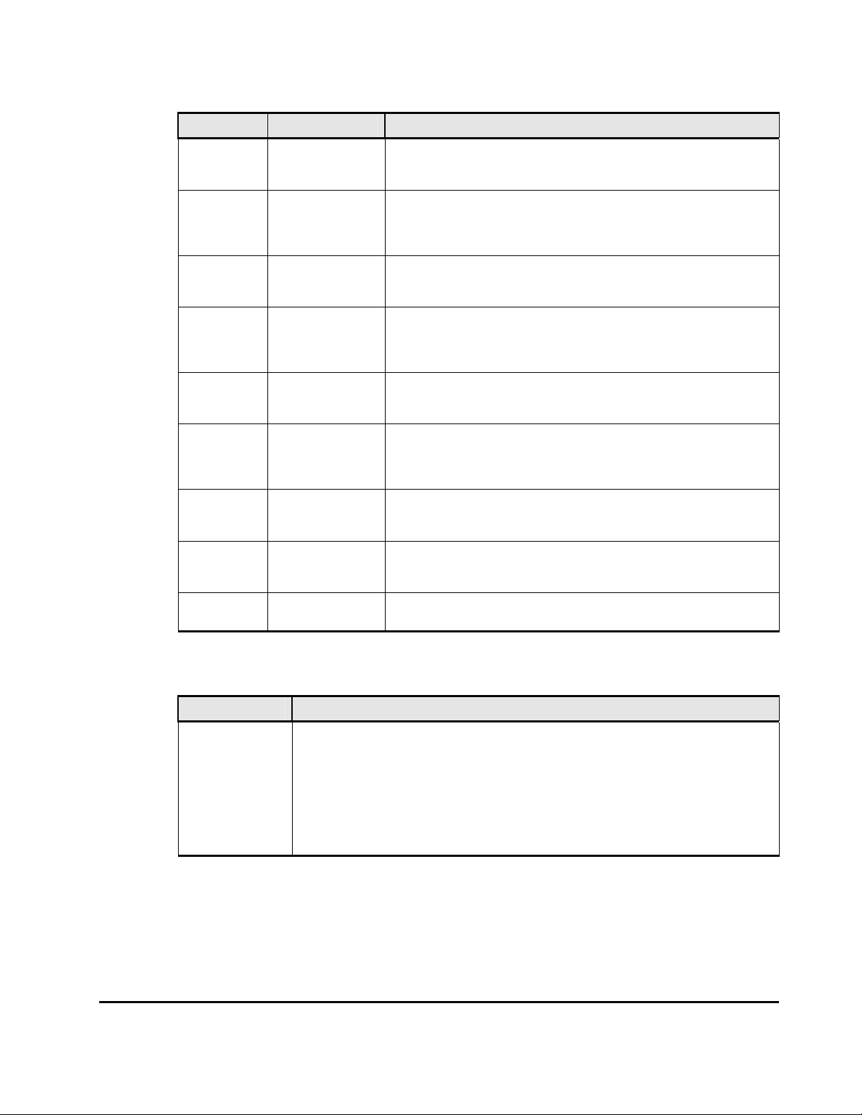
Table 2-5 Suspend Types
Suspend Type Applies to Description
Secondary
data volume
by operator
By MCU Secondary data
By RCU Primary data
Delete Pair to
RCU
Secondary
Data Volume
Failure
MCU IMPL Primary data
Initial Copy
failed
JNL Cache
Overflow
Primary data
volume, secondary
data volume
volume
volume
Primary data
volume
Primary data
volume
volume, secondary
data volume
Primary data
volume, secondary
data volume
Primary data
volume, secondary
data volume
The user suspended the pair from the primary storage system or
secondary storage system using the secondary data volume option.
The secondary storage system received a request from the primary storage
system to suspend the volume pair. The primary data volume suspend
type is Primary data volume by Operator or Secondary data volume by
Operator.
The primary storage system detected an error condition at the secondary
storage system which caused the primary storage system to suspend the
URz volume pair. The secondary data volume suspend type is By MCU.
The primary storage system detected that the secondary data volume
status changed to simplex because the user released the pair from the
secondary storage system. The pair cannot be resumed because the
secondary data volume does not have the suspended status.
The primary storage system detected an error during communication with
the secondary storage system or an I/O error during update copy. In this
case, the secondary data volume suspend type is usually By MCU.
The primary storage system could not find valid control information in its
nonvolatile memory during the IMPL procedure. This condition occurs only
if the primary storage system is completely without power for more than
48 hours (e.g., power failure and fully discharged backup batteries).
The volume pair was suspended before the initial copy operation was
complete. The data on the secondary data volume is not identical to the
data on the primary data volume.
The data volume pair was suspended because it was highly likely that
journal data will overflow.
MCU P/S OFF Secondary data
volume
The primary storage system is powered off.
Table 2-6 Consistency Status for Suspended URz Secondary Data
Volumes
Consistency Status Description
Volume This URz volume pair was suspended alone. Update sequence consistency between this
Chapter 2 About Universal Replicator Operations 2-37
secondary data volume and other secondary data volumes in this journal group is not
ensured. This secondary data volume cannot be used for disaster recovery at the secondary
system. This status is indicated when:
– This volume pair was suspended by a user-initiated suspend pair operation with the
URz Suspend option set to Volume.
– This volume pair was suspended due to a failure that did not a ffect the entire
consistency group, and the Error Level pair option for this pair is se t to Volume.
Hitachi Universal Replicator for IBM /OS User’s Guide
Page 60

Group This URz volume pair was suspended along with the other pair in its journal group. Update
sequence consistency between this secondary data volume and other secondary data
volumes in this journal group is ensured. This secondary data volume can be used for disaster
recovery at the secondary system (after releasing the URz volume pair from the secondary
storage system). This status is indicated when:
– This volume pair was suspended by a user-initiated suspend pair operation with the
URz Suspend option set to Group.
– All volume pairs in this journal group were suspended due to a failure that affected
the entire journal group (not just one pair) (e.g., primary storage s ystem-secondary
storage system communication failure).
– The volume pair was suspended due to a failure that did not affect the entire group.
Suspension Condition
URz operations also involve suspension conditions related to asynchronous
operations. Both the primary storage system and secondary storage system
can detect URz suspension conditions and suspend URz pairs.
The URz suspension conditions described in
detects the condition and which pairs are suspended. See section
Table 2-7 and indicates which CU
General
Troubleshooting for troubleshooting information for URz suspension conditions.
Table 2-7 URz Suspension Condition
Suspension Condition Detected by: URz Pairs to be Suspended
The secondary storage system could not copy the
journal data successfully due to a hardware failure or
logic error.
The secondary storage system detected a logical error
while selecting the journal data to be restored.
The secondary storage system could not restore the
journal data due to a hardware failure, track condition,
or logical error.
RCU
RCU
RCU
All URz secondary data volumes in the
journal groups, or the affected
secondary data volume.
All the URz secondary data volumes in
the journal group, or only the affected
secondary data volume, depending on
the type of failure.
The primary storage system stores the differential bitmap per URz primary
data volume in the shared memory. The secondary storage system stores the
differential bitmap per URz secondary data volume in the shared memory.
When a URz pair is suspended, the tracks which contain the following journal
are marked in the differential bitmap as modified (to be copied during the
resume pair operation):
• The journal data that were created by the primary storage system but not
yet sent to the secondary storage system.
After marking these primary data volume tracks as modified, the primary
storage system discards these journal data.
• The journal data that were sent to the secondary storage system but not
acknowledged by the secondary storage system.
2-38 Chapter 3 Preparing for Universal Replicator z/OS Operations
Hitachi Universal Replicator for IBM /OS User’s Guide
Page 61

After marking these primary data volume tracks as modified, the primary
storage system discards these journal data. This ensures that journal data
lost during transmission to the secondary storage system are identified and
marked.
• The journal data that reached the secondary storage system but have not
yet been settled.
After marking these secondary data volume tracks as modified, the
secondary storage system discards these journal data.
• The primary data volume records updated by host-requested write I/Os
after the pair was suspended.
When a suspended URz pair is resumed (resynchronized), the contents of the
secondary storage system’s cylinder/track bitmap are sent to the primary
storage system and merged into the primary storage system’s bitmap. The
primary storage system then performs the resync operation according to the
merged bitmap. This ensures that all the tracks including the discarded journal
data are resynchronized at this time.
Business Continuity Manager Support
The USP V storage systems on which URz is installed support the Business
Continuity Manager commands. If the host system console issues the Business
Continuity Manager commands to the USP V storage system, the URz pair
operations can be performed. The Business Continuity Manager commands
allow you to add pairs, suspend pairs, resume pairs, release pairs, monitor the
pair status, add DKC, and delete DKC.
USP V system adapter ID(SAID) values. For further information and
instructions on Business Continuity Manager, please refer to the Business
Continuity Manager User's Guide.
Table 2-8 and Table 2-9 explain the
Chapter 2 About Universal Replicator Operations 2-39
Hitachi Universal Replicator for IBM /OS User’s Guide
Page 62

Table 2-8 SAID Values for the PATH LINK Parameter (FRONT CL1)
Package
Location
1E CL1-A
(Basic) CL3-A
CL5-A
CL7-A
CL1-B
CL3-B
CL5-B
CL7-B
CL1-C
CL3-C
CL5-C
CL7-C
CL1-D
CL3-D
CL5-D
CL7-D
1F CL1-E
(Add1) CL3-E
CL5-E
CL7-E
CL1-F
CL3-F
Port SAID Package
X'000
0'
X'002
0'
X'004
0'
X'006
0'
X'000
1'
X'002
1'
X'004
1'
X'006
1'
X'000
2'
X'002
2'
X'004
2'
X'006
2'
X'000
3'
X'002
3'
X'004
3'
X'006
3'
X'000
4'
X'002
4'
X'004
4'
X'006
4'
X'000
5'
X'002
5'
Location
1G CL1-J X'0008' 1K CL9-N X'008C' 1B CL9-E X'0084'
(Add2) CL3-J X'0028' (Add4) CLB-N X'00AC' (Add6) CLB-E X'00A4'
CL5-J X'0048' CLD-N X'00CC' CLD-E X'00C4'
CL7-J X'0068' CLF-N X'00EC' CLF-E X'00E4'
CL1-K X'0009' CL9-P X'008D' CL9-F X'0085'
CL3-K X'0029' CLB-P X'00AD' CLB-F X'00A5'
CL5-K X'0049' CLD-P X'00CD' CLD-F X'00C5'
CL7-K X'0069' CLF-P X'00ED' CLF-F X'00E5'
CL1-L X'000A' CL9-Q X'008E' CL9-G X'0086'
CL3-L X'002A' CLB-Q X'00AE' CLB-G X'00A6'
CL5-L X'004A' CLD-Q X'00CE' CLD-G X'00C6'
CL7-L X'006A' CLF-Q X'00EE' CLF-G X'00E6'
CL1-M X'000B' CL9-R X'008F' CL9-H X'0087'
CL3-M X'002B' CLB-R X'00AF' CLB-H X'00A7'
CL5-M X'004B' CLD-R X'00CF' CLD-H X'00C7'
CL7-M X'006B' CLF-R X'00EF' CLF-H X'00E7'
1H CL1-N X'000C' 1L CL9-J X'0088' 1A CL9-A X'0080'
(Add3) CL3-N X'002C' (Add5) CLB-J X'00A8' (Add7) CLB-A X'00A0'
CL5-N X'004C' CLD-J X'00C8' CLD-A X'00C0'
CL7-N X'006C' CLF-J X'00E8' CLF-A X'00E0'
CL1-P X'000D' CL9-K X'0089' CL9-B X'0081'
CL3-P X'002D' CLB-K X'00A9' CLB-B X'00A1'
Port SAID Package
Location
Port SAID Package
Location
Port SAID
2-40 Chapter 3 Preparing for Universal Replicator z/OS Operations
Hitachi Universal Replicator for IBM /OS User’s Guide
Page 63

CL5-F
CL7-F
CL1-G
CL3-G
CL5-G
CL7-G
CL1-H
CL3-H
CL5-H
CL7-H
X'004
5'
X'006
5'
X'000
6'
X'002
6'
X'004
6'
X'006
6'
X'000
7'
X'002
7'
X'004
7'
X'006
7'
Table 2-9 SAID Values for the PATH LINK Parameter (REAR CL2)
CL5-P X'004D' CLD-K X'00C9' CLD-B X'00C1'
CL7-P X'006D' CLF-K X'00E9' CLF-B X'00E1'
CL1-Q X'000E' CL9-L X'008A' CL9-C X'0082'
CL3-Q X'002E' CLB-L X'00AA' CLB-C X'00A2'
CL5-Q X'004E' CLD-L X'00CA' CLD-C X'00C2'
CL7-Q X'006E' CLF-L X'00EA' CLF-C X'00E2'
CL1-R X'000F' CL9-M X'008B' CL9-D X'0083'
CL3-R X'002F' CLB-M X'00AB' CLB-D X'00A3'
CL5-R X'004F' CLD-M X'00CB' CLD-D X'00C3'
CL7-R X'006F' CLF-M X'00EB' CLF-D X'00E3'
Package
Location
2Q CL2-A X'0010' 2T CL2-J X'0018' 2W CLA-N X'009C' 2N CLA-E
(Basic) CL4-A X'0030' (Add2) CL4-J X'0038' (Add4) CLC-N X'00BC' (Add6) CLC-E
CL6-A X'0050' CL6-J X'0058' CLE-N X'00DC' CLE-E
CL8-A X'0070' CL8-J X'0078' CLG-N X'00FC' CLG-E X'00F4'
CL2-B X'0011' CL2-K X'0019' CLA-P X'009D' CLA-F
CL4-B X'0031' CL4-K X'0039' CLC-P X'00BD' CLC-F
CL6-B X'0051' CL6-K X'0059' CLE-P X'00DD' CLE-F
CL8-B X'0071' CL8-K X'0079' CLG-P X'00FD' CLG-F X'00F5'
CL2-C X'0012' CL2-L X'001A' CLA-Q X'009E' CLA-G
CL4-C X'0032' CL4-L X'003A' CLC-Q X'00BE' CLC-G
CL6-C X'0052' CL6-L X'005A' CLE-Q X'00DE' CLE-G
CL8-C X'0072' CL8-L X'007A' CLG-Q X'00FE' CLG-G X'00F6'
CL2-D X'0013' CL2-M X'001B' CLA-R X'009F' CLA-H
Port SAID Package
Location
Port SAID Package
Location
Port SAID Package
Location
Port SAID
X'0094
'
X'00B4
'
X'00D4
'
X'0095
'
X'00B5
'
X'00D5
'
X'0096
'
X'00B6
'
X'00D6
'
X'0097
'
Chapter 2 About Universal Replicator Operations 2-41
Hitachi Universal Replicator for IBM /OS User’s Guide
Page 64

CL4-D X'0033' CL4-M X'003B' CLC-R X'00BF' CLC-H
CL6-D X'0053' CL6-M X'005B' CLE-R X'00DF' CLE-H
CL8-D X'0073' CL8-M X'007B' CLG-R X'00FF' CLG-H X'00F7'
2R CL2-E X'0014' 2U CL2-N X'001C' 2X CLA-J X'0098' 2M CLA-A
(Add1) CL4-E X'0034' (Add3) CL4-N X'003C' (Add5) CLC-J X'00B8' (Add7) CLC-A
CL6-E X'0054' CL6-N X'005C' CLE-J X'00D8' CLE-A
CL8-E X'0074' CL8-N X'007C' CLG-J X'00F8' CLG-A X'00F0'
CL2-F X'0015' CL2-P X'001D' CLA-K X'0099' CLA-B
CL4-F X'0035' CL4-P X'003D' CLC-K X'00B9' CLC-B
CL6-F X'0055' CL6-P X'005D' CLE-K X'00D9' CLE-B
CL8-F X'0075' CL8-P X'007D' CLG-K X'00F9' CLG-B X'00F1'
CL2-G X'0016' CL2-Q X'001E' CLA-L X'009A' CLA-C
CL4-G X'0036' CL4-Q X'003E' CLC-L X'00BA' CLC-C
CL6-G X'0056' CL6-Q X'005E' CLE-L X'00DA' CLE-C
CL8-G X'0076' CL8-Q X'007E' CLG-L X'00FA' CLG-C X'00F2'
CL2-H X'0017' CL2-R X'001F' CLA-M X'009B' CLA-D
CL4-H X'0037' CL4-R X'003F' CLC-M X'00BB' CLC-D
CL6-H X'0057' CL6-R X'005F' CLE-M X'00DB' CLE-D
CL8-H X'0077' CL8-R X'007F' CLG-M X'00FB' CLG-D X'00F3'
X'00B7
'
X'00D7
'
X'0090
'
X'00B0
'
X'00D0
'
X'0091
'
X'00B1
'
X'00D1
'
X'0092
'
X'00B2
'
X'00D2
'
X'0093
'
X'00B3
'
X'00D3
'
Command Device
To use Business Continuity Manager, you must set the command device for it
separately from the command device for an open system. The command
device for Business Continuity Manager can be set only from Business
Continuity Manager. For information about Business Continuity Manager,
please refer to the Business Continuity Manager User Guide and Reference.
2-42 Chapter 3 Preparing for Universal Replicator z/OS Operations
Hitachi Universal Replicator for IBM /OS User’s Guide
Page 65

You can use Storage Navigator to find the command device for Business
Continuity Manager. To find the command device, click File, and Basic
Information on the menu bar of the Storage Navigator main window, and
then select the LDEV tab in the Basic Information Display window. For
detailed information on the Basic Information Display window, please refer
to the Storage Navigator User's Guide.
Chapter 2 About Universal Replicator Operations 2-43
Hitachi Universal Replicator for IBM /OS User’s Guide
Page 66

2-44 Chapter 3 Preparing for Universal Replicator z/OS Operations
Hitachi Universal Replicator for IBM /OS User’s Guide
Page 67

3
Preparing for Universal Replicator z/OS
Operations
This chapter describes URz operations involving the USP V primary and
secondary storage systems, the remote copy connections between the primary
\secondary storage systems, and the host(s) at the primary and secondary
sites, as well as the licensed URz remote console software:
Requirements and Restrictions for URz
Installing the Hardware
Enabling the URz Option(s)
Using Multiple Primary and Secondary Storage Systems
Interoperability with Other Products and Functions
Planning of Journal Volumes
Contributing Factors for Data Transfer Speed between Storage Systems
Configuration that TagmaStore USP/NSC and USP V is Connected
Chapter 3 Preparing for Universal Replicator z/OS Operations 3-1
Hitachi Universal Replicator for z/OS User’s Guide
Page 68

Requirements and Restrictions for URz
URz has the following requirements and restrictions:
• System requirements (see the next section)
• Disk track format
• One-to-one volume copy operations
• Duplicate VOLSER
• Volume type
• Journal group
• Accessing URz primary data volumes and secondary data volumes
• Cache and NVS
• Duplicate volume
System Requirements
URz operations involve the USP V primary storage systems and secondary
storage systems containing the primary and secondary data volumes, the
remote copy connections between the primary storage systems and secondary
storage systems, the host(s) at the primary and secondary sites, and the
licensed URz remote console software. The URz system requirements are:
• primary storage system: USP V storage system with URz installed.
• secondary storage system: USP V storage system with URz installed.
Note: URz can coexist with UR in the same USP V storage system.
Note: The remote copy connection with the NAS interface is not supported.
• Remote copy connections – fibre channel (see section Setting up Remote
Copy Connections):
• Multimode or single-mode optical fibre cables are required at both the
primary storage system and secondary storage system.
• For distance up to 0.5 km, multimode optical shortwave fiber cables are
required between the primary storage system and secondary storage
system.
• For distances from 0.5 km to 1.5 km (1,640 to 4,920 feet), multimode
shortwave fibre-channel interface cables with up to two switches are
required.
• For distance up to 10 km, single optical long wave fiber cables are required
between the primary storage system and secondary storage system.
• For distances from 10 km to 30 km (6.2 to 18.6 miles), single-mode long
wave fibre-channel interface cables with up to two switches are required.
3-2 Chapter 3 Preparing for Universal Replicator z/OS Operations
Hitachi Universal Replicator for IBM /OS User’s Guide
Page 69

• For distances greater than 30 km (18.6 miles), approved third-party
channel extender products and telecommunications lines are required.
Long-distance URz solutions are provided based on user requirements and
workload characteristics.
• Supported mainframe host operating systems (OS):
USP V supports the following mainframe host operating systems (OS).
– MVS, OS/390, z/OS, VOS3, MSP-EX
– Optional error report communications (ERC) function requires MVS/DFP
3.2.0 or later.
– If the primary and/or secondary systems consist of several CPU
complexes, a SYSPLEX timer is required to provide a common time
reference for the host I/O time-stamping function.
Please contact your Hitachi account team for the latest information on
platform support for URz.
• A computer that runs Storage Navigator (Storage Navigator computer):
The USP V Storage Navigator remote console software is required for
USP V URz operations. The URz remote console software is a component of
the USP V Storage Navigator software. The URz license key(s) are required
to enable the URz option(s) on the USP V storage system (see section
Enabling the URz Option(s)). Separate license keys are required for each
USP V storage system. For further information on USP V Storage Navigator
operations, please refer to the Storage Navigator User's Guide, or contact
your Hitachi account team.
Note: Administrator or URz write access to the USP V Storage Navigator Java
applet program is required to perform URz operations. Users without
Administrator or URz write access can only view URz information.
• About the license of Universal Replicator for z/OS
If you want to use Universal Replicator for z/OS
a license for Universal Replicator for z/OS
for z/OS
®
.
®
but also a license for TrueCopy
®
:
®
, you must install not only
• Connection with TagmaStore USP/NSC
URz can execute remote copy operations by connecting USP V with
TagmaStore USP/NSC. Specifically, the following configurations are
supported.
– System configuration for remote copy operation using URz from USP V
to TagmaStore USP/NSC.
– System configuration for remote copy operation using URz from
TagmaStore USP/NSC to USP V using.
Note: For detailed information about the connection with TagmaStore
USP/NSC, see section
is Connected.
Configuration that TagmaStore USP/NSC and USP V
Chapter 3 Preparing for Universal Replicator z/OS Operations 3-3
Hitachi Universal Replicator for IBM /OS User’s Guide
Page 70

Disk Track Format
URz supports the following requirements on the disk track format, which must
be ensured by the user. URz cannot detect exceptions to these requirements.
The primary storage system will abort the URz initial copy operation if the
track format for both the primary data volume and secondary data volume
does not meet the following requirements.
• The TCz primary data volume and secondary data volume must have the
same track format.
• Record zero (R0) must be standard format, with key length of zero and
data length of eight. The primary storage system will abort the initial copy
operation if R0 is not standard format.
• The CCHH (logical cylinder address and logical head address) of R0 must
be identical to the physical cylinder address and physical head address of
the track.
• The CCHH of each user record in a track must be unique.
One-to-One Volume Copy Operations
URz requires a one-to-one relationship between the volumes of the volume
pairs. A volume (LDEV) can only be assigned to one URz pair at a time.
However, when creating a URz pair for delta resync operation, you can specify
the secondary data volume of a URz pair that is not for delta resync operation
as the secondary data volume of the URz pair for delta resync operation. In
that case, you need to create a mirror the delta-resync pair and the non-deltaresync pair. For detailed information about delta resync operation, see section
URz Delta Resync Operation and TCz Synchronous (3DC Multi-target
Configuration).
Note: URz does not support operations in which one primary data volume is
copied to more than one secondary data volume, or more than one primary
data volume is copied to one secondary data volume.
Because URz operates on volumes rather than on files, multivolume files
require special attention. For complete duplication and recovery of a
multivolume file (e.g., a large database file which spans several volumes),
make sure that all volumes of the file are copied to URz secondary data
volume, and use URz to ensure update sequence consistency across this group
of secondary data volume.
3-4 Chapter 3 Preparing for Universal Replicator z/OS Operations
Hitachi Universal Replicator for IBM /OS User’s Guide
Page 71

Duplicate VOLSER (Volume Serial Number)
When you select Entire as the initial copy option, the URz initial copy
operation copies the VOLSER of the primary data volume to the secondary
data volume, and therefore the primary data volume and secondary data
volume of the URz pair will have the same VOLSER. Since the host operating
system does not allow duplicate VOLSERs, the host system administrator must
take precautions to prevent system problems related to duplicate VOLSERs.
For example, the URz secondary data volumes must be defined in the system
generation so they do not come online automatically (see WARNING below).
WARNING: If the volumes which will become URz secondary data volumes are
physically attached to the same system images as the production volumes
which will become the URz primary data volumes, the following problems can
occur:
When a URz pair is released, the old secondary data volume is usually offline.
When a host system is IPL’d (initial program loaded), the operator will be
offered both volumes and asked which volume should be left offline – the old
duplicate volser message. This can be confusing and is prone to error. To
avoid duplication of VOLSER,
1. Identify the volumes that will not be accessed by the host system.
2. Perform CHP OFF or some other operation to ensure that the volumes are
inaccessible.
3. When performing IPL, you must perform LOAD CLEAR.
Volume Types
The following DKC and DKU emulation types can be used for the URz software.
Table 3-1 Supported Emulation Types
Emulation Support type
DKC All CU images that can be used with USP V
DKU (Drive) All mainframe volumes that can be used with USP V
All DKC and DKU (drive) emulation types for USP V can be used for URz
software. In URz, the emulation types of primary and secondary data volumes
are indicated.
The following CU emulation types can be used for MCUs (primary storage
systems) and RCUs (secondary storage systems): 3990-3, 3990-6, 3990-6E,
2105, 2107, A-65A2, H-65A2, A-65C1, A-65C2.
The CU emulation type of an MCU can be different from the CU emulation type
of the corresponding RCU.
Chapter 3 Preparing for Universal Replicator z/OS Operations 3-5
Hitachi Universal Replicator for IBM /OS User’s Guide
Page 72

Notes:
• The CU emulation type 3990-6, 3990-6E, 2105, or 2107 is required for
SMS I/O time stamping of URz journals. If one of these CU emulation types
is used, volumes of the 3380 emulation type must not be used.
• The CU emulation type H-65A2 is used for the HITAC M series and supports
all types of M series volumes.
Table 3-2 lists the volumes and the volume capacity that can be used for the
URz data volume and journal volume.
Note: The capacity of journal volume is not included in the accounting capacity.
Table 3-2 Supported Data Volume and Journal Volume
Type
Data Volume Journal Volume
VLL volume Available
The volume on which Cache Residency
Manager setting are made
Maximum volume capacity
3380-3 2.377 GB
3380-E 1.26 GB
3380-J 0.63 GB
3380-K 1.890 GB
3390-1 0.964 GB
3390-2 1.892 GB
3390-3
Available
2.838 GB
3390-3R
3390-9 8.510 GB
3390-L 27.80 GB
3390-M 55.60 GB
OPEN-V
OPEN-V volumes cannot be used
as data volumes.
Support specifications
Capacity of OPEN-V volumes can
be determined freely, depending
on VLL volume specifications. The
minimum capacity is 48.1 MB,
and the maximum capacity is the
same as the user capacity of one
RAID group.
Note: The default capacity of an
OPEN-V volume is the same as the
capacity of a RAID group, and
depends on the hard disk drive type
and the RAID configuration.
3-6 Chapter 3 Preparing for Universal Replicator z/OS Operations
Hitachi Universal Replicator for IBM /OS User’s Guide
Page 73

Minimum volume capacity 1 cylinder
50 cylinders for a non-OPEN-V
volume.
48.1 MB for an OPEN-V volume.
Note: A journal volume consists of
two types of areas, one for
containing journal data, and the
other for containing information for
managing remote copy operations.
Caution: Volumes containing a VMA (volume management area) cannot be used
as journal volumes. For detailed information about a VMA, please refer to the
Data Retention Utility User's Guide.
The table below explains emulation types and the capacity of volumes that can
form pairs. For details on the maximum number of pairs, see the next section.
Table 3-3 Specifications of Volumes that can Form Pairs
Item Support specifications
Emulation type Same emulation type.
Volume capacity The same capaci ty.
URz can copy data between volumes with the same emulation and capacity
(e.g., 3390-3R to 3390-3R). URz also supports the Virtual LVI/LUN feature of
the USP V storage system, enabling you to establish URz pairs with customsize emulation types as well as standard-size emulation types. When customsize emulation types are assigned to URz pairs, the secondary data volume
must have the same capacity as the primary data volume. The URz remote
console software displays the emulation type of the primary data volumes and
secondary data volumes.
URz supports the Virtual LVI/LUN feature of the USP V storage system, which
allows you to configure custom-size LDEVs which are smaller than standardsize LDEVs. When custom-size LDEVs are assigned to a URz pair, the
secondary data volume must have the same capacity as the primary data
volume.
Table 3-4 shows the emulation types and capacity of master and restore
journal volumes that can be used for a URz software.
Table 3-4 Journal Volume Specifications
Item Support specifications
Emulation type Same emulation type.
Volume capacity
Does not matter whether the capacity is the
same or different.
Table 3-5 shows the RAID level combination of data volume and journal
volume in the journal group that can be used for URz.
Chapter 3 Preparing for Universal Replicator z/OS Operations 3-7
Hitachi Universal Replicator for IBM /OS User’s Guide
Page 74

Table 3-5 RAID Level Configuration of URz
Item Support specifications
RAID configuration of data
volume and journal volume
RAID1, RAID5, and RAID6 can coexist.
RAID1, RAID5, and RAID6 can coexist in the same journal group.
The Maximum Number of Pairs
Note: The number of pairs that can be created in a storage system is limited.
Use the number of cylinders and bitmap areas to calculate the maximum
number of pairs that can be created in a storage system.
• The number of cylinders:
The number of pairs of a primary data volume and a secondary data
volume is limited by the number of cylinders of the volumes to be paired
(i.e., the capacity of the volume. If VLL is used, the number of pairs
depends on the number of cylinders specified by VLL.). The limit on the
number of pairs is applied to both the primary storage system and the
secondary storage system.
according to each emulation type.
Table 3-6 illustrates the number of cylinders
Table 3-6 Number of Cylinders According to Each Emulation Type
Emulation type Number of Cylinders
3380-J 885
3380-E 1,770
3380-K 2,655
3390-1 1,113
3390-2 2,226
3390-3
3390-3R
3390-9 10,017
3390-L 32,760
3390-M 65,520
H6586-G 1,770
H6586-J 885
H6586-K 2,655
H6588-1 1,113
H6588-3 3,436
H6588-9 10,017
3,339
3-8 Chapter 3 Preparing for Universal Replicator z/OS Operations
Hitachi Universal Replicator for IBM /OS User’s Guide
Page 75

H6588-L 32,760
NF80-E 1,770
NF80-J 885
NF80-K 2,655
• The number of the required bitmap areas:
The number of bitmap areas to be used by all data volumes that form pairs
is calculated out of the number of cylinders. The calculated number of
bitmap areas is referred to as "the required number of bitmap areas" in
the following formula. Use the following formula to calculate the required
number of bitmap areas for a data volume. The ↑…↑ symbols enclosing a
value indicate that the enclosed value should be rounded up to the nearest
integer.
The required number of bitmap areas = (↑((number of cylinders ×
15) ÷ 122,752) ↑)
– ” number of cylinders × 15” indicates the number of slots
– 122,752 is the number of slots that a bitmap area can manage
Note
: If the calculated required number of bitmap areas exceeds the total
number of bitmap areas in the storage system, the number of pairs that
can be created will be limited.
• The maximum number of pairs that can be created:
The maximum possible number of pairs that can be created depends on the
number of bitmap areas of the storage system and the required number of
bitmap areas required to create pairs.
The number of bitmap areas of the storage system depends on the
capacity of shared memory. The relationship between the area number of
shared memory and the number of bitmap areas in the storage system is
described in Table 3.7.
Table 3-7 The Relationship between Additional Shared Memory and
Total Number of Bitmap Areas of Storage System
Additional Shared Memory for URz Total Number of Bitmap Areas of Storage System
No additional shared memory for URz 0
Additional shared memory for URz is installed 7,424
Extension 1 16,384
Extension 2 32,768
Extension 3 44,256
Extension 4 65,536
Use the following formulae to calculate the maximum possible number of
pairs that can be created, based on the number of bitmap areas described
in
Table 3-7 and the required number of bitmap areas you calculated:
Chapter 3 Preparing for Universal Replicator z/OS Operations 3-9
Hitachi Universal Replicator for IBM /OS User’s Guide
Page 76

The maximum number of pairs = ( ↓ Number of bitmap areas ÷
required number of bitmap areas ↓ )
The ↓…↓ symbols enclosing a value indicate that the value should be rounded down to the nea rest integer.
Note: If the calculated maximum number of pairs exceeds 32,768, the
actual maximum number of pairs is limited to 32,768.
Table 3-8 illustrates the maximum number of pairs according to each
emulation type, when pairs are created without use of VLL volume.
Table 3-8 Maximum Number of Pairs According to Each Emulation Type,
when pairs are created without use of VLL volume
Emulation
Type
Additional
Maximum
number of pairs
Extension 1 Extension 2 Extension 3 Extension 4
shared memory
for URz is
installed
3380-J 7,420 16,384 28,673 32,768 32,768
3380-E 7,420 16,384 28,673 32,768 32,768
3380-K 7,420 16,384 28,673 32,768 32,768
3390-1 7,420 16,384 28,673 32,768 32,768
3390-2 7,420 16,384 28,673 32,768 32,768
3390-3
3390-3R
3390-9 3,710 8,192 14,336 20,071 28,672
3390-L 1,484 3,277 5,734 8,028 11,469
3390-M 1,484 3,277 5,734 8,028 11,469
H6586-G 7,420 16,384 28,673 32,768 32,768
H6586-J 7,420 16,384 28,673 32,768 32,768
H6586-K 7,420 16,384 28,673 32,768 32,768
H6588-1 7,420 16,384 28,673 32,768 32,768
H6588-3 7,420 16,384 28,673 32,768 32,768
H6588-9 3,710 8,192 14,336 20,071 28,672
H6588-L 1,484 3,277 5,734 8,028 11,469
NF80-E 7,420 16,384 28,673 32,768 32,768
NF80-J 7,420 16,384 28,673 32,768 32,768
NF80-K 7,420 16,384 28,673 32,768 32,768
7,420 16,384 28,673 32,768 32,768
Caution: The bitmap areas that are used for URz are also used for TrueCopy for
z/OS. If you use both TrueCopy for z/OS and URz, use the total number of
both pairs.
3-10 Chapter 3 Preparing for Universal Replicator z/OS Operations
Hitachi Universal Replicator for IBM /OS User’s Guide
Page 77

Journal Group
The URz journal groups have the following requirements:
• Each URz pair must be assigned to one and only one journal group. Table
3-9 shows the journal group specifications.
Table 3-9 Journal Group Specifications
Item Support specifications
Number of journal groups
Up to 256 journal groups (No. 0 - 255) per one disk subsystem
Note: The recommended number of journal groups is up to 16.
Number of data volumes in a journal
group
Number of journal volumes in a journal
group
Number of Mirror IDs
Up to 4,096
Up to 64
Up to 4 (ID No.: 0 to 3)
Note: If TCz Sync. uses No. 0, No. 1 to 3 are available f or URz.
The same number of journal volumes is not required in the master journal
group and the restore journal group that are paired.
Mirror ID is required for the configuration that will be supported in the future
within the 3-data center (3DC), including the expected future enhancement to
enable the user to pair one master journal group with two or more restore
journal groups. Each pair relationship in a journal group is called "Mirror".
Mirror ID identifies two or more mirrors that one journal group has. The same
Mirror ID of the journal group is applied to the data volume pair. See section
TCz Synchronous (3DC Cascading Configuration) for 3DC configurations.
• Table 3-10 shows the specifications of relationship between the data
volumes, between the journal volumes, and between the data volumes and
journal volumes in a journal group.
Table 3-10 Journal Group Volume Specifications
Item Support specifications
Emulation
type
Volume
capacity
CLPR
Same emulation type.
Does not matter whether the capacity is the same or different.
Journal volumes and data volumes in the same journal group can belong to different CLPRs.
Journal volumes must belong to the same CLPR. Data volumes must also belong to the same
CLPR.
Note: A primary journal group and the corresponding restore journal group need not belong to the
same CLPR.
Note: When URz and UR coexist in the same USP V storage system, each
journal group must contain either URz pairs or UR pairs (not both).
Chapter 3 Preparing for Universal Replicator z/OS Operations 3-11
Hitachi Universal Replicator for IBM /OS User’s Guide
Page 78

Accessing URz Primary Data Volume and Secondary Data
Volume
To ensure maximum data integrity during normal URz operations, the
secondary storage system rejects all the read/write operations issued by a
host to a URz secondary data volume. If you need write operation to a URz
secondary data volume, you must set the secondary data volume write option
(see section
(Resume Pair) the split pair, the secondary storage system will send the
secondary data volume track bitmap to the primary storage system to ensure
proper resynchronization of the pair.
Secondary Data Volume Write Option). When you resume
Cache and Nonvolatile Storage (NVS)
Cache and nonvolatile storage (NVS) must be operable for both the primary
storage system and secondary storage system of a URz data volume pair. If
not, the URz add pair operation will fail. The remote storage system cache
should be configured to adequately support not only the local workloads but
also the URz remote copy workloads.
Duplicate Volumes
Since the contents of the primary data volume and secondary data volume of
a URz pair are identical, the secondary data volume can be considered a
duplicate of the primary data volume. Since the host operating system does
not allow duplicate volumes, the host system administrator must take
precautions to prevent system problems related to duplicate volumes. You
must define the URz secondary data volume so they do not auto-mount or
come online to the same host at the same time as the primary data volume
(see
WARNING below).
URz does not allow the secondary data volume to be online (except while the
pair is split). If the secondary data volume is online, the URz add pair
operation will fail.
WARNING: If the URz secondary data volumes are physically attached to the same host
server(s) as the URz primary data volumes, the following problem can occur:
When a URz pair is released, the old secondary data volume is usually
offline. If the host is then restarted, the system administrator may be offered
both volumes and asked which volume should be left offline. This can be
confusing and is prone to error.
If the URz secondary data volumes and primary data volumes are connected to the same
host(s), Hitachi strongly recommends that the secondary data volumes are defined to
remain offline to avoid this problem.
3-12 Chapter 3 Preparing for Universal Replicator z/OS Operations
Hitachi Universal Replicator for IBM /OS User’s Guide
Page 79

Installing the Hardware
Initial installation of the URz hardware is performed by the user and the Hitachi
representative. To install the hardware required for URz operations:
1. User: Identify the locations of the URz primary and secondary data
volumes (primary data volumes and secondary data volumes), so that the
URz hardware can be installed and configured properly.
2. User and Hitachi Representative: Make sure that the primary storage
system(s) and secondary storage system(s) are configured for USP V
Storage Navigator operations (e.g., SVP connected to LAN). Refer to the
Storage Navigator User’s Guide for information and instructions on setting
up Storage Navigator operations.
3. Hitachi Representative: Make sure that the primary storage systems
and secondary storage systems are properly configured for URz operations
(e.g., cache, NVS) (see section
Make sure that the desired system option modes are enabled (see
2-3). Make sure that adequate cache is installed and available for URz
operations. You must also consider the amount of Cache Residency
Manager data to be stored in cache when determining the required amount
of cache.
4. Hitachi Representative: Make sure the primary storage systems are
configured to report sense information to the host(s). The secondary
storage systems should also be attached to a host server to enable
reporting of sense information in case of a problem with an secondary data
volume or secondary storage system. If the remote site is unattended, the
secondary storage systems should be attached to a host server at the
primary site, so that the system administrator can monitor the operational
condition of the secondary storage systems.
Cache and Nonvolatile Storage (NVS)).
Table
5. Hitachi Representative: If power sequence control cables are used, set
the power select switch for the cluster to LOCAL to prevent the primary
storage system from being powered off by the host. Also make sure the
secondary storage system will not be powered off during URz operations.
See
Setting up Remote Copy Connections for further information on
powering off/on the primary storage systems and secondary storage
systems.
6. Hitachi Representative: Install the URz remote copy connections
between the primary storage system(s) and secondary storage system(s).
This hardware (optical fibre cables, switches, etc.) is supplied by the user.
See section
configurations. Distribute the paths between different storage clusters and
switches to provide maximum flexibility and availability. The logical paths
between the primary storage system and secondary storage system must
be separate from the logical paths between the host and secondary storage
system.
Chapter 3 Preparing for Universal Replicator z/OS Operations 3-13
Setting up Remote Copy Connections for remote copy
Hitachi Universal Replicator for IBM /OS User’s Guide
Page 80

Setting up Remote Copy Connections
A
p
Figure 3-1 shows the remote copy connection configurations for URz
operations. The primary storage system and secondary storage system of each
URz pair must be connected via optical fiber cables. If you use multimode
shortwave optical fiber cables, fibre cables up to 1.5 km in length and up to
two switches are required for distances greater than 0.5 km. If you use singlemode long wave optical fiber cables, fibre cables up to 30 km in length and up
to two switches are required for distances greater than 10 km. URz operations
can be performed at distances of up to 30 km (18.6 miles) using standard
single-mode long wave support. For further distance, the channel extender
connections are required. URz operations can be performed at distances of up
to 30 km (18.6 miles) using standard single-mode long wave support. For
distances greater than 43 km (26.7 miles), approved channel extender
products and telecommunications lines are required.
MCU/RCU
MCU/RCU
MCU/RCU
MCU/RCU
MCU/RCU
MCU/RCU
Shortwave: 0.5 km
Shortwave: 1.5 km
Max. 2 switches connection
Longwave: 10 km
Max. 2 switches connection
RCU/MCU
RCU/MCU
Longwave:30 km
Unrestricted distance
Multimode shortwave optical fiber cables up to 0.5 km
Multimode longwave optical fiber cables up to 10 km
tical fiber cables
O
Switch
Channel extender
TM telecommunications line
RCU/MCU
RCU/MCU
RCU/MCU
Figure 3-1 URz Remote Copy Connection Configuration
The remote copy connection between primary storage system and secondary
storage system provides three different configurations:
– Direct connection (see Figure 3-2),
– Switch connection (see Figure 3-3),
– Extender connection (see Figure 3-4).
3-14 Chapter 3 Preparing for Universal Replicator z/OS Operations
Hitachi Universal Replicator for IBM /OS User’s Guide
Page 81

_
(Primary)
Host
NL_Port
MCU
NL
Port
Host
(Secondary)
*1
Initiator port
RCU target port
Ordinary fibre-channel
interface port (target port)
RCU
*1 Fabric OFF
* To set ports, use LUN Manager and set port topology to: Fabri c off, FC-AL.
Figure 3-2 Direct Remote Copy Connections
Host
(Primary)
NL_Port
Max. 2 switches
connection
MCU RCU
FL_port
or
F_port
E_Port
NL_port
or
N_port
*1
FL_port
or
F_port
*1 Fabric ON
NL_Port
Figure 3-3 Switch Remote Copy Connection
Host
(Primary)
NL_Port
MCU
NL_Port
or
N_Port
*1
NL_Port
RCU
Host
(Secondary)
Host
(Secondary)
Initiator port
RCU target port
Ordinary fibre-channel
interface port (target port)
Switch
Initiator port
RCU target port
Ordinary fibre-channel
interface port (target port)
Switch
Channel extender
*1 Fabric ON
Figure 3-4 Extender Remote Copy Connection
Caution: When a MCU and RCU are connected via switches with channel
extender, and multiple remote copy paths are assembled, the capacity of data
to be transmitted may concentrate on particular switches, depending on the
configuration and the settings of switch routing.
Chapter 3 Preparing for Universal Replicator z/OS Operations 3-15
Hitachi Universal Replicator for IBM /OS User’s Guide
Page 82

Enabling the URz Option(s)
To operate the URz software, PC for the USP V Storage Navigator is required.
For further information on USP V Storage Navigator operations, please refer to
the Storage Navigator User's Guide, or contact your Hitachi Data Systems
account team.
Using Multiple Primary and Secondary Storage Systems
System configuration of up to four primary storage systems and up to four
secondary storage systems is allowed for URz operations. URz can copy data
from more than one primary storage system to more than one secondary
storage system, while maintaining consistency in data update sequence. Even
when a failure occurs in a large computer system consisting of more than one
storage system, you can continue your business tasks by using data in
secondary storage systems.
The following figure illustrates an example of using URz in a system
configuration of three primary storage systems and three secondary storage
systems.
3-16 Chapter 3 Preparing for Universal Replicator z/OS Operations
Hitachi Universal Replicator for IBM /OS User’s Guide
Page 83
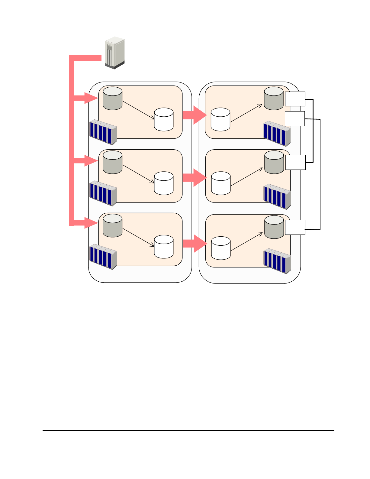
Write data
(with time stamp added)
Primary host
Primary site
Secondary site
Primary
data volume
Primary
data volume
Primary
data volume
Journal group 1 Journal group 1
Journal obtain
Journal copy
Master JNL VOL
Primary storage system 1
Journal group 2 Journal group 2
Master JNL VOL
Primary storage system 2
Journal group 3
Master JNL VOL
Primary storage system 3
Journal restore
according to time stamps
Restore JNL VOL
Secondary storage system 1
Restore JNL VOL
Secondary storage system 2
Journal group 3
Restore JNL VOL
Secondary storage system 3
Secondary
data volume
Secondary
data volume
Secondary
data volume
External
port
External
port
Target
port
Target
port
Figure 3-5 Using More Than One Primary and Secondary Storage
System for Remote Copy
When primary hosts write data to primary data volumes, the hosts add time
stamp to the data. Secondary storage systems check time stamps and then
restore data to data volumes in chronological order (older data are restored
earlier), so that data update sequence is maintained. For details on the timestamping function, see section
Chapter 3 Preparing for Universal Replicator z/OS Operations 3-17
Hitachi Universal Replicator for IBM /OS User’s Guide
Host I/O Time-Stamp.
Page 84

This manual uses the term "arbitration processing", which refers to execution
of the journal restore function based on time stamps in an attempt to maintain
data update sequence. When there is more than one secondary storage
system, one of the secondary storage systems controls the other secondary
storage systems, compares time stamps of data received by all the secondary
storage systems (including the local storage system), and then performs
arbitration processing. In this manual, the term "supervisor DKC" is used to
refer to the storage system that performs arbitration processing. Also, the
term "subordinate DKCs" is used to refer to the storage systems that are
controlled by the supervisor DKC and are targets of arbitration processing. In
the example in
DKC, and the secondary storage systems 2 and 3 are subordinate DKCs.
To perform arbitration processing, the supervisor DKC must be connected with
the subordinate DKCs. For details on connections between secondary storage
systems, see section
Figure 3-5, the secondary storage system 1 is the supervisor
Connections Between Secondary Storage Systems.
Basic Behavior When Using Multiple Primary and Secondary
Storage Systems
This section explains the basic behavior of URz under the following conditions:
• There are two primary storage systems and two secondary storage
systems.
• The status of all the URz pairs that use journal groups in the extended
consistency group is Duplex. Note: For details on extended consistency
groups, see section
Extended Consistency Groups.
• The primary host issues write requests to URz primary data volumes.
The following figure illustrates a URz operation when the above conditions are
satisfied,
3-18 Chapter 3 Preparing for Universal Replicator z/OS Operations
Hitachi Universal Replicator for IBM /OS User’s Guide
Page 85

(2)
(1)
(1)
Primary host (can add time stamps)
(2)
Primary data
Primary storage system 1
Primary data
volume
Primary storage system 2
Primary site
(3)
Master JNL VOL
(3)
Master JNL VOL
Secondary site
(5)
(4)
Restore JNL VOL
Secondary storage system 1
(4)
Restore JNL VOL
Secondary storage system 2
Secondary data
(5)
Secondary data
External
port
volume
Target
port
volume
Figure 3-6 A URz Operation W hen Two Primary Storage Systems and
Two Secondary Storage Systems are Used
The numbers in Figure 3-6 indicate the order that the processing is performed,
and correspond to the numbers in the numbered procedure below:
1. The primary host issues write requests to primary storage systems. Time
stamps are added to the data to be written.
2. The primary storage systems receive the write requests, and then notify
the primary host that primary data volumes are updated.
3. The URz journal obtain function stores data updated in primary data
volumes to master journal volumes as journal data. Time stamp
information added by the primary host will be added to journal data. Also,
sequence numbers indicating the order of writing will be added to journal
data.
4. The URz journal copy function copies journal data from the master journal
volumes to the corresponding restore journal volumes. This journal copy
operation will be performed asynchronously with the journal obtain
operation.
Chapter 3 Preparing for Universal Replicator z/OS Operations 3-19
Hitachi Universal Replicator for IBM /OS User’s Guide
Page 86

5. The secondary storage system 1 (i.e., the supervisor DKC) performs
arbitration processing. In other words, the secondary storage system 1
restores journal data of the secondary storage systems 1 and 2, based on
the time stamps and the sequence numbers added to the journal data, so
that consistency with the primary data volume is maintained.
The flow of the arbitration processing is as follows:
1. From journal data in restore journal groups registered in the extended
consistency group, the supervisor DKC collects time stamps of journal data
have not been restored.
2. The supervisor DKC compares the time stamps, and then selects the oldest
time stamp.
3. The supervisor DKC requests the subordinate DKCs to restore the journal
data that has the selected time stamp.
4. From journal data having the time stamp and earlier time stamps, the
subordinate DKCs restore all journal data that have not been restored, in
the order of the sequence numbers.
Hardware Configuration for Multiple Primary and Secondary
Storage Systems
This section explains hardware configuration when more than one primary and
secondary storage system are used.
It is recommended that Business Continuity Manager is installed on the host in
the primary and secondary sites. Storage Navigator PCs must be installed in
both of these sites. Also, storage system settings must be made so that
Business Continuity Manager can be used. For detailed information about
settings required for using volumes in a remote site, please refer to Business
Continuity Manager User's Guide.
Up to four primary storage systems and up to four secondary storage systems
can be used. For example, you can use four primary storage systems and four
secondary storage systems. Also, you can use two primary storage systems
and one secondary storage system.
The supervisor DKC and subordinate DKCs must be mutually connected in the
secondary site, so that arbitration processing can be performed. Also, remote
command devices must be created in the supervisor DKC. For details on
secondary storage systems connections and remote command devices, see the
next section and the Universal Volume Manager User's Guide.
3-20 Chapter 3 Preparing for Universal Replicator z/OS Operations
Hitachi Universal Replicator for IBM /OS User’s Guide
Page 87

Connections Between Secondary Storage Systems
If you use more than one primary storage system and more than one
secondary storage system, you must establish connections among the
secondary storage systems. To do this, you must configure paths and ports.
Also, you must create remote command devices by using Universal Volume
Manager.
The following figure is an example of connections among secondary storage
systems.
A’
Remote
command device
External
port
Target
port
A
Command device
Subordinate DKC
(Secondary storage system 2)
B’
Remote
command device
External
port
Supervisor DKC
(Secondary storage system 1)
Target
port
Command device
B
Subordinate DKC
(Secondary storage system 3)
Legend
:mapping
Figure 3-7 An Example of Connections among Secondary Storage
Systems
Based on the example in Figure 3-7, the subsections below explain
configuration of paths and ports, and creation of remote command devices.
Chapter 3 Preparing for Universal Replicator z/OS Operations 3-21
Hitachi Universal Replicator for IBM /OS User’s Guide
Page 88

Configuring Paths and Ports to Establish Connections among Secondary
Storage Systems
To establish connections among secondary storage systems, you must
configure external ports on the storage system that should be used as the
supervisor DKC. After that, you must configure paths between these external
ports and the target ports on the storage systems that should be used as
subordinate DKCs. In the example in
system 1 has external ports, each of which is connected with a target port on
the secondary storage system 2 and 3. For details on external ports, please
refer to the Universal Volume Manager User's Guide. For details on configuring
paths, please refer to the LUN Manager User's Guide.
By using fibre channel switches, target ports can also be connected to RCU
target ports on secondary storage systems. For details on RCU target ports,
see section
ports, see section
Initiator Ports and RCU Target Ports. For details on configuring
Configuring Port Attributes.
Figure 3-7, the secondary storage
Creating Remote Command Devices to Establish Connections among
Secondary Storage Systems
To establish connections among secondary storage systems, first you must
create a command device in each of the secondary storage systems. Next you
must create mapping between command devices in the supervisor DKC and
the subordinate DKCs. Thus, the supervisor DKC will be able to use command
devices in subordinate DKCs via remote command devices.
In the example of
secondary storage systems 2 and 3. Also, remote command devices are
created in the secondary storage system 1 (i.e., the supervisor DKC), and are
mapped to the secondary storage systems 2 and 3 (i.e., subordinate DKCs).
The emulation type of command devices and remote command devices must
be OPEN-V. For details on remote command devices, please refer to the
Universal Volume Manager User's Guide.
Caution: If maintenance operations are performed on remote command
devices (for example, the devices A' and B' in
connections among secondary storage systems, the pair will be suspended
according to a failure. To avoid this, you must remove all journal groups in the
extended consistency group that uses the remote command devices to be
maintained.
Figure 3-7, the command devices A and B are created in the
Figure 3-7) that are used for
3-22 Chapter 3 Preparing for Universal Replicator z/OS Operations
Hitachi Universal Replicator for IBM /OS User’s Guide
Page 89

Interoperability with Other Products and Functions
Some types of volumes used by non-URz functions can also be used as URz
data volumes and/or journal volumes.
volumes are also usable as URz volumes.
Table 3-11 Whether Non-URz Volumes Can Be Used as URz Volumes
Table 3-11 explains whether non-URz
Functions and Volumes Can the Volumes be
LUN Expansion (LUSE)
LUSE volume No. No. No.
ShadowImage for z/OS® (SIz)
S-VOL in Split status Yes. Yes. No.
S-VOL in Resync-R status No. No. No.
S-VOL that is also used as a
TCz P-VOL or TCz S-VOL
S-VOL (none of the above) Yes. Yes. No.
T-VOL in Split status Yes. No. No.
T-VOL (none of the above) No. No. No.
Reserved volume No. No. No.
Compatible FlashCopy®
S-VOL Yes. Yes. No.
T-VOL No. No. No.
Compatible FlashCopy® V2
S-VOL Yes. *1 No. No.
T-VOL No. No. No.
Concurrent Copy
Concurrent Copy volume Yes. No. No.
Compatible XRC
Compatible XRC volume No. No. No.
Volume Migration
Source volume
(when volume migration is in
progress)
Used as Primary
Data Volumes?
Yes. Yes. No.
Yes.
Note that volume
migration stops when
the source volume is
used as a primary
Can the Volumes be
Used as Secondary Data
Volumes?
Yes.
Note that volume
migration stops when the
source volume is used as
a secondary data volume.
Can the Volumes be
Used as Journal
Volumes?
No.
data volume.
Source volume
(after volume migration is
finished)
Reserved volume to which no
path is defined
TrueCopy for z/OS® (TCz)
Yes. Yes. No.
No. No. No
Chapter 3 Preparing for Universal Replicator z/OS Operations 3-23
Hitachi Universal Replicator for IBM /OS User’s Guide
Page 90

Functions and Volumes Can the Volumes be
Used as Primary
Data Volumes?
Can the Volumes be
Used as Secondary Data
Volumes?
Can the Volumes be
Used as Journal
Volumes?
M-VOL in Pending duplex
status
M-VOL in Duplex status Yes. *2 No. No.
M-VOL in Suspend status Yes. *2 No. *1 No.
M-VOL that is suspended due
to a failure
R-VOL in Pending status No. No. No.
R-VOL in Duplex status Yes. *2 No. No.
R-VOL in Suspend status Yes. *2 No. No.
R-VOL in Swapping status Yes. *2 No. *1 No.
R-VOL that is suspended due
to a failure
TrueCopy Asynchronous for z/OS®
TrueCopy Asynchronous for
®
z/OS
volume
Volume Retention Manager
Volume with Read/Write
attribute
Volume with Read Only
attribute
Volume with Protect attribute No. No. No.
Volume Security
Volume registered in a
security group
No. No. No.
Yes. *2 No. *1 No.
Yes. *2 No. No.
No. No. No.
Yes. Yes. Yes.
Yes. Yes. No.
Yes. Yes.
However, if the volume is
disabled for use as SVOL, the volume cannot
be used as a secondary
data volume.
No.
Cross-OS File Exchange
Volume usable by both
mainframe and open
systems
Cache Residency Manager
The volume on which Cache
Residency Manager setting
are made
Compatible PAV
Compatible PAV Yes. Yes. No.
Virtual LVI
Virtual LVI volume Yes. Yes. Yes.
No. No. No.
Yes. Yes. Yes.
Note*1: You cannot use the volume as a data volume of the URz pair for delta
resync operation.
3-24 Chapter 3 Preparing for Universal Replicator z/OS Operations
Hitachi Universal Replicator for IBM /OS User’s Guide
Page 91

Note*21: The volume can be used as a secondary data volume only when you
restore a URz pair or perform a Business Continuity Manager YKRESYNC
REVERSE operation. However, even in this case, you cannot use the volume
as the secondary data volume of the URz pair for delta resync operation.
Note*32: This is "No" if more than one primary storage systems and more
than one secondary storage system are used for remote copy (see section
Using Multiple Primary and Secondary Storage Systems).
Virtual LVI
You can perform Virtual LVI operations on primary and secondary data
volumes in URz pairs. If you need to perform Virtual LVI operations on a URz
primary data volume or secondary data volume, you must delete the pair first
to return the volume to Simplex status.
When creating a URz pair consisting of two Virtual LVI volumes, make sure
that the primary data volume and the secondary data volumes have the same
capacity.
Cache Residency Manager
You can perform Cache Residency Manager operations on URz primary data
volumes and secondary data volumes.
ShadowImage for z/OS®
URz and ShadowImage for z/OS® (SIz) can be used together in the same
storage system and on the same volumes to provide multiple copies of data at
the primary and/or secondary sites.
reporting for URz volumes, SIz volumes, and URz/SIz shared volumes.
3-13 shows the currency of the data on a shared URz/SIz volume based on
URz and SIz pair status.
• For shared URz/SIz volumes, the URz pair status is reported to the host if
you query the URz primary data volume or secondary data volume. To
obtain the SIz pair status, query the target volume (T-VOL) of the SIz pair.
• SIz supports multiple T-VOLs for each source volume (S-VOL). If you issue
a pair status query to a SIz S-VOL (e.g., pairdisplay), the status for only
one SIz pair is reported (the pair with the T-VOL with the lowest LDEV ID).
To obtain the pair status for the SIz pair(s) with the other T-VOL(s), you
must direct the host query to the specific S-VOL using the T-VOL’s LDEV ID
in the host command. The SIz remote console software displays the port,
TID, LUN, LDEV ID and SIz pair status of all T-VOLs associated with a
S-VOL.
Table 3-12 describes the host pair status
Table
Chapter 3 Preparing for Universal Replicator z/OS Operations 3-25
Hitachi Universal Replicator for IBM /OS User’s Guide
Page 92

Table 3-12 Host Pair Status Reporting for URz/SIz Shared Volumes
Number of
URz pairs
0 0 Simplex
0 1 SIz pair status
0 2 or more SIz pair status for the pair whose S-VOL has the lowest LDEV ID
1 0 URz pair status
1 1 URz pair status
1 2 or more URz pair status
Number of SIz
T-VOLs
Pair status reported by USP V
Table 3-13 Data Currency of a Shared URz/ SIz Volume
SIz pair status
URz pair
status
Pending
Duplex
Duplex Not current Not current Not current CURRENT Not current
Suspended Not current CURRENT CURRENT CURRENT CURRENT
Pending
Duplex
Not current Not current Not current CURRENT Not current
Duplex Split-
Pending
Split Resync Suspende
d
Not
current
Not
current
Not
current
Figure 3-8 through Figure 3-11 show the various URz/SIz configurations which
share volumes.
• URz/SIz configurations which share the URz primary data volume and SIz
S-VOL
Figure 3-8 shows an example of a URz primary data volume which is also
functioning as a SIz S-VOL. This configuration allows you to use SIz for onsite data backup in case of a URz failure, and to use URz to provide remote
backup of the SIz S-VOL in case of a SIz failure.
Primary
data
volume
S-VOL
MCU
Master journal
volume
SIz
Figure 3-8 Shared URz primary data volume and SIz S-VOL
URz
T-VOL
Secondary
data volume
Restore journal
volume
RCU
3-26 Chapter 3 Preparing for Universal Replicator z/OS Operations
Hitachi Universal Replicator for IBM /OS User’s Guide
Page 93

Business Continuity Manager allows you to set the starting time of backup
copy to journal groups. In the above configuration, if you set the starting time
of backup copy, the writes to the primary data volume up to that time will be
backed up to the secondary data volume. If the above configuration is used in
multiple journal volumes in multiple disk subsystems, you can set the same
starting time of backup copy to all the journal groups. If you do this operation,
the primary data volumes will be backed up across the multiple disk
subsystems at the same time.
• URz/SIz configurations which share the URz secondary data volume and
SIz P-VOL
Figure 3-9 shows an example of a URz secondary data volume which is also
functioning as a SIz S-VOL. This configuration allows you to use SIz to
provide multiple backup copies of a single URz primary data volume.
Primary data
volume
MCU
Master journal
volume
URz
Secondary
data volume
S-VOL
RCU
Restore journal
volume
SIz
T-VOL
Figure 3-9 Shared URz secondary data volume and SIz S-VOL
Caution: If you use a URz secondary data volume as an SIz S-VOL as
shown in
Figure 3-9, the write operation to the URz primary data volume
takes time. Especially, when the SIz pair is in the V-Split status, the write
operation to the URz primary data volume may takes extra time according
to the time for copying process of the SIz pair.
In addition, note that if the journal volume size is small, the URz pair may
be suspended by failure because of the shortage of the capacity of its
journal volume.
Business Continuity Manager allows you to set the starting time of backup
copy to journal groups. In the above configuration, if you set the starting
time of backup copy, the writes to the primary data volume up to that time
will be backed up to the secondary data volume. If the above configuration
is used in multiple journal volumes in multiple storage systems, you can
set the same starting time of backup copy to all the journal groups. If you
do this operation, the primary data volumes will be backed up across the
multiple storage systems at the same time.
• URz/SIz configuration which share the UR primary data volume and SIz S-
VOL, and UR secondary data volume and SIz S-VOL
Chapter 3 Preparing for Universal Replicator z/OS Operations 3-27
Hitachi Universal Replicator for IBM /OS User’s Guide
Page 94

Figure 3-10 combines the configurations shown in Figure 3-8 and Figure
j
3-9. Within a single URz pair, the primary data volume and secondary data
volume are both functioning as SIz S-VOLs, providing multiple copies at
the primary and secondary sites.
Primary data
volume
S-VOL
MCU
T-VOL
Master journal
volume
SIz
URz
Secondary
data volume
S-VOL
RCU
Restore
ournal volume
SIz
T-VOL
Figure 3-10 Shared URz primary data volume and SIz S-VOL, and URz
secondary data volume and SIz S-VOL
• URz/SIz configuration where a SIz T-VOL in Split status is used as
a URz primary data volume
In the following example, the SIz T-VOL in Split status is also functioning
as a URz primary data volume. This configuration allows URz to make a
remote backup copy of the SIz T-VOL.
SIz
URz
Primary data
volume
S-VOL in
Split statu s
T-VO L in
Split statu s
MCU
Master journal
volume
Secondary
data volume
Restore journal
volume
RCU
Figure 3-11 SIz T-VOL in Split Status Functioning as URz Primary
Data Volume
If a failure occurs and the SIz S-VOL is damaged in Figure 3-11, take the
following steps to copy data from the URz secondary data volume to the
SIz S-VOL so that data can be restored to the SIz S-VOL:
1. Execute the Business Continuity Manager YKDELETE command on the SIz
pair to release the pair (see
Figure 3-12).
2. Execute the Business Continuity Manager YKSUSPND REVERSE command
on the URz pair to suspend the pair. After that, execute the YKRESYNC
REVERSE command to reverse the copy direction and re-establish the pair
(see
Figure 3-13).
3-28 Chapter 3 Preparing for Universal Replicator z/OS Operations
Hitachi Universal Replicator for IBM /OS User’s Guide
Page 95

3. Execute the Business Continuity Manager YKSUSPND FORWARD
T
command on the URz pair to suspend the pair. After that, execute the
YKRESYNC FORWARD command to change the copy direction to the
original direction and re-establish the pair (see
Figure 3-14).
4. Execute the Business Continuity Manager YKSUSPND command on the
URz pair to suspend the pair (see
Figure 3-15).
5. Execute the Business Continuity Manager YKMAKE command on the SIz
pair to perform copying in the reverse direction (see
Figure 3-16).
6. Execute the Business Continuity Manager YKDELETE command on the SIz
pair to release the pair (see
Figure 3-17).
7. Execute the Business Continuity Manager YKMAKE command on the SIz
pair to perform copying in the original direction (see
Figure 3-18).
8. Execute the Business Continuity Manager YKSUSPND command on the SIz
pair to put the pair in Split status (see
Figure 3-19).
9. Execute the Business Continuity Manager YKRESYNC command on the
URz pair to resynchronize the pair (see
Figure 3-20).
S-VOL in
Split status
SIz
Primary data
volume
-VOL in
Split status
MCU
Master journal
volume
URz
Secondary
data volume
RCU
Figure 3-12 Restoring a SIz S-VOL - Step 1
Secondary data
volume
RCU
Restore journal
volume
URz
Primary data
volume
MCU
Figure 3-13 Restoring a SIz S-VOL - Step 2
Restore journal
volume
Master journal
volume
Chapter 3 Preparing for Universal Replicator z/OS Operations 3-29
Hitachi Universal Replicator for IBM /OS User’s Guide
Page 96
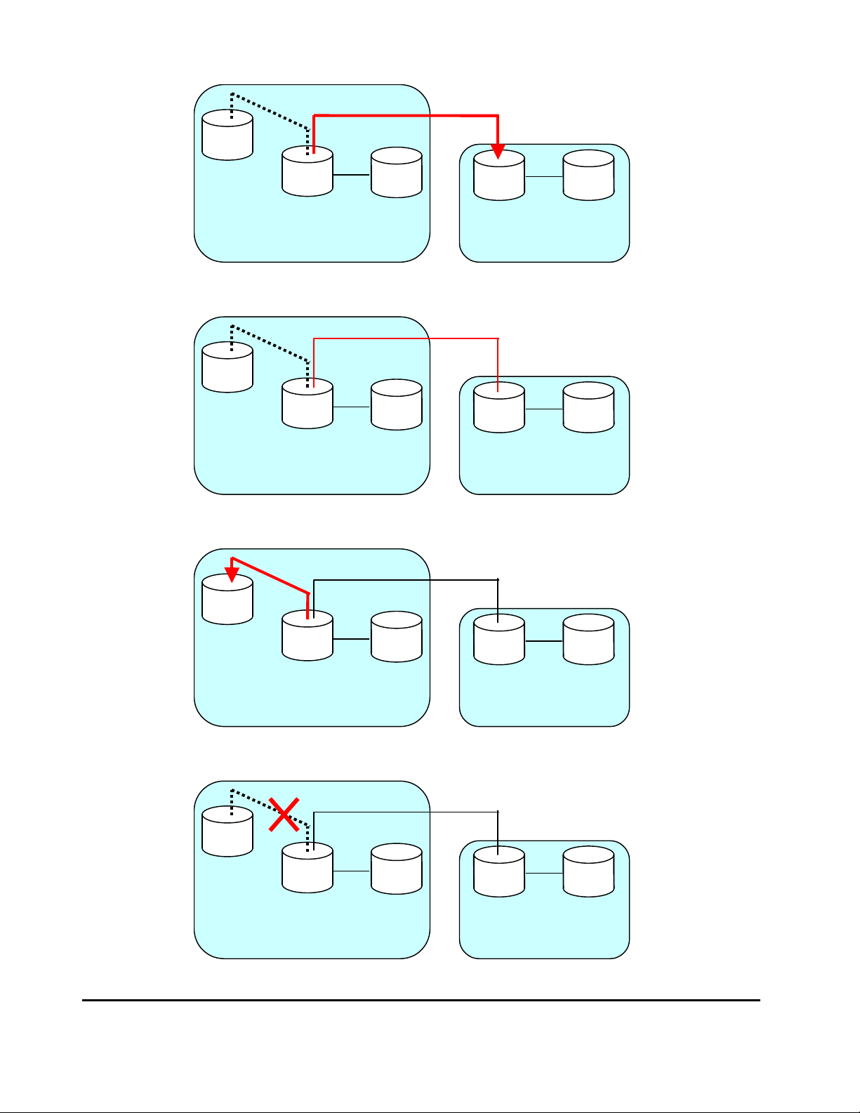
(
)
j
(
)
Primary data
volume
URz
MCU
Master journal
volume
Secondary
data volume
RCU
Figure 3-14 Restoring a SIz S-VOL - Step 3
URz
Primary data
volume
(suspended)
MCU
Master journal
volume
Secondary data
volume
suspended
RCU
Figure 3-15 Restoring a SIz S-VOL - Step 4
SIz
Primary data volume
(suspended)
URz
Restore journal
volume
Restore
ournal volume
T-VOL
S-VOL
Master journal
volume
MCU
Secondary
data volume
suspended
Restore journal
volume
RCU
Figure 3-16 Restoring a SIz S-VOL - Step 5
T-VOL
3-30 Chapter 3 Preparing for Universal Replicator z/OS Operations
SIz
Primary data volume
(suspended)
S-VOL
MCU
Master journal
volume
URz
Secondary
data volume
(suspended)
Restore journal
volume
RCU
Hitachi Universal Replicator for IBM /OS User’s Guide
Page 97

Figure 3-17 Restoring a SIz S-VOL - Step 6
(
)
T
T
S-VOL
SIz
Primary data volume
(suspended)
T-VOL
MCU
Master journal
volume
URz
Secondary
data volume
suspended
RCU
Figure 3-18 Restoring a SIz S-VOL - Step 7
S-VOL in
Split status
SIz
Primary data volume
(suspended)
-VOL in
Split status
MCU
Master journal
volume
URz
Secondary
data volume
(suspended)
RCU
Figure 3-19 Restoring a SIz S-VOL - Step 8
Restore journal
volume
Restore journal
volume
S-VOL in
Split status
SIz
Primary data
volume
-VOL in
Split status
MCU
Master journal
volume
URz
Secondary
data volume
Restore journal
volume
RCU
Figure 3-20 Restoring a SIz S-VOL - Step 9
Chapter 3 Preparing for Universal Replicator z/OS Operations 3-31
Hitachi Universal Replicator for IBM /OS User’s Guide
Page 98
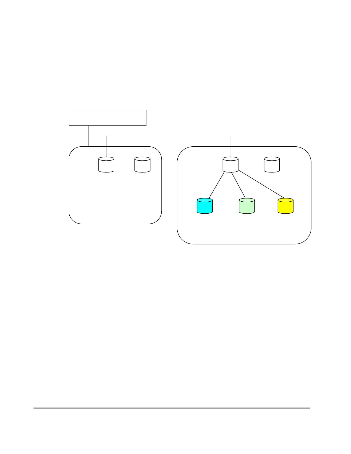
Using At-Time Split Function When Combining URz with
®
ShadowImage for z/OS
When URz secondary data volume (S-VOL) is specified as S-VOL of SIz pair,
you can specify the time of backup copy operation for URz by using the AtTime Split function of the Business Continuity Manager. This backup copy
operation is called the split operation. The time when split operation is
executed is called the split time.
Business Continuity Manager
(SIz)
URz
Primary data
volume
Master journal
volume
MCU
- Secondary data
volume
- SIz S-VOL
Execute split
operation at
10:00
SIz T-VOL SIz T-VOL
Back up copy at
10:00
Execute split
operation at 11:00
Back up copy at
11:00
Restore journal volume
Execute split
operation at 12:00
SIz T-VOL
Back up copy at
12:00
RCU
Figure 3-21 Overview of Split Operation
The At-Time Split function has the following restrictions when URz and
ShadowImage for z/OS
®
are used in conjunction:
• The At-Time Split function can be executed by Business Continuity
Manager, but cannot be executed by Storage Navigator.
• You can execute split operations on SIz pairs that belong to ShadowImage
for z/OS® consistency groups.
• You can apply one split operation to one ShadowImage for z/OS®
consistency group.
• You can apply up to three split operations to one journal group (equivalent
to three ShadowImage for z/OS® consistency groups).
• One SIz S-VOL can be paired with up to three SIz T-VOLs. This enables you
to create a maximum of three generations of backup data.
3-32 Chapter 3 Preparing for Universal Replicator z/OS Operations
Hitachi Universal Replicator for IBM /OS User’s Guide
Page 99

The procedure to use the At-Time Split function when you combine URz with
ShadowImage for z/OS
®
is as follows. The following steps enable you to make
backup copy at a specified time without suspending URz pairs.
1. Specify the split time by using Business Continuity Manager.
2. Among the URz restore journals, the journal data created before the split
time is restored to URz S-VOLs (SIz S-VOLs).
3. When URz detects the journal data from the restore journal which has the
time stamp later than the split time, restore operations will be suspended.
After that, split operations will be executed on SIz pairs which are in
conjunction with URz S-VOL.
4. After SIz has completed the split operations, URz will resume the
suspended restore operation of the restore journal.
Caution: If you use the At-Time Split function when combining URz with SIz,
mind the following:
– Make sure that all of the URz S-VOLs are paired with SIz volumes. Also,
all of the SIz pairs in conjunction with URz S-VOLs must belong to the
same ShadowImage for z/OS
are not paired with SIz volumes, or if SIz pairs in conjunction with URz
S-VOL belong to different ShadowImage for z/OS
®
consistency group. If all the URz S-VOLs
®
consistency groups,
consistent backup copy operations cannot be executed.
– When you execute split operation, the URz pair status must be duplex,
and the SIz pair status must be either duplex or pending. If the status
of the URz pair or the SIz pair is suspended due to a failure, the journal
data which was created before the split time may not be restored to the
SIz T-VOL after the split operation has been completed.
– The split time and the actual starting time of the split operation are not
necessarily the same. The starting time of the split operation will delay
depending on the amount of journal data stored in the journal volume
at the split time. For example, if journal data that needs one hour to be
completely restored is stored at the split time, the starting time of the
split operation will delay for one hour.
– Even if the specified timeout period has passed from the split time,
journal data with the time stamp later than the split time may not be
detected due to some reason such as a lot of journal data stored in the
journal volume. If the journal data with such a time stamp cannot
detected, the split operation of SIz pair will be executed after the
specified timeout period. Since the time out value is variable, please set
the value according to your environment. The default time out value is
6 hours. For a guide to set the time out value, please refer to the
Guideline for the Timeout Menu Setting When Using At-Time Split
Function at Combining Universal Replicator with ShadowImage. For
details on how to specify a timeout value, please refer to the Business
Continuity Manager™ User's Guide.
Note: If you use the At-Time Split function when combining URz with
SIz, note the following:
Chapter 3 Preparing for Universal Replicator z/OS Operations 3-33
Hitachi Universal Replicator for IBM /OS User’s Guide
Page 100

– The specified split time is enabled even after the split operation has
been executed on SIz pair. When you execute split operation again on
ShadowImage for z/OS® consistency group that has been split before,
specify the split time after deleting the split time registered before.
– In cascading configuration of URz and TrueCopy for z/OS®, the At-Time
Split function cannot be used for SIz pairs in conjunction with URz SVOLs.
– In Multi-target configuration of URz and TrueCopy for z/OS®, when the
At-Time Split function is used for SIz pairs in conjunction with URz SVOLs, please mind the following: when URz and TrueCopy for z/OS®
are configured in a cascading configuration during disaster recovery
operation, the At-Time Split function cannot be used.
– The specified split time will be reset by executing PS OFF of RCU.
– You cannot execute Reverse Resync of URz when split time is already
specified. Please execute Reverse Resync after you delete all the
specified split time of SIz pairs in conjunction with the restore journal
group. For details on Reverse Resync, please refer to the Business
Continuity Manager™ User's Guide.
– When split time is set to ShadowImage for z/OS
®
consistency group,
you cannot perform Add Pair operation, Pair Resync operation, or Split
Pair operation from the Business Continuity Manager. If you need to
execute Add Pair operation, Pair Resync operation, or Split Pair
operation, please delete the split time in advance. When split time is set
to ShadowImage for z/OS
®
consistency group, pairs can be deleted. If
you delete the following pairs, the specified split time will be deleted:
– Delete all the SIz pairs belonging to the ShadowImage for z/OS
®
consistency group.
– Delete all the URz pairs belonging to the URz restore journal group.
TCz Synchronous (3DC Cascading Configuration)
The USP V storage system provides the function to combine URz and TCz
Synchronous. This combination is intended to ensure that the response time
against host I/Os is comparable, regardless of whether the distance between
the primary and the secondary sites are short or long. This combination is also
intended to ensure that the secondary site stores data that has been stored in
the primary site even when a failure occurs in the primary site. These
intentions will be fulfilled if remote copy operations are performed using
cascading connections and a three data center (3DC) configuration; in a 3DC
configuration, an intermediate site is located between the primary and
secondary sites.
3-34 Chapter 3 Preparing for Universal Replicator z/OS Operations
Hitachi Universal Replicator for IBM /OS User’s Guide
 Loading...