

Page 1
S
Hit achi Universal Storage Platform VM
Installation Planning Guide
F
ASTFIND
L
INK
Document Organization
Product Version
Getting Help
Contents
MK-97RD6679-00
Page 2

Copyright © 2007 Hitachi Data Systems
Corporation, ALL RIGHTS RESERVED
Notice:
No part of this publication may be
reproduced or transmitted in any form or by
any means, electronic or mechanical,
including photocopying and recording, or
stored in a database or retrieval system for
any purpose without the express written
permission of Hitachi Data Systems
Corporation (hereinafter referred to as
“Hitachi Data Systems”).
Hitachi Data Systems reserves the right to
make changes to this document at any time
without notice and assumes no responsibility
for its use. Hitachi Data Systems products
and services can only be ordered under the
terms and conditions of Hitachi Data Systems’
applicable agreements. All of the features
described in this document may not be
currently available. Refer to the most recent
product announcement or contact your local
Hitachi Data Systems sales office for
information on feature and product
availability.
This document contains the most current
information available at the time of
publication. When new and/or revised
information becomes available, this entire
document will be updated and distributed to
all registered users.
Hitachi Data Systems is a registered
trademark and service mark of Hitachi, Ltd.,
and the Hitachi Data Systems design mark is
a trademark and service mark of Hitachi, Ltd.
Dynamic Provisioning, Hi-Track,
ShadowImage, TrueCopy, and Universal Star
Network are registered trademarks or
trademarks of Hitachi Data Systems.
All other brand or product names are or may
be trademarks or service marks of and are
used to identify products or services of their
respective owners.
ii
Hitachi Universal Storage Platform VM Installation Planning Guide
Page 3

Contents
Preface................................................................................................... v
Safety and Environmental Notices.........................................................................vi
Intended Audience..............................................................................................vi
Product Version.................................................................................................. vii
Document Revision Level.................................................................................... vii
Changes in this Revision..................................................................................... vii
Document Organization ...................................................................................... vii
Referenced Documents.......................................................................................vii
Document Conventions...................................................................................... viii
Convention for Storage Capacity Values.............................................................. viii
Getting Help .......................................................................................................ix
Comments..........................................................................................................ix
Planning for Installation........................................................................ 1-1
Responsibilities .................................................................................................1-2
Customer Responsibilities............................................................................1-2
Hitachi Data Systems Responsibilities...........................................................1-2
Installation Planning Tasks.................................................................................1-3
Installation Planning Checklist............................................................................1-4
Installation Requirements...................................................................... 2-1
Safety Requirements .........................................................................................2-2
Delivery Requirements .......................................................................................2-3
Storage Requirements.......................................................................................2-4
Facilities Requirements......................................................................................2-5
Physical Specifications and Requirements............................................................2-6
Dimensions and Weight...............................................................................2-7
Service Clearance, Floor Cutout, and Floor Load Rating................................2-10
Contents iii
Hitachi Universal Storage Platform VM Installation Planning Guide
Page 4

Power Specifications and Requirements............................................................ 2-13
Power Specifications and Power Supplies................................................... 2-13
Breaker Configurations............................................................................. 2-15
Power Connection.................................................................................... 2-16
Input Voltage and Input Frequency........................................................... 2-18
Circuit Breakers and Plugs ........................................................................ 2-18
Environmental Specifications and Requirements................................................ 2-19
Temperature, Humidity, and Altitude ......................................................... 2-19
Heat Output, Power Consumption, and Air Flow ......................................... 2-20
Loudness ................................................................................................ 2-21
Vibration and Shock................................................................................. 2-21
Operational Requirements............................................................................... 2-22
Units and Unit Conversions ................................................................... A-1
Acronyms and Abbreviations
iv Contents
Hitachi Universal Storage Platform VM Installation Planning Guide
Page 5

Preface
This document provides installation and configuration planning information for
the Hitachi Universal Storage Platform VM (USP VM) storage system.
Please read this document carefully to understand the installation
requirements for the Universal Storage Platform VM, and maintain a copy for
reference.
This preface includes the following information:
Safety and Environmental Notices
Intended Audience
Product Version
Document Revision Level
Changes in this Revision
Document Organization
Referenced Documents
Document Conventions
Convention for Storage Capacity Values
Getting Help
Comments
Notice: The use of the Hitachi Universal Storage Platform VM and all other
Hitachi Data Systems products is governed by the terms of your agreement(s)
with Hitachi Data Systems.
Preface v
Hitachi Universal Storage Platform VM Installation Planning Guide
Page 6
Safety and Environmental Notices
Federal Communications Commission (FCC) Statement
This equipment has been tested and found to comply with the limits for a Class
A digital device, pursuant to part 15 of the FCC Rules. These limits are
designed to provide reasonable protection against harmful interference when
the equipment is operated in a commercial environment. This equipment
generates, uses, and can radiate radio frequency energy and, if not installed
and used in accordance with the instruction manual, may cause harmful
interference to radio communications. Operation of this equipment in a
residential area is likely to cause harmful interference in which case the user
will be required to correct the interference at his own expense.
“EINE LEICHT ZUGÄNGLICHE TRENN-VORRICHTUNG, MIT EINER KONTAKT-
ÖFFNUNGSWEITE VON MINDESTENS 3mm IST IN DER UNMITTELBAREN NÄHE
DER VERBRAUCHERANLAGE ANZUORDNEN (4-POLIGE ABSCHALTUNG).”
Maschinenlärminformationsverordnung 3. GSGV, 18.01.1991: Der
höchste Schalldruckpegel beträgt 70 db(A) oder weniger gemäß ISO 7779.
CLASS 1 LASER PRODUCT
CLASS 1 LASER PRODUCT
LASER KLASSE 1
WARNING: This is a Class A product. In a domestic environment this product
may cause radio interference in which case the user may be required to take
adequate measures.
WARNUNG: Dies ist ein Produkt der Klasse A. In nichtgewerblichen
Umgebungen können von dem Gerät Funkstörungen ausgehen, zu deren
Beseitigung vom Benutzer geeignete Maßnahmen zu ergreifen sind.
Intended Audience
This document is intended for system administrators, Hitachi Data Systems
representatives, and authorized service providers who are involved in
installation planning for the Hitachi Universal Storage Platform VM.
This document assumes the following:
• The user has a background in hardware installation for computer systems.
• The user is familiar with the location where the Universal Storage Platform
VM will be installed, including knowledge of physical characteristics, power
systems and specifications, environmental specifications.
vi Preface
Hitachi Universal Storage Platform VM Installation Planning Guide
Page 7
Product Version
This document revision applies to Universal Storage Platform VM microcode
60-02-0x and higher.
Document Revision Level
Revision Date Description
MK-97RD6679-00 November 2007 Initial release, supersedes and replaces MK-97RD6079
Changes in this Revision
• Added information on the 750-GB hard disk drive (Table 2-2, Table 2-8).
Document Organization
The following table provides an overview of the contents and organization of
this document. Click the
The first page of each chapter provides links to the sections in that chapter.
chapter title in the left column to go to that chapter.
Chapter Description
Planning for Installation
Installation Requirements
Units and Unit Conversions
Acronyms and Abbreviations Defines the acronyms and abbreviations used in this document.
Referenced Documents
• Hitachi Universal Storage Platform V/VM User and Reference Guide,
MK-96RD635
Describes the responsibilities and tasks involved in installation planning
for the Universal Storage Platform VM. Provides the Installation
Planning Checklist for the Universal Storage Platform VM.
Provides the installation requirements for the Universal Storage
Platform VM.
Provides conversions for standard (U.S.) and metric units of meas ure
associated with the Universal Storage Platform VM.
Preface vii
Hitachi Universal Storage Platform VM Installation Planning Guide
Page 8
Document Conventions
The term “Universal Storage Platform VM” refers to all models of the Universal
Storage Platform VM storage system, unless otherwise noted.
This document uses the following icons to draw attention to information:
Icon Meaning Description
Note Calls attention to important and/or additional information.
Tip
Caution
WARNING
DANGER
ELECTRIC SHOCK
HAZARD!
ESD Sensitive
Provides helpful information, guidelines, or suggestions for performing
tasks more effectively.
Warns the user of adverse conditions and/or consequences (e.g.,
disruptive operations).
Warns the user of severe conditions and/or consequences (e.g.,
destructive operations).
Provides information about how to avoid physical injury to yourself and
others.
Warns the user of electric shock hazard. Failure to take appropriate
precautions (e.g., do not touch) could result in serious injury.
Warns the user that the hardware is sensiti ve to electrostatic discharge
(ESD). Failure to take appropriate precautions (e.g., grounded wrist
strap) could result in damage to the hardware.
Convention for Storage Capacity Values
Physical storage capacity values (e.g., disk drive capacity) are calculated
based on the following values:
1 KB = 1,000 bytes
1 MB = 1,000
1 GB = 1,000
1 TB = 1,000
1 PB = 1,000
Logical storage capacity values (e.g., logical device capacity) are calculated
based on the following values:
1 KB = 1,024 bytes
1 MB = 1,024
1 GB = 1,024
1 TB = 1,024
1 PB = 1,024
1 block = 512 bytes
2
bytes
3
bytes
4
bytes
5
bytes
2
bytes
3
bytes
4
bytes
5
bytes
viii Preface
Hitachi Universal Storage Platform VM Installation Planning Guide
Page 9

Getting Help
If you need to call the Hitachi Data Systems Support Center, make sure to
provide as much information about the problem as possible, including:
• The circumstances surrounding the error or failure.
• The exact content of any error message(s) displayed on the host
system(s).
• The service information messages (SIMs), including reference codes and
severity levels, displayed by Storage Navigator.
The Hitachi Data Systems customer support staff is available 24 hours a day,
seven days a week. If you need technical support, please call:
• United States: (800) 446-0744
• Outside the United States: (858) 547-4526
Comments
Please send us your comments on this document. Make sure to include the
document title, number, and revision. Please refer to specific section(s) and
paragraph(s) whenever possible.
• E-mail: doc.comments@hds.com
• Fax: 858-695-1186
• Mail:
Technical Writing, M/S 35-10
Hitachi Data Systems
10277 Scripps Ranch Blvd.
San Diego, CA 92131
Thank you! (All comments become the property of Hitachi Data Systems
Corporation.)
Preface ix
Hitachi Universal Storage Platform VM Installation Planning Guide
Page 10

x Preface
Hitachi Universal Storage Platform VM Installation Planning Guide
Page 11

1
Planning for Installation
This chapter describes the requirements and procedures for planning to install
the Universal Storage Platform VM.
Responsibilities
Installation Planning Tasks
Installation Planning Checklist
Planning for Installation 1-1
Hitachi Universal Storage Platform VM Installation Planning Guide
Page 12

Responsibilities
The responsibilities for installation planning are shared by the customer and
the Hitachi Data Systems account team. The required installation planning
tasks must be scheduled and completed to ensure successful and efficient
installation of the Universal Storage Platform VM.
Customer Responsibilities
You are responsible for:
• Performing the installation planning tasks described in this document.
• Verifying that all installation requirements have been met by completing
the Installation Planning Checklist in this document.
• Providing the customer-supplied hardware that is required for storage
system installation (e.g., electrical connectors and receptacles).
• Observing all applicable safety requirements at all times.
Hitachi Data Systems Responsibilities
Your Hitachi Data Systems account team will assist you throughout the
installation planning process.
The Hitachi Data Systems account team is responsible for:
• Assisting you as needed during the installation planning process for your
specific site and operational configuration.
• Coordinating Hitachi Data Systems resources to ensure smooth installation
and configuration of the Universal Storage Platform VM.
1-2 Planning for Installation
Hitachi Universal Storage Platform VM Installation Planning Guide
Page 13

Installation Planning Tasks
The customer is responsible for performing the following tasks, with assistance
as needed from the Hitachi Data Systems account team, to prepare for
installation of the Universal Storage Platform VM storage system:
1.
Read this document carefully to understand the installation requirements
for the Universal Storage Platform VM. You will use the information in this
document to determine the specific requirements for your installation.
2.
Review the User and Reference Guide (MK-96RD635) to familiarize
yourself with the components, features, and functions of the Universal
Storage Platform VM storage system.
3.
Complete the Checklist in this document before equipment delivery to
verify that all installation requirements are met.
If any requirements are not met, make the changes required to meet the
requirements. Be sure to allow enough time to complete the required
changes, so that the site is ready when the equipment arrives.
4.
Provide the customer-supplied hardware that is required for
installation and configuration (e.g., connectors, receptacles).
5.
Work with your Hitachi Data Systems account team during the
installation planning process for the Universal Storage Platform VM.
Planning for Installation 1-3
Hitachi Universal Storage Platform VM Installation Planning Guide
Page 14
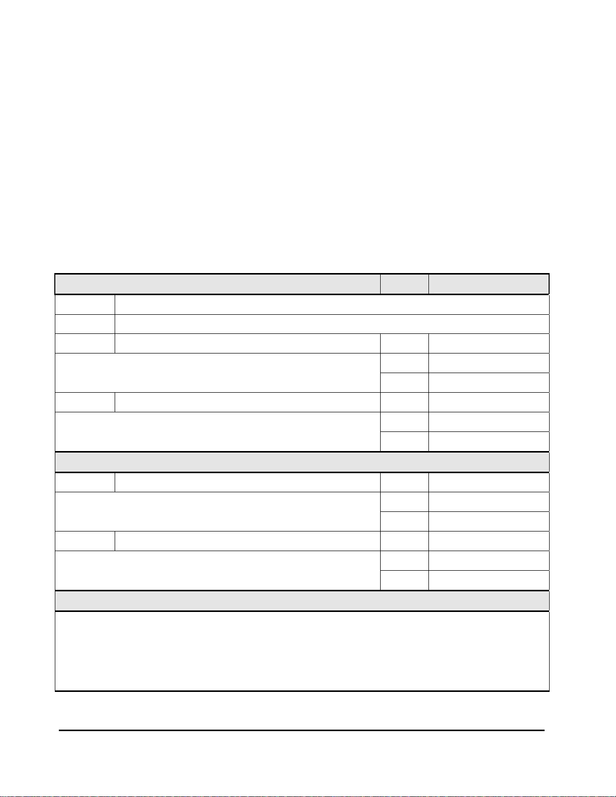
Installation Planning Checklist
Complete the checklist below (online or hardcopy) to verify that all installation
requirements for the Universal Storage Platform VM have been met.
Successful completion of this checklist (
ensure smooth and efficient installation of the Universal Storage Platform VM.
Definition of terms:
Data center: The room at the customer site in which the Universal
Storage Platform VM will be installed.
Equipment: The hardware delivered to the customer site that includes the
Universal Storage Platform VM storage system components and rack(s).
Location: The specific location in the data center (area or “footprint” on
the floor) where the Universal Storage Platform VM will be installed.
Yes is checked for all entries) will
Customer Information Date:
Company:
Address:
Contact: Phone:
Mobile:
E-mail:
Contact: Phone:
Mobile:
E-mail:
Hitachi Data Systems Information
Contact: Phone:
Mobile:
E-mail:
Contact: Phone:
Mobile:
Notes
1-4 Planning for Installation
Hitachi Universal Storage Platform VM Installation Planning Guide
E-mail:
Page 15

Installation Planning Checklist
Yes No
Safety
Is the data center equipped to protect equipment from f ire ?
Is the data center free of hazards (e.g., cables that obstruct access)?
Delivery
Is the receiving area adequate for equipment delivery and unloading? (overall height: 84 in, 2.134 m)
Does the equipment fit through doors, halls, elevators, and stairs?
Do the floors, elevators, stairs, and ramps support the weight of the equipment?
Storage
If the equipment will be stored after delivery and prior to installation, does the storage location
meet the environmental requirements for the USP VM?
Facilities
Is the data center fully operational (e.g., power, air conditioning, cabling, fire protection system)?
Does the data center have a tiled raised floor?
Does the data center provide adequate protection from ESD?
Does the data center provide adequate protection from electrical/radio frequency interference?
Does the data center provide adequate protection from dust, pollution, and particulate contamination?
Does the data center provide adequate acoustic insulation for operation of the USP VM?
Is the customer-supplied hardware (e.g., connectors, receptacles, cables) ready for the installation?
Physical
Does the location meet the requirements for service clearance and cable routing (e.g., floor cutouts)?
Does the location meet the requirements for floor load rating?
Power
Does the data center meet the AC input power requirements?
Does the data center meet the circuit breaker and plug requirements?
Does the data center meet the requirements for connection to UPS?
Environmental
Does the data center meet the requirements for temp erature?
Does the data center meet the requirements for humidity?
Does the data center meet the requirements for altitude?
Does the data center meet the requirements for air flow?
Does the data center meet the requirements for vibration and shock?
Operational
Does the data center provide a LAN (or phone line) for Hi-Track®?
Does the data center provide a LAN for Storage Navigator?
Does the location meet the cable length requirements for the front-end directors?
Does the location meet the requireme nts for attaching external storage to the USP VM?
Planning for Installation 1-5
Hitachi Universal Storage Platform VM Installation Planning Guide
Page 16

1-6 Planning for Installation
Hitachi Universal Storage Platform VM Installation Planning Guide
Page 17

2
Installation Requirements
This chapter provides the installation requirements for the Universal Storage
Platform VM storage system.
Safety Requirements
Delivery Requirements
Storage Requirements
Facilities Requirements
Physical Specifications and Requirements
Power Specifications and Requirements
Environmental Specifications and Requirements
Operational Requirements
Note: The general information in this chapter is provided to assist in
installation planning and may not be complete. The installation and
maintenance documents used by Hitachi Data Systems personnel (e.g.,
Maintenance Manual) contain complete specifications. The exact electrical
power interfaces and requirements for each site must be determined and
verified to meet the applicable local regulations.
Installation Requirements 2-1
Hitachi Universal Storage Platform VM Installation Planning Guide
Page 18

Safety Requirements
The safety requirements for Universal Storage Platform VM installation are:
• Safety regulations: The data center must comply with all applicable
safety regulations, standards, and requirements.
• Fire protection: The data center must have an operational fire protection
system.
• Hazards: The data center must be free of hazards (e.g., cables on the
floor that obstruct access).
Observe the following general safety requirements:
• Cabling:
– Do not obstruct walkways when routing cables.
– Do not place heavy materials on cables.
– Do not place cables near any possible source of heat.
• Warning labels: Obey all warning labels. When warning labels become
dirty or start peeling off, replace them.
• Authorized personnel: Allow only qualified and authorized personnel
(e.g., certified electrician) to perform tasks that may be hazardous to
persons and/or equipment.
2-2 Installation Requirements
Hitachi Universal Storage Platform VM Installation Planning Guide
Page 19

Delivery Requirements
The customer site must accommodate the delivery and movement of the
equipment to the installation location in the data center.
The delivery requirements for Universal Storage Platform VM installation are:
• Dimensions: The loading bay, hallways, doors, elevators, and stairs must
be large enough to allow the delivered equipment to be moved to the
installation location.
The shipping crate dimensions are:
Height: 84 inches (2.134 meters) (overall height including palette)
Width: 42 inches (1066.8 mm)
Depth: 55 inches (1397 mm)
See
Service Clearance, Floor Cutout, and Floor Load Rating for the
dimensions of the USP VM product (uncrated and unpacked).
See
Dimensions and Weight for the dimensions of the USP VM components.
• Weight: The floors, elevators, stairs, and ramps must be able to support
the weight of the delivered equipment as it is moved to the installation
location. Spreader plates may be required to distribute the load and/or
protect the floor as the equipment is moved to the installation location.
The weight of the delivered equipment depends on the storage system
configuration. The weight for a maximally configured storage system could
reach 1600 or 1700 pounds (726 to 771 kilograms).
See
Dimensions and Weight for the weight specifications for the Universal
Storage Platform VM components.
Installation Requirements 2-3
Hitachi Universal Storage Platform VM Installation Planning Guide
Page 20

Storage Requirements
If the delivered equipment needs to be stored after delivery and prior to
installation, the storage location must meet the environmental requirements
for the Universal Storage Platform VM (see
Table 2-1 Environmental Specifications for Storage
Shipping & Storage*
Parameter Low High
Temperature °F (°C) 5 (-25) 140 (60)
Relative Humidity (%)
Max. Wet Bulb °F (°C) 84 (29)
Temperature Deviation °F/hour (°C/hour) 36 (20)
* For storage, the equipment should be packed with factory packing.
*4
Table 2-1).
5 – 95
2-4 Installation Requirements
Hitachi Universal Storage Platform VM Installation Planning Guide
Page 21

Facilities Requirements
The customer site must meet the following facilities requirements:
• General: The data center must be fully operational (e.g., power, air
conditioning, cabling, fire protection system).
• Floor: The data center must have a tiled raised floor.
• ESD: The data center must provide adequate protection from electrostatic
discharge (ESD).
• Electrical interference: The data center must provide adequate
protection from electrical/radio frequency interference.
• Dust, pollution, and particulate contamination: The data center must
provide adequate protection from dust, pollution, and particulate
contamination.
• Acoustics: The data center must provide adequate acoustic insulation for
operation of the Universal Storage Platform VM.
• Customer-supplied hardware: The customer-supplied hardware (e.g.,
connectors, receptacles) must be available and ready for installation of the
Universal Storage Platform VM.
Installation Requirements 2-5
Hitachi Universal Storage Platform VM Installation Planning Guide
Page 22

Physical Specifications and Requirements
A
Figure 2-1 shows a physical overview of the Universal Storage Platform VM.
The physical specifications and requirements for the USP VM include:
• Dimensions and Weight
• Service Clearance, Floor Cutout, and Floor Load Rating
Disk Chassis
(DKU-R1)
Disk Chassis
(DKU-R0)
dditional
SVP/Battery
Chassis
Operator Panel
Disk Controller
(DKC)
12U
12U
2U
10U
Primary Rack
Secondary Rack
Disk Chassis
(DKU-R3)
Disk Chassis
(DKU-R2)
Figure 2-1 Physical Overview of the Universal Storage Platform VM
2-6 Installation Requirements
Hitachi Universal Storage Platform VM Installation Planning Guide
Page 23

Dimensions and Weight
T
Figure 2-2 shows the dimensions of the single-rack configuration. Figure 2-3
shows the dimensions of the twin-rack configuration.
dimension and weight specifications for the Universal Storage Platform VM
components.
OP VIEW
1046 mm
FRONT VIEW
Table 2-2 lists the
601 mm
REAR VIEW
2001 mm
Figure 2-2 Physical Dimensions: Single-Rack Configuration
Installation Requirements 2-7
Hitachi Universal Storage Platform VM Installation Planning Guide
Page 24

TOP VIEW
1046 mm
FRONT VIE W
2001 mm
601 mm601 mm
TBD
Figure 2-3 Physical Dimensions: Twin-Rack Configuration
2-8 Installation Requirements
Hitachi Universal Storage Platform VM Installation Planning Guide
Page 25

Table 2-2 Component Specifications: Weight and Dimension
Dimension (mm)
Model Number Weight (kg) Width Depth Height
DKC615I-5 70 445 800 438
DKC-F615I-B2 80.5 445 647 522
DKC-F615I-SBX 13 445 800 84
DKC-F615I-LGAB 11 — — —
DKC-F615I-PLUC 2.0 — — —
DKC-F615I-PHUC 4.0 — — —
DKC-F615I-PLEC 1.5 — — —
DKC-F615I-PHEC 2.5 — — —
DKC-F615I-UC0 3.2 — — —
DKC-F615I-UC1 2.1 — — —
DKC-F615I-EXC0 6.2 — — —
DKC-F615I-SX 1.2 — — —
DKC-F615I-S4GQ 0.08 — — —
DKC-F615I-DKA 2.6 — — —
DKC-F615I-CX 2.2 — — —
DKC-F615I-C4G 0.08 — — —
DKC-F615I-C8G 0.08 — — —
DKC-F615I-8S 2.7 — — —
DKC-F615I-8MFS 3.0 — — —
DKC-F615I-8MFL 3.0 — — —
DKC-F615I-8FS 2.8 — — —
DKC-F615I-16FS 3.0 — — —
DKC-F615I-1FL 0.02 — — —
DKC-F615I-1FS 0.02 — — —
DKC-F615I-SVP 4.1 — — —
DKC-F615I-MDM 0.07 — — —
DKC-F615I-72KS 0.9 — — —
DKC-F615I-146KS 0.9 — — —
DKC-F605I-300KS 0.9 — — —
DKC-F605I-0R7HS 0.9 — — —
Installation Requirements 2-9
Hitachi Universal Storage Platform VM Installation Planning Guide
Page 26

Service Clearance, Floor Cutout, and Floor Load Rating
g
This section specifies the service clearance requirements (a + b) for the
Universal Storage Platform VM storage system, based on the floor load rating
and the clearance (c), and the required floor cutouts for cabling.
• Figure 2-4 shows the service clearance and floor cutout requirements for
the single-rack configuration.
clearance requirements for this configuration.
• Figure 2-5 shows the service clearance and floor cutout requirements for
the twin-rack configuration.
clearance requirements for this configuration.
Notes:
• For safe and efficient maintenance operations, clearance (c) should be
made as large as possible.
• Actual clearances for installation should be determined after consultin
the site/facilities manager, as the clearances could vary depending on the
building conditions.
Table 2-3 Floor Load Rating and Clearances: Single Rack
Table 2-3 shows the floor load rating and
Table 2-4 shows the floor load rating and
with
Floor Load Rating
500 (102.4) 0.2 0.2 0.2 0.2 0.2
450 (92.2) 0.2 0.2 0.2 0.2 0.2
400 (81.9) 0.2 0.2 0.2 0.2 0.2
350 (71.7) 0.3 0.2 0.2 0.2 0.2
300 (61.4) 0.6 0.4 0.3 0.2 0.2
kg/m2 (lb/ft2)
C=0 C=0.2 C=0.4 C=0.6 C=1.0
Required Clearance (a+b) m
Clearance (c) m
Table 2-4 Floor Load Rating and Clearances: Two Racks
Floor Load Rating
500 (102.4) 0.2 0.2 0.2 0.2 0.2
450 (92.2) 0.2 0.2 0.2 0.2 0.2
400 (81.9) 0.2 0.2 0.2 0.2 0.2
350 (71.7) 0.4 0.3 0.2 0.2 0.2
300 (61.4) 0.8 0.6 0.5 0.4 0.2
kg/m2 (lb/ft2)
C=0 C=0.2 C=0.4 C=0.6 C=1.0
Required Clearance (a+b) m
Clearance (c) m
2-10 Installation Requirements
Hitachi Universal Storage Platform VM Installation Planning Guide
Page 27

r
a *1
601
B *1
(Unit : mm)
Rear
3250
1100
1050
1100
65 125
835
63 90
74
61.5
195
215
482
355
457
G
482
601
Front
125
62
65
125
200 or more
c *1
DKC615
601
Front
575
1050.00
Floor cutout area for cables
Screw jack
DKC615
Caste
Service clearance
Grid panel (over 450mm x 450mm)
G
Figure 2-4 Service Clearance and Floor Cutouts: Single Rack
Notes:
1. Clearance (a+b) depends on the floor load rating and clearance (c). See
rating and clearance requirements.
Leave clearance of 100 mm on both sides of the storage system when the stabilizer plate(s) are to
be attached after the storage system is installed. When stor age systems of the same type are to be
installed adjacent to each other, the minimum clearance between the storage systems is 100 mm.
2. Dimensions in parentheses show allowable ra nge of the floor cutout dimensions. Position the floor
cutout in the center of the storage system. The position may be off-center if the cutout allows
smooth entrance of an external cable. Check the relation between the positions of the cutout and
the opening on the bottom plate of the storage rack, and verify that it is within the allowable range.
3. This dimension varies depending on the floor cutout dimensions.
Table 2-3 for floor load
Installation Requirements 2-11
Hitachi Universal Storage Platform VM Installation Planning Guide
Page 28

*1
a *1
1220
b
(Un i t: mm)
125 65
835 655
63
90
215
195
150
G
74 457
61.5
482
585
195 215
G
457 74
482
585
10*2
61.5
125
65
150
655 835 1050
90 63
200 or more
1100
1100
3250
c *1
Rear
DKC515
601
Front
575
1050
DKC615
DKC615
G
Figure 2-5 Service Clearance and Floor Cutouts: Two Racks
Notes:
1. Clearance (a+b) depends on the floor load rating and clearance (c). See Table 2-4 for floor load
rating and clearance requirements.
Allow clearance of 100 mm on both sides of the storage system when the stabilizer plate(s) are to
be attached after the storage system is installed. The stabilizer plates have dimensions (H x W x D)
of 74 mm x 500 mm x 220 mm or 2.9 inches x 19.6 inches x 8.6 inches.
When storage systems of the same type are to be installed adjacent to each other, the minimum
clearance between the storage systems is 1 00 mm.
2. When installing a second rack, be sure to leave a 10-mm space.
2-12 Installation Requirements
Floor cutout area for cables
Screw jack
Caster
Service clearance
Grid panel (over 450mm x 4 50m m)
Hitachi Universal Storage Platform VM Installation Planning Guide
Page 29

Power Specifications and Requirements
This section describes the power specifications and requirements for the
Universal Storage Platform VM storage system:
• Power Specifications and Power Supplies
• Breaker Configurations
• Power Connection
• Input Voltage and Input Frequency
• Circuit Breakers and Plugs
Power Specifications and Power Supplies
Table 2-5 lists the power specifications for the Universal Storage Platform VM,
including inrush current, leakage current, input current, and steady current.
Figure 2-6 shows the locations of the power supplies.
Table 2-5 Current Specifications
Inrush Current
Power Supply
Location
Input
Power
1st
(0-p)
2nd
(0-p)
1st (0-p)
Time (-25%)
Leakage
Current
Input
Current
*1
Steady
Current
*2
DKCPS11,12 1-phase 10.5 A 7.0 A 0.2 ms 0.29 mA 5.6 A 2.8 A
DKCPS21,22 1-phase 10.5 A 7.0 A 0.2 ms 0.29 mA 5.6 A 2.8 A
DKUPSx-01,11,21,31 1-phase 12.5 A 5.0 A 0.2 ms 0.2 mA 2.4 A 1.2 A
DKUPSx-00,10,20,30 1-phase 12.5 A 5.0 A 0.2 ms 0.2 mA 2.4 A 1.2 A
Notes:
1. This is the maximum current when ther e is only one AC input power line (non-redundant
configuration).
2. This is the maximum current when ther e are two AC input power lines (redundant configuration).
Installation Requirements 2-13
Hitachi Universal Storage Platform VM Installation Planning Guide
Page 30

Primary Rack
DKU-R1
PDU
×15
×15
×15
×15
PS31 PS30
PS21 PS20
PS11 PS10
PS01 PS00
DKU-R0
×15
×15
×15
×15
PS31 PS30
PS21 PS20
PS11 PS10
PS01 PS00
DKC
PDU PDU
CL1 CL2
PS11 PS12 PS21 PS22
DKU PS
PDU
PDU
PDU
Secondary Rack
DKU-R3
×15
×15
×15
×15
PS31 PS30
PS21 PS20
PS11 PS10
PS01 PS00
DKU-R2
×15
×15
×15
×15
PS31 PS30
PS21 PS20
PS11 PS10
PS01 PS00
DKU PS
PDU
PDU
Power Cable
(AC Input 1)
Plugs for 30A Breakers
USA: NEMA L6-30P
International: IEC 309
DKC PS
Power Cable
(AC Input 2)
Plugs for 30A Breakers
USA: NEMA L6-30P
International: IEC 309
Figure 2-6 Power Supply Locations
Power Cable
(AC Input 1)
Plugs for 30A Breakers
USA: NEMA L6-30P
International: IEC 309
Power Cable
(AC Input 2)
Plugs for 30A Breakers
USA: NEMA L6-30P
Europe: IEC 309
2-14 Installation Requirements
Hitachi Universal Storage Platform VM Installation Planning Guide
Page 31

Breaker Configurations
For both racks, AC power is supplied to each power distribution unit (PDU)
from the breaker.
for the primary and secondary racks, respectively.
Figure 2-7 and Figure 2-8 show the breaker configurations
PDU
(1φ/20A)
PDU
(1φ/20A)
PDU
(1φ/20A)
DKU-R0
DKC
Regardless of the number of
disk chassis, the number of 20A
breakers is the same.
30A
breaker
30A
breaker
30A
breaker
30A
breaker
Configuration with one disk chassis (DKC-F615I-B2) installed
Configuration with two disk chassis (DKC-F615I-B2) installed
30A
breaker
Figure 2-7 Breaker Configurations for the Primary Rack
PDU
(1φ/20A)
PDU
(1φ/20A)
PDU
(1φ/20A)
30A
breaker
DKU-R1
DKU-R0
DKC
30A
breaker
30A
breaker
PDU
(1φ/20A)
PDU
(1φ/20A)
PDU
(1φ/20A)
PDU
(1φ/20A)
PDU
(1φ/20A)
DKU-R2
DKU-R3
DKU-R2
PDU
(1φ/20A)
When adding a disk chassis,
add two 20A breakers.
30A
breaker
Configuration with one disk chassis (DKC-F615I-B2) installed
30A
breaker
30A
breaker
30A
breaker
30A
breaker
30A
breaker
Configuration with two disk chassis (DKC-F615I-B2) installed
Figure 2-8 Breaker Configurations for the Secondary Rack
Installation Requirements 2-15
Hitachi Universal Storage Platform VM Installation Planning Guide
Page 32

Power Connection
The AC power input for the Universal Storage Platform VM has a duplex PDU
structure. This duplex structure enables the entire rack to remain powered on
in the event that power is removed from one of the two power distribution
panels (PDPs).
• Direct connection to power. Figure 2-9 shows the power connections
when the AC input lines are connected directly to the power facility.
• Power connection through UPS. Figure 2-10 shows the power
connections when half of the AC input lines are connected to an
uninterruptible power supply (UPS), and the other half of the AC input lines
are connected directly to the power facility.
Caution: When installing the USP VM, be sure to connect the AC cables
between the PDUs and PDPs correctly. If these cables are connected
incorrectly, a system failure will occur when one of the AC inputs is
interrupted.
and the incorrect connections (drawing on the right).
Figure 2-9 illustrates the correct connections (drawing on the left)
Correct Connections:
Primary Rack
DKU-R1
PDU
(1φ/20A)
PDU
(1φ/20A)
DKU-R0
DKC
AC Input
Line
*1
PDP1
Duplex
Structure
Breaker
PDP2
*1
Connect to
same PDP
PDP: Power Distribution Panel
*1: When connected correctly, two of the four PDUs
can supply power to the entire rack.
Incorrect Connections:
Primary Rack
DKU-R1
PDU
(1φ/20A)
PDU
(1φ/20A)
DKU-R0
DKC
Incorrect
Connection
PDP1 PDP2
*2: If connected incorrectly, the two PDUs cannot
supply power to the entire rack, which causes a
system failure.
*2
Figure 2-9 Direct Power Connection
2-16 Installation Requirements
Hitachi Universal Storage Platform VM Installation Planning Guide
Page 33

PDP2
Branch
Distribution Box
UPS2
UPS1
PDU
(1φ/20A)
PDU
(1φ/20A)
Primary Rack Seconda ry Rack
DKU-R1
To UPS
DKU-R0
DKC
To PDP
PDU
(1φ/20A)
PDU
(1φ/20A)
DKU-R3
DKU-R2
To UPS
To PDP
PDU
(1φ/20A)
PDU
(1φ/20A)
PDP1
AC Input Line
For the AC input power, connect one of the duplexes PDUs to the UPS
PDP: Power Distribution Panel
and the other one to the PDP.
Figure 2-10 Power Connection through UPS
Installation Requirements 2-17
Hitachi Universal Storage Platform VM Installation Planning Guide
Page 34

Input Voltage and Input Frequency
Table 2-6 lists the input voltage and input frequency requirements for the
Universal Storage Platform VM.
Table 2-6 Input Voltage and Input Frequency Requirements
Frequency Input Voltages (AC) Conditions Tolerance(%)
60Hz ±2Hz 200V, 208V or 230V 1 Phase
50Hz ±3Hz 200V, 220V, 230V or 240V 1 Phase
Circuit Breakers and Plugs
The PDU plugs are appropriate for the power sources at the installation sites:
• For installations within the U.S., the plugs are NEMA L6-30P, which are
rated as 30A and 250V and have two 16A circuit breakers with 20A trip
values.
• For installations outside the U.S., the plugs are IEC 309, which are rated as
32A and 250V and have two 16A circuit breakers with 20A trip values.
+6% or -8%
2 Wire + Ground
+6% or -8%
2 Wire + Ground
2-18 Installation Requirements
Hitachi Universal Storage Platform VM Installation Planning Guide
Page 35

Environmental Specifications and Requirements
The environmental specifications and requirements for the Universal Storage
Platform VM include:
• Temperature, Humidity, and Altitude
• Heat Output, Power Consumption, and Air Flow
• Loudness
• Vibration and Shock
Temperature, Humidity, and Altitude
Table 2-1 specifies the temperature, humidity, and altitude requirements for
the Universal Storage Platform VM. The recommended operational room
temperature is 21–24°C (70–75°F).
Table 2-7 Environmental Specifications
Operating
Parameter Low High Low High Low High
Temperature °F (°C) 60 (16) 90 (32) 14 (-10) 109 (43) 5 (-25) 140 (60)
Relative Humidity (%)
Max. Wet Bulb °F (°C) 79 (26) 81 (27) 84 (29)
Temperature Deviation
°F/hour (°C/hour)
Altitude -60 m to 3,000 m —
Notes:
1. The requirements for operating condition should be satisfied before the storage syst em is powered
on. Maximum temperature of 90°F (32°C) should be strictly satisfied at air inlet portion.
2. Non-operating condition includes both packing and unpacking conditions unless otherwise specified.
3. For shipping/storage, the product should be packed with factory packing.
4. No condensation in or around the drive should be observed under any conditions.
*4
20 - 80 8 – 90 5 – 95
18 (10) 18 (10) 36 (20)
*1
Non-Operating
*2
Shipping & Storage
*3
Installation Requirements 2-19
Hitachi Universal Storage Platform VM Installation Planning Guide
Page 36

Heat Output, Power Consumption, and Air Flow
Table 2-8 lists the power consumption and heat output specifications and the
air flow requirements for the Universal Storage Platform VM. These data
generally apply to both 60-Hz and 50-Hz storage systems. The Universal
Storage Platform VM requires less power and puts out less heat than the
Hitachi TagmaStore
are decreased.
Table 2-8 Component Specifications: Heat Output, Power Consumption,
and Air Flow
Model Number Heat Output (kW) Power Consumption (kVA) Air Flow (m3/min)
DKC615I-5 0.0291 0.30 4.3
DKC-F615I-B2 0.233 0.24 5.0
DKC-F615I-SBX 0.012 0.013 1.3
DKC-F615I-LGAB — 0.015 —
DKC-F615I-PLUC — — —
DKC-F615I-PHUC — — —
DKC-F615I-PLEC — — —
DKC-F615I-PHEC — — —
DKC-F615I-UC0 — — —
DKC-F615I-UC1 — — —
DKC-F615I-EXC0 — — —
DKC-F615I-SX 0.005 0.005 —
DKC-F615I-S4GQ 0.013 0.013 —
DKC-F615I-DKA 0.097 0.100 —
DKC-F615I-CX 0.005 0.005 —
DKC-F615I-C4G 0.015 0.015 —
DKC-F615I-C8G 0.019 0.020 —
DKC-F615I-8S 0.146 0.150 —
DKC-F615I-8MFS 0.146 0.150 —
DKC-F615I-8MFL 0.146 0.150 —
DKC-F615I-8FS 0.130 0.135 —
DKC-F615I-16FS 0.146 0.150 —
DKC-F615I-1FL — — —
DKC-F615I-1FS — — —
DKC-F615I-SVP 0.073 0.075 —
DKC-F615I-MDM 0.006 0.006 —
DKC-F615I-72KS 0.020 0.021 —
DKC-F615I-146KS 0.020 0.021 —
DKC-F615I-300KS 0.020 0.021 —
DKC-F605I-0R7HS 0.018 0.019 —
®
Network Storage Controller, so the air flow requirements
2-20 Installation Requirements
Hitachi Universal Storage Platform VM Installation Planning Guide
Page 37

Loudness
The acoustic emission values [loudness in dB(A)] for the Universal Storage
Platform VM storage system are:
Front/rear = 65 dB(A)
Both sides = 65 dB(A)
Vibration and Shock
Table 2-9 lists the vibration and shock tolerance data for the Universal Storage
Platform VM. The USP VM can be subjected to vibration and shock up to these
limits and still perform normally. The user should consider these requirements
if installing the storage system near large generators located on the floor
above or below the storage system. Generators or any other source of
vibration, if not insulated or shock-mounted, can cause excessive vibration
that may affect the storage system.
Table 2-9 Vibration and Shock Tolerances
Condition
Parameter Operating Non-Operating Shipping or Storage
Vibration 5-10 Hz: 0.25 mm
10-300 Hz: 0.49 m/s
Shock -- 78.4 m/s2, 15 ms
5-10 Hz: 2.5 mm
2
10-70 Hz: 4.9m/s
70-99 Hz: 0.05 mm
99-300 Hz: 9.8m/s
Sine Vibration:
2
4.9 m/s
At the resonant frequency with the
highest displacement found between
2
3 and 100 Hz.
Random Vibration:
0.147 m
Horizontal:
Incline Impact 4 ft/s (1.22 m/s)
Vertical:
Rotational Edge 0.5 ft (0.15 m)
*2
2
, 5 min.
2/s3
*3
, 30 min., 5-100 Hz
*4
*5
Notes:
1. The vibration specifications apply to all three axes.
2. See ASTM D999-91, Standard Methods for Vibration Testing of Shipping Container s
3. See ASTM D4728-01 Test Method for Random Vibration Testing of Shipping Containers
4. See ASTM D5277-92, Standard Test Methods for Performing Programmed Horizontal Impacts Using
an Inclined Impact Tester.
5. See ASTM D6055-96, Standard Test Methods for Mechanical Handling of Unitized Loads and Large
Shipping Cases and Crates.
Installation Requirements 2-21
Hitachi Universal Storage Platform VM Installation Planning Guide
Page 38

Operational Requirements
The operational requirements for the Universal Storage Platform VM include:
• LAN connection (or RJ-11 analog phone line) for Hi-Track
The Hi-Track maintenance support tool monitors the operation of the
Universal Storage Platform VM, collects hardware status and error data,
and transmits this data via LAN (or modem) to the Hitachi Data Systems
Support Center. In the event of a component failure, Hi-Track reports the
failure to the Support Center, with no action required on the part of the
user. Hi-Track enables most problems to be identified and fixed prior to
actual failure, and the advanced redundancy features enable the storage
system to remain operational even if one or more components fail.
• LAN for Storage Navigator
Hitachi Storage Navigator communicates directly with the Universal
Storage Platform VM via LAN to obtain system configuration and status
information and send user-requested commands to the storage system.
Storage Navigator serves as the integrated interface for all Resource
Manager components.
• Cable length for front-end directors
Table 2-10 lists the cable length requirements for the front-end directors
(FEDs) in the Universal Storage Platform VM.
®
• External storage
If you plan to attach external storage to the Universal Storage
Platform VM, be sure to include the appropriate power and space
requirements in your planning.
Table 2-10 FED Cable Length Requirements
Cable Maximum Cable Length (Data Transfer Rate)
ESCON 3 km
FICON Short Wave
50/125-µm multimode
62.5/125-µm multimode
FICON Long Wave 10 km
Fibre Channel Short Wave
50/125-µm multimode
62.5/125-µm multimode
Fibre Channel Long Wave 10 km
500 m (100 MB/s), 300 m (200 MB/s), 150 m (400 MB/s)
300 m (100 MB/s), 150 m (200 MB/s), 75 m (400 MB/s)
500 m (100 MB/s), 300 m (200 MB/s), 150 m (400 MB/s)
300 m (100 MB/s), 150 m (200 MB/s), 75 m (400 MB/s)
2-22 Installation Requirements
Hitachi Universal Storage Platform VM Installation Planning Guide
Page 39

A
Units and Unit Conversions
Table A-1 provides conversions for metric and standard (U.S.) units of
measure associated with the Hitachi Universal Storage Platform VM storage
system. For information on physical and logical storage capacity values on the
USP VM storage system, see
Table A-1 Conversions for Metric and Standard (U.S.) Units of Measure
From Multiply By: To Get:
British thermal units (BTU) 0.251996 Kilocalories (kcal)
British thermal units (BTU) 0.000293018 Kilowatts (kW)
Inches (in) 2.54000508 Centimeters (cm)
Feet (ft) 0.3048006096 Meters (m)
Square feet (ft2) 0.09290341 Square meters (m2)
Cubic feet per minute (ft3/min) 0.028317016 Cubic meters per minute (m3/min)
Pound (lb) 0.4535924277 Kilogram (kg)
Kilocalories (kcal) 3.96832 British thermal units (BTU)
Kilocalories (kcal)
Kilowatts (kW) 3412.08 British thermal units (BTU)
Kilowatts (kW) 859.828 Kilocalories (kcal)
Millimeters (mm) 0.03937 Inches (in)
Centimeters (cm) 0.3937 Inches (in)
Meters (m) 39.369996 Inches (in)
Meters (m) 3.280833 Feet (ft)
Square meters (m2) 10.76387 Square feet (ft2)
Cubic meters per minute (m3/min) 35.314445 Cubic feet per minute (ft3/min)
Kilograms (kg) 2.2046 Pounds (lb)
Ton (refrigerated) 12,000 BTUs per hour (BTU/hr)
Degrees Fahrenheit (°F) First subtract 32, then multiply:
Degrees Celsius (°C) First multiply, then add 32:
Degrees Fahrenheit per hour (°F/hour)
Degrees Celsius per hour (°C/hour)
1.16279 × 10
°C = (°F - 32) × 0.555556
°F = (°C × 1.8) + 32
0.555555
1.8
Convention for Storage Capacity Values.
-3
Kilowatts (kW)
Degrees Celsius (°C)
Degrees Fahrenheit (°F)
Degrees Celsius per hour (°C/hour)
Degrees Fahrenheit per hour (°F/hour)
Units and Unit Conversions A-1
Hitachi Universal Storage Platform VM Installation Planning Guide
Page 40

A-2 Units and Unit Conversions
Hitachi Universal Storage Platform VM Installation Planning Guide
Page 41

Acronyms and Abbreviations
A ampere
American Society for Testing and Materials
ASTM
back-end director
BED
basic (power) supply
BS
British thermal unit
BTU
degrees Celsius
°C
cache
ca
CHA channel adapter (another name for front-end director)
decibel (A-weighted)
dB(A)
disk adapter (another name for back-end director)
DKA
disk controller
DKC
disk unit
DKU
ESD electrostatic discharge
Federal Communications Commission
FCC
front-end director
FED
g acceleration of gravity (9.8 m/s2) (unit used for vibration and shock)
gigabyte (see Convention for Storage Capacity Values)
GB
Hitachi Data Systems
HDS
Hertz
Hz
IEC International Electrotechnical Commission
inch(es)
in.
kilobyte (see Convention for Storage Capacity Values)
KB
kilocalorie
kcal
kilogram
kg
kilometer
km
kilovolt-ampere
kVA
kilowatt
kW
local area netw ork
LAN
pound
lb
logical device
LDEV
Acronyms and Abbreviations Acronyms-1
Hitachi Universal Storage Platform VM Installation Planning Guide
Page 42

LW long wavelength
meter
m
mA milliampere
max. maximum
megabyte (see Convention for Storage Capacity Values)
MB
millimeter
mm
millisecond
ms
NEMA National Electrical Manufacturers Association
petabyte (see Convention for Storage Capacity Values)
PB
PDP power distribution panel
PDU power distribution unit
power supply
PS
second
sec.
service information message
SIM
service processor
SVP
switch, short wavelength
SW
terabyte (see Convention for Storage Capacity Values)
TB
UPS uninterruptible power supply
USP VM
VA
VAC
Hitachi Universal Storage Platform VM
volt-ampere
volts AC
watt
W
Acronyms-2 Acronyms and Abbreviations
Hitachi Universal Storage Platform VM Installation Planning Guide
Page 43

Hitachi Universal Storage Platform VM Installation Planning Guide
Page 44

Hitachi Data Systems
Corporate Headquarters
750 Central Expressway
Santa Clara, California 95050-2627
U.S.A.
Phone: 1 408 970 1000
www.hds.com
info@hds.com
Asia Pacific and Americas
750 Central Expressway
Santa Clara, California 95050-2627
U.S.A.
Phone: 1 408 970 1000
info@hds.com
Europe Headquarters
Sefton Park
Stoke Poges
Buckinghamshire SL2 4HD
United Kingdom
Phone: + 44 (0)1753 618000
info.eu@hds.com
MK-97RD6679-00
 Loading...