

Page 1
S
Hitachi Universal Storage Platform V
Hitachi Universal Storage Platform VM
Hitachi Universal Volume Manager User’s Guide
F
ASTFIND
Document Organization
Product Version
Getting Help
Contents
L
INK
MK-96RD626-07
Page 2

Copyright © 2008 Hitachi Data Systems
Corporation, ALL RIGHTS RESERVED
Notice: No part of this publication may be
reproduced or transmitted in any form or by
any means, electronic or mechanical,
including photocopying and recording, or
stored in a database or retrieval system for
any purpose without the express written
permission of Hitachi Data Systems
Corporation (hereinafter referred to as
“Hitachi Data Systems”).
Hitachi Data Systems reserves the right to
make changes to this document at any time
without notice and assumes no responsibility
for its use. Hitachi Data Systems products
and services can only be ordered under the
terms and conditions of Hitachi Data Systems’
applicable agreements. All of the features
described in this document may not be
currently available. Refer to the most recent
product announcement or contact your local
Hitachi Data Systems sales office for
information on feature and product
availability.
This document contains the most current
information available at the time of
publication. When new and/or revised
information becomes available, this entire
document will be updated and distributed to
all registered users.
Hitachi, Hitachi logo, and Hitachi Data
Systems are registered trademarks and
service marks of Hitachi, Ltd. The Hitachi
Data Systems logo is a trademark of Hitachi,
Ltd.
Dynamic Provisioning, Hi-Track, TrueCopy,
ShadowImage, and Universal Star Network
are registered trademarks or trademarks of
Hitachi Data Systems.
All other brand or product names are or may
be trademarks or service marks of and are
used to identify products or services of their
respective owners.
ii
Hitachi Universal Storage Platform V/VM Universal Volume Manager User’s Guide
Page 3

Contents
Preface...................................................................................................ix
Intended Audience ...............................................................................................x
Product Version....................................................................................................x
Document Revision Level ......................................................................................x
Source Documents for this Revision ...................................................................... xi
Changes in this Revision ...................................................................................... xi
Document Organization .......................................................................................xi
Referenced Documents....................................................................................... xii
Document Conventions...................................................................................... xiii
Convention for Storage Capacity Values .............................................................. xiv
Getting Help ...................................................................................................... xv
Comments......................................................................................................... xv
Overview of Universal Volume Manager.................................................. 1-1
Hitachi Universal Volume Manager......................................................................1-2
Unifying Copy Operations between Different Storage Systems ..............................1-3
Unifying Connections from a Host to Different Storage Systems ............................1-4
About Universal Volume Operations Manager.......................................... 2-1
Connecting External Storage System...................................................................2-2
Universal Volume Manager Components..............................................................2-4
Storage Systems and Cross-subsystem Paths.......................................................2-5
Volumes and Mapping Paths ..............................................................................2-5
Universal Volume Manager Operations ................................................................2-7
Configuring Universal Volume Manager ...............................................................2-8
Choosing External Port ......................................................................................2-8
Choosing and Mapping External Volumes ............................................................2-8
Registering a Volume to an External Volume Group (ExG) ....................................2-9
Configuring External Volume Attributes ...............................................................2-9
Cross-subsystem Paths ....................................................................................2-11
Contents iii
Hitachi Universal Storage Platform V/VM Universal Volume Manager User’s Guide
Page 4

Connecting Mainframe Volumes....................................................................... 2-19
Connecting Open Systems Volumes ................................................................. 2-19
Choosing Mapping Policy................................................................................. 2-20
Difference between Automatic Mapping and Manual Mapping............................. 2-20
Port Discovery and Volume Discovery............................................................... 2-20
Using a Mapped External Volume from a Connected Host .................................. 2-22
Storing New Data in the Mapped External Volume............................................. 2-22
Using Existing Data in the Mapped External Volume .......................................... 2-23
Interoperability with other Products and Functions ............................................ 2-25
LUN Manager and Configuration File Loader ..................................................... 2-25
LUN Expansion............................................................................................... 2-25
Virtual LVI/LUN .............................................................................................. 2-25
Cache Residency Manager............................................................................... 2-26
Performance Manager..................................................................................... 2-26
TrueCopy and TrueCopy for z/OS..................................................................... 2-26
Universal Replicator and Universal Replicator for z/OS....................................... 2-26
ShadowImage and ShadowImage for z/OS ....................................................... 2-26
Copy-on-Write Snapshot ................................................................................. 2-26
Dynamic Provisioning...................................................................................... 2-27
SNMP Agent................................................................................................... 2-27
Examples of Using External Volumes with Other Products .................................. 2-28
Volume Migration Operations........................................................................... 2-28
TrueCopy Operations ...................................................................................... 2-30
Universal Replicator Operations ....................................................................... 2-32
ShadowImage Operations ............................................................................... 2-34
Copy-on-Write Snapshot Operations................................................................. 2-36
Preparing for Universal Volume Manager Operations ............................... 3-1
System Requirements ....................................................................................... 3-2
Storage Systems Supported as External Storage Systems .................................... 3-2
Universal Volume Manager Requirements ........................................................... 3-5
Guidelines for Universal Volume Manager Operations .......................................... 3-6
Mapping Guidelines .......................................................................................... 3-6
Recommended Applications according to the HDD Type....................................... 3-7
Capacity Guidelines........................................................................................... 3-8
Guidelines for Mainframe Volumes ..................................................................... 3-9
Volume Attribute Guidelines ............................................................................ 3-10
Creating LUSE Volume Guidelines .................................................................... 3-10
Maintenance Guidelines for an External Storage System .................................... 3-11
Performance and Status Guidelines .................................................................. 3-11
RAID Level Considerations .............................................................................. 3-12
Thunder 9500V Series Guidelines..................................................................... 3-12
Installing and Uninstalling Universal Volume Manager........................................ 3-13
iv Contents
Hitachi Universal Storage Platform V/VM Universal Volume Manager User’s Guide
Page 5

Installing Universal Volume Manager ................................................................3-13
Uninstalling Universal Volume Manager .............................................................3-13
Starting Universal Volume Manager ..................................................................3-14
Using the Universal Volume Manager GUI............................................... 4-1
Volume Operation Window.................................................................................4-2
Volume Operation Tree......................................................................................4-4
Volume Operation List (When Subsystem or Product Name is Clicked)...................4-5
Volume Operation List (When Path Group is Clicked)............................................4-6
Preview Dialog Box..........................................................................................4-10
Path Operation Window ...................................................................................4-12
Path Operation Tree ........................................................................................4-14
Path Operation List (When Subsystem is Clicked)...............................................4-15
Path Operation List (When Product Name is Clicked)..........................................4-17
Path Operation List (When Port or WWN is Clicked) ...........................................4-18
Port Operation Window....................................................................................4-19
Port Operation Tree.........................................................................................4-20
Port Operation List ..........................................................................................4-21
Performing Universal Volume Manager Operations .................................. 5-1
Overview of Setting Operations ..........................................................................5-2
Setting Port of External Storage System..............................................................5-3
Setting Port Attribute for Local Storage System....................................................5-3
Mapping an External Volume Automatically .........................................................5-4
Mapping an External Volume Manually ................................................................5-6
Add Volume Dialog Box .....................................................................................5-8
Set External Volume Parameter Dialog Box........................................................5-10
LDEV Mapping (Auto) Dialog Box......................................................................5-11
LDEV Mapping (Manual) Dialog Box..................................................................5-13
SSID Dialog Box..............................................................................................5-14
Example: How to Map LDEVs Automatically.......................................................5-16
Example: How to Map LDEVs Manually..............................................................5-17
Setting the Cross-subsystem Paths ...................................................................5-18
Configure Cross-subsystem Paths Dialog Box.....................................................5-19
Configuring Cross-subsystem Path....................................................................5-21
Changing the Configured Cross-subsystem Path Priority .....................................5-23
Canceling the Cross-subsystem Path Configuration.............................................5-24
Changing the Cross-subsystem Path .................................................................5-25
Replacing All the Cross-subsystem Paths with Newly-added Cross-subsystem
Paths.......................................................................................................
5-25
Checking the External Volume Details ...............................................................5-26
LDEV Information Dialog Box ...........................................................................5-27
Mapping Path Information Dialog Box ...............................................................5-28
Contents v
Hitachi Universal Storage Platform V/VM Universal Volume Manager User’s Guide
Page 6

Turning On or Off the Storage System ............................................................. 5-30
Commands for Turning On or Off Only the External Storage System................... 5-30
Turning On or Off Only the External Storage System ......................................... 5-31
Turning On or Off Only the Local Storage System ............................................. 5-32
Turning On or Off Both Storage Systems .......................................................... 5-33
Disconnecting External Storage System or Disconnecting External Volume .......... 5-34
Disconnecting All External Volumes (Disconnect Subsystem) .............................. 5-36
Disconnecting an Individual External Volume (Disconnect Volume)..................... 5-36
Checking Connection Status and Resuming External Volume Operation............... 5-37
Resuming All External Volumes (Check Paths & Restore Volume)........................ 5-38
Resuming an Individual External Volume (Check Paths & Restore Volume).......... 5-38
Stopping the Use of Paths to the External Volume (Disconnect Paths)................. 5-39
Restoring the Paths to the External Volume (Check Paths)................................. 5-40
Changing the Cache Mode Setting of the External Volume ................................. 5-41
Changing the Inflow Control Setting of the External Volume............................... 5-42
Changing the Port Setting of the External Storage System ................................. 5-42
Change WWN Parameter Dialog Box ................................................................ 5-43
Editing Mapping Policy .................................................................................... 5-44
Edit Policy Dialog Box ..................................................................................... 5-44
Deleting the External Volume Mapping ............................................................. 5-45
Remote Command Devices.................................................................... 7-1
Overview of Remote Command Devices ............................................................. 7-2
Guidelines for Remote Command Devices........................................................... 7-3
Mapping a Command Device as a Remote Command Device................................ 7-6
Using TrueCopy or Universal Replicator with Remote Command Device................. 7-6
Procedure to Use Initiator/External MIX Mode..................................................... 7-8
Restrictions on Initiator/External MIX Mode ........................................................ 7-9
Troubleshooting ................................................................................... 8-1
Troubleshooting ............................................................................................... 8-2
Calling the Hitachi Data Systems Support Center................................................. 8-6
Connecting External Storage Systems .................................................... A-1
TagmaStore AMS/WMS Storage System ............................................................. A-1
System Parameters for Connecting TagmaStore AMS/WMS Storage
System ............................................................................................... A-
Relationship between Serial Number and AMS/WMS Model............................ A-2
Relationship between WWN of Port and Controller (AMS/WMS) ..................... A-3
Path Status and Examples of Recovery Procedure (AMS/WMS) ..................... A-4
Thunder 9500V Storage System......................................................................... A-5
System Parameters for Connecting Thunder 9500V....................................... A-5
1
vi Contents
Hitachi Universal Storage Platform V/VM Universal Volume Manager User’s Guide
Page 7

Relationship between Serial Number and 9500V Model ................................. A-6
Relationship between WWN of Port and Controller(9500V)............................ A-6
Path Status and Examples of Recovery Procedure(9500V)............................. A-8
USP V/VM Storage System ................................................................................ A-9
Path Status and Examples of Recovery Procedure(USP V/VM) ....................... A-9
TagmaStore USP/NSC Storage System ..............................................................A-10
Setting the Host Mode Option When a Volume of More Than 2 TB Is Used
(USP/NSC).........................................................................................A-10
Path Status and Examples of Recovery Procedure (USP/NSC).......................A-10
Lightning 9900V Storage System ......................................................................A-11
Path Status and Examples of Recovery Procedure(9900V)............................A-11
Lightning 9900 Storage System ........................................................................A-12
Path Status and Examples of Recovery Procedure (9900).............................A-12
SVS200 Storage System...................................................................................A-13
Path Status and Examples of Recovery Procedure(SVS200)..........................A-14
EVA Storage System........................................................................................A-15
System Parameter Settings for Connecting EVA Storage System...................A-15
Identifying Logical Volume of EVA Storage System
(Using Characteristic 2) ......................................................................A-15
Note on Behavior of Alternate Path when EVA Storage System is
Connected.........................................................................................A-17
System Parameter Settings for Connecting Sun StorEdge 6120/6320...................A-17
System Parameter Settings for Connecting Sun StorageTek FlexLine 380.............A-18
System Parameter Settings for Connecting Sun StorageTek 2540........................A-18
Cross-Subsystem Paths for Connecting Sun StorageTek V2X2 .............................A-18
System Parameter Settings for Connecting EMC CLARiiON CX600........................A-19
System Parameter Settings for Connecting IBM DS4000 Series ...........................A-19
Non-Hitachi Storage Systems ...........................................................................A-19
Required Volume Capacity for Each Emulation Type ................................ B-1
How to Figure Out Required External Volume Capacity........................................ B-1
Capacity List for Each Emulation Type................................................................ B-4
Adjusting Volume Capacities for Pairs..................................................... C-1
Acronyms and Abbreviations
Index
Contents vii
Hitachi Universal Storage Platform V/VM Universal Volume Manager User’s Guide
Page 8

viii Contents
Hitachi Universal Storage Platform V/VM Universal Volume Manager User’s Guide
Page 9

Preface
This document describes and provides instructions for using the Universal
Volume Manager software to configure and perform Hitachi Universal Volume
Manager Operations on the Hitachi Universal Storage Platform V and Hitachi
Universal Storage Platform VM storage system.
Please read this document carefully to understand how to use this product,
and maintain a copy for reference purposes.
This preface includes the following information:
Intended Audience
Product Version
Document Revision Level
Changes in this Revision
Document Organization
Referenced Documents
Document Conventions
Convention for Storage Capacity Values
Getting Help
Comments
Notice: The use of Universal Volume Manager and all other Hitachi Data
Systems products is governed by the terms of your agreement(s) with Hitachi
Data Systems.
Preface ix
Hitachi Universal Storage Platform V/VM Universal Volume Manager User’s Guide
Page 10
Intended Audience
This document is intended for system administrators, Hitachi Data Systems
representatives, and Authorized Service Providers who are involved in
installing, configuring, and operating the Hitachi Universal Storage Platform V
and Hitachi Universal Storage Platform VM storage systems.
This document assumes the following:
• The user has a background in data processing and understands RAID
storage systems and their basic functions.
• The user is familiar with the Hitachi Universal Storage Platform V and
Hitachi Universal Storage Platform VM storage systems and has read the
Universal Storage Platform V and Universal Storage Platform VM User and
Reference Guide.
• The user is familiar with the Storage Navigator software for the Universal
Storage Platform V and Hitachi Universal Storage Platform VM storage
systems and has read the Storage Navigator User’s Guide.
Product Version
This document revision applies to USP V/VM microcode 60-02-4x and higher.
Document Revision Level
Revision Date Description
MK-96RD626-P February 2007 Preliminary Release
MK-96RD626-00 April 2007 Initial Release, supersedes and replaces MK-96RD626-P
MK-96RD626-01 May 2007 Revision 1, supersedes and replaces MK-96RD626-00
MP-96RD626-02 July 11, 2007 Revision 2, supersedes and replaces MK-96RD626-01
MP-96RD626-03 September 2007 Revision 3, supersedes and replaces MK-96RD626-02
MP-96RD626-04 September 2007 Revision 4, supersedes and replaces MK-96RD626-03
MK-96RD626-05 November 2007 Revision 5, supersedes and replaces MK-96RD626-04
MK-96RD626-06 January 2008 Revision 6, supersedes and replaces MK-96RD626-05
MK-96RD626-07 March 2008 Revision 7, supersedes and replaces MK-96RD626-06
x Preface
Hitachi Universal Storage Platform V/VM Universal Volume Manager User’s Guide
Page 11
Source Documents for this Revision
• MP-96RD626-06
• MK-96RD626-07d-RSD-V02
Changes in this Revision
• Added a chapter about spreadsheets (see Using Spreadsheets for Universal
Volume Manager Operations)
• Added descriptions about the spreadsheets in Universal Volume Manager
Operations
.
• Added descriptions about the VMA of Data Retention Utility in VMA of Data
Retention Utility
.
• Added descriptions about the default setting of the cache mode in
Configuring External Volume Attributes.
• Clarified information in Table 5-4 about the operation required before
disconnecting external volumes in
• Added the GET_ALL parameter in Saving Storage System Information.
• Deleted some parameters from Table 6-5 and Table 6-7.
.
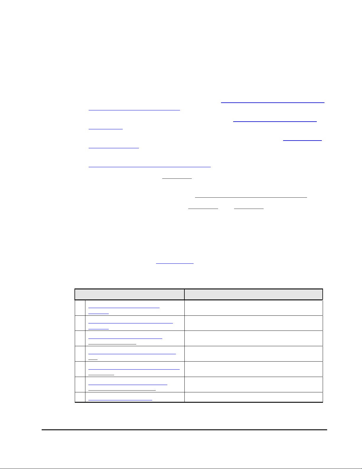
Document Organization
The following table provides an overview of the contents and organization of
this document. Click the chapter title
The first page of each chapter provides links to the sections within that
chapter.
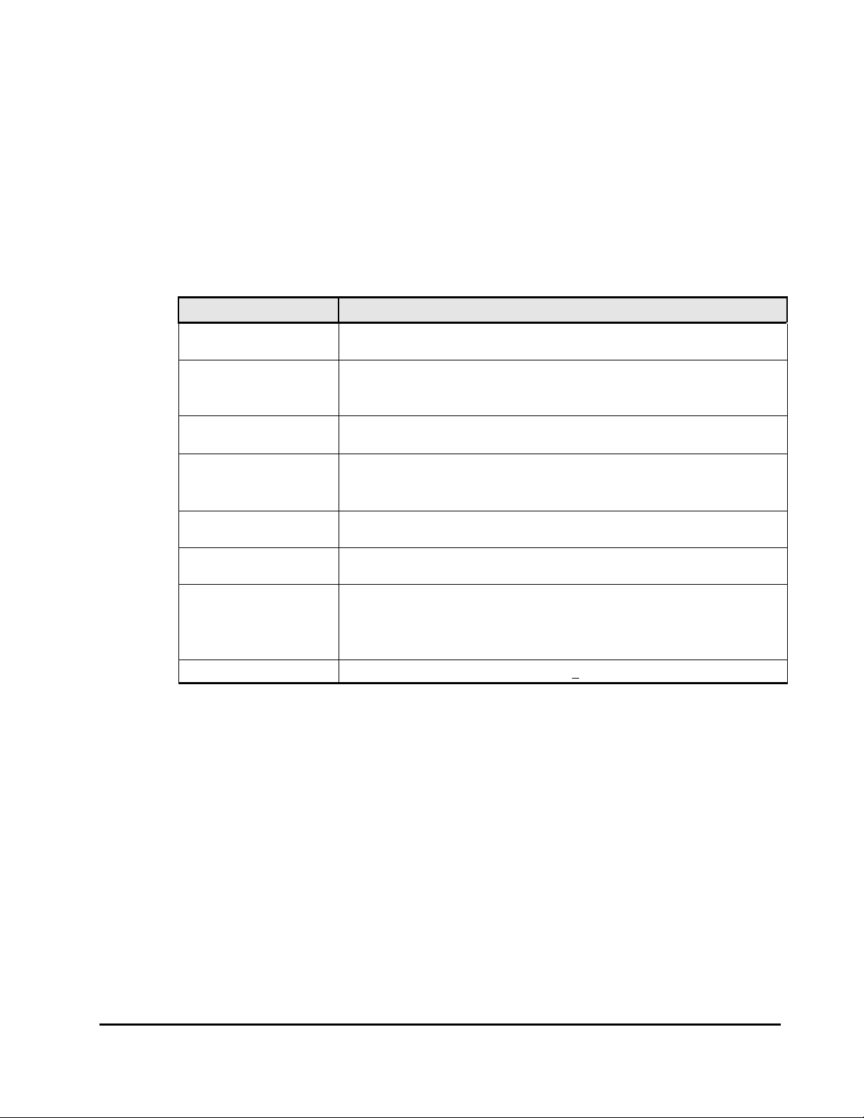
Chapter / Appendix Description
Overview of Universal Volume
1
Manager
About Universal Volume Operations
2
Manager
Preparing for Universal Volume
3
Manager Operations
Using the Universal Volume Manager
4
GUI
Performing Universal Volume Manager
5
Operations
Using Spreadsheets for Universal
6
Volume Manager Operations
7 Remote Command Devices Describes remote command devices.
in the left column to go to that chapter.
Provides an overview of Universal Volume Manager.
Explains the functions and applications of Universal
Volume Manager.
Describes the requirements and preparations for
Universal Volume Manager operations.
Explains the Universal Volume Manager windows.
Describes setting the external volume using Universal
Volume Manager.
Explains how to use spreadsheets for Universal Volume
Manager operations.
Preface xi
Hitachi Universal Storage Platform V/VM Universal Volume Manager User’s Guide
Page 12
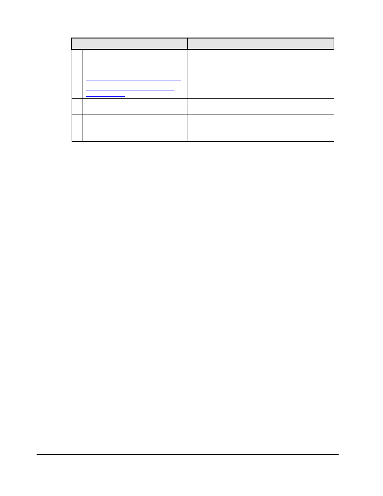
Chapter / Appendix Description
8 Troubleshooting
A Connecting External Storage Systems Describes configuration for external storage systems.
Required Volume Capacity for Each
B
Emulation Type
C Adjusting Volume Capacities for Pairs
- Acronyms and Abbreviations
- Index Lists the topics in this document in alphabetical order.
Referenced Documents
Hitachi Universal Storage Platform V/VM:
• Hitachi Command Control Interface (CCI) User and Reference Guide,
MK-90RD011
• Hitachi Copy-on-Write Snapshot User’s Guide, MK-96RD607
• Hitachi Dynamic Provisioning User's Guide, MK-96RD641
• Hitachi LUN Expansion User’s Guide, MK-96RD616
Provides troubleshooting information for Universal
Volume Manager and instructions for calling technical
support.
Describes the capacity list for each emulation type.
Describes how to adjust the volume capacity when
creating a pair.
Defines the acronyms and abbreviations used in this
document.
• Hitachi Performance Manager User’s Guide, MK-96RD617
• Hitachi ShadowImage User’s Guide, MK-96RD618
• Hitachi ShadowImage for IBM
®
z/OS® User’s Guide, MK-96RD619
• Hitachi Storage Navigator User’s Guide, MK-96RD621
• Hitachi Storage Navigator Messages, MK-96RD613
• Hitachi TrueCopy for IBM z/OS User’s Guide, MK-96RD623
• Hitachi TrueCopy User’s Guide, MK-96RD622
• Hitachi Universal Replicator for IBM z/OS User’s Guide, MK-96RD625
• Hitachi Universal Replicator User’s Guide, MK-96RD624
• Hitachi Virtual LVI/LUN and Volume Shredder User's Guide, MK-96RD630
• Hitachi Virtual Partition Manager User’s Guide, MK-96RD629
xii Preface
Hitachi Universal Storage Platform V/VM Universal Volume Manager User’s Guide
Page 13
Document Conventions
The terms “Universal Storage Platform V” and “USP V” refer to all models of
the Hitachi Universal Storage Platform V, unless otherwise noted.
The terms “Universal Storage Platform VM” and “USP VM” refer to all models of
the Hitachi Universal Storage Platform VM, unless otherwise noted.
This document uses the following typographic conventions:
Convention Description
Bold
Italic
screen/code
< > angled brackets
[ ] square brackets
{ } braces
| vertical bar
underline Indicates the default value. Example: [ a | b ]
Indicates text on a window, other than the window title, including menus,
menu options, buttons, fields, and labels. Example: Click OK.
Indicates a variable, which is a placeholder for actual text provided by the
user or system. Example: copy source-file target-file
Note: Angled brackets (< >) are also used to indicate variables.
Indicates text that is displayed on screen or entered by the user.
Example:
Indicates a variable, which is a placeholder for actual text provided by the
user or system. Example:
Note: Italic font is also used to indicate variables.
Indicates optional values. Example: [ a | b ] indicates that you can choose
a, b, or nothing.
Indicates required or expected values. Example: { a | b } indicates that
you must choose either a or b.
Indicates that you have a choice between two or more options or
arguments. Examples:
# pairdisplay -g oradb
# pairdisplay -g <group>
[ a | b ] indicates that you can choose a, b, or nothing.
{ a | b } indicates that you must choose either a or b.
Preface xiii
Hitachi Universal Storage Platform V/VM Universal Volume Manager User’s Guide
Page 14
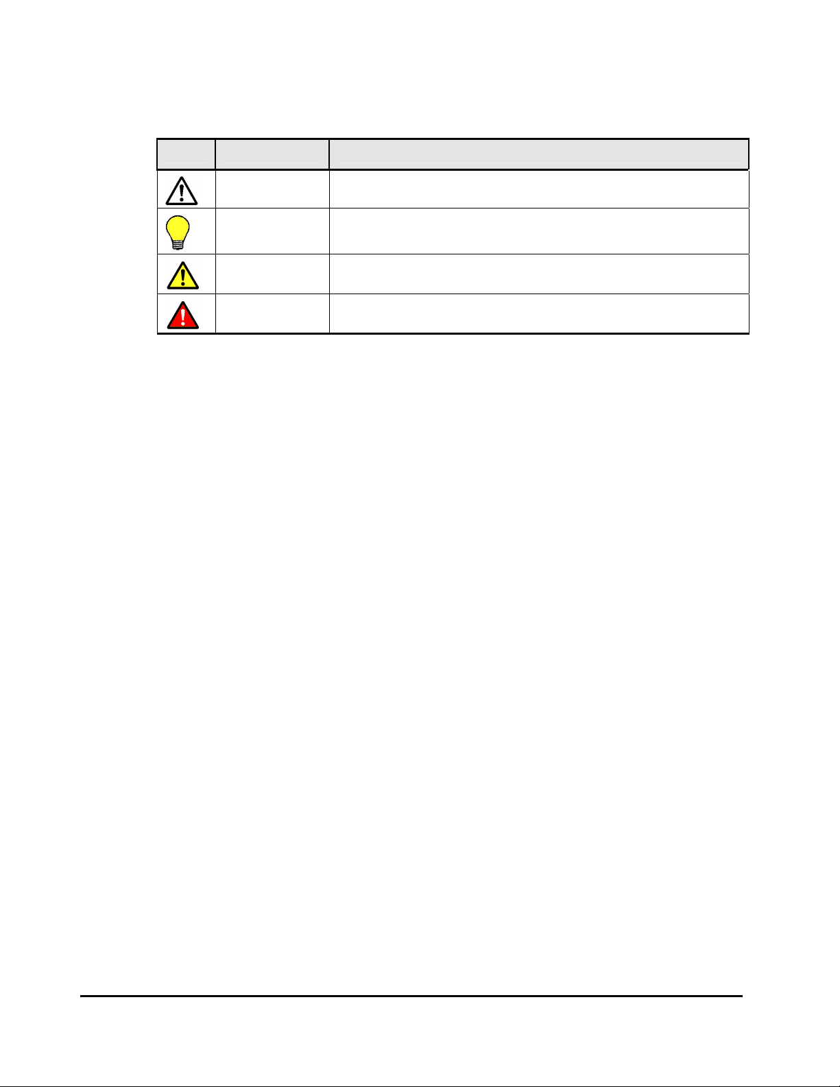
This document uses the following icons to draw attention to information:
Icon Meaning Description
Note Calls attention to important and/or additional information.
Tip
Caution
WARNING
Provides helpful information, guidelines, or suggestions for performing
tasks more effectively.
Warns the user of adverse conditions and/or consequences (e.g.,
disruptive operations).
Warns the user of severe conditions and/or consequences (e.g.,
destructive operations).
Convention for Storage Capacity Values
Physical storage capacity values (e.g., disk drive capacity) are calculated
based on the following values:
1 KB = 1,000 bytes
1 MB = 1,000
1 GB = 1,000
1 TB = 1,000
1 PB = 1,000
2
bytes
3
bytes
4
bytes
5
bytes
Logical storage capacity values (e.g., logical device capacity) are calculated
based on the following values:
1 KB = 1,024 bytes
1 MB = 1,024
1 GB = 1,024
1 TB = 1,024
1 PB = 1,024
2
bytes
3
bytes
4
bytes
5
bytes
1 block = 512 bytes
xiv Preface
Hitachi Universal Storage Platform V/VM Universal Volume Manager User’s Guide
Page 15

Getting Help
If you need to call the Hitachi Data Systems Support Center, be sure to
provide as much information about the problem as possible, including:
• The circumstances surrounding the error or failure.
• The content of any error messages displayed on the host system(s).
• The content of any error messages displayed by Storage Navigator.
• The USP V/VM Storage Navigator configuration information obtained by
using the FD Dump Tool
• The service information messages (SIMs), including reference codes and
severity levels, displayed by Storage Navigator and/or logged at the host.
The Hitachi Data Systems customer support staff is available 24 hours/day,
seven days a week. If you need technical support, please call:
• United States: (800) 446-0744
• Outside the United States: (858) 547-4526
Comments
Please send us your comments on this document. Make sure to include the
document title, number, and revision. Please refer to specific section(s) and
paragraph(s) whenever possible.
• E-mail: doc.comments@hds.com
• Fax: 858-695-1186
• Mail:
Technical Writing, M/S 35-10
Hitachi Data Systems
10277 Scripps Ranch Blvd.
San Diego, CA 92131
Thank you! (All comments become the property of Hitachi Data Systems
Corporation.)
Preface xv
Hitachi Universal Storage Platform V/VM Universal Volume Manager User’s Guide
Page 16

Page 17

1
Overview of Universal Volume Manager
This chapter provides an overview of Universal Volume Manager.
Universal Volume Manager
Unifying Copy Operations between Different Storage Systems
Unifying Connections from a Host to Different Storage Systems
Overview of Universal Volume Manager 1-1
Hitachi Universal Storage Platform V/VM Universal Volume Manager User’s Guide
Page 18

Universal Volume Manager
Universal Volume Manager software provides the virtualization of a multitiered storage area network comprised of heterogeneous storage systems. It
enables the operation of multiple storage systems connected to a USP V/VM as
if they were all in one storage system and provides common management
tools and software. The shared storage pool comprised of external storage
volumes can be used with storage system-based software for data migration
and replication, as well as any host-based application. Combined with Hitachi
Volume Migration software, Universal Volume Manager provides an automated
data lifecycle management solution, across multiple tiers of storage.
The key features and benefits of Universal Volume Manager include:
• Universal Volume Manager virtualizes external storage attached to the
USP V/VM storage system
• Enables deployment of multi-tiered storage
• Integrates heterogeneous systems
• Creates pools of storage independent of physical location
• Creates new opportunities based on enhanced capability of existing
business continuity software and management tools to external storage
devices
1-2 Overview of Universal Volume Manager
Hitachi Universal Storage Platform V/VM Universal Volume Manager User’s Guide
Page 19
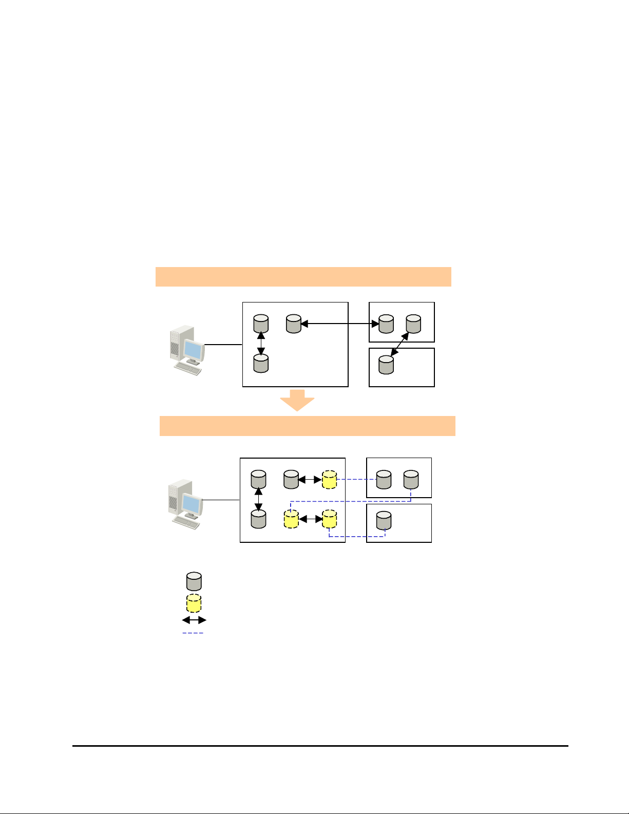
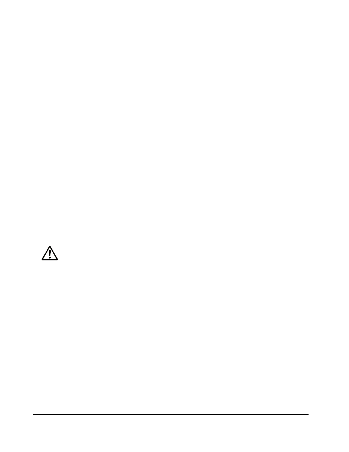
Unifying Copy Operations between Different Storage Systems
When you copy data between different storage systems, the copy operations
are usually different depending on the storage system which you use.
If you install Universal Volume Manager, you can perform the following copy
operations in the same way as when you copy data between volumes in the
USP V/VM storage system.
• To copy data between a volume in the USP V/VM storage system and a
volume in an external storage system.
• To copy data between a volume in an external storage system and a
volume in another external storage system.
Without UVM, different copy operations are required.
Storage
Navigator
Computer
External Storage System USP V/VM Storage System
UVM allows you to perform all copy operations in the same way.
Storage
Navigator
Computer
Legend
Volumes installed in the storage system
:
Virtual volumes that do not have physical memory space
:
Copy operation
:
Lines showing the concept of virtualization
:
External Storage System USP V/VM Storage System
Figure 1-1 Unifying Copy Operations between Different Storage
Systems
Overview of Universal Volume Manager 1-3
Hitachi Universal Storage Platform V/VM Universal Volume Manager User’s Guide
Page 20
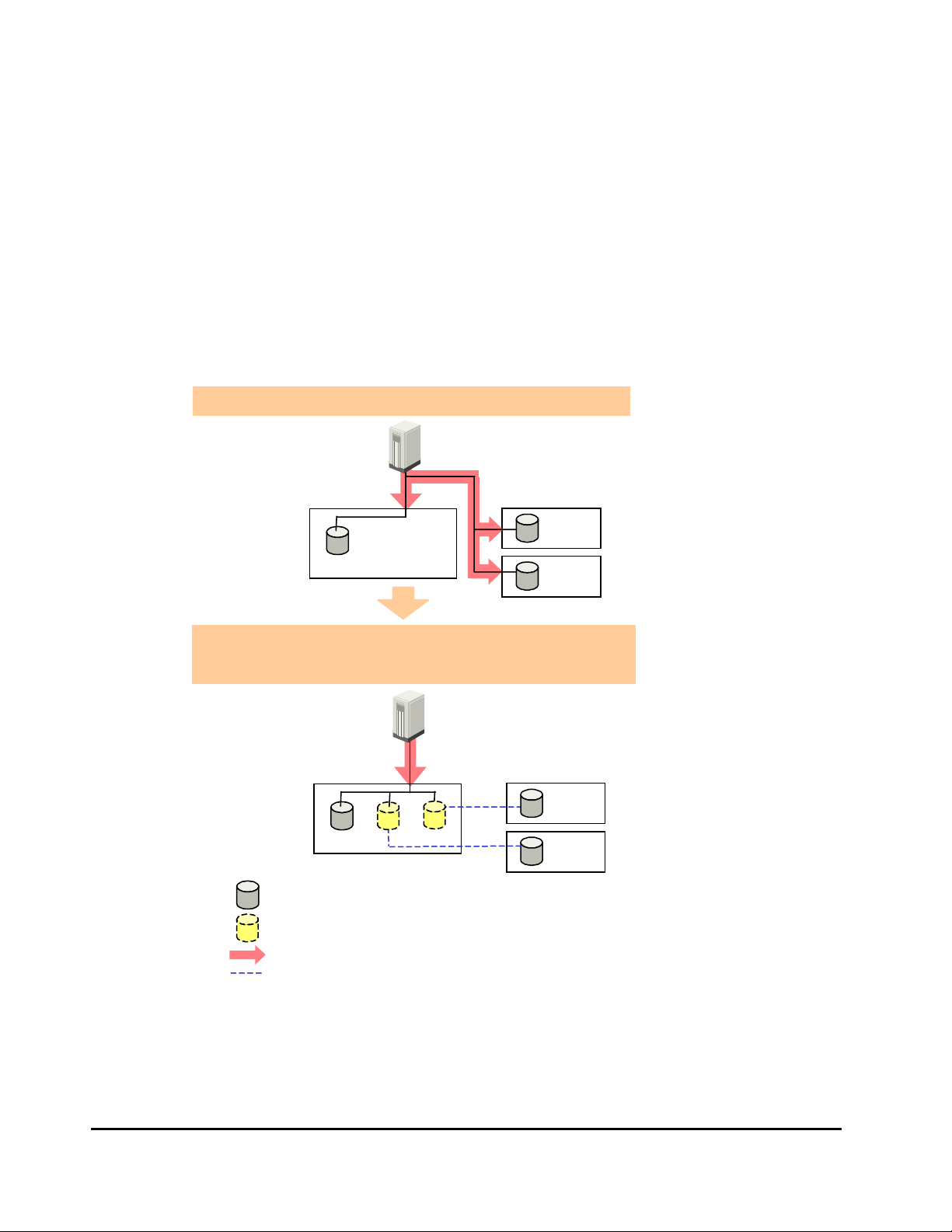
Unifying Connections from a Host to Different Storage Systems
When a system has multiple storage systems, a host usually needs to connect
all storage systems. When a system administrator configures the connections
from a host to volumes, they need to follow the different instructions
depending on the storage systems.
If you install Universal Volume Manager, a system administrator only needs to
configure the connection from a host to the USP V/VM storage system. After
the configuration is completed, a host can manipulate volumes in the external
storage system in the same way as volumes in the USP V/VM storage system.
Without UVM, a host needs to connect all storage systems.
Host
USP V/VM
Storage System
External Storage System
UVM allows you to unify the connections from a host
to different storage systems.
Host
Legend
USP V/VM
Storage System
Volumes installed in the storage system
:
Virtual volumes that do not have physical memory space
:
Access
:
Lines showing the concept of virtualization
:
External Storage System
Figure 1-2 Unifying Connections from a Host to Different Storage
Systems
1-4 Overview of Universal Volume Manager
Hitachi Universal Storage Platform V/VM Universal Volume Manager User’s Guide
Page 21

2
About Universal Volume Operations
Manager
This chapter explains the functions and applications of Universal Volume
Manager.
Connecting External Storage System
Universal Volume Manager Components
Universal Volume Manager Operations
Configuring Universal Volume Manager
Choosing Mapping Policy
Using a Mapped External Volume from a Connected Host
Interoperability with other Products and Functions
Examples of Using External Volumes with Other Products
About Universal Volume Manager Operations 2-1
Hitachi Universal Storage Platform V/VM Universal Volume Manager User’s Guide
Page 22
Connecting External Storage System
Universal Volume Manager enables you to use Hitachi storage systems,
original equipment manufacturer (OEM) storage systems, and other vendors'
storage systems (such as IBM or EMC) as connectable external storage
systems. Hosts will recognize these volumes as internal volumes of the
USP V/VM storage system. In this user's guide, the original USP V/VM storage
system is called "local storage system" and a connected storage system is
called the "external storage system".
External volume mapping is required for manipulating external volumes from
local storage system. “Mapping” means assigning the management numbers to
the external volumes. This management numbers are required for
manipulating external volumes from local storage system. By assigning the
management numbers to the external volumes, the system administrator will
be able to manipulate not only internal volumes of local storage system but
also external volumes using Storage Navigator. The management numbers
consist of "external volume group number - sequential number" (Example: E21, E50-3).
Figure 2-1 shows the idea of connection between a local storage system and
an external storage system which are connected by the Universal Volume
Manager function. In the
to the external port of the local storage system via a switch using the fibrechannel interface. The external port is a kind of port attribute, which is used
for Universal Volume Manager. In the
mapped as internal volumes.
Figure 2-1, the external storage system is connected
Figure 2-1, the external volumes are
Notes:
• Make sure that you do not access the external volume, which has been
mapped as an internal volume, from the host that is connected to the
external storage system. Also make sure that you do not access the
mapped external volume using the function (e.g., copy function) of the
external storage system. Once you have mapped an external volume as an
internal volume, you have to access the mapped external volume only from
the local storage system side.
• From the host, you can access the external storage system volumes that
have not been mapped as the internal volumes. There is no restriction.
2-2 About Universal Volume Manager Operations
Hitachi Universal Storage Platform V/VM Universal Volume Manager User’s Guide
Page 23
Host 1
Host 2
Fibre-Channel
Interface
Connection
Switch
Local Storage System
Internal
Vol umes
Legend
Volumes installed in the storage system
:
Virtual volumes that do not have physical memory space
:
Lines showing the concept of mapping
:
Figure 2-1 Concept of Universal Volume Manager
Target
Port
Target
Port
External
Port
External
Port
Mapping
External Storage System
Port
WWN 0
Port
WWN 1
By mapping an external volume as an internal volume using Universal Volume
Manager as shown in
Figure 2-1, it becomes possible to operate the external
volume using Storage Navigator as if it is a volume in the local storage
system.
About Universal Volume Manager Operations 2-3
Hitachi Universal Storage Platform V/VM Universal Volume Manager User’s Guide
Page 24
Universal Volume Manager Components
A
System using Universal Volume Manager usually contains the following
components:
– Local storage system (USP V/VM storage system)
– External storage system
– Storage Navigator computer
– Universal Volume Manager
– External volume
– Internal volume, which is a virtual representation of an external volume
– LDEVs (Logical Devices) in an external volume
– Cross-subsystem path
– Mapping path
The following figure illustrates the relations of the Universal Volume Manager
components.
Storage
Navigator
Computer
Legend
Host
Local Storage System
Target
Port
Set or View
SVP
(Web Server)
Volumes installed in the storage system
:
Virtual volumes that do not have physical memory space
:
Lines showing the concept of mapping
:
LDEVs in the
External Volume
Create
LDEVs
B
External
Port
External Storage System
C
Mapping
Port
WWN
Cross-subsystem Path
Mapping Path
External
Vol ume
Figure 2-2 Universal Volume Manager Components
This section describes the details of the storage systems, cross-subsystem
paths, volumes and mapping paths as shown in the above figure.
2-4 About Universal Volume Manager Operations
Hitachi Universal Storage Platform V/VM Universal Volume Manager User’s Guide
Page 25
Storage Systems and Cross-subsystem Paths
Before using Universal Volume Manager, connect the fibre channel port of the
local storage system to the external storage system port with the fibre cable.
The route between ports, which is connected with the cable, is called the
"cross-subsystem path".
The fibre channel port of the local storage system is set to connect to the host
by default. The fibre channel port can be connected to an external storage
system if you change the attribute of the fibre channel port so that it is an
external port, which can be connected to an external storage system. The
external storage system port can be a target port, which can be connected to
a host.
To manipulate Universal Volume Manager, you need to install Universal
Volume Manager by using the license key. Use your Storage Navigator
computer to access the local storage system via SVP (web server) and perform
the Universal Volume Manager operations.
Volumes and Mapping Paths
Volumes in the external storage system (see C in Figure 2-2) are called
"external volumes". Mapping is necessary to manipulate an external volume
from the local storage system. The system administrator maps an external
volume as an internal volume (see B in
After the mapping, you can manipulate the external volume from the local
storage system in the same way as manipulating an internal volume.
Figure 2-2) in the local storage system.
Note: When external volumes in external storage systems are mapped as
internal volumes in your USP V/VM storage systems, the external volumes can
be accessed and copied by hosts connecting to your USP V/VM storage
systems, but not by hosts connecting to the external storage systems.
This document sometimes uses the term "an external volume" or "a mapped
external volume" to mention an internal volume where an external volume is
mapped (see B in
representation of an external volume.
When you perform mapping, a path is automatically created between an
internal volume and an external volume. This path is called "a mapping path",
which connects one volume with another volume. A cross-subsystem path is a
part of a mapping path.
About Universal Volume Manager Operations 2-5
Figure 2-2), because this internal volume is a virtual
Hitachi Universal Storage Platform V/VM Universal Volume Manager User’s Guide
Page 26

To use the external volumes, which you mapped as an internal volume (see B
in
Figure 2-2), from the host or other program products, the system
administrator needs to create LDEVs in the external volume (see A in
Figure
2-2). To create LDEVs, use Universal Volume Manager at the time of mapping,
or use VLL function to an internal volume where an external volume is mapped
after mapping. The LDEVs created by these methods are called “LDEVs in the
external volume” in this document. These LDEVs are usually called “external
volumes” in other documents.
An external volume corresponds to a VLL VDEV (Virtual Device). An LDEV in
the external volume corresponds to a VLL LDEV. Therefore, you can use VLL
function to create custom-sized volumes in an external volume after mapping,
in the same way as creating custom-sized volumes in the normal internal
volumes. For details on VDEVs and LDEVs, see the Virtual LVI/LUN and Volume
Shredder User's Guide.
2-6 About Universal Volume Manager Operations
Hitachi Universal Storage Platform V/VM Universal Volume Manager User’s Guide
Page 27

Universal Volume Manager Operations
Universal Volume Manager enables you to execute the following operations.
• Preparing to use external volumes
You can map external volumes, set port attributes, and set crosssubsystem paths.
• Preparing to manipulate the power supply of the storage systems
You must follow specific procedures if you want to manipulate the power
supply of the storage systems when external volumes are used. To turn on
or off the power supply of the external storage system after starting to use
the external volumes, you need to execute the commands of Universal
Volume Manager.
• Setting up and removing the cross-subsystem paths
When you set up or remove the path (cable) connecting the storage
systems, you need to use the Universal Volume Manager to make settings
on the path.
• Referring to the status of external volumes
You can refer to the status and the configuration of external volumes.
• Stopping the use of external volumes
You can cancel mapping of external volumes.
• Mapping external volumes by using spreadsheets
Universal Volume Manager supports the Configuration File Loader
spreadsheets. Spreadsheets allow you to configure the mapping of multiple
external volumes at one time, which is efficient when mapping a large
number of volumes.
• Setting the remote command device
By using the remote command device, you can manipulate volumes in the
external storage system from the Command Control Interface on host
computers.
About Universal Volume Manager Operations 2-7
Hitachi Universal Storage Platform V/VM Universal Volume Manager User’s Guide
Page 28
Configuring Universal Volume Manager
g
Before configuring the Universal Volume Manager settings, you need to answer
the following:
• Which ports can be connected to external storage systems
• Which external storage system and volumes should be mapped as the
internal volumes
• How to configure external volume groups
• What external volume attributes to be configured
• How to configure cross-subsystem paths
• How to make volume usable from the local storage system
Choosing External Port
The port used for Universal Volume Manager must be set as the external port.
When the external storage system is connected to the external port of the
local storage system, you can view the information on the external storage
system from the Storage Navigator computer. The external storage system
cannot be connected to the ports other than the external port.
In order to set the port attribute to external, the LU paths set to the port must
be released. The attribute of the port where the LU paths are already set
cannot be changed to external. Therefore, you must identify ports whose
attributes can be changed to external before starting the Universal Volume
Manager operations.
Note: The ports whose attributes are set for remote copy software (e.g., RCU
target, initiator) or other features cannot be used as external ports for
Universal Volume Mana
the port attribute is set to other than external.
er. In addition, change the port attribute to external if
Choosing and Mapping External Volumes
When you connect an external storage system to an external port, volumes in
the external storage system (external volumes) become available for mapping
as volumes in the local storage system (internal volumes). Identify the
volumes in each external storage system that should be mapped as internal
volumes.
• You cannot access the data that is stored in an external volume beyond the
maximum available capacity.
2-8 About Universal Volume Manager Operations
Hitachi Universal Storage Platform V/VM Universal Volume Manager User’s Guide
Page 29

For example, if an external volume of 100 GB was mapped as an internal
volume of 70 GB, then 30 GB of the external volume would not be
accessible from the local storage system side.
• You cannot map an external volume whose capacity is smaller than the
minimum available capacity.
For example, you cannot map an external volume of 10 GB as an internal
volume which requires at least 30 GB.
The maximum or minimum available capacity of an external volume depends
on the emulation type that is set when the volume is mapped.
Registering a Volume to an External Volume Group (ExG)
When you map an external volume as an internal volume, you need to register
the external volume to an external volume group.
External volumes, which are set by Universal Volume Manager, can be
classified into groups by usage. Any group of this type is called an external
volume group (ExG). For instance, you can register multiple volumes in one
external storage system to one external volume group. Or you can register the
volumes in one external volume group and manage them in block, even
though the data you want to manage in a lump is stored in volumes in the
different external storage systems.
You need to assign numbers to external volume groups.
Configuring External Volume Attributes
When you map an external volume as an internal volume, you set the
attributes of the external volume. External volume attributes can be set using
the mapping policy or the Set External Volume Parameter dialog box of the
Universal Volume Manager.
The attributes of the external volume are as follows:
• Emulation type
Select an emulation type for the mapped external volume from the dropdown list.
The emulation type OPEN-V must be selected if, after the mapping, you
are planning to use the existing data in the external volume from the local
storage system. For example, if you want to migrate the existing data in
the external volume to the local storage system volume, you have to set
the OPEN-V emulation type when the external volume is mapped.
If you select the emulation type other than OPEN-V, the volume requires a
specific area provided for management data. Once this area is provided,
volume capacity after the mapping becomes less than the actual external
volume capacity for the area (volume).
About Universal Volume Manager Operations 2-9
Hitachi Universal Storage Platform V/VM Universal Volume Manager User’s Guide
Page 30
• Cache Mode (Enable or Disable)
Cache mode specifies whether the write data from the host to the external
storage system is propagated synchronously (Disable) or asynchronously
(Enable). By default, cache mode is set to Enable. All I/O to and from the
local storage system (either Enable or Disable) always uses cache. Write
operations are always backed up in duplex cache.
– If you select Enable, after receiving the data into the local storage
system cache memory, the local storage system signals the host that
an I/O operation has completed and then asynchronously destages the
data to the external storage system.
– If you select Disable, the local storage system signals the host that an
I/O operation has completed only after the local storage system has
synchronously written the data to the external storage system.
If you perform the Cache Residency Manager operation on the external
volume, which the Cache Mode is set to Disable, the bind mode of
Cache Residency Manager cannot be specified. For the Cache Residency
Manager operation, see the Cache Residency Manager User’s Guide.
Note: When you set the cache mode, note the following:
• Data that is not written by the host (for example, data written by
ShadowImage) is asynchronously destaged to the external storage
system regardless of the Cache Mode setting.
• If you set the emulation type for a mainframe system (such as 3390x), data that is written by a host using a command such as Format
Write is asynchronously destaged to the external storage system
regardless of the Cache Mode setting. Data that is written by a host
using a command such as Update Write is destaged to the external
storage system as configured in the Cache Mode setting.
• Inflow Control (Enable or Disable)
Inflow control specifies whether the writing operation to the cache memory
is stopped (Enable) or continued (Disable) when the writing operation to
the external volume is impossible. By default, inflow control is set to
Disable.
– If you select Enable, the writing operation to cache is stopped and the
I/O from the host is not accepted when the writing operation to the
external volume is impossible.
– If you select Disable, the I/O from the host during the retry operation
is written to the cache memory even after the writing operation to the
external volume is impossible. Once the writing operation to the
external volume becomes normal, all the data in the cache memory is
written to the external volume (all the data is destaged).
2-10 About Universal Volume Manager Operations
Hitachi Universal Storage Platform V/VM Universal Volume Manager User’s Guide
Page 31

• CLPR
When the cache memory is partitioned using Virtual Partition Manager,
configure a cache logical partition (CLPR) to access the mapped volume.
See the Virtual Partition Manager User’s Guide for the detailed information
on CLPR.
Cross-subsystem Paths
A cross-subsystem path is a route from a local storage system port to an
external storage system port. To prepare for possible failures of the cable, the
switch, or the channel processor, it is recommended that you create redundant
cross-subsystem paths. This redundancy allows you to continue performing
the I/O operations to the external volumes when you maintain the cable. You
can set up to eight paths.
A group of redundant cross-subsystem paths is called a "path group". In a
path group, the cross-subsystem path that has the highest priority is called
the primary path. The cross-subsystem paths other than priority path are
called alternate paths.
• Setting of the path groups
Path Mode
A path group is automatically set when you map the external volume. You
cannot set a new path group by itself.
• Setting of cross-subsystem paths
Use fibre cables to establish multiple paths between the external storage
system and the local storage system. At this time, connect to the external
storage system from the different cluster port of the local storage system.
If multiple paths are established between the two storage systems, the
starting points of the paths (i.e., external ports of the local storage system)
and the ending points (i.e., WWNs showing the ports of the external
storage system) will be displayed in a dialog box when you map an
external volume. In this dialog box, you can set cross-subsystem paths by
selecting the starting points and the ending points of the paths according
to the actual cable connections.
• Setting of redundant cross-subsystem paths
You can set redundant cross-subsystem paths (add alternate paths) when
you set the cross-subsystem paths. You can also add an alternate path or
change the priority after completing the mapping of the external volume.
Path mode is either Single mode or Multi mode, depending on the connected
external storage system.
About Universal Volume Manager Operations 2-11
Hitachi Universal Storage Platform V/VM Universal Volume Manager User’s Guide
Page 32

• In the Single mode, only the path with the highest priority (primary path)
is used to execute the I/O to the external volume. When an error occurs in
the primary path, the path with the second highest priority is used.
• In the Multi mode, all of the set paths are used at the same time. The
multiple paths are used to execute the I/Os to the external volume thus
distributing the work load (round-robin processing).
For example, when a volume in the external storage system with the path
mode of the Single mode is mapped as an internal volume using Universal
Volume Manager, the host I/O operations to the external volume are enabled
using the primary path set in the mapping operation. The path is automatically
switched to the alternate path when the primary path set in mapping operation
cannot be used due to, for instance, maintenance operation in the storage
system, or a failure in the channel processor. Because the path is switched to
the alternate path, the I/O operation to the external volume continues even
though an error occurred in the original path.
Note: When the primary path cannot be used for three minutes continuously,
the path is switched to the alternate path.
Examples of Alternate Paths
Figure 2-3 illustrates an example of setting an alternate path. External storage
system ports, “WWN A” and “WWN B”, are connected to “CL1-A” and “CL2-A”
respectively, which are set to the external ports in the local storage system.
You need to specify the port of a different cluster in the local storage system
for the alternate path. Therefore, “CL1” port and “CL2” port are specified.
2-12 About Universal Volume Manager Operations
Hitachi Universal Storage Platform V/VM Universal Volume Manager User’s Guide
Page 33

Local Storage System
External Storage System
Internal
Vol ume
Legend
:
External
CL1-A
External
CL2-A
Internal volume where external volume is mapped
A
B
Path 1
WWN A
Path 2
WWN B
Port
Port
LUN
5
External
Volume
LUN
5
Figure 2-3 Example of Alternate Path Setting
Figure 2-4 illustrates an example of setting an alternate path when a switch is
used. Two ports are specified in the local storage system, and connected to
the ports in the external storage system through the switch. In this case, two
ports of different clusters are specified in the local storage system. Therefore,
the setting of the alternate path is enabled.
Local Storage System
External Storage System
Switch
Internal
Vol um e
Legend
:
External
A
Path 1
CL1-A
External
B
Path 2
CL2-A
Internal volume where the external volume is mapped
Port
WWN A
Port
LUN
5
LUN
5
Figure 2-4 Example of Available Alternate Path Setting
External
Vol um e
About Universal Volume Manager Operations 2-13
Hitachi Universal Storage Platform V/VM Universal Volume Manager User’s Guide
Page 34

In Figure 2-5, two paths are also set between the internal volume and the
external volume. However, one port is specified in the local storage system,
and two ports are specified in the external storage systems over the switch.
This configuration is not recommended because two ports of different clusters
need to be set in the local storage system for alternate path settings in
Universal Volume Manager.
Local Storage System
Internal
Vol um e
Legend
:
External
CL1-A
Internal volume where the external volume is mapped
Switch
Path 1
Path 2
External Storage System
Port
WWN A
Port
WWN B
LUN
5
LUN
5
Figure 2-5 Example of Unavailable Alternate Path Setting
Examples of Switching I/O Execution Paths to Alternate Paths
External
Vol um e
This section describes the case examples of the performance when the I/O
execution path is switched to the alternate path for each path mode as
follows:
– When the path mode is Multi mode
– When the path mode is Single mode
– When the path mode is Single mode and there is at least one alternate
path in the Standby status
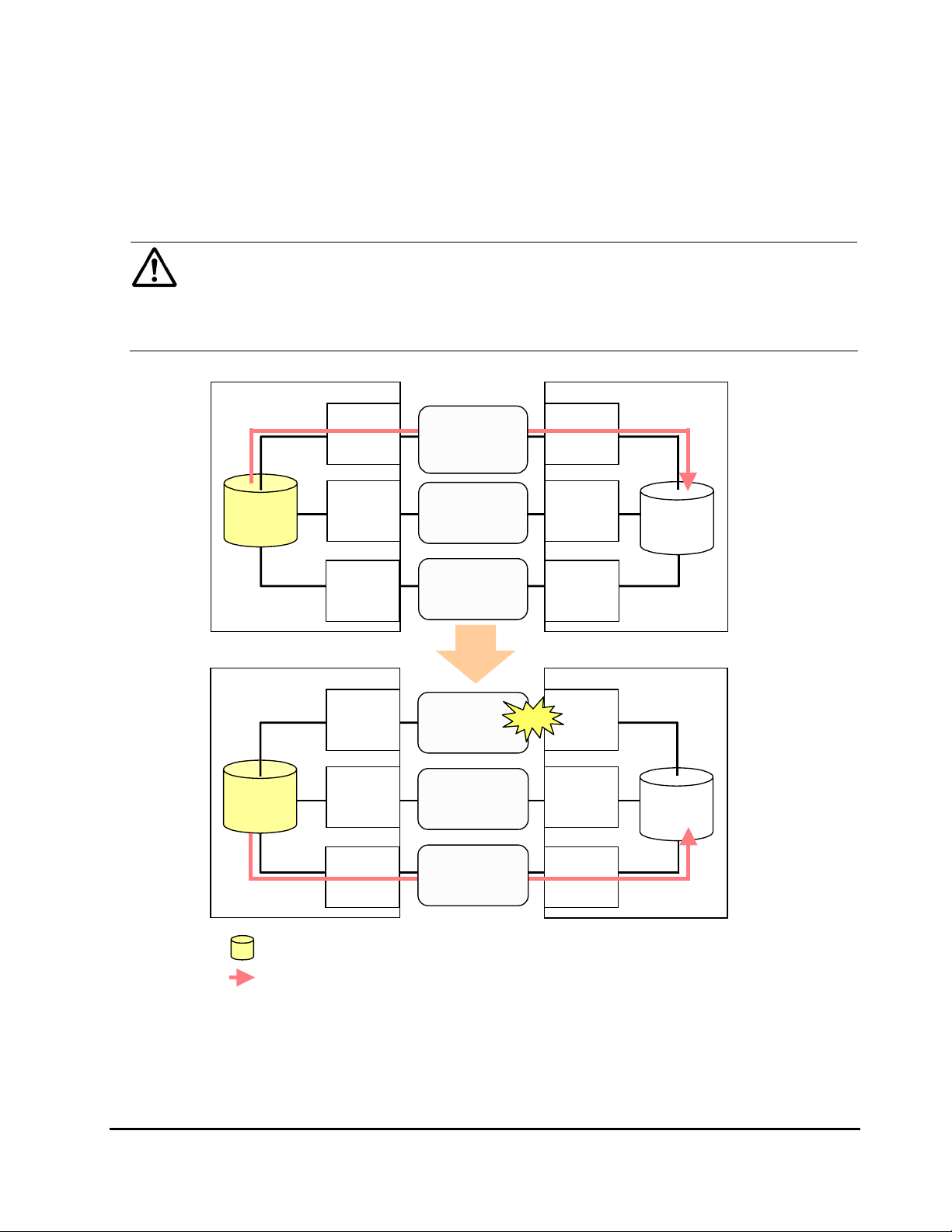
• When the path mode is Multi mode
Figure 2-6 shows an example of the case when the path mode is Multi
mode. When an error occurs in one path, I/Os are executed using the
paths other than the error path.
Note: As you restore the error path, the use of the restored path is
automatically resumed.
2-14 About Universal Volume Manager Operations
Hitachi Universal Storage Platform V/VM Universal Volume Manager User’s Guide
Page 35

Local Storage System
External Storage System
Internal
Vol ume
Internal
Vol ume
External
Port A
External
Port B
External
Port C
External
Port A
External
Port B
Path
Priority 1
Path
Priority 2
Path
Priority 3
Path
Priority 1
Path
Priority 2
Error
Port
WWN A
Port
WWN B
Port
WWN C
External Storage System Local Storage System
Port
WWN A
Port
WWN B
External
Volume
External
Vol ume
External
Port C
Legend
: Internal volume where the external volume is mapped
: I/O
Path
Priority 3
Figure 2-6 When the Path Mode is Multi Mode
• When the path mode is Single mode
Figure 2-7 shows an example of the case when the path mode is Single
mode. When an error occurs in the path that is being used for I/Os, the I/O
execution path is switched to the path with the second highest priority.
Note: As you restore the path with the priority higher than the currently
used path, the I/O execution path is automatically switched to the restored
path that has the highest priority.
Port
WWN C
About Universal Volume Manager Operations 2-15
Hitachi Universal Storage Platform V/VM Universal Volume Manager User’s Guide
Page 36

Local Storage System
External Storage System
Internal
Vol ume
Internal
Vol ume
External
Port A
External
Port B
External
Port C
External
Port A
External
Port B
Path
Priority 1
Path
Priority 2
Path
Priority 3
Path
Priority 1
Path
Priority 2
Error
Port
WWN A
Port
WWN B
Port
WWN C
External Storage System Local Storage System
Port
WWN A
Port
WWN B
External
Volume
External
外部
Vol ume
ボリューム
External
Port C
Legend
: Internal volume where the external volume is mapped
: I/O
Path
Priority 3
Port
WWN C
Figure 2-7 When the Path Mode is Single Mode
• When the path mode is Single mode and there is at least one alternate
path in the Standby status
Figure 2-8 shows an example of the case when the path mode is Single
mode, and there are the alternate paths in the Normal status and the
Standby status.
path mode is Single mode. In the case of
paths in the Standby status only.
Figure 2-9 shows another example of the case when the
Figure 2-9, there are alternate
2-16 About Universal Volume Manager Operations
Hitachi Universal Storage Platform V/VM Universal Volume Manager User’s Guide
Page 37
When an error occurs in the path that is being used for I/Os, the I/O
execution path is switched to the path with the second highest priority in
the Normal status. If there is no path in the Normal status other than the
path that is being used for I/Os, the status of the path in the Standby
status is automatically changed to Normal, and the I/O execution path is
switched to that path.
Note: Only when the external storage system is EVA storage system, as
you restore the path with the highest priority, the I/O execution path is
switched back to the restored highest priority path. In this case, the status
of the path for which the status has been changed to Normal when the
error has occurred is changed back to Standby.
Local Storage System
Internal
Volume
Internal
Volume
External
Port A
External
Port B
External
Port C
External
Port A
External
Port B
Path
Priority 1
Status:
Normal
Path
Priority 2
Status: Standby
Path
Priority 3
Status: Normal
Path
Priority 1
Status :
Blockade
Path
Priority 2
Status: Standby
External Storage System
Port
WWN A
Port
WWN B
Port
WWN C
External Storage System Local Storage System
Error
Port
WWN A
Port
WWN B
External
Volume
External
Volume
External
Port C
Legend
: Internal volume where the external volume is mapped
: I/O
Path
Priority 3
Status: Normal
Port
WWN C
Figure 2-8 Single Mode with Alternate Paths in Normal and Standby
About Universal Volume Manager Operations 2-17
Hitachi Universal Storage Platform V/VM Universal Volume Manager User’s Guide
Page 38

Local Storage System
External
Port A
Priority 1
Status:
Path
Normal
External Storage System
Port
WWN A
Internal
Volume
Internal
Volume
External
Port B
External
Port C
External
Port A
External
Port B
External
Port C
Path
Priority 2
Status:
Stan db y
Path
Priority 3
Status:Standby
Path
Priority 1
Status:
Blockade
Path
Priority 2
Status:
Normal
Path
Priority 3
Status: Standby
Error
Port
WWN B
Port
WWN C
External Storage System Local Storage System
Port
WWN A
Port
WWN B
Port
WWN C
External
Volume
External
Volume
Legend
: Internal volume where the external volume is mapped
: I/O
Figure 2-9 Single Mode with Alternate Paths in Standby only
2-18 About Universal Volume Manager Operations
Hitachi Universal Storage Platform V/VM Universal Volume Manager User’s Guide
Page 39

Connecting Mainframe Volumes
Mainframe volumes, that pre-exist on an external storage system and are
accessed by ESCON or FICON channels, cannot connect directly to the
USP V/VM storage system as an external volume. The USP V/VM storage
system does not recognize these volumes because of the fibre channel.
To use external volumes as mainframe volumes, there are two ways:
• Zero-format external volumes on the external storage system side, map
the external volumes to the internal volumes using Universal Volume
Manager on the local storage system side, and then perform the Write to
Control Blocks operation using the VLL function on the local storage
system side.
• Map the external volumes to the internal volumes using Universal Volume
Manager on the local storage system side, and then format the mapped
external volumes using the VLL function on the local storage system side.
If you set the emulation type for the mainframe system (e.g., 3390) as you
map the external volume, the status of the mapped volume becomes Blockade
after the mapping operation. After the system administrator performs the
Write to Control Blocks operation or formats the mapped external volumes
using VLL function on the local storage system side, the mainframe host can
then access the new mainframe volume through the local storage system’s
ESCON or FICON channels.
Note: If you format the mapped volume of the external storage system from
the external storage system side, the existing data before formatting cannot
be assured. When you use the mapped external volume from the mainframe
OS, format the mapped volume from the local storage system (USP V/VM)
side.
For the procedure of the volume formatting operation and the Write to
Control Blocks operation, see the Virtual LVI/LUN and Volume Shredder
User's Guide.
Connecting Open Systems Volumes
Open systems volumes in external storage systems connect to and are
recognized by the USP V/VM storage system as open systems volumes,
without requiring reformatting. Reformatting is not required because the
connection between the USP V/VM storage system and the external storage
system is fibre channel. If you need to initialize the data area for the volume,
format the volume using the VLL function. For the procedure of the volume
formatting operation, see the Virtual LVI/LUN and Volume Shredder User's
Guide.
About Universal Volume Manager Operations 2-19
Hitachi Universal Storage Platform V/VM Universal Volume Manager User’s Guide
Page 40

OPEN-V emulation is recommended because, in most cases, OPEN-V
emulation provides the most efficient use of storage and the best performance.
Also, emulation types other than OPEN-V may not retain existing data after
being mapped.
Choosing Mapping Policy
Policy is a list of settings of the necessary information for mapping the
external volume. By setting the mapping policy in advance, the setting at the
time of mapping will be easier.
One policy is prepared in advance. The user can change the default value of
the policy.
Difference between Automatic Mapping and Manual Mapping
When you map the external volume, you need to configure:
• cross-subsystem paths
• external volume parameters
• LDEV number to LDEVs in the external volume
• SSID (storage subsystem ID)
When you perform automatic mapping, users configure only cross-subsystem
paths and all the other settings above are automatically made by Universal
Volume Manager according to the mapping policy. When you perform manual
mapping, users configure all the settings.
Automatic mapping maps all the external volume found by the Volume
Discovery to the internal volumes. Automatic mapping requires less settings
but you are not allowed to set different parameters to each external volume or
to specify LDEV number to each LDEV. You can set the parameters such as
emulation type to mapping policy in advance.
Port Discovery and Volume Discovery
Port Discovery and Volume Discovery are the processes to find external
volumes, and will be executed when you map external volumes or when you
add cross-subsystem paths.
Port Discovery is a process to search for and get information about target
ports of the connected external storage system from an external port of the
local storage system. The latest information about the external storage system
can be viewed in a dialog box of the Universal Volume Manager when you
execute Port Discovery.
2-20 About Universal Volume Manager Operations
Hitachi Universal Storage Platform V/VM Universal Volume Manager User’s Guide
Page 41

You can set in advance the mapping policy on whether to execute the Port
Discovery automatically or manually. If Port Discovery is executed
automatically, WWNs connected to all the external ports of the local storage
system will be searched for. If Port Discovery is executed manually, you can
select a specific external port and limit the scope to search WWNs. If you can
specify which external port to search for, you can reduce the operation time by
executing the Port Discovery manually.
Volume Discovery is a process to search for and get information about external
volumes from the target ports of the external storage system. Volume
Discovery is automatically executed after the Port Discovery process.
Note: When a port in an external storage system is connected to USP V/VM
and has a management LU (for example, Universal Xport LU), an extra
operation is required. A management LU is an LU that receives commands
issued by a particular application. The management LU controls or manages
that application. The management LU stores control information from that
application and therefore the management LU cannot be used as an external
volume. A command device is not a management LU.
Before performing port discovery or volume discovery, perform one of the
following operations on the external storage system.
• Delete the management LU from the port connected to USP V/VM.
• Make sure that at least one LU is used for data storage and has a smaller
LUN than the LUN of the management LU. Also make sure that the data
storage LU is set to the port connected to USP V/VM.
• Use the security function and configure the access attribute of the
management LU to prohibit read and write operations.
If none of the above operations are performed, an external storage system
that has a management LU might not be recognized by the local storage
system.
About Universal Volume Manager Operations 2-21
Hitachi Universal Storage Platform V/VM Universal Volume Manager User’s Guide
Page 42

Using a Mapped External Volume from a Connected Host
There are two ways of using the mapped external volume from a host that is
connected the local storage system.
• Storing the new data in the mapped external volume
• Using the existing data in the mapped external volume
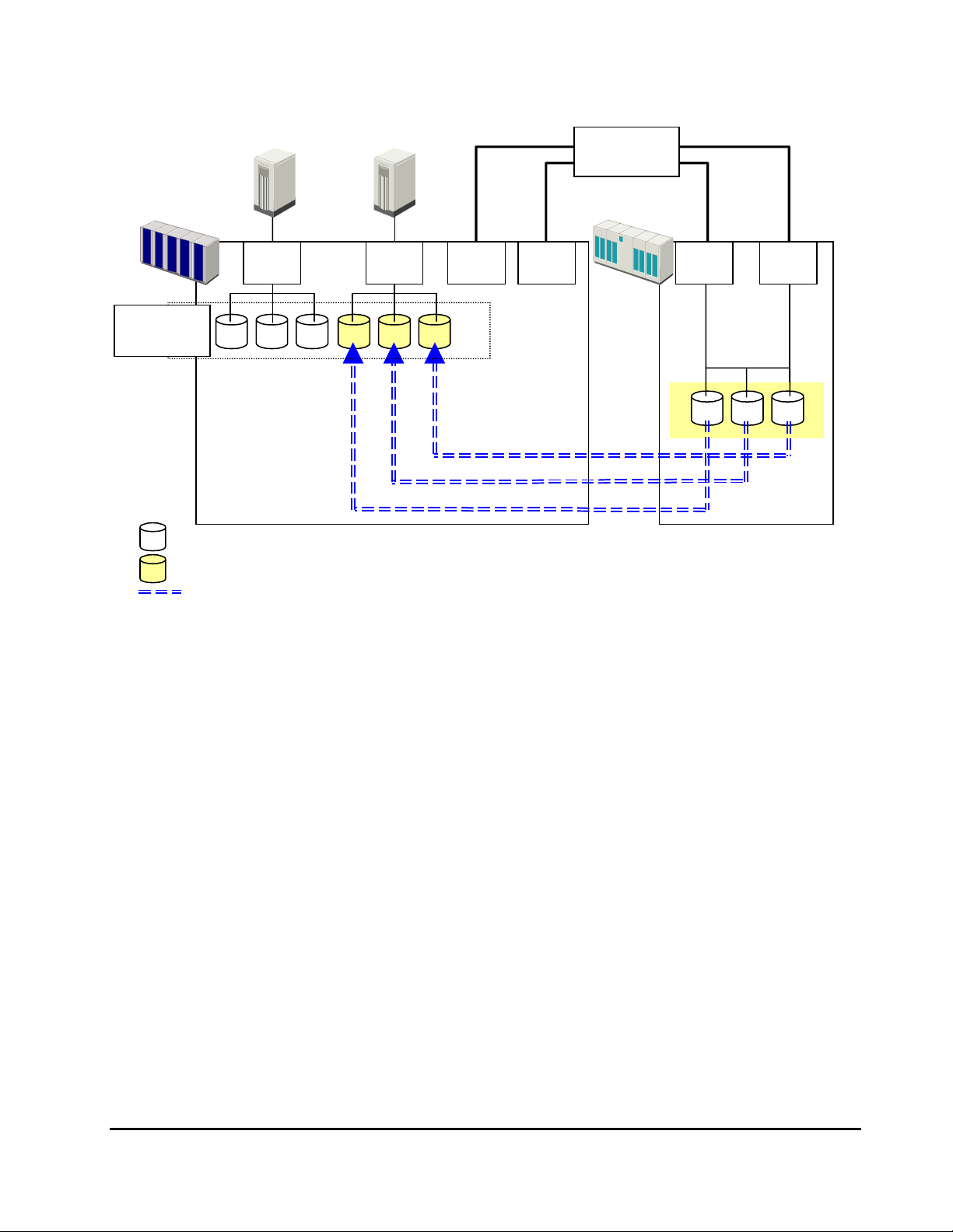
Storing New Data in the Mapped External Volume
To store new data in a mapped external volume from a host that is connected
to the local storage system:
1. Map the volume in the external storage system as an internal volume of
the local storage system using Universal Volume Manager.
Select the emulation type of the mapped volume as you required. If you
select the emulation type for the open system (such as OPEN-V), go on to
the step 2. If you select the emulation type for the mainframe system
(such as 3390-3), go on to the step 3.
2. If you set the emulation type for the open system when you map the
volume, the status of the mapped volume automatically becomes Normal.
If you need to initialize the data area of the mapped volume, format the
volume using the VLL function. For the volume formatting procedure, see
the Virtual LVI/LUN and Volume Shredder User's Guide.
Go on to the step 4.
3. If you set the emulation type for the mainframe system when you map the
volume, the status of the mapped volume becomes Blockade. Format the
volume using the VLL function.
Note: For zero-formatted
map, you can use the VLL function to perform the Write to Control Blocks
operation to restore the volume. For instructions on how to format volumes
and the Write to Control Blocks operation, see the Virtual LVI/LUN and
Volume Shredder User's Guide.
Go on to the step 4.
4. To perform the host I/O operations, set the LU path from the Target port to
the mapped volume.
After the LU path is set, the host I/O operation to the mapped volume
becomes available.
external volumes, when you select that volume to
2-22 About Universal Volume Manager Operations
Hitachi Universal Storage Platform V/VM Universal Volume Manager User’s Guide
Page 43

Host
Set the Target port and set the LU path
from the Target port for the host I/O.
Local
Storage System
Legend
: Internal volume where the external volume is mapped
: External volume
Target
Port
Mapping
External
Storage System
Figure 2-10 Storing the New Data in the Mapped External Volume
Using Existing Data in the Mapped External Volume
To use the existing data in the mapped external volume from the host that is
connected to the local storage system:
1. Store the data from the host that is connected to the external storage
system to the volume in the external storage system .
2. Map the volume containing data in the external storage system as an
internal volume of the local storage system using Universal Volume
Manager.
When you map the external volume, set the attributes of the mapped
volume as follows:
– Emulation type: OPEN-V
Note: You have to set the emulation type to OPEN-V to read the existing
data in the mapped external volume from the local storage system side.
3. Set the LU path from the Target port to the mapped volume to perform
the host I/O operation.
After the LU path is set, the host I/O operation to the mapped volume can
be initiated.
About Universal Volume Manager Operations 2-23
Hitachi Universal Storage Platform V/VM Universal Volume Manager User’s Guide
Page 44

Notes:
• Make sure that you do not access the external volume, which has
been mapped as a internal volume, from the host that is connected to
the external storage system. Also make sure that you do not access
the mapped external volume using the function (e.g., copy function)
of the external storage system. Once you have mapped an external
volume as an internal volume, you can access the mapped external
volume only from the local storage system side.
• From the host, you can access the external storage system volumes
that have not been mapped as the internal volumes. There is no
restriction.
Local
Storage System
Legend
: Internal volume where the external volume is mapped
: External volume
Host
Set the Target port and set the LU path
from the Target port for the host I/O.
External
Storage System
Ta r ge t
Port
Set the emulation type to OPEN-V.
Mapping
Figure 2-11 Using the Existing Data in the Mapped External Volume
2-24 About Universal Volume Manager Operations
Hitachi Universal Storage Platform V/VM Universal Volume Manager User’s Guide
Page 45

Interoperability with other Products and Functions
You can use the USP V/VM program products to utilize and to manage the
external volumes you have set using Universal Volume Manager. For the
operations and notes on each program product, see the respective user's
guides.
LUN Manager and Configuration File Loader
If you set the emulation type for the open system as you map the external
volume, you need to set the LU path for the mapped volume using LUN
Manager.
Consider the following for the Configuration File Loader function:
• You can to set the LU path definition for the external volume (add, delete,
or change LU paths).
• You can to set the command device for the external volume (add or delete
the setting).
• The setting of the channel adapter (CHA) mode, host group, and WWN for
the external port is not supported. When an external volume is mapped
through that external port, the setting operation of the topology is not
available, either.
LUN Expansion
Consider the following for LUN Expansion (LUSE):
• The internal volume in the local storage system and the external volume
cannot be combined to form a LUSE volume.
• Do not combine LDEVs of multiple external volumes to create a LUSE
volume. Only the LDEVs in the same external volume can be used to
configure the LUSE volumes.
• All external volumes in a LUSE volume must be in the same Cache Mode.
Virtual LVI/LUN
Consider the following for Virtual LVI/LUN (VLL):
• If you set the emulation type for the mainframe system as you map the
external volume, you need to format the mapped volume or perform the
Write to Control Blocks operation using the VLL function before you use
the external volume.
For the formatting operation procedure and the Write to Control Blocks
operation procedure, see the Virtual LVI/LUN and Volume Shredder User’s
Guide.
About Universal Volume Manager Operations 2-25
Hitachi Universal Storage Platform V/VM Universal Volume Manager User’s Guide
Page 46

• If you create LDEVs in an external volume using the VLL function, the
cache mode of the created LDEVs become the same as those of the source
external volume.
Cache Residency Manager
Consider the following for Cache Residency Manager:
• The bind mode of the Cache Residency Manager operation cannot be
specified for the external volume if the Cache Mode is set to Disable.
• If you use the mapped external volume for the Cache Residency Manager
operation and set the bind mode, a cache of twice as much capacity as the
user data is required for the Cache Residency Manager operation.
Performance Manager
Consider the following for Performance Manager:
• Performance Monitor can be used to display the monitoring information
about the external volumes.
• Mapped volumes can be used for Volume Migration. For a configuration
example of Volume Migration, see
Volume Migration Operations.
TrueCopy and TrueCopy for IBM z/OS
Mapped volumes can be used for TrueCopy and for TrueCopy for IBM z/OS. For
a configuration example of TrueCopy, see
TrueCopy Operations.
Universal Replicator and Universal Replicator for IBM z/OS
Mapped volumes can be used for Universal Replicator and Universal Replicator
for IBM z/OS. For a configuration example of Universal Replicator, see
Universal Replicator Operations.
ShadowImage and ShadowImage for IBM z/OS
Mapped volumes can be used for ShadowImage and ShadowImage for IBM
z/OS. For a configuration example of ShadowImage, see
Operations.
ShadowImage
Copy-on-Write Snapshot
Mapped volumes can be used for Copy-on-Write Snapshot. Consider the
following for Copy-on-Write Snapshot:
• Both internal and external volumes cannot be mixed in one pool.
• All external volumes in the same pool must be in the same Cache Mode.
2-26 About Universal Volume Manager Operations
Hitachi Universal Storage Platform V/VM Universal Volume Manager User’s Guide
Page 47

For a configuration example of Copy-on-Write Snapshot, see Copy-on-Write
Snapshot Operations.
Dynamic Provisioning
Mapped volumes can be used for Dynamic Provisioning. Consider the following
for Dynamic Provisioning:
• Both internal and external volumes cannot be mixed in one pool.
• All external volumes in the same pool must be in the same Cache Mode.
SNMP Agent
Consider the following for SNMP Agent:
• The information on the mapped external volume is displayed.
• The information on the External port is displayed.
About Universal Volume Manager Operations 2-27
Hitachi Universal Storage Platform V/VM Universal Volume Manager User’s Guide
Page 48

Examples of Using External Volumes with Other Products
g
g
For the following USP V/VM program products, the examples of using external
volumes are described in the following subsections:
• Volume Migration Operations
• TrueCopy Operations
• Universal Replicator Operations
• ShadowImage Operations
• Copy-on-Write Snapshot Operations
Volume Migration Operations
Figure 2-12 shows the use of an external volume for the Volume Migration
operation. The mapped external volume is set as the source volume and the
local internal volume is set as the target volume. Existing data in the external
volume is migrated manually to the local storage system internal volume using
Volume Migration. For detailed information on the Volume Migration operation,
see the Performance Manager User’s Guide.
The procedure for the operation is as follows:
1. Use Universal Volume Manager to map a volume in the external storage
system as an internal volume of the local storage system.
For the case such as
as follows:
Emulation type: OPEN-V
Note: To migrate the existing data in the mapped external volume to the
2. Prepare the local internal volume that has the same capacity as the
local storage system volume using Volume Migration, set the emulation
type to OPEN-V as you map the volume. The emulation type must be
OPEN-V to read out the existin
storage system side.
Caution: To copy the existing data in the mapped external volume using
the copy program products of Storage Navigator such as TrueCopy and
ShadowIma
to be OPEN-V.
mapped external volume. Adjust the capacity of the internal volume as it is
required using the LUSE function and VLL function.
For the LUSE function, see the LUN Expansion User’s Guide. For the VLL
function, see the Virtual LVI/LUN and Volume Shredder User's Guide.
Figure 2-12, set the attributes of the mapped volume
data in the external volume from the local
e, the emulation type of the mapped external volume also has
2-28 About Universal Volume Manager Operations
Hitachi Universal Storage Platform V/VM Universal Volume Manager User’s Guide
Page 49

Note: The emulation type of the prepared internal volume must be
OPEN-V.
3. Set the mapped external volume as the source volume and local storage
system internal volume as the target volume.
4. Migrate the existing data in the mapped external volume to the local
storage system internal volume manually using Volume Migration.
Local Storage System
Ta r ge t
Volume
Migrating data in the mapped external volume (source
volume) to the internal volume (target volume) manually
using Volume Migration.
Legend
: Internal volume
: Internal volume where the external volume is mapped
: External volume
: Data migration direction
Source
Vol ume
External Storage System
Mapping
Figure 2-12 Example of the Volume Migration Operation
About Universal Volume Manager Operations 2-29
Hitachi Universal Storage Platform V/VM Universal Volume Manager User’s Guide
Page 50

TrueCopy Operations
Figure 2-13 shows the use of an external volume for the TrueCopy operation.
The mapped external volume is set as the S-VOL of the TrueCopy pair, and the
volume in the local storage system that is connected as the multipoint control
unit (MCU) is set as the P-VOL of the TrueCopy pair. For details on TrueCopy,
see the TrueCopy User's Guide.
The procedure for the operation is as follows:
1. Use Universal Volume Manager to map a volume in the external storage
system as an internal volume of the local storage system, which is used as
remote control unit (RCU) for the TrueCopy operation.
You can select the emulation type of the mapped volume as you required.
If you select the emulation type for the open system (such as OPEN-V), go
on to the step 2. If you select the emulation type for the mainframe system
(such as 3390-3), go on to the step 3.
2. If you set the emulation type for the open system when you map the
volume, the status of the mapped volume automatically becomes Normal.
However, the volume formatting processing is not executed automatically.
If you need to format the mapped volume, format the volume using the
VLL function.
For the volume formatting operation procedure, see the Virtual LVI/LUN
and Volume Shredder User's Guide.
Go on to the step 4.
3. If you set the emulation type for the mainframe system when you map the
volume, the status of the mapped volume becomes Blockade. Format the
volume using the VLL function. Or if you have mapped the volume for
which the data area has already been zero-formatted on the external
storage system side, perform the Write to Control Blocks operation using
the VLL function to restore the volume.
For the volume formatting operation procedure and the Write to Control
Blocks operation procedure, see the Virtual LVI/LUN and Volume Shredder
User's Guide.
Go on to the step 4.
4. Set the P-VOL and S-VOL of the TrueCopy pair.
2-30 About Universal Volume Manager Operations
Hitachi Universal Storage Platform V/VM Universal Volume Manager User’s Guide
Page 51

Copying data in the P-VOL of the local storage system that is connected
as MCU to the S-VOL of the local storage system that is set as RCU.
The S-VOL is a mapped external volume.
Local
Storage
System
MCU)
(
Legend
Initiator
Port
TrueCopy
P-VOL
: Internal volume
: Internal volume where the external volume is mapped
: External volume
: Data copy direction
Local
Storage
System
RCU)
(
RCU Target
Port
TrueCopy
S-VOL
External
Storage System
Mapping
Figure 2-13 Example of the TrueCopy Operation
About Universal Volume Manager Operations 2-31
Hitachi Universal Storage Platform V/VM Universal Volume Manager User’s Guide
Page 52

Universal Replicator Operations
Figure 2-14 shows the use of an external volume for the Universal Replicator
operation. The mapped external volume is set as the S-VOL of the Universal
Replicator pair, and the volume in the local storage system that is connected
as the MCU is set as the P-VOL of the Universal Replicator pair. For details on
Universal Replicator, see the Universal Replicator User's Guide.
The procedure for the operation is as follows:
1. Use Universal Volume Manager to map the volume in the external storage
system as an internal volume of the local storage system, which is used as
RCU for the Universal Replicator operation.
You can select the emulation type of the mapped volume as you required.
If you select the emulation type for the open system (such as OPEN-V), go
on to the step 2. If you select the emulation type for the mainframe system
(such as 3390-3), go on to the step 3.
2. If you set the emulation type for the open system when you map the
volume, the status of the mapped volume automatically becomes Normal.
However, the volume formatting processing is not executed automatically.
If you need to format the mapped volume, format the volume using the
VLL function.
For the volume formatting operation procedure, see the Virtual LVI/LUN
and Volume Shredder User's Guide.
Go on to the step 4.
3. If you set the emulation type for the mainframe system when you map the
volume, the status of the mapped volume becomes Blockade. Format the
volume using the VLL function. Or if you have mapped the volume for
which the data area has already been zero-formatted on the external
storage system side, perform the Write to Control Blocks operation using
the VLL function to restore the volume.
For the volume formatting operation procedure and the Write to Control
Blocks operation procedure, see the Virtual LVI/LUN and Volume Shredder
User's Guide.
Go on to the step 4.
4. Set the P-VOL and S-VOL of the Universal Replicator pair.
2-32 About Universal Volume Manager Operations
Hitachi Universal Storage Platform V/VM Universal Volume Manager User’s Guide
Page 53

Copying data in the P-VOL of the local storage system that is connected
as MCU to the S-VOL of the local storage system that is set as RCU.
The S-VOL is a mapped external volume.
Local
Storage
System
MCU)
(
Legend
Initiator
Port
Universal
Replicator
P-VOL
: Internal volume
: Internal volume where the external volume is mapped
: External volume
: Data copy direction
Local
Storage
System
RCU)
(
RCU Target
Port
Universal
Replicator
S-VOL
External
Storage System
Mapping
Figure 2-14 Example of the Universal Replicator Operation
About Universal Volume Manager Operations 2-33
Hitachi Universal Storage Platform V/VM Universal Volume Manager User’s Guide
Page 54

ShadowImage Operations
Figure 2-15 shows the use of an external volume for the ShadowImage
operation. The mapped external volume is set as the S-VOL of the
ShadowImage pair, and the local storage system internal volume is set as the
P-VOL of the ShadowImage pair. For details on ShadowImage, see the
ShadowImage User’s Guide.
The procedure for the operation is as follows:
1. Use Universal Volume Manager to map a volume in the external storage
system as an internal volume of the local storage system.
You can select the emulation type of the mapped volume as you required.
If you select the emulation type for the open system (such as OPEN-V), go
on to the step 2. If you select the emulation type for the mainframe system
(such as 3390-3), go on to the step 3.
2. If you set the emulation type for the open system when you map the
volume, the status of the mapped volume automatically becomes Normal.
However, the volume formatting processing is not executed automatically.
If you need to format the mapped volume, format the volume using the
VLL function.
For the volume formatting operation procedure, see the Virtual LVI/LUN
and Volume Shredder User's Guide.
Go on to the step 4.
3. If you set the emulation type for the mainframe system when you map the
volume, the status of the mapped volume becomes Blockade. Format the
volume using the VLL function. Or if you have mapped the volume for
which the data area has already been zero-formatted on the external
storage system side, perform the Write to Control Blocks operation using
the VLL function to restore the volume.
For the volume formatting operation procedure and the Write to Control
Blocks operation procedure, see the Virtual LVI/LUN and Volume Shredder
User's Guide.
Go on to the step 4.
4. Set the P-VOL and S-VOL of the ShadowImage pair.
2-34 About Universal Volume Manager Operations
Hitachi Universal Storage Platform V/VM Universal Volume Manager User’s Guide
Page 55

Local Storage System
ShadowImage
P-VOL
Copying data in the P-VOL that is an internal volume of the
local storage system to the S-VOL that is a mapped external
volume.
Legend
: Internal volume
: Internal volume where the external volume is mapped
: External volume
: Data copy direction
ShadowImage
S-VOL
External Storage System
Mapping
Figure 2-15 Example of the ShadowImage Operation
About Universal Volume Manager Operations 2-35
Hitachi Universal Storage Platform V/VM Universal Volume Manager User’s Guide
Page 56
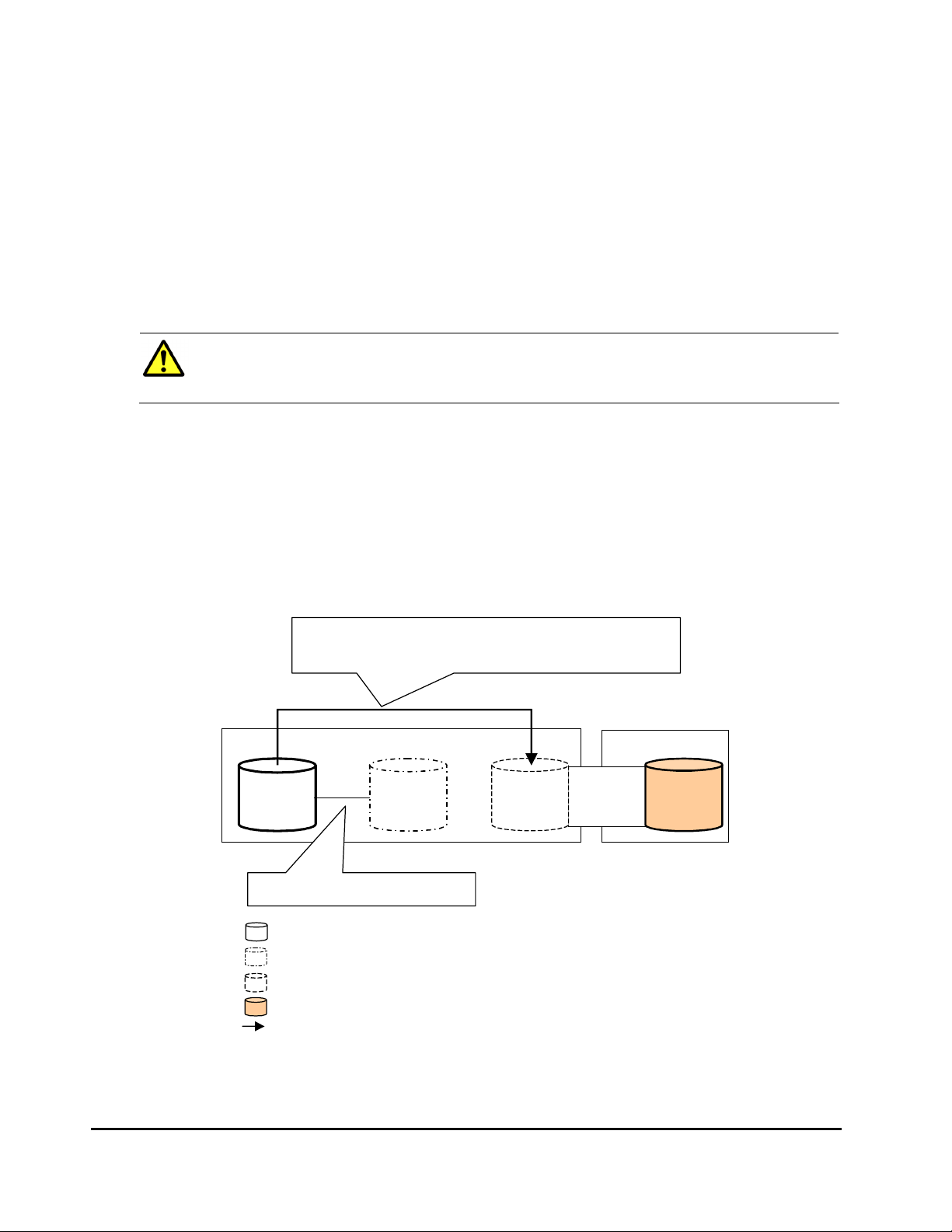
Copy-on-Write Snapshot Operations
A
Figure 2-16 shows the use of an external volume for the Copy-on-Write
Snapshot operation. The mapped external volume is set as a pool-VOL of the
Copy-on-Write Snapshot pair. For details on Copy-on-Write Snapshot, see the
Copy-on-Write Snapshot User’s Guide.
The procedure for the operation is as follows:
1. Use Universal Volume Manager to map a volume in the external storage
system as an internal volume of the local storage system.
Caution: Set the emulation type of the volume to OPEN-V when you map
the volume, because the volume with the OPEN-V emulation type can only
be set as a pool-VOL of Copy-on-Write Snapshot.
2. The status of the mapped volume automatically becomes Normal. However,
the volume formatting processing is not executed automatically. If you
need to format the mapped volume, format the volume using the VLL
function. For the volume formatting operation procedure, see the Virtual
LVI/LUN and Volume Shredder User's Guide.
3. Create a pool and add the mapped external volume to that pool as a poolVOL.
4. Set the P-VOL and S-VOL of the Copy-on-Write Snapshot pair with
specifying the pool you have created at the step 3.
Copy-on-Write
Snapshot
Creating a Copy-on-Write Snapshot pair.
Legend
s you create a Copy-on-Write Snapshot pair,
the data of the internal volume in the local storage system that is set as a
P-VOL is copied to the external volume that is set as a pool-VOL
Local Storage System
Copy-on-Write
P-VOL
: Internal v olume
: Virtual volume (S-VOL of the Copy-on-Write Snapshot pair)
: Internal volume where the external volume is mapped
: External volume
: Data copy direction
Snapshot
S-VOL
Copy-on-Write
Snapshot
Pool-VOL
Mapping
External Storage System
Figure 2-16 Example of the Copy-on-Write Snapshot Operation
2-36 About Universal Volume Manager Operations
Hitachi Universal Storage Platform V/VM Universal Volume Manager User’s Guide
Page 57

3
Preparing for Universal Volume
Manager Operations
This chapter describes the requirements and preparations for Universal
Volume Manager operations.
System Requirements
Guidelines for Universal Volume Manager Operations
Installing and Uninstalling Universal Volume Manager
Starting Universal Volume Manager
Preparing for Universal Volume Manager Operations 3-1
Hitachi Universal Storage Platform V/VM Universal Volume Manager User’s Guide
Page 58

System Requirements
The system requirements for Universal Volume Manager are:
• USP V/VM storage system (First storage system)
All the necessary hardware and microcode required for Universal Volume
Manager operations must be installed and enabled. In this user's guide, the
first storage system is called “local storage system”.
• Storage system other than the first storage system
A second storage system must be available and operated as an external
storage system. The kinds of storage systems that can be used as an
external storage system include the Lightning 9900V series storage system,
the Thunder 9500V series storage system, the Lightning 9900C series
storage system, and other similar storage systems.
• USP V/VM Storage Navigator computer (user-supplied computer)
See the Storage Navigator User’s Guide for instructions on installing and
using the Storage Navigator computer.
Note: You must operate the Storage Navigator computer in Modify mode
to perform Universal Volume Manager operations. Users in View mode can
only view Universal Volume Manager information.
• License key for Universal Volume Manager program product
You need a license key to install Universal Volume Manager.
Storage Systems Supported as External Storage Systems
Supported storage systems that can be connected as the external storage
system are shown in the following table. The table includes information on how
those storage systems are referenced in this document and in the Universal
Volume Manager windows.
Table 3-1 Storage Systems Available as External Storage Systems
Storage System Note
Universal Storage
Platform V
Universal Storage
Platform VM
TagmaStore Universal
Storage Platform
TagmaStore Network
Storage Controller
Displayed by Universal Volume Manager as “USP V”.
Path Mode of the cross-subsystem paths will be Multi.
Displayed by Universal Volume Manager as “USP VM”.
Path Mode of the cross-subsystem paths will be Multi.
Displayed by Universal Volume Manager “USP”.
Path Mode of the cross-subsystem paths will be Multi.
Displayed by Universal Volume Manager as “NSC”.
Path Mode of the cross-subsystem paths will be Multi.
3-2 Preparing for Universal Volume Manager Operations
Hitachi Universal Storage Platform V/VM Universal Volume Manager User’s Guide
Page 59

Storage System Note
TagmaStore Adaptable
Modular Storage
TagmaStore Workgroup
Modular Storage
Lightning 9900V series Displayed by Universal Volume Manager as “9970V” and “9980V”.
Thunder 9500V series Displayed by Universal Volume Manager as “9500V”.
Lightning 9900 series Lightning 9960 is displayed by Universal Volume Manager as “0400”.
A/H-6593 Displayed by Universal Volume Manager as “300”.
SANRISE Universal Storage
Platform
SANRISE Network Storage
Controller
SANRISE Adaptable Modular
Storage
SANRISE Workgroup
Modular Storage
SANRISE 9900V series Displayed by Universal Volume Manager as “9970V” and “9980V”.
SANRISE 9500V series Displayed by Universal Volume Manager as “9500V”.
SANRISE 2000 series SANRISE 2800 is displayed by Universal Volume Manager as “0400”.
H24000 Displayed by Universal Volume Manager as “24000”.
H20000 Displayed by Universal Volume Manager as “20000”.
SANRISE H12000 Displayed by Universal Volume Manager as “12000”.
SANRISE H10000 Displayed by Universal Volume Manager as “10000”.
SANRISE H1024/H128 Displayed by Universal Volume Manager as “1024” and “128”.
SANRISE H512/H48 Displayed by Universal Volume Manager as “512” and “48”.
Displayed by Universal Volume Manager as “AMS”.
Path Mode of the cross-subsystem paths will be Single.
Displayed by Universal Volume Manager as “WMS”.
Path Mode of the cross-subsystem paths will be Single.
Path Mode of the cross-subsystem paths will be Multi.
Path Mode of the cross-subsystem paths will be Single.
Lightning 9910 is displayed by Universal Volume Manager as “0401”.
Path Mode of the cross-subsystem paths will be Multi.
Path Mode of the cross-subsystem paths will be Multi.
Displayed by Universal Volume Manager as “USP”.
Path Mode of the cross-subsystem paths will be Multi.
Displayed by Universal Volume Manager as “NSC”.
Path Mode of the cross-subsystem paths will be Multi.
Displayed by Universal Volume Manager as “AMS”.
Path Mode of the cross-subsystem paths will be Single.
Displayed by Universal Volume Manager as “WMS”.
Path Mode of the cross-subsystem paths will be Single.
Path Mode of the cross-subsystem paths will be Multi.
Path Mode of the cross-subsystem paths will be Single.
SANRISE 2200 is displayed by Universal Volume Manager as “0401”.
Path Mode of the cross-subsystem paths will be Multi.
Path Mode of the cross-subsystem paths will be Multi.
Path Mode of the cross-subsystem paths will be Multi.
Path Mode of the cross-subsystem paths will be Multi.
Path Mode of the cross-subsystem paths will be Multi.
Path Mode of the cross-subsystem paths will be Multi.
Path Mode of the cross-subsystem paths will be Multi.
Preparing for Universal Volume Manager Operations 3-3
Hitachi Universal Storage Platform V/VM Universal Volume Manager User’s Guide
Page 60

Storage System Note
SANRISE H256 Displayed by Universal Volume Manager as “256”.
Path Mode of the cross-subsystem paths will be Multi.
XP24000 Displayed by Universal Volume Manager as “24000”.
Path Mode of the cross-subsystem paths will be Multi.
XP20000 Displayed by Universal Volume Manager as “20000”.
Path Mode of the cross-subsystem paths will be Multi.
XP12000 Displayed by Universal Volume Manager as “12000”.
Path Mode of the cross-subsystem paths will be Multi.
XP10000 Displayed by Universal Volume Manager as “10000”.
Path Mode of the cross-subsystem paths will be Multi.
XP1024/XP128 Displayed by Universal Volume Manager as “1024” and “128”.
Path Mode of the cross-subsystem paths will be Multi.
XP512/XP48 Displayed by Universal Volume Manager as “512” and “48”.
Path Mode of the cross-subsystem paths will be Multi.
XP256 Displayed by Universal Volume Manager as “256”.
Path Mode of the cross-subsystem paths will be Multi.
SVS200 Displayed by Universal Volume Manager as “SVS200”.
Path Mode of the cross-subsystem paths will be Multi.
HP StorageWorks Enterprise
Virtual Array
3000/4000/5000/6000/800
0
IBM storage system For the type of the supported storage system, call the Support Center.
EMC storage system For the type of the supported storage system, call the Support Center.
Fujitsu storage system For the type of the supported storage system, call the Support Center.
NEC storage system For the type of the supported storage system, call the Support Center.
Displayed by Universal Volume Manager as “EVA”.
Path Mode of the cross-subsystem paths will be Single.
3-4 Preparing for Universal Volume Manager Operations
Hitachi Universal Storage Platform V/VM Universal Volume Manager User’s Guide
Page 61

Universal Volume Manager Requirements
The following table describes the Universal Volume Manager requirements.
Table 3-2 Universal Volume Manager Requirements
Item Requirement
Maximum number of ports in the
connected external storage system
(WWN is used as a port identification
number)
Maximum number of external volumes
which can be connected
Maximum number of mapping paths
can be set for one external volume
Maximum capacity of an external
volume
Minimum capacity of an external
volume
Maximum number of external volume
groups
Maximum number of external volumes
which can be registered in one
external volume group
1,024 per port
63,232 volumes can be connected..
4,096 volumes can be connected per port.
Note: If you use Copy-on-Write Snapshot or Dynamic
Provisioning, the number of external volumes which can be
connected is as follows:
Number of external volumes + Number of virtual volumes ≤
63,232
8
4 TB per external volume (8,589,934,592 blocks)
If you specify an external volume which is more than 4 TB you
can access the data stored in the field up to 4 TB. You cannot
access the data that is stored in the field over 4 TB.
77,760 blocks (about 38 MB) per external volume.
However, when the emulation type of the volume is OPEN-V,
the minimum capacity becomes 96,000 blocks (about 47 MB)
per external volume
16,384
4,096
Preparing for Universal Volume Manager Operations 3-5
Hitachi Universal Storage Platform V/VM Universal Volume Manager User’s Guide
Page 62

Guidelines for Universal Volume Manager Operations
This section provides guidelines for the Universal Volume Manager operations.
Mapping Guidelines
• Before mapping external volumes, make sure that external volumes are
not reserved by a host.
External volumes that are reserved by a host cannot be mapped as internal
volumes. If external volumes are reserved by a host, cancel the reserve
settings and then map the external volumes.
• Once external volumes are mapped, do not reserve the external volumes
for a host .
If external volumes are reserved by a host , internal volumes to which the
external volumes are mapped will be blocked .
• Make sure that an external volume is accessed only from the local storage
system side once the external volume is mapped.
– Make sure that the external volume, which has been mapped as an
internal volume, is not accessed from the host that is connected to the
external storage system.
– Make sure that the external volume, which has been mapped as an
internal volume, is not manipulated by copy function or some other
functions of the external storage system.
Hosts can access the external storage system volumes that have not been
mapped as the internal volumes. There is no restriction.
• Do not map multiplatform volumes of external storage systems as internal
volumes.
• When an external storage system that has an ownership is connected to
USP V/VM storage system, configure the cross-subsystem path to the
primary controller in the external storage system as primary path.
Ownership is an exclusive right to control volumes. A controller that has an
ownership is called a primary controller. If a cross-subsystem path to a
controller without ownership is configured as primary path, the ownership
will be transferred and it may affect the performance.
3-6 Preparing for Universal Volume Manager Operations
Hitachi Universal Storage Platform V/VM Universal Volume Manager User’s Guide
Page 63

Recommended Applications according to the HDD Type
Table 3-3 and Table 3-4 show the recommended level of the application of
mapped external volume according to the HDD type of the external volume.
Table 3-3 When the Emulation Type of the External Volume is for OPEN
Application HDD Type
FC SATA
Database
Online Transaction Processing
(OLTP)
File Operation from Host
(Both of Read and Write)
File Operation from Host
(Mainly Read)
Backup OK Recommended
Archive OK Recommended
Not Recommended Not Recommended
OK Not Recommended
OK OK
Table 3-4 When the Emulation Type of the External Volume is for
Mainframe
Application HDD Type
FC SATA
Database
Online Transaction Processing
(OLTP)
System Volumes
(Journal, Check points)
Operation from TPF Not Supported Not Supported
File Operation from Host
(Both of Read and Write)
File Operation from Host
(Mainly Read)
Backup OK Recommended
Archive OK Recommended
Not Recommended Not Recommended
Not Recommended Not Recommended
OK Not Recommended
OK OK
Preparing for Universal Volume Manager Operations 3-7
Hitachi Universal Storage Platform V/VM Universal Volume Manager User’s Guide
Page 64

Capacity Guidelines
• When a volume, which has the capacity of 4 TB or less, in the external
storage system (external volume) is mapped with the setting of OPEN-V
emulation type, the volume is defined as the internal volume that has the
same capacity as the mapped external volume.
・
・
External Volume
The capacity is 4 TB or less.
OPEN-V emulation type
LDEV LU
Figure 3-1 Example of External Volume of 4 TB or Less
• You cannot access the data that is stored in the field over the maximum
capacity of the external volume. The maximum volume capacity differs
depending on the emulation type that you specify at the external volume
mapping.
• When an external volume is mapped as internal volume(s) with the setting
of the emulation type other than OPEN-V, the number of volumes and the
volume capacity of the mapped external volume(s) depend on the capacity
of the original external volume and the basic capacity of each emulation
type. When an external volume is mapped with the setting of emulation
type other than OPEN-V, the data management information area is
required to be provided in the mapped volume. This means that the
capacity that can be used after the mapping becomes smaller than the
actual external volume capacity. The available capacity decreases as much
capacity as the data management information area.
Figure 3-2 shows an example of the case that the original capacity of the
external volume is bigger than the basic capacity of the emulation type.
The emulation type is OPEN-3.
that the original capacity of the external volume is smaller than the basic
capacity of the emulation type.
3-8 Preparing for Universal Volume Manager Operations
Hitachi Universal Storage Platform V/VM Universal Volume Manager User’s Guide
Figure 3-3 shows an example of the case
Page 65

External Volume
Free Space
(The area less than the basic
capacity of emulation type
remains as free space)
6 GB
VDEV LDEV LU
OPEN-3
Area provided to store data
management information
Figure 3-2 When the External Volume Capacity is Bigger than the
Basic Capacity of Specified Emulation Type (Example of
the OPEN-3 emulation type)
2 GB
VDEV LDEV LU External Volume
Figure 3-3 When the External Volume Capacity is Smaller than the
Basic Capacity of Specified Emulation Type
Guidelines for Mainframe Volumes
• If you plan to use the mapped external volume from the mainframe OS
(e.g., the volume is mapped with the setting of 3390-x mainframe
emulation type), you need to select the external volume that consists of
one LDEV or you need to adjust the capacity of the external volume to be
mapped beforehand.
Area provided to store data
management information
• If multiple LDEVs exist in one external volume and if a lot of I/Os are made
to these LDEVs, the read, write commands may become timeout. When the
commands become timeout, the SIM (21D2xx) is reported.
Preparing for Universal Volume Manager Operations 3-9
Hitachi Universal Storage Platform V/VM Universal Volume Manager User’s Guide
Page 66

• When you use the mapped external volume from the mainframe OS, set
the MIH (M
recommended value).
issing Interrupt Handler) timer to 45 seconds (which is the
Volume Attribute Guidelines
• The external volume attributes for all the LDEVs created in an external
volume become the same. The attributes are taken over, when the LDEVs
are reconfigured using the VLL function.
• The Cache Mode becomes the same for all the LDEVs in one external
volume.
• The attributes that are set for the external volume originally on the
external storage system side (such as the port security, the LUN security,
the Volume Retention Manager attributes, and so on) are not kept, when
the external volume is mapped as an internal volume. If the original
attributes are required to be set, set the attributes on the mapped external
volume from the local storage system side.
• For the external volume, for which the Cache Mode is set to Disable, the
bind mode for the Cache Residency Manager operation is not available.
• If you use the mapped external volume for the Cache Residency Manager
operation and set the bind mode, the cache of twice as much capacity as
the user data is required for the Cache Residency Manager operation.
Creating LUSE Volume Guidelines
• Do not combine LDEVs of multiple external volumes to create a LUSE
volume. The LDEVs in the same external volume can only be used to set
the LUSE volumes.
• When you combine LDEVs of multiple external volumes to create a LUSE
volume, you need to consider:
– If a LUSE volume consists of multiple external volumes and one
external volume has lower performance than the other volumes, the
lower performance of the volume affects the performance of the LUSE
volume.
– When an external volume which is a component of a LUSE volume is
blocked, data reliability of the LUSE volume will deteriorate because the
LUSE volume has both accessible area and inaccessible area from a
host.
– When you disconnect an external volume or resume the use of an
external volume, you need to perform the operation at the same time
on all the external volumes which are components of the LUSE volume.
• The mapped volumes that have different cache mode settings cannot be
used to create one LUSE volume.
3-10 Preparing for Universal Volume Manager Operations
Hitachi Universal Storage Platform V/VM Universal Volume Manager User’s Guide
Page 67

VMA of Data Retention Utility
• If you map an external volume to which the volume management area
(VMA) of Data Retention Utility is set, you need to configure system
options before performing the port discovery or volume discovery operation
to validate the VMA information. Please call the Hitachi Data Systems
Support Center to find out about how to configure system options (see
Calling the Hitachi Data Systems Support Center).
• If you have previously mapped a TagmaStore USP volume and set the VMA
of Data Retention Utility in that volume, the VMA setting is inherited when
you map the volume again.
Maintenance Guidelines for an External Storage System
• Before you change settings of the external storage system, you must
delete the external volume mapping. After you change settings of the
external storage system, you must remap the external volume. If you do
not remap the volume, the external volume cannot be used in the local
storage system.
The examples of external storage system settings which require the remapping of external volume are as follows:
– Changing WWNs of target ports which connect to the local storage
system
– Changing the serial number of the external storage system
– Changing LUNs of volumes of the external storage system
– Reducing the volume capacity of the external storage system so that
the volume capacity is smaller than when volume mapping was
performed
Besides, re-mapping is required for Universal Volume Manager after you
change external storage system settings that require modification on the
host side when hosts are connected directly to a external storage system.
Before you delete the external volume mapping, make sure that the
volume has no LU paths, and that the volume is not a component of any
pairs (such as TrueCopy pairs).
Performance and Status Guidelines
• The performance and status of the external storage system affect the Read
and Write performance of the mapped external volume. If there is a heavy
load on the external storage system, the processing speed of the Read and
Write operation becomes slow. In this case, the I/Os from the mainframe
host may become MIH error.
• If the host connected to the local storage system issues too many I/Os to
be processed by the external storage system, the commands from the host
may possibly be timed out.
Preparing for Universal Volume Manager Operations 3-11
Hitachi Universal Storage Platform V/VM Universal Volume Manager User’s Guide
Page 68

When the amount of I/Os from the host to the external volume exceeds the
maximum amount of I/Os that the external storage system can accept, the
commands from the host to the local storage system may possibly be
timed out. As you configure the system using the external volumes,
consider the capability for the I/O amount of the external storage system.
• When you execute the commands of the USP V/VM program products to
the mapped external volume and thus too many I/Os are issued to be
processed by the external storage system, the commands may possibly be
timed out and an error may occur.
When the amount of I/Os from the program products to the external
volume exceeds the maximum amount of I/Os that the external storage
system can accept, the commands from the program products may
possibly be timed out and an error may occur. As you configure the system
using the external volumes, consider the capability for the I/O amount of
the external storage system.
• When you use an external volume from the host, note the Path Blockade
Watch time for the external volume. If the Path Blockade Watch time is
longer than the timeout period of the host command, the commands from
the host may possibly be timed out when the power supply is off or when
an error occurs for the external storage system. If the host I/O is a
significant concern, make sure that the Path Blockade Watch time of the
external volume is the same as or shorter than the timeout period of the
host command.
RAID Level Considerations
In the internal processing, the RAID level of the external volume is handled as
RAID-1 across the board. The bar (−) is displayed on the Storage Navigator
windows. The RAID level of external volumes is reported as RAID-1 when
information about external storage system is reported to the higher-level
device (OS).
Thunder 9500V Series Guidelines
When you use the Thunder 9500V series storage system as an external
storage system, the following versions are recommended. If you use a 9500V
storage system whose version is earlier than the following versions, the
information about the SATA drive may not be displayed correctly.
• For Thunder 9530V, Thunder 9520V, Thunder 9570V: version 0658 or
later.
• For Thunder 9580V, Thunder 9585V: version 1658 or later.
3-12 Preparing for Universal Volume Manager Operations
Hitachi Universal Storage Platform V/VM Universal Volume Manager User’s Guide
Page 69

Installing and Uninstalling Universal Volume Manager
This section explains how to install and uninstall Universal Volume Manager.
Installing Universal Volume Manager
You need to install Universal Volume Manager using the license key to perform
the Universal Volume Manager operations on the Storage Navigator computer.
To install the Universal Volume Manager license key:
1. Start the Storage Navigator Java applet for the desired storage system.
2. Enable the Universal Volume Manager options on the Storage Navigator
computer and on each storage system.
For detailed instructions, see the Storage Navigator User’s Guide.
Uninstalling Universal Volume Manager
To uninstall Universal Volume Manager, you must cancel all the pairs and then
delete the external volume mapping.
To uninstall Universal Volume Manager:
1. Start Storage Navigator, and open the Storage Navigator main window.
For instructions, see the Storage Navigator User’s Guide.
2. Delete external volume mapping.
3. Disable the Universal Volume Manager option on the Storage Navigator
computer and on each storage system.
For detailed information about the un-installation procedure, see the
Storage Navigator User’s Guide.
Preparing for Universal Volume Manager Operations 3-13
Hitachi Universal Storage Platform V/VM Universal Volume Manager User’s Guide
Page 70

Starting Universal Volume Manager
This section explains how to start Universal Volume Manager.
To start Universal Volume Manager and display the window:
1. Start Storage Navigator, and open the Storage Navigator main window.
For instructions, see the Storage Navigator User’s Guide.
2. Click Go and then Universal Volume Manager on the menu bar of the
Storage Navigator main window.
Names of the windows that you need for Universal Volume Manager
operations are available in the submenu.
3. Click the name of the window you want to display.
Universal Volume Manager starts up, and the window you selected is
displayed.
4. Switch to Modify mode if necessary.
For instructions, see the Storage Navigator User’s Guide.
3-14 Preparing for Universal Volume Manager Operations
Hitachi Universal Storage Platform V/VM Universal Volume Manager User’s Guide
Page 71

4
Using the Universal Volume Manager
GUI
This chapter explains the Universal Volume Manager windows. Universal
Volume Manager involves the Volume Operation window, the Path Operation
window and the Port Operation window. When you click the tab of the window
name, the window is switched to the corresponding window.
Volume Operation Window
Path Operation Window
Port Operation Window
Using the Universal Volume Manager GUI 4-1
Hitachi Universal Storage Platform V/VM Universal Volume Manager User’s Guide
Page 72

Volume Operation Window
The Volume Operation window enables you to perform the operations, such as
mapping external volumes and setting cross-subsystem paths. To display the
Volume Operation window, click Go, Universal Volume Manager, and then
Volume Operation on the menu bar of the Storage Navigator main window.
Figure 4-1 Volume Operation Window
The Volume Operation window consists of:
• Volume Operation Tree (left of the window)
The left pane of the window is composed of a tree, and a drop-down list
which is used to switch the display of the tree. The contents displayed in
the list (right of the window) switch corresponding to the items selected in
the tree.
• Status: Disable button or Status: Enable button (upper right of the
window)
When you click Status: Disable, the button name changes to Status:
Enable and you can display the external volume status in the Ext. VOL
Status column in the Volume Operation list.
4-2 Using the Universal Volume Manager GUI
Hitachi Universal Storage Platform V/VM Universal Volume Manager User’s Guide
Page 73

The Ext. VOL Status column does not display any status when you open
the Volume Operation window, because to display the external volume
status takes longer than displaying other items in the window.
Note: To update the all items in the window including the Ext. VOL Status
column, make sure the button name is Status: Enable, then click File and
Refresh on the menu bar of the Storage Navigator main window.
• Volume Operation List (right of the window)
Information on the local storage system and external storage system is
displayed corresponding to the items selected in the tree.
The list can be sorted by the displayed items. For instance, if you want to
sort the list in the order of LDEV numbers, click LDEV on the list.
The items clicked in the tree and the information displayed in the list are as
follows:
Table 4-1 Volume Operation Tree
Items
selected in
the list
Fibre
Items displayed in
the tree
(Clicked items are
underlined)
Subsystem
+ Product name
+ Path group
Subsystem
+ Product name
+ Path group
Subsystem
+ Product name
+ Path group
Contents displayed in the list Reference
Information about the external storage
system. The same contents are
displayed when you click the product
name in the tree.
Information about the external storage
system. The same contents are
displayed when you click the
Subsystem in the tree.
The list of external volumes and crosssubsystem paths which are set in the
selected path group.
Volume Operation
List (When
Subsystem or
Product Name is
Clicked)
Volume Operation
List (When Path
Group is Clicked)
• Operation (lower left of the window)
The name of the performed setting operation is displayed. You can check
the details in the Preview dialog box by clicking the Preview button.
• Preview button (lower right of the window)
When you click Preview, the
confirm the contents which was set in the list of the Volume Operation
window. The contents displayed in the Preview dialog box have not been
applied to the local storage system, yet.
Preview dialog box is displayed and you can
• Apply button
Applies the settings in the Preview dialog box to the local storage system.
When the settings are applied successfully, they are removed from the
Preview dialog box and the settings in blue and italics in the Volume
Operation window is displayed normally.
Using the Universal Volume Manager GUI 4-3
Hitachi Universal Storage Platform V/VM Universal Volume Manager User’s Guide
Page 74

When the settings are not applied, the error messages are displayed and
the settings in blue and italics remain displayed in the Volume Operation
window. To refer to the error detail, click Preview to open the Preview
dialog box.
• Cancel button
Cancels all the settings in the Preview dialog box.
Volume Operation Tree
The Volume Operation tree is a tree on the left side of the Volume Operation
window consisting of a tree and a drop-down list which is used to switch the
display of the tree.
The Volume Operation tree consists of:
• Drop-down list
A drop-down list to switch the items displayed in the Volume Operation
tree. You can select Fibre from the drop-down list as a PCB type.
• Tree
The following items are displayed in tree format. The contents displayed in
the list (right of the window) switch corresponding to the items clicked in
this tree. For details, see
Table 4-1.
– Subsystem: The root node of the Volume Operation tree which is
always displayed.
– Product name of the external volume: The product name of the external
storage system whose volumes are mapped by Universal Volume
Manager is displayed below Subsystem. The display format is "Vendor
name: Product name (Serial number)".
– Path group: The path group set in the external storage system is
displayed under the product name of the external storage system.
When multiple path groups are set, the registration numbers are added
after the "Path Group" (Example: Path Group 2).
• Pop-up menu
Right-click the item in the Volume Operation tree to perform the following
operations from the pop-up menu.
4-4 Using the Universal Volume Manager GUI
Hitachi Universal Storage Platform V/VM Universal Volume Manager User’s Guide
Page 75

Table 4-2 Pop-up Menu for the Volume Operation Tree
Items displayed in
Tree
(clicked items are
underlined)
Subsystem
+ Product name
+ Path group
Edit Policy
Subsystem
+ Product name
+ Path group
Subsystem
+ Product name
+ Path group
Pop-up Menu Description
Add Volume (Auto)
Add Volume
(Manual)
Disconnect
Subsystem
Check Paths &
Restore Volume
Add Volume (Auto)
Add Volume
(Manual)
Displays the Configure Cross-subsystem Paths dialog
box or the Add Volume (Manual) dialog box. These
dialog boxes allow you to set a new path group, and
add external volumes to the new path group.
Displays the Edit Policy dialog box. This dialog box
allows you to edit the mapping policy.
Disconnects or reconnects the external volumes in
the selected external storage system.
The Volume Discovery is executed and all the
external volumes found by the Volume Discovery are
displayed in the following windows.
For the Add Volume (Auto) command:
Volume Operation window
For the Add Volume (Manual) command:
Add Volume dialog box
Volume Operation List (When Subsystem or Product Name is Clicked)
When you click Subsystem or a product name in the Volume Operation tree,
the external storage system information is displayed in the list.
Figure 4-2 Volume Operation List when Subsystem or a Product Name
is Clicked
The Volume Operation list consists of:
• External Subsystem
The following items are displayed:
– Vendor: Name of the vendor.
– Product Name: Name of the storage system.
– Serial Number: Serial number of the storage system.
Using the Universal Volume Manager GUI 4-5
Hitachi Universal Storage Platform V/VM Universal Volume Manager User’s Guide
Page 76

– Ext. VOL Status: Status of the operation executed to the external
volume or status of the connection of the mapping path. The displayed
items are shown in the following table. To check status of each LDEV in
the external volume, you need to view the VLL window.
Table 4-3 Status of the External Volume Displayed in the Ext. VOL Status
Displayed Item Description
Normal The path is normal.
-
Unknown The status of the mapping path is unknown.
Blockade The mapping path is blocked.
Warning
Checking The processing of checking the mapping path status is in progress.
Cache Destage
Disconnect
The status of the mapping path is not retrieved yet. Click Status: Disable
in the Volume Operation window to display the status of the mapping path.
There are mapping paths whose status is not normal. Check the status of
the mapping paths in the Mapping Path Information dialog box.
The writing processing of all the data in cache memory to the volume is in
progress.
Connecting to the external storage system or the external volume is
intentionally stopped using the Disconnect Subsystem command or the
Disconnect Volume command.
• Information Area
Information according to the contents of the External Subsystem on the
Volume Operation window is displayed in the information area, as follows:
– Total Number of Ext. Subsystems: the number of external storage
systems that have the mapped external volumes.
– Total Number of Ext. Volumes: the number of the mapped external
volumes and the number of the external volumes that can be mapped.
• Pop-up menu
The External Subsystem does not have a pop-up menu that can be
displayed.
Volume Operation List (When Path Group is Clicked)
When you click a path group in the Volume Operation tree, the external
storage system information and the cross-subsystem path information is
displayed in the list.
4-6 Using the Universal Volume Manager GUI
Hitachi Universal Storage Platform V/VM Universal Volume Manager User’s Guide
Page 77

Figure 4-3 Volume Operation List when Path Group is Clicked
The Volume Operation list consists of:
• External Volumes
The following items are displayed:
– ExG: external volume group number and sequential number assigned
to each volume in the external volume group. This is displayed in the
format of “external volume group number - sequential number of
volume in the group”. The sequential numbers of volumes in the group
are automatically assigned by Universal Volume Manager when the
external volumes are mapped.
– LDEV: LDKC:CU:LDEV number* which is assigned to the external
volume. When multiple LDEVs are created in the external volume, the
top LDEV number is displayed, and [...] is displayed at the end of the
number.
* LDKC: Logical Disk Controller
CU: Control Unit
– Characteristic1: identification number of the external volume.
– Device: name of the storage system that is reported to the host by the
external volume. The displayed items differs depending on the vendor
of the storage system.
Using the Universal Volume Manager GUI 4-7
Hitachi Universal Storage Platform V/VM Universal Volume Manager User’s Guide
Page 78

– Capacity (blocks): capacity of the external volume in Blocks.
– Cache Mode: displays whether the write data from the host to the
external storage system is propagated synchronously (Disable) or
asynchronously (Enable). Data that is not written by the host (for
example, data written by ShadowImage) is asynchronously destaged to
the external storage system regardless of the Cache Mode setting.
– Inflow Control: displays whether the writing operation to the cache
memory is stopped (Enable) or continued (Disable) when the writing
operation to the external volume is impossible.
– Path Mode: Indicates how the cross-subsystem paths work. The
displayed modes of the cross-subsystem path are as follows:
– Single: For the Single mode, the only cross-subsystem path with
the highest priority (primary path) is used to execute the I/O to the
external volume. When an error occurred in the primary path, the
path with the second highest priority is used.
– Multi: For the Multi mode, all of the cross-subsystem paths that
you configured are used at the same time. The multiple paths are
used to execute the I/Os to the external volume distributing the
work load.
– Ext. VOL Info: information about the external volume. When the
external volume is an SATA drive of the TagmaStore AMS/WMS storage
system or the Thunder 9500V series storage system, “ * ” is displayed.
For the operation of the SATA drive, follow the method of the
TagmaStore AMS/WMS or Thunder 9500V storage system.
– Ext. VOL Status: status of the operation executed to the external
volume or status of the connection of the mapping path. For the
displayed status descriptions, see
LDEV in the external volume, you need to view the VLL window.
Table 4-3. To check status of each
– Progress: displays when the Status is Cache Destage. The progress
status of destaging processing is displayed in 1 % to 99 %.
– Characteristic2: extended identification number of the external
volume. This information is used for identifying volumes in the EVA
storage system.
• Cross-subsystem Paths
The following items are displayed:
– Priority: Priority of the cross-subsystem paths. “1” indicates the cross-
subsystem path with the highest priority.
– Port: The port number in the local storage system connecting to the
external storage system.
– WWN: Identification number of the port in the external storage system.
• Pop-up Menu
Right-click a row in the External Volumes (at the top of the window) to
perform the following operations from the pop-up menu.
4-8 Using the Universal Volume Manager GUI
Hitachi Universal Storage Platform V/VM Universal Volume Manager User’s Guide
Page 79

Table 4-4 Pop-up Menu: External Volumes, Volume Operation Window
Pop-up Menu Description
Mapping Path Information
LDEV Information
Delete Volume Cancels the mapping of the selected external volume.
Disconnect Volume Disconnects the selected external volume.
Check Paths & Restore
Volume
Change Cache Mode Changes the cache mode set to the selected external volume.
Inflow Control
Displays the Mapping Path Information dialog box. This dialog box
allows you to refer to the list of the mapping paths set to the selected
external volume.
Displays the LDEV Information dialog box. This dialog box allows you
to refer to the emulation type and the capacity of the selected external
volume.
Reconnects the selected external volume.
Allows you to select whether to stop writing to the cache memory
when it is impossible to write to the selected external volume.
Right-click a row in the Cross-subsystem Paths (at the bottom of the
window) to perform the following operations from the pop-up menu.
Table 4-5 Pop-up Menu: Cross-Subsystem Paths, Volume Operation
Window
Pop-up menu Description
Configure Cross-Subsystem
Paths
Displays the Configure Cross-subsystem Paths dialog box. This dialog
box allows you to add and delete cross-subsystem paths, and also
change the priority of the selected cross-subsystem path.
Using the Universal Volume Manager GUI 4-9
Hitachi Universal Storage Platform V/VM Universal Volume Manager User’s Guide
Page 80

Preview Dialog Box
The Preview dialog box allows you to check or cancel the settings that will be
applied to the local storage system. To display the Preview dialog box, click
Preview in the Volume Operation window, the Path Operation window, or the
Port Operation window. This document uses the term "the Universal Volume
Manager windows" to call these three windows.
The contents displayed in the Preview dialog box are displayed in blue italics
in the list of the Universal Volume Manager windows. The contents displayed in
the Preview dialog box have not been applied to the local storage system, yet.
When you click Apply on the Universal Volume Manager windows, the settings
in the Preview dialog box are applied to the local storage system. When the
settings are applied, the contents of the Preview dialog box disappear, and the
list of the Universal Volume Manager windows is displayed normally. When you
click Cancel on the Universal Volume Manager windows, all the settings in the
Preview dialog box are canceled.
When the settings in the Preview dialog box are not applied to the local
storage system even if you click Apply on the Universal Volume Manager
windows, an error message is displayed and the erroneous settings are
displayed in blue and italics in the Universal Volume Manager windows. To
refer to the error detail, click Preview to open the Preview dialog box.
Note: The identical error codes may be displayed for all the errors listed in the
Preview dialog box depending on the type of errors occurred. In this case,
check the status of settings and identify the error source.
Figure 4-4 Preview Dialog Box
4-10 Using the Universal Volume Manager GUI
Hitachi Universal Storage Platform V/VM Universal Volume Manager User’s Guide
Page 81

The Preview dialog box consists of:
• Preview Area
The items set in the list of the Universal Volume Manager windows are
displayed. The contents displayed in the preset area differ depending on
the items set in the list of the Universal Volume Manager windows. The
contents displayed in the preset area are displayed in blue italics in the
list of the Universal Volume Manager windows.
• Operation Information Area
The operation information on the settings displayed in the Preview dialog
box is displayed in the operation information area. Following information is
displayed:
– Operation: name of the setting operation.
– Total Number of Objects in Preview: the number of settings
displayed in the Preview dialog box.
• Close button
The Preview dialog box closes, and returns to the Universal Volume
Manager windows.
• Pop-up menu
Right-click a row in the Preview dialog box to perform the following
operations from the pop-up menu.
– Error Message: Displays the error message of the selected setting.
– Delete: Cancels the settings selected in the Preview dialog box.
Using the Universal Volume Manager GUI 4-11
Hitachi Universal Storage Platform V/VM Universal Volume Manager User’s Guide
Page 82

Path Operation Window
The Path Operation window enables you to stop or resume using crosssubsystem paths. To display the Path Operation window, click Go, Universal
Volume Manager, and then Path Operation on the menu bar of the Storage
Navigator main window.
Figure 4-5 Path Operation Window
The Path Operation window consists of:
• Path Operation Tree (left of the window)
The left pane of the window is composed of a tree, and a drop-down list
which is used to switch the display of the tree. The contents displayed in
the list (right of the window) change corresponding to the items selected in
the tree.
• Status: Disable button or Status: Enable button (upper right of the
window)
When you click Status: Disable, the button name changes to Status:
Enable and you can display the cross-subsystem path status in the Status
column in the Path Operation list.
4-12 Using the Universal Volume Manager GUI
Hitachi Universal Storage Platform V/VM Universal Volume Manager User’s Guide
Page 83

The Status column does not display any status when you open the Path
Operation window, because to display the cross-subsystem path status
takes longer than displaying other items in the window.
Note: To update the all items in the window including the Status column,
make sure the button name is Status: Enable, then click File and Refresh
on the menu bar of the Storage Navigator main window.
• List (right of the window)
Information on the local storage system and external storage system is
displayed corresponding to the items selected in the tree.
The list can be sorted by the displayed items. For instance, if you want to
sort the list in the order of port numbers, click Port on the list.
The items clicked in the tree and the information displayed in the list are as
follows:
Table 4-6 Path Operation Tree
Items selected
in the list
Fibre -Local
Subsystem
Fibre External
Subsystem
Items displayed in the
Subsystem
+ Port number
Subsystem
+ Port number
Product name
+ WWN
Product name
+ WWN
tree
(Clicked items are
underlined)
Contents displayed in the list Reference
External ports of the local storage
system.
Cross-subsystem paths which are set
to the selected external ports of the
local storage system.
The same contents are displayed
when you click the WWN in the tree.
WWNs of the external storage
system.
Cross-subsystem paths which are set
to the selected WWN of the external
storage system.
The same contents are displayed
when you click the port number in
the tree.
Path Operation List
(When Subsystem is
Clicked)
Path Operation List
(When Port or WWN
is Clicked)
Path Operation List
(When Product
Name is Clicked)
Path Operation List
(When Port or WWN
is Clicked)
• Operation (lower left of the window)
The name of the performed setting operation is displayed. You can check
the details in the Preview dialog box by clicking the Preview button.
• Preview button (lower right of the window)
When you click Preview, the Preview dialog box is displayed and you can
confirm the contents, which was set in the list of the Path Operation
window. The contents displayed in the Preview dialog box have not been
applied to the local storage system, yet.
Using the Universal Volume Manager GUI 4-13
Hitachi Universal Storage Platform V/VM Universal Volume Manager User’s Guide
Page 84

• Apply button
Applies the settings in the Preview dialog box to the local storage system.
When the settings are applied successfully, they are removed from the
Preview dialog box and the settings in blue and italics in the Path Operation
window is displayed normally.
When the settings are not applied, the error messages are displayed and
the settings in blue and italics remain displayed in the Port Operation
window. To refer to the error detail, click Preview to open the Preview
dialog box.
• Cancel button
Cancels all the settings in the Preview dialog box.
Path Operation Tree
The Path Operation tree is a tree on the left side of the Path Operation window
consisting of a tree and a drop-down list which is used to switch the display of
the tree.
The Path Operation tree consists of:
• Drop-down list
A drop-down list to switch the items displayed in the Path Operation tree.
You can select which side to display the information on cross-subsystem
paths from.
– Fibre - Local Subsystem: Displays ports in the local storage system.
– Fibre - External Subsystem: Displays ports (WWNs) in the external
storage system.
• Tree
The following items are displayed in tree format. The contents displayed in
the list (right of the window) change corresponding to the items clicked in
this tree. For details, see
When you select Fibre - Local Subsystem from the drop-down list, the
following items are displayed in the tree:
– Subsystem: The root node of the Path Operation tree which is always
displayed.
– Port number: The port number of the local storage system, which the
port attribute is set to External, is displayed below Subsystem. One of
the following icons is displayed:
–
: Ports in the Standard mode.
–
: Ports in the Initiator/External MIX mode.
Table 4-1.
4-14 Using the Universal Volume Manager GUI
Hitachi Universal Storage Platform V/VM Universal Volume Manager User’s Guide
Page 85

When you select Fibre - External Subsystem from the drop-down list,
the following items are displayed in the tree:
– Product name of the external volume: The product name of the external
storage system which is connected by Universal Volume Manager is
displayed as a root node. The display format is "Vendor name: Product
name (Serial number)".
– WWN: The WWNs of the external storage system is displayed below the
product name of the external storage system.
• Pop-up menu
The Path Operation tree does not have a pop-up menu that can be
displayed.
Path Operation List (When Subsystem is Clicked)
When you click Subsystem in the Path Operation tree, the external port
information which is set to the local storage system is displayed in the list.
Figure 4-6 Path Operation List when Subsystem is Clicked
The Path Operation list consists of:
• Port
The following items are displayed:
– Port: The external port of the local storage system. One of the
following icons is displayed:
–
: Ports in the Standard mode.
–
: Ports in the Initiator/External MIX mode.
– PLI_TOV: The wait time (in seconds) of PLOGI to the external storage
system when the switch is not connected. This value is automatically
set by Universal Volume Manager. You cannot change the value.
– FLI_TOV: The wait time (in seconds) from the switch to FLOGI when
the switch is connected. This value is automatically set by Universal
Volume Manager. You cannot change the value.
Using the Universal Volume Manager GUI 4-15
Hitachi Universal Storage Platform V/VM Universal Volume Manager User’s Guide
Page 86

– Margin: The additional wait time (in seconds) to FLI_TOV (FLOGI wait
time) or PLI_TOV (PLOGI wait time). This value is automatically set by
Universal Volume Manager. You cannot change the value. As a result,
the sum of FLI_TOV time and the margin time, or the sum of
PLI_TOV time and the margin time is set as a total wait time.
– Status: Status of the cross-subsystem path. Table 4-7 shows the
displayed statuses.
• Pop-up menu
Right-click a row in the Path Operation list to perform the operations from
the pop-up menu (
Table 4-7 Status of the Cross-subsystem Path Displayed in the Status
Table 4-8).
Displayed
Item
Normal The cross-subsystem path is normal.
-
Unknown The status of the cross-subsystem path is unknown.
Blockade The cross-subsystem path is blocked.
Disconnect
Warning
Checking The processing of checking the cross-subsystem path status is in progress.
The status of the cross-subsystem path is not retrieved yet. Click Status: Disable in
the Path Operation window to display the status of the cross-subsystem path.
Connecting to the external storage system or the external volume is intentionally
stopped using the Disconnect Subsystem command or the Disconnect Volume
command.
There are cross-subsystem paths whose status is not normal. Check the status of the
cross-subsystem paths.
Description
Table 4-8 Pop-up Menu in the Path Operation List (when Subsystem is
clicked)
Pop-up Menu Description
Disconnect
Paths
Check Paths
Allows you to stop the use of the cross-subsystem paths which are connected to the
selected external port of the local storage system.
Allows you to resume using the cross-subsystem paths which are connected to the
selected external port of the local storage system.
4-16 Using the Universal Volume Manager GUI
Hitachi Universal Storage Platform V/VM Universal Volume Manager User’s Guide
Page 87

Path Operation List (When Product Name is Clicked)
When you click a product name in the Path Operation tree, WWN which
indicate the port in the external storage system is displayed in the list.
Figure 4-7 Path Operation List when Product Name is Clicked
The Path Operation list consists of:
• WWN
The following items are displayed:
– WWN: WWN indicating the port in the external storage system that the
connection setting is completed.
– QDepth: The number of Read/Write commands which can be issued
(queued) to the external volume at a time.
– I/O TOV: Value specified as the time over of the I/O to the external
volume.
– Path Watch: The time from when the connection of all the cross-
subsystem paths to the external volume have been down to when the
external volume is blocked.
– Status: Status of the cross-subsystem path. For the displayed statuses,
see
Table 4-7.
• Pop-up menu
Right-click a row in the Path Operation list to perform the following
operations from the pop-up menu.
Table 4-9 Pop-up Menu in the Path Operation List (when Product Name
is clicked)
Pop-up Menu Description
Disconnect Paths
Check Paths
Change WWN
Parameter
Allows you to stop the use of the cross-subsystem paths which are connected
to the selected external port of the local storage system.
Allows you to restart the use of the cross-subsystem paths which are
connected to the selected external port of the local storage system.
Displays the Change WWN Parameter dialog box. This dialog box allows you to
change the parameters on the port of the external storage system.
Using the Universal Volume Manager GUI 4-17
Hitachi Universal Storage Platform V/VM Universal Volume Manager User’s Guide
Page 88

Path Operation List (When Port or WWN is Clicked)
When you click a port or WWN in the Path Operation tree, a cross-subsystem
path is displayed in the list.
Figure 4-8 Path Operation List when Port or WWN is Clicked
The Path Operation list consists of:
• Cross-subsystem Paths
The following items are displayed:
– Port: external port in the local storage system.
– WWN: WWN indicating the target port in the external storage system.
– Vendor: vendor name of the external storage system.
– Product Name: product name of the external storage system.
– Serial Number: serial number of the external storage system.
– Status: Status of the cross-subsystem path. For the displayed statuses,
see
Table 4-7.
• Pop-up menu
When you click port or WWN in the Path Operation tree, the Path Operation
list does not have a pop-up menu that can be displayed.
4-18 Using the Universal Volume Manager GUI
Hitachi Universal Storage Platform V/VM Universal Volume Manager User’s Guide
Page 89

Port Operation Window
The Port Operation window enables you to check the settings of ports and set
the port attributes. To display the Port Operation window, click Go, Universal
Volume Manager, and then Port Operation on the menu bar of the Storage
Navigator main window.
Figure 4-9 Port Operation Window
The Port Operation window consists of:
• Port Operation Tree (left of the window)
The left pane of the window is composed of a tree, and a drop-down list
which is used to switch the display of the tree. The contents displayed in
the list (right of the window) change corresponding to the items selected in
the tree.
• Port Operation List (right of the window)
Information on the port is displayed corresponding to the items selected in
the tree. The list can be sorted by the displayed items. For example, if you
want to sort the list in the order of port numbers, click Port on the list.
• Operation (lower left of the window)
The name of the performed setting operation is displayed. You can check
the details in the Preview dialog box by clicking the Preview button.
Using the Universal Volume Manager GUI 4-19
Hitachi Universal Storage Platform V/VM Universal Volume Manager User’s Guide
Page 90

• Preview button (lower right of the window)
When you click Preview, the Preview dialog box is displayed and you can
confirm the contents which was set in the list of the Port Operation
window. The contents displayed in the Preview dialog box have not been
applied to the local storage system, yet.
• Apply button
Applies the settings in the Preview dialog box to the local storage system.
When the settings are applied successfully, they are removed from the
Preview dialog box and the settings in blue and italics in the Port Operation
window is displayed normally.
When the settings are not applied, the error messages are displayed and
the settings in blue and italics remain displayed in the Port Operation
window. To refer to the error detail, click Preview to open the Preview
dialog box.
• Cancel button
Cancels all the settings in the Preview dialog box.
Port Operation Tree
The Port Operation tree is a tree on the left side of the Port Operation window
consisting of a tree and a drop-down list which is used to switch the display of
the tree.
The Port Operation tree consists of:
• Drop-down list
A drop-down list to change the items displayed in the Port Operation tree.
You can select Fibre from the drop-down list as a PCB type.
• Tree
The ports in the local storage system are displayed in the tree. The
contents displayed in the list (right of the window) switch corresponding to
the items clicked in this tree. For instance, when you click External in the
tree, only the ports that port attributes are set to external are displayed in
the Port Operation list.
– Subsystem: Nothing is displayed in the list when you select
Subsystem. Subsystem is selected, when you display the Port
Operation window.
– Port attribute: The following attributes are displayed:
– External: When you click External, the ports set to the external
port are displayed in the list. The external port is the port attribute
used for Universal Volume Manager. The external port does not
have the High Speed mode.
– Target: When you click Target, the ports set as the target port
are displayed in the list.
4-20 Using the Universal Volume Manager GUI
Hitachi Universal Storage Platform V/VM Universal Volume Manager User’s Guide
Page 91

– Initiator: When you click Initiator, the ports set as the initiator
port (used for TrueCopy, TrueCopy for IBM z/OS, Universal
Replicator, Universal Replicator for IBM z/OS, and so on) are
displayed in the list.
– RCU Target: When you click RCU Target, the ports set as the
RCU target port (used for TrueCopy, TrueCopy for IBM z/OS,
Universal Replicator, Universal Replicator for IBM z/OS, and so on)
are displayed in the list.
– Initiator/External: When you click Initiator/External, the ports
for which the Initiator/External MIX mode is set are displayed in
the list.
• Pop-up menu
The Port Operation tree does not have a pop-up menu that can be
displayed.
Port Operation List
When you click the items in the Port Operation tree, the port in the local
storage system is displayed in the list. The list can be sorted by the displayed
items. For instance, if you want to sort the list in the order of port numbers,
click Port on the list.
The Port Operation list consists of:
• Port Information
The following items are displayed:
– Port: Port number. One of the following icons is displayed on the left of
each port:
–
: Ports in the Standard mode.
–
: Ports in the High Speed mode.
–
: Ports in the Initiator/External MIX mode.
– Attribute: Port attribute. The external ports are used for connecting to
the external storage system. When you want to set the remote
command device, you can use the port for which the Initiator/External
MIX mode has been set.
– PCB Mode: The PCB mode of the port is displayed. Standard, High
Speed, or MIX (for Initiator/External MIX mode) is displayed. The
external ports do not have the High Speed mode. For detailed
information on the PCB mode, see the LUN Manager User’s Guide.
• Information Area
The total number of ports in the Port Operation list (Total Number of
Ports) is displayed.
• Pop-up Menu
Using the Universal Volume Manager GUI 4-21
Hitachi Universal Storage Platform V/VM Universal Volume Manager User’s Guide
Page 92

Right-click a row in the Port Information to perform the following
operations from the pop-up menu.
Table 4-10 Pop-up Menu in the Port Information
Pop-up menu Description
Change to External Allows you to change the selected port attribute to external.
Change to Target Allows you to change the selected port attribute to target.
4-22 Using the Universal Volume Manager GUI
Hitachi Universal Storage Platform V/VM Universal Volume Manager User’s Guide
Page 93

5
Performing Universal Volume Manager
Operations
This chapter describes setting the external volume using Universal Volume
Manager.
Overview of Setting Operations
Setting Port of External Storage System
Setting Port Attribute for Local Storage System
Mapping an External Volume Automatically
Mapping an External Volume Manually
Setting the Cross-subsystem Paths
Checking the External Volume Details
Turning On or Off the Storage System
Disconnecting External Storage System or Disconnecting External Volume
Checking Connection Status and Resuming External Volume Operation
Stopping the Use of Paths to the External Volume (Disconnect Paths)
Restoring the Paths to the External Volume (Check Paths)
Changing the Cache Mode Setting of the External Volume
Changing the Inflow Control Setting of the External Volume
Changing the Port Setting of the External Storage System
Editing Mapping Policy
Deleting the External Volume Mapping
Performing Universal Volume Manager Operations 5-1
Hitachi Universal Storage Platform V/VM Universal Volume Manager User’s Guide
Page 94

Overview of Setting Operations
The following figure illustrates the flow chart of the setting operations, which
make external volumes usable from a host, by using Universal Volume
Manager.
Prepare a volume in the external storage system.
(Setting on the external storage system site)
Set the port of the external storage system.
(Setting on the external storage system site)
Set the port of the local storage system.
(Port Operation window)
Map the external volume.
(Volume Operation window)
Which type of the
emulation type is set for the
mapped volume,
for the Open system, or
the Mainframe system?
For Open
Define LU paths to a host
using LUN Manager.
For Mainframe
Perform one of the following operation
using Virtual LVI/LUN (VLL).
- Format the volume
- Perform the Write to Control Blocks operation
Figure 5-1 Operations of Making External Volumes Usable from a Host
The outlined procedure of the making the external volumes usable from a host is
as follows.
1. Prepare a volume in the external storage system.
2. Set the port and system parameters for the external storage system.
For the procedure, refer to the documents for your external storage system.
3. Start Storage Navigator and set the attribute of the port connecting the
external storage system to External in the Port Operation window of
Universal Volume Manager.
4. Map the external volume to the internal volume.
You can map external volumes automatically or manually in the Volume
Operation window.
5-2 Performing Universal Volume Manager Operations
Hitachi Universal Storage Platform V/VM Universal Volume Manager User’s Guide
Page 95

5. Perform the following operation according to the emulation type that you
set for mapping.
– If you select the emulation type of mainframe, you need to format the
volume or perform the Write to Control Blocks operation using Virtual
LVI/LUN (VLL). For the procedure to format the volume and perform the
Write to Control Blocks operation, see the Virtual LVI/LUN and
Volume Shredder User’s Guide.
– If you select the emulation type of open-system, you need to define LU
paths to a host using LUN Manager. For the procedure of defining LU
paths, see the LUN Manager User’s Guide.
Setting Port of External Storage System
This section describes the procedure of setting port of the external storage
system. For detailed information, refer to the documents for the external
storage system you use.
To set the port of the external storage system:
1. Set the topology information according to the configuration of the
connection.
2. According to the configuration, set the data transfer speed.
3. Set the system parameters.
See
Connecting External Storage Systems to set the system parameters for
the external storage systems.
4. Define the LUN to the port that is set.
Setting Port Attribute for Local Storage System
The attribute of the port used for Universal Volume Manager needs to be set to
the external port.
Note: If the storage system is partitioned by using Virtual Partition Manager,
the ports that can be set as external ports are only the ports allocated to SLPR
0.
To set the port attribute to the external port:
1. Start Storage Navigator, and open the Port Operation window.
2. Make sure that Storage Navigator is in Modify mode.
3. Right-click the port that you want to set to external port in the Port
Operation list.
Performing Universal Volume Manager Operations 5-3
Hitachi Universal Storage Platform V/VM Universal Volume Manager User’s Guide
Page 96

Note: To set multiple ports to external ports at a time, select and right-
click all the ports you want to set.
4. Click Change to External in the pop-up menu..
In the Port Operation list, the attribute of the selected port is changed to
External, and the row of the selected port is displayed in blue italics.
5. Verify the settings in the Preview dialog box.
6. Click Apply in the Port Operation window.
The settings are applied to the local storage system and the Port Operation
window is displayed normally. When an error occurs, an error message is
displayed. Verify the details in the Preview dialog box.
7. Set the topology information according to the configuration of the
connection.
When the switch is connected, set the Fabric to Enable. When the switch
is not connected, set the Fabric to Disable and set FC-AL. Set the
Connection according to the configuration of the actual connection. For
detailed information on setting the topology information, see the LUN
Manager User’s Guide.
8. According to the configuration, set the data transfer speed.
For the data transfer speed, select Auto Negotiation setting.
Note: When you connect a TagmaStore AMS/WMS storage system, use LUN
Manager to set the data transfer speed of the external port which you use to
a fixed value other than the Auto. Also, set the data transfer speed of the
target port of the TagmaStore AMS/WMS storage system to the fixed value
according to the data transfer speed of the external port.
Mapping an External Volume Automatically
After setting the attribute of the port used for Universal Volume Manager to
the external port, you are enabled to map the external volume as an internal
volume.
External volumes can be mapped either automatically or manually. This
section explains the automatic mapping.
5-4 Performing Universal Volume Manager Operations
Hitachi Universal Storage Platform V/VM Universal Volume Manager User’s Guide
Page 97

Caution: Do not specify 01 for the LDKC number when you map a volume of
which the emulation type is 3380 series except for 3380-3, 3380-3A, 33803B, 3380-3C. Before you apply the mapping configuration, make sure the
LDKC number which is automatically assigned is 00.
Note: Before you map the external volume, check whether any application
(for example, Command Control Interface) is using the command device. If
there is, stop the application.
To map the external volume automatically:
1. Start Storage Navigator, and open the Volume Operation window.
2. Make sure that Storage Navigator is in Modify mode.
3. Right-click one of the following in the Volume Operation tree:
– Subsystem: Allows you to create a new path group, and add external
volumes to the new path group.
– Path group: Allows you to add external volumes to the existing path
group.
4. Click Add Volume (Auto) in the pop-up menu and click the desired
mapping policy in the submenu.
– When you click the Subsystem in the Volume Operation tree, the
Configure Cross-subsystem Paths dialog box is displayed. Go on to step
5.
– When you click the path group in the Volume Operation tree, the
Volume Discovery is executed and all the external volumes found by the
Volume Discovery are displayed in blue italics in the Volume Operation
window. Go on to the step
7.
5. Configure cross-subsystem paths in the Configure Cross-subsystem Paths
dialog box.
Configure at least two cross-subsystem paths and change the priority if
necessary.
6. Click OK to close the Configure Cross-subsystem Paths dialog box.
You are returned to the Volume Operation window. The Volume Discovery
is executed, and all the external volumes found by the Volume Discovery
are mapped. The settings are displayed in blue italics.
7. Verify the settings in the Preview dialog box.
8. Click Apply in the Volume Operation window.
The settings are applied to the local storage system and the Volume
Operation window is displayed normally. When an error occurs, an error
message is displayed. Verify the details in the Preview dialog box.
Performing Universal Volume Manager Operations 5-5
Hitachi Universal Storage Platform V/VM Universal Volume Manager User’s Guide
Page 98

Mapping an External Volume Manually
After setting the attribute of the port used for Universal Volume Manager to
the external port, you are enabled to map the external volume as an internal
volume.
To map the external volume manually:
1. Start Storage Navigator, and open the Volume Operation window.
2. Make sure that Storage Navigator is in Modify mode.
3. Right-click one of the following in the Volume Operation tree:
4. Click Add Volume (Manual) in the pop-up menu and click the desired
Caution: Do not specify 01 for the LDKC number when
which the emulation type is 3380 series except for 3380-3, 3380-3A, 33803B, 3380-3C.
Note: Before you map the external volume, check whether any application
(for example, Command Control Interface) is using the command device. If
there is, stop the application.
you map a volume of
– Subsystem: Allows you to create a new path group, and add external
volumes to the new path group
– Path group: Allows you to add external volumes to the existing path
group.
mapping policy in the submenu.
– When you click the Subsystem in the Volume Operation tree, the
Configure Cross-subsystem Paths dialog box is displayed. Go on to step
5.
– When you click the path group in the Volume Operation tree, the
Volume Discovery is executed and the Add Volume dialog box is
displayed. Go on to the step
5. Configure cross-subsystem paths in the Configure Cross-subsystem Paths
dialog box.
Configure at least two cross-subsystem paths and change the priority if
necessary.
6. Click OK to close the Configure Cross-subsystem Paths dialog box.
The Volume Discovery is executed and all the external volumes found by
the Volume Discovery are displayed in the Add Volume dialog box.
The Add Volume dialog box displays a list of all the external volumes which
can be mapped to the local storage system. To map these volumes, set the
external volume parameter or the LDEV number as explained in the
following steps.
5-6 Performing Universal Volume Manager Operations
Hitachi Universal Storage Platform V/VM Universal Volume Manager User’s Guide
7.
Page 99

7. In the Add Volume dialog box, right-click the external volume that you
want to map.
Note: You can select multiple external volumes to make the same settings
to them at a time. When you map LDEVs, you can select the multiple
external volumes which have the same emulation type.
8. Click each command in the pop-up menu and make the settings in the
resulting dialog box. Execute the operations in the following order (a and
then b).
– a) The Set External Volume Parameter command: Allows you to
configure the external volume parameters. After you configure
parameters, click OK to close the dialog box.
– b) Configure the LDKC:CU:LDEV number to the LDEVs in the external
volume. After you configure the number, click OK to close the dialog
box.
The LDEV Mapping (Auto) command: Allows you to specify the LDEV
number to the first LDEV in the external volume. The rest of LDEVs are
automatically allocated to the subsequent LDEV number.
The LDEV Mapping (Manual) command: Allows you to specify the
LDEV number to all the LDEVs in the external volume.
Both commands allow you to specify the interval between LDEV
numbers.
When you close the dialog box, the Add Volume dialog box is displayed.
9. In the Add Volume dialog box, make the settings to all the volumes you
want to map (repeat step
7 and step 8).
Note: Delete the external volume that you do not want to map in the Add
Volume dialog box. To delete the external volume, right-click the external
volume and click Delete in the pop-up menu.
10. Click OK to close the Add Volume dialog box.
– When the SSID setting is required, the SSID dialog box is displayed. Go
on to step
11.
– When the SSID setting is not required, the Volume Operation window is
displayed. Go on to step
15.
11. In the SSID dialog box, Right-click an LDEV for which SSID is not specified,
and then click SSID in the pop-up menu.
The Set SSID dialog box is displayed.
12. In the Set SSID dialog box, select a value from the SSID drop-down list
and click OK.
The selected value is displayed in the SSID dialog box.
13. In the SSID dialog box, make the settings to all the LDEVs that you need to
set SSID to (repeat step
11 and step 12).
Performing Universal Volume Manager Operations 5-7
Hitachi Universal Storage Platform V/VM Universal Volume Manager User’s Guide
Page 100

14. Click OK to close the SSID dialog box.
You are returned to the Volume Operation window. The settings are
displayed in blue italics.
15. Verify the settings in the Preview dialog box.
16. Click Apply in the Volume Operation window.
The settings are applied to the local storage system and the Volume
Operation window is displayed normally. When an error occurs, an error
message is displayed. Verify the details in the Preview dialog box.
Add Volume Dialog Box
The Add Volume dialog box allows you to view the external volume parameter
or LDEV number which are configured to the LDEVs in the external volume.
The Add Volume dialog box is automatically displayed when you click the Add
Volume (Manual) command in the Volume Operation window.
The Add Volume dialog box displays the list of the external volumes which can
be mapped to the local storage system. If you want to map the external
volume, you need to configure the external volume parameter and the LDEV
number. The parameter which you have not configured is displayed with " - ".
To configure such parameter, click the external volume having the parameter
which you have not configured, and open the other dialog boxes from the Add
Volume dialog box. Delete the external volume if the Add Volume dialog box
contains the external volume that you do not want to map.
Figure 5-2 Add Volume Dialog Box
5-8 Performing Universal Volume Manager Operations
Hitachi Universal Storage Platform V/VM Universal Volume Manager User’s Guide
 Loading...