

Page 1
HITACHI INVERTER
SJ/L100/300 SERIES
PID CONTROL
USERS’ GUIDE
After reading this manual, keep it for future reference
Hitachi America, Ltd.
HAL100PID
Page 2

CONTENTS
1. OVERVIEW 3
2. PID CONTROL ON SJ100/L100 INVERTERS 3
2-1 PID Control 3
(1) P : Proportional Control 4
(2) I : Integral Control 5
(3) D : Differential Control 5
(4) PID Control 5
2-2 PID Gain Adjustments & Control Characteristics 6
3. HOW TO USE 7
3-1 Structure & Parameters 7
(1) Control Mode 7
(2) Parameters 7
(3) Deviation Calculation 8
(4) Target Input 8
(5) Feedback Input & Setting PID Performance Area 8
(6) Scale Conversion 9
3-2 Summary of Parameters for PID Control 9
3-3 Examples of Set Up 11
(1) Parameter Set Up under Frequency Control Mode 11
(2) PID Set Up (Target & Feedback) 11
(3) Scale Conversion Factor Setting 12
(4) Target Input by Digital Input Signal 12
(5) PID Mode Selection 12
3-4 Example of Each Gain Adjustment (Kp & Ti) 13
(1) Adjustment of Proportional Gain (Kp) 13
(2) Adjustment of Integration time (Ti) & Readjustment of Kp 13
3-5 General Cautions 13
4. EXAMPLES OF ACTUAL APPLICATION 14
4-1 Constant Flow Control 14
4-2 Constant Temperature Control 15
5. INDEX 16
Page 3
1. OVERVIEW
ε
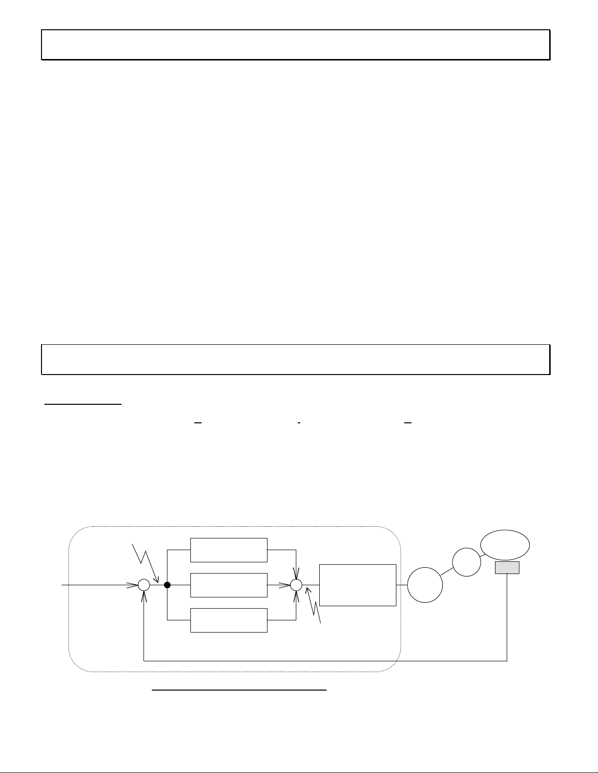
Fig. 2-1 PID Control block diagram
Target
SJ100/L100 series inverters have an integrated PID control function as standard. They can be used for
controls, such as constant flow control for fan & pump applications, and they have the following features.
l Target signal can be given not only by the digital operator but also by an external digital signal, which can
be set to 16 different targets. Furthermore, it can also be given by an analog input signal (0 - 10V or 4 20mA).
l Feedback signal can be given to SJ100/L100 by analog voltage input (10V max.)or by analog current
input (20mA max.).
l For the feedback signal, the performance area can be defined individually. For example 0 - 5V, 4 - 20mA
or others.
l Using a scale conversion function, you can get actual values of target value and/or feedback value for air
flows, water flows or temperature on the display.
Please read this guide book to use the convenient PID function of the SJ100/L100 series inverters correctly
and without any trouble.
2. PID CONTROL ON SJ100/L100
2-1 PID Control
“P” in PID stands for Proportional, “I” for Integral, and “D” for Differential. The combination of
these controls is called PID control. PID control is widely used in various fields, such as the process
control of air flow, water flow, pressure, temperature and others. It controls the output frequency of the
inverter according to PID calculation, which is based on the deviation between target and feedback. The
inverter adjusts its output frequency to correct the deviation. This control block diagram is shown in Fig. 21 below.
Target
deviation
P : Proportional
operation
I : Integral
operation
D : Differential
operation
Inverter
Frequency
command
Fan, pump, etc.
Load
Motor
Sensor &
Transducer
control
of
Feedback (Flow, Pressure or temperature etc.)
Integrated into SJ100/L100
Page 4
SJ100/L100 series inverters have integrated PID control, which is indicated by the dotted line in Fig. 2-1.
L100
Fig. 2-2 Wiring example for flow control application
4 bit of digital
Max. frequency <---
100
75
50
Output
(%)
25
1007550
25
0
Kp=2
Kp=1
Kp=0.75
Kp=0.5
Kp=0.25
0250..
≤
≤
Kp
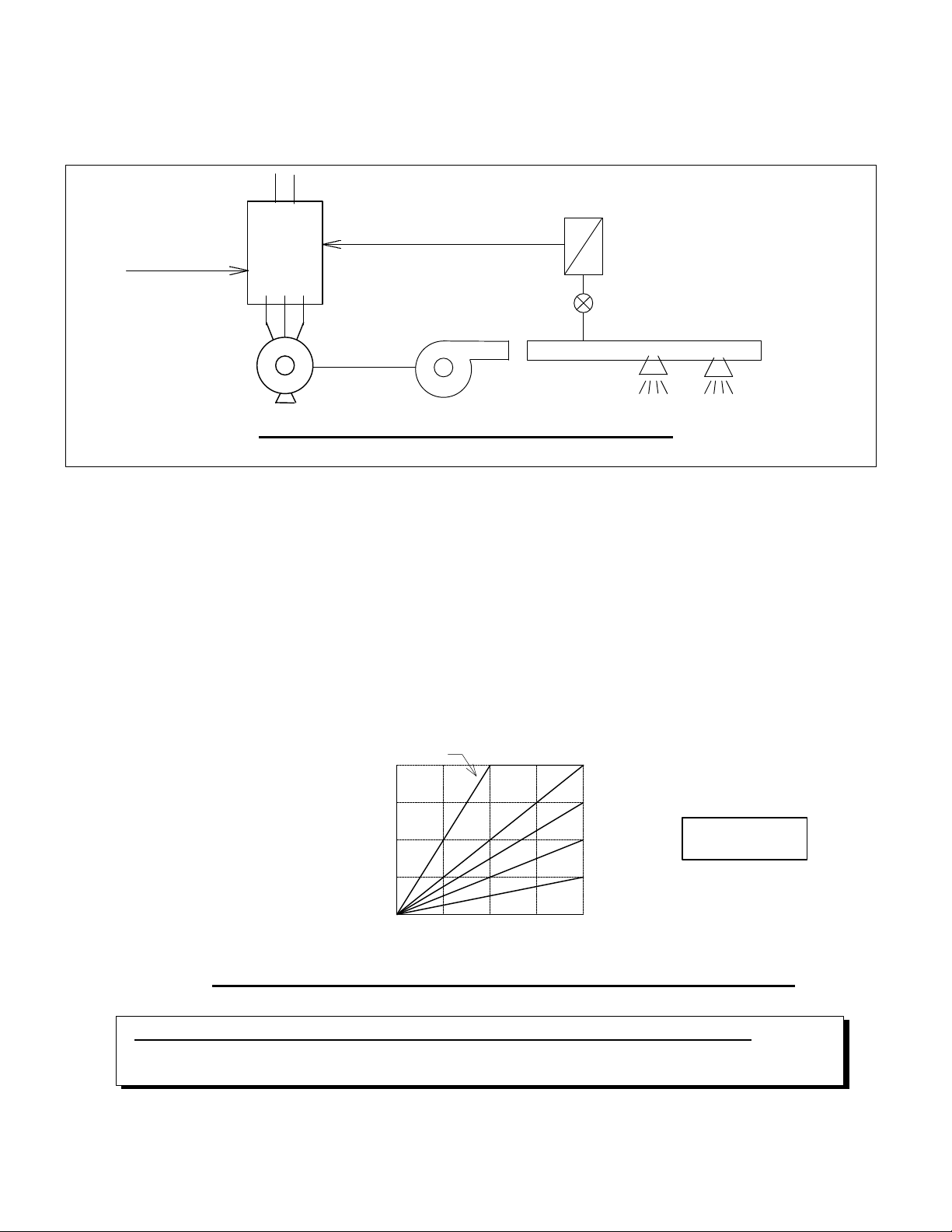
You can use PID control by setting a target value and providing a feedback signal.
The example in Fig. 2-2 shows a connection diagram for ventilation flow control in a fan application.
SJ100/
Target
input signal
Feedback
(DC0-10V, 4-20mA)
Transducer
Flow volume sensor
Fan
Motor
(1) P : Proportional Control
This controls the output frequency so that output frequency and deviation have a proportional relation.
The coefficient of deviation and output frequency (expressed in %) is called Proportional Gain (Kp). This
parameter can be set under function [A71].
Fig. 2-3 shows the relationship between deviation and output frequency. If you set a high value of Kp,
the response of the system to a rapid change in deviation is fast. However, if Kp is too high, the system
can become unstable.
frequency
Deviation(%)
Fig. 2-3 Relation between deviation and output frequency of SJ100/L100
100% of output frequency of above figure is equivalent to maximum output frequency.
Kp can be chosen between 0.2 and 5.0 in function [A71].
Page 5

(2) I: Integral Control
This is a control to correct the output frequency by integrating the deviation. In the case of
proportional adjustment, a large deviation will result in a large output frequency adjustment, but if the
deviation is small, then the resulting adjustment of output frequency will also be small. However, you
cannot make the deviation zero. Integral performance compensates this problem.
Integral correction of output frequency is performed by accumulating the deviation over time, so that
eventually, the deviation is brought to zero. Integration Gain (Ki) is a coefficient that determines how
often the deviation is to be integrated. The reciprocal of integration gain is Integration Time Constant
(Ti : Ti=1/Ki).
You must set the integration time constant (Ti) on the SJ100/L100 inverter. You can set the
time between 0.5 second and 150 seconds. When “0.0” seconds is set, NO integral control
will be performed.
(3) D : Differential Control
This is a control to correct the output frequency by differentiating the deviation. Since P control is
based on the current deviation and I control is based on the past deviation, there will always be a delay in
the control system. Differential control compensates for this problem.
Differential correction of the output frequency is performed in proportion to the rate of change of the
deviation. Therefore, D control corrects the output frequency rapidly when there is a rapid change in the
deviation. Differentiation Gain (Kd) is a coefficient to determine how often the deviation is to be
differentiated.
You can set Kd between 0 and 100. Gain is (Fmax / 10) * set value of [A74] versus change in
deviation per second.
(4) PID Control
PID control is a combined Proportional, Integral and Differential control. You can achieve the best
control by adjusting the three factors, P-gain, I-gain and D-gain. Smooth control may be achieved without
any hunting by P-control; you can correct steady-state deviation by I-control; and by D-control, you can
achieve a quick response to sudden disturbances which can influence the feedback value. A large
deviation can be suppressed by P-control. A small deviation can be corrected by I-control.
(Note) Since D-control is performed based on the differentiation of
deviation, it is a very sensitive control. Therefore, it may also
react to extraneous signals and noise, and can easily lead to
unstable system control. D-control is not normally required for the
control of processes such as flow, pressure and temperature.
Page 6

2-2 PID Gain Adjustments & Control Characteristics
NG : Divergence
Target
NG : Damped oscillation
Target
Good Control
NG : Slow response, big
The optimal gain factors of PID vary from condition to condition, and from system to system. That
means it is necessary to set those parameters by taking into account the individual control characteristics
of your particular system. The following are the characteristics that are required for a good PID control:
l Stable performance
l Quick response
l Small steady-state deviation
You adjust each parameter Kp, Ti and Kd inside the stable performance area. Generally, when you
increase each gain (Kp, Ki, Kd) parameter (= decrease Integration time : Ti), you can obtain quick
response. But if you increase them too much, the control will be unstable, because the feedback value is
continuously increasing and decreasing, which leads to an oscillation of the control. In the worst case the
system is led to a divergence mode. (Refer to Fig. 2-4)
Following are the procedures to adjust each parameter.
(1) After changing target, response is slow --- Increase P-gain (Kp)
response is quick but unstable --- Decrease P-gain (Kp)
(2) Target and feedback do not become equal --- Decrease Integration time (Ti)
become equal after unstable vibration --- Increase Integration time (Ti)
(3) Even after increasing Kp, response is still slow --- Increase D-gain (Kd)
it is still unstable --- Decrease D-gain (Kd)
Target
Controlled
object
time
Controlled
object
Controlled
object
Controlled
object
Target
steady state deviation
time
time
time
Fig. 2-4 Example of good control and bad control (in case of step response)
Page 7

3. HOW TO USE
considered to be 100%
Fig. 3-1 control block diagram of PID control
Target
Analog voltage input
Feedback
A12
A11
A14
A13
3-1 Structure & Parameters
(1) Control Mode Integrated operator A71 : 00 / 01
DOP, DRW F43 : PID SW ON / OFF
SJ100/L100 series inverters feature the following two control modes:
l Frequency control mode
l PID control mode
These can be selected by “PID function selection (A71)”.
Frequency control mode is the typical control mode of standard frequency inverters which enables
you to give a frequency command to the inverter from either the operator panel, or by analog voltage or
current, or by 4 bit digital command from the control terminals.
In the PID control mode, an output frequency is set automatically such that the deviation between
target value and feedback value approaches zero.
(2) Parameters
Fig. 3-1 shows the relation between control block diagram of PID control and each parameter. Function
numbers shown in the figure are based on the commands from the integrated operator of the inverter.
Operator
Multi stage setting
Maximum frequency is
considered to be
Pot-meter
Analog voltage input
Analog current input
10V (20mA) is
Analog current input
Voltage / current
selection is done by
A76
Reverse scale
conversion
-1
A75
100%
0
Operation area
Scale
conversion
A75
Selectable by
A01
P Gain : A72
I Gain : A73
D Gain : A74
Scale
conversion
A75
Target value display
: F01
+
+
Frequency
+
command
FB value display :
d04
Page 8

(3) Deviation Calculation
Fig. 3-2 Setting Active Range (A11=0, A12=0 or 100) : Example 1
Every calculation in PID control in the SJ100/L100 is based on “%” so that it can be used with
various applications and units of measure, such as pressure (N/m2), flow (m3/min), temperature (degrees)
and so on. For example, comparing target value and feedback value is based on % of target and % of
feedback full scale value.
However, there is a useful function called scale conversion function (A75). If you use this function,
you can set a target value and/or you can monitor target and feedback value in the actual units of the
specific application. Also, there is a “active range of PID” setting function (A11 - A14), which allows you to
define an area based on the feedback signal. Please refer to Fig.3-2 and Fig.3-3 for more detail.
(4) Target Input
Only one source for the target input can be chosen from the following:
l Keypad/Operator (Integrated operator, or DOP, or DRW)
l 4 bits of digital input from the control terminals
l Analog input terminals (O-L terminal or OI-L terminal)
In the case of digital input of the target value from the terminals, it is necessary beforehand to set the
required target values in functions A21 to A35. This allows you to define an array of target values. Then
you can select the one you require from that array according to the combination of the 4 bits of digital input
(binary). This is the same philosophy used for multi-stage speed control in the frequency control mode.
(5) Feedback Input & Setting PID Performance Area
Feedback signals should be given to one of the following units:
l Analog voltage input terminal (O terminal : 10V maximum)
l Analog current input terminal (OI terminal : 20mA maximum)
Select one of them using “Feedback input method selection [A76]”.
This feedback signal can be defined as shown in Fig.3-2 and Fig.3-3 below, so that you can achieve
suitable performance for your particular system. The “100%” shown at vertical axis is a maximum value
which is based on an internal calculation.
100
%
0
4mA0
(a) A13 = 20%
A14 = 100%
10V2V0
20mA
100%20%0
100
%
0
(b) A13 = 0%
A14 = 50%
100
%
0
10V5V0
20mA10mA0
100%50%0
(c) A13 = 25%
A14 = 75%
7.5V
15mA
75%
10V2.5V0
20mA5mA0
100%25%0
Page 9

100
Fig. 3-4 Example of Scale Conversion
(a) Factory setting
unit = [%]
(b) A75 = 0.6
unit = [m3/min]
%
25
100
75
%
100
75
%
25
0
4mA0
20%0
(a) A13 = 20%
A14 = 100%
A11 = 25%
A12 = 100%
10V2V0
20mA
100%
0
0
(b) A13 = 0%
A14 = 50%
A11 = 0%
A12 = 75%
10mA
50%0
10V5V0
20mA
100%
0
5mA0
(c) A13 = 25%
A14 = 75%
A11 = 25%
A12 = 75%
7.5V
15mA
75%
Fig. 3-3 Setting Active Range : Example 2
As you can see from Fig 3-3, if you set parameters A11 and A12 other than “0”, you should set the target
value inside the valid range of the vertical axis. Otherwise it is not possible to achieve stable performance
because there is no feedback value. That means the inverter will either output maximum frequency or
stop, or it will output lower limit frequency continuously if it is set.
(6) Scale Conversion
Using this function, you can set and display the target value and display the feedback value in the
actual units of the process variable. Set the parameters individually relative to 100% of feedback value.
With the factory default setting, the input and display value is based on 0 - 100%.
10V2.5V0
20mA
100%25%0
Example : In case of (a) in Fig.3-3, 20mA of feedback corresponds to 100% of PID internal calculation. For
instance, if actual flow at 20mA of feedback is 60 [m3/ min], you set the parameter to 0.6 (=60 /
100) in function mode A75. Then you can get the actual feedback value on the monitor mode
d04, and you can also set the target value by actual value of the control system.
Target
Monitor F01 =
0 - 100[%]
Motor
L100/
SJ100
Feedback
DC 4 -20mA
Monitor d01 =
0 - 100%
Fan
Target
Monitor F01 =
0 - 60[m3/min]
L100/
SJ100
Feedback
DC 4 -20mA
Monitor d01 =
0 - 60m3/min
Page 10

3-2 Summary of Parameters for PID Control
On the SJ100/L100 series inverters, the same function numbers are used for both frequency control
mode and PID control mode. The function name for each function is based on frequency control mode,
which is normally used for general application. Therefore, some functions have misleading explanations in
the instruction manual.
To avoid confusion, please find in below Table 3-1 the explanation of function names for frequency
control mode and PID control mode.
Table 3-1 Relation between Frequency Control Mode & PID Control Mode
Function No. Function name
Integral
Operator
DOP, DRW
Contents in case of Frequency
control mode
Contents in case of PID
control mode
Display
D04
F01
A01
Monitor mode
Monitor mode
Monitor mode
A11 F31
A12
A13
A14
A21 - A35 F11
A71 F39
A72
A73
- PID Feedback monitor
Output frequency monitor Target value monitor
Frequency command origin setting Target value origin setting
External frequency setting START
(Unit : Hz)
External frequency setting END
(unit : Hz)
External frequency setting
START rate (Unit : Hz)
External frequency setting
END rate (unit : Hz)
Multi-stage Speed 1 - 15 setting Multi-stage Target 1 - 15 setting
- PID mode selection
Feedback value input corresponding %
for lower acceptance level
(Unit : %)
Feedback value input corresponding %
for upper acceptance level
(Unit : %)
Feedback value of
lower acceptance level input
(Unit : %)
Feedback value of
upper acceptance level input
(Unit : %)
P-gain adjustment
I-gain adjustment
A74
A75
A76
D-gain adjustment
Scale conversion ratio setting
Origin of feedback signal selection
Page 11

3-3 Example of Set Up
(1) Parameter Set Up under Frequency Control Mode
Before driving the system in PID mode, you set up each required parameter under frequency control
mode. Pay particular attention to the following items.
l Acceleration ramp and Deceleration ramp
The output of the PID calculation (refer to Fig. 3-1) will not immediately be an output frequency of the
inverter. The actual output frequency of the inverter will ramp to the calculated output frequency according
to the set value of acceleration and deceleration ramps. This means that even if you set high D-gain, the
change of the actual output frequency is restricted by the set acceleration and deceleration ramp rates,
and this can lead to unstable control.
To achieve overall stable performance of the PID control, in addition to setting the three gain
parameters (A72, A73, A74), you should set the acceleration and deceleration ramps to the fastest values
the system will allow.
Be sure to re-adjust the PID parameters after you change the acceleration and/or deceleration ramps.
l Jump Frequency / Range
The required condition for setting jump frequency is that there should be no change in feedback value
when frequency is jumped. If there is a stable control point inside the jump frequency range, there will be a
hunting between both ends of the range.
(2) PID Set Up (Target & Feedback)
In PID control mode, the combination of target value and feedback signal sources can be set according to
the following table (Table 3-2).
Table 3-2 How to Set Origins for Target and Feedback
Target Input Source
Integral
Operator
Voltage input
Feedback
Source
(1) It is not possible to set both sources to the same analog input terminal.
(O-L : 0-10V)
Current input
(OI-L : 4-20mA)
A01 = 02
A76 = 01
A01 = 02
A76 = 00
Multi-stage
target (Terminal)
Integral
Potentiometer
A01 = 00
A76 = 01
A01 = 00
A76 = 00
Analog Voltage
input (O-L)
-
A01 = 01
A76 = 00
Analog Current
input (OI-L)
A01 = 01
A76 = 01
-
(2) The inverter will decelerate to a stop according to the set deceleration ramp rate when a stop command is
received while in PID control mode.
Page 12

(3) Scale Conversion Factor Setting
Set this factor according to your application, e.g. flow, pressure, temperature and so on. For a detailed
explanation, please refer to item (6) on page 9.
(4) Target Input by Digital Input Signal
Please refer to the following when changing the target with the digital input signal (4 bit max.).
(a) Input terminal assignment
L100 series inverters have five intelligent input terminals. The SJ100 series have six. Assign “CF1”,
“CF2”, “CF3” and “CF4” to 4 of the intelligent input terminals. This assignment is done with function
numbers C01 to C05 (or C06 for SJ100), which correspond to terminals 1 to 5 (or 6) on the I/O
terminal.
(b) Setting each target value
Next, set the required number of targets (up to 16 targets maximum) according to the following table
(Table 3-3). Set them using functions A21 to A35 which correspond to target 0 to 15. A20 and F01
correspond to a target 0. Please note that in case a scale conversion ratio is set, you should set those
targets as converted value according to this ratio.
Table 3-3 Multi-stage Target Input (1 : ON, 0 : OFF)
No. CF4 CF3 CF2 CF1 Referred Target number (Function number to be inputted)
1 0 0 0 0
2 0 0 0 1
3 0 0 1 0
4 0 0 1 1
5 0 1 0 0
6 0 1 0 1
7 0 1 1 0
8 0 1 1 1
9 1 0 0 0
10 1 0 0 1
11 1 0 1 0
12 1 0 1 1
13 1 1 0 0
14 1 1 0 1
15 1 1 1 0
16 1 1 1 1
Target 0 (A20 or F01)
Target 1 (A21)
Target 2 (A22)
Target 3 (A23)
Target 4 (A24)
Target 5 (A25)
Target 6 (A26)
Target 7 (A27)
Target 8 (A28)
Target 9 (A29)
Target 10 (A30)
Target 11 (A31)
Target 12 (A32)
Target 13 (A33)
Target 14 (A34)
Target 15 (A35)
Note: If you need only 4 targets, you would only use CF1 and CF2.
(5) PID Mode Selection
Set PID mode selection A71 to “01”. You can also set this function first.
Page 13

3-4 Example of Each Gain Adjustment (Kp & Ti)
l Check the response of feedback signal or the output frequency of the inverter when making a step
change in the target. (Please refer to Fig. 2-4)
l Use an oscilloscope or other measuring equipment to observe the waveform of the feedback value or
output frequency of the inverter (frequency monitor).
l Prepare two targets that can be changed by digital input signal in advance, so that you can change
targets with a step change.
l Before proceeding, the control system must be stable.
(1) Adjustment of Proportional Gain (Kp : Function No. A72)
Start driving only with P-control, without I-control and D-control (i.e., set them to ZERO).
First, set a minimal value of P-gain and see how it works. According to the result, increase Pgain gradually. Repeat this procedure until you get good performance. (Alternatively, you set
maximum P-gain and observe the performance. If the system is not stable, you set a medium value
and see how it works. Repeat this procedure...)
If the performance is unstable, decrease P-gain.
If the steady state deviation is in the acceptable range, you have completed tuning the P-gain.
(2) Adjustment of Integration Time (Ti : Function No. A73) & Readjustment of K
p
Start adjustment by setting minimum integration time. If it is difficult to adjust, try decreasing
the P-gain.
In case the deviation does not converge, decrease integration time. If the control becomes
unstable at that time, decrease P-gain.
Repeat this procedure to find the suitable parameters.
(Note) In the instruction manual, the description of A73 function is “Integration Gain (Ki)”. But
actually this is an “Integration Time (Ti)”, which is the inverse of gain. Please be aware of
this while you set this parameter.
3-5 General Cautions
(1) When you set AVR function (A81) to “DOFF” (which makes the AVR function invalid while
decelerating) with PID control, there is a possibility the motor may exhibit hunting in some
applications. This is because the motor repeatedly accelerates and decelerates each time the AVR
function operates. This may lead to unstable rotation of the motor.
Solution: Set AVR function ALWAYS OFF in this case.
Page 14

4. EXAMPLE OF ACTUAL APPLICATION
Fig. 4-1 Example of Constant Flow Control
You can find in this chapter some typical setting examples for actual applications.
4-1 Constant Flow Control
L100/
SJ100
Target
4 bit digital signal
Feedback
4 - 20mA
(500m3/min when 20mA)
Transducer
Flow sensor
Motor
In this case (targets are 150m3/min &
300m3/min), the settings would be as follows:
Function Number
Integrated Operator
F01
DOP, DRW Under PID Control Mode
Monitor
Target 0
mode
A01
A11 F31
A12
A13
A14
A21 F11
A71 F39
A72
A73
A74
A75
A76
Target input origin setting
Feedback value input corresponding %
for lower acceptable level
Feedback value input corresponding %
for upper acceptable level
Feedback value input
for lower acceptable level setting
Feedback value input
for upper acceptable level setting
Target 1
PID mode selection
P-gain adjustment
I -gain adjustment
D-gain adjustment
PID scale conversion factor setting
Source of feedback signal selection
Pump
Function Name
500m3/min 100
300m3/min
150m3/min
60
30
Input
Data
150
02
0
100
20
100
300
01
-
-
-
5.0
00
Flow : 150m3/min or 300m3/min constant
%
0
4mA0
5.8mA
20%0
29%
10.6mA
53%
Feedback value range setting
Remarks
Directly input “150 [m3/min]”
because scale conversion ratio is
given
Operator
0%
100%
20%
100%
300 [m3/min]
PID mode ON
Depends on each application
100% when 500 [m3/min]
Feedback from OI-L terminal
20mA
100%
Page 15

4-2 Constant Temperature Control
Fig. 4-2 Example of
Target
In the case of constant flow control shown in the previous section, output frequency of the inverter
increases if the feedback value is smaller than target value, and output frequency of the inverter
decreases if the feedback value is bigger than the target value. However, in the case of constant
temperature control, this is the opposite. The inverter increases its output frequency to drive a cooling fan
much faster when the temperature feedback signal is higher than target temperature, for example. Below
you can find an example of how to configure such an application.
L100/
SJ100
Feedback
Multi-stage Target
0 - 10V
(50 degrees at 10V)
Motor
Constant Temperature Control
In this case (targets are 20 & 30 degrees), the
settings would be as follows:
Fan
Transducer
50deg. 100
%
30deg.
20deg.
60
40
Temperature
:Either 20 or 30 degrees constant
Temperature sensor
0
4V
0
40%
6V
60%
Feedback value range setting
10V0
100%
Function Number
Integrated Operator
F01
A01
A11 F31
A12
A13
A14
A21 F11
A71 F39
A72
A73
A74
A75
A76
Function Name
DOP, DRW Under PID Control Mode
Monitor
Target 0 20 Directly input “20 [deg]” because
mode
Target input origin setting 02 Operator
Feedback value input corresponding %
for lower acceptance level
Feedback value input corresponding %
for upper acceptance level
Feedback value input
for lower acceptance level setting
Feedback value input
for upper acceptance level setting
Target 1 30 30 deg
PID mode selection 01 PID Mode ON
P-gain adjustment - Depends on each application
I -gain adjustment D-gain adjustment PID scale conversion ratio setting 0.5 100% when 50 [deg]
Origin of feedback signal selection 01 Feedback from OI-L terminal
Input
Data
scale conversion ratio is given
100 100%
0 0%
0 0%
100 100%
Remarks
Page 16

5. INDEX
- A - - R -
acceleration ramp 11 response 6
AVR function 13
- S -
- C - scale conversion 9
control mode 7, 10 steady state deviation 6
- D - - T -
damped oscillation 6 target 8
deceleration ramp 11 target input 12
deviation 3, 8 target origin input 11
differential control 5
differential gain (Kd : D-gain) 5
divergence 8
- F -
feedback 8
feedback origin input 11
frequency control mode 7
- G -
gain adjustment 6, 13
- I -
integral control 5
integration gain (Ki : I-gain) 5, 13
integration time (Ti) 5, 13
11
- J - 12
jump frequency / width
- M -
multi-stage target
- P -
PID control 3
PID control mode 7
PID performance area 8
proportional control 4
proportional gain (Kp :P-gain) 4, 13
 Loading...