

Page 1

SERVICE MANUAL
MANUEL D'ENTRETIEN
WARTUNGSHANDBUCH
CAUTION:
Before servicing this chassis, it is important that the service technician read the “Safety
Precautions” and “Product Safety Notices” in this service manual.
No. 0253
L22DP03C
L22DP03U
D a t a c o n t a i n e d w i t h i n t h i s S e r v i c e
manual is subject to alteration for
improvement.
ATTENTION:
Avant d’effectuer l’entretien du châssis, le technicien doit lire les «Précautions de sécurité»
et les «Notices de sécurité du produit» présentés dans le présent manuel.
VORSICHT:
Vor Öffnen des Gehäuses hat der Service-Ingenieur die „Sicherheitshinweise“ und „Hinweise
zur Produktsicherheit“ in diesem Wartungshandbuch zu lesen.
FOR ALL PARTS PLEASE MAKE
CONTACT WITH ASWO.
FOR YOUR LOCAL OUTLET GO TO
Les données fournies dans le présent
manuel d’entretien peuvent faire l’objet
de modifications en vue de perfectionner
le produit.
D i e i n d i e s e m Wa r t u n g s h a n d b u c h
enthaltenen Spezifikationen können sich
zwecks Verbesserungen ändern.
www.aswo.com
SPECIFICATIONSANDPARTSARESUBJECTTOCHANGEFORIMPROVEMENT
Colour Television
May 2009
Page 2

TABLE OF CONTENTS
1 INTRODUCTION.........................................................................................................................................3
2 GENERAL DESCRIPTION ........................................................................................................................3
3 POWER STAGE................. ..........................................................................................................................4
4 MICROCONTROLLER PORT CONFIGURATION...............................................................................4
5 SIDE BOARDS AND CONNECTORS .......................................................................................................5
5.1 Keypad ......................................................................................................................................... 5
5.2 Infrared & LED ........................................................................................................................... 6
5.3 DVB-T ......................................................................................................................................... 6
5.4 DVD .............................................................................................................................................8
5.5 LVDS .......................................................................................................................................... 9
5.6 IPS POWER CARD.....................................................................................................................9
6 IC SPECIFICATIONS ...............................................................................................................................10
6.1 Microcontoller/Video&Audio Processor (VCT4953G) ............................................................10
6.2 Scaler/De-interlacer (MST-TSUMU38BF) ................................................................................13
6.3 Audio Stage (LM358D,MP7721)................................................................................................. 16
6.4 HeadPhone Amplifier (TDA1308T) ...........................................................................................16
6.5 Audio Matrix Switch (TEA6422D) ............................................................................................ 19
6.6 HDMI Receiver (ANX9021) ....................................................................................................... 19
6.7 Video Switch (PI5V512) .............................................................................................................. 20
6.8 Tuner (DTT71306) ...................................................................................................................... 21
6.9 SAW Filter (X6966M) ............................................................................................................... 22
6.10 I2C Switch (74HCT4053) ..........................................................................................................22
6.11 Audio DAC (CS4334) ............................................................................................................... 23
6.12 IC E
6.13 SPDIF Switch (NLAST4599) .....................................................................................................24
6.14 17MB29 Block Diagram.............................................................................................................26
EPROM 24LC02 2Kbx8 .................................................................................................... 24
Page 3

1 INTRODUCTION
The purpose of this document is to define the operation of 17MB29 chassis, capable of driving 22”
TFT LCD panel. It is aimed to provide information to engineering staff to understand the operation and specs
of the TV. The other related technical documents are given in Table1:
Title
1 17MB29 schematics
2 IR receiver and LED display board schematics
3 Keypad board schematics
4 DVD module card schematics
5 DVB-T module card schematics
Table1.1: Related documents
2 GENERAL DESCRIPTION
The system is a low to mid end; 22” 1680 x 1050 TFT TV solution basically for EU market with
VCT4913G microcontroller / video audio processor chip on a 2-layer PCB. Since the target market is EU, the
first release of the TV will support PAL/SECAM B/G/D/K/I/L/L’.
TFT-LCD panels.
DVB-T.
• 1xTuner (both analog and DVB-T)
• 1xDVD
• 1xScart
• 1xPC (VGA)
• 2xHDMI (optional)
• 1xBack AV (optional)
• 1xSIDE YPBPR (optional)
• Speaker (stereo, 2x4 Ω, 2x4Watt)
• Headphone (stereo) (optional)
• Audio line out (stereo and mono) (optional)
• DVD/DVB-T coaxial SPDIF out(optional)
A DVD loader is used to read DVD content and a DVB-T module card is used to support
Inputs
Outputs
The target panel is 22” W 1680 x 1050
1
Page 4

General default features
• Multi System Reception: PAL-SECAM BG-DK-I/I’-L/L’
• Menu system (multi language)
• 100 program storage locations
• OSD (on-screen display)
• Teletext
• IR Control (RC5 and other customer specific protocols)
• “No Ident” Timer
• Child Lock
• Sleep Timer
• WSS (16:9/4:3 Aspect Ratio Auto Switch)
Sound Features
• Equalizer
• FM Radio
• Linear Stereo
• German-NICAM Stereo
• 5-Band Equalizer Control
• SRS TRU Surround (OPT)
• SRS TRU Bass (OPT)
• BBE, WOW (OPT)
Picture Features
• WIDE PANEL---4:3,16:9, Auto(opt), Subtitle(opt), Zoom(opt), Panoramic(opt)
• Picture Modes ( Bright, Standard, Soft)
• Media Window Enhancement (MWE)
• Backlight brightness setting (movie/normal/bright)
• Multi System Reception : PAL-SECAM BG-DK-I/I’-L/L’
• NTSC Video Playback
• WSS (16:9 / 4:3 Aspect Ratio Auto Switch)
• Channel Type Sorting (Favorite/Sport/Music/News/Movie)
Tuning Options
• FST
• Frequency Search (Optional)
• APS (Auto Search/Name/Sort)
• Auto Search
• CATV/HYPERBAND
Keyboard
• Volume -/ +Button
• Program -/+ Button
• Menu Button
• TV / AV Button
2
Page 5

Teletext/OSD
• Simple Text 10 Pages
• Fastext & Top Text (OPT)
• Teletext Languages (ALL)
• Character Based OSD
Electrical features
•IPS generates 12V and 5V DC supply.
•<1W standby power consumption
System Building Blocks
17MB29 chassis main blocks are as follows:
•Analog Front End : VCTI (Microcontroller+Video Proccessor+Audio Proccessor+IF
Demodulator+ Teletext Decoder+ OSD Generator)
•Back End : MST-TSUMU38BF(Scaler, Deinterlacer, OSD Generator)
Analog Front End
17MB29 main board consists of two major blocks. The first block is analog front-end and this
block is handled by VCTI chip that is highly multifunctional. VCTI performs Tuner IF demodulation,
CVBS, RGB, SVHS and audio input selection and processing. The audio processor (MSP) supports
equalizer, tone control, volume control, AVL, surround effect etc. The video processor (VSP) handles
video processing such as color standard detection and demodulation, picture alignment (brightness,
contrast, color etc.). The IC also has a teletext decoder with fastext memory. The processed video output
is sent to MST-TSUMU38BF, scaler/deinterlacer in RGB format together with a composite sync.
The TV tuner is PLL controlled symmetrical IF output type. The IF signal is filtered by a single
SAW filter. Inter-carrier sound demodulation is performed by the system. After the SAW filter block, IF
signal is processed by VCTI IF demodulator. Audio signal is digitally filtered in the IF demodulator
block. The same IF signal is buffered and sent to DVB-T module card, tdm1300.Since VCTI can handle
all the audio processing, there is no need for additional audio processor solution on the board.
MSP has two audio inputs which are assigned to the Scart in L/R and Audio Switch L/R output.
MSP has three audio outputs which are assigned to the headphone amplifier L/R input, audio amplifier
L/R input and Audio switch L/R input. The board employs MP7721 and TDA1308 to drive speaker and
headphone outputs, respectively. Switching control for other audio inputs and outputs (HDMI, Back AV,
PC, DVD, and DVB-T) is achieved by an I2C controlled audio switch (TEA6422).
3
Page 6
Back End
MST-TSUMU38BF has two ADC inputs. First ADC input is assigned to the VCTI RGB output.
Other RGB/YPbPr inputs are multiplexed for the second ADC input. HDMI receiver ANX9021 analog
output, VGA RGB input and the synchronization signals are multiplexed by a primary RGB switch
(PI5V512). MST-TSUMU38BF has an embedded LVDS transmitter. There are three PWM output ports.
PWM0 is assigned to analog/digital dimming control for the backlight, PWM1 is used for backlight
on/off and panel logic power supply on/off control and PWM2 is used to control PC/HDMI switch IC
(PI5V512).
3 POWER STAGE
The DC voltages required at various parts of the chassis and inverters are provided by a main power
supply unit and power interface board. IPS generates 12V and 5V DC supply. Power stage which is
on-chasis generates +12V for audio amplifier and 5V stand by voltage and 33V, 12V, 5V, 3.3V and 1.8V
supplies for other different parts of the chassis.
4 MICROCONTROLLER PORT CONFIGURATION
PIN
NO
47 P10 MST_RESET O Scaler reset
PROTECT I Short circuit detection
48 P11 TV_RXD I IDTV UART receive signal
49 P12 TV_TXD O IDTV UART transmit signal
50 P13 IRQ O IDTV interrupt request signal
51 P14 KEY I Keyboard function select
52 P15 SC_PIN8 I Scart function select
53 P16 DVD_IR_ON/OFF O DVD infrared signal on/off control
54 P17 POWCON O Standby on/off control
PORT
NAME
SIGNAL NAME TYPE FUNCTION
4
Page 7
PIN
NO
55 P20 HDMI_HP_INV O HDMI hot plug signal
56 P21 CS O Switching control for Mstar bus and system I2C
62 Safety VCTI_HS O VCTI composite sync output
78 FBIN DVD_SENSE I DVD module detection
85 Vert+ TV/DVB_SW O IDTV/TV I2C and AGC switch control for tuner
27 P22 WP O Write protection control for NVM
28 P23 IR I Infrared input
PORT
NAME
SIGNAL NAME TYPE FUNCTION
Table 4.1 VCTI port configuration
5 SIDE BOARDS & CONNECTORS
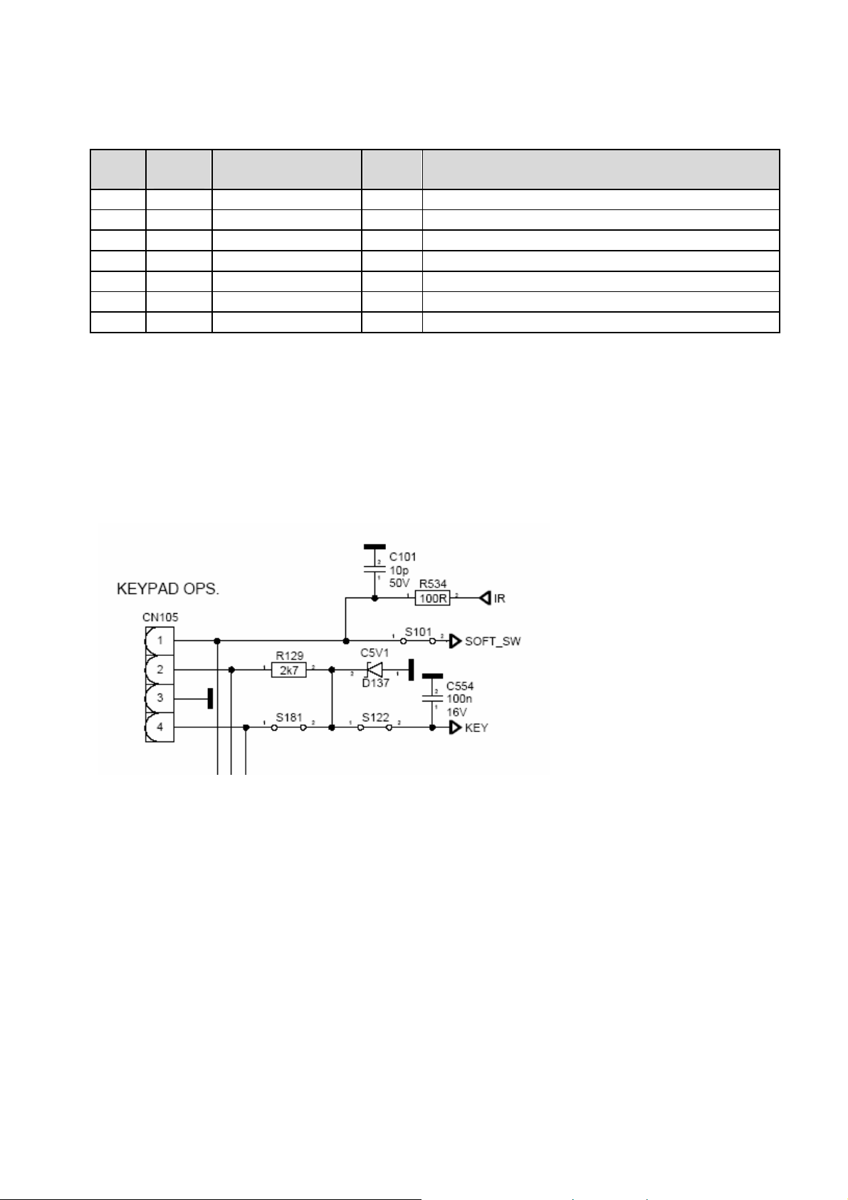
5.1 Keyboard
A four-pin connector is used between 17mb29 and the keyboard:
KEY signal is sent directly to microcontroller ADC port and depending on the voltage level of
KEY signal, microcontroller performs one of these actions: menu, program+, program-, volume+,
volume- and source.
SOFT_SW signal is used to switch between “power-off” and “standby” modes.
5
Page 8
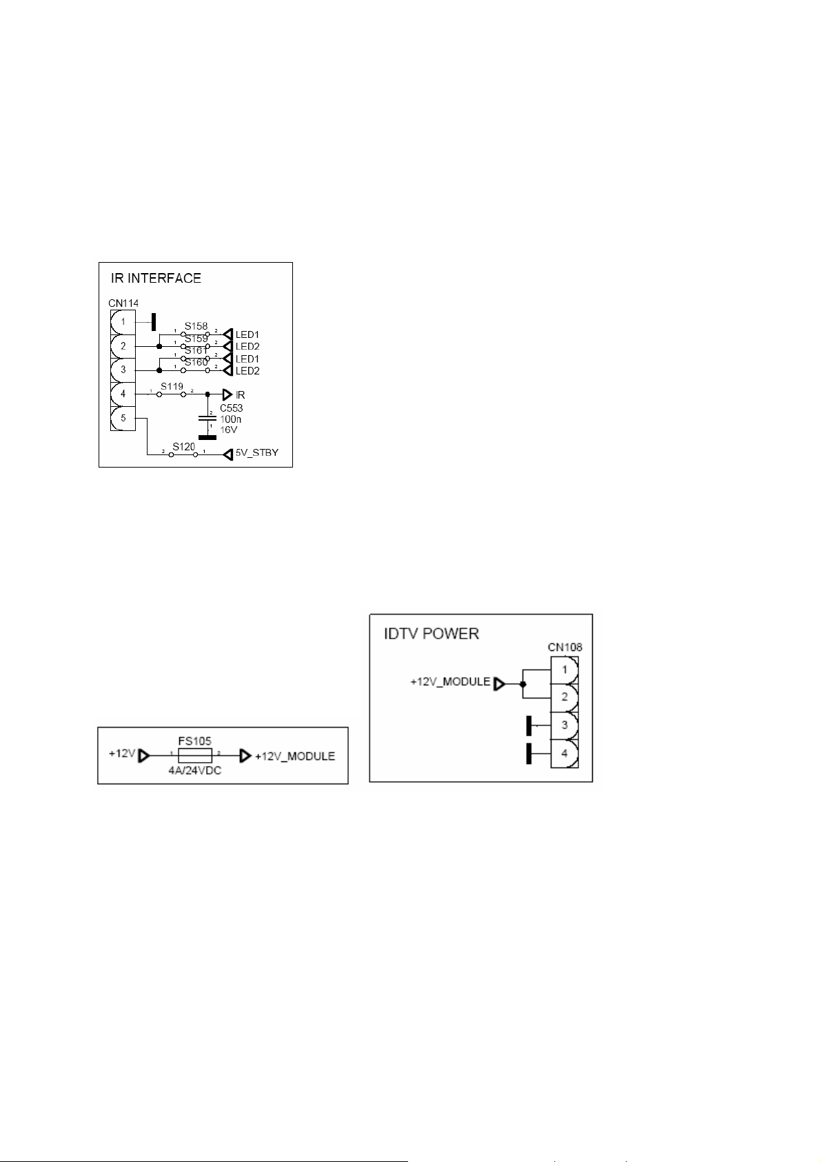
5.2 Infra-red & LED
A five-pin connector is used between 17MB29 and the LED board: Pin2 and pin3 carry the control
signals for the LED. Pin4 carries the infra-red signal to the microcontroller. Pin5 is used to power up the
LED board.
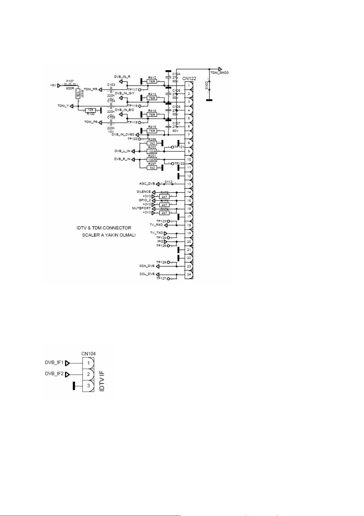
5.3 DVB-T module board
DVB-T module board (
cables are used to connect 17MB29 and
12V (500mA) is sent to
Analog RGB(YPbPr), CVBS, stereo audio, tuner control (SCL, SDA, AGC), and three GPIO port
outputs of
TDM1300, together with UART ports (TV_RXD, TV_TXD, IRQ) are carried by data cable.
TDM1300 by power cable:
TDM1300) is used to receive digital terrestrial broadcast signals. Three
TDM1300: power, data and IF.
6
Page 9
DM1300 board has no tuner on it. Instead, the tuner of 17MB29 is used for both analogue and
T
digital reception. Tuner is controlled by either the 17MB29 microcontroller (VCTI), or
microcontroller. The IF (intermediate frequency) output of the tuner is sent to TDM1300 board for digital
reception.
TDM1300 board
7
Page 10
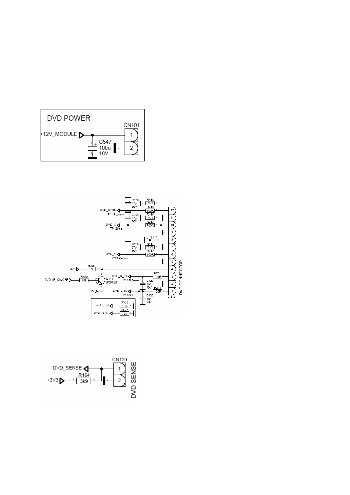
5.4 DVD module board
DVD module board has two parts: a loader and an electronic card. Electronic card controls the
loader and has connections with 17MB29 and DVD keypad.
Three cables are used to connect 17MB29 and DVD electronic card: power, da
12V (500mA) is sent to DVD electronic card by power cable:
Y/C and/or CVBS video, stereo audio outputs and infra-red input of DVD module board is carried on
data cable:
ta and sense.
When a DVD is inserted into the loader, the DVD electronic card sends an interrupt signal
(DVD_SENSE) to the 17MB29 microcontroller:
8
Page 11
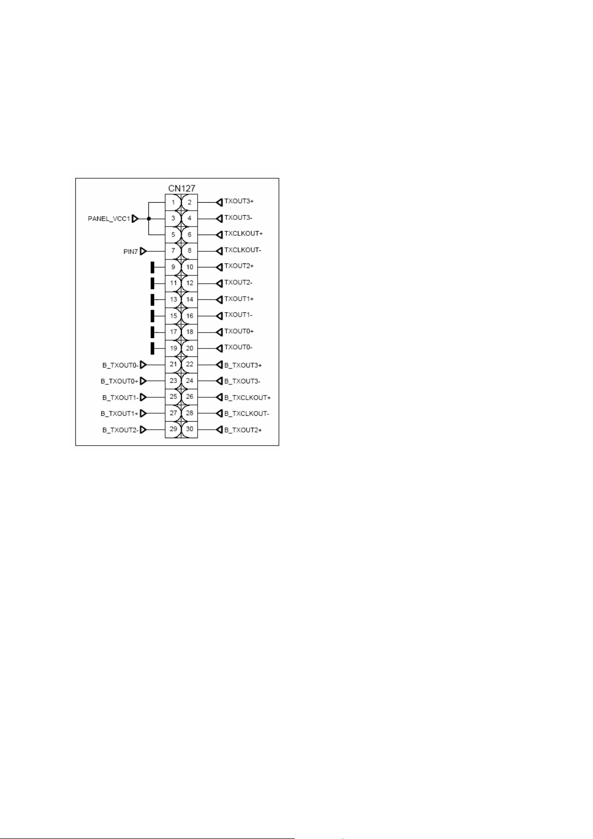
5.5 LVDS connector
MST-TSUMU38BF is used for dual LVDS output on 17MB29:
Panel_Vcc1 is the power input for the panel LCD module. PIN7 signal is a logic 1 or 0 signal
depending on the panel type.
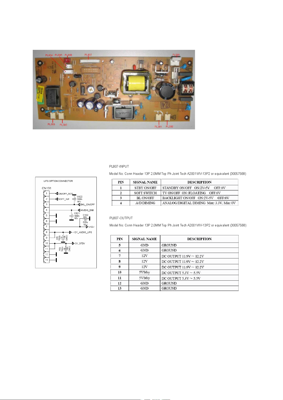
5.6 IPS Power Card
This product include AC-DC fl
converter. There are two option wh
PFC
(Power Factor Correction) coil.
yback converter, DC-DC converter and DC-AC half bridge
ose total output power are 52W and 55W. This system does not have
9
Page 12
10
Page 13

6 IC SPECIFICATIONS
6.1 Microcontroller/Video&Audio Processor (VCT4913G)
VCTI49xy is composed of microcontroller, video proccessor, display and deflection processor,
sound proccessor and IF blocks as shown in
figure below.
11
Page 14

VCTI49xyl family has two package types; PSSDIP88 and PMQFP144. PSSDIP88 package
is chosen because of its convenience in the soldering process. PSSDIP88 package has two versions;
1 and 2. PSSDIP88-2 package is the “pinning mirrorred” version of PSSDIP88-1 and is preferred
to be used for layout compatibility.
12
Page 15

13
Page 16

6.2 Scaler/De-interlacer (MST-TSUMU38BF)
The TSUMU38BF is total solution graphics processing ICs for LCD displays with panel
resolutions up to XGA and WXGA+ / SXGA+ respectively. They are configured with a high-speed
integrated triple-ADC/PLL, a high quality display processing engine, and an integrated multi-purpose
output display interface that can support all major panel interface formats. To further reduce system costs,
the MST517A-M also integrates intelligent power management control capability for green-mode
requirements and spread spectrum support for EMI management.
The TSUMU38BF also incorporates a new Dynamic Frame Rate(DFR) generator for the digital
output video to the display panel that preserves the advantages of a fixed output clock rate , while
eliminating the output end of frame short-line.
MST has a built-in OSD generator with 291 character font programmable RAM. OSD generator
supports 2/4/8 multi-color fonts, 8/16/256 color palette and 1K code attributes.
Supports up to 8-bit LVDS UXGA/WSXGA+(1680*1200 / 1680*1050 ) panel interface .
14
Page 17

PIN
NO
PORT
NAME
SIGNAL
NAME
TYPE FUNCTION
4 PWM0 AN/DIG_DIM O Analog or digital dimming control
55 PWM1 BKL_ON/OFF O Backlight On/Off Control
PVCC_ON/OFF O Panel Logic Power On/Off control
196 PWM2 PC/HDMI_SW O Video switching control
Table 6.2.1: MST5x7A-M port allocation
15
Page 18

6.3 Audio Stage
Audio Preamplifier(LM358D)
These circuits consist of two independent, high gain, internally frequency compensated which were
designed specifically to operate from a single power supply over a wide range of voltages. The low
power supply drain is independent of the magnitude of the power supply voltage.
Audio Amplifier (MP7721)
The MP7721 is a stereo 2 x 10W Class D Audio Amplifier. It is one of MPS’ second generation
fully integrated audio amplifiers which dramatically reduces solution size by integrating the following:
• 250mΩ power MOSFETs Startup
• Shutdown pop elimination
• Short circuit protection
• Mute / Standby
The MP7721 utilizes a single ended output structure capable of delivering 2 x 10W into 8Ω
speakers. MPS Class D Audio Amplifiers exhibit the high fidelity of a Class A/B amplifier at efficiencies
greater than 90%. The circuit is based on the MPS’ proprietary variable frequency topology that delivers
low distortion, fast response time and operates on a single power supply.
16
Page 19

17
Page 20

6.4 Headphone Amplifier (TDA1308T)
TDA1308T is an integrated class AB stereo headphone driver contained in an SO8, DIP8, or a
TSSOP8 plastic package. SO8 package is used in 17MB29. The device is fabricated in a 1mm CMOS
process. The main features of this IC are:
• Wide temperature range
• No switch ON/OFF clicks
• Power supply ripple rejection
• Low power consumption
• Short-circuit resistance
• High performance
– high signal-to-noise ratio
– high slew rate
– low distortion
• Large output voltage swing
6.5 Audio Matrix Switch (TEA6422D)
TEA6422D is a bus-controlled audio matrix switch in an SO28 plastic monopackage. The main
features of TEA6422 D are:
• 6 stereo inputs
• 3 stereo outputs
• Gain control
• Cascadable (2 different addresses)
• Serial bus controlled
• Low noise
• Low distortion
• ESD protection
• Wide dynamic range (3 Vrms)
18
Page 21

6.6 HDMI Receiver (ANX9021)
The ANX9021 is an advanced multimedia receiver compliant with High Definition Multimedia
Interface (HDMI) Specification 1.2. HDMI is the first transport standard to unify digital video, audio,
and control da ta over lowcost cables. It connects digital television, flat panel displays and project
systems digitally to multimedia sources: DVD players, high definition settop boxes, digital video tape
recorders, and personal computers.Digital transmission, in turn, delivers an uncompromising multimedia
experience.
HDMI also i ncludes encryption for premium contents pursuant to the HighBandwidth Digital
Content Protection (HDC P) standard. The ANX9021 embeds the HDCP keys and key selection vectors
to reduce manufacturing co mplexity and system cost.
The ANX9021 receives two HDMI data streams and decodes the selected input into digital audio
and vide
o data outputs. The receiver incorporates Analogix’s proprietary WideEye™ architecture, which has
receiv ed considerable industry acclaim when introduced in Analogix’s 6.25 Gbps SerDes products for
telecom a nd datacom applications. Applying the same advanced techniques in ANX9021 allows
displays systems to achieve errorfree HDMI reception over long, inexpensive cables up to 20 meters and
assure the widest ran ge of interoperability against uncertain qualities of cheap cables from lowcost
suppliers as the standard ma tures.
The ANX9021 can receive and output up to eight digital audio channels at up to 192 kHz sampling
rate, m aking it the leading component for integrated home theaters and high definition televisions. The
device sup ports direct connections to a wide selection of audio DACs and decoders through industry
standard I2S or S/PDIF interfaces. The ANX9021 is offered in 144-lead TQFP lead-free packages.
The main features of ANX9021 are:
• Dual-channel HDMI receiver supporting link data rate up to 1.65 Gbps
• HDMI 1.2, HDCP 1.1 and DVI 1.0 compliant
• WideEye™ architecture for signal conditioning and equalization
osupport cable length up to 20m
obetter than 10E-12 bit error rate
• Digital interface to video processor supporting
o24-bit RGB / YCbCr 4:4:4
o16/20/24 bit YCbCr 4:2:2
o8/10/12 bit YCbCr 4:2:2 (ITU BT-656)
o12-bit double data rate interface
• Color space conversion: RGB to/from YCbCr both directions (601 and 709 standards)
• Auto video mode configuration
19
Page 22

• Analog RGB/YPbPr output with 8-bit linearity
• Digital audio interface
o32 to 192 kHz audio sampling rate
oUp to 4 I2S interface for 8-channel audio
oS/PDIF interface supporting PCM, Dolby Digital™, DTS™ digital audio transmission
using IEC 60958 and IEC 61937
oConfigurable soft mute
• Integrated HDCP decryption engine and pre-programmed keys
• Programmable power management with automatic shutdown for power conservation
• Supports automated link integrity checking
• 144-lead TQFP package supporting lead-free and green requirements
6.7 Video Switch (PI5V512)
PI5V512 is a wide-bandwidth 5-port 2:1 mux/demux video switch with High-Z outputs. The main
features of PI5V512 are:
• High-performance, low-cost solution to switch between video sources
• Wide bandwidth: 550 MHz
20
Page 23

• Low On-Resistance: 5Ω
• Low crosstalk at 10 MHz: –90dB
• Ultra-low quiescent power (0.1µA typical)
• Single supply operation: +5.0V
• Fast switching: 10ns
• Packaging (Pb-free & Green available): 24-pin 150-mil wide plastic QSOP (Q)
6.8 Tuner (DTT71306)
DTT713xx is a digital terrestrial tuner designed for reception in VHF I, VHF III and UHF,
compliant with the European digital terrestrial standard ETS 300744 and CENELEC standards EN 55013
and EN 55020. It covers all channels from 44.25 MHz to 863.25 MHz
The main features of DTT713xx are:
• Integrated tuner for digital and anlog broadcasting
• Low phase noise, high sensitivity performance
• Small size: 50mm x 35mm x 12mm
• Internal wide band AGC
• 3V3 and 5V I2C bus programmable
21
Page 24

• General-purpose port output
• Antenna power supply input
6.9 SAW Filter (X6966M)
6.10 I2C Switch (74HCT4053)
74HCT4053 is a triple 2-channel analog mux/demux with a common enable input. Each
multiplexer/demultiplexer has two independent inputs/outputs (nY0 and nY1), a common input/output
(nZ) and three digital select inputs (S1 to S3).
22
Page 25

6.11 Audio DAC (CS4334)
CS4334 is a 8-pin, 24-bit, 9
Delta-Sigma modulation, where the modulator output controls the reference voltage input to an
ultra-linear analog lowpass filter. This architecture allows for infinite adjustment of sample rate between
2 kHz and 100 kHz simply by changing the master clock frequency.
The main features of CS4334 are:
• Complete stereo DAC system: interpolation, D/A, output analog filtering
• 24-bit conversion
dB dynamic range
• 96
• -88dB THD+N
• Low clock jitter sensitivity
• Single +5V power supply
• Filtered line level outputs
• On-chip digital de-emphasis
• Popguard
6KHz stereo D/A converter. The CS4334 family is based on
23
Page 26

6.12 IC EEPROM 2Kbx8(24LC02)
The 24LC01/02 is a 1K/2K-bit serial read/write non-volatile memory device using the CMOS
floating gate process.Its 1024/2048 bits of memory are organized into 128/256 words and each word is 8
bits. The device is optimized for use in many industrial and commercial applications where low power
and low voltage operation are essential. Up to eight 24LC01/02 devices may be connected to the same
two-wire bus.
6.13 SPDIF Switch (NLAST4599)
The NLAST4599 is an advanced high speed CMOS single pole − double throw analog switch
fabricated with silicon gate CMOS technology. It achieves high speed propagation delays and low ON
resistances while maintaining low power dissipation. This switch controls analog and digital voltages
that may vary across the full power−supply range (from VCC to GND).
The device has been designed so the ON resistance (RON) is much lower and more linear over
input voltage than RON of typical CMOS analog switches.
The channel select input structure provides protection when voltages between
applied, regardless of the supply voltage. This input structure helps prevent device destruction caused by
supply voltage − input/output voltage mismatch, battery backup, hot insertion, etc.
Main features of NLAST4599 are:
• Select Pin Compatible with TTL Levels
• Channel Select Input Over−Voltage Tolerant to 5.5V
• Fast Switching and Propagation Speeds
• Break−Before−Make Circuitry
• Low Power Dissipation: ICC
• Diode Protection Provided on Channel Select Input
• Improved Linearity and Lower ON Resistance over Input Voltage
• Latch−up Performance Exceeds 300
= 2A (Max) at TA = 25°C
mA
0V and 5.5V are
24
Page 27

• ESD Performance: HBM > 2000
• Chip Complexity: 38 FETs
V; MM > 200V
25
Page 28

26
Page 29

Page 30

BACKAV/SIDEVEYPBPR
2
SIDE_PR1
JK102
JK105
JK109
JK103
JK106
3
1
2
3
1
2
3
1
2
3
1
2
3
1
VCTI_PROG_EN
SIDE_PB1
F133
1 2
600R
F135
1 2
600R
F136
1 2
600R
R103
1 2
2
1
2
1
1 2
R505
1 2
10k
PCCONNECTOR
15
PC_SCL
14
13
12
11
10
9
8
7
6
5
4
3
2
1
CN111
PC_SDA
VGA_5V
2
1
2
D125
D126
3
BAV99
1
C106
12p
50V
2k2
R113
1 2
C107
2
2
12p
1
1
50V
2
2
D127
3
BAV99
1
1
R139
1 2
100R
R211
1 2
100R
75R
D101
C12V
1 2
PCIL
C420
4n7
50V
PCVEFAVAUDIOIN
PCIR
C421
4n7
50V
S162
3
2
Q187
BC848B
1
VGA_VS
VGA_HS
2k2
R114
1 2
C108
75R
R104
12p
1 2
50V
3
BAV99
SIDE_Y1
EE_WP
75R
R105
1 2
R106
2
1
75R
1 2
CVBS_IN
C466
100p
50V
R203
1 2
100R
R204
1 2
100R
R205
1 2
100R
SOFTWAREUPDATE
VCTI_PROG_EN
10k
R304
1 2
2
BC848B
+5V
AUDIOLINE-OUT&SPDIF
2
3
JK101
1
2
3
JK104
1
VGA_B
VGA_G
VGA_R
R159
1 2
10k
HWSDA
R309
10k
F130
600R
F129
600R
Q116
1
3
1 2
C416
2
4n7
1
50V
1 2
1 2
C417
2
4n7
1
50V
2
3
Q113
1
1 2
1 2
1 2
SCARTCVBSOUT
+8V
IF_CVBS_OUT
C174
2
100n
1
16V
R380
R303
PCDDCEEPROM
C173
1 2
100n
16V
1
2
3
4 5
EE_WP
A0
VCC
U691
A1
WP
ST24LC21
A2
SCL
GNDSDA
1 2
8
7
6
S164
VCTI_PROG_EN
10k
R305
1 2
BC848B
R306
BC848B
10k
1 2
2
RX-DATA
+5V
SPDIF_OUT
R135
680R
R520
680R
R136
680R LINE_OUT_R
27k
1 2
2
10k
1 2
R273
R286
470R
1 2
3
1
820R
1 2
C349
2
150p
1
50V
C350
2
150p
1
50V
Q112
BC848B
R130
1 2
910R
LINE_OUT_L
LINE_OUT_L
2
TP101
1
D123
3k3
3k3
3k3
R149
R151
R150
1 2
1 2
1 2
S163
1 2
1
1
TP1031TP104
TP102
HWSCL
3
1
1 2
1
3
2
1
2
3
1
VGA_VS
Q114
R308
10k
BC858B
Q158
R411
1 2
C458
47p
50V
1 2
BAV99
75R
D124
Q115
S113
C12V
D140
1
2
3
TX-CLOCK
12
10k
R307
1 2
BC848B
+5V
1 2
TDM_Y
F107
600R
10k
1
2
R137
TDM_PR
TDM_PB
10k
R132
12
DVB_IN_R
C103
1 2
DVB_IN_G/Y
220n
10V
C104
1 2
DVB_IN_B/C
220n
10V
C105
1 2
220n
10V
DVB_IN_CVBS
DVB_L_IN
DVB_R_IN
TP117
TP118
TP119
TP120
R412
1 2
75R
1
R413
1 2
75R
1
R414
1 2
75R
1
R415
1 2
75R
R296
1
1 2
1k2
R202
1 2
100R
R201
1 2
100R
R297
1 2
1k2
C124
2
27p
CN122
1
50V
1
C125
2
2
27p
1
50V
3
C126
2
4
27p
1
50V
5
C127
2
6
27p
1
50V
7
8
1
TP121
9
10
1
TP122
11
TDM_GND0
S102
1 2
12
S112
+3V3
+3V3
+3V3
TV_RXD
TV_TXD
TP129
TP130
DVD_R_IN
DVD_L_IN
1 2
R172
1 2
R173
1 2
R174
1 2
TP123
TP124
IRQ
TP125
TP126
TP127
1
1
1
TP133
TP132
R506
1 2
10k
R507
1 2
10k
4k7
4k7
4k7
DVD_SENSE
+3V3
C130
2
27p
1
50V
C128
2
27p
1
50V
C129
2
27p
1
50V
13
14
15
16
17
1
18
19
1
20
1
21
22
1
23
24
1
CN104
DVB_IF1
DVB_IF2
1
2
3
IDTVIFDVDSENSEDVDCONNECTOR
CN120
R164
1 2
3k9
R418
1 2
75R
R216
1 2
100R
R416
1 2
75R
R213
1 2
100R
1
2
12
11
10
9
S114
1 2
R417
1 2
75R
R212
1 2
100R
8
7
6
5
4
R215
1 2
1
C423
2
4n7
1
50V
1 2
1
C422
2
4n7
1
50V
100R
R214
100R+5V
3
2
1
CN121
AGC_DVB
SILENCE
GPIO_2
R310
1 2
10k
IR
MUTEPORT
DVD_CVBS
2
SDA_DVB
DVD_C
DVD_Y
3
Q111
BC848B
1
SCL_DVB
TP131
1
C12V
D102
C347
21
20
75R
R108
1 2
19
18
17
150p
1
50V
C348
2
16
15
S111
14
1 2
R492
13
1 2
75R
D134
12
1 2
C5V1
SC101
11
SCARTRB1
R491
10
1 2
75R
9
C172
2
8
100n
1
16V
7
F125
6
1 2
600R
5
4
SC_V_OUT
3
2
1
+5V
BAV99
3
D129
2
3
1
BAV70
1 2
VGA_5V
F126
1 2
600R
F127
1 2
600R
F128
1 2
600R
2
150p
2
1
50V
C12V
D103
C5V1
VCTI_PROG_EN
TX-CLOCK
C5V1
D135
RX-DATA
12
D104
C12V
SC_IN_L
C413
2
4n7
1
50V
R133
1 2
680R
C414
2
4n7
1
50V
SC_IN_R
C412
2
4n7
1
50V
R134
1 2
680R
C415
2
4n7
1
50V
R206
1 2
100R
SC_V_OUT
12
D132
12
1 2
1 2
12
2
1
2
1
SC_PIN8
C121
2
27p
1
50V
C345
2
150p
1
50V
C346
2
150p
1
50V
SC_V_IN
R210
100R
R109
75R
C123
27p
50V
C5V1
D133
C122
27p
50V
C5V1
12
D130
SC_L_OUT
SC_R_OUT
D131
C5V1
SC_FB
R207
1 2
100R
R110
1 2
12
R208
1 2
100R SC_G
R111
1 2
R209
1 2
100R SC_B
R107
1 2
IDTV&TDMCONNECTOR
SCALERAYAKINOLMALI
12
SC_R
75R
75R
75R
+3V3
R260
1 2
220R
R261
1 2
220R
PC_SCL
PC_SDA
DVD_IR_ON/OFF
R490
1 2
10k
DVD_L_IN
DVD_R_IN
No.0253 InputandOutput
Page 31

FLASHPROG.&VCTIDEBUG
CN113
S126
12
1
12
2
S123
+3V3
KEY
3
S124
12
4
12
5
S125
HWSDA
HWSCL
MSTARDEBUG
R317
12
+5V
CN103
10k
R229
12
1
100R
R230
12
2
100R
R318
12
+5V
3
4
+3V3
10k12R444
+5V
KEYPADOPS.
CN105
1
2
R129
12
2k7
3
S181
4
12
TOUCHPADOPS.
CN130
1
2
3
4
12
5
12
6
7
8
TUNERI2C&AGC
SCL_DVB
SCL_5V
AGC_DVB
AGC_SW
AGC_TV
S183
S184
HWSDA
HWSCL
74HCT4053
1
2Y1
2
2Y0
3
3Y1
4
3Z
5
3Y0
6
E
7
VEE
89
GND S3
12
U692
F174
600R
EEPROM
1
E0
2
E1
3
E2
45
VSS SDA
U698
24C64
VCC
WC
SCL
8
7
TP175
6
TP176
123
Q122
BC848B
33k
VCC
2Z
1Z
1Y1
1Y0
S1
S2
TP178
1
2
1
1
12
BC848B
3
3V3_STBY
16
15
14
13
12
11
10
C427
10n
16V
TP177
WP
1
1
R445
33k
Q125
2
C5V1
D137
S122
12
C111
2
1u
1
16V
SCL_SW
SDA_SW
SDA_5V
C526
2
100u
1
16V
12
12
12
12
1
C101
2
10p
1
50V
12
S101
12
12
F147
12
TV/DVB_SW
12
D136
C5V1
R166
3k9
R231
100R
R232
100R
R167
3k9
+3V3
R316
12
10k
TV_RXD
TV_TXD
R315
12
10k
R534
100R
SOFT_SW
C554
2
100n
1
16V
KEY
IRINTERFACE
CN114
1
2
3
4
5
+5V
600R
1N4148
12
D147
3V3_STBY
SCL_NVM
SDA_NVM
3V3_STBY
IR
12
12
600R
+3V3
+3V3
S119
F138
12
12
12
12
S120
SDRGBINPUTFORMST517
Q160
BC858B
ROUT
Q161
BC858B
GOUT
Q162
BC858B
BOUT
S158
LED1
S159
LED2
S161
LED1
S160
LED2
IR
C553
2
100n
1
16V
12
5V_STBY
S165
3V3_STBY
12
S166
12
S167
12
SCL_5V
SDA_5V
AGC_TV
R125
R124
R123
150R
12
1
3
150R
12
1
3
150R
12
1
3
2k2
R438
12
2
2k2
R437
12
2
2k2
R436
12
2
LED1
BC858B
LED2
Q121
BC848B
SCL_SW
SDA_SW
AGC_SW
2
2
2
Q159
R259
1
3
R258
1
3
R257
1
3
12
12
12
1
3
3
1
68R
Q163
BC858B
68R
Q164
BC858B
68R
Q165
BC858B
+5V_VCTI
ROUT1
+5V_VCTI
GOUT1
+5V_VCTI
BOUT1
R263
12
220R
R262
12
220R
2
R264
12
220R
R281
12
470R
2
C193
R389
1k
R391
1k
R385
1k
R387
1k
R487
R497
R324
4k7
12
3
1
+3V3
CS
10k
12
+3V3
CS
10k
12
2
2
2
2
3V3_STBY
D109
12
1N4148
2
2
2
3
1
3
1
3
1
3
1
3
1
3
1
2
100n
1
16V
Q128
BC848B
12
C194
2
100n
1
16V
Q117
BC848B
12
C195
2
100n
1
16V
Q118
BC848B
12
C196
2
100n
1
16V
Q119
BC848B
12
12
R498
12
Q175
BC848B
R322
12
Q126
BC848B
C513
22u
16V
C514
22u
16V
C515
22u
16V
C516
22u
16V
R177
4k7
10k
10k
12
12
12
12
1
1
1
1
R268
10R
R267
10R
R269
10R
R270
10R
3
2
2
3
3
2
2
3
ON/OFF
+8V
LINE_OUT_R
+8V
LINE_OUT_L
+8V
SC_L_OUT
+8V
SC_R_OUT
1
TP105
SILENCE
SCL_3V3
BSN20
Q172
Q155
BSN20
HWSCL
SDA_3V3
BSN20
Q173
Q154
BSN20
HWSDA
+5V
12
R298
12
1k2
+5V
+5V
+3V3
1V8_STBY
R501
100k
C429
12
470n
16V
12
POWCON
F101
330R
3V3_STBY
RESETQ
SWAUD_OUT_L
SWAUD_OUT_R
SC_IN_L
SC_IN_R
AGC_TV
R176
12
4k7
C510
2
10u
1
10V
C532
1
100u
2
16V
F150
12
600R
F149
12
600R
SC_FB
F137
12
600R
12
IF1
12
IF2
12
2
1
C530
1
100u
2
16V
C529
1
100u
2
16V
3k9
R165
12
DVB_IN_CVBS
DVD_CVBS
IF_CVBS_OUT
1V8_STBY
R431
12
100R
R430
12
100R
R429
12
100R
R187
12
4k7
+8V
12
12
C327
12
220n
16V
S116
S118
S117
C183
100n
16V
2
1
2
1
3V3_STBY
3V3_STBY
1N4148 +3V3
D110
SC_B
SC_G
SC_R
DVD_C
DVD_Y
CVBS_IN
SC_V_IN
2
R393
1k
R392
1k
12
C182
100n
16V
C179
100n
16V
WP
3
1
C328
12
220n
16V
F102
330R
IR
12
1
2
2
1
12
12
Q120
BC848B
F148
600R
C448
2
3u3
1
50V
SWITCH_SOUND_L
SWITCH_SOUND_R
C165
2
1n
1
50V
R394
12
1k
R395
12
1k
C426
2
10n
1
16V
14
IN1 OUT1
C147
10p
2
IN2
25V
C531
1
100u
2
16V
F106
12
200R
C452
12
22p
R180
50V
12
4k7
R312
12
10k
12
C198
12
C199
100n
12
16V
100n
16V
C208
12
100n
16V
C201
12
C184
100n
12
16V
C181
100n
12
16V
100n
16V
R217
12
100R
F151
600R
1
2
ON/OFF
C527
2
100u
1
16V
C177
100n
16V
C164
2
1n
1
50V
X6966M
R189
4k7
C197
12
100n
16V
C207
12
100n
16V
C200
12
100n
16V
12
C535
100u
16V
C162
12
1n
50V
Z101
GND
3
C537
100u
16V
MAIN_L
MAIN_R
C163
12
1n
50V
OUT2
RESETQ
12
C180
2
100n
1
16V
C453
12
22p
50V
20.25MHz
12
12
12
12
12
12
12
12
12
12
12
12
C178
2
1
1
HP_L
HP_R
F105
200R
X104
12
R221
100R
R275
470R
R276
470R
R277
470R
R220
100R
R218
100R
R219
100R
R485
100R
R486
100R
R222
100R
R223
100R
F139
600R
2
1
100n
16V
5
C185
100n
16V
GND1
2
VSUP8.0AU
3
VREFAU
4
SPEAKERL
5
SPEAKERR
6
AOUT1L
7
AOUT1R
8
AIN3L/AOUT2L
9
AIN3R/AOUT2R
10
AIN2L
11
AIN2R
12
AIN1L
13
SIF/AIN1R
14
TAGC
C202
15
VREFIF
12
100n
16
IFIN-
16V
17
IFIN+
18
RESETQ
19
GNDIF
20
VSUP5.0IF
21
VSUP3.3DIG
22
GND2
23
GND3
24
25
26
27
28
29
30
31
32
33
34
35
36
37
38
39
40
41
42
43
44 45
VCT4953
VSUP1.8DIG
XTAL1
XTAL2
P22
P23
VIN11
VIN10
VIN9
VIN8
VIN7
VIN6
VIN5
VIN4
VIN3
VIN2
VIN1
VOUT1
VOUT2
VOUT3
VSUP1.8FE
GND4 GND5
U701
GND8
VSUP5.0BE
TEST
VERT+
VERT-
EW
RSW2
RSW1
SENSE
GNDM
FBIN
RIN
GIN
BIN
SVMOUT
ROUT
GOUT
BOUT
VRD
XREF
VSUP3.3BE
GND7
GND6
VSUP3.3IO
VSUP3.3DAC
GNDDAC
SAFETY
HFLB
HOUT
VPROT
SDA
SCL
P21/PWMV
P20/DFVBL
P17
P16
P15
P14
P13
P12
P11
P10
VSUP3.3FE
12
+5V
3
2
1
2
DVD_SENSE
DVB_IN_R
DVB_IN_G/Y
DVB_IN_B/C
+3V3
10k
R314
12
Q127
BC848B
TV/DVB_SW
12
3
Q195
BC848B
1
R541
10k
+3V3
HD_SW
+5V_VCTI
C187
C528
2
2
88
87
86
85
84
83
82
81
80
79
78
77
76
75
74
73
72
71
12
12
R397
12
12
C189
12
100n
16V
12
1
S115
R369
22k
1k
12
12
R280
470R
R278
470R
100n
16V
12
R168
3k9
R288
15k
12
R542
10k
C567
12
1u
16V
R279
470R
ROUT
GOUT
BOUT
1
C204
12
100n
16V
100u
16V
12
C205
12
100n
16V
F103
330R
100k
R462
12
12
2
1
R101
10k
R543
10k
C206
12
100n
16V
C203
100n
16V
70
R396
69
12
1k
68
67
66
100n
1
16V
C191
2
65
C186
2
64
63
62
100n
1
16V
1
TP153
VCTI_HS
C190
C471
2
2
100n
4u7
1
1
16V
10V
F153
12
C534
1
100u
2
16V
C533
1
100u
2
16V
600R
F159
12
60R
+3V3
3V3_STBY
61
R313
60
12
10k
59
58
R181
12
4k7
57
R182
12
4k7
56
R299
12
1k2
55
R175
12
4k7
54
R183
12
4k7
53
52
51
C454
12
50
22p
50V
49
48
47
46
R188
12
R426
12
82k
R381
12
R224
12
100R
R102
12
22R
R184
12
4k7
R185
12
4k7
R311
12
10k
C536
1
C188
2
100u
100n
1
2
16V
16V
3V3_STBY
3V3_STBY
3V3_STBY
3V3_STBY
3V3_STBY
4k7
27k
12
+3V3
+3V3
12
12
R186
4k7
F152
600R
R435
2k2
12
12
+3V3
R227
12
100R
R228
12
100R
R225
100R
R226
100R
3V3_STBYSDA_DVB
3V3_STBY
+3V3
1
TP160
HWSDA
1
TP161
HWSCL
CS
HDMI_HP_INV
POWCON
DVD_IR_ON/OFF
SC_PIN8
KEY
IRQ
TV_TXD
TV_RXD
PROTECT
MST_RESET
AUDIOLINE-OUT
+3V3
ROUT2
+3V3
LOUT2
33k
C373
R388
12
1k
12
1u
50V
12
R447
12
33k
C374
R390
12
1k
12
1u
50V
12
R446
12
SCARTAUDIOOUT
+3V3
LOUT3
+3V3
ROUT3
33k
C371
R384
12
1k
12
1u
50V
12
R448
12
33k
C372
R386
12
1k
12
1u
50V
12
R449
12
IRINTERFACEIRINTERFACE
3V3_STBY
5V_STBY
R179
12
LED_CTRL
4k7
3V3_STBY
LED_CTRL
BC848B
Q124
5V_STBY
R178
12
LED_CTRL
4k7
I2CISOLATIONWO/DVB
3
1
3
1
10k
R496
12
Q174
BC848B
10k
R321
12
Q123
BC848B
3V3_STBY
1
3V3_STBY
1
2
3
2
3
SCL_NVM
Q152
BSN20
HWSCL
SDA_NVM
Q153
BSN20
HWSDA
R495
R319
CS
10k
12
2
CS
10k
12
2
No.0253 ControllerandAVProcessor
Page 32

pin58 pin77 pin84 pin96 pin120 pin139 pin160 pin172 pin182
C216
2
100n
1
16V
pin20 pin31 pin35
C223
2
100n
1
16V
pin36
C616
2
100n
1
16V
pin60 pin73 pin74 pin141 pin170 pin197
C219
2
100n
1
16V
S128
12
+3V3
S127
12
PANEL_VCC
C222
C220
2
2
100n
100n
1
1
16V
16V
C612
C611
2
2
100n
100n
1
1
16V
16V
AVDD_18
C218
C226
2
2
100n
100n
1
1
16V
16V
PIN7
C209
12
100n
16V
C210
12
100n
16V
F104
C512
12
10n
16V
C538
12
100u
16V
C511
12
10n
16V
220R
12
L113
12
10u
C214
C227
2
100n
1
16V
pin208pin45
C613
2
100n
1
16V
C617
2
100n
1
16V
C225
2
2
100n
100n
1
1
16V
16V
AVDD_33
C614
2
100n
1
16V
C619
2
100n
1
16V
VDDC
C618
2
100n
1
16V
C230
C228
2
2
100n
100n
1
1
16V
16V
PANEL_VCC1
CN126
TXOUT3+
2
TXOUT3-
4
TXCLKOUT+
6
TXCLKOUT-
8
TXOUT2+
10
+3V3
MST_RESET
R193
12
4k7
3
2
1
TXOUT2-
TXOUT1+
TXOUT1-
TXOUT0+
TXOUT0-
PANEL_VCC1
PIN7
1
3
5
7
9
11 12
13 14
15 16
17 18
19 20
CN127
TXOUT3+
2
1
TXOUT3-
4
PANEL_VCC1
PIN7
B_TXOUT0-
B_TXOUT0+
B_TXOUT1-
B_TXOUT1+
B_TXOUT2-
3
5
7
9
11 12
13 14
15 16
17 18
19 20
21 22
23 24
25 26
27 28
29 30
TXCLKOUT+
6
TXCLKOUT-
8
TXOUT2+
10
TXOUT2-
TXOUT1+
TXOUT1-
TXOUT0+
TXOUT0-
B_TXOUT3+
B_TXOUT3-
B_TXCLKOUT+
B_TXCLKOUT-
TSU_XOUT
B_TXOUT2+
VDDP
Q129
BC848B
TSU_XOUT
14.31818MHz
C229
2
100n
1
16V
VDDC
VDDP
R233
12
100R
VDDP
PWM2
VDDC
TSU_XIN
AVDD_33
X103
12
C456
2
22p
1
50V
VDDP
C215
100n
16V
2
1
21
C457
22p
50V
157
NC_46
158
BYPASS
159
GND_23
160
VDDP_11
161
NC_47
162
NC_48
163
NC_49
164
NC_50
165
NC_51
166
NC_52
167
NC_53
168
NC_54
169
VCTRL
170
VDDC_6
171
GND_24
172
VDDP_12
173
NC_55
174
NC_56
175
NC_57
176
NC_58
177
RST
178
GPIO_P25
179
GPIO_P26_PWM0
180
GPIO_P27_PWM1
181
GND_25
182
VDDP_13
183
NC_59
184
NC_60
185
NC_61
186
NC_62
187
GPIO_P00_SAR0
188
GPIO_P01_SAR1
189
GPIO_P02_SAR2
190
GPIO_P03_SAR3
191
GPIO_P06
192
GPIO_P07
193
NC_63
194
NC_64
195
GPIO_P12
196
GPIO_P13_PWM2
197
VDDC_7
198
XOUT
199
XIN
200
GND_26
201
NC_65
202
NC_66
203
NC_67
204
NC_68
205
GND_27
206
NC_69
207
NC_70
208
AVDD_33_6
TSU_XIN
0+
0-
B_TXOUT
156
155
154
153
152
151
150
NC_45
NC_44
NC_43
LVB1P
LVB0P
LVB1M
LVB0M
_SCL
_SDA
NC_0
NC_1
GND_1GPIO_P14_PWM0
DDCA1
DDCA1
HSYNC1
123456789
PWM0
HSYNC1
F154
149
B_TXOUT2-B_TXOUT1+B_TXOUT1-B_TXOUT
LVB2M
148
2+
B_TXOUT
147
LVB2P
+
-
B_TXCLKOUT
146
LVBCKP
LVBCKM
+3V3
B_TXOUT3-B_TXCLKOUT
145
LVB3M
144
LVB3P
3+
B_TXOUT
143
NC_42
142
141
NC_41
L114
12
10u
VDDC
140
5
22
GND_
VDDC_
VDDP
139
10
VDDP_
138
C5V1
134
LVA1P
12
600R
C352
2
10u
1
10V
F156
12
600R
C353
2
10u
1
10V
+
-
2+
TXOUT3+TXOUT3-TXCLKOUT
TXCLKOUT
TXOUT
TXOUT2-TXOUT1+TXOUT1-TXOUT0+TXOUT
133
132
131
130
129
128
127
126
125
124
123
NC_40
NC_39
NC_38
NC_37
NC_36
LVA3P
LVA2P
LVA3M
LVA2M
LVACKP
LVACKM
NC_35
C522
2
47u
1
16V
D139
12
0-
137
136
135
LVA0P
LVA1M
LVA0M
VDDC
122
4
VDDC_
C236
2
100n
1
16V
VDDP
121
120
9
GND_21VDDP_
119
NC_34
AVDD_33
VDDP
118
117
NC_33
NC_32
116
115
114
113
112
111
110
NC_31
NC_30
NC_29
NC_28
NC_27
GPIO_P05
GPIO_P04
U695
MSTAR-TSUMU38BF
VSYNC1
BIN1P
BIN1M
SOGIN1
GIN1P
GIN1M
RIN1P
RIN1M
GPIO_P15
GPIO_P16
NC_2
NC_3
AVDD_33_1
REXT
AVDD_33_2
NC_4
NC_5
GND_2NC_6
NC_7
GND_3NC_8
NC_9
AVDD_33_3
NC_10
NC_11
GND_4AVDD_33_4
AVDD_18_1
BIN0M
BIN0P
GIN0M
GIN0P
SOGIN0
RIN0M
RIN0P
AVDD_18_2
AVDD_33_5
RMID
REFM
10111213141516171819202122232425262728293031323334353637383940414243444546474849505152
18
BIN1P
BIN1M
RIN1M
33
AVDD_
12
AVDD_
33
RIN1P
GIN1P
GIN1M
33
R115
390R
33
AVDD_
AVDD_
AVDD_
BIN0P
GIN0P
C138
2
100n
1
16V
18
33
AVDD_
ER_GND0
SCAL
SOY
RIN0P
AVDD_
33
AVDD_
2
1
REFM
C609
100n
16V
+1V8
VDDP
109
108
107
106
105
8
18
NC_26
GND_19GND_
GND_20VDDP_
GPIO_P24_PWM2
I2C_MCL_GPIO_P10
I2C_MDA_GPIO_P11
GPIO_P23_PWM1
DDCA0_SCL_RX
DDCA0_SDA_TX
REFP
GND_5HSYNC0
VSYNC0
MODE
1
REFP
1
HSYNC0
VSYNC0
L115
12
10u
NC_25
VDDP_7
VDDP_6
NC_24
GND_17
GND_16
NC_23
VDDP_5
VDDP_4
GND_15
NC_22
NC_21
NC_20
NC_19
NC_18
NC_17
NC_16
NC_15
NC_14
GND_14
VDDP_3
NC_13
GND_13
GND_12
GND_11
GND_10
NC_12
VDDP_2
GND_9
GND_8
VDDC_3
VDDC_2
GND_7
GPIO_P42
GPIO_P43
GPIO_P44
GPIO_P45
GPIO_P46
GPIO_P47
SDI
SCK
CSZ
SDO
VDDC_1
GND_6
VDDP_1
R190
12
4k7
TP154
TP155
104
103
102
101
100
99
98
97
96
95
94
93
92
91
90
89
88
87
86
85
84
83
82
81
80
79
78
77
76
75
74
73
72
71
70
69
68
67
66
65
64
63
62
61
60
59
58
57
56
55
54
53
D138
12
C639
2
47u
1
16V
C5V1
C436
2
10p
1
50V
AVDD_33
VDDP
VDDP
VDDP
VDDP
VDDP
VDDP
VDDC
VDDC
VDDC
VDDP
PWM1
F158
12
600R
C356
2
10u
1
10V
F175
12
600R
C640
2
10u
1
10V
BACKLIGHT&PANEL_VCC
BKL_ON/OFF
PVCC_ON/OFF
Q132
BC848B
R169
3V3_STBY
C381
2
39p
1
50V
2
1
12
12
R170
3k9
3k9
2
1
2
1
C382
39p
50V
C239
100n
16V
C608
100n
16V
12
12
12
AVDD_18
VDDC
4k7
R488
12
3
2
1
R290
27R
R291
27R
R292
27R
12
12
DIMMING3V3SUPPLYFORTSU 1V8SUPPLYFORTSU
PWM0
R191
R401
BC848B
R325
12
12
1k
Q131
10k
R400
4k7
3
2
12
1
+5V
1N4148
1k
D112
12
PC/HDMISWITCH
R253
12
PWM2
5k6
HWSDA
HWSCL
CS
VCTI_HS
R192
4k7
1N4148
D111
R440
12
+5V
2k2
R441
3
2
1
2k2
12
R282
12
470R
+5V
R399
12
1k
Q130
BC848B
12
C330
2
220n
1
10V
R327
12
R254
12
+5V
5k6
10k
R370
2
12
22k
C224
2
100n
1
16V
SDRGBINPUTFORMST517
ROUT1
GOUT1
BOUT1
R556
12
1k
C606
2
33p
1
50V
2k2
R581
12
12
Q135
BC848B
+5V
R120
R121
R122
3
1
3
1
12
12
12
R398
12
150R
150R
150R
1k
12
2
R326
10k
Q133
BC848B
HSYNC1
R439
2k2
12
12
12
12
12
12
12
AN/DIG_DIM
C234
C472
2
2
100n
4u7
1
1
16V
10V
+5V
R283
12
470R
2k2
R580
12
R328
10k
2
R573
56R
R117
150R RIN1M
R572
56R
R118
150R
R571
56R
R119
150R
3
1
C580
12
47n
16V
C581
12
47n
16V
C578
12
47n
16V
C579
12
47n
16V
C576
12
47n
16V
C577
12
47n
16V
PC/HDMI_SW
Q134
BC848B
REFM
C232
12
100n
16V
C233
2
100n
1
16V
PWM1
RIN1P
GIN1P
GIN1M
BIN1P
BIN1M
REFP
2
1
C231
100n
16V
No.0253 Scaler
Page 33

MUTE
+8V
3V3_STBY
12V_STBY
S221
EN
COMP
L107
22u
2
1
2
1
SS
C504
100n
16V
C378
1n
50V
12
8
7
6
5
8
7
6
C370
12
8n2
50V
R171
3k9
6
5
C500
12
100n
16V
12
1
2
C369
12
8n2
50V
12
S134
12
12
1
2
1
C377
12
1n
12
50V
12
R470
2k
R256
5k6
R344
10k
R382
12
27k
C254
2
100n
1
16V
TP139
PANEL_VCC
C246
2
100n
1
16V
C135
1
470u
2
16V
C258
100n
16V
C141
470u
16V
R255
5k6
R338
10k
R289
12
15k
2
1
ON/OFF
12V_STBY
C256
100n
16V
2
1
12
12
C443
22u
16V
L104
22u
L117
22u
FS104
12
4A/24VDC
C442
2
22u
1
16V
3V3_STBY
+5V
+3V3
+5V
FS102
12
4A/24VDC
3
+12V_AUDIO_LIPS
FS101
12
12
4A/24VDC
+12V
12
C323
2
33n
1
50V
D128
BAV99
12
D119
1N4001
R144
47R
D120
12
1N4001
1
2
C449
3u3
50V
2
1
D116
C498
100n
16V
12
+12V_AUDIO
+33V
C33V
12V_STBY
5V_STBY
5V_STBY
12V_STBY
12
12
12
S220
S218
S219
12
1N4148
1
2
Q181
IRF7314
3
1
L102
150u
8
7
6
5
C322
12
33n
50V
C131
2
820p
1
50V
2
C425
2
4n7
1
50V
16V
22k
22k
2
1
D113
12
BC817-25
12
C561
100n
16V
1N4148
Q105
R158
75k
1
2
3
4
12
2
12
C240
100n
16V
12V_STBY
C497
12
100n
16V
3
Q139
BC848B
1
L101
150u
12V_STBY
C243
12
100n
R373
12
R374
12
C424
2
4n7
1
50V
R372
12
22k
R371
12
22k
3
2
Q140
BC848B
1
R337
12
12V_STBY
10k
12V_STBY
R336
16V
100u
12
10k
R271
12
10R
2
1
D114
12
12
C109
1N4148
ON/OFF
F140
12
600R
PVCC_ON/OFF
C244
2
1
1
2
2
1
1
2
100n
16V
C158
100u
6V3
C262
100n
16V
C160
100u
6V3
U712
LM1117
GND
1234
U707
LM1117
GND
1234
OUTIN
VOUT
OUTIN
VOUT
12
12
R478
220R
R477
680R
C245
2
100n
1
16V
1V8_STBY
C155
1
100u
2
6V3
C261
2
100n
1
16V
5V_STBY
C159
1
100u
2
6V3
+12V
3V3_STBY
ON/OFF
F111
12
26R
R194
12
4k7
R330
12
10k
C499
2
100n
1
16V
C469
1
C505
2
22u
100n
1
2
16V
16V
2
U703
LM1117
GND
1234
3
1
VOUT
12
12
Q145
BC848B
OUTIN
ON/OFF_NOT
R272
270R
R368
1k5
C540
1
100u
2
16V
+8V
C506
2
100n
1
16V
DC_12V
DC_12V
SOFT_SW
C255
2
100n
1
16V
C134
1
470u
2
16V
1
BS
U696
C428
2
2
IN
10n
1
16V
MP1593
3
SW
45
GND FB
D121
12
12
SS33
D1
C253
2
100n
1
16V
C140
470u
16V
1
BS
C645
2
2
IN
10n
1
16V
3
SW
45
GND FB
D122
12
U697
MP1593
COMP
L106
12
22u
8
SS
7
EN
6
SS33
Q183
FDC642P
1
2
R131
12
1k
R402
12
R376
12
22k
R375
12
22k
910R
3
2
Q137
BC848B
1
C142
2
470u
1
16V
C560
2
100n
1
16V
34
R329
12
10k
C112
2
1U
1
16V
C257
2
Q182
100n
FDS4935
1
16V
1
2
3
4
12V_STBY
5V_STBY
12
S222
12
NOT
ON/OFF_
12V_STBY
5V_STBY
R341
12
10k
ON/OFF
ON/OFF
C496
2
100n
1
16V
S223
12
S224
12
12
5V_STBY
2
R342
10k
12
R154
S133
12
3
1
R544
10k
12
1V8_STBY
3k3
12
Q141
BC848B
C495
2
100n
1
16V
2
C620
2
100n
1
16V
R235
100R
R155
R236
2
12
12
3
1
3k3
100R
Q142
BC848B
3k3
R527
12
R535
100R
12
3
1
1
2
1
2
1
2
Q196
BC848B
1
2
34
C144
10u
16V
1
2
34
C145
10u
16V
1
2
34
C599
10u
16V
Q193
NTGS3446
Q192
FDC642P
Q194
FDC642P
6
5
C156
1
100u
2
6V3
6
5
C157
1
100u
2
6V3
6
5
C600
1
100u
2
6V3
+5V_ONLYLIPS
1V8_STBY
+1V8
+3V3
3V3_STBY
+5V
5V_STBY
INVERTERSOCKET
11
10
9
8
7
6
5
4
3
2
1
CN118
ADAPTERSOCKET
JK107
1
TP179
C248
2
100n
1
1
C249
2
100n
1
16V
C503
2
100n
1
16V
C139
1
470u
2
16V
1
2
3
4
5
AN/DIG_DIM
TP180
BKL_ON/OFF
+12V
FS103
12
7A/32VDC
DC_IN_12V
1V8_STBY +1V8
3V3_STBY
5V_STBY
12V_STBY
1
TP147
1
TP146
1
TP166
1
TP167
+12V_AUDIO
+3V3
10u
C556
1
2
100u
1
2
16V
L112
12
CN125
1
2
3
DC_12V
FS106
12
7A/32VDC
4
5
+3V3
+5V
+8V
+12V
+33V
+3V3_HDMI
C555
100n
16V
CN124
1
2
3
4
5
1
TP148
1
TP149
TP110
1
1
TP142
1
TP144
1
TP145
1
TP143
+8V
+5V
L111
12
10u
C541
1
100u
2
16V
L109
12
10u
C542
1
100u
2
16V
+8V_IF
C242
2
100n
1
16V
+5V_HP
C260
2
100n
1
16V
+12V
+5V
F165
12
60R
FS105
12
4A/24VDC
1
2
DVDPOWER
L108
DC_IN_12V
+5V
PROTECT
BC848B
Q144
12
10u
C543
1
100u
2
16V
C259
2
100n
1
16V
+5V_TUNER
PANEL_VCC
3V3_STBY
R334
12
3
2
1
3V3_STBY
10k
R335
12
10k
BC858B
C241
2
100n
1
16V
Q167
R333
12
1
3
+12V_MODULE
BAW56
S168
12
2
10k
D142
R331
12
10k
R332
12
10k
12
D118
BAW56
+3V3
1
2
+33V
12
3
3
12
3
+5V
No.0253 Power
C562
10u
25V
+12V_MODULE
C547
100u
16V
+12V
D117
BAW56
+8V
2
1
+5V_SPDIF
C558
100n
16V
CN101
1
2
IDTVPOWER
+12V_MODULE
CN108
1
2
3
4
LIPSOPTIONCONNECTOR
CN131
1
ON/OFF_NOT
2
SOFT_SW
3
4
5
6
7
8
9
10
11
12
13
16V
100u
16V
12
100u
C643
12
C622
2
100n
1
16V
BKL_ON/OFF
AN/DIG_DIM
C621
2
100n
1
16V
+12V_AUDIO_LIPS
5V_STBY
C642
C102
12
220u
16V
+12V
Page 34

HEADPHONEAMPLIFIER
F116
C344
12
470n
16V
TV_TXD
12
60R
1
C548
2
100u
16V
R423
12
39k
S171
12
+5V_HP
HP_L
PREAMPLIFIER
PreamplifierMP7722'yeyakõnolacak.
12
R545
12
10K
10K
21
R551
MAIN_R
IF1
IF2
21
33K
R574
+8V_IF
R126
12
150R
+8V_IF
R127
12
150R
2
1
R576
33K
C166
12
1n
50V
C167
12
1n
50V
C266
100n
16V
R424
12
1n
50V
39k
R197
12
R198
12
R196
12
R195
12
C170
12
R157
4k7
4k7
4k7
4k7
12
220k
12
1
2
2
JK108
123
F142
600R
12
12
C564
R141
470R
TP181
MUTEPORT
S188
12
3
Q148
BC848B
1
R237
100R
12
3
Q149
BC848B
1
R238
100R
12
220u
1
2
3
4
C437
12
10p
50V
12
C438
12
10p
50V
12
456
789
16V
OUT1
IN1-
IN1+
GND
S144
S143
C565
F141
600R
12
12
8
7
6
12
U716
LM358D
S157
12
C171
12
1n
50V
16V
220u
VDD
U699
OUTB
TDA1308T
INBN
ON/OFF_NOT
R557+8V
1K
VCC
OUT2
IN2-
IN2+
C168
12
1n
50V
C169
12
1n
50V
OUTA
INAN
INAP
VSSINBP
8
7
6
5
33K
HP_PLUGGED
1
2
3
45
C570
12
16V
12
R577
12
DVB_IF1
DVB_IF2
R425
12
39k
R140
12
470R
R142
12
470R
R143
12
470R
U699yakõnõndaolacak
R483
12
10k
1U
S189
R575
21
33K
VDD_AUDIO
10K
R546
2
12
R552
10K
MAIN _L
1
TUNER
12
12
100n
50V
C488
2
10u
1
10V
2
XTO/GPIO
OS+NXP
TU101
DTT+DT
R422
39k
R156
220k
C509
12
1u
16V
C113
12
C114
12
100n
50V
3
1
SDA
RAG
100K
R587
IF1
IF2
VTS
VC2
VC1
SCL
CAS
MOI
R480
12
10k
Q170
BC848B
12
11
10
C331
HP_R
12
470n
16V
U701yakõnõnaba˜ lanacak
HP_RveHP_Lileparalelgelecek
+3V3
C572
12
10U
10V
10V
10U
21
C571
2
C657
2
10U
1
16V
R584
100K
1
IF1
IF2
9
8
7
C383
2
39p
6
1
50V
12
5
12
4
C384
2
39p
3
1
S187
12
S186
2
12
1
12
S138
S137
R515
12K
R514
12K
2
1
F109
50R
AUDIOMUTE
MUTE
12
D
HP_PLUGGE
MUTE
21
C603
2
1N
1
50V
MUTE
R434
12
100R
C148
100n
50V
12
SDA_SW
SCL_SW
C430
2
10n
1
16V
R239
100R
Q147
BC848B
R489
12
4k7
3
1
+12V
PANEL_VCC
+5V
+3V3
3N3
50V
C659
2
68N
1
50V
10K
12
R547
21
C660
+33V
2
1
C267
2
1u
1
16V
TH101
12
2R1
2
C268
100n
16V
R301
47k
12
C592
2
1
R548
10K
50V
68N
C523
AGC_SW
12k
R112
12
C264
12
3
100n
16V
2
Q146
BC848B
1
Q168
BC858B
R300
12
47k
3
S139
12
S140
12
S141
12
S142
12
VDD_AUDIO
C658
C604
2
2
10U
1N
1
1
16V
50V
1
NC1
2
REF1
3
IN1
4
AGND1
5
NC2
6
EN1
7
IN2
C641
2
2N2
1
8
50V
REF2
9
AGND2
10 11
21
EN2 NC3
VDD_AUDIO
16V
220u
12
F115
12
60R
+5V
+5V
2
R377
12
R349
12
10k
1
22k
100K
R585
12
U717
MP7722
D115
R378
1N4148
12
100K
R586
PGND1
SW1
VDD1
BS1
NC4
PGND2
SW2
VDD2
BS2
F169
60R
+5V_TUNER
MUTEPORT
C551
12
100u
16V
22k
12
12
21
20
19
18
17
16
15
14
13
12
21
1
2
F168
60R
VDD_AUDIO
68N
50V
C602
22U
50V
SPDIFSWITCH
TP182
1
GPIO_2
+5V_SPDIF
SPDIFBUFFER
SPDIF_SW
FEEDBACK_R
C601
1
22U
2
50V
C661
C568
2
2
1U
1
1
16V
C665
2
470N
1
25V
C666
2
470N
1
25V
C662
C569
2
2
68N
1U
1
1
50V
16V
FEEDBACK_L
12
D148
12
1N4148
C5V6
C5V6
D149
1N4148
S174
+5V_SPDIF
R503
12
47R
R502
12
47R
12
D145
D146
21
R589
21
1
SELECT
2
V+
NLAST4599
3
GND
Q188
BC848B
3
10k
R510
12
1
Q190
2
BC858B
3
D151
1N5819
12
12
20K
R588
2
D152
1N5819
1
2
D154
2
1N5819
1
20K
1
1N5819
12
D153
HDMIAUDIODAC
MCLKOUT
WS
SCK
SDO
U711
2
R528
R529
NO
COM
NC
1
R511
180R
12
R504
100R
12
8
47R
1
8
47R
1
HDMI_MUTE
MCLK AOUTR
45
LRCK
3
SCLK
2
SDATA
1
HDMI_MUTE
7
2
7
2
C563
12
10n
16V
R2R3R1
R2R3R1
6
5
4
6
3
C646
2
390P
1
50V
6
3
C647
2
390P
1
50V
CS4335
U705
AOUTL
C559
2
1n
1
50V
R4
45
5
R4
4
AGND
VA
IDTV_SPDIF
SPDIF_SW
DVD_SPDIF
SPDIF_OUT
R537
R549
10K
12
2
R536
R550
10K
1
R347
12
10k
6
7
8
R348
12
10k
12
2
1
12
120K
120K
2
1
C451
3u3
50V
12
12
2
C269
100n
16V
2
L119
22U
C136
12
470u
50V
C137
12
470u
L118
50V
22U
C450
12
3u3
50V
1
2
3
1
1
2
3
1
AUDIOSWITCH
+8V
SWITCH_SOUND_L
SWAUD_OUT_L
SWAUD_OUT_R
C656
2
22P
1
50V
C655
2
22P
1
50V
C525
47u
16V
Q150
BC848B
R366
12
7k5
C359
2
10u
1
10V
12
R367
12
7k5
C524
47u
16V
Q151
BC848B
HDMI_L_IN
DVD_L_IN
DVB_L_IN
C667
2
470N
1
25V
C668
2
470N
1
25V
F161
60R
33k
R451
12
F160
12
60R
LOUT2
C595
1
C596
1
C598
1
C597
1
33k
R450
12
HDMI_L_IN
PCIL
470u
16V
2
470u
16V
2
R531
470u
16V
2
470u
16V
2
R530
HDMI_R_IN
+5V
C265
12
100n
16V
47R
47R
C332
12
220n
8
1
8
1
16V
C342
12
220n
16V
7
2
7
2
C335
12
220n
16V
C333
12
220n
16V
C375
12
1u
50V
R2R3R1
R2R3R1
1
C517
22u
16V
C117
12
220n
16V
C376
12
1u
50V
12
GND
2
CAPACITANCE
3
VS
4
L1
5
L2
6
L3
7
NC1
8
NC2
9
L4
10
L5
11
L6
12
LOUT1
13
ROUT1
14
LOUT2
TEA6422D
U702
SDA
SCL2
ADDR
R1
R2
R3
NC4
NC3
R4
R5
R6
ROUT3
LOUT3
ROUT2
CN102
1
6
R4
45
3
C663
2
68N
1
50V
2
CN116
28
27
26
25
24
23
22
21
C337
20
12
220n
19
16V
18
17
16
15
DVD_SPDIF
IDTV_SPDIF
CN128
1
2
CN129
1
2
R284
12
470R
R285
12
470R
C341
12
220n
16V
C338
12
220n
16V
C343
12
220n
16V
C339
12
220n
10V
SDA_5V
SCL_5V
HDMI_R_IN
SWITCH_SOUND_R
PCIR
DVD_R_IN
DVB_R_IN
ROUT3
LOUT3
ROUT2
S169
C3
12
100n
16V
12
S4
12
S170
12
DVD_SPDIF
SPDIF_SW
SPDIF_SW
IDTV_SPDIF
1
6
R4
45
3
C664
2
68N
1
50V
2
D155
F167
12
I2CLEVELSHIFTIFBUFFER
TP162
BSN20
TP165
60R
Q157
1
1
21
R241
3
2
12
SS33
3
SCL_3V
12
1
12
100R
SCL_5V
R493
4k7
R350
10k
1
2
R242
C594
470u
16V
+3V3
100R
12
+5V
C593
1
470u
2
16V
SDA_3V3
R494
12
12
4k7
R351
10k
1
TP163
3
1
BSN20
Q156
2
1
TP164
R240
100R
12
SDA_5V
+12V_AUDIO VDD_AUDIO
No.0253 AudioandTuner
Page 35

+3V3_HDMI
+3V3_HDMI
+1V8
+1V8
HOTPLUG
HDMI_HP_INV
HDMI1_HP
+5V
DDC_SCL1
+3V3_HDMI
+3V3_HDMI
DDC1_SDA
EE1_SDA
DDC_SCL0
+3V3_HDMI
+3V3_HDMI
DDC0_SDA
EE0_SDA
DDCEEPROM
1
A0
U689
2
A1
24LC02
3
A2
4
VSS
DDCEEPROM
1
A0
U690
2
A1
24LC02
3
A2
4
VSS
2
1
2
1
2
1
2
1
12
12
R353
12
10k
R458
12
56R
R357
12
10k
R460
12
56R
VCC
WP
SCL
SDA
EE_WP
VCC
WP
SCL
SDA
EE_WP
12
C361
10u
10V
12
C363
10u
10V
12
C365
10u
10V
12
C367
10u
10V
12
R407
1k
R472
20k
F117
60R
F119
60R
F120
60R
F118
60R
R405
1k
8
7
6
5
8
7
6
5
2
1
2
1
2
1
2
1
HDMI0_5V
1
2
34
12
1
2
34
1
2
34
C305
2
100n
1
16V
EE1_5V
R354
12
1
1
1
TP109
TP106
TP108
C306
2
100n
1
16V
EE0_5V
R359
12
1
1
TP1111TP114
TP113
C302
C360
2
100n
10u
1
16V
10V
C283
C362
2
100n
10u
1
16V
10V
C364
C274
2
10u
100n
1
10V
16V
C270
C366
2
100n
10u
1
16V
10V
12
S1
U688
G1
UPA672T
D2 S2
R513
1k
S1
U686
G1
UPA672T
D2 S2
S1
U687
G1
UPA672T
D2 S2
10k
R355
12
10k
R356
12
10k
10k
R360
12
10k
R361
12
10k
R512
D1
G2
D1
G2
EE1_5V
EE0_5V
pin26 pin76 pin89 pin109 pin122 pin134pin5
pin79 pin92 pin105 pin114 pin128 pin139 pin35 pin74pin23
1k
D1
G2
HDMI1_5V
6
5
6
5
C301
2
100n
1
16V
C284
2
100n
1
16V
C275
2
100n
1
16V
C271
2
100n
1
16V
6
5
12
12
+3V3_HDMI
12
12
+3V3_HDMI
12
EE1_SCL
EE1_5V
EE1_SDA
EE1_5V
EE0_SCL
EE0_5V
EE0_SDA
EE0_5V
C300
2
100n
1
16V
C285
2
100n
1
16V
C276
2
100n
1
16V
pin22 pin94
C273
2
100n
1
16V
R406
12
1k
R471
12
20k
HDMI0_HP
R404
1k
EE1_SCL
R459
56R
DDC1_SCL
R352
+3V3_HDMI
10k
DDC_SDA1
EE0_SCL
R461
DDC0_SCL
56R
R358
+3V3_HDMI
10k
DDC_SDA0
C298
C299
2
2
100n
100n
1
1
16V
16V
C286
C287
2
2
100n
100n
1
1
16V
16V
C277
C278
2
2
100n
100n
1
1
16V
16V
AVDD18
C272
2
100n
1
16V
+5V
HDMI_HP_INV
CABLEDETECT
+3V3_HDMI
HDMI1_5V
R199
12
4k7
CABLEDETECT
+3V3_HDMI
HDMI0_5V
R200
12
4k7
EE0_5V
EE1_5V
EE0_5V
EE1_5V
100k
R464
12
100k
R465
12
Y
10p
50V
R457
12
R420
33k
R456
GRN_
75R
47R
R146
12
12
2
1
33k
12
HDMI_Y
C552
1
100u
2
16V
HDMI1_D2P
HDMI1_D2N
HDMI1_D1P
HDMI1_D1N
HDMI1_D0P
HDMI1_D0N
HDMI1_CLKP
HDMI1_CLKN
DDC1_SCL
DDC1_SDA
HDMI1_5V
HDMI1_HP
TP152
HDMI0_D2P
HDMI0_D2N
HDMI0_D1P
HDMI0_D1N
HDMI0_D0P
HDMI0_D0N
HDMI0_CLKP
HDMI0_CLKN
DDC0_SCL
DDC0_SDA
HDMI0_5V
HDMI0_HP
TP151
C440
12
C474
4u7
10V
+5V
10u
RED_PR
47R
75R
R145
R419
12
12
2
1
33k
R454
12
HDMI_PR
C311
2
100n
1
16V
HDMI1_D2P
HDMI1_D2N
AVDD33
HDMI1_D1P
HDMI1_D1N
AVDD33
HDMI1_D0P
HDMI1_D0N
AVDD33
HDMI1_CLKP
HDMI1_CLKN
AVDD33
AVDD33
C303
2
100n
1
16V
HDMI0_D2P
HDMI0_D2N
AVDD33
HDMI0_D1P
HDMI0_D1N
AVDD33
HDMI0_D0P
HDMI0_D0N
AVDD33
HDMI0_CLKP
HDMI0_CLKN
AVDD33
AVDD33
CEC_0
C439
12
C473
4u7
10V
AVDD33
C297
2
2
100n
100n
1
1
16V
16V
C288
C289
2
2
100n
100n
1
1
16V
16V
C279
C280
2
2
100n
100n
1
1
16V
16V
2
100n
1
16V
DVDD33
C281
2
100n
1
16V
2
100n
1
16V
DVDD18
C282
2
100n
1
16V
DVDD33
DVDD18
DVDD33
S175
12
S176
12
3
12
+5V
D143
BAV70
HDMI0_5V
+5V
+5V
DVDD18
+5V
3
D144
BAV70
12
HDMI1_5V
DVDD33
ET1
2
Q102
2N7002
1
3
R408
12
1k
C431
2
10n
1
16V
10k
R362
12
DVDD18
CABLE_D
2
2
100n
100n
1
1
16V
16V
12
109
IOVCC5
110
Q23
111
Q22
112
Q21
113
Q20
114
CVCC18_5
115
CGND5
116
Q19
117
Q18
118
Q17
119
Q16
120
IOGND6
121
ODCK
122
IOVCC6
123
Q15
124
Q14
125
Q13
126
Q12
127
CGND6
128
CVCC18_6
129
Q11
130
Q10
131
Q9
132
Q8
133
Q7
134
IOVCC7
135
IOGND7
136
Q6
137
Q5
138
CGND7
139
CVCC18_7
140
Q4
141
Q3
142
Q2
143
Q1
144
Q0
ET0
2
Q101
2N7002
1
3
12
C432
2
10n
1
16V
10k
R365
12
R409
1k
CABLE_D
2
1
R302
47k
100n
16V
108
IOGND5
DE
1
2
1
R243
100R
12
107
CLK48B
HSYNC
2
R244
100R
12
HDMI_HS
100n
16V
R245
106
CGND4
VSYNC
3
100R
12
HDMI_VS
100n
16V
C115
8
DVDD1
105
CVCC18_4
IOGND1
4
2
1
104
INT
IOVCC1
5
3
DVDD3
VCC
GND
132
103
SCDT
DACOVCC
6
3
AVDD3
RST
R246
12
102
7
S103
S104
100R12R363
RESET#
VCC
DACA
3
AVDD3
pin7pin6pin37pin99pin98pin69pin65pin61pin57pin50pin46pin42pin38
C290
C291
C292
C293
C294
C295
C296
U706
LM809
10k
101
RSVDL
DACAGND
8
12
12
100
9
NC2
VREF
2
1
C307
100n
16V
+3V3
+3V3_HDMI
C380
12
18p
50V
AVDD33AVDD3
99
REGVCC
RSET
10
R287
330R
12
47R
R148
12
3
98
XTAL VCC
COMP
11
2
1
3
AVDD3
R428
12
1M
X101
12
27MHz
97
XTAL IN
DACGNDR
12
C146
10u
16V
C310
2
100n
1
16V
33R
R128
12
96
XTAL OUT
DACVCCR
13
3
AVDD3
C379
12
18p
50V
95
AUDPGND
ANRPR
14
C308
2
100n
1
16V
F145
600R
12
RED_PR
8
AVDD1
93
94
8
NC1
AUDPVCC1
DACVCCG
DACGNDG
16
15
3
AVDD3
8
DVDD1
92
CVCC18_3
U710
SIL9021
ANGY
17
C304
2
100n
1
16V
F144
600R
12
Y
GRN_
90
91
CGND3
DACGNDB
19
18
3
AVDD3
3
DVDD3
89
IOVCC4
IOGND4
ANBPB
DACVCCB
20
C309
2
100n
1
16V
F143
12
BLU_PB
88
MCLKOUT
DACDGND
21
600R
R410
S145
12
33R
8
AVDD1
SCK
MCLKOUT
7
8
R2R3R1
2
1
86
87
IN
SCK
MCLK
8
CVCC18_1
DACDVCC1
23
22
8
S146
DVDD1
12
8
DVDD1
WS
6
3
85
WS
CGND1
24
SDO
R4
45
84
SD0
IOGND2
25
83
RSVD3
IOVCC2
26
3
DVDD3
82
27
R247
12
RSVD2
CSDA
100R
R248
SDA_3V3
81
RSVD1
CSCL
28
R249
100R
12
3
SCL_3V
80
CGND2
DSDA1
29
100R12R250
12
SDA1
DDC_
+3V3
8
10k
DVDD1
R364
12
78
79
SPDIF
CVCC18_2
DSCL1DSDA0
31
30
100R12R251
100R12R252
SCL1
SDA0
DDC_
DDC_
3
DVDD3
HDMI_MUTE
75
76
77
IOVCC3
MUTEOUT
DSCL0R1PWR5V
34
33
32
ET1
100R
CABLE_D
SCL0
DDC_
8
DVDD1
74
IOGND3
DVCC18_2
DVCC18_1
R0PWR5V
35
8
ET0
DVDD1
CABLE_D
73
AGND8
DGND2
R1X2+
R1X2-
AVCC8
AGND7
R1X1+
R1X1-
AVCC7
AGND6
R1X0+
R1X0-
AVCC6
AGND5
R1XC+
R1XC-
AVCC5
RSVD_A
PVCC1
TMDSPGND
AGND4
R0X2+
R0X2-
AVCC4
AGND3
R0X1+
R0X1-
AVCC3
AGND2
R0X0+
R0X0-
AVCC2
AGND1
R0XC+
R0XC-
AVCC1
PVCC0
DGND1
36
CEC_1
L110
12
72
71
70
69
68
67
66
65
64
63
62
61
60
59
58
57
56
55
54
53
52
51
50
49
48
47
46
45
44
43
42
41
40
39
38
37
S156
12
10p
50V
33k
R455
12
CEC_1
CEC_0
R421
12
R453
12
1
1
75R
33k
R147
12
BLU_PB
C441
12
10p
50V
47R
C475
2
4u7
1
10V
R452
12
HDMI_PB
CN109
1
2
3
4
5
6
7
8
9
10
11
12
13
14
15
16
17
18
19
CN110
1
2
3
4
5
6
7
8
9
10
11
12
13
14
15
16
17
18
19
33k
No.0253 HDMIReceiver
Page 36

HDMI_PB
HDMI_Y
HDMI_PR
HDMI_HS
HDMI_VS
TDM_PB
TDM_Y
TDM_PR
BAIN1
GAIN1
RAIN1
SW_HS1
SW_VS1
YPBPRVIAVGA
12
+5V
SW_HS
R583
12
SW_VS
R582
12
HDMI_PB
HDMI_PR
12
12
12
12
12
12
12
12
12
12
12
12
12
F108
600R
2k2
2k2
R560
12
1k
TDM_PB
BAIN1
TDM_Y
HDMI_Y
GAIN1
TDM_PR
S198
S199
S196
S197
S200
S194
S195
S193
S214
S215
S213
S212
S211
2
1
2
1
1
2
IA0
3
GND1
4
IA1
5
YA
6
IB0
7
GND2
8
IB1
9
YB
10
IC0
11
IC1
12 13
GND3 YC
SWITCHBYPASS
BAIN1
GAIN1
RAIN1
SW_HS1
SW_VS1
BAIN1
GAIN1
RAIN1
BAIN
GAIN
RAIN
SW_HS
SW_VS
R116
12
10k
C110
2
100n
1
10V
S217
12
C607
33p
50V
S216
12
C566
220p
50V
U715
PI5V512
R138
12
HSYNC0
VSYNC0
VCC
EN
IE0
GND6
IE1
YE
ID0
GND5
ID1
YD
GND4
HDRGBINPUTFORTSU
24
23
22
F172
12
600R
C627
2
100n
1
16V
+5V
PC/HDMI_SWPC/HDMI_SW
21
20
HDMI_VS
19
SW_VS1
18
17
16
HDMI_HS
15
SW_HS1
14
RAIN1
R559
12
1k
SIDE_PB
VGA_B
BAIN2
SIDE_Y
VGA_G
GAIN2
SIDE_PR
VGA_R
1
2
IA0
3
GND1
4
IA1
5
YA
6
IB0
7
GND2
8
IB1
9
YB
10
IC0
11
IC1
12 13
GND3 YC
U714
PI5V512
VCCS
EN
IE0
GND6
IE1
YE
ID0
GND5
ID1
YD
GND4
24
23
22
21
20
19
18
17
16
15
14
2
1
VGA_VS
SW_VS2
VGA_HS
SW_HS2
RAIN2
C625
100n
16V
F171
12
600R
+5V
HD_SW
12
BAIN1
BAIN2
BAIN
GAIN1
GAIN2
GAIN
RAIN1
RAIN2
R558
1
1k
2
3
4
5
6
7
8
9
10
11
12 13
S
VCCS
IA0
GND1
IA1
GND6
YA
IB0
U713
GND2
IB1
YB
IC0
IC1
PI5V512
ID0
GND5
ID1
YD
GND4
GND3 YC
24
23
EN
22
IE0
21
20
IE1
19
YE
18
17
16
15
14
2
1
SW_VS1
SW_VS2
SW_VS
SW_HS1
SW_HS2
SW_HS
RAIN
C623
100n
16V
GAIN
RAIN
BAIN
C652
2
10p
1
50V
C651
2
10p
1
50V
C653
2
10p
1
50V
C605
R538
12
470R
R525
12
47R
R522
12
47R
R524
12
47R
12
1n
50V
C586
12
47n
16V
C582
12
47n
16V
C583
12
47n
16V
SOY
GIN0P
RIN0P
BIN0P
YPBPR_SIDEAVINPUT
2
1
C575
12
4u7
10V
2
1
C573
12
4u7
10V
2
1
C574
12
4u7
10V
C634
100n
16V
C632
100n
16V
C633
100n
16V
R578
12
2
R579
1
F180
12
600R
+5V
33k
SIDE_Y
33k
F176
12
600R
+5V
U695Yakõnõndabirleúecekler.
YPBPR_GND
SIDE_PB
F178
12
600R
+5V
SIDE_PR
PC/HDMI_SW
+5V
F110
600R
12
C116
100n
16V
R294
12
2
1
1
2
3
SELECT
V+
GND
1k
U101
NLAST4599
YPbPr sinyallerine paralelgi decekler
NO
COM
NC
VGAveRCAkonnektörleriarasõndaGND'aba˜ lanacak
R162
12
1k
C120
R163
12
1k
12
47p
R234
50V
12
1k
C132
R265
12
1k
12
47p
R266
50V
12
1k
C133
R274
12
1k
12
47p
50V
6
5
HD_SW
S105
12
R293
12
1k
4
R152
12
1k
C118
R153
12
1k
12
47p
50V
CN122yakõnõndaolacak
1
2
3
TDM_GND0
SELECT
V+
NLAST4599
GND
U102
NO
COM
NC
6
5
4
12
U710yakõnõndaolacak
YPBPR_GND
S106
12
12
R161
1k
R160
1k
C119
12
47p
50V
SCALER_GND0
S203
BAIN2
RAIN2
12
S204
12
S201
12
S202
12
S205
12
S191
12
S192
12
S190
12
S207
12
S208
12
S206
12
S210
12
S209
12
BAIN2
GAIN2
RAIN2
SW_HS2
SW_VS2
BAIN2
GAIN2
RAIN2
BAIN
GAIN
RAIN
SW_HS
SW_VS
SIDE_Y1
SIDE_PB1
SIDE_PR1
3
D158
BAV99
12
1N4148
12
D150
F181
12
600R
C654
2
10p
1
50V
F177
12
600R
C649
2
10p
1
50V
F179
12
600R
C650
2
10p
1
50V
R569
3
R565
3
R567
R570
12
75R
75R
12
D156
BAV99
12
R566
12
75R
75R
12
D157
BAV99
12
R568
12
75R
75R
12
VGA_B
VGA_G
VGA_R
VGA_HS
VGA_VS
SIDE_PB
SIDE_Y
SIDE_PR
GAIN2
SW_HS2
SW_VS2
VGA_G
10k
No.0253 Video
Page 37

FOR ALL PARTS PLEASE MAKE
CONTACT WITH ASWO
FOR YOUR LOCAL OUTLET GO TO
www.aswo.com
Page 38

Hitachi, Ltd. Tokyo, Japan
International Sales Division
THE HITACHI ATAGO BUILDING,
No. 15 –12 Nishi Shinbashi, 2 – Chome,
Minato – Ku, Tokyo 105-8430, Japan.
Tel: 03 35022111
HITACHI EUROPE LTD,
Whitebrook Park
Lower Cookham Road
Maidenhead
Berkshire
SL6 8YA
UNITED KINGDOM
Tel: 0844 4810297
Fax: 01628 643400
Email: consumer-service@hitachi-eu.com
HITACHI EUROPE GmbH
Munich Office
Dornacher Strasse 3
D-85622 Feldkirchen bei München
GERMANY
Tel: +49-8 9-991 80-0
Fax: +49-89-991 80-224
Hotline: +49-180-551 25 51 (12ct/min)
Email: HSE-DUS.service@hitachi-eu.com
HITACHI EUROPE srl
Via Tommaso Gulli N.39, 20147
Milano, Italia
ITALY
Tel: +39 02 487861
Tel: +39 02 38073415 Servizio Clienti
Fax: +39 02 48786381/2
Email: customerservice.italy@hitachi-eu.com
HITACHI EUROPE S.A.
364 Kifissias Ave. & 1, Delfon Str.
152 33 Chalandri
Athens
GREECE
Tel: 1-6837200
Fax: 1-6835964
Email: service.hellas@hitachi-eu.com
HITACHI EUROPE S.A.
Gran Via Carlos III, 86, planta 5
Edificios Trade - Torre Este
08028 Barcelona
SPAIN
Tel: +34 93 409 2550
Fax: +34 93 491 3513
Email: atencion.cliente@hitachi-eu.com
HITACHI Europe AB
Box 77 S-164 94 Kista
SWEDEN
Tel: +46 (0) 8 562 711 00
Fax: +46 (0) 8 562 711 13
Email: csgswe@hitachi-eu.com
HITACHI EUROPE S.A.S
Lyon Office
B.P. 45, 69671 BRON CEDEX
FRANCE
Tel: +33 04 72 14 29 70
Fax: +33 04 72 14 29 99
Email: france.consommateur@hitachi-eu.com
HITACH EUROPE AB
Egebækgård
Egebækvej 98
DK-2850 Nærum
DENMARK
Tel: +45 43 43 6050
Fax: +45 43 60 51
Email: csgnor@hitachi-eu.com
Hitachi Europe Ltd
Bergensesteenweg 421
1600 Sint- Pieters-Leeuw
BELGIUM
Tel: +32 2 363 99 01
Fax: +32 2 363 99 00
Email: sofie.van.bom@hitachi-eu.com
HITACHI EUROPE LTD (Norway) AB
STRANDVEIEN 18
1366 Lysaker
NORWAY
Tel: 67 5190 30
Fax: 67 5190 32
Email: csgnor@hitachi-eu.com
HITACHI EUROPE AB
Neopoli / Niemenkatu 73
FIN-15140 Lahti
FINLAND
Tel : +358 3 8858 271
Fax: +358 3 8858 272
Email: csgnor@hitachi-eu.com
HITACHI EUROPE LTD
Na Sychrove 975/8
101 27 Pr aha 10 – Bohdalec
CZECH REPUBLIC
Tel: +420 267 212 383
Fax: +
420 267 212 385
Email: csgnor@hitachi-eu.com
www.hitachidigitalmedia.com
 Loading...