

HITACHI
Series Inverter
Instruction Manual
• Single-phase input 200V class
• Three-phase input 400V class
After reading this manual, keep
it handy for future reference
Manual Number: NUL100IPV6
MADE IN SLOVENIA


P
lease read this manual carefully before you install and operate an L100IP series inverter and observe all of
the instructions given in there. This manual may also serve as a reference guide und therefore should always
be kept at hand.
Symbols used
There are several safety instructions in this manual which are marked with a special hazard alert symbol
(flash or exclamation mark in the center of a triangle). Additionally, either the word CAUTION or
WARNING is added following the triangle with the exclamation mark.
This symbol means hazardous high voltage. It is used to call your attention to items or operations
that could be dangerous to your or other persons life. Please read the safety message carefully and
follow all the instructions given.
This symbol is used to call your attention to situations which are potentially dangerous to persons.
Please read the safety message carefully and follow all the instructions given.
The safety messages given following this symbol are further divided into two categories:
WARNING This message indicates a situation which may lead to serious injury or even
death if the instruction is not observed.
CAUTION This message indicates a situation which may lead to minor or moderate
injury, or damage of product.
HAZARDOUS HIGH VOLTAGE
Motor control equipment or electronic controllers are connected to hazardous line
voltages. When servicing drives and electronic controllers there migh exist exposed
components with cases or protrusions at or above line potential. Extreme care should
be taken to protect against shock.
For these reasons, the following safety guidelines should be observed:
Stand on an insulating pad and make it a habit to use only one hand when checking
components. Disconnect power before checking controllers or performing
maintenance. Be sure that equipment is grounded properly. Wear safety glasses
whenever working on an electronic controller or rotating electrical equipment.
WARNING This equipment should be installed, adjusted and serviced only by qualified electrical
maintenace personnel familiar with the construction and operation of the equipment
and the hazards involved. Failure to observe this precaution could result in bodily
injury.
WARNING The user is responsible that all driven machinery, drive train mechanism not supplied
by Hitachi, Ltd., and process line material are capable of safe operation at an applied
frequency of 150% of the maximum selected frequency range to the AC motor. Failure
to do so can result in destruction of equipment and injury to personnel should a single
point failure occur.
WARNING HAZARD OF ELECTRICAL SHOCK. DISCONNECT INCOMING POWER
BEFORE WORKING ON THIS CONTROL.
WARNING SEPARATE MOTOR OVERLOAD AND OVERCURRENT PROTECTION
DEVICES ARE REQUIRED TO BE PROVIDED IN ACCORDANCE WITH THE
SAFETY CODES REQUIRED BY JURISDICTIONAL AUTHORITIES.
CAUTION These instructions should be read and clearly understood before working on L100IP
series equipment.
CAUTION Proper grounds, disconnecting devices (e.g. fuses) and other safety devices and their
location are the responsibility of the user and are not provided by Hitachi, Ltd.
CAUTION DANGEROUS VOLTAGE EXISTS UNTIL THE POWER LIGHT ON THE
DIGITAL OPERATOR IS OFF.

CAUTION Rotating shafts and electrical potentials above ground level can be hazardous.
Therefore it is strongly recommended that all electrical work conform to the national
electrical codes and local regulations. Installation, maintenance and alignment should
be performed by qualified personnell only.
Factory recommended test procedures included in this instruction manual should be
followed. Always disconnect electrical power before working on the unit.
WARNING a) Any motor used must be of suitable rating.
b) Motors may have hazardous moving parts so that suitable protection must be
provided in order to avoid injury.
CAUTION Alarm connections may have hazardous live voltages even when the inverter is
disconnected. In case of removing the front cover for maintenance or inspection,
confirm that incoming power for alarm connections is surely disconnected.
CAUTION Main terminals or other hazardous terminals for any interconnection (terminals for
connecting the motor, contact breaker, filter etc.) must be inaccessible in end
installation.
CAUTION If the unit is used in a manner not specified by the manufacturer the protection
provided by the unit may be impaired..
All of the above instructions, together with any other requirements, reccommendations,
and safety messages highlighted in this manual must be strictly complied with for continued LVD
compliance.

NOTES ON EMC (ELECTRO MAGNETICAL COMPATIBILITY)
WARNING This equipment should be installed, adjusted and serviced by qualified personnel
familiar with construction and operation of the equipment and the hazards
involved. Failure to observe this precaution could result in bodily injury.
When using L100IP series inverters in EU countries, the EMC directive 89/336/EEC must be observed. To
satisfy the EMC directive and to comply with the standard, the following provisions should be obeyed:
A) Environmental conditions for the inverter:
• Ambient temperature: -10°C to 40°C.
• Relative Humidity: 20% to 90% (no dew condensation)
• Vibrations: max. 5,9m/s
2
(0.6 g) at 10–55Hz.
• Location: 1000 meter or less altitude, indoors (no corrosive gas or dust).
B) The power supply to the L100IP inverter must conform to the conditions stated below. If one of the
conditions mentioned is not satisfied then an appropriate L100IP AC reactor will have to be installed.
• Voltage fluctuation +/-10% or less
• Voltage unbalance +/-3% or less
• Frequency variation +/-4% or less
C) Wiring
• Shielded wiring (screened cable) is required for motor wiring, and total length has to be kept to less
than 50m. When using motor cables longer than 50m L100IP motor filters should be installed.
Directions for installing filters can be found in the L100IP installation manual.
• The carrier frequency setting must be less than 5 kHz to satisfy EMC requirements.
• Separate the mains circuit wiring from the wiring used for signals or process circuit. Please refer to
the L100IP installation manual.
D) Installation
• For L100IP series inverters, the filters described hereafter have to be used and the installation notes
have to be observed.
If installed according to the following directions, the frequency inverters comply with the following standards:
Emmissions: EN 61800-3 (EN 55011 group 1, class B)
Immunity: EN 61800-3, industrial environments
For the best possible damping of interference, special line filters have been developed which guarantee
you easy assembly and installation along with the necessary electrical reliability. However, effective
EMC is only ensured if the suitable filter is selected for the particular drive and installed in accordance
with these EMC recommendations. Please order the appropriate filter when ordering L100IP inverter.
Note: All filters are designed for 50Hz/60Hz +/-5%.
The amount of line-conducted interference also increases as motor cable length increases. Adherence to the
interference limits for line-conducted interference is guaranteed on following way:
• If maximum motor cable length is 10 m at maximum elementary frequency:
Class „B“.
• If maximum motor cable length is 20 m at elementary frequency 5 kHz:
Class „B“.
• If maximum motor cable length is 50 m at maximum elementary frequency:
Class „A“.
Observe the following provisions for an electromagnetically compatible setup of your drive system:
1. As user you must ensure that the HF impedance between frequency inverter, filter and ground is as small
as possible.
• See to it that the connections are metallic and have the largest possible areas (zink-plated mounting
plates)
2. Conductor loops act like antennas, especially when they encompass large areas. Consequently:
• Avoid unnecessary conductor loops

• Avoid parallel arrangement of „clean“ and interference-prone conductors
3. Lay the motor cable and all analog and digital contol lines shielded.
• You should allow the effective shield area of these lines to remain as large as possible; i.e., do not
move the shield further away than absolutely necessary.
• With compact systems, if for example the frequency inverter is communicating with the steering unit,
in the same control cabinet connected at the same PE-potential, the screen of control lines should be
put on, on both sides with PE. With branch systems, if for example the communicating steering unit is
not in the same control cabinet and there is a distance between the systems, we recommend to put on
the screen of control lines only on the side of the frequency inverter. If it is possible, direct in the cable
entry section of the steering unit. The screen of motor cables always must be put on, on both sides with
PE.
• The large area contact between shield and PE-potential you can realise with a metal PG screw
connection or a metallic mounting clip.
• Use only copper mesh cable (CY) with 85% coverage
• The shielding should not be interrupted at any point in the cable. If the use of reactors, contactors,
terminals or safety switches in the motor output is necessary, the unshielded section should be kept as
small as possible.
• Some motors have a rubber gasket between terminal box and motor housing. Very often, the terminal
boxes, and particularly the threads for the metal PG screw connections, are painted. Make sure there is
always a good metallic connection between the shielding of the motor cable, the metal PG screw
connection, the terminal box and the motor housing, and carefully remove this paint if necessary.
4. Very frequently, interference is coupled in through installation cables. This influence you can minimize:
• Lay interfering cables separately, a minimum of 0.25 m from cables susceptible to interference.
• A particularly critical point is laying cables parallel over larger distances. If two cables intersect, the
interference is smallest if they intersect at an angle of 90°. Cables susceptible to interference should
therefore only intersect motor cables, intermediate circuit cables, or the wiring of a rheostat at right
angles and never be laid parallel to them over larger distances.
5. The distance between an interference source and an interference sink (interference-threatened device)
essentially determines the effects of the emitted interference on the interference sink.
• You should use only interference-free devices and maintain a minimum distance of 0.25 m from the
drive.
6. Safety measures
• Ensure that the protective conductor terminal (PE) of the filter is properly connected with the protective
conductor terminal of the frequency inverter. An HF ground connection via metal contact between the
housings of the filter and the frequency inverter, or solely via cable shield, is not permitted as
protective conductor connection. The filter must be solidly and permanently connected with the ground
potential so as to preclude the danger of electric shock upon touching the filter if a fault occurs. You
can achieve this by connecting it with a grounding conductor of at least 10 mm² or connecting a second
grounding conductor, connected with a separate grounding terminal, parallel to the protective
conductor (the cross section of each single protective conductor terminal must be designed for the
required nominal load).
Revision history table:
Revision contents Date of issue Manual no.
1
2
3

CONTENTS
CHAPTER 1 – SAFETY PRECAUTIONS
I
NSTALLATION ...................................................................................................................................1-1
WIRING..............................................................................................................................................1-1
C
ONTROL AND OPERATION ................................................................................................................1-2
M
AINTENANCE AND INSPECTION .......................................................................................................1-3
O
THERS .............................................................................................................................................1-3
CHAPTER 2 – INSPECTION UPON UNPACKING .....................................................................2-1
CHAPTER 3 – APPEARANCE AND NAMES OF PARTS...........................................................3-1
CHAPTER 4 – INSTALLATION .....................................................................................................4-1
CHAPTER 5 – WIRING
W
IRING THE POWER SUPPLY AND MOTOR..........................................................................................5-1
W
IRING THE CONTROL TERMINALS....................................................................................................5-2
G
ENERAL REMARKS...........................................................................................................................5-3
W
IRING EQUIPMENT AND OPTIONS ....................................................................................................5-5
TERMINALS........................................................................................................................................5-6
CHAPTER 6 – GENERAL OPERATION NOTES
B
EFORE STARTING OPERATION..........................................................................................................6-1
T
EST RUN...........................................................................................................................................6-1
CHAPTER 7 – CONTROL CIRCUIT TERMINAL FUNCTIONS
O
VERVIEW.........................................................................................................................................7-1
FM
TERMINAL ...................................................................................................................................7-3
T
ERMINALS 1 - 5 (PROGRAMMABLE DIGITAL INPUTS)
General notes ................................................................................................................................7-4
FW: Start/stop forward run...........................................................................................................7-5
RV: Start/stop reverse run.............................................................................................................7-5
CF1 – CF4: Multistage speed settings..........................................................................................7-6
AT: Analog set value using current 4-20mA .................................................................................7-7
2CH: Second stage acceleration/deceleration..............................................................................7-7
FRS: Free run stop........................................................................................................................7-8
EXT: External trip.........................................................................................................................7-8
USP: Prevention of restart upon power recovery.........................................................................7-9
RS: Reset .....................................................................................................................................7-10
JG: Jogging run ..........................................................................................................................7-11
PTC: Thermistor input ................................................................................................................7-12
SFT: Software lock......................................................................................................................7-12
T
ERMINALS 11, 12 (PROGRAMMABLE DIGITAL OUTPUTS)
General notes ..............................................................................................................................7-13
FA1, FA2: Frequency arrival signals .........................................................................................7-14
RUN: Motor running...................................................................................................................7-14
OL: Overload signal....................................................................................................................7-15
OD: PID deviation ......................................................................................................................7-15
AL: Alarm signal .........................................................................................................................7-16
T
ERMINALS AL0, AL1, AL2 (ALARM RELAY).................................................................................7-17

CHAPTER 8 – USING THE DIGITAL OPERATOR
THE DIGITAL OPERATOR CONTROL PANEL .........................................................................................8-1
O
PERATING PROCEDURE EXAMPLE....................................................................................................8-1
D
IGITAL OPERATOR KEYS..................................................................................................................8-2
OVERVIEW OF PARAMETER SETTINGS
Display functions...........................................................................................................................8-3
Basic functions ..............................................................................................................................8-4
Extended functions of group A ......................................................................................................8-4
Extended functions of group B ....................................................................................................8-10
Extended functions of group C ....................................................................................................8-13
CHAPTER 9 – MESSAGES
T
RIP MESSAGES .................................................................................................................................9-1
O
THER MESSAGES..............................................................................................................................9-2
CHAPTER 10 – TROUBLE SHOOTING...................................................................................... 10-1
CHAPTER 11 – TECHNICAL SPECIFICATIONS ..................................................................... 11-1
CHAPTER 12 – WIRING EXAMPLES
S
ET VALUE SUPPLIED BY EXTERNAL POTENTIOMETER ....................................................................12-1
I
NVERTER OPERATION USING ANALOG SET VALUE ..........................................................................12-2
I
NVERTER OPERATION USING FIXED SET VALUES ............................................................................ 12-3
CHAPTER 13 – THE OPTIONAL REMOTE OPERATORS
C
ONNECTION OF THE REMOTE OPERATOR .......................................................................................13-1
T
HE MONITOR MODE........................................................................................................................13-2
THE FUNCTION MODE ......................................................................................................................13-3
P
ROTECTIVE FUNCTIONS..................................................................................................................13-6
D
IMENSIONS OF ACCESSORIES.........................................................................................................13-7
U
SING THE COPY UNIT .....................................................................................................................13-8
CHAPTER 14 – SERVICE AND WARRANTY............................................................................ 14-1
APPENDIX A – PRINTED FORM FOR USER DEFINED PARAMETER SETTINGS ..........A-1
APPENDIX B – PRINTED FORM FOR USER DEFINED PARAMETER SETTINGS
(REMOTE OPERATOR) ................................................................................................................. B-1
APPENDIX C – INITIALIZING THE INVERTER ......................................................................C-1
APPENDIX D – PERIODICAL MAINTENANCE ........................................................................ D-1
Chapter 1 – Safety precautions
1-1
Chapter 1 – Safety precautions
Installation
The following safety precautions are to be observed when installing the frequency inverter:
CAUTION Be sure to install the inverter on flame resistant material such as metal. Otherwise,
there is a danger of fire.
CAUTION Be shure not to place anything inflammable in the vicinity. Otherwise, there is a
danger of fire.
CAUTION Be sure not to let foreign matter (such as cut wire refuse, spatter from welding, iron
refuse, wires, dust etc.) enter the inverter. Otherwise, there is a danger of fire.
CAUTION Install the inverter in a room which is not exposed to direct sunlight and is well
ventilated. Avoid environments which tend to be high in temperature, high in
humidity or which have dew condensation, as well as places with dust, corrosive
gas, explosive or inflammable gas, grinding-fluid mist, salt damage etc. Otherwise,
there is a danger of fire.
CAUTION The wall surface on which the inverter is mounted must be of a nonflammable
material, such as a steel plate.
Wiring
WARNING The inverter has to be grounded properly. Otherwise, there is a danger of fire.
WARNING Wiring work must only be carried out when the power supply is off. Otherwise,
there is a danger of electric shock and/or fire.
WARNING Before carrying out the wiring work, the inverter has to be mounted properly.
Otherwise, there is a danger of electric shock or injury.
CAUTION Make shure that the input voltage is as follows (please also refer to chapter 11):
Single/three phase: 200~240V, 50/60Hz (models up to 2,2kW)
Three phase: 380~460V, 50/60Hz
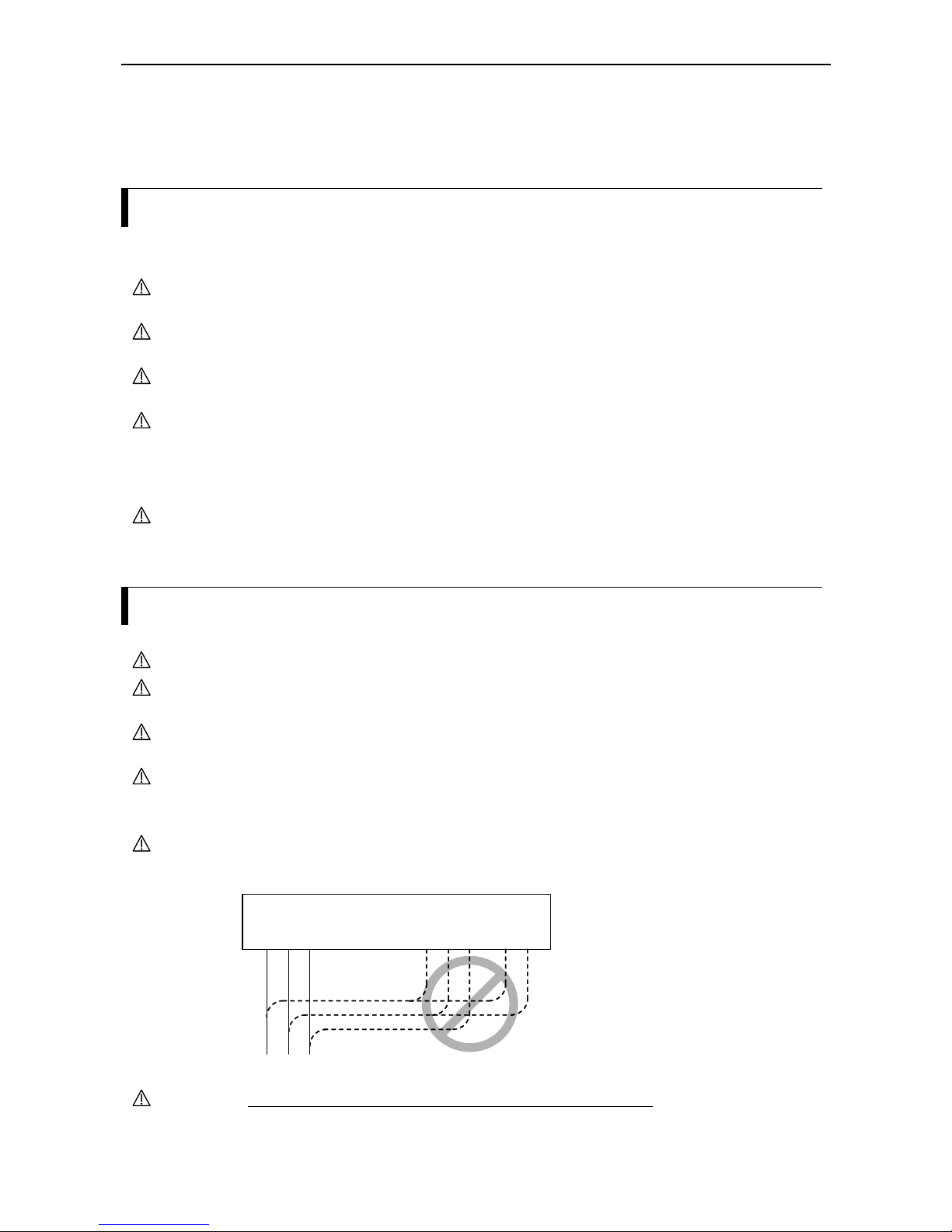
CAUTION Don´t connect AC power supply to the inverter output terminals U, V, and W or fan
supply terminals F, F. Otherwise, there is a danger of injury and/or fire.
INPUTS
(L1) (N)
L1 L2 L3
OUTPUTS
U V W
Note)
Power
su
pply
Note) Terminals L1, N: single phase power supply
Terminals L1, L2, L3: three phase power supply
Not allowed
F F
CAUTION Remarks for using earth leakage circuit breakers in the mains supply:
Frequency inverters with CE-filters (RFI-filter) and screened motor cables have a
higher leakage current against earth. Especially in the moment of switching this can
cause unintentional triggering of earth leakage circuit breakers. Because of the rectifier

Chapter 1 – Safety precautions
1-2
on the input side of the inverter there is the possibility to stall the switch-off function
through amounts of DC current. For these reasons, the following items should be
observed:
Only pulse current sensitive earth leakage circuit breakers which have a short term
delay and a higher trigger current (500mA) should be used. Other components should
be secured with separate earth leakage circuit breakers. Earth leakage circuit breakers
in front of an inverter´s rectifier are not an absolute protection against direct touching.
CAUTION Each phase of the power supply has to be provided with a fuse. Otherwise, there is a
danger of fire.
Control and operation
WARNING Be sure to turn on the input power supply only after closing the front case. While
being energized, don´t open the front case. Otherwise, there is a danger of electric
shock.
WARNING Never operate the switches with wet hands. Otherwise, there is a danger of electric
shock.
WARNING If the retry mode is selected, the inverter may suddenly restart during a stop which
was caused by a trip. In such a case, be sure not to approach the machine. Provisions
have to be taken that the driven motor or machine does not endanger personnell even
in the case of a sudden restart. Otherwise, there is a danger of injury.
WARNING Even if the power supply is cut off for a short period of time, the inverter may restart
operation after the power supply has recovered if the operation command is given. If
this may incur danger to personnell, provisions have to be made in order to prevent a
restart after power recovery. Otherwise, there is a danger of injury.
WARNING The STOP key is effective only if the corresponding parameters have been set.
Otherwise, there is a danger of injury.
WARNING If a reset is carried out following a trip condition the motor will restart if the
operation command has been given. Be sure to acknowledge this trip condition with
a reset only after confirming that no operation command is active. Otherwise, there
is a danger of injury.
WARNING When the power to the inverter is turned on while the operation command is active
the motor starts immediately. So before turning power supply on be sure to confirm
that no operation command is active.
WARNING If the inverter has been configured for the stop command not to be given using the
STOP key, pressing the STOP key does not stop the motor. In this case a separate
emergency stop switch is necessary.
CAUTION Operate the motor and machine connected to the inverter only within the
manufacturer´s speed specifications. Otherwise, there is a danger of injury.
CAUTION If a motor is to be operated at a frequency higher than the standard setting value of
50 or 60Hz, be sure to check the allowable speed of the motor and the machine
with each manufacturer, and operate them only after getting their consent.
CAUTION Check the following during and after the test run. Otherwise, there is a danger of
machine breakage:
Was the short cut bar between terminals +1 and + removed by mistake?
Was the running direction of the motor correct?
Was the inverter tripped during acceleration or deceleration?
Were the indications of the rpm and the frequency meter correct?
Were there any abnormal motor vibrations or noise?
Chapter 1 – Safety precautions
1-3
Maintenance and inspection
WARNING Before carrying out maintenance and inspection wait for at least five minutes after
having turned off the input power supply. Otherwise, there is a danger of electric
shock.
WARNING When removing connectors (e.g. from fans and printed circuit boards) never pull the
attached wires. Otherwise, there is a danger of fire due to wire breakage and/or
injury.
Others
CAUTION Withstand voltage tests and insulation resistance tests (megger tests) are executed
before the units are shipped, so that there is no need to conduct these tests before
operation.
CAUTION Do not attach or remove wiring or connectors when power is applied. Also, do not
check signals (e.g. using a multimeter) during operation.
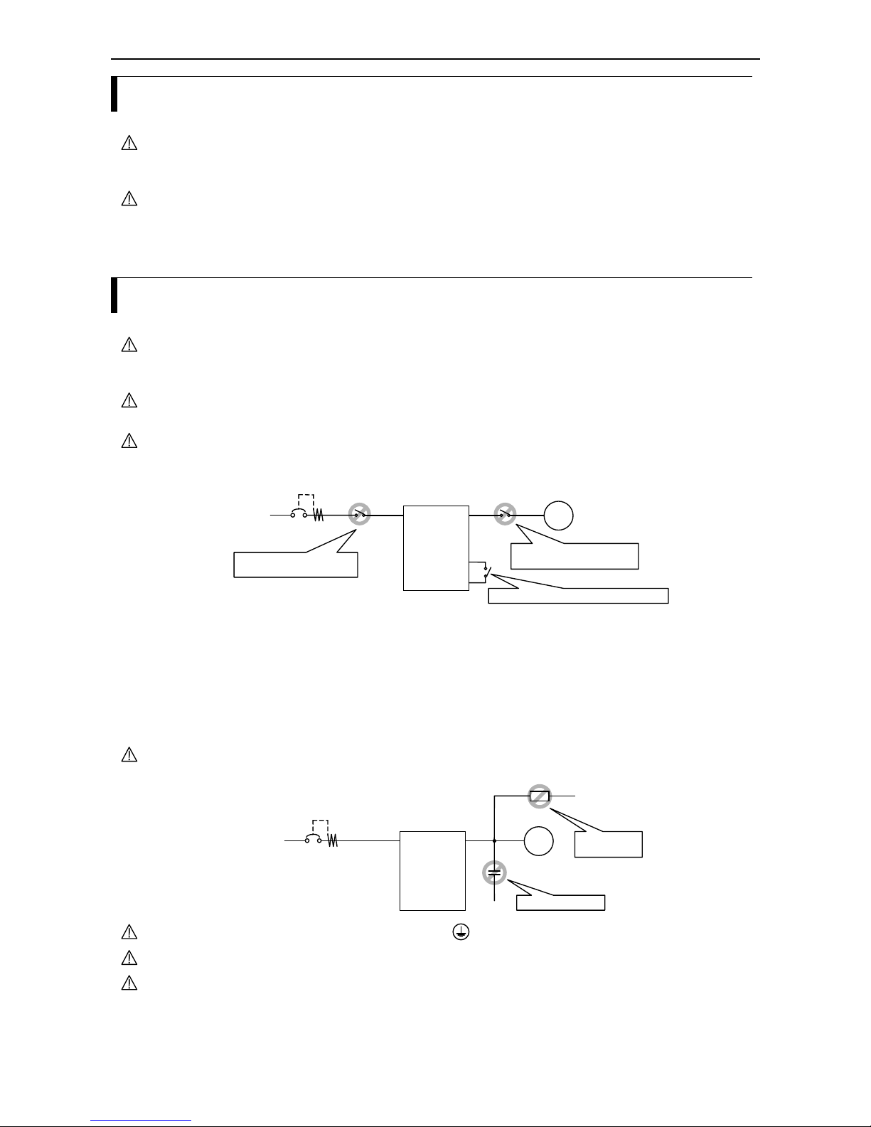
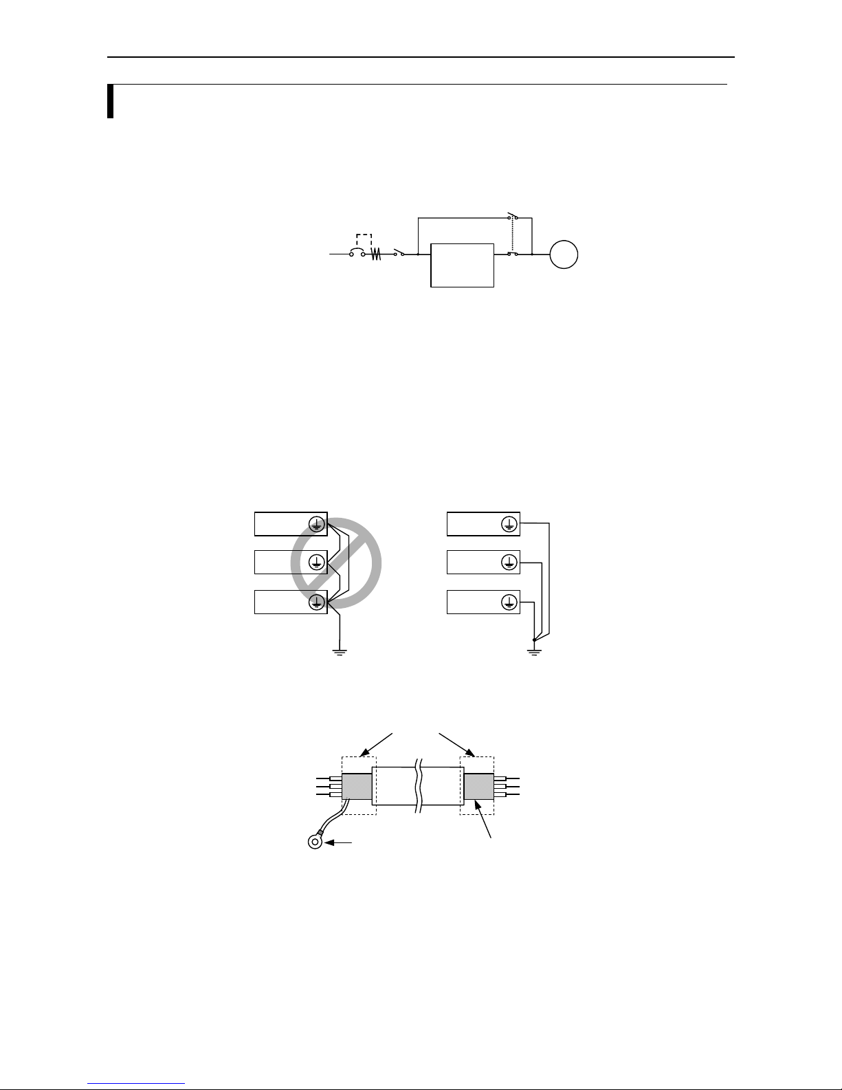
CAUTION Never stop motor operation by switching off the electromagnetic contactors on the
primary or secondary side of the inverter.
Motor
Inverte
r
Earth leakage
circuit breaker
L1(L1)
L2
L3(N)
T1(U)
T2(V)
T3(W)
Powe
r
supply
S2
FW
P24
CORRECT: Start and stop using FW terminal
S1
WRONG: Start and stop using
secondary side contactor
WRONG: Start and stop using
primary side contactor
When there has been an instantaneous power failure, and if an operation instruction
has been given, then the inverter may restart operation after the power failure has
ended. If there is a possibibility that such an occurrence may harm humans, then install
an electromagnetic contactor on the primary (power supply) side of the inverter, so
that the circuit does not allow automatic restarting after the power supply has
recoverd. If the optional remote operator is used and the retry function has been
selected, this will also cause automatic restarting when an operation instruction has
been input, so please be careful.
CAUTION Do not insert leading power factor capacitors or surge absorbers between the output
terminals of the inverter and the motor.
Motor
Inverte
r
Earth leakage
circuit breaker
L1(L1)
L2
L3(N)
T1(U)
T2(V)
T3(W)
Powe
r
supply
WRONG: Capacitor
WRONG:
Surge absorber
CAUTION Be sure to ground the grounding terminal properly.
CAUTION Before inspecting the unit wait at least five minutes before opening the inverter .
CAUTION PROTECTION AGAINST NOISE INTERFERENCE FROM THE INVERTER
L100IP series inverters use many semiconductor switching elements such as
transistors and IGBTs. For this reason, a radio set or measuring instrument located
near the inverter is susceptible to noise interference. To protect the instruments from
erreneous operation due to noise interference produced by the inverter, they should be
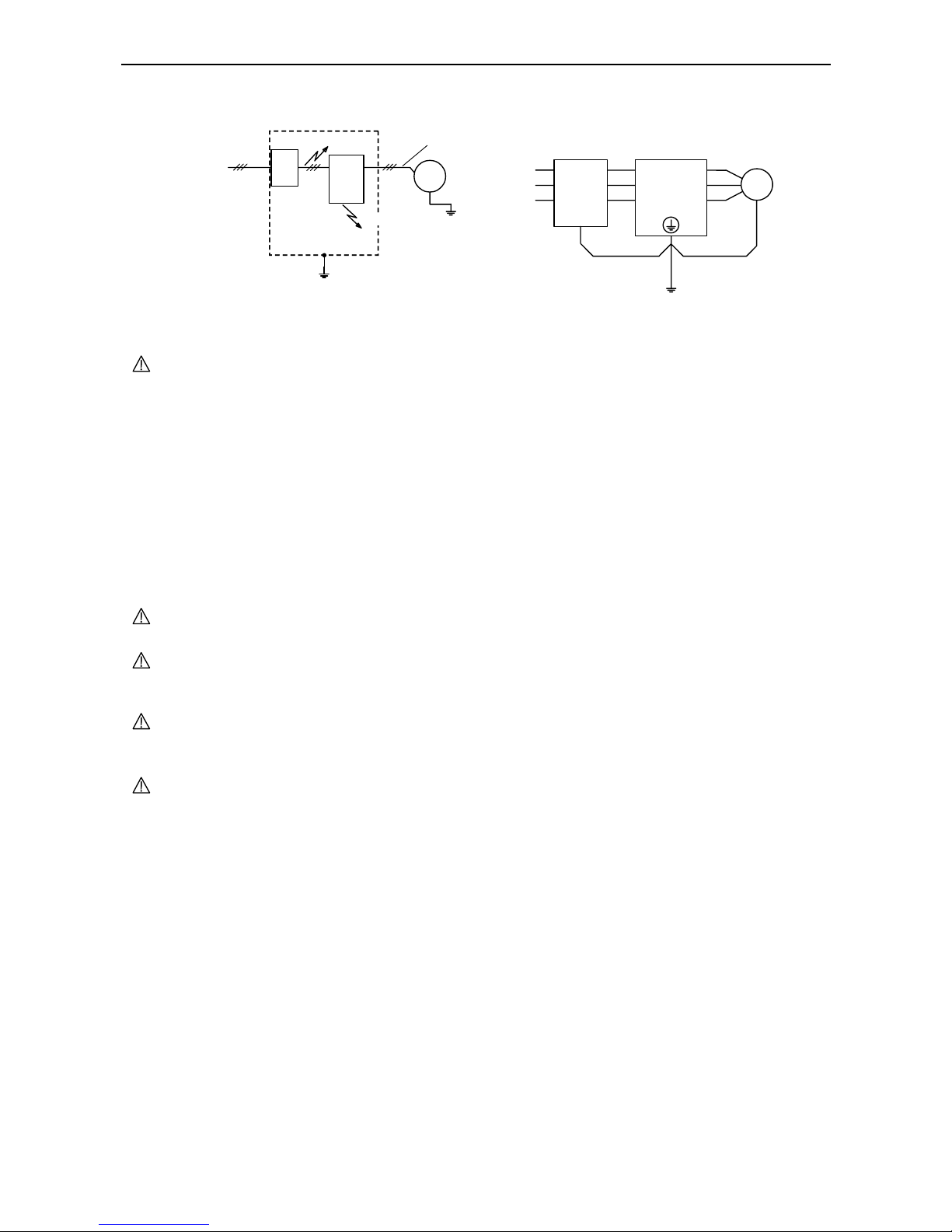
Chapter 1 – Safety precautions
1-4
installed well apart from the inverter. It is also effective to shield the whole inverter
structure (refer to figure below, left part).
Motor
Inverte
r
L1(L1)
L2
L3(N)
T1(U)
T2(V)
T3(W)
R2
S2
T2
Power
supply
R1
S1
T1
EMI filter +
Grounding
Inverter
EMI
filter
Motor
Power
supply
Noise
Noise
Grounded
frame
Completely ground the frame
with as short a wire as possible.
Grounded piping
or shielded wire
Added EMI filter on the input side of the inverter also reduces the effect of noise from
commercial power lines on external devices (refer to figure above).
CAUTION EFFECTS OF DISTRIBUTER LINES ON INVERTERS
In the cases mentioned below involving a general purpose inverter, a large peak
current flows on the power supply side, sometimes destroying the converter module:
A) The unbalance factor of the power supply is 3% or higher.
B) The power supply capacity is set at least ten times greater than the inverter
capacity (i.e. 500kVA or more)
C) When abrupt power supply changes are to be expected. Some examples:
1) Several inverters are interconnected using a short bus to the same power
supply.
2) A thyristor converter and an inverter are interconnected using a short bus.
3) An installed power factor compensating device is connected or disconnected.
In the cases mentioned above we recommend installing an AC reactor of 3% voltage
drop at rated current with respect to the supply voltage on the power supply side.
CAUTION When an EEPROM error occurs (trip E 08) all parameter values have to be checked
for correctness (especially the RS input).
CAUTION When the intelligent digital inputs FW or RV are configured as normally closed
contact (standard setting is normally open), then the inverter starts automatically. Do
not configure these inputs as normally closed inputs unless absolutely necessary.
CAUTION Factory setting of the carrier frequency is different for diferent types of the inverter.
This setting is at the same time also highest allowable carrier frequency without
derating output power. See bottom of the terminal cover for reference.
GENERAL NOTICE
In all the illustrations and figures in this manual, covers and safety devices are
occasionally omitted in order to better describe the details. When the inverter is
operated make shure that all the covers and safety devices are placed in their correct
positions.
Chapter 2 – Inspection upon unpacking
2-1
Chapter 2 – Inspection upon unpacking
Please check the shipment by the time of delivery for damages and completeness. Check that the inverter and
the accompanying instruction manual has been provided. Using the specification label attached to the side of
inverter make sure that the inverter model delivered is the one you ordered.
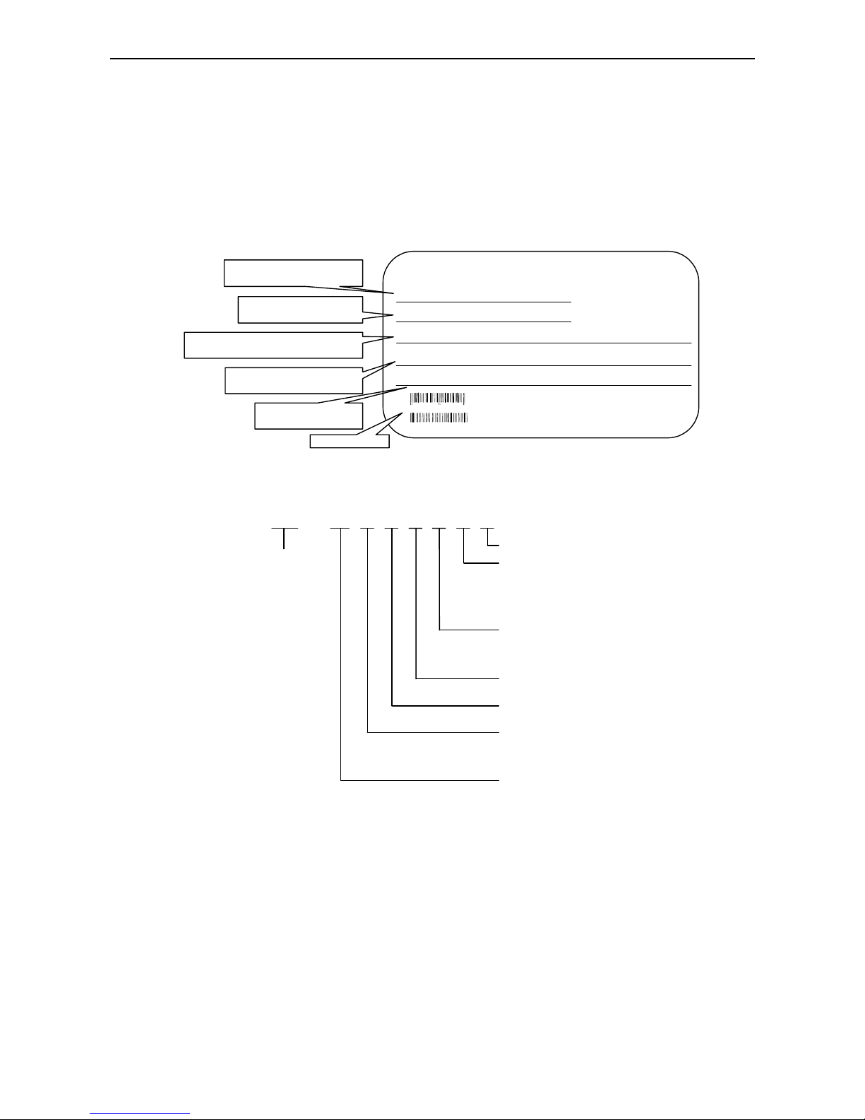
The specifications included on the specification label are described below:
Model : L100IP – 007NFE 510
kW/HP: 0.75 / 1
Input : 50,60Hz 200-240V 1 Ph 9.0A
Hitachi Industrial Equipemnt Systems Co,. Ltd.
MADE IN SLOVENIA
Output : 1-360Hz 200-240V 3 Ph 4.0A
Serial No. : 030300067 Date: 0403
HITACHI
Model designation:
(example for L100IP-007NFE 510)
Applicable motor capacity
(example: 0.75kW/1HP)
Inverter input specifications:
Frequency, voltage, numbe r of phases, current
Inverte r outp ut specifications :
Frequency, voltage, rated current
Manufac turing number,
date (example: April 2003)
8310793 298046
030300067
EAN code
www.hitachi-ds.com (Hitachi Europe GmbH)
In the illustration below, the contents of the model designation used for L100 series inverters is explained:
L100IP - 007 H F E 5
Inverter series
Distribution for
(E: Europa U: USA)
Type of inverter
(F: with digital operator)
Input voltage
(N: 200V single phase)
(H: 400V three phase)
Motor capacit
y
004: 0.40kW 040: 4.00kW
007: 0.75kW 055: 5.50kW
015: 1.50kW 075: 7.50kW
022: 2.20kW
1
0
Option
Input side
1: EMI filter
2: AC reactor
3: EMI filter & AC reactor
Protection class
0: IP00 5: IP54
2: IP20 6: IP65

Chapter 2 – Inspection upon unpacking
2-2
Chapter 3 – Appearance and names of parts
3-1
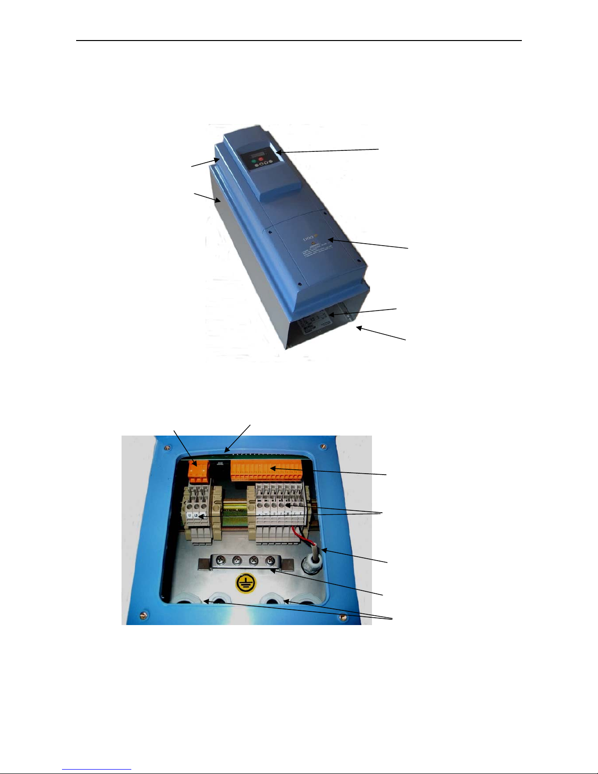
Chapter 3 – Appearance and names of parts
Terminal cover revealed:
Specification label
Terminal cover
Digital operator
Casing – plastic part
Casing – metal part
Fan inside
(air inlet)
Cable glands
Grounding terminal (PE)
Mains circuit terminals
Fan cable
Control terminals
Serial interface
Alarm terminals

Chapter 3 – Appearance and names of parts
3-2

Chapter 4 – Installation
4-1
Chapter 4 – Installation
Explanation of IP54 protection provided by enclosure
Generally, the enclosure must provide sufficient protection for persons who use them and for equipment itself.
IP54 enclosure provides protection to some extent and it is not foreseen for very severe environmental
conditions. Here is the explanation of the two digits:
Protection of persons against access to hazardous parts inside the enclosure indicated by the first
characteristic numeral 5:
Protected against access to hazardous parts with wire.
Protection of the equipment inside the enclosure against ingress of solid foreign objects indicated by the
first characteristic numeral 5:
Dust-protected: Ingress of dust is not totally prevented, but dust shall not penetrate in a quantity to interfere with
satisfactory operation of the apparatus or to impair safety.
The inverter shall not be exposed to severe environmental conditions for more than 8 h (test condition).
Protection of the equipment inside the enclosure against harmful effects due to the ingress of water
indicated by the second characteristic numeral 4:
Protected against splashing water: Water splashed against the enclosure from any direction shall have no harmful
effects.
The inverter shall not be exposed to splashing water for more than 10 minutes (test condition).
The unit is not intended for outdoor usage.
Other than in the time specified above, inverter must be operated in the condition of 90% humidity or less.
WARNING the above explanation is intended as an indication. Refer always to the a.m.
standard in the case of any doubt.
Chapter 4 – Installation
4-2
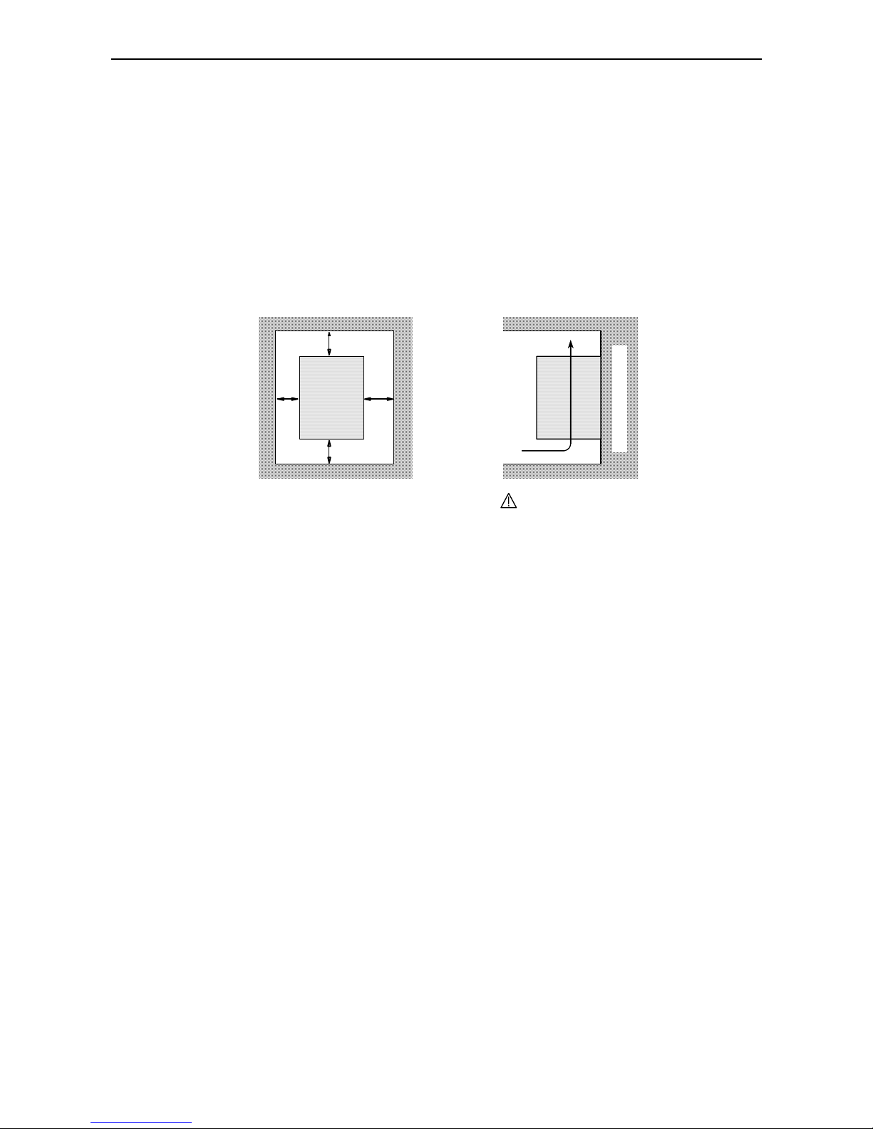
The inverter must be mounted vertically on a non-flammable wall in order to prevent from overheating and
fire. The minimum clearances to the surrounding walls shown in the figure below must be complied with to
ensure a good ventilation. Foreign matter (especially conductive objects) must nut be dropped into the
inverter since they not only cause malfunction and damage but may also lead to electrical and fire hazards.
Cover all ventilation holes on the inverter during installation so that no foreign objects can enter the inverter.
Be sure to remove those covers from the inverter before you put the inverter to work.
approx. 10cm
approx. 1c
m
approx.
1cm
Inverter
Air flow
The inverter must be installed vertically
(do not install it on the floor or horizontally)
Wall or mounting surface
The mounting base must be a non-
flammable material (e.g. metal)
approx. 10cm
The minimum clearances to the surrounding walls shown in the figure are only meant for reference. A more
compact installation (back to back or side by side) may well be possible and should be discussed with
Hitachi. Please always leave enough room for the teminal cover to be opened without problems in order to
connect wires to the control terminals.
The ambient temperature should be in the range of -10°C to 40°C. Higher ambient temperature causes shorter
inverter life. So if there is hot equipment in the vicinity of the inverter, keep it away from the inverter as far
as possible.
The end application must be in accordance with the BS EN 60204-1 standard.
Chapter 5 – Wiring
5-1
Chapter 5 – Wiring
CAUTION Fasten the screws with the specified fastening torque so that they will not loosen
unintentionally. Check all terminals for loose screws. Otherwise there is a danger of
fire.
CAUTION Remarks for using earth leakage circuit breakers in the mains supply
Frequency inverters with CE-filters (RFI-filter) and screened motor cables have a
higher leakage current against earth. Especially in the moment of switching this can
cause unintentional triggering of earth leakage circuit breakers. Because of the rectifier
on the input side of the inverter there is the possibility to stall the switch-off function
through amounts of DC current. For these reasons, the following items should be
observed:
Only pulse current sensitive earth leakage circuit breakers which have a short term
delay and a higher trigger current (500mA) should be used. Other components should
be secured with separate earth leakage circuit breakers. Earth leakage circuit breakers
in front of an inverter´s rectifier are not an absolute protection against direct touching.
CAUTION Each phase of the power supply has to be provided with a fuse. Otherwise, there is a
danger of fire.
CAUTION As for motor leads, earth leakage breakers, and electromagnetic contactors, be sure to
use the ones that have the correct rating. Otherwise, there is a danger of fire.
CAUTION Make sure that the mains supply leads are reliably fixed.
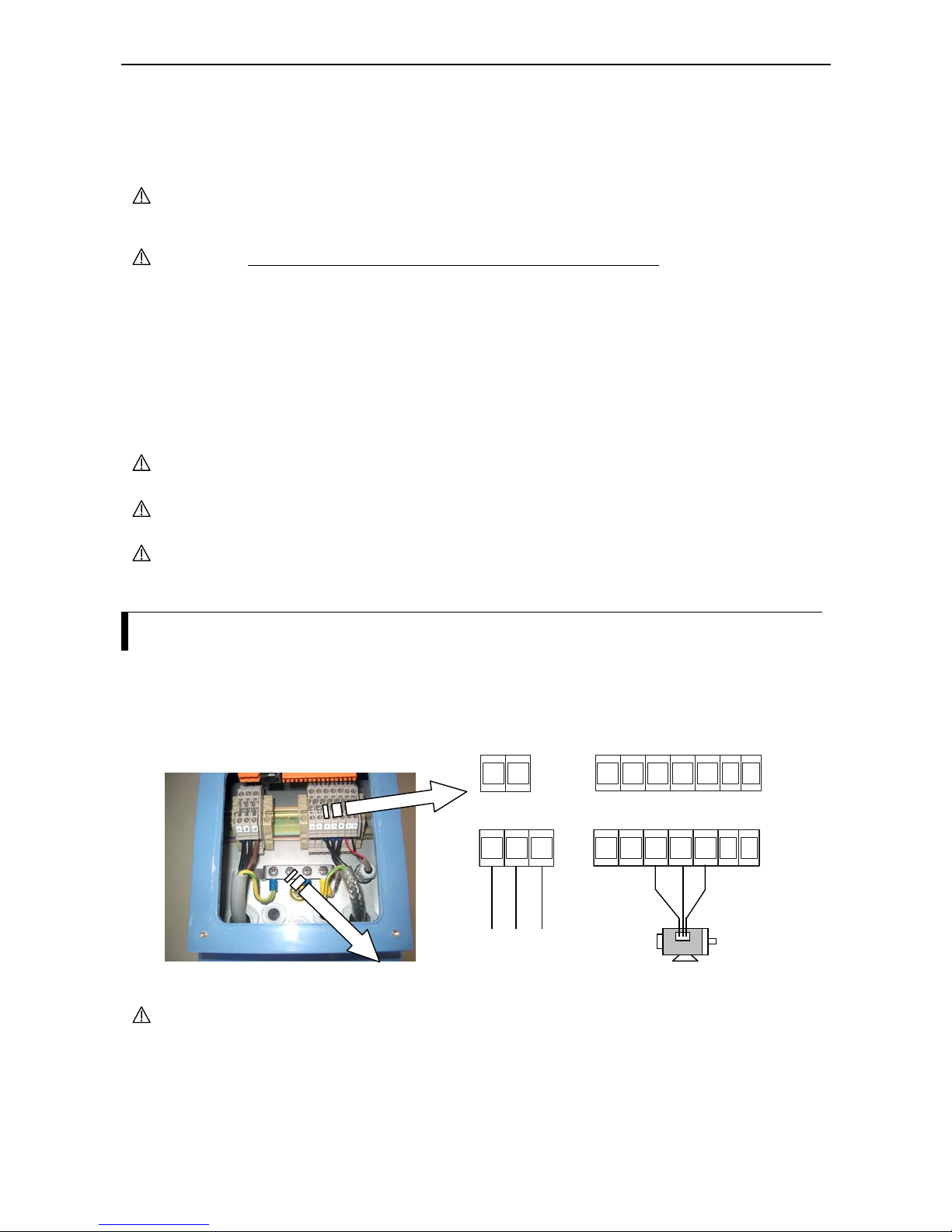
Wiring the power supply and motor
In order to connect cables to the power supply and other terminals the terminal cover has to be opened. For
this, first of all the four corresponding screw has to be loosened. The location of the terminals is depicted in
the figure below:
CAUTION Don’t disconnect wires attached to F terminals (fan power supply), otherwise
inverter may overheat. In case the wires are exchanged, the fan doesn’t work. This
terminals cannot be used for the power supply for external device.
When connecting cables, the following details have to be considered:
1) Power supply cables must only be connected to the terminals L1, L2, L3 or L, N.
2) Refer the page 5-5 for wiring equipment and options.
L1 L3L2 +VUFF-W
Motor
To the power supply
Mains circuit terminals
LN +VUFF-W
NFE:
HFE:
Grounding terminal (PE)

Chapter 5 – Wiring
5-2
3) If more than one motor is to be driven by a single inverter, thermal relays have to be provided for each
motor.
Therma l relay
L100IP
4) The leads from the power supply must be connected to the mains circuit terminals as follows:
Connect single phase power supply (50/60Hz) to terminals L1, N.
Connect three phase power supply (50/60Hz) to terminals L1, L2, L3.
Wiring the control terminals
The following figure shows the location of the control terminals. The exact use of each of the control
terminals is described later in this chapter.
The figure below contains an example for control terminal wiring:
Reset (RS)
FA1
Prevention of
restart (USP)
Jogging run (JG)
Reverse run (RV)
Forward run (FW)
24VDC
(Common fo
r
inputs)
RUN
Potentiometer
(1k-2kOhm)
for frequency
set value
Frequenc
y
meter
24V DC,
max. 50 mA
L 3 4 5 2 1 H O OI FML 12 11
NOTE: Function of digital inputs and outputs can be changed
Control terminals
Alarm circuit
terminal
REMOVABLE
CONNECTOR
Control circuit terminal
REMOVABLE CONNECTOR
L
3
4
5
2 1 H
O OI
FM L 12 11
Chapter 5 – Wiring
5-3
General remarks
When connecting cables, the following items must be observed:
- When changing the power supply of the motor between the inverter and commercial power line, be sure
to install mechanically interlocked switches (S1 and S2) as shown in the figure below:
Motor
Inverter
Earth leakage
circuit breakers
L1 (L)
L2
L3 (N)
U
V
W
Power
supply
S1
S2
- Install an earth leakage breaker at the input of the inverter. Select an earth leakage breaker which has a
short term delay and a higher trigger current.
When the cable between the inverter and the motor is more than 10 meters long, the thermal relay may
malfunction due to high-frequency waves. To prevent this, install an AC reactor on the output side of the
inverter or use a current sensor rather than a thermal relay.
- In case a relay is connected to the digital output terminals 11 or 12 be sure to install a surge absorbing
diode in parallel to the relay. Otherwise the surge voltage created when the relay goes on or off may
damage the output circuit.
- Be sure that the specified grounding is carried out. Separate the inverter´s grounding pole from those of
other heavy electric machinery and avoid using common grounding poles when multiple inverters are
employed.
Inverter 1
Inverter 2
Inverter 3
Ground ing poi nt Ground ing poi nt
WRONG CORRECT
Inverter 1
Inverter 2
Inverter 3
- Use a twisted and shielded wire when connecting signal lines to the control terminals and cut the
shielded covering as shown in the figure below. Make sure that the length of the signal line is 20 m or
less. If the line must be longer than 20 m then an appropriate signal amplifier should be used.
Frame ground
Isolate here
No grou nding
necessary here
- Use relays which are capable of reliably switching at a voltage of 24VDC and a current of 3mA.
- Install the mains circuit cables at a safe distance from the control circuit cables. If the mains circuit
cables and the control circuit cables have to cross each other, this should be done at an angle of 90
degrees because interference can be minimized in this case.
Chapter 5 – Wiring
5-4
90°-angle
Mains circuit power cable
(L1, L2, L3 (L, N), U, V, W, +1, +, - )
Signal line (H, O, OI, L, FM, 1,
2, 3, 4, 5, 11, 12, CM2, P24)
Separate by 10cm or more
- Do not short circuit the terminals P24 and L, H, OI, or FM by mistake, because this may cause a
malfunction.
- Do not short circuit the terminals H and L because this may cause a malfunction.
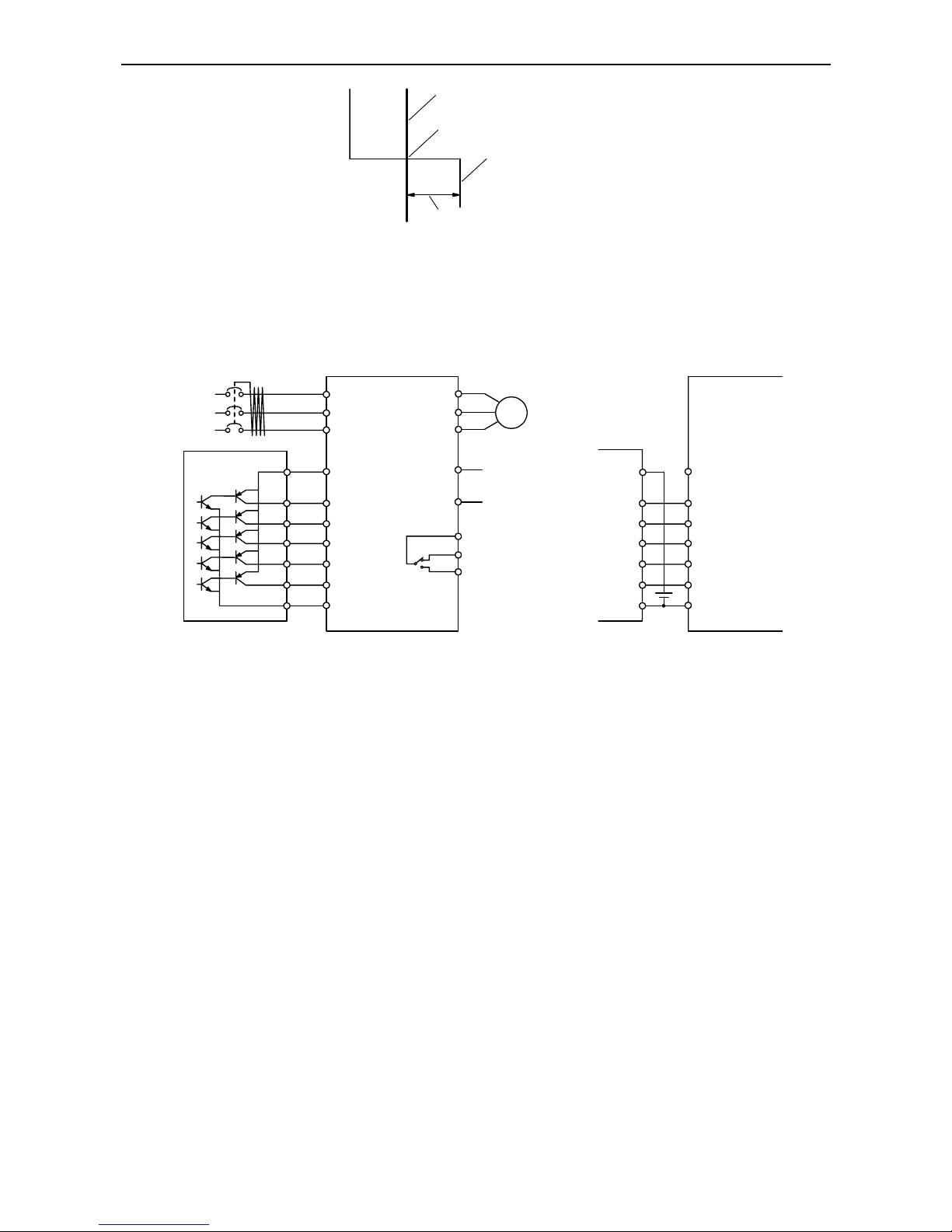
The following figure shows an example for connecting a driver-IC to the digital inputs when using the
inverter´s internal 24VDC power supply terminal (left half of figure below) and when using a separate
external 24VDC power supply (right half of figure below).
L100IP series
frequency inverter
L1 (L)
L2
L3 (N)
U
V
W
1
2
3
4
5
L
P24
AL0
AL1
AL2
Motor
+
Alarm
terminals
1
2
3
4
5
S
COM
Transistor output driver
YTS48 or similar
24VDC
(
Note)
Note: Do not short circuit the terminals P24 and L by mistake because this may lead to a malfunction.
-
Terminals for
braking unit
1
2
3
4
5
L
P24
1
2
3
4
5
S
COM
24VDC
(
Note)
24V
b
attery
L100IP series
frequency inverter
(terminals not shown here
are exactly like those of
the inverter shown in the
left part of this figure).
Transistor output driver
YTS48 or similar

Chapter 5 – Wiring
5-5
Wiring equipment and options
CAUTION A switch or circuit breaker shall be included in the building installation. It shall be
marked as the disconnecting device for the equipment and should meet the
requirements of the IEC947-1 and IEC947-3 standard. Ratings should be in
accordance with table below. For single phase there should be a double pole and for
three phase there should be a three pole disconnecting device. The switch or circuit
breaker should be near the equipment (close proximitly to the equipment and in easy
reach to the operator).
CAUTION Provide the wiring equipment in accordance with the safety codes required by
jurisdictional authorities (IEC example: supply wires should meet the requirements
of the IEC 60227 or IEC 60245... They should be made of suitable heat-resistant
material). If specified in standards or laws and regulations, follow their istructions.
In the following table some guidelines for choosing an appropriate wire gauge are
presented:
Cable specifications
600V fuse to be
used
(rated current / A)
Input
voltage
Motor
output
(kW)
Inverter
model
Power lines
Cable
diameter
Signal
lines
0.4
L100IP-004NFE
L100IP-004NFU
1.5 mm
2
(AWG 15)
10 A
0.75
L100IP-007NFE
L100IP-007NFU
2.5 mm
2
(AWG 13)
16A
1.5
L100IP-015NFE
L100IP-015NFU
4.0 mm
2
(AWG 11)
25 A
200V single phase
2.2
L100IP-022NFE
L100IP-022NFU
4.0 mm
2
(AWG 11)
40 A
0.75
L100IP-007HFE
L100IP-007HFU
1.5
L100IP-015HFE
L100IP-015HFU
2.2
L100IP-022HFE
L100IP-022HFU
1.5 mm
2
(AWG 15)
10A
4.0
L100IP-040HFE
L100IP-040HFU
2.5 mm
2
(AWG 13)
16A
5.5
L100IP-055HFE
L100IP-055HFU
400V three phase
7.5
L100IP-075HFE
L100IP-075HFU
4.0 mm
2
(AWG 11)
10-17mm
Shielded wire (max. 1.5mm
2
)
*)
cable diameter 5-10 mm.
25A
Notes:
- Field wiring connections for PE wire must be made by a certified closed-loop terminal connector sized
for the wire gauge involved. The connector must be fixed using the crimp tool specified by the connector
manufacturer.
- Only use a fuse that has the appropriate rated current.
- Be sure to use bigger wires for mains circuit cables and motor cables if the distance exceeds 20m.
- Tighten firmly the cable gland nuts after pulling through the cable. The round rubber protection is to be
removed before wiring. Leave rubber protectection in unused glads in order to keep IP54 protection.
*)
Use max. 1,5mm2 for the alarm signal wire. The wire stripping length should be approximately 6–7 mm.
Chapter 5 – Wiring
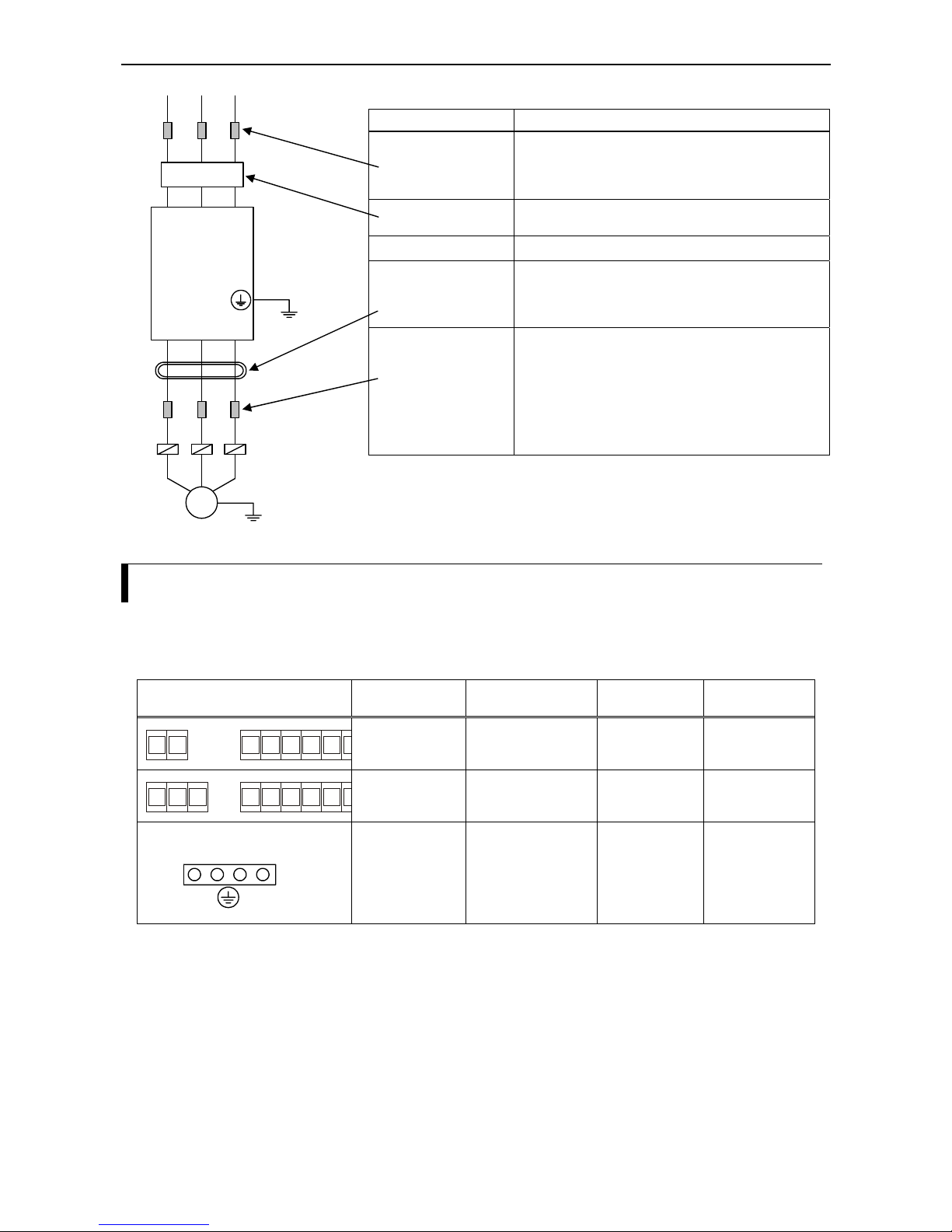
5-6
Part description Function
AC reactor
This part is used when the unbalance ratio is 3% or
more and the power supply is 500kVA or more, and
there are rapid changes in the power supply. This part
also improves the power factor.
EMI filter
(Note)
This part is used to conform with the applicable
EMC standards.
Radio noise filter
This part reduces noise generated at the output of the
inverter (this type of filter supplies an almost perfect
sine shaped output voltage between phase-phase and
phase-PE).
Motor filter
Motors that are driven by an inverter are to a larger
extent subject to voltage fluctuations than motors directly
driven (without inverter) by power lines. An AC reactor
installed between inverter output and motor smoothens
motor run and so reduces torque ripple. When the cable
between the inverter and the motor is too long, this part
also forces the voltage dv/dt to be limited and so protects
the isolation of the motor.
Note: Usage of an EMI filter is necessary for the European EMC
directive, for the Australian C-TICK and others. In comparison, the other
parts mentioned in the table above are not intended for this special use.
Terminals
In the table below the location and dimensions of the power terminals (terminals for power supply and
motor) are listed:
Location of power terminals Inverter model
Screw size
(Screwdriver type)
Cross section
of cable
Tightening
torque range
LN +VUF-W
All NF models
M3
(0.6x3.5mm)
0.5…6mm
2
(AWG 22...10)
0.5…1.0 Nm
L1 L3L2 +VUF-W
All HF models
M3
(0.6x3.5mm)
0.5…6mm
2
(AWG 22..10)
0.5…1.0 Nm
View of grounding terminal
All
M4
(PH2)
Ring or fork type
cable terminal
diameter: 4mm
1.2…1.3 Nm
L1
(L1)
L2
L3
(N)
(T1) U (T2) V (T3)
W
Motor
Thermal
relays
Chapter 5 – Wiring
5-7
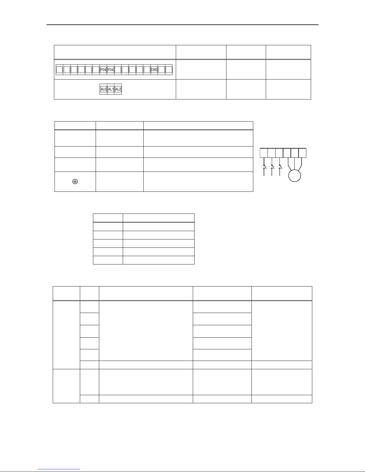
The following table shows the location and dimensions of control and alarm terminals:
Location of terminals
(REMOVABLE CONNECTOR)
Screw size
(Screwdriver type)
Cross section
of cable
Tightening
torque range
M2
(0.4x2.5mm)
0.5…1.5mm
2
(AWG 22...14)
0.2...0.25 Nm
M2.5
(0,6x3,5mm)
0,5-2.5mm
2
(AWG 22..12)
0.4…0.5 Nm
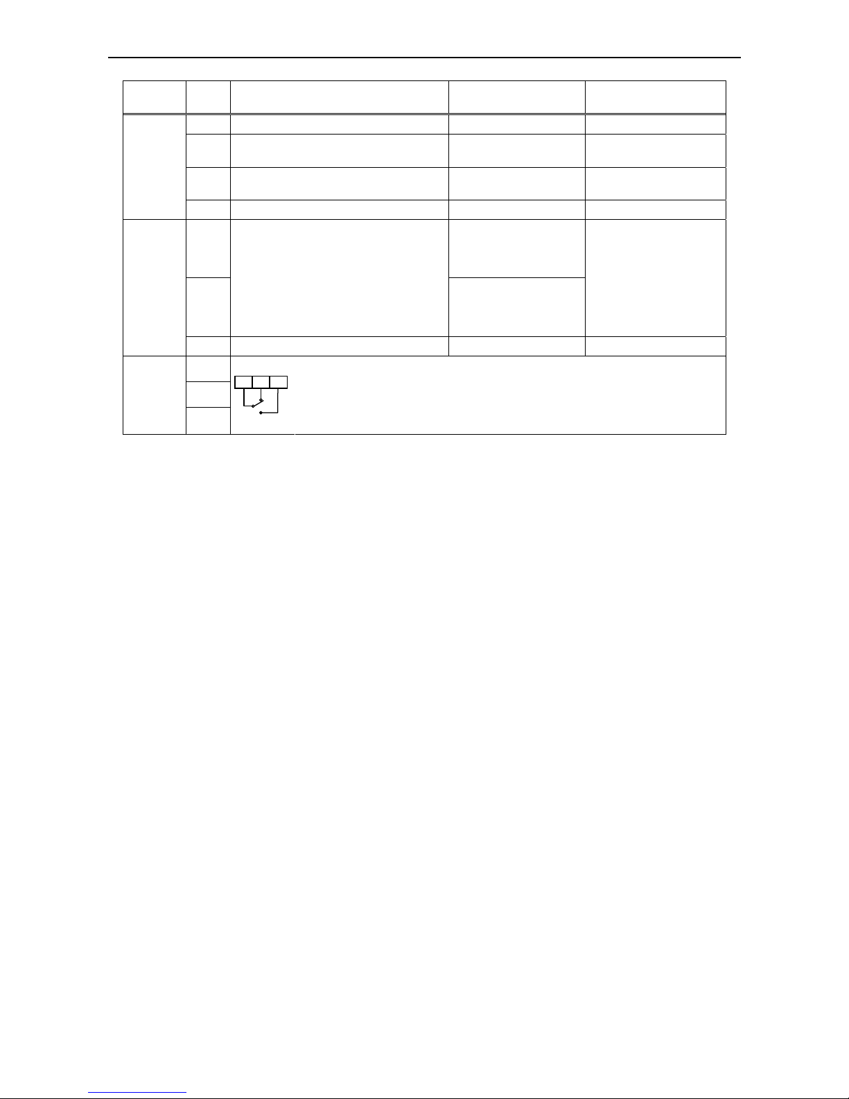
In the following table the purpose of the power terminals is shown:
Terminal symbol Purpose Description
L1, L2, L3
(L, N)
Mains supply
Single phase supply: connect to L, N
Three phase supply: connect to: L1, L2, L3
U, V, W
Inverter output Connect a three phase motor
+, - Braking unit
Connect the optional braking unit (when high
braking torque is required).
Grounding
Ground must be connected to prevent electric shock
should the inverter case carry dangerous voltages
due to a malfunction. Also to connect cable shield.
L1
(L)
L
2
L3
(N)
U
V W
Motor
The following table lists the tightening torque values for tightening the screws:
Screw Torque in Nm
M2 Typ. 0.20 Max. 0.25
M3 Typ. 0.50 Max. 0.60
M3.5 Typ. 0.80 Max. 0.90
M4 Typ. 1.20 Max. 1.30
M5 Typ. 2.00 Max. 2.20
The next table describes the purpose of each control terminal: (To be continued on next page)
Terminal
category
Sym
bol
Purpose Initial setting Remarks
5 Reset input
4
Multistage frequency
input / USP function
3
Multistage frequency
input / use 4-20mA input
2 Reverse run
1
These inputs have different purposes
depending on the user programmed
configuration:
Forward and reverse running command,
up to 4 multistage speed settings,
jogging run, 2nd stage acceleration/decel.,
free run stop, external trip, USP function,
terminal software lock, reset, PTC, input
for choosing current as analogue set value
Forward run
Input closed (ON):
Function active
Input opened (OFF):
Function not active
Input must be ON for a
minimum of 12ms
Digital
Inputs
P24 Common for input signals 24V DC; max. 30mA
FM
Connection of an analogue or digital meter
for measuring frequency;
connection of an analogue meter for
current measurement
Frequency monitor
(analogue)
Monitor
signal
L Common for monitor signal
L 3 4 5 2 1 H
O OI
FM L 12 11
Chapter 5 – Wiring
5-8
Terminal
category
Sym
bol
Purpose Initial setting Remarks
H Reference for frequency command input 10V DC; max. 10mA
O Voltage frequency command
Set value 0-10V;
Input impedance 10k
Ohm
OI Current frequency command
Set value 4-20mA;
Input impedance 250
Ohm
Frequency
command
input
L Common for frequency command input
11
Frequency arrival signal
(signal when reaching
set value)
12
The digital outputs can be user
programmed to provide different signals
for the following situations:
Signal when reaching set value or
passing a configurable frequency;
signal during motor run;
overload signal;
PID deviation signal; alarm signal
Signal during
motor run
Outputs of
open collector type for
connection to a relay
(max. 27V DC and
max. 50mA)
Digital
output
CM2 Common for digital outputs
AL0
AL1
Fault
alarm
output
AL2
AL0 AL1 AL2
Initial setting: During normal operation AL0-AL1 is closed; during a trip condition
or cut off power supply AL0-AL1 is opened (i.e. AL0-AL2 is closed).
Ratings of relay contacts:
Max. 250VAC / 2.5A (resistive) or 0.2A (cos phi = 0.4);
Min. 100VAC / 10mA
Max. 30VDC / 3.0A (resistive) or 0.7A (cos phi = 0.4); Min. 5VDC / 100mA
Chapter 6 – General operation notes
6-1
Chapter 6 – General operation notes
Before starting operation
Prior to the test run, the following items should be checked:
1) Make sure that the power lines (input power supply terminals L1, L2, L3 or L, N) and output terminals
(U, V and W) are connected correctly.
2) Make sure that there are no mistakes in the signal line connections.
3) The grounding terminal must be grounded.
4) Terminals other than those marked as grounding terminals must not be grounded.
5) The inverter must be installed vertically on a non-flammable mounting surface (e.g. steel).
6) Remove any residue from wiring work like stray pieces of wire and others. Also, make sure that no tolls
are left behind.
7) Make shure that the wires connected to the output terminals are not short-circuited or grounded.
8) All the terminal screws must be sufficiently tightened.
9) The configurable maximum output frequency parameter must be chosen in accordance with the
maximum frequency of the connected motor and machine.
Do not carry out any withstand voltage tests because the inverter has a surge absorber between the mains
circuit terminals and the ground.
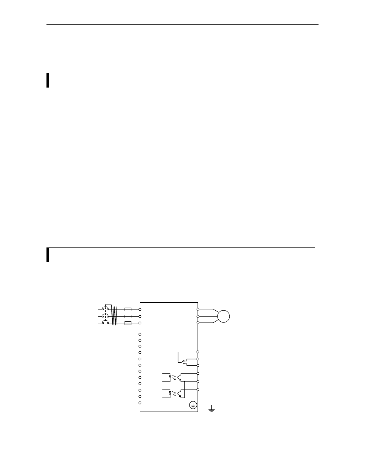
Test run
Below an example for an inverter connection is shown. For the initial tests, frequency adjustment and
forward and reverse running commands should be carried out via the digital operator in order to check the
inverter’s correct functioning.
Power supply
(three phase)
50/60 Hz
Fuses
Earth leakage
circuit breaker
Inverter
L100IP series
L1 (L)
L2
L3 (N)
U
V
W
1
2
3
4
5
L
P24
H
O
OI
L
FM
AL0
AL1
AL2
11
CM2
12
Motor
Ground
400V class:
Three phase 380~460V
200V class:
Single phase 200~240V
Fault alarm signal
Normal state: AL0-AL1
Trip and pow er off: AL0-A L2
Initial setting for maximum
frequency (-FE and -FU series)
is 50 or 60Hz and initial setting
for direction of rotation is
“forward run“.

Chapter 6 – General operation notes
6-2
In order to test the inverter, follow the procedure described below:
1) Turn on power supply to the inverter. The power LED on the digital operator will light up.
2) Set function A 02 to 02.
3) Set function A 01 to 02. Set the corresponding frequency using function F 01.
4) After pressing the RUN key the motor starts to run and the the RUN lamp lights up.
5) The actual frequency can be monitored using function d 01.
6) You can stop the test run by pressing the STOP key.
CAUTION After the test run has been completed, check the following items to ensure that the
motor will not be damaged:
Was the direction of the motor run correct? Was there any trip condition during
acceleration or deceleration? Were there any unusual motor sounds or vibrations?
When a trip occured during the test run due to overcurrent or overvoltage, increase
acceleration or deceleration time.
Chapter 7 – Control circuit terminal functions
7-1
Chapter 7 – Control circuit terminal functions
Overview
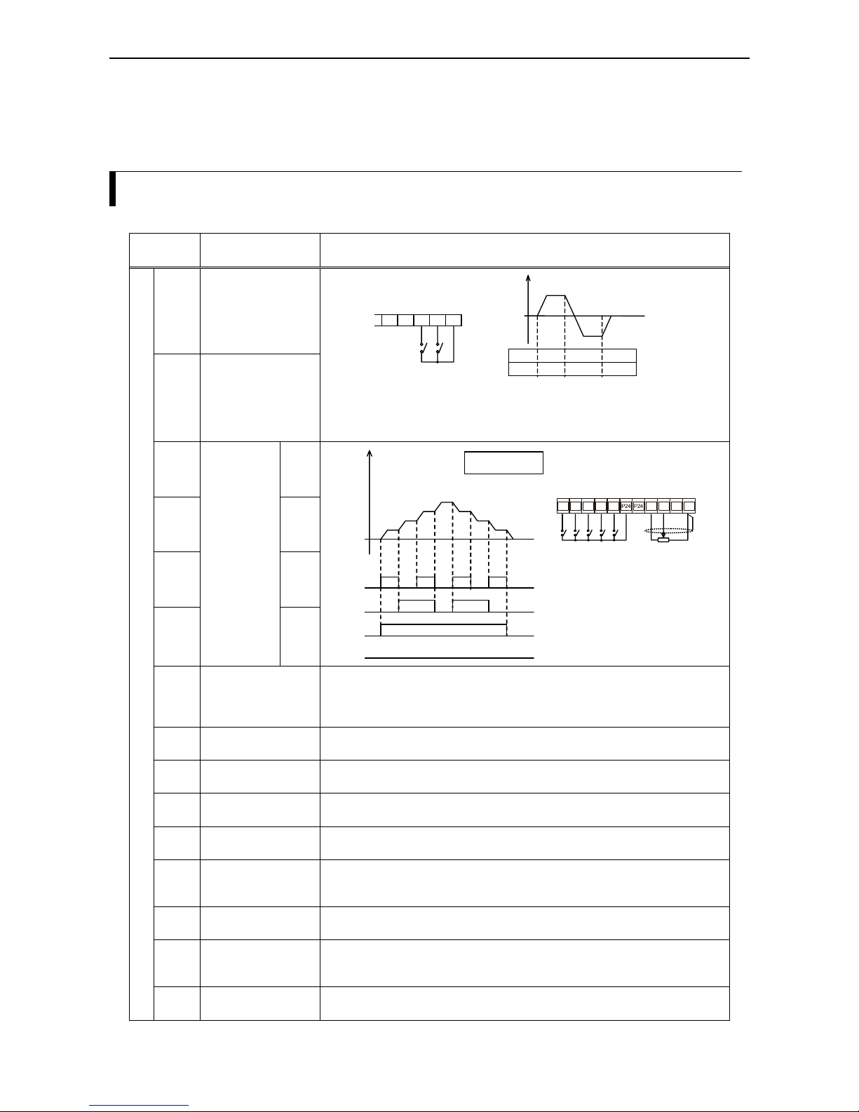
Terminal
symbol
Terminal function Description
FW
(00)
Forward run
(Start/Stop)
RV
(01)
Reverse run
(Start/Stop)
Freque nc
y
FW ON OFF OFF
RV OFF ON OFF
Forward run
Reverse run
4321P24
RV
FW
Input FW closed: Motor starts with forward running direction.
Input FW open: Motor decelerates from forward running.
(same for reverse run using input RV)
Inputs FW and RV both closed: motor decelerates.
CF1
(02)
1
CF2
(03)
2
CF3
(04)
3
CF4
(05)
4
Frequenc
y
CF1
Frequ. 1
Frequ. 2
Frequ. 3
Set value
ON ON ON ON
ON ON
ON
CF2
FW
RV
Example:
4 multistage speeds
Analog set value
2 multistage inputs (CF1 and
CF2) are necessary for 4
different multistage speeds
(3 programmable multistage
speeds plus 1 set value).
FR
S
CF2
CF1
RV
FW
345 2 1 H O OI L
JG
(06)
Jogging run
The jogging run activated using the terminal JG may serve for setting up a machine
in manual operation mode. When a forward or reverse run command is given, the
frequency configured using A 38 is then sent to the motor. For motor stop, one of
three operating modes can be chosen by configuring A 39.
PTC
(19)
Connection of exter-
nal PTC thermistor
Only digital input 5 can be programmed as a PTC thermistor input (using C 05).
The terminal L serves as common for the thermistor input.
AT
(16)
Activate input OI (current set value 4-20mA)
When the AT input is activated, then the set value will be a 4-20mA current
that has to be supplied at the terminals OI and L.
2CH
(09)
2. stage acceleration /
deceleration
Using this input the second stage acceleration and deceleration time
configured using A 92 and A 93 is activated.
FRS
(11)
Free run stop
function
When the terminal FRS is turned on, frequency to the motor is
switched off and the motor runs free.
EXT
(12)
External trip
When the terminal EXT is turned on, the inverter enters the trip state, stops output
to the motor, and displays E 12. The trip condition can be acknowledged, among
others, using the RS input.
USP
(13)
Prevention of restart
When the USP input is on, the motor does not restart when power supply recovers
following a power supply failure and a running command is active at the same time.
RS
(18)
Reset
A trip can be acknowledged by activating the RS input. If a reset is given during
normal inverter operation, the motor runs free. The RS input is always a normally
open contact and cannot be configured as normally closed input.
Programmable digital inputs 1 through 5
SFT
(15)
Software lock
When the SFT input is turned on, the configured parameters are protected
from being overwritten.
Pro
g
rammable multista
g
e s
p
eeds

Chapter 7 – Control circuit terminal functions
7-2
Terminal
symbol
Terminal function Description
P24
24V DC common for
digital inputs
Common terminal for the intelligent digital inputs
H
10V reference voltage
for analog set value
(using potentiometer)
O
Frequency set value
analog input (0-10V)
OI
Frequency set value
analog input (4-20mA)
Frequency command
L
Common terminal
for analog set value
inputs
HOOIL
Pot (1k – 2K)
HOOIL
0 - 9,6V DC (rated value 10V)
Input impedance 10k Ohms
HOOIL
4 - 19,6mA DC (rated value 20mA)
Input impedance 250 Ohms
Set value configured
usin
g p
otentiometer:
Set value configured
using voltage input:
Set value configured
using current input:
The OI input (set value using analog current 4..20mA) will only be used if
the input configured as AT has been closed before. If no digital input has
been configured as an AT input then the set values that are present at terminals O and OI will be added.
FM Frequency monitor
Using the FM output the output frequency can be monitored and displayed using
an external analog or digital meter. If needed, the motor current can be displayed
instead of the frequency.
Monitor
L 0V Common terminal for the FM output
FA1
(01)
FA2
(02)
Frequency arrival
signals
Frequenc
y
FA1 active
Frequenc
y
FA2 active
f
2
f
1
f
soll
When a digital output is configured as FA1 then a signal
is output as long as the output frequency is held constant
at set value. With a digital output being configured as
FA2, a signal will be output as long as the actual output
frequency is above the values set under C 42 and C 43.
RUN
(00)
RUN signal
The RUN signal is active as long
as the motor is running.
OL
(03)
Overload signal
The OL signal will be output when the actual motor current
is above the threshold set under C 41.
OD
(04)
PID deviation signal
The OD signal will be output when the threshold set under
C 44 (level of PID deviation) is being passed.
Programmable digital outputs 11 and 12
AL
(05)
Alarm signal The alarm signal is output in case a trip condition occurs.
Connection of a
signal relay to digital
output 11 or 12:
CM2
12 11
Open collector
type output
(max. 27VDC, 50mA)
CM2 0V
This is the 0V common for the programmable digital outputs 11 and 12. These
open collector type outputs are isolated using photocouplers and are separated
from L common.
AL0
AL1
AL2
Alarm terminals
During normal trouble-free operation the terminals AL0 and AL1 are shorted.
During a trip condition or while power to the inverter is off the terminals AL0 and
AL2 are shorted instead.
Absolute maximum relay contact ratings:
250VAC; max. load of 2.5A (purely resistive) or 0.2A (at an cos phi of 0.4)
30VDC; max. load of 3.0A (purely resistive) or 0.7A (at an cos phi of 0.4)
Minimum relay contact ratings:
100VAC at a load of 10mA or 5VDC at a load of 100mA

Chapter 7 – Control circuit terminal functions
7-3
FM terminal
Terminal function
This terminal is used for connecting an analog voltmeter or a digital frequency meter and thus to monitor and
display output frequency. Alternatively, motor current can be monitored instead (when output current is
selected the FM terminal can only supply an analog signal).
1) Frequency display using analog output signal
The analog output signal is a pulse train whose period remains constant. The width of the pulses ist
proportional to the actual output frequency (0 to 10V represent 0Hz to maximum frequency):
0 to 10V
1mA
t
T
10V
T
t
=variable
T=4ms
(
consta nt
)
Adjustment of this signal is done using function b 81. The signal accuracy following adjustment is
+/-5%
2) Frequency display using digital output signal
The frequency of this signal is proportional to the output frequency. The duty cycle is approximately
50%:
Digital fre-
quency meter
10V
f
T = 1/(outpu
t
fre
q
uency*factor
)
T
The signal frequency equals the actual output frequency multiplied by the factor configured under b 86.
3) Motor current display using analog output signal
This signal is identical to the one described under 1). The width of the pulses is proportional to the actual
motor current. The maximum voltage of 10V is reached when the motor current is two times the inverter
rated current. The signal accuracy is +/-20%. The connection to a meter is described under 1). A moving
iron type amperemeter should be used.
Configuration
C 23 b 81 b 86
1) In order to select analog frequency, digital frequency, or analog motor current, use function C 23.
2) When an analog output signal is used (frequency or current), the signal can be adjusted to the special
meter used by specifying a factor under b 81.
3) When the digital output signal (frequency only) is selected, the output signal can be adjusted to the
special meter used by specifying a factor under b 86.
U
82
k33k1µ
F
Example of a terminal
connection using
a low pass filter:

Chapter 7 – Control circuit terminal functions
7-4
Terminals 1 - 5 (programmable digital inputs)
General notes
Several functions can be assigned to the terminals 1 through 5. Depending on the application these terminals
can be configured to be forward (FW) or reverse run (RV) inputs, multistage speed setting inputs (CF1-CF4),
reset input (RS), and so on. The terminal function configuration of inputs 1 - 5 is done using C 01 – C 05,
i.e. C 01 is used to set the function of digital input 1, C 02 is used to set the function of digital input 2, etc.
However, two inputs can not be assigned to an identical function at the same time.
The programmable digital inputs 1 - 5 are factory set as normally open contacts. So when a terminal’s
function is to be activated, the digital input configured for this function has to be closed (i.e. the input
terminal must be connected to terminal P24). Likewise, deactivating of an input means opening this input.
Alternatively, the digital inputs can also be configured as normally closed contacts. To do this, the parameter
01 must be configured under functions C 11 – C 15 (corresponding to digital input 1 - 5). But there is an
exception for inputs configured as reset input (RS) or thermistor input (PTC). Those inputs can only be
configured as normally open contacts.

Chapter 7 – Control circuit terminal functions
7-5
FW: Start/stop forward run
Terminal function
When a digital input configured as FW is activated the motor starts running in the forward direction. When it
is deactivated the motor stops.
54321P24
FW
The motor stops if both the FW and the RV inputs are activated.
Configuration
A 02 C 01 – C 05
1) The initial factory setting determines that the running command is given using digital inputs configured
as FW or RV. If the running command is currently given using the RUN key on the digital operator, you
have to first set the parameter 01 under function A 02 (run command source is FW/RV terminal).
2) Configure one of the digital inputs 1 – 5 as FW input by entering the parameter 00 under C 01 – C 05.
WARNING If the power supply to the inverter is switched on and a running command is active
at the same time, the motor starts immediately. So take care that the run command is
not active prior to switching the power supply on.
WARNING If the FW input is opened (inactive state if FW is configured as normally open
contact) and is subsequently configured as a normally closed contact, the motor
starts as soon as the reconfiguration is complete.
RV: Start/stop reverse run
Terminal function
When a digital input configured as RV is activated the motor starts running in the reverse direction. When it
is deactivated the motor stops.
54321P24
RV
The motor stops if both the FW and the RV inputs are activated.
Configuration
A 02 C 01 – C 05
1) The initial factory setting determines that the running command is given using digital inputs configured
as FW or RV. If the running command is currently given using the RUN key on the digital operator, you
have to first set the parameter 01 under function A 02 (run command source is FW/RV terminal).
2) Configure one of the digital inputs 1 – 5 as RV input by entering the parameter 01 under C 01 – C 05.
WARNING If the power supply to the inverter is switched on and a running command is active
at the same time, the motor starts immediately. So take care that the run command is
not active prior to switching the power supply on.
WARNING If the RV input is opened (inactive state if RV is configured as normally open
contact) and is subsequently configured as a normally closed contact, the motor
starts as soon as the reconfiguration is complete.

Chapter 7 – Control circuit terminal functions
7-6
CF1 – CF4: Multistage speed settings
Terminal function
Using the digital inputs configured as CF1 – CF4 one of up to 16 freely selectable frequencies (including the
set value) can be sent to the motor depending on which terminals are activated or deactivated (refer to table
below). It is not necessary to use all four multistage speed setting terminals at the same time. If you need for
example only up to eight different frequencies it is sufficient to configure only CF1 – CF3; if only up to four
different frequencies are needed only 2 multistage speed setting terminals have to be configured.
The multistage speed settings have a higher priority than most of the other means of providing the set value.
Only when the jogging run is activated the jogging frequency priority is even higher than the priority of the
multistage speed settings. The multistage frequencies can be activated using the inputs CF1 – CF4 at any
time and need not be enabled in any way.
54321P24
CF4
CF3
CF2
CF1
Input configured as
Multi-
stage
speed #
CF4 CF3 CF2 CF1
0 0000
1 0001
2 0010
3 0011
4 0100
5 0101
6 0110
7 0111
8 1000
9 1001
10 1010
11 1011
12 1100
13 1101
14 1110
15 1111
Note
: 0 = Input deactivated
1 = Input activated
CF2
CF3
FW
RV
CF1
Frequ. 1
Frequ. 2
Frequ. 3
Fre
q
u. 5
Frequ. 6
Frequ. 7
Fre
q
u. 4
Fre
q
u. 0
Configuration
A 21 – A 35 C 01 – C 05 F 01
Configure one or more of the digital inputs 1 – 5 as CF1 – CF4 input by entering one or more parameters
under C 01 – C 05 (parameter setting range is 02 – 05).
Following this, the multistage frequencies can be programmed by one of two ways:
A) Enter the multistage frequencies under A 21 – A 35.
B) Activate those multistage speed inputs that are necessary for the desired frequency to be configured
(refer to table above) and enter the desired frequency under F 01 (note that the motor must be stopped
first e.g. using the STOP key or deactivating the FW input). The entered frequency value must be stored
using the STR key.
Remarks
• If you want one ore more of the multistage frequencies to be greater than 50Hz the maximum frequency
has to be raised first using A 04.
• A multistage speed setting of 0 (inputs CF1 – CF4 are all deactivated) corresponds to the frequency set
value. This set value can be configured either using the terminals O respectively OI, or by configuring
F 01 and A 20.

Chapter 7 – Control circuit terminal functions
7-7
AT: Analog set value using current 4-20mA
Terminal function
When a digital input configured as AT is activated then the frequency set value will be represented by the
current (4-20mA) fed into the OI terminal. When the AT input is not active then the frequency set value will
be represented by the voltage (0-10V) present at the O terminal.
54321P24
AT
Configuration
A 01 C 01 – C 05
1) First the frequency source setting must be configured under function A 01. The factory setting of 01
means that the voltage at the O terminal or the current into the OI terminal are used for setting the
frequency (depending on whether the AT input is activated or not). Set the parameter to 01 if it has not
already been set to this value.
2) Configure one of the digital inputs 1 – 5 as AT input by entering the parameter 16 under C 01 – C 05.
Remarks
• If none of the programmable digital inputs has been programmed as AT input then the voltage resp.
current set values present on terminal O resp. OI are added.
2CH: Second stage acceleration/deceleration
Terminal function
When a digital input configured as 2CH is activated then the motor is accelerated or decelerated using the 2.
stage acceleration or deceleration time. When the 2CH input is deactivated again the inverter is switched
back to acceleration respectively deceleration time 1.
54321P24
2CH
FW
Terminal 2CH
Output freque nc
y
Run command via
FW or RV
1. acceleration
2. acceleration
Configuration
A 92 – A 94 C 01 – C 05
1) Configure the desired value for 2. acceleration or deceleration time under functions A 92 and A 93.
Then enter the parameter 00 under A 94 so that the switchover to the 2. stage acceleration/deceleration
can be activated using the 2CH terminal (this is the factory setting).
2) Configure one of the digital inputs 1 – 5 as 2CH input by entering the parameter 09 under C 01 – C 05.
Remarks
• When a parameter of 01 is entered under A 94 then an automatic switchover to the 2. stage accelera-
tion/deceleration is possible as soon as the frequencies set under A 95 resp. A 96 are being passed.
• The value for the 1. stage acceleration/deceleration time can be configured using F 02 and F 03.

Chapter 7 – Control circuit terminal functions
7-8
FRS: Free run stop
Terminal function
When a digital input configured as FRS is activated, then the inverter stops output and the motor enters the
free run state (e.g. emergency stop). When the FRS input is deactivated again, the inverter either
synchronizes to the free running motor´s current speed or it restarts with an output of 0 Hz depending on
inverter configuration.
Terminal FRS
Motor spee
d
Run comman
d
via FW or RV
54321P24
FRS
FW
Motor runs free
Restart at 0Hz
Waiting time (set using
b 03
)
Synchro nization with
current motor speed
Configuration
b 03 b 88 C 01 – C 05
1) Use function b 88 to configure if the motor is to restart at 0 Hz after the FRS input has been deactivated
(parameter 00, this is the default setting) or if synchronization to the current motor speed should take
place after a certain waiting time (parameter 01). The waiting time can be set using b 03.
2) Configure one of the digital inputs 1 – 5 as FRS input by entering the parameter 11 under C 01 – C 05.
EXT: External trip
Terminal function
When a digital input configured as EXT (can be used as an input for e.g. thermo contacts) is activated, then
the inverter enters the trip state with an error indication of E 12 and stops output. Even when the EXT input
is deactivated again, the trip condition remains. The trip has to be acknowledged by resetting the inverter
(using the RS input or the STOP/RESET key; alternatively the inverter power supply can be switched off and
on).
Terminal EXT
Motor spee
d
Alarm output terminal
Terminal RS
Free run
Run comman
d
via FW or RV
54321P24
EXT
FW
Configuration
C 01 – C 05
Configure one of the digital inputs 1 – 5 as EXT input by entering the parameter 12 under C 01 – C 05.
CAUTION After resetting the inverter, the motor starts immediately if a run command (FW or
RV) is being active.

Chapter 7 – Control circuit terminal functions
7-9
USP: Prevention of restart upon power recovery
Terminal function
When a digital input configured as USP is activated, then the inverter won´t restart when power to the
inverter recovers and a running command (activated FW or RV input) is being active at the same time. The
trip E 13 is output in this case which dissapears when the trip is acknowledged by pressing the RESET key,
activating the RS input, or releasing the running signal again.
Running comman
d
FW or RV
Terminal USP
Output freque nc
y
Power suppl
y
Alarm outpu
t
Trip
E 13
Deactivate run-
ning command
(stops alarm output)
Running
command
54321P24
USP
FW
Configuration
C 01 – C 05
Configure one of the digital inputs 1 – 5 as USP input by entering the parameter 13 under C 01 – C 05.
WARNING In case of an USP condition (indicated by trip E 13), resetting the trip while the
running command (activated FW or RV input) is still active will cause the motor to
restart immediately.
Remarks
• When a running command is issued within 3 seconds after turning on the power supply with the USP
function being active, the inverter will enter the USP condition and display the trip E 13 mentioned
above. Consequently, if the USP function is to be used wait at least 3 seconds before sending a running
command to the inverter.
• The USP function can even be used when a reset command is given via the RS input following an
undervoltage trip (E 09).

Chapter 7 – Control circuit terminal functions
7-10
RS: Reset
Terminal function
A trip can be acknowledged using a sequence of activation and subsequent deactivation of an input
configured as RS.
Alarm output
(relay)
Terminal RS
approx. 30ms
12ms min.
54321P24
RS
Configuration
C 01 – C 05
Configure one of the digital inputs 1 – 5 as RS input by entering the parameter 18 under C 01 – C 05.
WARNING When a trip condition is acknowledged with a reset, the motor will restart immediately
when a running command is being active at the same time. Consequentely, be sure to
acknowledge the trip only after having made sure that the running command is not
currently active. Otherwise there is a danger of injury to personnell.
Remarks
• The STOP key on the digital operator functions as RESET key when a trip condition has occurred. So in
this case it can be used for resetting the inverter instead of the RS input.
• If the RS input is held active for more than 4 seconds this may produce a false trip.
• The RS input is always a normally open contact and can not be configured a normally closed contact.
• A trip condition can alternatively be acknowledged by switching the power supply off and then on again.
• If a reset is given during normal motor operation, the motor will then be running free.

Chapter 7 – Control circuit terminal functions
7-11
JG: Jogging run
Terminal function
When a digital input configured as JG is activated, then the motor can be driven in jogging mode. This is
useful for example when preparing a machine in manual operation mode. In this case a low frequency
(without the usual acceleration ramp) is sent to the motor when the FW or RV input is activated along with
the JG input.
Terminal JG
Running comman
d
FW or RV
Motor spee
d
According to
A 39
setting:
00: Free run
01: Deceleration ramp
02: DC braking
54321P24
JG
FW
Configuration
A 02 A 38 A 39 C 01 – C 05
1) Configure A 38 first to set the frequency that is to be sent to the motor when jogging mode is activated.
Please remember not to use a too high frequency since the frequency is directly sent to the motor without
an acceleration ramp which may lead to a trip. You should set a frequency that is less than 5Hz.
2) Since in jogging mode the running command is issued using inputs FW or RV you have to set A 02 to
01.
3) A 39 determines the way the motor decelerates. The parameters 00 (free run stop, this is the default), 01
(deceleration using deceleration ramp) and 02 (deceleration using DC braking) are available.
4) Configure one of the digital inputs 1 – 5 as JG input by entering the parameter 06 under C 01 – C 05.
CAUTION Please make shure that the motor has completely stopped before activating the JG
input.
Remarks
• The jogging mode can not be executed when the jogging frequency set under A 38 is less than the start
frequency set under b 82.
• The jogging mode can only be activated when the motor has stopped.

Chapter 7 – Control circuit terminal functions
7-12
PTC: Thermistor input
Terminal function
When the programmable digital input 5 is configured as PTC, motor temperature can be monitored when a
thermistor with a positive temperature coefficient is connected to terminals 5 and L. When the thermistor
resistance rises to above 3000 Ohms (+/-10%), operation of the motor is stopped and the trip is E 35
displayed.
L5 4321P24
PTC
°C
Thermistor
Configuration
C 05
Configure digital input 5 as PTC input by entering the parameter 19 under C 05.
Remarks
• Only digital input 5 can be used for connecting a PTC thermistor, the digital inputs 1 through 4 can not be
used for this purpose.
• If digital input 5 has been configured as PTC without a thermistor being connected to input 5, trip E 35
will be displayed.
• The PTC input is always a normally open contact and can not be configured a normally closed contact.
SFT: Software lock
Terminal function
When a digital input configured as SFT is activated, then the configured parameters can not be overwritten
by mistake.
54321P24
SFT
FW
Configuration
b 31 C 01 – C 05
1) First b 31 must be configured to determine if the software lock should also include the frequency setting
(set parameter to 00) or not (set parameter to 01).
2) Configure one of the digital inputs 1 – 5 as SFT input by entering the parameter 15 under C 01 – C 05.
Remarks
• There is a second alternative way to activate a software lock which does not even use a digital input. For
this, the parameter 02 or 03 must be set under b 31 depending if the software lock will also include the
parameter set under F 01 or not.

Chapter 7 – Control circuit terminal functions
7-13
Terminals 11, 12 (programmable digital outputs)
General notes
The programmable digital outputs 11 and 12 are transistor outputs with open collector (refer to the figure
below) which can be used to connect relays. Various functions can be assigned to these two outputs
according to user demands. Among these functions are signalling when a predefined frequency value is
reached, or when a trip occurs.
Transistor outpu
t
27VDC, 50mA max.
11, 12
CM2
24V
The programming of the desired terminal function for each of the two digital outputs 11 and 12 is carried out
using C 21 and C 22, i.e. C 21 is used to set the function of digital output 11, and C 22 is used to set the
function of digital output 12.
The programmable digital outputs are factory preconfigured as normally closed contacts. So if the configured
function of an output terminal is to be activated, the corresponding output will be opened. Deactivation of an
output terminal means that the output is closed.
The digital outputs can alternatively be programmed as normally open contacts. To do this, enter a 00 under
C 32 and C 33 (corresponding to digital output 11 and 12).

Chapter 7 – Control circuit terminal functions
7-14
FA1, FA2: Frequency arrival signals
Terminal function
A digital output configured as FA1 will be activated as soon as the set frequency has been reached. A digital
output configured as FA2 will stay activated at frequencies above those set under C 42 and C 43. In order to
provide for a certain amount of hysteresis during switching on and off, the FA1 and FA2 signals are activated
0.5Hz before the current frequency reaches the set value or the frequency set under C 42, respectively. The
FA1 and FA2 signals are then again deactivated 1.5Hz after the current frequency has passed the frequency
set under C 43.
FA1/FA2
F
M
CM2
12 11
27V max.
50mA max.
Signal FA1
Output freque nc
y
60ms 60ms
Signal active
0,5Hz
1,5Hz
0,5Hz
Set value (
F 01
)
1,5Hz
Output freque nc
y
60ms
Signal active
Signal FA2
0,5Hz
1,5Hz
Lt.
C 42
Lt.
C 43
Configuration
C 21 C 22 C 42 C 43
1) If a programmable digital output is to be configured with FA2 output function, first of all a frequency
has to be set using C 42 at which the FA2 signal is to be activated during acceleration. Next a frequency
has to be set at which the FA2 signal is to be deactivated again, this is done using C 43.
2) Then configure under C 21 or C 22 one of the digital outputs 11 or 12 as FA1 or FA2 by entering the
parameter 01 for FA1 or 02 for FA2.
Remarks
• The transition of an FA1 or FA2 signal from the inactive to the active state is carried out with a delay of
approximately 60ms.
RUN: Motor running
Terminal function
A digital output configured as RUN stays activated as long as a frequency not equal to zero is sent to the
motor (i.e. as long as the motor is running in forward or reverse direction).
Running comman
d
at FW or RV
Output freque nc
y
RUN signal
Signal active
RUN
F
M
CM2
12 11
27V max.
50mA max.
start frequency set under
b 82
Configuration
C 21 C 22
Program one of the digital outputs 11 or 12 as RUN output by entering the parameter 00 under C 21 or C 22.

Chapter 7 – Control circuit terminal functions
7-15
OL: Overload signal
Terminal function
A digital output configured as OL is activated as soon as a user definable overload limit is exceeded. The OL
output remains active as long as the motor current lies above this limit.
Signal active
Curren
t
Limi
t
(
C 41
)
OL signal
O
L
F
M
CM2
12 11
27V max.
50mA max.
Configuration
C 21 C 22 C 41
1) If a digital output is to be configured as OL then first the current limit has to be set at which the OL
signal is to be activated.
2) Program one of the digital outputs 11 or 12 as OL output by entering the parameter 03 under C 21 or
C 22.
OD: PID deviation
Terminal function
A digital output configured as OL is activated when a user definable PID deviation threshold (current value set value) is exceeded. The OD output remains activated as long as this deviation is greater than the
predetermined level.
Signal active
Current value
Threshol
d
(
C 44
)
OD signal
OD
F
M
CM2
12 11
27V max.
50mA max.
Configuration
C 21 C 22 C 44
1) Before a programmable digital output is configured as OD, a threshold must be set using C 44 to
determine when the OD signal will get activated.
2) Program one of the digital outputs 11 or 12 as OD output by entering the parameter 04 under C 21 or
C 22.

Chapter 7 – Control circuit terminal functions
7-16
AL: Alarm signal
Terminal function
A digital output configured as AL is activated when an alarm condition exists and the inverter trips.
A
L
F
M
CM2
12 11
27V max.
50mA max.
Configuration
C 21 C 22
Program one of the digital outputs 11 or 12 as AL output by entering the parameter 05 under C 21 or C 22.
Remarks
• When the AL output is configured as normally closed contact (i.e. no alarm signal when output is closed)
it is important to remember that a time delay exists from the time the input power is switched on until the
AL output is closed (deactivated) and thus a trip condition is indicated for a short time.
• The programmable digital outputs (including an output configured as AL) are of open collector type and
so have different electrical characteristics compared with the alarm relay output (terminals AL0, AL1,
and AL2). Especially the maximum voltage and current load ratings are much more restrictive than is the
case with relay outputs.
• After the inverter power supply has been switched off, the AL output remains active until the DC bus
voltage has dropped below a certain level. This time is depending, among others, on the load applied to
the inverter.
• The delay from the time a trip occurs until the AL output is activated is about 300ms.

Chapter 7 – Control circuit terminal functions
7-17
Terminals AL0, AL1, AL2 (alarm relay)
Terminal function
When a trip occurs the alarm relay (double throw switch) is activated. The user can choose which terminal is
to function as normally open and which as normally closed contact. A trip message is displayed on the digital
operator's display.
AL0 AL1 AL2
Configu-
red as
Power
supply
State AL0-AL1 AL0-AL2
ON Normal Closed Open
ON Trip Open Closed
OFF - Open Closed
AL0 AL1 AL2 AL0 AL1 AL2
Configu-
red as
Power
supply
State AL0-AL1 AL0-AL2
ON Normal Open Closed
ON Trip Closed Open
OFF - Open Closed
AL0 AL1 AL2
Normal operation:
Alarm or inverter
is switched o ff:
Normal operation or
inverter switched off
Trip co nditio n:
Relay contacts electrical characteristics:
Operation with DC voltage: 5V/100mA min., 30V/3.0A max. (resistive) or 0.7A (cos phi = 0.4)
Operation with AC voltage: 100V/10mA min., 250V/2.5A max. (resistive) or 0.2A (cos phi = 0.4)
N.C.
contact
C 33=01
N.O.
contact
C 33=00
Configuration
C 33
Refer to the above table to configure the contacts AL0/AL1 and AL0/AL2 as normally closed or normally
open contacts using C 33.
Remarks
• After a trip has occurred the trip message displayed is conserved even when the power to the inverter is
switched off. For this reason, this trip message can be displayed again when the inverter is switched on
afterwards. However, the inverter will be reset when it is switched off which means that the existence of a
trip message will not be indicated by the alarm relay contacts when the inverter is switched on again. If
the trip signalling must be kept even after the inverter has been switched on again, use external circuitry
to hold the alarm signal.
• When the alarm relay output is configured as normally closed contact (i.e. no alarm signal when output is
closed, this is the factory default) it is important to remember that a time delay exists from the time the
input power is switched on until the alarm output is closed (deactivated) and thus a trip condition is
indicated for a short time after switching on the input power.

Chapter 7 – Control circuit terminal functions
7-18

Chapter 8 – Using the digital operator
8-1
Chapter 8 – Using the digital operator
The digital operator control panel
The following figure shows the digital operator of an L100 series inverter. The keys and displays (lamps and
LED display) are shown with the names that are used throughout this manual:
FUNC
RUN
STOP
RESET
HzRUN
PRG
POWER
HITACHI
STR
Power Lamp
Power Lamp of
Control Circuit.
Hz or A Lamp
Hz or A lamp is on
during display of
frequency or current.
STR Key
Press this key after
setting data and parameters to store them
in memory.
UP/+ Key, DOWN/- Key
These keys are used to change
data and parameters.
FUNC Key
This key is used
for setting up data
and parameters.
RUN Key
This key is used for
starting. (When
terminal run is
selected this key does
not function and the
lamp is off. The lamp
is on when this key is
available
)
.
PRG Lamp
This lamp is on
while a parameter
is being set.
RUN Lamp
This lamp is on when
the inverter is
running or the run
command is active.
Monitor (LED Display)
This display shows freque ncy,
motor current, DC voltage,
motor direction, and parameters.
STOP/Reset Key
This key is used for stopping
the motor or resetting errors or
trips. (Whe n the keypad is
selected, this key is functional;
non-funct ional using remote).
Operating procedure example
The following figure shows an operation sequence using the digital operator for changing several inverter
parameters:
FUN
C
RUN
FUN
C
FUN
C
ST
R
FUN
C
STR
FUN
C
FUN
C
FUN
C
Hz
(
3 x
)
(
4 x
)
STR
(
9 x
)
0.0 d 01
A
--
A
01
01
0
2
A
01
A
0
2
01 0
2
A
0
2
060.0 0.0 F 0 1
A
--
50.0d 01F 01
Data is stored
Turn
power on.
Data is
stored
Press
continuously
Data is
stored
Start
run
Monitoring
actual output
freq uency
Extende
d
function of
A Group
Frequency set value set by
function
F 01
(instead of
analog input)
Setting frequency to 60Hz
Starting comma nd via RUN key
(instead of terminal FW/RV)

Chapter 8 – Using the digital operator
8-2
Digital operator keys
FUNC
RUN
o
r
[FUNC key] ... This key switches between the parameter area
and extended function area.
FUN
C
FUN
C
ST
R
[UP key, DOWN key] ... These
keys change parameter values.
STOP
RESET
58.1
58.0
57.
9
F 0
2
F 0
2
d 01
d 0
2
d 03
d 04
d 05
d 06
d 07
d 08
d 0
9
F 01
F 0
2
F 0
3
F 04
A
--
b --
C --
After the data is
changed, press the
STR key to save data
Pressing the FUNC ke
y
leaves data unchanged
Output frequenc
y
mon itor
Output current
mon itor
Running direction
mon itor
PID feedback
mon itor
Input terminal
status
Output terminal
status
Scaled output
freq uency
Trip monito
r
Trip histor
y
mon itor
Set the output
freq uency
Set acceleration
time 1
Set deceleration
time 1
Set moto
r
direction
Group A extended functions
Group B ext ended functions
Group C ext ended functions
[START key] ... This key starts
the L100 inverter.
The set value of
F004
deter-
mines forward or reverse run.
[STOP key] ... This key
stops the L100 inverter.
When a trip occurs, this key
becomes the RESET key
Setting parameters for extended functions (example for extended functions of group A ):
When an extended function is to be used, select
the extended function group from ,
, or by using the two keys
and so as to enter the extended function mode.
FUN
C
FUN
C
FUN
C
ST
R
FUN
C
Extended fu nction
parameter number
Extended fu nction dat a
Return to extended
function para meter
and memorize
Return to extended
function para meter and
do NOT memo rize
A
--
A
01
A
0
2
A
24 0
40
A --
b -- C --
Extended fu nctions are
entered from
A -
-
using
the FUNC key. Following this, the function
parameter number is
displayed for which
data had been entered
last.
After changes to data
have been made, the
FUNC key or STR key
must be pressed. When
the FUNC key is being
pressed once more,
control is returned back
to
A -
-
.
Explanation of display after power on:
When the inverter is turned on, the display returns to what was displayed when the power was last turned off
(except in the extended function mode).

Chapter 8 – Using the digital operator
8-3
Overview of parameter settings
In the following chapters all parameters that can be set using the digital operator are described and listed in
tables. Starting with chapter “Basic functions” the column “Standard setting” lists the factory preconfigured
parameter settings.
All the settings listed in the following tables are grouped by function groups so that all functions belonging to
the same group (e.g. function group “DC brake” with functions A 51 to A 55, chapter “Extended functions of
group A”) can be viewed as a whole.
The use of the functions listed in column “Display” have already been described in the previous chapters
“Operating procedure example” and “Digital operator keys”. Functions d 01 through d 09 are only designed
for displaying data, no parameters can be configured here.
Note: Starting with chapter “Basic functions” the
*
) marked column indicates whether parameters can be
changed during inverter operation (Y) or not (N).
Display functions
Display function Display Function description / parameter setting range
Output frequency
monitor (Hz)
d 01
Displays output frequency 0,5Hz–360Hz.
The “Hz” lamp on the digital operator lights up.
Motor current
monitor (A)
d 02
Displays motor current 0,01A–999,9A.
The “A” lamp on the digital operator lights up.
Running direction
monitor
d 03
Display:
F for forward run; r for reverse run; 0 for stop
PID feedback
monitor
d 04
Only when PID control is activated. The factor is set using A 75
(0.01 through 99.99; standard setting = 1.0).
Input terminals
1–5 status
d 05
Terminal: 5 4 3 2 1
ON
OFF
Status of output
terminals 11, 12 and
alarm output
d 06
Terminal: A
L
12 11
ON
OFF
Scaled output
frequency
d 07
Displays the product of factor (settable using b 86) and output
frequency from 0.01 through 99990.
Examples: Display
11.11 means 11.11; 111.1 means 111.1;
1111. means 1111; 1111 means 11110.
Trip monitor
(last trip)
d 08
Displays the last trip that occurred and (after pressing the FUNC key
each time) also displays output frequency, motor current, and DC
voltage at the time the trip occurred.
Displays --- if no trip is currently active.
Trip history
monitor
d 09
Displays the last trip but one and (after pressing the FUNC key) the last
trip but two.
If these trips are not available, displays --- instead.
Example: Digital inputs 1, 3, and 5
are activated. Digital inputs 2 and 4
are deactivated.
Example: Digital output 1 and alarm
output are activated. Digital output 12
is deactivated.

Chapter 8 – Using the digital operator
8-4
Basic functions
Function Display *) Function description / parameter setting range
Standard
setting
Set / display
frequency set value
F 01
Y
Setting range 0.5Hz–360Hz (resolution +/-0.1Hz).
The frequency can be set using the following methods:
Using
F 01 and A 20: Enter the parameter 02 under A 01.
By means of a voltage of 0–10 V or a current of 4–20mA at input
terminals O or OI. Enter the parameter 01 under
A 01.
Using the digital input terminals configured as CF1–CF4. After
selecting the desired frequency stage by applying logic levels to the
digital inputs, the frequency for the selected stage can be entered.
(Note: Multistage speed settings can also be entered using
A21-A35).
The frequency set value display is independent of the method with
which the set value was entered.
0.0
Acceleration time 1
F 02
Y
Setting range 0.1s–3000s. (Resolution 0.1s in the range of 0.1 through
999.9. Resolution 1s in the range of 1000 through 3000).
10.0
Deceleration time 1
F 03
Y
Setting range 0.1s–3000s. (Resolution 0.1s in the range of 0.1 through
999.9. Resolution 1s in the range of 1000 through 3000).
10.0
Motor direction
F 04
N
After pressing the RUN key the motor starts in forward running mode
(parameter 00) or in reverse running mode (parameter 01).
00
Extended functions of group A
Group A comprises a variety of functions, among them functions for adjusting the frequency set value,
functions for setting up multistage speed settings, as well as functions for configuring parameters for a DC
brake, etc.
Function Display *) Function description / parameter setting range
Standard
setting
Main functions
Frequency source
A 01
N
There are three different ways to set the output frequency:
00: NOT IN USE
01: using analog input terminals O (0-10V) or OI (4-20mA)
02: using functions
F 01 or A 20
01
Run command
source
A 02
N
The command for starting the motor can be issued via:
01: the digital inputs configured as FW or RV
02: the RUN key on the digital operator
01
Base frequency
A 03
N
The base frequency is the frequency where the output voltage has its
maximum value. Setting range 50Hz–360Hz.
50
Maximum
frequency
A 04
N
V
100%
0
f
Base fre-
quency
Maximu
m
frequency
50
If there is a need for a frequency
range with a constant voltage that
lies beyond the base frequency
entered using
A 03, this range can
be configured using
A 04. The
maximum frequency must not be
smaller than the base frequency
(Setting range 50Hz–360Hz).

Chapter 8 – Using the digital operator
8-5
Function Display *) Function description / parameter setting range
Standard
setting
Analog set value adjustment
f
A 12
Analog inpu
t
voltage or
current set
value
A
11
20m
A
A
14
A
13
0V
4m
A
10V
A
15
= 01
A
15
= 00
External frequency
start point
A 11
N
Here the frequency is set that corresponds to the external frequency
start point bias set under
A 13.
Setting range 0Hz–360Hz.
0.0
External frequency
end point
A 12
N
Here the frequency is set that corresponds to the external frequency
end point bias set under
A 13.
Setting range 0Hz–360Hz.
0.0
External frequency
start point bias
A 13
N
The value entered here is based on the maximum voltage set value or
current set value of 10V or 20mA, respectively.
Setting range 0%–100%.
0
External frequency
end point bias
A 14
N
The value entered here is based on the maximum voltage set value or
current set value of 10V or 20mA, respectively.
Setting range 0%–100%.
100
External frequency
start pattern
A 15
N
Inverter behaviour for set values < external frequency start point:
00: The frequency configured under
A 11 is sent to the motor
01: A frequency of 0Hz is sent to the motor
01
Analog input filter
time constant
A 16
N
A value between 1 and 8 can be entered to configure the inverter’s
reaction speed to changes in analog set value at the O or OI terminal
and thus determine the amount of filtering for harmonics that may be
present with the analog signal:
1: Little filtering / fast reaction to changes in set value
8: Extensive filtering / slow reaction to changes in set value
8
Function Display *) Function description / parameter setting range
Standard
setting
Multistage frequency settings and jogging mode
Up to 15 multistage frequency settings can be selected using the digital inputs configured as CF1 through CF4.
Alternatively to setting the multistage frequencies under functions
A 21 through A 35 they can be set using function
F 01.
Jogging mode can be used to set up a machine manually and is activated using a digital input configured as JG.
Since the acceleration ramp is not active during jogging mode, there might be an overcurrent trip (especially when a
too high jogging frequency is chosen). Jogging mode can not be used when the jogging frequency is smaller than the
start frequency configured under
b 82.
Multistage frequency settings have a higher priority than other frequency set values. Only the jogging frequency’s
priority is even higher.
Frequency
set value
A 20
Y
A frequency set value between 0.5Hz and 360Hz can be entered here (a
02 must have been configured under
A 01 beforehand).
0
Multistage frequency
settings
A 21
thru
A 35
Y
Any one of the 15 multistage frequency settings from
A 21 through
A 35 can be assigned a frequency in the range of 0.5Hz to 360Hz.
0
(any one)
Jogging frequency
A 38
Y
The frequency that is sent to the motor when jogging mode is activated
can be chosen from 0.5Hz to 9.99Hz.
1.0
Jogging stop mode
A 39
N
When a stop command is issued during activated jogging mode, the
motor stops by:
00: running free
01: decelerating using configured deceleration time
02: decelerating using DC brake
00
The external frequency set value can be individually adjusted
using functions
A 11 to A 16. A configurable voltage or
current set value range can be assigned to a configurable
frequency range.
Furthermore, the analog input signal filtering can be adjusted
using function
A 16.

Chapter 8 – Using the digital operator
8-6
Function Display *) Function description / parameter setting range
Standard
setting
Voltage/frequency characteristics, boost
V
f in Hz
5.0
0
100%
25.0
A
43
=10%
50.0Hz
A 42
=50%
Parameter settings:
A 41
=00
A 42
=50
A 43
=10.0
A 44
=00
A
45
=100
Boost selection
method
A 41
N
Selection of:
00: manual boost or 01: automatic boost
00
Voltage rise,
manual boost
A 42
Y
The amount of voltage rise in manual boost mode can be set in the
range of 0% to 99%.
11
Manual boost fre-
quency adjustment
A 43
Y
The frequency where the highest voltage rise exists can be set in the
range of 0% to 50% of the base frequency.
10.0
Voltage/frequency
characteristic
A 44
N
V
100%
0
f
constan
t
quadratic
00
Output voltage gain
A 45
Y
V
100%
0
f
50%
100
Function Display *) Function description / parameter setting range
Standard
setting
DC braking
L100IP series inverters have a configurable DC brake that is activated as soon as the stop command is issued. By
applying a strobed DC voltage to the motor’s stator a braking torque is induced into the rotor that effectively works
against the rotation of the motor. Usage of the DC brake makes possible high registration accuracy when carrying
out positioning work.
CAUTION Usage of the DC brake causes an additional heating of the motor. For this
reason the DC brake should be configured with as short a braking torque and
braking time as possible.
DC brake
active / not active
A 51
N
00: DC brake is not used (not)
01: DC brake is used (active)
00
DC brake
frequency
A 52
N
The DC brake will be activated as soon as the actual output frequency
falls below the frequency entered here. Setting range 0.5Hz–10Hz.
0.5
DC brake
waiting time
A 53
N
When the frequency set under
A 52 is reached the motor runs free for
the duration entered here. Only after this duration the DC brake is
activated. Setting range 0.0s–5s.
0.0
DC brake
braking torque
A 54
N The amount of braking force can be entered here. Setting 0%–100%. 0
DC brake
braking time
A 55
N
The time during which the DC brake is activated can be configured
from 0.0s through 60s.
0.0
00: Constant V/F characteristic (constant torque)
01: Quadratic V/F characteristic
(
reduced torque
)
Output voltage can be set in
the range of von 50% to
100% of the input voltage.
The boost causes a higher voltage (and consequently higher
torque) in the lower frequency range. The manual boost raises
voltage in the frequency range from start frequency (standard
setting of 0.5Hz) to half of the base frequency (25Hz at a
standard setting of 50Hz) in any one of the operating stages
(acceleration, normal operation, deceleration) independently of
motor load.
In contrast to this, the automatic boost is activated depending
on motor load. A voltage rise can cause a trip due to the higher
current involved.
A variable (quadratic) or
constant V/F characteristic
can be chosen for accelerating and decelerating the
motor.

Chapter 8 – Using the digital operator
8-7
Function Display *) Function description / parameter setting range
Standard
setting
Upper/lower limiter, jump frequency
A
61
A 62
Upper fre-
quency limit
Lower fre-
quency limit
0V 10V
f
f
0Hz
t
Acceleration 1
Acceleration
15
25
35
0,5Hz
0
,
5Hz
15Hz
Jump width
1. jump
(
A 64
)
Accel. 2
Frequency
upper limit
A 61
N
Setting range 0.5Hz–360Hz.
(When 0.0 is entered, this function is not active).
0.0
Frequency
lower limit
A 62
N
Setting range 0.5Hz–360Hz
(When 0.0 is entered, this function is not active).
0.0
1. jump frequency
A 63
N
Setting range 0.1Hz–360Hz
(When 0.0 is entered, this function is not active).
0.0
1. jump frequency
width
A 64
N
Setting range 0.1Hz–10Hz
(When 0.0 is entered, this function is not active).
0.5
2. jump frequency
A 65
N
Setting range 0.1Hz–360Hz
(When 0.0 is entered, this function is not active).
0.0
2. jump frequency
width
A 66
N
Setting range 0.1Hz–10Hz
(When 0.0 is entered, this function is not active).
0.5
3. jump frequency
A 67
N
Setting range 0.1Hz–360Hz
(When 0.0 is entered, this function is not active).
0.0
3. jump frequency
width
A 68
N
Setting range 0.1Hz–10Hz
(When 0.0 is entered, this function is not active).
0.5
Function Display *) Function description / parameter setting range
Standard
setting
PID control
Introduction
The PID closed loop control has been designed with a control variable of “frequency in Hz” where the proportional
gain (k
p
), the integral gain (TN), and the differential gain (TV) of the control algorithm can be set independently from
each other. The set value and the actual value are scaled in % (setting range 0–100%). For a better presentation of these
values they can be scaled and displayed in the desired physical engineering unit (e.g. flow or throughput of 0 to 30l/h).
The PID control output is limited to a lower limit of 0 Hz (or the frequency set under
A 62) and to the frequency set
under
A 04 (or A 61, respectively) as an upper limit. This ensures that the motor running direction will not be reversed
when a negative deviation is present.
In order to optimize the PID control’s behaviour it is advisable to keep acceleration and deceleration times as short as
possible.
Set value
Function
A 01 is used to configure the method by which the set value is input and also the terminal where it is input:
Set value Parameter Scaling
Not in use 00
Function
F 01 02 (0–100%) * (parameter value of function A 75)
Multistage frequencies
A 20... A 35 - (0–100%) * (parameter value of function A 75)
Analog input O (0–10V) 01 0–100% (independent of
A 11 thru A 14)
Analog input OI (4–20mA) 01 0–100% (independent of
A 11 thru A 14)
Actual value
For input of the actual value, one of the two analog inputs available (O or OI) can be used. The adjustment of the
actual value is done using functions
A 11 through A 14. (This adjustment of the actual value has already been
described as “set value adjustment” earlier in this manual. However, this description is only correct when the PID
(
To be continued on next page)
The frequency range set by b 82 (start frequency) and A 04
(maximum frequency) can be further limited using functions
A 61 and
A 62 (refer to the upper figure on the left). When a start command is
issued the inverter will output the frequency set under
A 62.
In order to avoid resonances withhin the drive system three jump
frequencies can be configured using the functions
A 63 through A 68.
In the example (refer to the lower figure on the left) the first jump
frequency (configurable using
A 63) is positioned at 15Hz, the second
(
A 65) at 25Hz, and the third (A 67) at 35Hz. The jump frequency
widths (configurable using
A 64, A 66, and A 68) were chosen to be
1Hz each in the example.

Chapter 8 – Using the digital operator
8-8
Function Display *) Function description / parameter setting range
Standard
setting
(C
ontinued from previous page)
control is not used, in this case it is really the set value that gets adjusted. So when the PID control is activated, the
functions
A 11 through A 14 do not adjust the set value but the actual value instead).
f
A 12
x axis:
Voltage or current
actual value into analog input (when PID contro l is used)
Voltage or current
set value into analog input (when PID control is not used)
A
11
20mA
A
14
A
13
0V
4mA
10V
A
15
= 01
A
15
= 00
The parameters of functions
A 11 through A 14 are changed from Hz to % due to the PID control’s activation (done
using
A 71) and to engineering units by setting function A 75. For this reason, function A 71 must be set to 01 before
the other functions are configured.
Displayed values
Function
d 04 enables the display of the actual value while F 01 enables the display of the set value. These values can
be displayed in engineering units by setting function
A 75.
When function
F 01 is activated the PID set value will be displayed, but there is no permanent update of the displayed
value. When function
d 04 is activated the actual value will be displayed which in contrast to the set value does get
permanently updated.
P, I and D gain
Contro l outp ut
jump response
0
t
T
N
T
N*
TN: Set readjustment
time (kp = 1)
T
N*
: Effective readjust-
ment time (kp = 0,5)
Although these gains can be set independently of each
other, there are interactions between them. When the P
gain (k
p
) is changed, the effective I gain changes (TN*)
also. Only when k
p
=
1, the effective I gain (TN*) is equal
to the I gain that had been entered (T
N
). When kp is not
equal to 1, T
N*
can be calculated as follows:
T
N*
= T
N
* kp (refer to the figure on the right).
PID block diagram
P
A
7
2
I
A
73
D
A
74
+
+
+
F 01
+
Monitor
d 04
-
A 75
Analog set value adjustm.
A 11
through
A 14
Set value input:
settable using
A 76
(terminals O or OI)
Set value (set under
A
01
):
- Digital operator pot
- Entry using
F 01
- Terminal O or OI
-
Multistage frequencies
A 75
Output frequenc
y
PID control
active / not active
A 71
N
00: PID control is not used (not active)
01: PID control is used (active)
00
P (proportional) gain
of PID control
A 72
Y
The proportional gain of PID control can be set in the range of
0.2 through 5.0.
1.0
I (integral) gain
of PID control
A 73
Y
The integral gain of PID control can be set in the range of 0.0s
through 150s.
1.0
D (differential) gain
of PID control
A 74
Y
The differential gain of PID control can be set in the range of 0.0s
through 100s.
0.0
Scale conversion
of PID control
A 75
N
The set value or actual value to be displayed on the LED display can
be multiplied by a factor in the range of 0.01 through 99.99 so that
engineering units (e.g. flow or throughput) can be displayed instead
of the frequency.
1.00
Feedback signal
location
A 76
N
The set value can be fed into one of two different analog inputs:
00: analog input OI 01: analog input O
(The set value can also be set using the potentiometer or the multistage
frequencies).
00

Chapter 8 – Using the digital operator
8-9
Function Display *) Function description / parameter setting range
Standard
setting
Automatic Voltage Regulation (AVR)
The AVR function causes motor voltage stabilization when DC voltage is fluctuating (e.g. due to an instable mains
supply or a dropping or excessive DC voltage as a result of too short acceleration or deceleration times) and thus
ensures a high torque (especially during acceleration).
Dynamic braking (without the use of the AVR function) causes a rise in DC voltage during deceleration (especially
when very short deceleration times have been set) which in turn causes a rise in motor voltage. This raised motor
voltage causes a higher braking torque. For this reason, the AVR function can be deactivated for deceleration using
A 81.
Characteristics of
AVR function
A 81
N
00: AVR function active in every operation mode
01: AVR function is not active
02: AVR function is active in all operation modes except deceleration
02
Motor voltage
for AVR function
A 82
N
The settable parameters depend on the inverter model used:
200V models: 200, 220, 230, 240 V
400V models: 380, 400, 415, 440, 460 V
If the mains supply voltage is higher than the rated motor voltage, then
the supply voltage must be entered here and the output voltage must be
reduced under
A 45 to the rated motor voltage.
Example: With a mains supply voltage of 440V and a motor rated
voltage of 400V the parameter 440 has to be entered under
A 82 and
91 (=400/440*100%) has to be entered under A 45.
FE models
230/400
FU models
230/460
Function Display *) Function description / parameter setting range
Standard
setting
Time ramps
f
A
95
0
t
2CH or
A
95
Accel. 1 Accel. 2
2. Acceleration time
A 92
Y
Setting range: 0.1s–999,9s (Resolution 0.1s)
1000s–3000s (Resolution 1s)
15.0
2. Deceleration time
A 93
Y
Setting range: 0.1s–999,9s (Resolution 0.1s)
1000s–3000s (Resolution 1s)
15.0
Method to switch
over from 1. to 2.
accel/decel time
A 94
N
The switchover from the 1. acceleration / deceleration time to the 2.
acceleration / deceleration time is initiated by:
00: an active signal at a digital input configured as 2CH
01: the reaching of the frequencies set under
A 95 or A 96
00
Accel.1 / Accel.2
switchover frequency
A 95
N
Here the frequency is set at which the switchover from 1. to 2.
acceleration time must take place. Setting range: 0.0Hz–360.0Hz.
0.0
Decel.1 / Decel.2
switchover frequency
A 96
N
Here the frequency is set at which the switchover from 1. to 2.
deceleration time must take place. Setting range: 0.0Hz–360.0Hz.
0.0
Acceleration
characteristic
A 97
N
f
0
t
linea
r
S curve
00
Deceleration
characteristic
A 98
N
A linear or an S curve characteristic can be chosen for motor deceleration (1. and 2. deceleration times):
00: Linear 01: S curve (also refer to
A 97)
00
A linear or an S curve characteristic
can be chosen for motor acceleration
(1. and 2. acceleration times):
00: Linear 01: S curve
During operation the user can switch over from the time ramps
configured under
F 02 and F 03 to those configured under A 92 and
A 93. This can either be done at any time using an external signal on
input 2CH or when the frequencies configured under
A 95 und A 96
are reached.

Chapter 8 – Using the digital operator
8-10
Extended functions of group B
Most of the functions of group B serve safety purposes or are used to protect the inverter from damages.
Function Display *) Function description / parameter setting range
Standard
setting
Automatic restart after inverter trip
WARNING On occurance of a trip condition this function causes an automatic inverter
restart if a running command is being active at the same time. Additional
precautions must be taken for personnell not to get endangered in case of a
motor restart.
In standard setting any inverter failure will cause a trip condition. An automatic motor restart following an inverter
trip is possible with:
Overcurrent (
E 01 – E 04, with a maximum of 4 retries within 10 minutes, after 4 retries the inverter trips)
Overvoltage (
E 07, E 15, with a maximum of 3 retries within 10 minutes, after 3 retries the inverter trips)
Undervoltage (
E 09, with a maximum of 16 retries within 10 minutes, after 16 retries the inverter trips)
Restart mode
b 01
N
Here the inverter reaction to trips
E 01 through E 04, E 07, E 09, and
E 15 is selected:
00: Trip messages are displayed on occurrence of the above trips
(retry is not active).
01: Restart with start frequency after the time set under
b 03 has
elapsed.
02: After the time set under
b 03 has elapsed the inverter synchroni-
zes to the motor’s current speed and the motor is accelerated using
the configured acceleration time.
03: After the time set under
b 03 has elapsed the inverter synchroni-
zes to the motor’s current speed and the motor is decelerated using
the configured deceleration time. Afterwards the corresponding
trip will be displayed.
00
Allowable under-
voltage failure time
b 02
N
Here the time is entered during which the undervoltage condition
is met while the corresponding trip
E 09 is not being displayed.
Setting range: 0.3s–25s.
1.0
Waiting time
until retry
b 03
N
Here the time is entered that must elapse following one of the above
mentioned trip conditions before automatic retry is initiated. During the
waiting time the message
is displayed on the LED display.
Setting range: 0.3s–100s.
1.0
Function Display *) Function description / parameter setting range
Standard
setting
Electronic motor protection
The L100IP series inverters have an electronic facility that is able to monitor the driven motor’s thermal load. This
electronic thermal motor protection facility is matched to the motor’s rated current using function
b 12. However,
the motor temperature can not be monitored if values are entered that are above the rated current of the motor. In this
case you will have to install PTC thermistors or thermo contacts into the motor windings.
Electronic thermal
protection current
b 12
N
The setting range lies between 0.5 times and 1.2 times of the inverter
rated current (i.e. the entered value has a unit of A).
Inverter
rated
current
Electronic thermal
characteristic
b 13
N
Outpu
t
current
100%
80%
60%
52050 Hz 100
f
Constant motor
protection (01)
Increased moto
r
protection (00)
01
For a better electronic protection
of the motor at lower motor speeds
the electronic thermal protection
can be intensified when low frequencies are used.
00: Increased motor protection
01: Constant motor protection

Chapter 8 – Using the digital operator
8-11
Function Display *) Function description / parameter setting range
Standard
setting
Overload restriction
I
motor
b 23 b 23
f
Overload
limit
t
t
Overload limit
characteristic
b 21
N
Three different overload limit characteristics are available that can be
chosen from:
00: Overload limit is not active
01: Overload limit is active in any state of operation
02: Overload limit is not active during acceleration
01
Overload limit
current
b 22
N
The setting range lies between 0.5 times and 1.2 times of the inverter
rated current (i.e. the value is entered with a unit of A).
1,25* in-
verter rated
current
Deceleration time
b 23
N
When the configured overload limit is reached the frequency will be
reduced within the time entered here (setting range: 0.1s/Hz–30s/Hz).
Important note: Do not enter values below 0.3 !
1.0
Function Display *) Function description / parameter setting range
Standard
setting
Software lock mode; magnetizing current
Software lock mode
b 31
N
The following 4 methods of locking entered parameters are available:
00: Software lock initiated by input SFT; all functions locked
01: Software lock initiated by input SFT; function
F 01 still usable
02: Software lock; all functions locked
03: Software lock; function
F 01 still usable
01
Magnetizing
current
b 32
N
This function will be available from July 1998.
(The date on the name plate must read „9807“ or later.)
Magnetizing current can be configured when smaller motors are used
or when driving multiple motors.
0.58 * in-
verter rated
current
The overload restriction function is used to limit motor current.
During acceleration, the rise in frequency is stopped as soon as the output
current exceeds the configured overload limit. During normal static
operation the output frequency is reduced instead in order to reduce the
load current (the time constant for control near the overload limit can be
entered under
b 23). When the output current falls below the configured
overload limit, the frequency is raised again to the configured set value.
The overload limit can be deactivated during acceleration (refer to
b 21)
so that larger currents are allowed for a short time.
It must be noted however, that the overload limit can not prevent an
inverter trip and an inverter shutdown due to a sudden overcurrent
(
caused for example by a short circuit condition).

Chapter 8 – Using the digital operator
8-12
Function Display *) Function description / parameter setting range
Standard
setting
Other functions
Analog meter
adjustment
b 81
Y
The analog signal output on terminal FM (representing frequency set
value or output current) can be adjusted using this function. However,
adjustment of the pulse signal (digital frequency set value) is not
possible here. (Setting range: 0–255).
80
Start frequency
adjustment
b 82
N
A higher start frequency results in shorter acceleration and deceleration
times (e.g. for overcoming increased static friction). When a too high
frequency is configured here this may result in the trip
E 02.
(Setting range: 0.5Hz–9,9Hz).
0.5
Carrier frequency
b 83
N
High carrier frequencies result in less motor noise and less motor power
dissipation but on the other hand cause higher dissipation within the
power amplifier and more noise in the motor and mains supply cables.
For this reasons the carrier frequency should be configured as small as
possible. Acceptable maximum settings are printed on the back of the
terminal cover. Initial value is always 5 kHz, therefore be sure, to set
correct carrier frequency when finished the procedure of initialization.
(REFER TO APPENDIX “C”)
(Note: During DC braking the carrier frequency will automatically be
reduced to 1kHz).
(Setting range: 0.5kHz–16kHz).
2 or 5
Initializing mode
b 84
N
Two different methods for initializing the inverter can be chosen from:
00: Clearing the trip history register
01: Reinstalling the factory standard settings
For clearing the trip history register or reinstalling the factory standard
settings do the following:
- Make sure that the parameter 01 has been entered under function
b 85 (European version).
- Enter 00 or 01 under
b 84.
- On the digital operator, press the two arrow keys and the FUNC key
simultaneously.
- While holding down the keys mentioned above press the STOP key
shortly and wait about 3 seconds for the LED display to show the
message
d 00 in a blinking manner.
- Now release the keys again. The initialization has now been
completed.
- Set the correct carrier frequency (see back of the terminal cover!).
Note: This function can not be configured while the remote operator is
being connected.
00
National version
b 85
N
The national parameter set that will be loaded during initialization (also
refer to
b 84) can be selected. The L100-...NFE/HFE inverter series
models need the parameter 01 to be configured here.
00: Japan 01: Europe 02: USA 03: not used yet
FE models:
01
FU models:
02
Frequency value for
display using
d 07
b 86
Y
The product of the value displayed under
d 01 and the factor con-
figured here will be displayed using
d 07. (Setting range: 0.1–99.9).
1.0
STOP key
locking
b 87
N
Using this function the STOP key on the digital operator or the remote
operator can be locked.
00: STOP key always active
01: STOP key not active when terminals FW/RV are used
00
Operation method
when FRS signal is
cancelled
b 88
N
Activating a digital input configured as FRS causes the inverter to be
shutdown and the motor to run free. Two methods are available for
deactivating the FRS input:
00: 0Hz restart after FRS has been deactivated
01: Motor synchronization to the current motor speed following the
waiting time configured under
b 03.
00
Remote display
contents
b 89
Y
When using a remote operator OPE-J one of the following values can
be displayed externally:
01: Current frequency 02: Motor current 03: Running direction
04: PID actual value 05: State of digital inputs
06: State of digital outputs
07: Scaled actual frequency
With the exception of the STOP key, all keys of the OPE-J are inactive.
01

Chapter 8 – Using the digital operator
8-13
Extended functions of group C
The functions of group C are used for configuring the programmable digital inputs and outputs.
Function Display *) Function description / parameter setting range
Standard
setting
Programmable digital inputs
Digital inputs 1, 2, 3, 4, and 5 can be assigned 15 different input functions. Every input can be assigned to any of the
15 input functions with the exception of the thermistor input function (parameter 19) which can only be assigned to
input 5. However, two different digital inputs can not be assigned the same input function.
The inputs can be programmed either as normally closed contacts or as normally open contacts (the only exception is
the digital input configured as RS, this input can not be programmed as normally closed contact).
Function of
digital input 1
C 01
N
The programmable digital inputs (control terminals 1 through 5) can be
assigned one of the following functions:
00: FW (start/stop forward run)
01: RV (start/stop reverse run)
02: CF1 (1. multistage frequency input)
03: CF2 (2. multistage frequency input)
04: CF3 (3. multistage frequency input)
05: CF4 (4. multistage frequency input)
06: JG (jogging run)
09: 2CH (2. acceleration/deceleration)
11: FRS (free run stop)
12: EXT (external trip)
13: USP (restart prevention function)
15: SFT (software lock)
16: AT (use input OI)
18: RS (reset)
19: PTC thermistor input (only digital input 5)
00
Function of
digital input 2
C 02
N Refer to C 01 for possible parameters 01
Function of
digital input 3
C 03
N Refer to C 01 for possible parameters
FE model 02
FU model 16
Function of
digital input 4
C 04
N Refer to C 01 for possible parameters
FE model 03
FU model 13
Function of
digital input 5
C 05
N Refer to C 01 for possible parameters 18
Type of digital input 1
C 11
N 00: Normally open contact 01: Normally closed contact 00
Type of digital input 2
C 12
N Refer to C 11 for possible parameters 00
Type of digital input 3
C 13
N Refer to C 11 for possible parameters 00
Type of digital input 4
C 14
N Refer to C 11 for possible parameters
FE model 00
FU model 01
Type of digital input 5
C 15
N Refer to C 11 for possible parameters 00

Chapter 8 – Using the digital operator
8-14
Function Display *) Function description / parameter setting range
Standard
setting
Programmable digital outputs
Digital outputs can be assigned one of 6 different signalling functions. Both outputs may also be assigned to the
same function. The outputs can be programmed either as normally closed contacts or as normally open contacts.
Function of
digital output 11
C 21
N
One of the following signalling functions can be assigned:
00: RUN signal (signal active during motor run)
01: FA1 signal (frequency arrival)
02: FA2 signal (frequency exceeded)
03: OL signal (overload)
04: OD signal (PID-deviation exceeded)
05: AL signal (alarm signal)
01
Function of
digital output 12
C 22
N
Refer to
C 21 for possible parameters
00
Function of
FM terminal
C 23
N
The FM output terminal can be used to output one of the following
values:
00: Output frequency display (analog signal 0–10VDC)
01: Motor current display (analog signal 0–10VDC;
100% of the rated current corresponds to 5VDC)
02: Output frequency (digital pulse signal)
00
Digital output 11 type
C 31
N 00: Normally open contact 01: Normally closed contact 01
Digital output 12 type
C 32
N Refer to C 31 for possible parameters 01
Type of
alarm relay output
C 33
N Refer to C 31 for possible parameters 01
Level for overload
signal
C 41
N
Moto
r
current
C 41
OL signal
Inverter
rated
current
Arrival frequency
FA2 for acceleration
C 42
N
f
C 43
FA2 signal
C 42
0.0
Arrival frequency
FA2 for deceleration
C 43
N
(The digital output terminal 11 or 12 configured as FA2 will remain
activated during deceleration as long as the actual frequency is above
the frequency entered here (also refer to the figure under
C 42).
(Setting range: 0Hz–360Hz)
0.0
Level of PID
deviation
C 44
N
OD signal
C 44
C 44
Actual value
Set value
3.0
The digital output terminal 11 or 12
configured as OD will be activated
when the difference between the set
value and actual value exceeds the
value entered here (when PID control
is activated). (Setting range: 0–100%
of the maximum set value).
If digital output terminals 11
or 12 have been configured for
output of the overload signal
then the current value entered
here determines when the overload signal will be activated.
(Setting range: 0A–2* Inverter rated current)
The digital output terminal 11 or
12 configured as FA2 will be
activated when the frequency
entered here is exceeded during
acceleration.
(Setting range: 0Hz–360Hz)

Chapter 9 – Messages
9-1
Chapter 9 – Messages
Trip messages
L100IP series inverters will trip on overcurrent, overvoltage and undervoltage to protect the inverter.The
output is shut down and the motor runs free. This condition is held until the trip state is reset using the
RESET key or the RS input.
Type of trip Description Trip display
Overcurrent
protection
When the output of the inverter is short circuited, the
motor is locked, or a heavy load is suddenly applied,
and the inverter output current exceeds a pre-
determined level, the inverter is shut off.
During constant
speed:
E001
At decele-
ration:
E002
At acceleration:
E003
at the others: E004
Overload
protection
When a motor overload is detected by the electronic
thermal function, the inverter is shut off.
E005
Overvoltage
protection
When the inverter DC bus voltage exceeds a
predetermined level due to regenerative energy from the
motor, this trip occurs and the inverter is shut off.
E007
EEPROM error
(
Note)
When the inverter memory has a problem due to noise or
excessive temperature rise, this trip occurs and the
inverter is shut off.
E008
Undervoltage
protection
A decrease of DC bus voltage may result in improper
function of the control unit. It may also cause motor
heating and low torque. The inverter is shut off when the
DC bus voltage goes below a certain level.
E009
CPU error
Malfunction or abnormality of the CPU. The inverter is
shut off.
E011
E022
External trip
A trip signal from external equipment shuts off the
inverter. It is necessary to assign the external trip to an
intelligent terminal.
E012
USP error
Indicates an error when power is turned on while the
inverter run is enabled (when USP function is selected).
E013
Ground fault
protection
The inverter is protected by detection of ground faults
between the drive output and the motor at power on.
Protection is for the inverter only and not for humans.
E014
Input overvoltage
When the input voltage is higher than a specified value, it
is detected and 100 seconds after power is turned on, the
inverter is shut off.
E015
Thermal protection
When the temperature of the inverter module is beyond
specification, the thermal sensor in the inverter module
detects the temperature and the inverter is shut off.
E021
PTC error
When the resistance value of the external thermistor is too
large, the equipment detects the abnormal condition of the
thermistor and then shuts off the inverter (when PTC
function is selected).
E035
Note: If an EEPROM error occurs, be sure to observe ist value. If power is turned off while the RS input
terminal is held ON, the EEPROM error occurs when power is turned back on.

Chapter 9 – Messages
9-2
Other messages
Cause Display
The inverter is currently in standby mode
or
There is an active reset signal.
The mains power supply has been switched off.
The waiting time prior to automatic inverter restart is
coming to an end (refer to functions
b 01 and b 03).
The factory standard settings have been selected
and the inverter currently is in its initializing phase
(refer to functions
b 84 and b 85). The parameters
for the European market (EU) are loaded. For non-
European inverter models there are versions for
North America (USA) and Japan (JP).
The trip history register is being initialized.
The copy unit is carrying out a copy operation.
No data available
(this may be displayed under functions
d 08 and d 09
when the trip history register is empty, or under
d 04
when PID control is not active).

Chapter 10 – Trouble shooting
10-1
Chapter 10 – Trouble shooting
Error Condition Possible cause Remedy
Does a voltage exist at the terminals L1, N
(NFE models) or L1, L2 and L3 (HFE
models)? If this is the case, is the power
lamp also lit?
Check terminals L1, L2, L3 (U, V, W).
Switch on the power supply afterwards.
Does the LED display on the digital
operator show a trip message (
E _ _ )?
Analyze the cause of the trip message
(also refer to chapter 9 - Messages).
Acknowledge the trip condition by re-
setting the inverter (e.g. by pressing the
RESET key).
Has a run command been issued?
Issue a run command by using the RUN
key or the digital inputs FW or RV.
Has a frequency set value been entered
using function
F 01 (only when inverter
is operated using the digital operator)?
Enter a frequency set value under
F 01.
Have the terminals H, O, and L been
wired correctly when set value is given
by means of a potentiometer?
Check for errors in potentiometer wiring.
Have the terminals O and OI been wired
correctly if an external set value is used?
Check for correct connection of the wires
carrying the set value signal.
Are the digital inputs configured as
RS or FRS still active?
Deactivate RS or FRS.
Check the signal on digital input 5
(standard setting = RS).
No voltage can
be measured at out-
puts U, V, and W
Has the correct frequency set value
source (
A 01) been selected?
Has the correct source for the running
command (
A 02) been selected?
Correct the
A 01 parameter setting,
if necessary.
Correct the
A 02 parameter setting,
if necessary.
No voltage can be
measured at out
p
uts
U, V, and W
Is the motor blocked or is the motor
load too high?
Reduce the load that the motor drives.
Operate the motor without any load for
testing purposes.
The motor
won’t start
An optional remote
operator is used.
Are the dip switches set correctly?
Check if the dip switches are set correctly
if a DOP or DRW is used.
OFF
ON
ON
OFF
1 4
Have the output terminals U, V, and W
been wired correctly?
Does the connection scheme of the
terminals U, V, and W match the motor’s
running direction?
Connect the output terminals U, V, and W
to the motor corresponding to the desired
running direction (generally U, V, and W
in this order cause the motor to run in
forward direction).
Have the control terminals been wired
correctly?
Use terminal FW for forward run and RV
for reverse run.
The motor runs
in the wrong
direction
Has the function
F 04 been configured
correctly?
Configure the desired running direction
under
F 04.
No set value signal is present on
terminals O and OI.
Check the potentiometer or the external
set value origin and if necessary replace
them.
Is one of the multistage frequency
settings being activated?
Note that there is a priority order with the
multistage frequency settings having
higher priority than the set value at inputs
O and OI.
The motor
won’t reach its
normal speed
Is the motor load too high?
Reduce the motor load because the
overload restriction functions prevents the
motor from reaching its normal speed in
case an overload exists.

Chapter 10 – Trouble shooting
10-2
Error Condition Possible cause Remedy
Are the motor load fluctuations too great?
Choose an inverter and motor of a higher
rating.
Reduce load fluctuations to a minimum.
The motor run
is unstable
Are there motor resonating frequencies?
Avoid critical frequencies by using jump
frequencies (
A 63 – A 68) or change the
carrier frequency (
b 83).
Has the correct maximum frequency
been set?
Check the configured operating frequency
range and the V/F characteristics.
The motor’s rpm
does not match
frequency.
Have the nominal rpm of the motor and
the gear reduction ratio been set correctly?
Check the nominal rpm of the motor and
the gear reduction ratio.
The inverter power supply had been shut
off before the entered parameter settings
were saved by pressing the STR key.
Enter the parameter settings once more
and save each input made.
The entered
parameters have
not been saved.
After switching off the power supply the
entered values are copied into the internal
EEPROM. The power off duration should
at least be 6 seconds or more.
Enter the parameter settings once more
and then turn off the power supply for
more than 6 seconds.
The saved
parameters are
not the same as
the parameters
that had been
entered.
The copy unit
parameter settings
have not been
copied to the
inverter.
After copying the parameters from the
copy unit DRW into the inverter the
power supply was left in the on state for
only less than 6 seconds.
Copy the parameter settings once more
and then keep the power supply turned on
for more than 6 seconds.
The motor won’t
start or stop and
also no set value
can be entered.
Have the functions
A 01 and A 02 been
configured correctly?
Check if the settings made under
A 01
and A 02 are correct.
Has the software lock function been
activated?
Deactivate the software lock using
b 31
so that all parameters can be changed
again.
Has the hardware lock been activated?
Deactivate the digital input configured
as SFT.
No data entries
can be made.
Parameters can
neither be set nor
changed.
Has position 4 of the dip switch (on the
back of the copy unit) been set to ON?
Set position 4 of the dip switch to OFF so
that the remote operator can be read out.
The electronic
thermal pro-
tection is activa-
ted (trip
E 05).
Has a too high manual boost been
configured?
Have the correct settings been made in
conjunction with the electronic thermal
protection function?
Check the settings for boost and electronic
thermal protection.
Important note for saving changed parameters:
After changed parameters have been saved with the STR key (when parameters are changed using the L100
digital operator) or with the COPY key (when parameters are copied into the inverter using the DRW copy
unit) no entry must be made using the inverter’s digital operator for at least 6 seconds. However, when a key
is pressed within this time, or a reset command is issued, or the inverter is switched off, the data may not be
saved correctly.

Chapter 11 – Technical specifications
11-1
Chapter 11 – Technical specifications
004
NFE
007
NFE
015
NFE
022
NFE
Inverter L1 00I P -
(200V series)
004
NFU
007
NFU
015
NFU
022
NFU
Protective structure (Note 1) IP54
Overvoltage category III
Maximum motor size (4P)
in kW (Note 2)
0.4 0.75 1.5 2.2
230V 1.0 1.5 2.8 3.9
Maximum capacity
in kVA
240V 1.0 1.6 2.9 4.1
Input supply phase 004 ~ 022NFE/U: Single phase
Rated input voltage 200VAC –10% ~ 240VAC +5% 50/60Hz +/-5%
Rated output voltage
(Note 3)
Three phase 200 ~ 240VAC
(Corresponds to input voltage)
Rated input current in A
Single phase (Three phase)
5.8
(3.4)
9.0
(5.2)
16.0
(9.3)
22.5
(13.0)
Rated output current in A
(Note 4a)
2.6 4.0 7.1 10.0
Output frequency range 0.5 ~ 360 Hz (Note 5)
Frequency accuracy
(at 25°C +/-10°C)
Digital command: +/-0.01% of maximum frequency
Analog command: +/-0.2% of maximum frequency
Frequency setting resolution Digital setting: 0.1 Hz A nalog settin g: maximum frequency /1000
Voltage/frequency characterist. Constant or reduced torque with any variable voltage/frequency
Overload current capacity 150% during 60 seconds (once per 10 minutes)
Acceleration/deceleration time
0.1 ~ 3000 s in selectable linear and non-linear mode
(second acceleration/deceleration usable)
Starting torque 100% ore more (when torque boost has been set)
Dynam. braking, feedback
to capacitor (Note 6)
ca. 100% ca. 70% ca. 20%
DC injection braking
Braking is on at the minimum frequency or less (minimum frequency,
braking time and braking force can be set)
Dig. operator
Settings using keys
Frequency
setting
External
signals
0-10VDC (input impedance 10k Ohm); 4-20mA (input
impedance 250 Ohm); Potentiometer 1k-2k Ohm, 1W
Dig. operator
Via keys RUN (for start) and STOP/RESET (for stop)
(Default setting: forward run)
Forward /
Reverse run
(Start/Stop)
Ext. signals Intelligent input terminals configurable as FW and RV
Intelligent input terminals
programmable as
FW: Forward run start/stop RV: Reverse run start/stop
CF1–CF4: Multistage speed JG: Jogging command
AT: Analog current input selection 2CH: 2.Accel./decel. time
FRS: Free run stop EXT: External trip
USP: USP function RS: Reset
SFT: Software lock PTC: Thermal protection
Intelligent output terminals
programmable as
FA1/FA2: Frequ. arrival signal RUN: Motor running signal
OL: Overload signal OD: PID deviation signal AL: Alarm signal
Frequency and current
monitoring
Connection of external analog meter (0-10VDC, max. 1mA) for
frequency or current; connection of external digital frequency meter
Fault alarm contact On when the inverter trips (1c contact)
Other functions
Automatic voltage regulation, retry;
analog gain/vias adjustment, frequency jump,
upper/lower limiter, output frequency display,
trip history monitoring, carrier frequency setting,
PID control, automatic torque boost,
and many more
Protection functions
Overcurrent, overvoltage, undervoltage, electronic thermal,
temperature abnormality, ground fault upon starting, overload limit
Ambient temp
-10 ~ 40°C
Storage temperature and
humidity
-25 ~ 70°C (during short term transportation period only)
20 ~ 90% RH (no dew condensation)
Vibration Max. 5.9m/s2 (=0.6g) at 10-55Hz
Installation location 1000m or less altitude indoors (IP54 or equivalent) (see chap.4)
External color Blue
Options
Remote operator, copy unit, cable for digital operator,
reactor for improving power factor, noise filter, OPE-J
Overall weight (app.) (Note 7) 7.5 7.6 8 8.1
Braking
torque
Inputs
Outputs Environmental.

Chapter 11 – Technical specifications
11-2
007
HFE
015
HFE
022
HFE
040
HFE
055
HFE
075
HFE
Inverter L1 00-
(400V series)
007
HFU
015
HFU
022
HFU
040
HFU
055
HFU
075
HFU
Protective structure (Note 1)
IP54
Overvoltage category
III
Maximum motor size (4P)
in kW (Note 2)
0.75 1.5 2.2 4.0 5.5 7.5
Maximum capacity
in kVA
460V 1.9 3.0 4.3 6.8 10.3 12.7
Input supply phase
007 ~ 075HF: 3 phase
Rated input voltage
380VAC –10% ~ 460VAC +10% 50/60Hz +/-5%
Rated output voltage
(Note 3)
Three phase 380 ~ 460VAC
(Corresponds to input voltage)
Rated input current in A
3.3 5.0 7.0 11.0 16.5 20.0
Rated output current in A
(Note 4b)
2.5 3.8 5.5 8.6 13.0 16.0
Output frequency range
0.5 ~ 360 Hz (Note 5)
Frequency accuracy
(at 25°C +/-10°C)
Digital command: +/-0.01% of maximum frequency
Analog command: +/-0.2% of maximum frequency
Frequency setting resolution
Digital setting: 0.1
Hz Analog setting: maximum frequency /1000
Voltage/frequency characterist.
Constant or reduced torque with any variable voltage/frequency
Overload current capacity
150% during 60 seconds (once per 10 minutes)
Acceleration/deceleration time
0.1 ~ 3000 s in selectable linear and non-linear mode
(second acceleration/deceleration usable)
Starting torque
100% ore more (when torque boost has been set)
Dynam. braking, feedback
to capacitor (Note 6)
ca. 100% ca.
70% ca. 20%
DC injection braking
Braking is on at the minimum frequency or less (minimum
frequency, braking time and braking force can be set)
Dig. operator
Settings using keys
Frequency
setting
External
signals
0-10VDC (input impedance 10k Ohm)
4-20mA (input impedance 250 Ohm)
Potentiometer 1k-2k Ohm, 1W
Dig. operator
Via keys RUN (for start) and STOP/RESET (for stop)
(Default setting: forward run)
Forward /
Reverse run
(Start/Stop)
Ext. signals
Intelligent input terminals configurable as FW and RV
Intelligent input terminals
programmable as
FW: Forward run start/stop RV: Reverse run start/stop
CF1–CF4: Multistage speed JG: Jogging command
AT: Analog current input selection 2CH: 2.Accel./decel. time
FRS: Free run stop EXT: External trip
USP: USP function RS: Reset
SFT: Software lock PTC: Thermal protection
Intelligent output terminals
programmable as
FA1/FA2: Frequ. arrival signal RUN: Motor running signal
OL: Overload signal OD: PID deviation signal AL: Alarm signal
Frequency and current
monitoring
Connection of external analog meter (0-10VDC, max. 1mA) for
frequency or current; connection of external digital frequency meter
Fault alarm contact
On when the inverter trips (1c contact)
Other functions
Automatic voltage regulation, retry;
analog gain/vias adjustment, frequency jump,
upper/lower limiter, output frequency display,
trip history monitoring, carrier frequency setting,
PID control, automatic torque boost,
and many more
Protection functions
Overcurrent, overvoltage, undervoltage, electronic thermal,
temperature abnormality, ground fault upon starting, overload limit
Ambient temperature
-10 ~ 40°C
Storage temperature and
humidity
-25 ~ 70°C (during short term transportation period only)
20 ~ 90% RH (no dew condensation)
Vibration
Max. 5.9m/s
2
(=0.6g) at 10-55Hz
Installation location
1000m or less altitude indoors (IP54 or equivalent) (see chap.4)
External color
Blue
Options
Remote operator, copy unit, cable for digital operator,
reactor for improving power factor, noise filter, OPE-J
Overall weight (app.) (Note 7)
7.8 8.1 8.4 8.5 9.4 9.6
Braking
torque
Inputs Outputs Environmental.

Chapter 11 – Technical specifications
11-3
Notes on technical specifications:
Note 1: Protective structure is based upon EN60529
Note 2: The applicable motor is a Hitachi standard four-pole motor. When using another motor, make
sure that the rated motor current does not exceed the rated inverter current.
Note 3: The output voltage will decrease if input voltage decreases.
Note 5: Confirm with the motor manufacturer the motors maximum rpm when using a motor running
at frequencies higher than 50/60Hz
Note 6: Torque will be reduced when the base frequency exceeds 50Hz.
Note 7: The weight is based on the L100IP-XFE 510 version (with filter).
Power supply
(three phase)
50/60 Hz
Fuses
L100IP series
inverter
L1 (L)
L2
L3 (N)
U
V
W
1
2
3
4
5
L
P24
H
O
OI
L
FM
AL0
AL1
AL2
11
CM2
12
Motor
Ground
Alarm signal
(relay output)
°C
Thermistor
Frequency
monitor
Set value input
4
–
20 mA
Analog set value 0 – 10V
(Pot 1k – 2k Ohm)
Power suppl
y
Running comman
d
Output fre quenc
y
> 2 s
The common potential depends
on the terminals used:
Terminals
Common
potential
1, 2, 3, 4, 5 P24
FM, H, O, OI L
11, 12 CM2
Notes:
24VDC
A trip will occur when a running command is active at the time the
power supply is switched on. The power supply should not be
switched on simultaneously with the running command; instead
there should be a time delay of about 2 seconds from the time the
power supply is switched on until the running command is activated
(refer to time diagram). Also the power supply must not be switched
off while the running command is being active (motor is running).

Chapter 11 – Technical specifications
11-4
External dimensions of L100IP series inverters
L100IP-004NFE (NFU)
L100IP-007NFE (NFU)
L100IP-015NFE (NFU)
L100IP-022NFE (NFU)
L100IP-007HFE (HFU)
L100IP-015HFE (HFU)
L100IP-022HFE (HFU)
L100IP-040HFE (HFU)

Chapter 11 – Technical specifications
11-5
L100IP-055HFE (HFU)
L100IP-075HFE (HFU)
Hz
A
RUN
1
2
PRG
Detail of dimension and fixing point of -055 and -075 are matters to be
changed when they are released

Chapter 11 – Technical specifications
11-6
Fitting holes of L100IP series inverters
L100IP-004NFE (NFU)
L100IP-007NFE (NFU)
L100IP-015NFE (NFU)
L100IP-022NFE (NFU)
L100IP-007HFE (HFU)
L100IP-015HFE (HFU)
L100IP-022HFE (HFU)
L100IP-040HFE (HFU)
L100IP-055HFE (HFU)
L100IP-075HFE (HFU)
205
O7
6
188
6
490
4777
168
185
477
490
7
6
6
O
7
Detail of dimension and fixing point of -055 and -075 are matters to be
changed when they are released

Chapter 12 – Wiring examples
12-1
Chapter 12 – Wiring examples
Set value supplied by external potentiometer
Connection diagram
Reverse run
Forward ru
n
24VDC
Frequency monitor
(0..10V, 1mA)
Potentiometer
1 ... 2kOhm
Configuration of parameters
Function
Configurable
parameters
Description
A 01
01 Set value input using control terminals
A 02
01 Running command using terminals FW/RV
F 02
10 Acceleration time in s
F 03
10 Deceleration time in s
C 01
00 FW: Forward running command on digital input 1
C 02
01 RV: Reverse running command on digital input 2
C 23
00
Monitoring of output frequency (analog) using the
meter connected to terminals L and FM.
b 81
80
Adjustment of the frequency meter connected to
terminals L and FM
Function description
The inverter can now be started via input 1 (forward run) or input 2 (reverse run). If
the inputs RV and FW are both closed, the inverter is stopped.
By adjusting the external potentiometer the desired frequency set value (voltage set
value) can be set.
The analog meter can be used to display the frequency (parameter 00 must be set
under C 23) or the motor current (parameter 01 must be set under C 23). With
function b 81 the displayed frequency or current value can be adjusted to the
measuring range of the special meter used.

Chapter 12 – Wiring examples
12-2
Inverter operation using analog set value
Connection diagram
AT
Motor thermistor
(PTC)
Set value
(4...20mA)
Reverse run
Forward run
24VDC
Configuration of parameters
Function
Configurable
parameters
Description
A 01
01 Set value input using control terminals
A 02
01 Running command using terminals FW/RV
F 02
10 Acceleration time in s
F 03
10 Deceleration time in s
C 01
00 FW: Forward running command on digital input 1
C 02
01 RV: Reverse running command on digital input 2
C 03
16 AT: Use current input for set value (4 – 20mA)
C 05
19 PTC: Thermistor on digital input 5
Function description
The inputs 1 and 2 are used exactly the way as described in the previous example.
Digital input 3 (configured as AT) can be used to switch from voltage set value (0–
10V) to current set value (4–20mA). If none of the digital inputs has been configured
as AT then the voltage set value present on terminal O and the current set value
present on terminal OI will be added.
Instead of a fixed wiring or one that uses a switch connected to terminal 3 function
A 13 can be set to 01 (digital input 3 will then be configured as normally closed
contact).
This wiring example also incorporates a thermal motor protection using a thermistor.
It is important here that a screened control cable is used and that the thermistor
cables are installed at a safe distance from the motor cables. However, the screening
must only be grounded on the inverter side.

Chapter 12 – Wiring examples
12-3
Inverter operation using fixed set values
Connection diagram
AT
CF1
CF2
-24V+
RUN
FA1
Reverse run
Forward run
24VDC
FA1
RUN
Configuration of parameters
Function
Configurable
parameters
Description
A 01
01 Set value input using control terminals
A 02
01 Running command using terminals FW/RV
F 02
10 Acceleration time in s
F 03
10 Deceleration time in s
C 01
00 FW: Forward running command on digital input 1
C 02
01 RV: Reverse running command on digital input 2
C 03
16 AT: Use current input for set value (4 – 20mA)
C 04
02 CF1: Multistage frequency input 1
C 05
03 CF2: Multistage frequency input 2
C 21
00 RUN signal output on terminal 11
C 22
01 FA signal output on terminal 12
A 21
Multistage
frequency 1
Here the fixed frequency is entered that will be output
when CF1 and CF2 are both inactive.
A 22
Multistage
frequency 2
Here the fixed frequency is entered that will be output
when CF1 is inactive and CF2 is active.
A 23
Multistage
frequency 3
Here the fixed frequency is entered that will be output
when CF1 and CF2 are both active.
Function description
The inputs 1 and 2 are used exactly the way as described in the previous example.
When one or both of the multistage frequency inputs CF1 and CF2 are activated then
the current active frequency output is superseded by the fixed frequency set by the
combination of inputs CF1 and CF2. Consequently the motor is accelerated or
decelerated until the new frequency is reached. When none of the inputs CF1 and
CF2 is activated, then the frequency set value can be set by the terminals O (voltage
set value) or OI (current set value). In this example, the wiring of terminals O or OI
has not been included for simplicity.
The logical levels necessary for the various multistage frequency inputs to produce a
certain frequency are described under functions F 01 and A 20 through A 35.
This wiring example also contains the parameters that must be entered so that the
described signals will be output on terminals 11 and 12. The output signal type
(normally open or normally closed) can be set using function C 21 for ditital output
11 and function C 22 for ditital output 12.


Chapter 13 – The optional remote operators
13-1
Chapter 13 – The optional remote operators
Connection of the remote operator
Remote operator is intended for easier configuring or copying parameters prior to normal use of the inverter,
not for daily operation combined with L100IP because remote operators are not IP54 version, and the
modular jack don’t go through the glands.
Before the optional remote operators DOP, DRW, or OPE-J can be connected the power supply to the
inverter has to be switched off. Then the cable must be plugged into the inverter as shown in the figure. Now
the power supply can be switched on again. The inverter is now in monitor mode and on the remote
operator’s LCD display the message FS000.0... is shown.
DOP, DRW
OPE-J
The parameters that have been configured using L100IP series inverters can now be copied to other inverters
using the copy unit DRW-0A2. The old model DRW-0A can not be used for this purpose.
When inverters are operated with a remote operator connected, the following items must be noted:
- The remote operator’s cable must not be attached or removed during operation (i.e. if the power supply to
the inverter is switched on).
- The digital operator of the inverter can not be used while the remote operators DOP or DRW are being
connected.
- All remote operator keys are inactive except the STOP/RESET key while the remote operator OPE-J is
being connected (also refer to the description of function b 89 in chapter 8 under “Extended functions of
group B”).
Set the dip switches on the back of the remote operator as follows:
OFF
ON
1 4
Setting for L100 and J300:
Position 1: OFF
Position 2: ON
2 3
Not used
When ON, the copy unit cannot be
read out. When the READ key is
pressed, the message
RD LOCK
will be displayed

Chapter 13 – The optional remote operators
13-2
The monitor mode
The following table describes the display contents. The
*
) marked column indicates whether parameters can
be changed during inverter operation (Y) or not (N).
Function Display contents
Standard
setting
Parameter
range
*
) Notes
Refer
to
Frequency set value
Set value via O/OI
Set value via pot(NA)
Jogging mode
Multistage freq. 1
...
Multistage freq. 15
FS000.0 0.0Hz
TM000.0 0.0Hz
VR000.0 0.0Hz
JG000.0 0.0Hz
1S000.0 0.0Hz
...
15S000.0 0.0Hz
0.0Hz 0.0~360.0Hz Y
Set value is displayed on the
left, actual value on the right.
In the centre an
F indicates
forward run and an
R indicates
reverse run.
FS: Now the set value can
be entered.
TMP, FSP, VRP, 1P~15P:
PID control active
d 01
F 01
1. Acceleration time
ACC1 0010.0S
F 02
1. Deceleration time
DEC1 0010.0S
10.0s
(15.0s)
0.1~3000.0s Y
F 03
Frequency
source
F-SET-SELECT TRM
TRM
VR, TRM,
REM
N
A 01
Run command source
F/R-SELECT TRM
TRM TRM, REM N
VR: NOT IN USE!
TRM: Input O/OI
REM: Remote operator
A 02
Scaled output
frequency
/Hz01.0 01.0
1.0 0.1~99.9 Y Display only
d 07
b 86
Motor current
Im 0.0A 0.0%
Display only -
Displays current in A (
left)
and % of rated current (
right)
d 02
Magnetizing current
I 0 A
Rated cur-
rent
* 0.58
0~32A N
b 32
Manual boost
V-Boost Code<11>
11 00~99 Y
A 42
Manual boost fre-
quency adjustment
V-Boost F 10.0%
10% 0.0~50% Y
A 43
Boost method
V-Boost Mode 0
0 0. 1 N
A 41
Output voltage gain
V-Gain 100%
100 50~100% Y
A 45
Jogging frequency
Jogging 1.00Hz
1.0Hz 0.5~9.99Hz Y
A 38
Jogging stop mode
Jog Mode 0
0 0~2 N
A 39
Analog meter adjustm.
ADJ 80
80 0~255 Y
b 81
Remote OPE-J display
contents
PANEL d01
d 01 01~07 Y
b 89
Status of input and
output terminals
TERM LLL LLLLL
Display only -
d 05
d 06
ERR1 #
No last trip message available
ERR1 OVER.V
Displays type of trip
(e.g. overvoltage)
ERR1 31.0Hz
Frequency at time of trip
ERR1 12.5A
Current at time of trip
ERR1 787.0Vdc
Voltage between P and N
at time of trip
ERR1 RUN 000001H
Hours of operation at time of trip
ERR2 #
Trip history register:
ERR1:
Last trip
ERR2:
Last trip but one
ERR3:
Last trip but two
ERR3 #
Display only -
Last trip but one / last
trip but two not available
(For other displays
refer to
ERR1)
d 08
Trip counter
ERROR COUNT 25
Display only - Number of trips so far
-

Chapter 13 – The optional remote operators
13-3
The function mode
When the remote operator DOP or the copy unit DRW is connected to an L100IP series inverter the
parameters listed in the following table can be configured.
Standard setting Funct.
No.
Function Display
-FE -FU
Parameter
range
Refer
to
F-00 Base frequency
F-BASE 050Hz
50Hz 60Hz 50~360
A 03
F-01 Maximum frequency
F-MAX 050Hz
50Hz 60Hz 50~360
A 04
F-02 Start frequency
Fmin 0.5Hz
0.5Hz 0.5Hz 0.5~9.9
b 82
Motor voltage
for AVR function
AVR AC 200V
230/400V 230/460V
200, 220,
230,
240/380,
400, 415,
440, 460
A 82
F-03
AVR function characteristic
AVR MODE DOFF
DOFF DOFF
ON, OFF,
DOFF
A 81
F-04 Voltage/frequency characteristic
CONTROL VC
VC VC VC, VPI
A 44
1. Acceleration time
ACC1 0010.0s
10.0s 10.0s 0.1~3000
F 02
Method to switch over
from 1. to 2. accel/decel time
ACC CHG TM
TM TM TM, FRE
A 94
2. Acceleration time
ACC2 0015.0s
15.00s 15.00s 0.1~3000
A 92
Accel.1 / Accel.2
switchover frequency
ACC CHFr 000.0Hz
0.0Hz 0.0Hz 0~360
A 95
F-06
Acceleration characteristic
ACC LINE L
L L L, S
A 97
1. Deceleration time
DEC1 0010.0s
10.0s 10.0s 0.1~3000
F 03
2. Deceleration time
DEC2 0015.0s
15.0s 15.0s 0.1~3000
A 93
Decel.1 / Decel.2
switchover frequency
DEC CHFr 000.0Hz
0.0Hz 0.0Hz 0~360
A 96
F-07
Deceleration characteristic
DEC LINE L
L L L, S
A 98
F-10 Operation method after FRS cancelled
RUN FRS ZST
ZST ZST fST, ZST
b 88
Multistage frequency setting 1
SPD 1 005.0Hz
0Hz 0Hz 0~360
A 21
Multistage frequency setting 2
SPD 2 005.0Hz
0Hz 0Hz 0~360
A 22
Same for multistage frequency settings 3 – 14
A 23 ... A 34
F-11
Multistage frequency setting 15
SPD15 005.0Hz
0Hz 0Hz 0~360
A 35
DC brake active / not active
DCB SW OFF
OFF OFF ON, OFF
A 51
DC brake frequency
DCB F 00.5Hz
0.5Hz 0.5Hz 0.5~10
A 52
DC brake waiting time
DCB WAIT 0.0s
0.0s 0.0s 0~5
A 53
DC brake braking torque
DCB V 000
0 0 0~100
A 54
F-20
DC brake braking time
DCB T 00.0s
0.0s 0.0s 0~60
A 55
Allowable undervoltage failure time
IPS UVTIME 01.0s
1.0s 1.0s 0.3~25
b 02
Waiting time until retry
IPS WAIT 010.0s
1.0s 1.0s 0.3~100
b 03
F-22
Restart mode
IPS POWR ALM
ALM ALM
ALM, FTP,
RST, ZST
b 01
Electronic thermal
characteristic
E-THM CHAR SUB
CRT CRT CRT, SUB
b 13
F-23
Electronic thermal
protection current
E-THM LVL 16.50A
Rated
current
Rated
current
50~120% of
rated current
b 12

Chapter 13 – The optional remote operators
13-4
Standard setting Funct.
No.
Function Display
-FE -FU
Parameter
range
Refer
to
Overload limit current
OLOAD LVL 20.63A
Rated
current
*1,25
Rated
current
*1,25
50~150% of
rated current
b 22
Deceleration rate
OLOAD CONST 01.0
1.0 1.0 0.1~30
b 23
F-24
Overload limit characteristic
OLOAD MODE ON
ON ON
OFF, ON,
CRT
b 21
F-25 Software lock mode
S-LOCK MD1
MD1 MD1
MD0, MD1,
MD2, MD3
b 31
Frequency lower limit
LIMIT L 000.0Hz
0Hz 0Hz 0~360
A 62
F-26
Frequency upper limit
LIMIT H 000.0Hz
0Hz 0Hz 0~360
A 61
1. jump frequency
JUMP F1 000.0Hz
0Hz 0Hz 0~360
A 63
2. jump frequency
JUMP F2 000.0Hz
0Hz 0Hz 0~360
A 65
3. jump frequency
JUMP F3 000.0Hz
0Hz 0Hz 0~360
A 67
1. jump frequency width
JUMP W1 00.5Hz
0.5Hz 0.5Hz 0~10
A 64
2. jump frequency width
JUMP W2 00.5Hz
0.5Hz 0.5Hz 0~10
A 66
F-27
3. jump frequency width
JUMP W3 00.5Hz
0.5Hz 0.5Hz 0~10
A 68
F-28 STOP key locking
STOP-SW ON
ON ON ON, OFF
b 87
External frequency start point
IN EXS 000.0Hz
0Hz 0Hz 0~360
A 11
External frequency end point
IN EXE 000.0Hz
0Hz 0Hz 0~360
A 12
External frequency start point bias
IN EX%S 000%
0% 0% 0~100
A 13
External frequency end point bias
IN EX%E 100%
100% 100% 0~100
A 14
External frequency start pattern
IN LEVEL 0Hz
0Hz 0Hz 0Hz/EXS
A 15
F-31
Analog input filter time constant
IN F-SAMP 8
8 8 1~8
A 16
Arrival frequency FA2 for
acceleration
ARV ACC 000.0Hz
0Hz 0Hz 0~360
C 42
F-32
Arrival frequency FA2 for
deceleration
ARV DEC 000.0Hz
0Hz 0Hz 0~360
C 43
Level for overload signal
OV Load 16.50A
Rated
current
Rated
current
Rated current
* 0~200%
C 41
F-33
Level of PID deviation
OV PID 003.0%
3% 3% 0~100
C 44
Function of digital input 1
IN-TM 1 FW
FW FW
C 01
Function of digital input 2
IN-TM 2 RV
RV RV
C 02
Function of digital input 3
IN-TM 3 CF1
CF1 AT
C 03
Function of digital input 4
IN-TM 4 CF2
CF2 USP
C 04
Function of digital input 5
IN-TM 5 RS
RS RS
For a des-
cription of
parameters
please refer
to chapter 7
C 05
Type of digital input 1
IN-TM O/C-1 NO C 11
Type of digital input 2
IN-TM O/C-2 NO C 12
Type of digital input 3
IN-TM O/C-3 NO C 13
Type of digital input 4
IN-TM O/C-4 NO C 14
F-34
Type of digital input 5
IN-TM O/C-5 NO
NO NO NO, NC
C 15
Function of digital output 11
OUT-TM 1 FA1
FA1 FA1
C 21
Function of digital output 12
OUT-TM 2 RUN
RUN RUN
RUN, FA1,
FA2, OL,
OD, AL
C 22
Type of alarm relay output
OUT-TM O/C-A NC
NC NC NO, NC
C 33
Digital output 11 type
OUT-TM O/C-1 NC C 31
F-35
Digital output 12 type
OUT-TM O/C-2 NC
NC NC NO, NC
C 32

Chapter 13 – The optional remote operators
13-5
Standard setting Funct.
No.
Function Display
-FE -FU
Parameter
range
Refer
to
F-36 Carrier frequency
CARRIER 12.0kHz
5.0kHz 5.0kHz 0.5~16
b 83
F-37 Function of FM terminal
MONITOR A-F
A-F A-F A-F, A, D-F
C 23
National version
INIT SEL EUR
EUR USA EUR, USA
b 85
Motor direction
INIT DOPE FWD
FWD FWD FWD, REV
F 04
F-38
Initializing mode
INIT MODE TRP
TRP TRP TRP, DATA
b 84
PID control active / not active
PID SW OFF
OFF OFF OFF, ON
A 71
P (proportional) gain of PID control
PID P 1.0
1.0 1.0 0.2~5
A 72
I (integral) gain of PID control
PID I 001.0
1.0 1.0 0~150
A 73
D (differential) gain of PID control
PID D 000.0
0.0 0.0 0~100
A 74
Scale conversion of PID control
PID CONV 01.00
1.00 1.00 0.01~99.9
A 75
F-43
Feedback signal location
PID INPT CUR
CUR CUR CUR, VOL
A 76

Chapter 13 – The optional remote operators
13-6
Protective functions
Cause Description Message
During con-
stant speed
OC. Drive
Deceleration
OC. Decel
Acceleration
OC. Accel
Overcurrent
protection
When the output of the inverter is
short circuited, the motor is locked, or
a heavy load is suddenly applied, and
the inverter output current exceeds a
predetermined level, the inverter is
shut off.
At the others
Over. C
Overload
protection
When a motor overload is detected by the electronic
thermal function, the inverter is shut off
Over. L
When the inverter DC bus voltage exceeds a
predetermined level due to regenerative energy from the
motor, this trip occurs and the inverter is shut off.
Over. V
Overvoltage
protection
100s after the input power supply voltage has exceeded
the allowable voltage limit, the output voltage will be
switched off.
OV. SRC
EEPROM error
When the inverter memory has a problem due to noise
or excessive temperature rise, this trip occurs and the
inverter is shut off.
EEPROM
Undervoltage
protection
A decrease of DC bus voltage may result in improper
function of the control unit. It may also cause motor
heating and low torque. The inverter is shut off when the
DC bus voltage goes below a certain level.
Under. V
CPU1
CPU error
Malfunction or abnormality of the CPU.
The inverter is shut off.
CPU2
External trip
A trip signal from external equipment shuts off the
inverter. It is necessary to assign the external trip to an
intelligent input terminal.
EXTERNAL
USP error
Indicates an error when power is turned on while the
inverter run is enabled (when USP function is selected).
USP
Ground fault
protection
The inverter is protected by detection of ground faults
between the drive output and the motor at power on.
Protection is for the inverter only and not for humans.
GND. Flt
Thermal
protection
When the temperature of the inverter module is beyond
specification, the thermal sensor in the inverter module
detects the temperature and the inverter is shut off.
OH FIN
PTC error
When the resistance value of the external thermistor is
too large, the equipment detects the abnormal condition
of the thermistor and then shuts off the inverter (when
PTC function is selected).
PTC

Chapter 13 – The optional remote operators
13-7
Dimensions of accessories
Remote operator DOP-0A Copy unit DRW-0A2
Cutout for panel mounting Cutout for panel mounting
Remote operator
OPE-J
11
13,7
12,5
13,5
26
27
21
25
7
23
17
18,5
1523
38
8,5
ICL(J)-1, ICL(J)-3
Cable for L100 / J100 / J300
ICA-1L(J), ICA-3L(J)
Cutout for 25mm
connector
Boss for extensive cable
The cables ICL(J)-1 and ICL(J)-3 are designed for connection to the remote operator OPE-J and the
cables ICA-1L(J) and ICA-3L(J) are used for connection of a remote operator or copy unit to L100IP
and J100/J300 series inverters. The remote operator OPE-J can only be used for displaying data when
connected to an L100IP series inverter (also refer to the description of function b 89 in chapter 8 of
this manual). In this case only the STOP key of the OPE-J is available to the user while the rest of the
keys do not have any function.

Chapter 13 – The optional remote operators
13-8
Using the copy unit
The following table lists the steps that are necessary to copy the configuration (i.e. the parameters) to three
other inverters B, C, and D:
No. Action Key(s) Result
1
The data stored in inverter A must be read
out first of all.
READ
Copy unit
Read out
data
Hz
A
RUN
1
2
PRG
Inverter A
2
Switch off the input power to inverter A and
remove the cable.
3
Connect the cable to inverter B and switch the
power supply on.
4
The data stored in the copy unit will be copied
to inverter B.
COPY
*)
5
Switch off the input power to inverter B.
*)
6
Carry out the actions described under items
3, 4, and 5 and use inverters C and D
instead of inverter B.
Copy unit
Inverter B Inverter C In verter D
Copy data
Hz
A
RUN
1
2
PRG
Hz
A
RUN
1
2
PRG
Hz
A
RUN
1
2
PRG
*)
After having pressed the COPY key, wait for at least 6 seconds before pressing another key on the
operator or before sending a reset command to the inverter. If an operator key is pressed or if a reset is
sent to the inverter before this time has elapsed then the data may not be stored correctly.
The example described in the following table somewhat resembles the previous one, but here first a few
parameters of inverter A are changed using the copy unit before the changed data are transferred to three
other inverters B, C, and D.
No. Action Key(s) Result
1
Connect the cable and press the REMT key.
Now change some inverter parameters using the
copy unit.
MON,
FUN,
STR,
Arrow keys
Inverter A
Copy unit
Copy
data
Hz
A
RUN
1
2
PRG
2
to
6
Read out the data of inverter A (the data will
then be stored into the copy unit). Now proceed
as described in the previous example under
items 2 through 6. You may also change some
parameters beforehand if desired.
READ
Inverter A
Copy unit
Read out
data
Hz
A
RUN
1
2
PRG
Notes:
- Data from L100IP series inverters can only be copied using the copy unit DRW-0A2. The previous copy
unit version DRW-0A can not be used for this purpose.
- The trip history monitor contents and the software lock configuration (F-25) cannot be copied using the
copy unit.
- Never copy parameter settings of 200V series inverters to those from the 400V series (or the other way
round). If settings are copied by mistake to inverters of a different input voltage rating then correct F-03.
- Never copy parameter settings from Japanese series inverters to those of the European or American
version series (or the other way round)
- If the V/F characteristic parameter is copied to an inverter with a different maximum capacity (e.g. from
L100IP-004NFE to L100IP-022NFE) so the parameters of functions F-23, F-24, and F-33 will have to be
changed according to the maximum motor size.
- If the data is copied from L100 (not IP) to L100IP, care should be taken cocerning carrier frequency (b83).
(See Appendix C)

Chapter 14 – Service and warranty
14-1
Chapter 14 – Service and warranty
Should you encounter any problems with your Hitachi inverter, please consult your local sales representative.
Please provide the following information about your inverter:
1) The exact inverter model name (this information can be found on the inverter nameplate next to Model:)
2) Date of purchase
3) Serial number (this information can be found on the inverter nameplate next to Serial No:)
4) Exact description of the problems that occured in conjunction with the inverter.
If some of the information on the nameplate should be illegible please only supply the information that can
be clearly read. To reduce non-operation time it is recommended to stock a spare inverter.
Warranty
The warranty period for Hitachi inverters shall be under
normal inverter installation and handling conditions twelve
(12) months from the date of installation and eighteen (18)
months from the date of production.
This warranty will not cover the following cases, even when the date the problem arises lies
within the warranty period. In these cases the costs for service that the purchaser has ordered
will be charged to the purchaser himself:
Inverter damage or malfunction which can be attributed to misoperation, inverter
modifications done by the purchaser, improper repair, or excessively high power supply
voltages.
Inverter damage or malfunction which were caused by the inverter falling down after its
purchase.
Inverter damage or malfunction which were caused by fire, earthquake, water damages,
lightning, pollution, or other natural disasters.
If service has been ordered by the purchaser at the inverter installation site, then all costs that
arise will have to be taken over by the purchaser.
Please always keep this manual at hand.


Appendix A – Printed form for user defined parameter settings
A-1
Appendix A – Printed form for user defined parameter
settings
L100IP series inverters provide many functions whose parameters can be set by the user. It is recommended
that the parameters that have been set by the user be recorded to speed the investigation and repair in the
event of a failure. You can use one of the “Set value” columns that have been provided in this chapter for
your convenience.
If the information in the column “Function” should not provide a sufficient explanation you can still use the
extensive function descriptions contained in chapter 8 “Using the digital operator”.
L100IP
This information is written on the
nameplate located on the bottom side
of the L100IP inverter.
Serial No.
Display Function
Standard
setting
Set value
F 01
Frequency set value 0.0
F 02
Acceleration time 1 (in s) 10.0
F 03
Deceleration time 1 (in s) 10.0
F 04
Motor direction 00 (forward)
Display Function
Standard
setting
Set value
A 01
Frequency set value source
00-NOT IN USE 01-Input O/OI
02-Functions
F 01 / A 20
01
A 02
Run command source
01-Input FW/RV 02-RUN key
01
A 03
Base frequency
A 04
Maximum frequency
-FE: 50
-FU: 60
A 11
External frequency start point 0
A 12
External frequency end point 0
A 13
External frequency start point bias (in %) 0
A 14
External frequency end point bias (in %) 100
A 15
External frequency start pattern
00-According to
A 11 and A 13 01-0Hz
01
A 16
Analog input filter time constant 8
A 20
Frequency set value (A 01 must be = 02)
0.0
A 21
1. Multistage frequency setting 0.0
A 22
2. Multistage frequency setting 0.0
A 23
3. Multistage frequency setting 0.0
A 24
4. Multistage frequency setting 0.0
A 25
5. Multistage frequency setting 0.0
A 26
6. Multistage frequency setting 0.0
A 27
7. Multistage frequency setting 0.0
A 28
8. Multistage frequency setting 0.0
A 29
9. Multistage frequency setting 0.0
A 30
10. Multistage frequency setting 0.0
A 31
11. Multistage frequency setting 0.0
A 32
12. Multistage frequency setting 0.0
A 33
13. Multistage frequency setting 0.0
A 34
14. Multistage frequency setting 0.0
A 35
15. Multistage frequency setting 0.0

Appendix A – Printed form for user defined parameter settings
A-2
Display Function
Standard
setting
Set value
A 38
Jogging frequency 1.0
A 39
Jogging stop mode
00-Free run 01-Deceleration using decel. ramp
02-Deceleration using DC brake
00
A 41
Boost selection method
00-Manual 01-Automatic
00
A 42
Voltage rise with manual boost 11
A 43
Manual boost frequency adjustment 10.0
A 44
V/F characteristic
00-Constant torque
01-Reduced torque
00
A 45
Output voltage gain (in %) 100
A 51
DC brake active / not active
00-No, brake not used 01-Yes, brake used
00
A 52
DC brake frequency 0.5
A 53
DC brake waiting time 0.0
A 54
DC brake braking torque 0
A 55
DC brake braking time 0.0
A 61
Frequency upper limit 0.0
A 62
Frequency lower limit 0.0
A 63
1. Jump frequency 0.0
A 65
2. Jump frequency 0.0
A 67
3. Jump frequency 0.0
A 64
1. Jump frequency width 0.5
A 66
2. Jump frequency width 0.5
A 68
3. Jump frequency width 0.5
A 71
PID control active 00-No 01-Yes 00
A 72
P-gain of PID control 1.0
A 73
I-gain of PID control 1.0
A 74
D-gain of PID control 0.0
A 75
Scale conversion of PID control 1.00
A 76
Feedback signal location of PID control
00-Input OI 01-Input O
00
A 81
AVR function 00-Active 01-Inactive
02-Inactive during deceleration
02
A 82
Motor voltage for AVR function -FE: 230/400
-FU: 230/460
A 92
2. Acceleration time 15.0
A 93
2. Deceleration time 15.0
A 94
Switchover from 1. to 2. accel/decel time method
00-Input 2CH 01-
A 95 / A 96
00
A 95
Accel.1/Accel.2 switchover frequency 0.0
A 96
Decel.1/Decel.2 switchover frequency 0.0
A 97
Acceleration characteristic
00-Linear 01-S-curve
00
A 98
Deceleration characteristic
00-Linear 01-S-curve
00

Appendix A – Printed form for user defined parameter settings
A-3
Display Function
Standard
setting
Set value
b 01
Restart mode
00-Trip message 01-0Hz start / start freq. start
02-Synchronization to motor speed + acceleration
03-Synchronization to motor speed + deceleration
00
b 02
Allowable undervoltage failure time 1.0
b 03
Waiting time until retry 1.0
b 12
Electronic thermal protection current Inverter rated
current
b 13
Electronic thermal characteristic
00-Increased 01-Normal protection
01
b 21
Overload limit characteristic
00-Inactive 01-Active in any operating state
02-Inactive during acceleration, else active
01
b 22
Overload limit current Rated current
* 1,25
b 23
Overload limit deceleration time 1.0
b 31
Software lock mode
00-initiated by input SFT; all functions locked
01-initiated by input SFT; function
F 01 usable
02-without input SFT; all functions locked
03- without input SFT; function
F 01 usable
01
b 32
Magnetizing current (This function will be
available from July 1998. The date on the name
plate must read „9807“ or later.
)
Rated current
* 0.58
b 81
Analog meter adjustment on FM terminal 80
b 82
Start frequency 0.5
b 83
Carrier frequency (in kHz) 2.0 or 5.0
b 84
Initializing mode 00-Clears trip history register 01-Reinstall factory parameter settings
00
b 85
National version (L100-...NFE/HFE = 01: Europe) -FE:01 -FU:02
b 86
frequency value for display using d 07
1.0
b 87
STOP key locking
00- STOP key always active 01- STOP key not
active when terminals FW/RV are used
00
b 88
Operation method when FRS signal is cancelled
00-0 Hz restart 01-Using actual motor speed
00
b 89
Remote display contents
01-Actual frequency 02-Motor current
03-Running direction 04-PID-actual value
05-State of digital inputs 06-State of digital
outputs 07-Scaled actual frequency
01

Appendix A – Printed form for user defined parameter settings
A-4
Display Function
Standard
setting
Set value
C 01
Function of digital input 1
00: FW (start/stop forward run) 01: RV (start/stop
reverse run) 02: CF1 (1. multispeed)
03: CF2 (2. multispeed) 04: CF3 (3. multispeed)
05: CF4 (4. multispeed) 06: JG (jogging run)
09: 2CH (2. acceleration/deceleration)
11: FRS (free run stop) 12: EXT (external trip)
13: USP (restart prevention) 15: SFT (software
lock) 16: AT (use input OI) 18: RS (reset)
19: PTC thermistor input (only digital input 5)
00
C 02
Funct. of digital input 2 (for params refer to C 01)
01
C 03
Funct. of digital input 3 (for params refer to C 01)
-FE:02 -FU:16
C 04
Funct. of digital input 4 (for params refer to C 01)
-FE:03 -FU:13
C 05
Funct. of digital input 5 (for params refer to C 01)
18
C 11
Type of digital input 1 00-n.o. contact 01-n.c. 00
C 12
Type of digital input 2 (for params refer to C 11)
00
C 13
Type of digital input 3 (for params refer to C 11)
00
C 14
Type of digital input 4 (for params refer to C 11)
-FE:00 -FU:01
C 15
Type of digital input 5 (for params refer to C 11)
00
C 21
Function of digital output 11 00: RUN signal
01: FA1 (frequency arrival) 02: FA2 (frequency
exceeded) 03: OL (overload) 04: OD (PID-de
viation exceeded) 05: AL (alarm signal)
01
C 22
Function of digital output 12
(for parameters refer to
C 21)
00
C 23
Function of FM terminal
00-Frequency (analog) 01-Motor current (analog)
02-Frequency (digital pulse signal)
00
C 31
Type of digital output 11 00-n.o. contact 01-n.c. 01
C 32
Type of digital output 12 00-n.o. contact 01-n.c. 01
C 33
Type of alarm relay output AL0/AL1
00-norm. open contact 01-norm. closed contact
01
C 41
Level for overload signal on outputs 11 and 12 Rated current
C 42
Arrival frequency FA2 for acceleration 0.0
C 43
Arrival frequency FA2 for deceleration 0.0
C 44
Level of PID deviation (in % of max. set value) 3.0

Appendix B – Printed form for user defined parameter settings (remote operator)
B-1
Appendix B – Printed form for user defined parameter
settings (remote operator)
L100IP series inverters provide many functions whose parameters can be set by the user. It is recommended
that the parameters that have been set by the user be recorded to speed the investigation and repair in the
event of a failure. You can use one of the “Set value” columns that have been provided in this chapter for
your convenience.
L100IP
This information is written on the
nameplate located on the bottom side
of the L100IP inverter.
Serial No.
Function (monitor mode) Display
Standard
setting
Set value
Frequency set value
FS000.0 0.0Hz
0.0Hz
Set value via O/OI
TM000.0 0.0Hz
-
Display only, no params can be entered
Set value via potentiometer (NA)
VR000.0 0.0Hz
-
Display only, no params can be entered
Jogging mode
JG000.0 0.0Hz
-
Display only, no params can be entered
1. Multistage frequency setting
1S000.0 0.0Hz
0.0Hz
2. Multistage frequency setting
2S000.0 0.0Hz
0.0Hz
3. Multistage frequency setting
3S000.0 0.0Hz
0.0Hz
4. Multistage frequency setting
4S000.0 0.0Hz
0.0Hz
5. Multistage frequency setting
5S000.0 0.0Hz
0.0Hz
6. Multistage frequency setting
6S000.0 0.0Hz
0.0Hz
7. Multistage frequency setting
7S000.0 0.0Hz
0.0Hz
8. Multistage frequency setting
8S000.0 0.0Hz
0.0Hz
9. Multistage frequency setting
9S000.0 0.0Hz
0.0Hz
10. Multistage frequency setting
10S000.0 0.0Hz
0.0Hz
11. Multistage frequency setting
11S000.0 0.0Hz
0.0Hz
12. Multistage frequency setting
12S000.0 0.0Hz
0.0Hz
13. Multistage frequency setting
13S000.0 0.0Hz
0.0Hz
14. Multistage frequency setting
14S000.0 0.0Hz
0.0Hz
15. Multistage frequency setting
15S000.0 0.0Hz
0.0Hz
1. Acceleration time
ACC1 0010.0S
10.0s (15.0s)
1. Deceleration time
DEC1 0010.0S
10.0s (15.0s)
Frequency source
F-SET-SELECT TRM
TRM
Run command source
F/R-SELECT TRM
TRM
Scaled output frequency
/Hz01.0 01.0
1.0
Motor current
Im 0.0A 0.0%
- Display only, no params can be entered
Magnetizing current
I 0 A
Rated current
* 0.58
Manual boost
V-Boost Code<11>
11
Manual boost frequency adjustment
V-Boost F 10.0%
10%
Boost method
V-Boost Mode 0
0
Output voltage gain
V-Gain 100%
100%
Jogging frequency
Jogging 1.00Hz
1.0Hz
Jogging stop mode
Jog Mode 0
0
Analog meter adjustment
ADJ 80
80

Appendix B – Printed form for user defined parameter settings (remote operator)
B-2
Function (monitor mode) Display
Standard
setting
Set value
Remote OPE-J display contents
PANEL d01
d01
Status of input and output terminals
TERM LLL LLLLL
- Display only, no params can be entered
ERR1 #
-
ERR1 OVER.V
-
ERR1 31.0Hz
-
ERR1 12.5A
-
ERR1 787.0Vdc
-
Trip history register:
Last trip
ERR1 RUN 000001H
-
Display only, no params can be entered
Trip counter
ERROR COUNT 25
- Display only, no params can be entered
ERR2 #
-
ERR2 OC.Accel
-
ERR2 5.0Hz
-
ERR2 20.1A
-
ERR2 560.0Vdc
-
Trip history register:
Last trip but one
ERR2 RUN 000002H
-
Display only, no params can be entered
ERR3 #
-
ERR3 EXTERNAL
-
ERR3 5.0Hz
-
ERR3 20.1A
-
ERR3 560.0Vdc
-
Trip history register:
Last trip but two
ERR3 RUN 000001H
-
Display only, no params can be entered

Appendix B – Printed form for user defined parameter settings (remote operator)
B-3
Standard setting
Func.
No.
Function (Function mode) Display
-FE -FU
Set value
F-00 Base frequency
F-BASE 050Hz
50Hz 60Hz
F-01 Maximum frequency
F-MAX 050Hz
50Hz 60Hz
F-02 Start frequency
Fmin 0.5Hz
0.5Hz 0.5Hz
Motor voltage for AVR function
AVR AC 200V
230/400V 230/460V
F-03
AVR function characteristic
AVR MODE DOFF
DOFF DOFF
F-04 Voltage/frequency characteristic
CONTROL VC
VC VC
1. Acceleration time
ACC1 0010.0s
10.0s 10.0s
Method to switch over
from 1. to 2. accel/decel time
ACC CHG TM
TM TM
2. Acceleration
ACC2 0015.0s
15.00s 15.00s
Accel.1 / Accel.2
switchover frequency
ACC CHFr 000.0Hz
0.0Hz 0.0Hz
F-06
Acceleration characteristic
ACC LINE L
L L
1. Deceleration time
DEC1 0010.0s
10.0s 10.0s
2. Deceleration time
DEC2 0015.0s
15.0s 15.0s
Decel.1 / Decel.2
switchover frequency
DEC CHFr 000.0Hz
0.0Hz 0.0Hz
F-07
Deceleration characteristic
DEC LINE L
L L
F-10 Operation method after FRS cancelled
RUN FRS ZST
ZST ZST
1. Multistage frequency setting
SPD 1 005.0Hz
0Hz 0Hz
2. Multistage frequency setting
SPD 2 005.0Hz
0Hz 0Hz
3. Multistage frequency setting
SPD 3 005.0Hz
0Hz 0Hz
4. Multistage frequency setting
SPD 4 005.0Hz
0Hz 0Hz
5. Multistage frequency setting
SPD 5 005.0Hz
0Hz 0Hz
6. Multistage frequency setting
SPD 6 005.0Hz
0Hz 0Hz
7. Multistage frequency setting
SPD 7 005.0Hz
0Hz 0Hz
8. Multistage frequency setting
SPD 8 005.0Hz
0Hz 0Hz
9. Multistage frequency setting
SPD 9 005.0Hz
0Hz 0Hz
10. Multistage frequency setting
SPD10 005.0Hz
0Hz 0Hz
11. Multistage frequency setting
SPD11 005.0Hz
0Hz 0Hz
12. Multistage frequency setting
SPD12 005.0Hz
0Hz 0Hz
13. Multistage frequency setting
SPD13 005.0Hz
0Hz 0Hz
14. Multistage frequency setting
SPD14 005.0Hz
0Hz 0Hz
F-11
15. Multistage frequency setting
SPD15 005.0Hz
0Hz 0Hz
DC brake active / not active
DCB SW OFF
OFF OFF
DC brake frequency
DCB F 00.5Hz
0.5Hz 0.5Hz
DC brake waiting time
DCB WAIT 0.0s
0.0s 0.0s
DC brake braking torque
DCB V 000
0 0
F-20
DC brake braking time
DCB T 00.0s
0.0s 0.0s
Allowable undervoltage failure time
IPS UVTIME 01.0s
1.0s 1.0s
Waiting time until retry
IPS WAIT 010.0s
1.0s 1.0s
F-22
Restart mode
IPS POWR ALM
ALM ALM
Electronic thermal characteristic
E-THM CHAR SUB
CRT CRT
F-23
Electronic thermal
protection current
E-THM LVL 16.50A
Rated
current
Rated
current
Overload limit current
OLOAD LVL 20.63A
Rated cur-
rent *1,25
Rated cur-
rent *1,25
Deceleration rate
OLOAD CONST 01.0
1.0 1.0
F-24
Overload limit characteristic
OLOAD MODE ON
ON ON
F-25 Software lock mode
S-LOCK MD1
MD1 MD1

Appendix B – Printed form for user defined parameter settings (remote operator)
B-4
Standard setting
Func.
No.
Function (Function mode) Display
-FE -FU
Set value
Frequency lower limit
LIMIT L 000.0Hz
0Hz 0Hz
F-26
Frequency upper limit
LIMIT H 000.0Hz
0Hz 0Hz
1. jump frequency
JUMP F1 000.0Hz
0Hz 0Hz
2. jump frequency
JUMP F2 000.0Hz
0Hz 0Hz
3. jump frequency
JUMP F3 000.0Hz
0Hz 0Hz
1. jump frequency width
JUMP W1 00.5Hz
0.5Hz 0.5Hz
2. jump frequency width
JUMP W2 00.5Hz
0.5Hz 0.5Hz
F-27
3. jump frequency width
JUMP W3 00.5Hz
0.5Hz 0.5Hz
F-28 STOP key locking
STOP-SW ON
ON ON
External frequency start point
IN EXS 000.0Hz
0Hz 0Hz
External frequency end point
IN EXE 000.0Hz
0Hz 0Hz
External frequency start point bias
IN EX%S 000%
0% 0%
External frequency end point bias
IN EX%E 100%
100% 100%
External frequency start pattern
IN LEVEL 0Hz
0Hz 0Hz
F-31
Analog input filter time constant
IN F-SAMP 8
8 8
Arrival frequency FA2 for
acceleration
ARV ACC 000.0Hz
0Hz 0Hz
F-32
Arrival frequency FA2 for
deceleration
ARV DEC 000.0Hz
0Hz 0Hz
Level for overload signal
OV Load 16.50A
Rated
current
Rated
current
F-33
Level of PID deviation
OV PID 003.0%
3% 3%
Function of digital input 1
IN-TM 1 FW
FW FW
Function of digital input 2
IN-TM 2 RV
RV RV
Function of digital input 3
IN-TM 3 CF1
CF1 AT
Function of digital input 4
IN-TM 4 CF2
CF2 USP
Function of digital input 5
IN-TM 5 RS
RS RS
Type of digital input 1
IN-TM O/C-1 NO
NO NO
Type of digital input 2
IN-TM O/C-2 NO
NO NO
Type of digital input 3
IN-TM O/C-3 NO
NO NO
Type of digital input 4
IN-TM O/C-4 NO
NO NO
F-34
Type of digital input 5
IN-TM O/C-5 NO
NO NO
Function of digital output 11
OUT-TM 1 FA1
FA1 FA1
Function of digital output 12
OUT-TM 2 RUN
RUN RUN
Type of alarm relay output
OUT-TM O/C-A NC
NC NC
Digital output 11 type
OUT-TM O/C-1 NC
NC NC
F-35
Digital output 12 type
OUT-TM O/C-2 NC
NC NC
F-36 Carrier frequency
CARRIER 12.0kHz
2 or 5kHz 2 or 5kHz
F-37 Function of FM terminal
MONITOR A-F
A-F A-F
National version
INIT SEL EUR
EUR USA
Motor direction
INIT DOPE FWD
FWD FWD
F-38
Initializing mode
INIT MODE
TRP TRP
PID control active / not active
PID SW OFF
OFF OFF
P (proportional) gain of PID control
PID P 1.0
1.0 1.0
I (integral) gain of PID control
PID I 001.0
1.0 1.0
D (differential) gain of PID control
PID D 000.0
0.0 0.0
Scale conversion of PID control
PID CONV 01.00
1.00 1.00
F-43
Feedback signal location
PID INPT CUR
CUR CUR

Appendix C – Initializing the inverter
C-1
Appendix C – Initializing the inverter
If it becomes necessary to initialize the inverter (i.e. reset the inverter to the factory standard settings or just
clearing the trip history register) you will have to do the following:
First refer to the nameplate to find out if the inverter is a European version (L100IP-####FE) or an American
version (L100IP-####FU).
Then set the correct national version under b 85 by entering the parameter 01 for the European version and
parameter 02 for the American version.
Use function b 84 to determine whether only the trip history register is to be cleared (parameter 00) or
whether the inverter is to be reset to the factory standard settings (parameter 01). Then you will have to
proceed as follows:
1) Simultaneously press the FUNC key and both direction (arrow) keys on the digital operator.
2) While holding down the mentioned keys press the STOP key for a short time and wait for about 3
seconds until the blinking message d 00 is shown on the display.
3) Now release all keys again. The initializing phase that now begins will be complete as soon as the
display 00 appears (output frequency display).
4) Set the carrier frequency (b 83) to acceptable value (maximum values, which are different for each type
of the inverter, are printed on back side of the terminal cover):
MAXIMUM ALLOWABLE VALUES FOR CARRIER FREQUENCY:
L100IP-004NFE……..5kHz L100IP-007HFE……..2kHz
L100IP-007NFE……..2kHz L100IP-015HFE……..5kHz
L100IP-015NFE……..5kHz L100IP-022HFE……..5kHz
L100IP-022NFE……..5kHz L100IP-040HFE……..2kHz
L100IP-055HFE……..2kHz
L100IP-075HFE……..2kHz
The inverter power supply must not be switched off before the initializing phase has been completed.
Furthermore it is important to know that inverter initializing cannot be carried out with the remote operator,
the copy unit, or the OPE-J operator being connected.

Appendix D – Periodical maintenance
D-1
Appendix D – Periodical maintenance
WARNING HAZARD OF ELECTRICAL SHOCK. DISCONNECT INCOMING POWER
BEFORE WORKING ON THIS CONTROL.
WARNING Be sure to turn on the input power supply only after closing the front case. While
being energized, don´t open the front case. Otherwise, there is a danger of electric
shock.
Once a month, or more frequent, depending on pollution condition
- check if the fan is freely rotating
- check that there is no dust on fan. If any, clean it away.
- pull the cables to check whether the glands firmly hold them; tighten the glands if necessary
- open the terminal cover and check whether there is any dust or humidity; if any, please replace the sealing on
main plastic cover and terminal cover as well
 Loading...