

Page 1

L100DN
™
DeviceNet
Series Inverters
Addendum to L100 Series
Inverter Instruction Manual
In This Addendum.... page
— Getting Started ................................................. 3
— Inverter Mounting and Installation .................... 9
— Configuring Drive Parameters........................ 26
— Operations and Monitoring............................. 31
— Network Control and Monitoring..................... 39
— Troubleshooting and Maintenance ................. 70
In the Appendices:
— DeviceNet Object Lists................................... 71
— Network Register Map.................................... 78
— Drive Parameter Settings Tables.................... 88
— Restoring Factory Default Settings ................ 94
READ THIS FIRST!
Addendum Number: NB642X
Addendum for Manual: NB576X
Page 2

2
Revisions
Revision History Table
No. Revision Comments Date of Issue
Initial Release of Addendum NB642X Jan. 2003 NB642X
Addendum
No.
DeviceNet™ is a trademark of Open DeviceNet Vendor Association, Inc.
Page 3

Getting Started
This section provides specification details for L100DN DeviceNet™ Series inverters
corresponding to Chapter 1, “Getting Started,” in the L100 Inverter Instruction Manual.
Main Features
Congratulations on your purchase of a Hitachi
L100DN DeviceNet Series inverter! Like the
standard L100 Series inverters, this inverter
drive features state-of-the-art circuitry and
components, exceptionally small footprint,
and high performance. The Hitachi L100DN
product line includes all the horsepower and
power input versions, but each inverter can
also connect to a DeviceNet network for
control and monitoring. The main features are:
• 200V and 400V Class inverters
• UL or CE version available
L100DN Inverter
3
• Convenient keypad for parameter settings
• Built-in DeviceNet network interface to
allow control and monitoring via a
DeviceNet network
• Sixteen programmable speed levels
• Three-wire control interface
• Up/Down electronic motorized speed pot function
• Two-step acceleration and deceleration curves
The design in Hitachi inverters overcomes many of the traditional trade-offs between
speed, torque and efficiency. The performance characteristics are:
• Output frequency range from 0.5 to 360 Hz
• Continuous operation at 100% torque within a 1:10 speed range (6/60 Hz / 5/50 Hz)
without motor derating
Model L100DN–002NFU2
Page 4

4
Getting Started
Comparison Summary, Standard vs. DeviceNet Series
The Hitachi L100DN DeviceNet Series inverters generally have the same motor control
capability as the standard L100 inverters. However, a few important differences do exist.
The addition of DeviceNet network connectivity to Hitachi inverters is accompanied by
some changes to the available parameters, functions, front panel keypad, and intelligent
terminals. Together, these changes provide a complete inverter solution with DeviceNet
network capability, while removing some features that are generally unused in
networked applications.
Feature L100 (standard) L100DN (DeviceNet)
Front panel speed control Potentiometer, output freq. —
Front panel LEDs for
networking
Front panel door Half door for programming keys
and control terminals
Analog input terminals [H], [O], [OI], [L] —
PWM output terminal [FM] —
Intelligent input terminals [1], [2], [3], [4], [5] [1], [2], [3] only
Intelligent input functions Includes [AT] Includes [STA], [STP], [F/R],
Intelligent output terminals [11], [12], [AL0] to [AL2] [11], [12] only
Intelligent output functions Includes [OD] —
Digital operator configuration B_89 —
Network connector on front
panel
Network connector for cable — DeviceNet on removable Phoenix
DeviceNet network settings — P_41to P_49
Frequency source selection A_01 (selects potentiometer,
RS422 or RJ11 modular DeviceNet on Phoenix
control terminal, or F_01)
— MS – Module Status LED,
NS – Network Status LED
—
[UP], [DWN], [DNT], [OPE]
5-terminal conn., male
5-terminal conn., female
A_01 does not exist, so freq.
source is always F_01 or the
DeviceNet network host
Analog input settings A_11 to A_16, B_81, C_81, C_82 —
Analog output settings C_23 —
PID control settings D_04, A_71 to A_76, C_44 —
Intelligent input terminal
settings for [4] to [6]
Intelligent output terminal
settings for [AL0] to [AL2]
C_04, C_05, C_06,
C_14, C_15, C_16
C_24, C_33 —
—
TIP: When using the standard L100 Series manual with your L100DN DeviceNet series
inverter, refer to this page for a summary of the exceptions to that manual. Also note that
your L100DN inverter comes with its own Quick Reference Guide (QRG).
Page 5

Inverter Specifications Label
The Hitachi L100DN Series inverters have product labels located on the right side of the
housing, as pictured below. Be sure to verify that the specifications on the labels match
your power source, motor, and application safety requirements.
Specifications label
Inverter model number
L100DN Inverter
5
Regulatory agency approvals
Motor capacity for this model
Power Input Rating:
frequency, voltage, phase, current
Output Rating:
Frequency, voltage, current
Manufacturing codes:
Lot number, date, etc.
Model Number Convention
The model number for a specific inverter contains useful information about its operating
characteristics. Refer to the model number legend below:
L100DN 002 H F U
Series name
2
Version number (_, 1, 2, ...)
Restricted distribution:
E=Europe, U=USA
Configuration type
F = with digital operator (keypad)
Input voltage:
N = single or three-phase 200V class
H = three-phase 400V class
L = three phase only, 200V class
Applicable motor capacity in kW
002 = 0.2 kW
004 = 0.4 kW
005 = 0.55 kW
007 = 0.75 kW
011 = 1.1 kW
015 = 1.5 kW
022 = 2.2 kW
030 = 3.0 kW
037 = 3.7 kW
040 = 4.0 kW
055 = 5.5 kW
075 = 7.5 kW
Page 6

6
Getting Started
DeviceNet Networking Overview
Hitachi L100DN DeviceNet Series inverters are optimized for use on a DeviceNet
network. The inverter can respond to commands such as Run/Stop from a network host
device, for example. L100DN inverters can also drive a motor in stand-alone mode,
without a network connection. In that case, you use the inverter’s keypad or input terminals for Run/Stop commands. However, this addendum will use stand-alone operation
only for initial powerup tests of your L100DN inverter during installation. After the
installation material, the addendum covers network operation in detail.
The diagram below shows L100DN inverters connected to a DeviceNet network. Each
connection is called a node, and the L100DN connects to the network via the 5-pin,
color-coded Phoenix connector on the front panel as shown.
Network host computer L100DN inverter L100DN inverter
DeviceNet network
A DeviceNet network supports up to 64 devices, each with their own node address. One
device will be the network master; all other device(s) will be network slaves. The
L100DN inverter will operate as a network slave, as the network master (also called host
computer) will send commands to the slaves.
A factory network such as DeviceNet allows you to integrate devices of many different
types, even from various manufacturers, all into an integrated control system. A common
application that uses DeviceNet is a conveyor line. Typical devices on the network
include a PLC (programmable logic controller) or host computer (such as a PC), inverter
drives to run motors, proximity sensors, limit switches, diverter actuators, barcode
scanners, label printers, and other packaging or shipping devices. Note that Hitachi also
provides the L100DN DeviceNet Series inverters, which can also reside on the
DeviceNet network.
For detailed DeviceNet network configuration instructions, see “Network Control and
Monitoring” on page 39.
Page 7

L100DN Inverter
General Specifications
L100DN DeviceNet Series inverters have the same electrical characteristics for driving
the motor as the standard L100 inverters. So, refer to the L100 instruction manual for the
electrical specifications tables and derating curves. The general specifications in this
section will be similar to the those for the standard L100 inverters, but they reflect the
differences given in “Comparison Summary, Standard vs. DeviceNet Series” on page 4.
The following table applies to all L100DN DeviceNet Series inverters.
Item General Specifications
Protective housing *1 IP20
Control method Sine wave pulse-width modulation (PWM) control
Output frequency range *2 0.5 to 360 Hz
Frequency accuracy Digital command: 0.01% of the maximum frequency
Frequency setting resolution Digital: 0.1 Hz; DeviceNet: 0.01 Hz
Volt./Freq. characteristic V/f optionally variable, V/f control (constant torque, reduced torque)
Overload current rating 150%, 60 seconds
7
Acceleration/deceleration time 0.1 to 3000 sec., (linear accel/decel), second accel/decel setting
available
Input
signal
Output
signal
Other functions AVR function, curved accel/decel profile, upper and lower limiters,
Freq.
setting
FWD/
REV
Run
Intelligent input
terminal
Intelligent output
terminal
Operator panel Up and Down keys / Value settings
Network DeviceNet polled I/O – continuous update of output frequency
Operator panel Run/Stop (Forward/Reverse run change by command)
External signal Forward run/stop, Reverse run/stop (on intelligent terminals)
Network Forward run/stop, Reverse run/stop
FW (forward run command), RV (reverse run command), CF1~CF4
(multi-stage speed setting), JG (jog command), 2CH (2-stage accel./
decel. command), FRS (free run stop command), EXT (external
trip), USP (startup function), SFT (soft lock), RS (reset), PTC
(thermal protection), STA (start, 3-wire interface), STP (stop, 3-wire
interface), F/R (FW/RV, 3-wire interface), DNT (DeviceNet select),
UP (remote control accel.), DWN (remote control decel.), OPE
(Force Operation from Digital Operator)
RUN (run status signal), FA1,2 (frequency arrival signal), OL
(overload advance notice signal), AL (alarm signal)
16-stage speed profile, fine adjustment of start frequency, carrier
frequency change (0.5 to 16 kHz) frequency jump, gain and bias
setting, process jogging, electronic thermal level adjustment, retry
function, trip history monitor
Protective function Over-current, over-voltage, under-voltage, overload, extreme high/
low temperature, CPU error, memory error, ground fault detection at
startup, internal communication error, electronic thermal, DeviceNet
comm. error
Page 8

8
Getting Started
Item General Specifications
Operating
Environ
ment
Coating color Light purple, cooling fins in base color of aluminum
Options Braking unit, braking resistor, AC reactor, DC reactor, noise filter,
Temperature Operating (ambient): -10 to 50°C (*3) / Storage: -25 to 70°C (*4)
Humidity 20 to 90% humidity (non-condensing)
Vibration *5
Location Altitude 1,000 m or less, indoors (no corrosive gasses or dust)
5.9 m/s
DIN rail mounting
2
(0.6G), 10 to 55 Hz
Note 1: The protection method conforms to JEM 1030.
Note 2: To operate the motor beyond 50/60 Hz, consult the motor manufacturer for
the maximum allowable rotation speed.
Note 3: If operating the inverter in an ambient temperature of 40–50
° C, reduce the
carrier frequency to 2.1 kHz, derate the output current by 80%, and remove
the top housing cover. Note that removing the top cover will nullify the
NEMA rating for the inverter housing.
Note 4: The storage temperature refers to the short-term temperature during transport.
Note 5: Conforms to the test method specified in JIS C0911 (1984). For the model
types excluded in the standard specifications, contact your Hitachi sales representative.
Page 9

Inverter Mounting and Installation
This section describes the L100 Series installation corresponding to Chapter 2, “Inverter
Mounting and Installation,” in the L100 Inverter Instruction Manual.
Orientation to Inverter Features
Please take a few moments to unpack your new L100DN inverter and do these steps:
1. Look for any damage that may have occurred during shipping.
2. Verify the contents of the box include:
a. One L100DN inverter
b. One Addendum for L100DN inverter (read this addendum first!)
c. One L100 Instruction Manual
d. One L100DN Quick Reference Guide
e. One packet of desiccant—discard (not for human consumption)
3. Inspect the specifications label on the side of the inverter. Make sure it matches the
product part number you ordered.
L100DN Inverter
9
The L100DN DeviceNet Series inverters vary in size according to the current output
rating and motor size for each model number. All feature the same basic keypad and
connector interface for consistent ease of use. The inverter construction has a heat sink at
the back of the housing. The larger models include a fan(s) to enhance heat sink performance. The mounting holes are pre-drilled in the heat sink for your convenience. Never
touch the heat sink during or just after operation; it can be very hot.
The electronics housing and front panel are built onto the front of the heat sink. The front
panel has two levels of physical access designed for convenience and safety:
• First-level access – for basic use of inverter, editing parameters, and wiring control
signals or network connection (power ON)
• Second-level access – for wiring the inverter power supply or motor (power OFF)
1. First-level Access – View the unit just as it
came from the box as shown. The four-digit
display can show a variety of performance
parameters. LEDs indicate whether the
display units are Hertz or Amperes. Other
LEDs indicate AC Power (external), Run/
Stop Mode, Program/Monitor Mode,
Module Status, and Network status.
Membrane keys Run and Stop/Reset
control motor operation. And, you can
access the two chassis GND screws on the
metal tab at the bottom of the inverter.
Page 10

10
Inverter Mounting and Installation
The FUNC., , , and STR keys allow an operator to access and change the
2
1
inverter’s functions and parameter values. The top 8-position connector provides the
interface for logic-level control signals. The bottom 5-position connector is the
DeviceNet interface. It comes with a removable connector for connecting to a DeviceNet
cable. These signals are generally low-voltage in nature and are appropriate for firstlevel access.
Controls for mode
and parameter
changes
Control signal
connector
DeviceNet
connector
2. Second-level access – First, ensure no
power source of any kind is connected to
the inverter. If power has been connected,
wait five minutes after powerdown and
verify the Power LED is OFF to proceed.
Then locate the recessed retention screw
on the left side main front panel (it is
along the left hinge area on some models,
or behind the first access door on others).
Use a small screwdriver (Regular or
Phillips) to loosen the screw. Swing the
door around to the right to reveal the
internal components of the drive. The twolevel tiered 12-position terminal block
Auxiliary network power
connector
Retention screw
accepts wires for the power input and
wires to the motor.
NOTE: The 3-terminal connector located on the circuit board behind the hinged front
door can be used to connect DeviceNet network power. See “Step 2 – Connect Network
Devices” on page 43 for more information.
Page 11

Notice the housing partition that lifts out to
allow full access to the terminals for wiring
as shown. Never operate the inverter drive
with the partition removed or the full access
door opened.
Never directly touch any terminal or circuit
component. This protects you from touching
a n unexpected live circuit, and it protects the
inverter from electrostatic discharge (ESD).
The power and motor connector terminals are
accessible with the removal of the housing
partition. The input power and motor connections use the lower row of terminals. The
upper row is for connecting dynamic braking
components.
L100DN Inverter
11
Housing partition
Power and motor
connector terminals
Page 12

12
Inverter Mounting and Installation
System Description and Basic Installation
The Basic System Description and Step-by-Step Basic Installation sections in Chapter 2
of the standard L100 manual (included) will show you how to choose a mounting
location and wire the inverter’s power input and motor output terminals. Wire gauge,
terminal torque specifications, fuse or breaker size, and many important Warning and
Caution messages are included. So, all of the information you need to physically install
your L100DN DeviceNet inverter is in the standard manual—with the exception of the
dimension drawings, which follow below.
NOTE: After doing the basic installation (physical mounting and power wiring) per the
instructions in Chapter 2 of the L100 manual, be sure to return to this addendum for the
Powerup Test and Front Panel Keypad orientation.
Check Inverter Dimensions – Locate the applicable drawing on the following pages for
your inverter.
Dimensions are given in millimeters (inches) format.
L100DN
MODEL H mm (in.)
-002NFE2
-002NFU2
-004NFE2
-004NFU2
-005NFE2
93 (3.66)
93 (3.66)
107 (4.21)
107 (4.21)
107 (4.21)
110(4.33)
67(2.64)
5(0.20)
80(3.15)
120(4.72)
Ground Terminal
10(0.39)
H=93(3.66)
H=107(4.21)
2.5(0.10)
Page 13

Dimensional drawings, continued...
MODEL
L100DN
-004HFE2
-004HFU2
-007NFE2
-007NFU2
-011NFE2
118(4.65)
5(0.20) 5(0.20)
10(0.39)
L100DN Inverter
13
98(3.86)
130(5.12)
Ground Terminal
110(4.33)
L100DN
-007HFE2 (no fan)
-007HFU2 (no fan)
-015HFE2
-015HFU2
-022HFE2
-022HFU2
118(4.65)
5(0.20) 5(0.20)
129(5.08)
2.5(0.10)
98(3.86)
130(5.12)
110(4.33)
Ground Terminal
156(6.14)
6(6.24)
Page 14

14
Inverter Mounting and Installation
Dimensional drawings, continued...
140(5.51)
128(5.04)
L100DN
-015NFE2
-015NFU2
168(6.61)
10(0.39)
180(7.09)
5(0.20)
Ground Terminal
153(6.02)
6(0.24)
140(5.51)
128(5.04)
L100DN
-022NFE2
-022NFU2
-037LFU2
-030HFE2
-040HFE2
-040HFU2
168(6.61)
180(7.09)164(6.46)
5(0.20)5(0.20)
6(0.24)
Page 15

Dimensional drawings, continued...
182(7.17)
160(6.30)
L100DN
1(0.04)
-055LFU2
-075LFU2
-055HFE2
-055HFU2
-075HFE2
-075HFU2
L100DN Inverter
15
236(9.29)
257(10.12)
7(0.28)7(0.28)
Ground Terminal
170(6.69)
6(0.24)
Page 16

16
Inverter Mounting and Installation
Powerup Test Overview
After wiring the inverter and motor, you’re ready to do a powerup test. The procedure
that follows is designed for the first-time use of the drive. Please verify the following
conditions before conducting the powerup test:
• You have followed all the steps in this chapter up to this step.
• The inverter is new, and is securely mounted to a non-flammable vertical surface
• The inverter is connected to a power source and motor.
• No additional wiring of inverter connectors or terminals has been done.
• The power supply is reliable, and the motor is a known working unit, and the motor
nameplate ratings match the inverter ratings.
• The motor is securely mounted, and is not connected to any load.
Goals for the Powerup test
If there are any exceptions to the above conditions at this step, please take a moment to
take any measures necessary to reach this basic starting point. The specific goals of this
powerup test are:
1. Verify that the wiring to the power supply and motor is correct.
2. Demonstrate that the inverter and motor are generally compatible.
3. Give a brief introduction to the use of the built-in operator keypad.
The powerup test gives you an important starting point to ensure a safe and successful
application of the Hitachi inverter. We highly recommend performing this test before
proceeding to the other chapters in this manual.
Pre-test and Operational Precautions
The following instructions apply to the powerup test, or to any time the inverter is
powered and operating. Please study the following instructions and messages before
proceeding with the powerup test.
1. The power supply must have fusing suitable for the load. Check the fuse size chart
presented in the inverter manual in Chapter 2, if necessary.
2. Be sure you have access to a disconnect switch for the drive input power if necessary.
However, do not turn OFF power during inverter operation unless it is an emergency.
CAUTION: The heat sink fins will have a high temperature. Be careful not to touch
them. Otherwise, there is the danger of getting burned.
CAUTION: The operation of the inverter can be easily changed from low speed to high
speed. Be sure to check the capability and limitations of the motor and machine before
operating the inverter. Otherwise, there is the danger of injury.
Page 17
CAUTION: If you operate a motor at a frequency higher than the inverter standard
default setting (50Hz/60Hz), be sure to check the motor and machine specifications with
the respective manufacturer. Only operate the motor at elevated frequencies after getting
their approval. Otherwise, there is the danger of equipment damage and/or injury.
CAUTION: Check the following before and during the powerup test. Otherwise, there is
the danger of equipment damage.
• Is the shorting bar between the [+1] and [+] terminals installed? DO NOT power or
operate the inverter if the jumper is removed.
• Is the direction of the motor rotation correct?
• Did the inverter trip during acceleration or deceleration?
• Were the RPM and frequency meter readings as expected?
• Were there any abnormal motor vibrations or noise?
Powering the Inverter
If you have followed all the steps, cautions and warnings up to this point, you’re ready to
apply power. After doing so, the following events should occur:
L100DN Inverter
17
• The POWER LED will illuminate.
• The numeric (7-segment) LEDs will display a test pattern, then stop at 0.0.
• The Hz LED will be ON. (This assumes the inverter is in Monitor Mode and is
displaying D_01, the output frequency.)
• The MS (Module Status) and NS (Network Status) LEDs will exhibit a test pattern;
each LED will briefly show green, then red. The ending state of powerup pattern is:
MS = Green; NS = OFF.
If the motor starts running unexpectedly or any other problem occurs, press the STOP
key. Only if necessary should you remove power to the inverter as a remedy.
NOTE: If the inverter has been previously powered and programmed, the LEDs (other
than the POWER LED) may illuminate differently than as indicated above. If necessary,
you can initialize all parameters to the factory default settings. See “Restoring Factory
Default Settings” on page 94 or refer to the L100DN Quick Reference Guide.
Page 18

18
Inverter Mounting and Installation
Using the Front Panel Keypad
Please take a moment to familiarize yourself with the keypad layout shown in the figure
below. These are the visible controls and indicators when the front panel door is closed.
The display is used in programming the inverter’s parameters, as well as monitoring
specific parameter values during operation. Many functions are applicable only during
the initial installation, while others are more useful for maintenance or monitoring.
Parameter Display
Run/Stop LED
Program/Monitor LED
Run Key Enable LED
Run Key
RUN
PRG
RUN
FUNC.
HITACHI
50.0
STOP
RESET
2
1
STR
POWER
Hz
A
MS
NS
Power LED
Display Units
Hertz / Amperes LEDs
Module Status LED
Network Status LED
Stop/Reset Key
Function
Key
Up/Down
Keys
Store
Key
• Run/Stop LED - ON when the inverter output is ON and the motor is developing
torque (Run Mode), and OFF when the inverter output is OFF (Stop Mode).
• Program/Monitor LED - This LED is ON when the inverter is ready for parameter
editing (Program Mode). It is OFF when the parameter display is monitoring data
(Monitor Mode).
• Run Key Enable LED - is ON when the inverter is ready to respond to the Run key,
OFF when the Run key is disabled.
• Run Key - Press this key to run the motor (the Run Enable LED must be ON first).
Parameter F_04, Keypad Run Key Routing, determines whether the Run key generates
a Run FWD or Run REV command.
• Stop/Reset Key - Press this key to stop the motor when it is running (uses the
programmed deceleration rate). This key will also reset an alarm that has tripped.
• Module Status LED - ON (green) when the inverter has power. The Module Status
LED may also be flashing and/or red in color. For a description of all LED states and
their meanings, see the table in “Step 6 – Monitor Test – Verify Network Host Can
Monitor Inverter” on page 51.
• Network Status LED - ON (green) when the inverter is connected to the network.
The Network Status LED may also be flashing and/or red in color. For a description of
all LED states and their meanings, see the table in “Step 6 – Monitor Test – Verify
Network Host Can Monitor Inverter” on page 51.
• Parameter Display - A 4-digit, 7-segment display for parameters and function codes.
• Display Units, Hertz/Amperes - One of these LEDs will be ON to indicate the units
associated with the parameter display.
• Power LED - This LED is ON when the power input to the inverter is ON.
Page 19

L100DN Inverter
• Function Key - This key is used to navigate through the lists of parameters and
functions for setting and monitoring parameter values.
19
• Up/Down ( , ) Keys - Use these keys alternately to move up or down the lists of
2
1
parameter and functions shown in the display, and increment/decrement values.
• Store ( ) Key - When the unit is in Program Mode and you have edited a parameter
STR
value, press the Store key to write the new value to the EEPROM.
Keys, Modes, and Parameters
Purpose of the keypad is to provide a way to change modes and parameters. The term
function applies to both monitoring modes and parameters. These are all accessible
through function codes that are primarily 3-character codes. The various functions are
separated into related groups identifiable by the left-most character, as the table shows.
Function
Group
“D” Monitoring functions Monitor
“F” Main profile parameters Program
“A” Standard functions Program
“B” Fine tuning functions Program
“C” Intelligent terminal functions Program
Type (Category) of Function Mode to Access
PGM LED
Indicator
“P” DeviceNet network settings Program
“E” Error codes — —
For example, function “A_04” is the base frequency setting for the motor, typically
50 Hz or 60 Hz. To edit the parameter, the inverter must be in Program Mode (PGM
LED will be ON). You use the front panel keys to first select the function code “A_04.”
After displaying the value for “A_04,” use the Up/Down ( or ) keys to edit it.
1
2
NOTE: The inverter 7-segment display shows lower case “b” and “d,” meaning the same
as the upper case letters “B” and “D” used in this manual (for uniformity “A to F”).
The inverter automatically switches into Monitor
Mode when you access “D” Group functions. It
switches into Program Mode when you access any
other group, because they all have editable parameters. Error codes use the “E” Group, and appear
automatically when a fault event occurs. Refer to
MONITOR PROGRAM
“A” Group
“B” Group
“D” Group
“C” Group
“P” Group
“F” Group
Chapter 6 in the L100 inverter instruction manual
for error code details.
Page 20

20
Inverter Mounting and Installation
Keypad Navigational Map
The L100DN Series inverter drives have many programmable functions and parameters.
Chapter 3 in the manual will cover these in detail, but you need to access just a few items
to perform the powerup test. The menu structure makes use of function codes and
parameter codes to allow programming and monitoring with only a 4-digit display and a
few keys and LEDs. So, it is important to become familiar with the basic navigational
map of parameters and functions in the diagram below.
Program ModeMonitor Mode
PRG LED=ONPRG LED=OFF
Display Data
000.0
1
FUNC.
d 16
1
2
d 01
1
2
P - -
1
2
C - -
1
b --
1
2
2
A - -
1
2
powerdown
Select
Function
or Group
FUNC.
Select Parameter
1
P 4 9
1
2
P 4 1
1
2
C 4 3
1
2
C 0 1
1
b 88
1
b 01
1
2
2
2
A 9 8
1
2
Edit Parameter
Store as
powerup
Increment/
decrement
FUNC.
FUNC.
123.4
EEPROM
default
value
2
1
Edit
STR
Write
data to
FUNC.
F 0 4
1
F 0 1
2
FUNC.
2
A 0 1
2
Return to
parameter
list
Page 21

Selecting Functions and Editing Parameters
In order to run the motor for the powerup test, this section will show how to:
• select the inverter’s maximum output frequency to the motor
• set the value of parameter F_01 to the output frequency for the powerup test
• select the keypad as the source of the RUN command
The following series of programming tables are designed for successive use. Each table
uses the previous table’s final state as the starting point. Therefore, start with the first and
continue programming until the last one. If you get lost or concerned that some of the
other parameters settings may be incorrect, refer to “Restoring Factory Default Settings”
on page 94.
CAUTION: If you operate a motor at a frequency higher than the inverter standard
default setting (50Hz/60Hz), be sure to check the motor and machine specifications with
the respective manufacturer. Only operate the motor at elevated frequencies after getting
their approval. Otherwise, there is the danger of equipment damage.
Setting the Motor Base Frequency – The motor is designed to operate at a specific AC
frequency. Most commercial motors are designed for 50/60 Hz operation. First, check
the motor specifications. Then follow the steps in the table below to verify the setting or
correct for your motor. DO NOT set it for greater than 50/60 Hz unless the motor
manufacturer specifically approves operation at the higher frequency.
L100DN Inverter
21
Action Display Func./Parameter
Press the
Press the
Press the
Press the
Press the key.
FUNC.
key.
1
or keys until ->
FUNC.
key.
1
key twice.
FUNC.
d 01
2
A--
A02
A03
60
or
Monitor functions
“A” Group selected
First “A” parameter
Base frequency setting
Default value for base frequency.
US = 60 Hz, Europe = 50 Hz.
50
Press the
Press the
1
STR
2
or key as needed.
key.
60
A03
TIP: If you need to scroll through a function or parameter list, press and hold the or
2
key to auto-increment through the list.
Set to your motor specs (your
display may be different)
Stores parameter, returns to “A”
Group list
1
Page 22

22
Inverter Mounting and Installation
Select the Keypad for the RUN Command – The RUN command causes the inverter to
accelerate the motor to the selected speed. For local (non-network) inverter control, you
can program the inverter to respond to either the control terminal signal (default) or the
keypad RUN key. Follow the steps in the table below to select the front panel RUN key
as the source for the RUN Command (the table resumes action from the end of the
previous table).
Action Display Func./Parameter
Press the
Press the
Press the
Press the
NOTE: When you press the STR key in the last step above (and the display = 02), the
Run Key Enable LED above the RUN key on the keypad will turn ON. This is normal,
and does not mean the motor is trying to run. It means that the RUN key is now enabled.
DO NOT press the RUN key at this time—finish out the programming exercise first.
2
FUNC.
1
STR
key.
key.
key.
key.
A02
01
02
A02
Run command source
1 = control terminals (default)
2 = keypad
2 = keypad (selected)
Stores parameter, returns to “A”
Group list
Page 23

L100DN Inverter
Set the Output Frequency – Note that the standard L100 Series inverter uses parameter
A_01 Frequency Source Setting to select from sources that include a front panel potentiometer and input terminals. In contrast, the L100DN DeviceNet inverter is optimized for
network control and does not have these two alternate frequency sources. Therefore, the
L100DN does not need (or have) parameter A_01. The default frequency source for the
L100DN is setting F_01 Output Frequency Setting. The frequency setting works in the
following way:
• Operator (local) Control – When using the inverter’s front panel Run and Stop keys to
control the motor, the inverter uses parameter F_01 Output Frequency Setting.
• Network Control – When the inverter is under network control, Run and Stop
commands typically arrive via the network. In this case, you have the additional
option of using the inverter’s parameters (includes F_01 Output Frequency Setting), or
the network host device can send the output frequency setting via the network upon
each network scan. More details are in “Network Control and Monitoring” on
page 39.
This step in the powerup test will set F_01 Output Frequency Setting to 15Hz.
CAUTION: Be sure to set F_01 Output Frequency Setting to a safe value for your motor
and application. The step below only uses 15Hz as an example.
23
Action Display Func./Parameter
Press the
Press the
Press the
Press and hold the
Use the key also as necessary.
Press the
This step concludes the parameter setups for the inverter. You are almost ready to run the
motor for the first time!
TIP: If you became lost during any of these steps, first observe the state of the PRG
LED. Then study the “Keypad Navigational Map” on page 20 to determine the current
state of the keypad controls and display. As long as you do not press the STR key, no
parameters will be changed by keypad entry errors. Note that power cycling the inverter
will not cause it to reset to a particular programming state.
FUNC.
key.
2
key six times until ->
FUNC.
key.
1
key until ->.
2
FUNC.
key.
A--
F01
0.0
15.0
F01
“A” Group List
Output frequency setting
Default output frequency
Set to 15.0 Hz, or a safe level
(motor speed) for your application.
Stores parameter, returns to “F”
Group list
The next section will show you how to monitor a particular parameter from the display.
Then you will be ready to run the motor.
Page 24

24
Inverter Mounting and Installation
Monitoring Parameters with the Display
After using the keypad for parameter editing, it’s a good
idea to switch the inverter from Program Mode to
Monitor Mode and close the panel door (puts the keys
for parameter editing out of sight). This will also turn
out the PRG LED, and the Hertz or Ampere LED
indicates the display units.
For the powerup test, monitor the motor speed indirectly
by viewing the inverter’s output frequency. The output
frequency must not be confused with base frequency
(50/60 Hz) of the motor, or the carrier frequency (switching frequency of the inverter, in
the kHz range). The monitoring functions are in the “D” list, located near the top left of
the “Keypad Navigational Map” on page 20.
Output frequency (speed) monitor - Resuming the keypad programming from the
previous table, follow the steps in the table below.
Action Display Func./Parameter
RUN
PRG
FUNC.
RUN
HITACHI
50.0
STOP
RESET
2
1
STR
POWER
Hz
A
MS
NS
Press the
Press the
When the
1
key 9 times until ->.
FUNC.
key.
d 01 function code appeared, the PRG LED went OFF. This confirms the
inverter is no longer in programming mode, even while you are selecting the particular
monitoring parameter. After pressing the Function key, the display shows the current
speed (is zero at this point).
Running the Motor
If you have programmed all the parameters up to this point, you’re ready to run the
motor! First, review this checklist:
1. DO NOT connect the inverter to the DeviceNet network or supply +24V network
power yet.
2. Verify the Power LED and Module Status (MS) LEDs are ON (green, not flashing). If
not, check the power connections.
3. Verify the Run Key Enable LED is ON. If not, review the programming steps to find
the problem.
4. Verify the PRG LED is OFF. If it is ON, review the instructions above.
d 01
Output frequency selected
Output frequency displayed
0.0
5. Make sure the motor is disconnected from any mechanical load.
6. Now, press the RUN key on the keypad. The RUN LED will turn ON.
7. The motor should accelerate to 15.0 Hz, and the display will indicate “15.0.”
8. Press the STOP key to stop the motor rotation.
Page 25

Powerup Test Observations and Summary
Reading this section will help you make some useful observations when first running the
motor.
Error Codes – If the inverter displays an error code (format is “E x x”), see Chapter 6 in
the L100 instruction manual for instructions on how to interpret and clear the error.
Acceleration and Deceleration - The L100DN inverter has programmable acceleration
and deceleration values. The test procedure left these at the default value, 10 seconds.
You can observe this by setting the potentiometer at about half speed before running the
motor. Then press RUN, and the motor will take 5 seconds to reach a steady speed. Press
the STOP key to see a 5 second deceleration to a stop.
State of Inverter at Stop – If you adjust the motor’s speed to zero, the motor will slow
to a near stop, and the inverter turns the outputs OFF. The high-performance L100DN
can rotate at a very slow speed with high torque output, but not zero (must use servo
systems with position feedback for that feature). This characteristic means you must use
a mechanical brake for some applications.
Interpreting the Display - First, refer to the output frequency display readout. The
maximum frequency setting (parameter A_04) defaults to 50 Hz or 60 Hz (Europe and
United States, respectively) for your application.
L100DN Inverter
25
Example: Suppose a 4-pole motor is rated for 60 Hz operation, so the inverter is configured to output 60 Hz at full scale. Use the following formula to calculate the RPM.
Speed in RPM
Frequency 60×
----------------------------------------
Pairs of poles
Frequency 120×
---------------------------------------- ---
# of poles
60 120×
--------------------- 1800RPM== ==
4
The theoretical speed for the motor is 1800 RPM (speed of torque vector rotation).
However, the motor cannot generate torque unless its shaft turns at a slightly different
speed. This difference is called slip. So it’s common to see a rated speed of approximately 1750 RPM on a 60 Hz, 4-pole motor. Using a tachometer to measure shaft speed,
you can see the difference between the inverter output frequency and the actual motor
speed. The slip increases slightly as the motor’s load increases. This is why the inverter
output value is called “frequency,” since it is not exactly equal to motor speed. You can
program the inverter to display output frequency in units more directly related to the load
speed by entering a constant (discussed in Chapter 3 in the L100 instruction manual).
Run/Stop Versus Monitor/Program Modes –
The Run LED on the inverter is ON in Run Mode,
and OFF in Stop Mode. The Program LED is ON
Run Stop
STOP
RESET
RUN
when the inverter is in Program Mode, and OFF for
Monitor Mode. All four mode combinations are
possible. The diagram to the right depicts the
modes and the mode transitions via keypad.
Monitor Program
FUNC.
NOTE: Some factory automation devices such as PLCs have alternate Run/Program
modes; the device is in either one mode or the other. In the Hitachi inverter, however,
Run Mode alternates with Stop Mode, and Program Mode alternates with Monitor
Mode. This arrangement lets you program some values while the inverter is operating—
providing flexibility for maintenance personnel.
Page 26

26
Configuring Drive Parameters
Configuring Drive Parameters
This section provides details for L100DN DeviceNet Series configuration corresponding
to Chapter 3, “Configuring Drive Parameters,” in the L100 Inverter Instruction Manual.
Hitachi L100DN DeviceNet Series inverters have additional parameters and functions
beyond the L100 standard set. Also, several parameters that are not needed for a
network-controlled inverter have been removed.
New parameters for L100DN DeviceNet Series
• P_41 to P_49 – DeviceNet network settings
Removed parameters (present only in standard L100)
• D_04 – Process variable (PV) monitor for PID control
• A_01 – Frequency source selection
• A_11 to A_16, B_81, C_81, C_82 – Analog input settings
• B_89 – Data select for digital operator OPE-J
• A_71 to A_76, C_44 – PID control settings
• C_04, C_05, C_06, C_14, C_15, C_16 – Intelligent output terminal settings for
[4] to [6]
• C_23 – FM signal selection
• C_33 – Intelligent output terminal settings for [AL0] to [AL2]
New intelligent input terminal functions (not present in standard L100)
• [STA] – Start Motor (option code 20)
• [STP] – Stop Motor (option code 21)
• [F/R] – Forward/Reverse (option code 22)
• [DNT] – Select DeviceNet (option code 25)
• [UP] – Remote control Up function (option code 27)
• [DWN] – Remote control Down function (option code 28)
• [OPE] – Force Operation from Digital Operator (option code 31)
Removed intelligent input terminal functions (present in standard L100)
• [AT] – Analog Input Voltage/current Select (option code 16)
Removed intelligent output terminal functions (present in standard L100)
• [OD] – Output Deviation for PID Control
The tables in this section list only the new parameters and intelligent inputs for the
L100DN DeviceNet Series inverters. Refer to Chapter 3 in your L100 instruction manual
for the main set of inverter parameters and intelligent terminal functions.
Page 27

“C” Group: Intelligent Terminal Functions
Intelligent Input Terminals – The three intelligent input terminals for L100DN
DeviceNet Series inverters have 20 possible option assignments.
L100DN Inverter
27
“C” Function
Func.
Code
C_01 Terminal [1] function Select function for terminal [1]
C_02 Terminal [2] function Select function for terminal [2]
C_03 Terminal [3] function Select function for terminal [3]
Name Description
20 options (see inverter
manual)
20 options (see inverter
manual)
21 options (see inverter manual
and Note below)
NOTE: Terminal [3] can operate as the PTC (thermistor thermal protection) input. Thus,
it has the additional [PTC] terminal input (option code 19) that may be assigned.
The input logic convention is programmable for each of the three inputs. The inputs
default to normally open (active high), but you can select normally closed (active low) in
order to invert the sense of the logic.
Run
Mode
Edit
✘
✘
✘
Defaults
–FE
(CE)
[FW]00[FW]00[FW]
[STP]21[STP]21[STP]
[EXT]12[EXT]12[EXT]
00
21
12
–FU
(UL)
–F
(Jpn)
Units
—
—
—
“C” Function
Func.
Code
C_11 Terminal [1] active state Select logic convention, two
C_12 Terminal [2] active state Select logic convention, two
C_13 Terminal [3] active state Select logic convention, two
Name Description
option codes:
00... normally open [NO]
01... normally closed [NC]
option codes:
00... normally open [NO]
01... normally closed [NC]
option codes:
00... normally open [NO]
01... normally closed [NC]
Run
Mode
Edit
–FE
(CE)
✘ 00 00 00 —
✘ 00 00 00 —
✘ 00 00 00 —
Defaults
–FU
(UL)
–F
(Jpn)
Units
Page 28

28
Configuring Drive Parameters
To the 15 option codes for standard L100 inverters, L100DN Series inverters remove the
code for the [AT] input, and add the following 7 options:
Input Function Summary Table
Option
Code
20 STA Start Motor ON Start motor rotation on momentary contact (uses
21 STP Stop Motor ON Stop motor rotation on momentary contact (uses
22 F/R FWD/REV ON Select reverse direction of rotation
25 DNT DeviceNet Select ON Inverter operates under DeviceNet network
27 UP Remote Control
28 DWN Remote Control
Terminal
Symbol
Function Name Description
acceleration profile)
OFF No change to motor operation
deceleration profile)
OFF No change to motor operation
OFF Select forward direction of rotation
control
OFF Inverter operates under local control (keypad and
input terminals)
ON Accelerates (increases output frequency) motor
UP Function (motorized speed pot.)
DOWN Function
(motorized speed
pot.)
OFF No change to output frequency
ON Decelerates (decreases output frequency) motor
OFF No change to output frequency
from current frequency
from current frequency
31 OPE Force Operation
from Digital
Operator
ON Forces the operator interface Run command to
over-ride commands from input terminals (such
as [FW], [RV])
OFF Run command operates normally, as configured
by A_02
NOTE: The assignment of [DNT] to an input terminal is optional. It is useful if you
need to switch between DeviceNet network control and local control during running.
Alternatively, you can use parameter P_43 DeviceNet Control Enable, which works
similarly but does not require an input terminal. If assigned, the [DNT] setting has precedence over the P_43 setting. More information is in “Step 7 – Control Test – Verify
Network Host Can Control Inverter” on page 54.
Page 29

L100DN Inverter
Intelligent Output Terminals – The L100DN DeviceNet Series inverters have 5 of the
6 possible output option assignments for standard L100 inverters ([OD] is removed).
However, note that the alarm relay contact terminals [AL0], [AL1], and [AL2] are not
present on the L100DN DeviceNet Series inverters (so C_24 and C_33 are not present
on L100DN).
29
“C” Function
Func.
Code
C_21 Terminal [11] function Select function for terminal
C_22 Terminal [12] function Select function for terminal
Name Description
[11],
5 options (see inverter manual
[12],
5 options (see inverter manual)
The output logic convention is programmable for terminals [11] and [12]. The opencollector output terminals [11] and [12] default to normally open (active low), but you
can select normally closed (active high) for these terminals in order to invert the sense of
the logic.
“C” Function
Func.
Code
C_31 Terminal [11] active
state
Name Description
Select logic convention, two
option codes:
00... normally open [NO]
01... normally closed [NC]
Run
Mode
Edit
Run
Mode
Edit
–FE
(CE)
✘
✘
✘ 00 00 00 —
00
[RUN]00[RUN]00[RUN]
05
[AL]05[AL]05[AL]
–FE
(CE)
Defaults
–FU
(UL)
Defaults
–FU
(UL)
–F
(Jpn)
–F
(Jpn)
Units
—
—
Units
C_32 Terminal [12] active
state
Select logic convention, two
option codes:
00... normally open [NO]
01... normally closed [NC]
✘ 00 00 00 —
Page 30

30
Configuring Drive Parameters
“P” Group: DeviceNet Network Settings
The following table describes the DeviceNet network settings for L100DN inverters.
“P” Function
Func.
Code
P_41 DeviceNet baud rate Three options; select codes:
P_42 DeviceNet MAC ID Selects the DeviceNet node
P_43 DeviceNet control
enable
P_44 DeviceNet comm
watchdog timer
P_45 Inverter action on
DeviceNet comm error
P_46 DeviceNet polled I/O:
Output instance number
Name Description
00... 125 kbps
01... 250 kbps
02... 500 kbps
address, range is 0 to 63
Two options; select codes:
00... Disable
01... Enable
Range is 0.00 to 99.99 seconds ✘ 1.00 1.00 1.00 —
Five options:
00... Trip
01... Decelerate and trip
02... Hold last speed
03... Free-run stop
04... Decelerate and stop
Three settings:
20, 21, 100 *1
Run
Mode
Edit
–FE
(CE)
✘ 00 00 00 —
✘ 63 63 63 —
✘ 01 01 01 —
✘ 01 01 01 —
✘ 100 100 100 —
Defaults
–FU
(UL)
–F
(Jpn)
Units
P_47 DeviceNet polled I/O:
Input instance number
P_48 Inverter action on
DeviceNet idle mode
P_49 DeviceNet motor poles
setting for RPM
Note 1: Functions P_46 and P_47 must be set as a corresponding pair. Valid settings
for P_46 / P_47 are 20 / 70, 21 / 71, or 100 / 101 (default). Other setting
combinations can cause a DeviceNet network error.
Three settings:
70, 71, 101 *1
Five options:
00... Trip
01... Decelerate and trip
02... Hold last speed
03... Free-run stop
04... Decelerate and stop
Range is 00 to 38 (even
numbers only), two types:
00... For freq. setting (Hz)
02 to 38... For speed (RPM)
✘ 101 101 101 —
✘ 01 01 01 —
✘ 00 00 00 —
Page 31
Operations and Monitoring
This section covers new or modified intelligent terminal functions for L100DN
DeviceNet Series inverters, corresponding to Chapter 4, “Operations and Monitoring,” in
the L100 Inverter Instruction Manual.
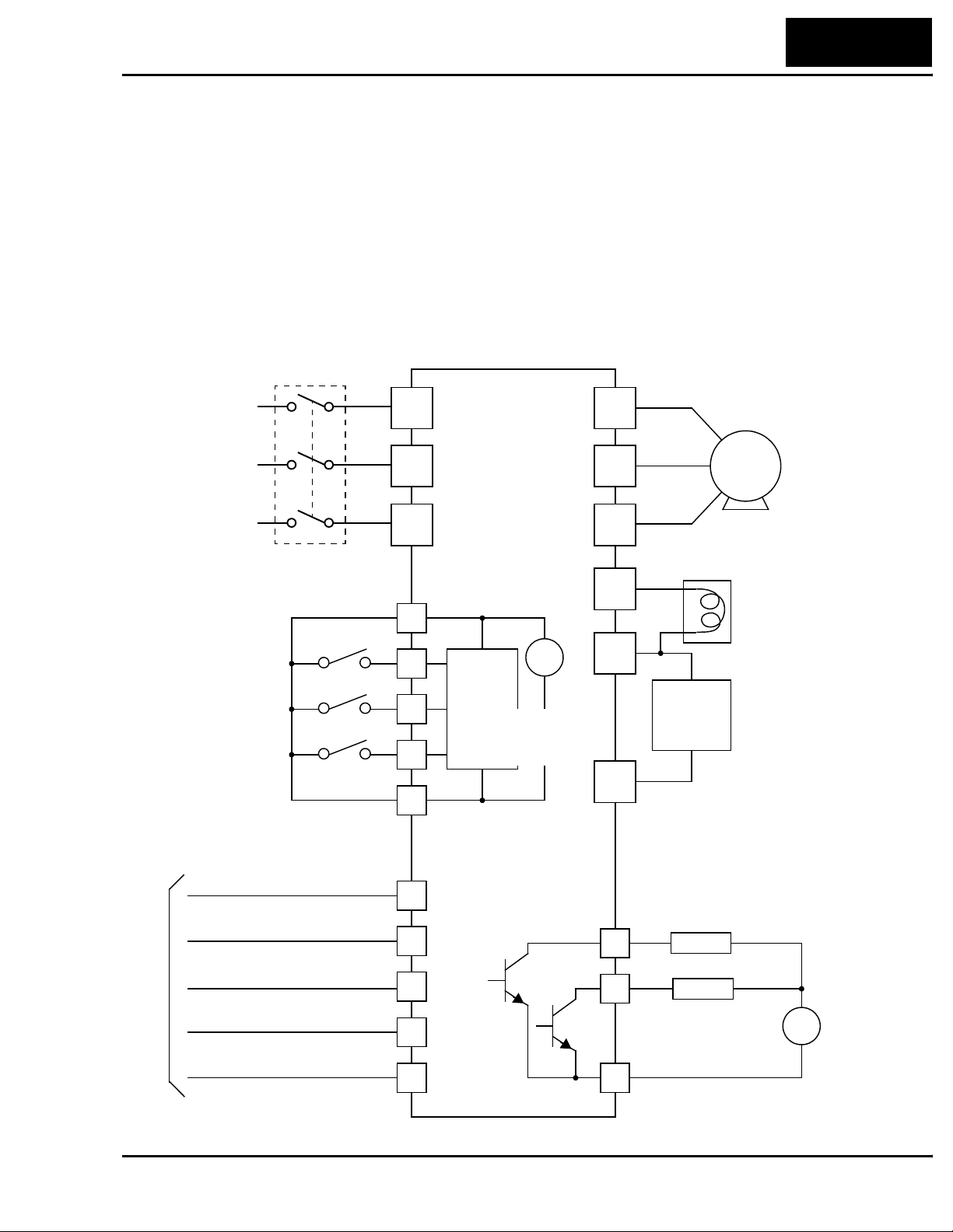
Example Wiring Diagram
The L100DN DeviceNet Series inverters have fewer intelligent I/O terminals and are
without analog I/O and relay outputs, in comparison to the standard L100 inverters. An
example wiring diagram for L100DN is shown below. The DeviceNet interface wiring is
discussed in detail in “Step 2 – Connect Network Devices” on page 43.
Breaker,
MCCB or GFI
L100DN
Power source,
3-phase or
1-phase, per
inverter model
R
(L1)
S
(L2)
U
(T1)
V
(T2)
L100DN Inverter
31
Motor
Intelligent inputs,
NOTE: For the wiring of intelligent I/O,
be sure to use
twisted pair /
shielded cable.
Attach the shield wire
for each signal to its
respective common
terminal at the
inverter end only.
Logic input common
DeviceNet interface
Bus supply +
CANbus High
Drain
CANbus Low
3 terminals
[FW]
[STP]
[EXT]
(Red)
(White)
(Bare)
(Blue)
T
N(L3)
P24
1
2
3
L
V+
CH
D
CL
24V
+
Input
circuits
[3] configurable
discrete inputs
–
Output
circuits
W
(T3)
+1
+
Braking
unit
(optional)
–
Open collector outputs
Run signal
12
11
Load
Alarm signal
Load
DC reactor
(optional)
+
–
Bus supply –
(Black)
V–
Logic output common
CM2
Page 32

32
Operations and Monitoring
Specifications of Control and Logic Connections
The control logic connector is located on the front panel, just below the keypad. The
color-coded DeviceNet connector is located directly below the logic connector. Connector labeling is shown below.
Logic inputs Logic outputs
L 3 12
Specifications for the logic connection terminals are in the following table:
Terminal Name Description Ratings
[P24] +24VDC for logic inputs 24VDC, 30 mA max
[1], [2], [3] Discrete logic inputs 27VDC max. (use P24 or an external supply refer-
[L] GND for logic inputs Sum of input 1, 2, and 3 currents (return)
[11], [12] Discrete logic outputs 50mA maximum ON state current,
[CM2] GND for logic outputs 100 mA: sum of 11 and 12 currents (return)
NOTE: The DeviceNet network must supply +24V to the inverter via the [V+] (Red)
and [V–] (Black) terminals on the DeviceNet connector. DO NOT attempt to use the
inverter’s internal 24VDC supply (on [P24] and [L]) for DeviceNet network power.
P24 CM2
12 11
DeviceNet network
connector
(Notes: Do not use for network power
Do not short to terminal L)
enced to terminal L)
(Note: Do not ground)
27 VDC maximum OFF state voltage
Auxiliary network
power connector
The DeviceNet connector signals must meet the electrical requirements given by the
DeviceNet industry standards. For more information, visit the Open DeviceNet Vendor
Association website at http://www.odva.org.
Page 33

Intelligent Input Summary
Intelligent input terminals for L100DN inverters include the standard L100 input terminals (see Chapter 3 in L100 Inverter Manual), with the following changes:
• Add [STA], [STP], and [F/R] terminals (three-wire interface inputs)
• Add [UP] and [DWN] remote control input terminals
• Add [DNT] terminal (DeviceNet Select)
• Add [OPE] Force Operation from Digital Operator input terminal
• Remove [AT] intelligent input terminals
The added terminals are described in the sections that follow.
Three-wire Interface Operation
The 3-wire interface is an industry standard motor control interface. This function uses
two inputs for momentary contact start/stop control, and a third for selecting forward or
reverse direction. To implement the 3-wire interface, assign 20 [STA] (Start), 21 [STP]
(Stop), and 22 [F/R] (Forward/Reverse) to the three intelligent input terminals. Use
momentary contact for Start and Stop. Use a selector switch such as SPST for the
Forward/Reverse input. Be sure to set the operation command selection A_02=01 for
input terminal control of motor. If you have a motor control interface that needs logiclevel control (rather than momentary pulse control), use the [FW] and [RV] inputs
instead.
L100DN Inverter
33
Option
Code
20 STA Start Motor ON Start motor rotation on momentary contact (uses
21 STP Stop Motor ON Stop motor rotation on momentary contact (uses
22 F/R FWD/REV ON Select reverse direction of rotation
Valid for inputs:
Required settings: A_02=01
Notes:
The [STP] input stops the motor, whether it is under
•
keypad control or under network control.
Terminal
Symbol
Function Name
C_01, C_02, C_03
Input
State
acceleration profile)
OFF No change to motor operation
deceleration profile)
OFF No change to motor operation
OFF Select forward direction of rotation
Example (requires input configuration—
see Chapter 3 in L100 Instruction Manual):
Description
STP
F/R STA
123L
P24
• [STP] is assigned to terminal [2} as a factory
default setting. This feature is especially important
for network-controlled applications.
• If you do not assign the [F/R] intelligent input
terminal, the three-wire operation will be limited to
the forward direction only.
See I/O specs in the L100 Instruction Manual
Page 34
34
Operations and Monitoring
Standard 3-wire control – By default, the
L100DN inverter comes with [STP] (Stop
Motor) assigned to terminal [2]. The Stop
command causes the motor to decelerate to
a stop when the inverter is in Run Mode.
Example (default input configuration shown—
see Chapter 3 in L100 Instruction Manual):
STP
123L
P24
When the inverter is controlled via keypad,
an operator will normally use the Stop/
Reset key on the front panel.
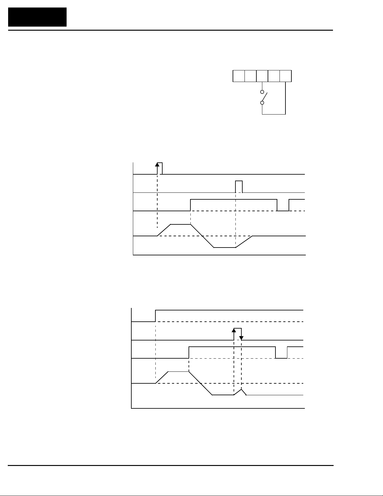
The diagram below shows the use of 3-wire control. STA (Start Motor) is an edge-sensitive input; an OFF-to-ON transition gives the Start command. The control of direction is
level-sensitive, and the direction may be changed at any time. STP (Stop Motor) is also a
level-sensitive input, and the Stop signal has priority over the Start signal.
STA
STP
F/R
Output
Frequency
t
When both STA and STP signals are ON, the STP signal has priority (motor output will
be OFF). However, the motor output resumes after STP signal is no longer active if the
STA input is still ON.
STA
STP
F/R
Output
Frequency
t
Page 35

L100DN Inverter
Use with DeviceNet operation – When the L100DN inverter is under network control,
Run and Stop commands will typically arrive via the DeviceNet network. However, a
network communications interruption is possible at any time. So for safety reasons, it is
important to provide a dedicated Stop signal input as shown below.
InverterNetwork host
[STP]
Run/Stop commands
DeviceNet network
In the graph below, the network FWD command places the inverter in Run mode. While
the motor is running, the local [STP] input terminal activates, causing the inverter to
decelerate the motor to a stop. It remains stopped even though the FW command is still
active. The FW command must turn OFF and ON again to resume motor operation.
35
Output
Frequency
Network FW command
[STP]
t
Page 36

36
Operations and Monitoring
DeviceNet Select
You can configure an intelligent input as [DNT] DeviceNet Select. It is not necessary to
assign an input terminal as [DNT] in order to control or monitor the inverter via the
DeviceNet network. Rather, the [DNT] input provides a way for an external control
system to selectively force the inverter to ignore DeviceNet commands and use only its
internal parameters and intelligent inputs for operation.
DeviceNet Control parameter P_43, DeviceNet Enable, serves a similar function—but it
is typically updated via the DeviceNet network. These two methods control essentially
the same thing, so it not meaningful to use both P_43 DeviceNet Enable and a [DNT]
input at the same time. If [DNT] is assigned to an input terminal, parameter P_43 is
ignored.
Option
Code
25 DNT DeviceNet Select ON The inverter operates per commands and param-
Valid for inputs:
Required settings:
Notes:
•
When any input terminal is assigned as [DNT],
parameter P_43 setting is ignored.
Terminal
Symbol
Function Name State Description
eters (output freq., accel, decel) from DeviceNet
OFF The inverter operates per local commands
(keypad or terminal Run/Stop) and its internal
parameters (speed, accel, decel).
C_01, C_02, C_03
Example (requires input configuration—
see Chapter 3 in L100 Instruction Manual):
DNT
123L
P24
• When [DNT] is OFF, the inverter is not under
control from DeviceNet commands. However, the
DeviceNet host computer can still monitor inverter
data via polled I/O, and it can still use Explicit
Messaging to individually change inverter parameters.
See I/O specs in the L100 Instruction Manual
• If you do not assign an input terminal as [DNT],
then parameter P_43 DeviceNet Enable is the sole
method of enabling/disabling control via the
DeviceNet network.
For more information on DeviceNet network configuration, see “Step 2 – Connect
Network Devices” on page 43.
Page 37

Remote Control Up and Down Functions
The [UP] [DWN] terminal functions can adjust the output frequency for remote control
while the motor is running. The acceleration time and deceleration time used with this
function is the same as for normal operation ACC1 and DEC1. The input terminals
operate as follows:
• Acceleration - When the [UP] contact is turned ON, the output frequency accelerates
from the current value. When it is turned OFF, the output frequency maintains its
current value.
• Deceleration - When the [DWN] contact is turned ON, the output frequency decelerates from the current value. When it is turned OFF, the output frequency maintains its
current value.
In the graph below, the [UP] and [DWN] terminals activate while the Run command
remains ON. The output frequency responds to the [UP] and [DWN] commands.
Output
Frequency
[UP]
L100DN Inverter
37
[DWN]
[FW] or [RV]
Option
Code
27 UP Remote Control
28 DWN Remote Control
Valid for inputs:
Required settings:
Terminal
Symbol
Function Name
UP Function
DOWN Function
C_01, C_02, C_03
Input
State
ON Accelerates (increases output frequency) motor
OFF Output to motor operates normally
ON Decelerates (decreases output frequency) motor
OFF Output to motor operates normally
Notes:
The availability of this feature does not depend on
•
A_01 (does not exist for DN Series models).
• This function is not available when [JG] is in use.
• The range of output frequency is 0 Hz to the value
in A_04 (maximum frequency setting).
• The Remote Control Up/Down function varies the
inverter speed by directly writing to the F_01
output frequency setting.
t
Description
from current frequency
from current frequency
Example (requires input configuration—
see Chapter 3 in L100 Instruction Manual):
UPDWN
123L
P24
See I/O specs in the L100 Instruction Manual
Page 38

38
Operations and Monitoring
Force Operation from Digital Operator
This function permits a digital operator interface to override the Run command source
setting (A_02) when it is configured for a source other than the operator interface. When
the [OPE] terminal is ON and the operator interface gives a Run command, the inverter
uses the standard output frequency settings to operate the motor.
Option
Code
31 OPE Force Operation
Valid for inputs:
Required settings:
Terminal
Symbol
Function Name State Description
ON Forces the operator interface Run command to
from Digital
Operator
OFF Run command operates normally, as configured
C_01, C_02, C_03
A_02=01
Notes:
When the [OPE] signal is ON, the keypad Run and
•
Stop keys are active, and [FW] or [RV] signal is
ignored. However, [OPE] cannot cause the keypad
to over-ride the DeviceNet host commands. To
enable/disable DeviceNet control via an input
terminal, use [DNT] (DeviceNet select).
• When changing the [OPE] state during Run Mode
(inverter is driving the motor), the inverter will stop
the motor before the new [OPE] state takes effect.
• If the [OPE] input turns ON and the digital operator
gives a Run command while the inverter is already
running, the inverter stops the motor. Then the
digital operator can control the motor.
over-ride commands from input terminals (such
as [FW], [RV])
by A_02
Example (requires input configuration—
see Chapter 3 in L100 Instruction Manual):
OPE
123L
P24
See I/O specs in the L100 Instruction Manual
Intelligent Output Summary
Intelligent output terminals for L100DN inverters include the standard L100 output
terminals (see Chapter 3 in L100 Inverter Manual), with the following changes:
• Remove [OD] (Output deviation for PID control) intelligent output terminal
Page 39

Network Control and Monitoring
DeviceNet Overview
DeviceNet is a communications network typically used in factory automation applications. It is a specific implementation of a Controller Area Network (CAN), first developed for the automotive market. IC manufacturers produce CAN ICs by the millions, so
they are low-cost and reliable. DeviceNet adapts this technology for industrial control. It
allows a programmable logic controller (PLC) or other host computer to control up to 63
field devices such as relays, solenoids, and motor drives such as Hitachi’s DN Series
inverters. DeviceNet has several advantages which have helped make it a popular choice
for various applications. The advantages include:
• Physical layout – main trunk line with individual drop lines
• Reduced wiring costs – uses a 5-wire cable; communications and device power are in
the same cable (power devices such as motor drives still require a main power source)
• Devices may be connected or disconnected without powering down the network (if
daisy-chained)
• Flexible device definitions – the device protocol provides for many types of input and
output structures
L100DN Inverter
39
• Open standard – allows multiple vendors to produce many types of products that can
coexist on a network
Slave Slave SlaveMaster
(PLC or host
computer)
DeviceNet is an open network standard, meaning that it has a non-proprietary protocol
and no licensing requirements. Hundreds of vendors are members of the Open
DeviceNet Vendor Association (ODVA), who ensures the integrity of the technical
standards and oversees device conformance testing. Hitachi DN Series inverters are
listed with the ODVA. This ensure compatibility with a wide range of devices from
vendors making thousands of DeviceNet compatible industrial products. This also helps
to connect those same devices over long distances in the factory.
Slave (up to 63
Slaves)
Page 40

40
Network Control and Monitoring
Inverter Networking Overview
The L100DN DeviceNet Series inverters can operate under local control (via operator
input via the keypad or via input terminal signals). This control method was covered in
the previous section, “Operations and Monitoring,” and also in the L100 inverter
manual’s Chapter 4, also named “Operations and Monitoring.”
The “Network Control and Monitoring” section will first show you how to connect the
inverter to a DeviceNet network. Next, you will learn how to monitor and control the
inverter from the network master (host computer). These instructions are presented in a
series of steps, with each one preparing your application for the next one. Therefore, be
sure not to skip any steps in this section.
NOTE: Be sure to install the inverter and perform the powerup test described in the
“Inverter Mounting and Installation” on page 9 before attempting network operation.
The step to DeviceNet network control and monitoring are:
1. Design your network layout
2. Connect network devices
a. Add network termination
b. Add network power
3. Prepare network host computer
4. Prepare inverter for network
5. Understand the inverter’s I/O structure
a. Polled I/O
b. Explicit messaging
6. Monitor test – verify network host can monitor inverter
7. Control test – verify network host can control inverter
8. Use DeviceNet Explicit Messaging
9. Create a host computer control program
Note that the test to monitor the inverter from the network occurs before the test to
control the inverter via the network. The setup for monitoring is more simple, and helps
prepare the devices for the control step.
Page 41

Step 1 – Design Your DeviceNet Network Layout
Your DeviceNet network layout will be determined by several factors, including the
physical machine or plant layout. The network must have one network master, or host
computer such as a PLC or control PC. The L100DN Series inverter is a DeviceNet
slave. The network can have up to 63 slaves which can include inverter(s), sensors,
actuators, or other intelligent devices.
Master
Slave Slave
(network host)
Slave
L100DN Inverter
41
(up to 63
Slaves)
Addr=12Addr=04Addr=29 Addr=44
Addr=63
(default)
The network diagram above shows a network master (host computer), and four slave
devices. Each device constitutes a “node,” and each node must have a unique address.
The address is also called the MAC ID (Media Access Control Identification). As shown
in the diagram, the node addresses do not have to occur in a particular sequence in the
physical layout.
Showing node connections now in greater detail, the connection to each device in the
middle of the network may be a daisy-chain connection or a drop connection. The differ-
ence is that a daisy-chain connection enters and exits right at the connector, while a drop
connection inserts an extra segment just for the device. The device at each end of the
physical network must include a termination resistor. The host computer and the inverter
may be in the middle or at the ends of the network.
Drop
line
Daisy-
chain
Trunkline
Daisy-
chain
TerminationTermination Ta p
Page 42
42
Network Control and Monitoring
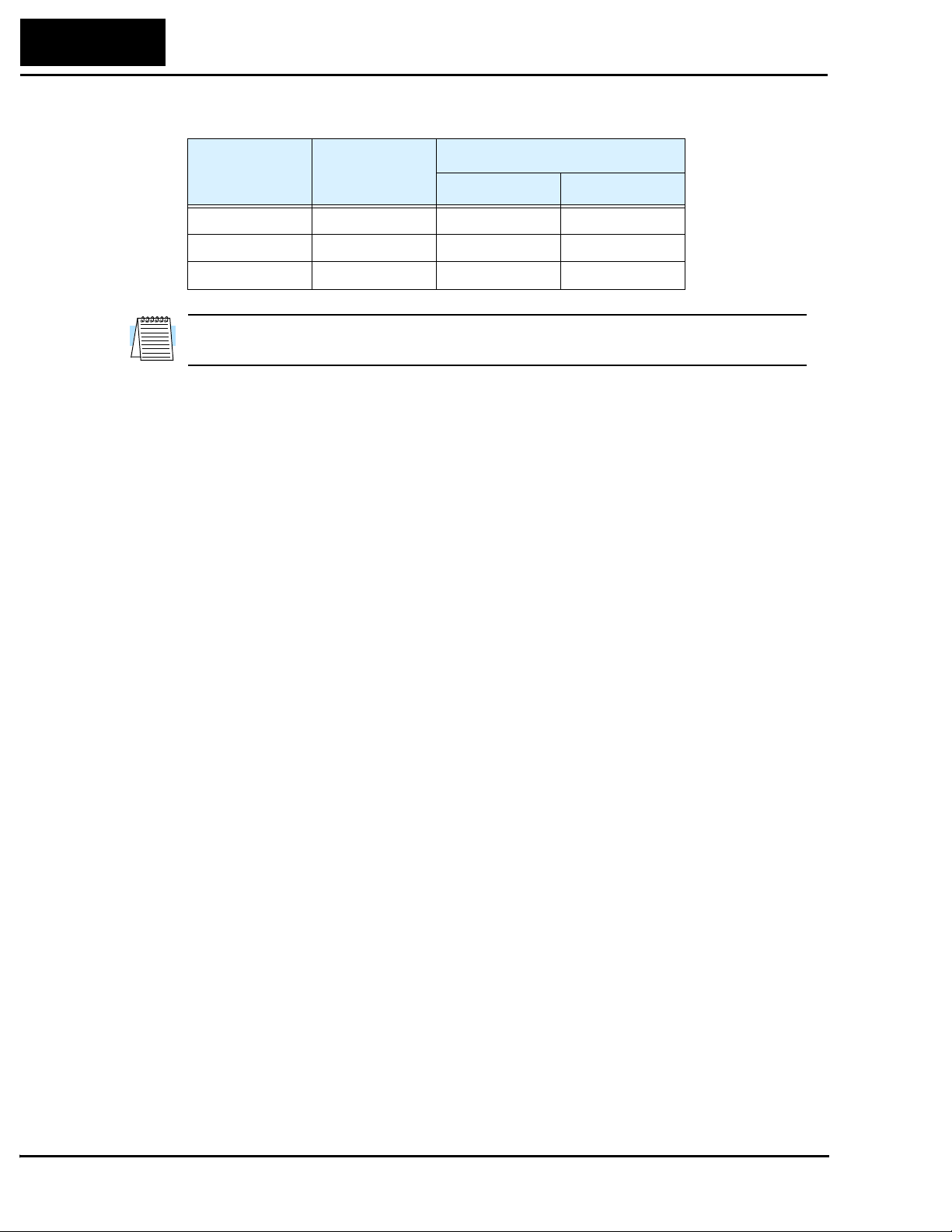
DeviceNet networks support three baud rates, listed in the following table.
Baud Rate
125 kbps 500m (1640 ft.) 6m (20 ft.) 156m (512 ft.)
250 kbps 250m (820 ft.) 6m (20 ft.) 78m (256 ft.)
500 kbps 100m (328 ft.) 6m (20 ft.) 39m (128 ft.)
NOTE: If thin cable is used for the trunk line, the maximum distance is 100m (for all
baud rates).
Trunk length
(thick cable)
Maximum Cumulative
Drop Length
Page 43

Step 2 – Connect Network Devices
A DeviceNet node connects to the network with five electrical connections. The diagram
below shows the inverter connection as an example. The cable uses two twisted pairs
with a shield. One twisted pair is for data, and the other is for +24V power. The color
code shown is standard for DeviceNet.
DeviceNet Connection
DeviceNet interface
L 3 12
L100DN Inverter
P24 CM2
12 11
43
Bus supply +
CANbus High
Drain
CANbus Low
Bus supply –
The diagram below shows L100DN inverters connected to a DeviceNet network. Each
connection is called a node, and the L100DN connects to the network via the 5-pin,
color-coded Phoenix connector on the front panel as shown.
Add network termination – A termination resistor (121Ω nominal) is required at each
physical end of a DeviceNet network (segment) as shown in the diagram below. Each
device does not typically have an internal termination resistor, as several such devices
together would overload a network. The terminations provides signal integrity and noise
immunity. Therefore, add two resistors as close to the endpoint connectors as possible.
DeviceNet Terminations
Device at end of network
(Red)
(White)
(Bare)
(Blue)
(Black)
L 3 12
P24 CM2
12 11
Bus supply +
CANbus High
Drain
CANbus Low
Bus supply –
TIP: To simplify configuration and startup, we recommend starting with just the
network host (PLC or computer) and the inverter. It is easier to resolve addressing or
other conflicts with fewer devices. With network wiring for just two devices, you will
need a termination resistor at both devices. After establishing network communications
with the inverter, you can add other devices individually with a minimum of problems.
Remember to maintain network termination at the endpoints at all times.
121Ω121Ω
Page 44

44
Network Control and Monitoring
Add network power – Many devices such as sensors and relays can be powered directly
from the network. However, inverters generally use much more power and a higher input
voltage than a network could provide. As demonstrated by the installation powerup test,
L100DN Series inverters need only the AC input power for stand-alone operation. For
network monitoring or control, you must also supply external +24V network power to
the DeviceNet connector. The inverter has internal optical isolation from the network,
and draws negligible network power as a result. DeviceNet specifications support up to
8A per network segment.
NOTE: Class II NEC Code limits the current for any network segment to 4A. DeviceNet
thick type cable is limited to 8A; thin type cable is limited to 3A.
Add a +24VDC supply to the network as shown below. It is not necessary to power it for
this step; later steps will provide powerup instructions..
DeviceNet Supply
24VDC
+–
Alternatively, you can use the auxiliary network power connector as shown below (left).
The inverter internally connects the two connectors to pass through network power.
Bus supply +
CANbus High
Drain
CANbus Low
Bus supply –
(Red)
(White)
(Bare)
(Blue)
(Black)
L 3 12
P24 CM2
12 11
Internal
connections
Bus supply +
Auxiliary network
power connector
L 3 12
DeviceNet network
Bus supply –
P24 CM2
connector
12 11
Page 45

L100DN Inverter
The example wiring diagram below shows the auxiliary network power connector being
used for the network power supply connection.
Inverter
45
Auxiliary network
power connector
+–
24VDC
DeviceNet
Supply
DeviceNet network
connector
L 3 12
P24 CM2
12 11
Bus supply +
CANbus High
Drain
CANbus Low
Bus supply –
(Red)
(White)
(Bare)
(Blue)
(Black)
Using the auxiliary network power connector provides flexibility and convenience in
wiring your application. Be sure to read the following points to avoid any problems:
• Make sure the polarity of the power supply connection is correct. If in doubt, check
continuity between the two connectors to ensure the polarity is maintained.
• The power supply must provide proper output current limit and fusing for the network
device load.
• Remember that you must open the front door panel of the inverter to connect or
disconnect wiring to the auxiliary network power connector. If power has been
connected, wait five minutes after powerdown and verify the Power LED is OFF
before opening the inverter front door panel.
Page 46
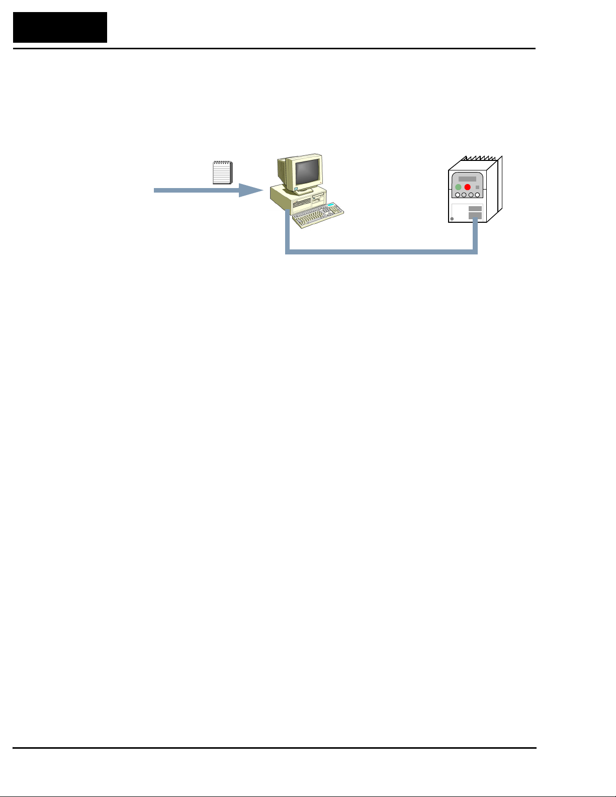
46
Network Control and Monitoring
Step 3 – Prepare Network Host Computer for Network
This step presumes that you have already connected your network host device (PLC or
computer) to the DeviceNet network. If using a PC, the addition of a DeviceNet scanner
card is usually required.
EDS file
InverterMaster (network host)
Addr=?
(you select)
Load EDS file – The I/O structure of smart field devices such as inverters are unique.
Consequently, you must provide a network host computer with the I/O image of smart
devices on the network. DeviceNet standards provide for a quick way to equip host
computers with device-specific I/O images. The data is contained in an EDS file
(Electronic Data Sheet). Manufacturers develop EDS files for their DeviceNetcompatible products, providing them to the DeviceNet standards organization. The
ODVA (Open DeviceNet Vendors Association) maintains the files for download. Do the
following steps:
• Visit the website at http://www.odva.org
• Navigate to the Downloads area, and then to EDS files.
• From the EDS files, select “Hitachi” as the manufacturer.
• Download the file that matches your inverter’s version (L100DN2, for example)
• Then load or place the EDS file in your network host device in the location (directory)
it requires for use in network device scanning. Refer to the documentation of your host
device for this information.
Set node address of host – If you have not already done so, set the node address (the
MAC ID). It must be different from the inverter’s node address. Refer to the documentation of your host device for the address setting procedure. We recommend not using
“00,” since that is the default of many other devices.
Addr=63
(default)
Set baud rate of host – The host computer’s baud rate and the inverter’s baud rate must
match in order for them to communicate. We recommend using the lowest baud rate
(125 kbaud) to get the network up and running. The default baud rate of the inverter is
125 kbaud.
Page 47

Step 4 – Prepare Inverter for Network
Verify that the inverter’s DeviceNet parameters are set as directed.
• P_41 baud rate setting must be the same as your network host computer.
• P_42 MAC ID setting must be different from your network host computer.
• P_43 DeviceNet enable must be set = 1 (required by subsequent steps in example).
• P_44 and P_45 are recommended to remain at the default settings.
• P_46 and P_47 must be set to the default values (required by subsequent steps).
• P 48 selects the inverter’s action if the inverter detects network idle (leave at default).
• P 49 allows the host computer to command motor in output freq. (set = 0) or by motor
speed in RPM (set = to number of poles). Leave at default (set = 0) for this example.
“P” Function
Func.
Code
Name Description
L100DN Inverter
47
Defaults
P_41 DeviceNet baud rate Three options; select codes:
00 ... 125 kbps
01 ... 250 kbps
02 ... 500 kbps
P_42 DeviceNet MAC ID Selects the DeviceNet node
address, range is 0 to 63
P_43 DeviceNet control enable Two options; select codes:
00 ... Disable
01 ... Enable
P_44 DeviceNet comm watchdog timer Range is 0.00 to 99.99 seconds
P_45 Inverter action on DeviceNet comm
error
P_46 DeviceNet polled I/O: Output instance
number
P_47 DeviceNet polled I/O: Input instance
number
P_48 Inverter action on DeviceNet idle mode Five options:
Five options:
00 ... Trip
01 ... Decelerate and trip
02 ... Hold last speed
03 ... Free-run stop
04 ... Decelerate and stop
Three settings:
20, 21, 100
Three settings:
70, 71, 101
00 ... Trip
01 ... Decelerate and trip
02 ... Hold last speed
03 ... Free-run stop
04 ... Decelerate and stop
00
63
01
1.00
01
100
101
01
P_49 DeviceNet motor poles setting for RPM Range is 00 to 38 (even
numbers only), two types:
00 ... For freq. setting (Hz)
02 to 38... For speed (RPM)
00
Page 48

48
Network Control and Monitoring
Step 5 – Understand the Inverter’s I/O Structure
In DeviceNet terminology, I/O devices can either produce or consume data. An input
point (or data byte or word) produces data, while an output point (or data byte or word)
consumes data. The DeviceNet standard also provides for various ways the network
master accesses I/O, either more or less frequently, according to certain criteria. The
main benefit of having this variety is to let you conserve network bandwidth by using it
where the application most needs it. DeviceNet categorizes I/O communication
exchanges into several types listed below.
Polled I/O (supported in L100DN) – The Poll command initiated by the master
contains output data. When the slave (inverter) is polled, it automatically returns input
data to the master, which also serves as an acknowledgement. The main advantage of
Polled I/O is that a fixed (predetermined) set of I/O data can be exchanged upon each
network scan. There is no need to specify each bit or word of the request for output and
input. The Run/Stop commands and output frequency command are included in the
polled I/O set for the inverter.
Bit Strobe, Cyclic, and Change-of-State (not supported in L100DN) – These master
commands are oriented to simpler I/O devices, time-based updates, or value-change
updates. More suited to simple or analog applications such as data logging, these
network master commands are not supported by L100DN inverters.
Explicit Messaging (supported in L100DN) – The Explicit Messaging mechanism
goes beyond the four standard scan mechanisms listed above. A master can use an
Explicit Message request to Get (read) or Set (write) specific data in a device such as the
inverter. In that specific request, the master provides the complete network address to the
device and the register within that device. The inverter has many parameters, but most of
them need accessed rarely via the network. Thus, the inverter supports explicit messaging access to all of its parameter values.
The timing diagram below shows a simplified network activity timing diagram. The poll
command and response occur at the regular interval of the master’s scan time. This
represents the polled I/O data (includes Run/Stop commands, inverter’s output frequency
and accel / decel times). One explicit message event occurs in the available “quiet” time
within the network activity. This represents the master doing a single access of a specific
inverter parameter (suited for rarely accessed parameters such as torque boost, etc.).
Poll & response
Scan time
Network activity
Explicit message & response
t
Page 49
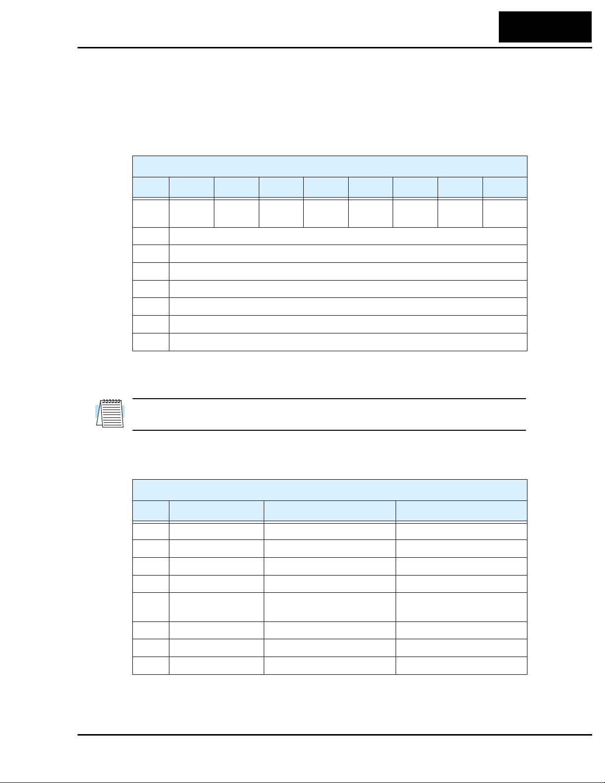
L100DN Inverter
Polled I/O Data Map, Inverter Outputs – The polled I/O for the inverter maps to four
words (16 bits each) input data, and four words output data. This represents a small
portion of the inverter’s parameters and commands—just those required to manage
motor operation in real time. Some data words contain discrete (individual) bits (used as
flags), while others words contain values (used as scalar numbers). When the network is
active, polled I/O data is automatically updated on each network scan.
Inverter Produced Data, (Host) Input Instance (P_47) = 101
Byte Bit 7 Bit 6 Bit 5 Bit 4 Bit 3 Bit 2 Bit 1 Bit 0
49
0 Input
term. [3]
1 Inverter status (see status code table, next page)
2 Output frequency monitor (low byte), D_01 value
3 Output frequency monitor (high byte), D_01 value
4 Output current monitor (low byte), D_02 value
5 Output current monitor (high byte), D_02 value
6 Trip error code, D_08 value
7—
Input
term. [2]
Input
term. [1]
Freq.
Arrival
— Trip RV Run FW Run
The I/O image above corresponds to the default (Host) Input Instance P_47 = 101. The
Inverter Consumed Data, (Host) Output Instance I/O image is presented in Step 7.
NOTE: P_47 = 70 and P_47 = 71 settings provide other produced data configurations
(not used in this example). See “Polled I/O Configurations” on page 66.
The following table defines individual bits of the status byte.
Inverter Produced Data, Status Byte
Bit Name Bit = 0 Bit = 1
0 FW Run Inverter stopped or in RV Inverter in FW Run
1 RV Run Inverter stopped or in FW Inverter in RV Run
2 Trip No faults exist Trip exists, not cleared
3— — —
4 Frequency arrival Inverter stopped, or in accel or
decel
5 Input terminal [1] Input [1] = OFF Input [1] = ON
6 Input terminal [2] Input [2] = OFF Input [2] = ON
7 Input terminal [3] Input [3] = OFF Input [3] = ON
Inverter output arrived at
target freq.
Page 50

50
Network Control and Monitoring
The inverter state is represented by a code number in byte 1 of the produced (output)
data. The following table lists the code values (decimal) and their meanings.
Inverter Produced Data, Inverter State Code Byte
Code
(dec.)
0 The inverter is Stop Mode.
1 The inverter is in Run Mode.
2 The inverter is in Jog Mode.
3 The inverter is in Stop Mode and the motor output is free running (coasting).
4 The inverter is executing DC braking (includes CD braking wait time).
5 The inverter is attempting a restart with frequency matching (B_01 = 03).
6 The output is stopped for an instantaneous power failure.
7 The inverter is attempting a restart with frequency matching (B_01 = 02).
8 The inverter is waiting before it attempts a restart with frequency matching. The wait
time is set by parameter B_03.
9 The inverter is in a trip condition, and is storing the trip history data to EEPROM. A
Stop/Reset command to clear the trip is ignored in this state.
10 The inverter is in a trip condition.
11 An under-voltage condition exists at the inverter power input.
Description
TIP: The next step (Step 6) verifies that the network host can monitor the inverter. The
network host will monitor the inverter’s produced (output) data while the motor is
running. The step shows how to monitor and interpret produced data while the motor is
running in a typical application.
Page 51

L100DN Inverter
Step 6 – Monitor Test – Verify Network Host Can Monitor Inverter
This step requires that you have completed the previous 5 steps, and that the powerup
test during the installation was successful (see “Running the Motor” on page 24). At this
point in the procedure, the inverter is using front panel keypad inputs for Run/Stop
commands. The DeviceNet host computer can monitor inverter operation without
actually controlling the inverter. So, you do not have to change any “P Group” parameters from their defaults to do this network monitoring test.
Inverter Status LEDs – The two status LEDs on the
inverter’s front panel are to the right of the Stop key.
• MS – Module Status
• NS – Network Status
RUN
PRG
HITACHI
50.0
51
POWER
Hz
A
The status LEDs may be green or red, and may or OFF,
RUN
STOP
RESET
ON, or flashing between OFF and ON. The table below
shows how to interpret the status LED indications. (At
FUNC.
2
1
this point, the correct status is MS=green, NS=OFF.)
LED Color Status Corrective Action
MS Green Normal power-ON status —
Flashing Green Inverter in standby state —
Red Fatal error (trip E11 or E12)
• Confirm electrical noise level
is acceptable
• Replace inverter
Flashing Red Trip condition (non-fatal) Look up error code in manual
Chapter 6, press Stop/Reset
OFF Inverter power is OFF —
NS Green Connected to network/online —
Flashing Green Connected to network/idle —
Red Critical network error Check network for:
• Disconnected cable
• Termination resistor not
present / wrong value
• Duplicate MAC IDs
• Baud rate settings mis-match
• Cable too long
STR
MS
NS
Flashing Red Communications time-out Check network for:
• Disconnected cable
• Termination resistor not
present / wrong value
• Baud rate settings mis-match
• Cable too long
OFF Power OFF or DeviceNet offline —
Page 52
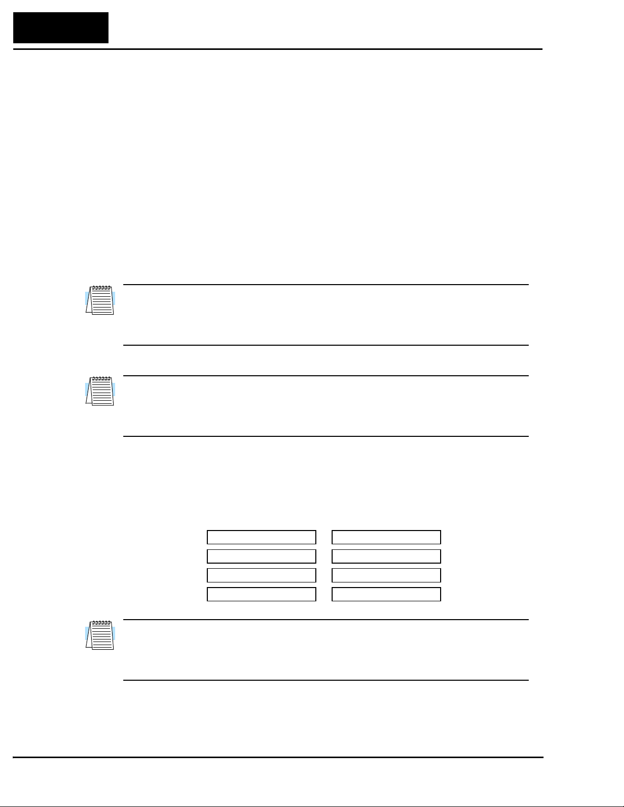
52
Network Control and Monitoring
Inverter Monitoring Sequence – Follow these steps to monitor inverter operation via
the DeviceNet network. In this sequence, you will control the inverter from its keypad,
but monitor operation from the network host computer.
a. Begin with power off to the network host, the inverter, and the network power.
b. Turn ON the +24VDC network power.
c. Turn ON power to the host computer and the inverter. The status LEDs will
indicate: MS LED = Green, and the NS LED = OFF.
d. Confirm that the Run Key Enable LED is ON. It is directly above the Run key. If
it is OFF, then be sure that A_02 = 02.
e. On the host computer, start the application that connects it to the network.
f. Set the host application to scan the DeviceNet network. (Do any configuration
required to let the host “see” the inverter on the network.) You may notice that the
inverter’s NS LED = Flashing Green during network startup.
NOTE: If the inverter detects another device on the network has the same MAC ID, the
inverter will display the MAC ID code on the front panel display and the inverter is in
Stop Mode. When in Run Mode (or after any key is pressed), the display reverts to the
normal indications.
g. Verify that the inverter’s MS LED = Green, and now the NS LED = Green.
NOTE: If the NS LED = OFF, the network is disconnected. Check the cable, and also
check the host application software settings. If the NS LED = Flashing Green, the
network is connected, but idle. Start the host network scan to cause NS LED = Green. If
Red or Flashing Red, use the Status LED table on the previous page to troubleshoot.
h. Confirm that the host computer can see the inverter’s polled I/O. You will be
monitoring the inverter’s produced (output) I/O data, which are inputs to the host
computer. At this point, all data words = 0000h as shown below.
Inverter Polled I/O
Produced (Output)
MSB LSB
Word 0
Word 1
Word 2
Word 3
High byte
0 000 0000
0
000 0000
0
000 0000
0
000 0000
Low byte
MSB LSB
0 000 0000
0
000 0000
0
000 0000
0
000 0000
Hex
0000h
0000h
0000h
0000h
Decimal
0
0
0
0
NOTE: If the host computer cannot find the inverter’s polled I/O data, then check the
host application software—its settings and configuration. Refer to the documentation
that came with the host computer software. You may also verify that the host computer
can communicate with another known working device (provided its MAC ID is unique).
i. Provided that the host computer finds the inverter’s produced I/O, press the Run
key on the inverter keypad. The motor should run in the same way it did for the
powerup test during the inverter installation.
Page 53

L100DN Inverter
j. With the inverter output ON and the motor rotating, now you can use the host
computer to monitor the inverter’s polled I/O. The following diagram shows the
expected (typical) data, using the default settings.
Inverter Polled I/O
Produced (Output)
MSB LSB
Word 0
High byte
000 0001
0
Low byte
MSB LSB
0
001 0001
Hex
0111h
53
Decimal
273
Word 1
Word 2
Word 3
000 0101
0
000 0000
0
0
000 0000
1
101 1100
0
000 1011
0
000 0000
05DCh
000Bh
0000h
1500
11
0
Using the Polled I/O Data Map for produced (output) data given in Step 5, you
can interpret the data sent to the host computer. For scalar values such as
frequency and current, a scale factor of 1, 10, 100, or 1000 applies. The “Network
Register Map” on page 78 lists the inverters parameters and the scale factor used
to get/set the parameter value over the network. To get a parameter’s actual value,
divide the value sent by the inverter (in decimal form) by the scale factor.
• Word 0 – The status bits that are set have the meanings indicated below:
High byte
MSB LSB
Word 0 0111h
0 000 0001 0001 0001
Inverter state = 1
(Run Mode)
MSB LSB
Freq. arrival FW Run
Low byte
Hex
Decimal
273
• Word 1 – The decimal value “1500” for output frequency corresponds to 15.00Hz
(D_01 reading) when the scale factor of 100 is applied. Recall that the powerup
test procedure for the installation set F_01 = 15.0Hz (restore this value if needed).
• Word 2 – The decimal value of “11” for output current corresponds to 1.1A (D_02
reading) when the scale factor of 10 is applied. This value represents a small
inverter and motor size; your reading may differ.
• Word 3 – The decimal value of “0” for trip code (D_08 reading) corresponds to
“no trip” status.
NOTE: When a trip event occurs, the polled I/O will indicate it by Trip Bit = 1 in
Word 0 and the actual Trip Code in Word 3. When the trip condition is cleared (Stop/
Reset key), then the Trip bit = 0, but the Trip Code in Word 3 remains. To clear it also,
you must clear the inverter’s trip history. For more information, see “Restoring Factory
Default Settings” on page 94.
k. Press the Stop/Reset key on the inverter. This will cause the motor to stop, and the
Polled I/O (produced data) shown above will return to 0 values.
l. To complete this monitoring sequence, stop the host computer’s DeviceNet scan.
Page 54

54
Network Control and Monitoring
Step 7 – Control Test – Verify Network Host Can Control Inverter
If your network host computer successfully monitored the inverter’s operation in Step 6,
then achieving control capability from the network host in this step will be easy. First, it
is important to know how to change inverter control between local (keypad) control and
network control. Then you will be ready to control the inverter from the network.
Parameter Changes and Network Errors – Note that changing “P Group” DeviceNet
parameter values in the inverter causes the inverter to reset and initialize its network
operations. If the DeviceNet host computer is scanning at that moment, the inverter will
cause a network time-out error when it initializes. So, you can avoid these network errors
by stopping the network scan activity before changing “P Group” parameter values.
Configuring for Network Control – The configuration for network control depends on
several factors. Understanding the principles below will help simplify how network
control works:
• “Local control” refers to the inverter accepting Run/Stop commands from either its
keypad or input terminals [FW] or [RV], if configured. “Network control” refers to a
host computer remotely sending Run/Stop commands via a DeviceNet connection.
• A DeviceNet setting or signal at the inverter enables or permits network control. This
means that an operator or control system at the inverter can, at any time, take back
control of the inverter from a network host by disabling DeviceNet control.
• The inverter uses P_43 DeviceNet Control Enable for the primary method of control
selection. By default, P_43 = 1 (set to enable network control).
• Alternatively, you can assign the intelligent input terminal [DNT] Select DeviceNet.
Its ON/OFF states work the same way as P_43 settings. Note that when [DNT] is
assigned to an input terminal, the inverter ignores the P_43 setting.
The table below summarizes these network control principles.
Configuring Network Control of Inverter
P_43 DeviceNet
No.
Control Enable
1 P_43 = 1, Enable
(default setting)
2 P_43 = 0,
Disable
3 — [DNT] = ON Same description as No. 1. (When [DNT] is
[DNT] Select
DeviceNet
(not assigned) Inverter control may be done via network polled
I/O. Inverter automatically resumes local control
if network host sets Network Control bit = OFF,
or the network scan or connection is lost.
(not assigned) The inverter ignores network polled I/O control.
However, the network host can still monitor the
inverter via polled I/O, and it can use explicit
messaging to get or set parameter values.
assigned, the inverter ignores P _43 setting.)
Control Method Description
4 — [DNT] = OFF Same description as No. 2. (When [DNT] is
assigned, the inverter ignores P _43 setting.)
Page 55

L100DN Inverter
When the inverter has enabled DeviceNet control via P_43 or a [DNT] terminal input
signal, the DeviceNet host may control the inverter. However, the host computer must
also set bit(s) in the polled I/O that is input data (consumed I/O) to the inverter. The bit
names and definitions are:
• Network Control – When the Network Control bit = 1, the host computer indicates
that it wants to control the inverter. If the inverter setting P_43 or [DNT] has enabled
control, then the host computer can give FW Run and RV Run commands.
• Network Reference – Independent of network control, the host computer can supply
the following parameter values for real-time motor control:
• Output frequency – An alternate source for F_01 Output Frequency Setting
• Acceleration time – An alternate source for F_02 Acceleration Time Setting
• Deceleration time – An alternate source for F_03 Deceleration Time Setting
When the Network Reference bit = 1, the host computer indicates that it wants to
supply the output frequency and accel/decel setting to the inverter. If the inverter
setting P_43 or [DNT] has enabled network control, the inverter will use the alternate
values via DeviceNet. This applies independently of the Network Control bit setting.
55
The table below describes the Network Control and Network Reference setting logic.
The logic requires that the inverter has enabled DeviceNet control as described above.
Network Control and Network Reference Bit Logic *1
No.
1 0 0 Inverter F_01, F_02, F_03
2 1 0 Network host F_01, F_02, F_03
3 1 1 Network host Polled I/O from host
4 0 1 Inverter Polled I/O from host
Network
Control bit
Network
Reference Bit
Source for Run/Stop
Source for Output
Freq. / Accel / Decel
Note 1: Logic above requires inverter’s P_43 or [DNT] to enable DeviceNet control.
Typically a network host computer needs to have control of Run/Stop, speed, accel, and
decel. This corresponds to No. 3 above, where both Network Control and Network
Reference bits are set = 1. If the inverter needs temporary local control, you can either:
• Turn OFF the Network Control bit and/or Network Reference bit at the network host.
Note that if you turn OFF only one of the two bits, the Run/Stop control comes from
one device and the speed / accel / decel values comes from the other device. Or,
• Use the inverter’s DeviceNet enable settings P_43 or the input terminal [DNT]
(whichever is in effect) to temporarily disable DeviceNet control. This will cause the
inverter to have local control of Run/Stop and the speed / accel / decel settings.
The DeviceNet network may remain online (scanning) without errors while changing the
control between local or network, or changing the speed / accel / decel source.
Page 56
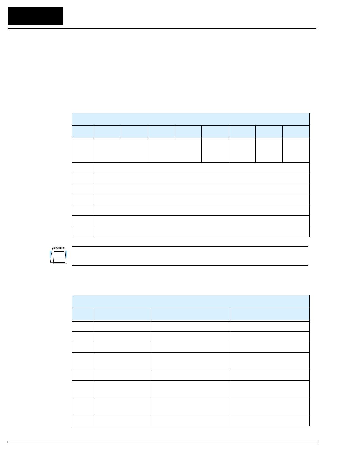
56
Network Control and Monitoring
Polled I/O Data Map, Inverter Inputs – The polled I/O for the inverter maps to four
words (16 bits each) input data, and four words output data. In this section, we are
concerned with the four words the host computer uses to control the inverter.
The following Polled I/O table shows how the host computer’s control bits and reference
data (output freq. / accel / decel) are organized. Word 0 (lower byte) contains discrete
(individual) bits (used as flags). Data words 1, 2, and 3 contain values (used as scalar
numbers). When the network is active, polled I/O data is automatically updated on each
network scan.
Inverter Consumed Data, (Host) Output Instance (P_46) = 100
Byte Bit 7 Bit 6 Bit 5 Bit 4 Bit 3 Bit 2 Bit 1 Bit 0
0 — Network
Refer-
ence
1—
2 Output frequency (low byte), host override for F_01 value
3 Output frequency (high byte), host override for F_01 value
4 Acceleration time (low byte), host override for F_02 value
5 Acceleration time (high byte), host override for F_02 value
6 Deceleration time (low byte), host override for F_03 value
7 Deceleration time (high byte), host override for F_03 value
Network
Control
— Free run
Stop
Fault
Reset
RV Run FW Ru n
NOTE: P_46 = 20 and P_46 = 21 settings provide additional consumed data configurations (not used in this example). See “Polled I/O Configurations” on page 66.
The following table defines individual bits of the control byte.
Inverter Consumed Data, Control Byte
Bit Name Bit = 0 Bit = 1
0 FW Run Stop FW Run command
1 RV Run Stop RV Run command
2 Fault Reset — Reset the inverter, clear trip
3 Free Run Stop — Cause motor to free run
(coast) and stop
4— — —
5 Network Control Run/Stop control is local to
inverter
6 Network Reference Output freq. / accel / decel is
from F_01, F_02, F_03
7— — —
Run/Stop control is from
network host polled I/O
Output freq. / accel / decel is
from network host polled I/O
Page 57

L100DN Inverter
Inverter Control Sequence 1 – In this first sequence, the DeviceNet host computer will
control the inverter (Run/Stop), but the inverter will use its internal parameters for output
frequency / accel / decel (F_01, F_02, and F_03). This sequence assumes that you have
successfully completed the Monitoring Sequence in Step 6.
a. Confirm that the DeviceNet network is online, and the host computer is scanning
the network.
b. Confirm that the Run Key Enable LED is still ON. It is directly above the Run
key. If it is OFF, then be sure to set A_02 = 02. (This sequence will not make use
of the Run key, but it will ask you to observe the Run Key Enable LED.)
c. Confirm that the motor is stopped.
d. Refer to the control byte in Word 0 as shown below. With the host computer, set
the Network Control bit (bit 5) = 1. As you do this, notice that the Run Key
Enable LED on the inverter turns OFF. This indicates that the inverter has
switched its control source from local to network control.
Inverter Polled I/O
Consumed (Input)
MSB LSB
Word 0 0020h
High byte
Low byte
MSB LSB
0
010 00000 000 0000
Hex
Decimal
32
57
Network Control FW Run
e. Turn ON the FW Run bit (bit 0) in Word 0 as shown below. The motor will now
begin to run. The output frequency will be 15.00Hz (set by F_01). To verify the
motor speed, monitor D_01 on the inverter display, or use the host computer to
observe the actual output frequency reported in the polled I/O.
High byte
MSB LSB
Word 0 0021h
Network Control FW Run
MSB LSB
0 010 00010 000 0000
Low byte
Hex
Decimal
33
f. Now turn OFF the FW Run bit (bit 0) in Word 0 as shown below. The motor will
now stop.
High byte
MSB LSB
Word 0 0020h
Network Control FW Run
MSB LSB
0 010 00000 000 0000
Low byte
Hex
Decimal
32
The first control sequence is complete. The host computer controlled the inverter with
Run/Stop, allowing the inverter to use its own profile parameters (F_01, F_02, F_03).
Page 58

58
Network Control and Monitoring
Inverter Control Sequence 2 – In this second sequence, the DeviceNet host computer
will control the inverter (Run/Stop) and also provide values for output frequency / accel /
decel (overrides F_01, F_02, and F_03). This sequence assumes that you have successfully completed Control Sequence 1 on the previous page.
a. Confirm that the motor is stopped.
b. Turn ON the Network Reference bit (bit 6) in Word 0 as shown below. This
indicates to the inverter that the network will supply real-time profile values for
output frequency / accel / decel. (The Network Control bit should still be ON.)
DO NOT turn on the FW Run bit (bit 0) yet.
Inverter Polled I/O
Consumed (Input)
MSB LSB
Word 0 0060h
High byte
Network Reference
Network Control FW Run
Low byte
MSB LSB
110 00000 000 0000
0
Hex96Decimal
c. Refer to the values for Word 1, Word 2, and Word 3 listed below. With the host
computer, set the values as indicated.
Word 1 (Output Frequency) = 2000 decimal (20.00Hz)
Word 2 (Acceleration time) = 100 decimal (10.0 seconds)
Word 3 (Deceleration time) = 100 decimal (10.0 seconds)
The host computer’s polled I/O output data should match the values below.
Word 0
Word 1
Word 2
Word 3
High byte
MSB LSB
000 0001
0
000 0101
0
000 0000
0
0 000 0000
MSB LSB
Low byte
0
010 0000
1
101 1100
0
110 0100
0
110 0100
Hex
0060h
07D0h
0064h
0064h
Decimal
96
2000
100
100
NOTE: The scaling of the polled I/O data for output frequency /accel / decel values
corresponds to the network scale factors for parameters F_01, F_02, and F_03, respectively. A listing of inverter parameters and scale factors is in the “Network Register
Map” on page 78.
d. Turn ON the FW Run bit (bit 1) in Word 0 as shown below. The motor will now
begin to run. The output frequency will be 20.00Hz. To verify the motor speed,
monitor D_01 on the inverter display, or use the host computer to observe the
actual output frequency reported in the polled I/O.
High byte
MSB LSB
Word 0 0061h
Network Reference
Network Control FW Run
MSB LSB
Low byte
Hex97Decimal
0 110 00010 000 0000
Page 59

L100DN Inverter
e. Now turn OFF the FW Run bit (bit 1) in Word 0 as shown below. The motor will
now stop.
59
High byte
MSB LSB
MSB LSB
Word 0 0060h
Network Reference
Network Control FW Run
0 110 00000 000 0000
Low byte
Hex
Decimal
96
f. To demonstrate another control bit, turn on the RV Run bit (bit 1) as shown
below. The motor will now run in the reverse direction.
High byte
MSB LSB
MSB LSB
Word 0 0062h
Network Reference RV Run
Network Control FW Run
0 110 00100 000 0000
Low byte
Hex
Decimal
98
g. Now turn OFF the RV Run bit (bit 1) in Word 0 as shown below. The motor will
now stop.
High byte
MSB LSB
MSB LSB
Word 0 0060h
Network Reference RV Run
Network Control FW Run
0 110 00000 000 0000
Low byte
Hex
Decimal
96
h. Finally, turn OFF the Network Control bit (bit 5) and the Network Reference bit
(bit 6) as shown below. Notice that the inverter’s Run Key Enable LED now turns
ON, indicating that the inverter’s control source is local (keypad or terminal).
High byte
MSB LSB
MSB LSB
Word 0 0000h
Network Reference RV Run
Network Control FW Run
0 000 00000 000 0000
Low byte
Hex
Decimal
00
The second control sequence is complete. The host computer controlled the inverter with
Run/Stop (both directions), and also supplied the profile parameter values for output
frequency / accel / decel.
WARNING: Your application may require stopping the motor suddenly, in certain
conditions, to avoid injury to personnel or equipment damage. If so, be sure to configure
the [STP] input terminal on the inverter, described in “Three-wire Interface Operation”
on page 33. This will provide a way for the control environment at the inverter to stop
the motor, should the host computer fail to turn the motor OFF when required.
Page 60

60
Network Control and Monitoring
Host Output Data Notes – The following list provides further details on how the
inverter responds to the polled I/O data from the host computer.
• Out-of-range data will be ignored.
• When the inverter is in Run Mode (FW Run or RV Run), any change to the Net
Control bit or the Net Reference bit will be ignored.
• When an intelligent input terminal [CF1], [CF2], [CF3], [CF4], [JG], or [2CH] turns
ON, the inverter performs the related function with priority.
• If the inverter reset is ON at powerup, a communication time-out error will occur at
the master. In this case, the master will need to re-establish communications.
• When an inverter has a power cycle or reset, the DeviceNet master may request to start
or resume motor rotation. If the master does not specify the accel or decel times (in the
polled I/O, the inverter will use the F_02 and F_03 values.
Page 61
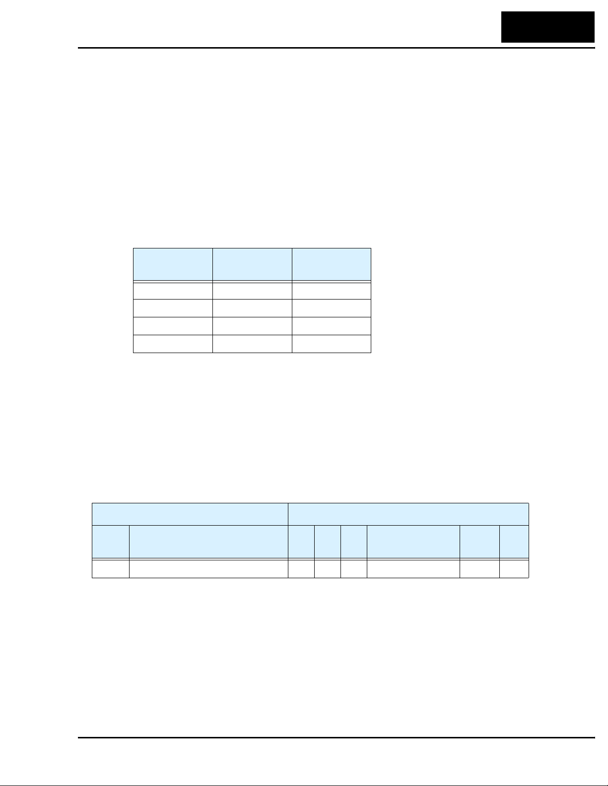
Step 8 – Use DeviceNet Explicit Messaging
The control sequences in Step 7 showed how the network host computer can control the
inverter via polled I/O. While polled I/O data is continuously supplied (on each network
scan), it contains only a small set of control bits and values for the main running profile.
In addition, the inverter provides a direct way host computer to access individual inverter
parameters. In DeviceNet terminology, it is called explicit messaging.
The DeviceNet standards provide for a way to address individual devices on the network
(nodes), and data (attributes) within each device. A complete address consists of four
numbers: the Node Address (MAC ID), the Object Class Identifier, the Instance Number,
and the Attribute Number. An explicit message connection between two devices uses
these four numbers to identify and transfer data on a DeviceNet network. The four
address components and their ranges are shown in the following table:
L100DN Inverter
61
Address
Component
Node 0 63
Class 1 65535
Instance 0 65535
Attribute 1 255
A particular inverter on the network has a specific node address (default = 63). To access
a particular parameter in that inverter, the host computer uses the class, instance, and
attribute numbers together. The address ranges indicated in the table above could access
any one of thousands of values within a device, if needed. In DeviceNet terminology, a
read access is called get, and a write access is called a set.
The assignment of DeviceNet explicit messaging addresses to inverters is somewhat
arbitrary. In this step we consider an example parameter, but the complete set for the
L100DN Series inverter is listed in the “Network Register Map” on page 78. The table
excerpt below shows parameter F_01 and its network address for explicit messaging.
“F” Group Parameters, Example DeviceNet Class ID = 100
Func.
Code
Name Inst Attr Size Range Scaling
Lowest Highest
Get/
Set
F_01 Output frequency setting 1 159 2 0 – 360Hz 100 Get
When you construct a get attribute or set attribute request, refer to the Class ID in the
table title bar (100), and the Inst, Attr, and Size columns (1, 159, 2).
Page 62

62
Network Control and Monitoring
A get attribute request from the host computer and the inverter’s response is shown in
the diagram below.
Host sends get attribute request:
Node = 63
Class = 100
Instance = 1
Attribute = 159
Size = 2 bytes
Inverter sends response:
5DCh (hex), or
1500 decimal
To perform the network request for parameter F_01 in the inverter, do the following:
a. Verify that your DeviceNet is running and the host computer is scanning.
b. In your host computer application, locate the mechanism for explicit messaging.
Refer to your host computer documentation if necessary.
c. Enter the node, class, Instance, attribute and size numbers in the above diagram.
d. Set the preferred display data format (hex or decimal) of the response (if your
host application provides this.
e. Have the host computer send the explicit message.
f. Verify the inverter’s response is 5DCh, or 1500 decimal. If not, check the values
in the get attribute request, and check the present value of parameter F_01 at the
inverter.
g. Apply the scale factor in the Network Register Map table. For F_01, divide by
100, so “1500” becomes 15.00Hz.
A set attribute request works similarly, but you must choose a parameter that permits a
set operation. refer to the right-most column of the table for Get/Set permissions.
Addr = 63
Page 63

Step 9 – Create a Host Computer Control Program
This section will provide an outline for constructing an example program for your host
computer control application. The example will use a simple forward and reverse
rotation for the velocity profile. Control programs for DeviceNet exist in a variety of
languages (relay ladder logic, flow charts, high-level language, etc.). Therefore, the
example program will be generic. It will use polled I/O for sending the basic commands
and to get parameters, but your program could also use explicit messaging to access any
inverter parameter.
The following diagram shows the polled I/O data transmitted on a single network scan.
At the moment of the scan, the inverter output is running the motor in the forward direction at 20.00Hz. The acceleration and deceleration times are set to 10.0 seconds.
Polled I/O Data
Host output data, 4 words
Word 0 – Command bits 0061h 97
Word 1 – Output freq. 07D0h 2000
Word 2 – Accel value 0064h 100
Word 3 – Decel value 0064h 100
L100DN Inverter
63
Host input data, 4 words
Word 0 – Status 0111h 273
Word 1 – Freq. monitor 07D0h 2000
Word 2 – Current monitor000Bh 11
Word 3 – Trip code 0000h 0
The figure below shows the velocity profile for the example program. It consists of a
forward rotation followed by a reverse rotation. The program will send the commands
and parameter values to set the speed and accel/decel values.
Program Example
accel/decel = 10sec.
f
Forward
rotation
Reverse
rotation
freq. = 25Hz
freq. = 10Hz
accel/decel = 20sec.
freq. = 15Hz
t
Command Bit Sequencing – The order of 0-to-1 transitions of the host computer’s
Word 0 command bits is important. First, set the Network Control bit (bit 5) and/or the
Network Reference bit (bit 6) as needed. Then you can set the FW Run or RV Run bit to
rotate the motor. If either Run bit is set = 1 before the Network Control bit is set = 1, the
inverter will ignore the request.
Page 64

64
Network Control and Monitoring
Example Program Sequence – The following host computer example program uses a
flowchart to send commands and values to the inverter (host output, 4 words). The
example HMI (Human-Machine Interface) data display shows the host monitoring the
inverter data (host input, 4 words). All number values are in decimal format.
Example Program
Set Network Control bit = 1
Set Network Reference bit = 1
Set output frequency = 25.00Hz
Set accel time = 10.0 seconds
Set decel time = 10.0 seconds
Set FW Run bit = 1
Wait 15 seconds
Set output frequency = 10.00Hz
Wait 15 seconds
Set FW Run bit = 0
Wait 20 seconds
Set output frequency = 15.0 Hz
Set accel/decel times = 20 sec.
Example HMI Data Displays
FW Run = 0
RV Run = 0
Freq. monitor = 0.00Hz
Current monitor = 0.0A
Trip code = 0
FW Run = 1
RV Run = 0
Freq. monitor = 25.0Hz
Current monitor = 1.1A
Trip code = 0
FW Run = 1
RV Run = 0
Freq. monitor = 10.00Hz
Current monitor = 1.1A
Trip code = 0
FW Run = 0
RV Run = 0
Freq. monitor = 0.0Hz
Current monitor = 0.0A
Trip code = 0
Freq. Arrival = 0
Run Mode = 0
Freq. Arrival = 1
Run Mode = 1
Freq. Arrival = 1
Run Mode = 1
Freq. Arrival = 0
Run Mode = 0
Set RV Run bit = 1
Wait 15 seconds
Set RV Run bit = 0
FW Run = 0
RV Run = 1
Freq. monitor = 15.00Hz
Current monitor = 1.1A
Trip code = 0
FW Run = 0
RV Run = 0
Freq. monitor = 0.00Hz
Current monitor = 0.0A
Trip code = 0
Freq. Arrival = 1
Run Mode = 1
Freq. Arrival = 0
Run Mode = 0
Page 65

L100DN Inverter
The diagram below shows the example inverter output velocity profile. The dashed lines
correlate a profile change with the DeviceNet data related to that event. Data is in hex
format. A value of “xxxx” means the value is changing at that point in the profile.
Program Example With Data
65
Forward
rotation
Reverse
rotation
Host output
(hex)
Word 0:
Word 1:
Word 2:
Word 3:
Host input
(hex)
Word 0:
Word 1:
Word 2:
Word 3:
1
0060
09C4
0064
0064
0000
0000
0000
0000
freq. = 25Hz
accel/decel = 10sec.
f
freq. = 10Hz
2 3 4 5 8
0061
09C4
0064
0064
0101
xxxx
xxxx
0000
0061
09C4
0064
0064
0111
09C4
xxxx
0000
0061
03E8
0064
0064
0101
xxxx
xxxx
0000
0061
03E8
0064
0064
0111
03E8
xxxx
0000
0060
03E8
0064
0064
0101
xxxx
xxxx
0000
0060
03E8
0064
0064
0000
0000
0000
0000
0062
05DC
0064
0064
0102
xxxx
xxxx
0000
accel/decel = 20sec.
freq. = 15Hz
9 10 116 7
0062
05DC
00C8
00C8
0112
05DC
xxxx
0000
0060
05DC
00C8
00C8
0102
xxxx
xxxx
0000
0060
05DC
00C8
00C8
0000
0000
0000
0000
t
Host Computer L100DN Inverter
Timeline
Step
Action Cmd Freq.
Accel/
Decel
Response Status
1 Stop 0060h 25 Hz 10 sec. Stop 0000h 0000h
2 FW Run 0061h 25.00 =
3 Constant speed 0111h 09C4h
09C4h
4 Change speed same 10 Hz
5 Constant speed 0111h 03E8h
10.00 =
03E8
10 =
Accel stage 0101h xxxxh
0064h
same Decel stage 0101h xxxxh
6 Stop 0060h same same Decel stage 0101h xxxxh
7 Stop 0000h 0000h
8 RV run 0062h 15 Hz
9 Constant speed 0112h 05DCh
15.00 =
05DCh
20 sec.
=
00C8h
Accel stage 0102h xxxxh
10 Stop 0060h same same Decel stage 0102h xxxxh
11 Stop 0000h 0000h
Freq.
Mon.
Page 66
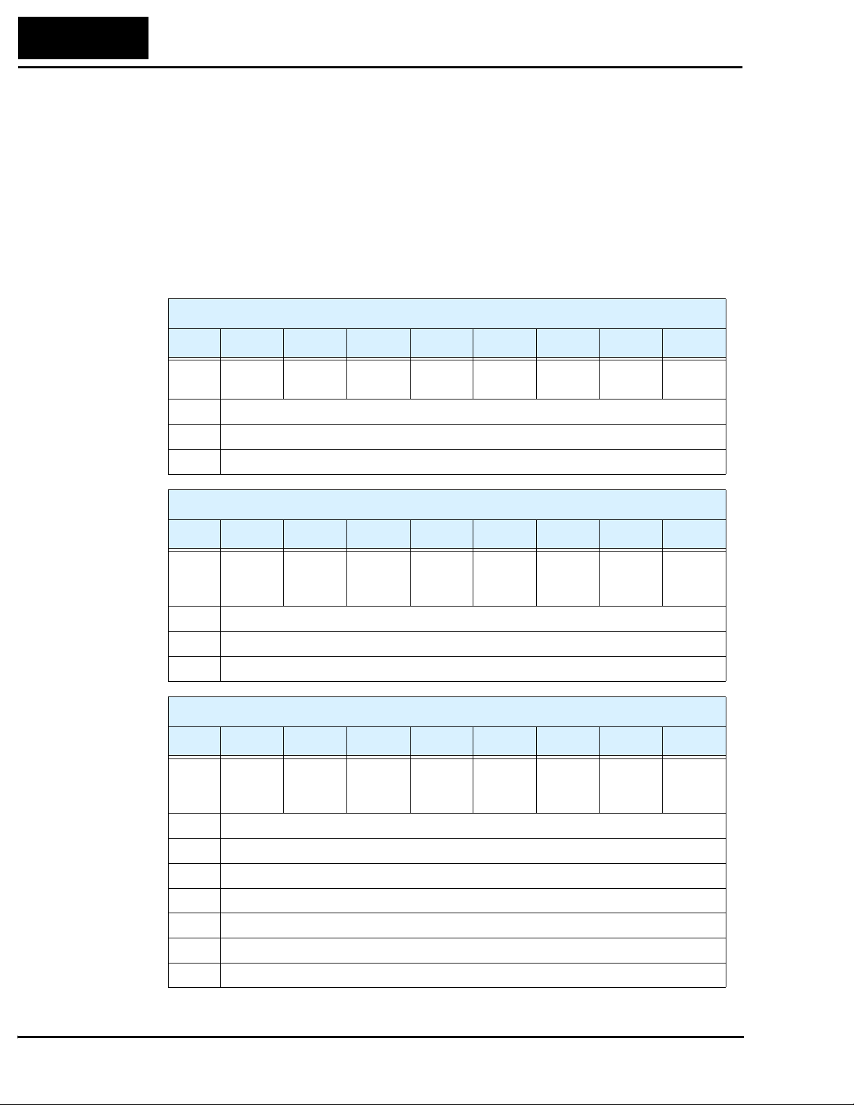
66
Network Control and Monitoring
Polled I/O Configurations
L100DN inverters offer three host output and host input polled I/O data configurations.
These correspond to P_46 / P_47 = 20 / 70, 21 / 71, or 100 / 101. Each configuration
differs in its use of up to 4 output or 4 input words (other combinations can cause
network errors.) The DeviceNet networking example in the previous steps used the
default polled I/O configuration (P_46 = 100 and P_47 = 101). This section describes
each available polled I/O configuration
Host Output Instance Configurations – The tables below list the three configurations
for host output data (settable by P_46).
Byte Bit 7 Bit 6 Bit 5 Bit 4 Bit 3 Bit 2 Bit 1 Bit 0
Inverter Consumed Data, (Host) Output Instance (P_46) = 20
0—————Fault
Reset
1—
2 Output frequency (low byte), host override for F_01 value
3 Output frequency (high byte), host override for F_01 value
Inverter Consumed Data, (Host) Output Instance (P_46) = 21
Byte Bit 7 Bit 6 Bit 5 Bit 4 Bit 3 Bit 2 Bit 1 Bit 0
0 — Network
Refer-
ence
1—
2 Output frequency (low byte), host override for F_01 value
3 Output frequency (high byte), host override for F_01 value
Inverter Consumed Data, (Host) Output Instance (P_46) = 100
Byte Bit 7 Bit 6 Bit 5 Bit 4 Bit 3 Bit 2 Bit 1 Bit 0
0 — Network
Refer-
ence
Network
Control
Network
Control
— — Fault
Reset
— Free run
Stop
Fault
Reset
—FW Run
RV Run FW Ru n
RV Run FW Ru n
1—
2 Output frequency (low byte), host override for F_01 value
3 Output frequency (high byte), host override for F_01 value
4 Acceleration time (low byte), host override for F_02 value
5 Acceleration time (high byte), host override for F_02 value
6 Deceleration time (low byte), host override for F_03 value
7 Deceleration time (high byte), host override for F_03 value
Page 67
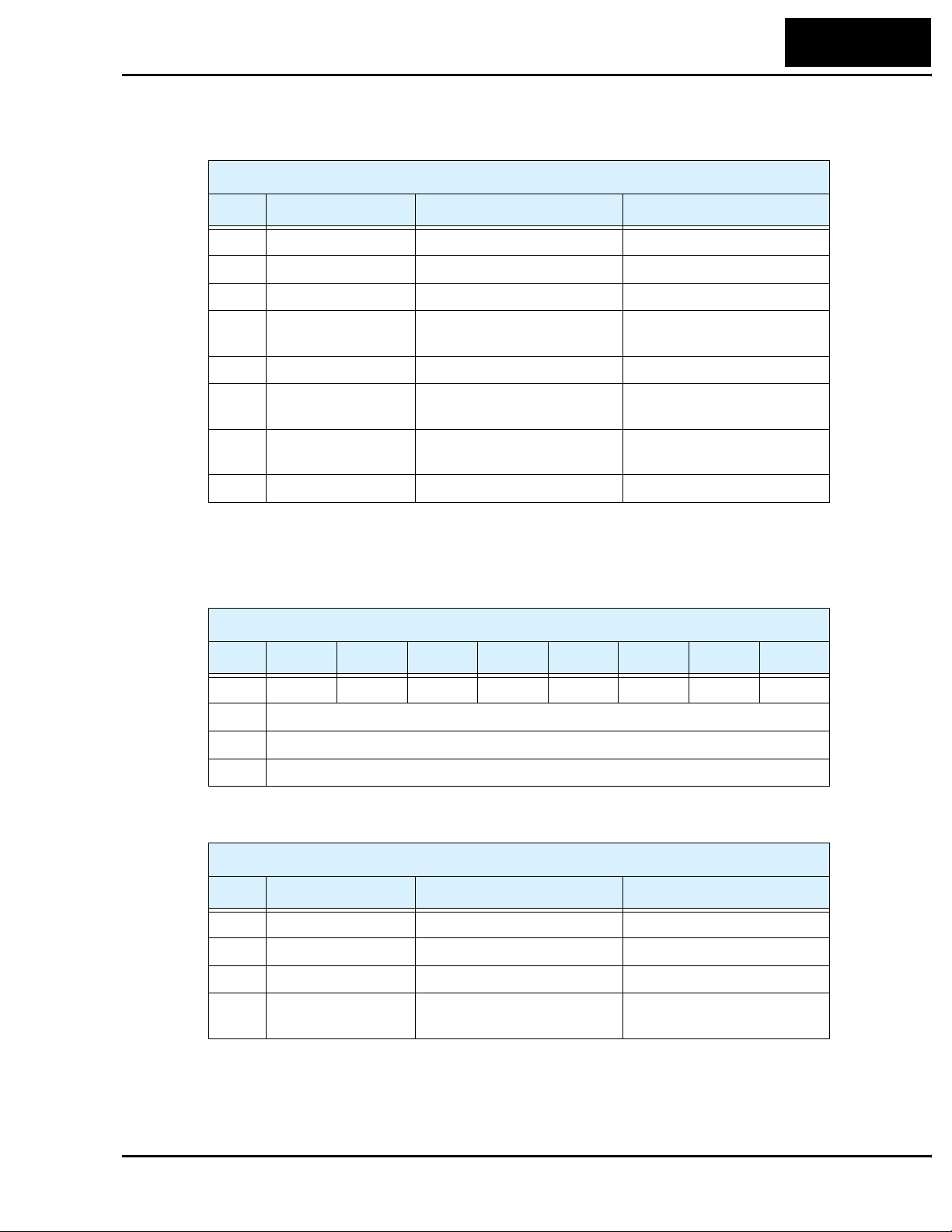
L100DN Inverter
The control bits (Byte 0) of each host output instance use some or all of the bits defined
in the following table.
Inverter Consumed Data, Control Byte
Bit Name Bit = 0 Bit = 1
0 FW Run Stop FW Run command
1 RV Run Stop RV Run command
2 Fault Reset — Reset the inverter, clear trip
3 Free Run Stop — Cause motor to free run
(coast) and stop
4— — —
67
5 Network Control Run/Stop control is local to
inverter
6 Network Reference Output freq. / accel / decel is
from F_01, F_02, F_03
7— — —
Run/Stop control is from
network host polled I/O
Output freq. / accel / decel is
from network host polled I/O
Host Input Instance Configurations – The following tables list the three configurations for host input data (settable by P_47).
Inverter Produced Data, (Host) Input Instance (P_47) = 70
Byte Bit 7 Bit 6 Bit 5 Bit 4 Bit 3 Bit 2 Bit 1 Bit 0
0—————FW Run—Trip
1 Inverter status (see status code table, next page)
2 Output frequency monitor (low byte), D_01 value
3 Output frequency monitor (high byte), D_01 value
The table below expands Byte 0 in the preceding table.
Inverter Produced Data, Status Byte
Bit Name Bit = 0 Bit = 1
0 Trip No faults exist Trip exists, not cleared
1— — —
2 FW Run Inverter stopped or in RV Inverter in FW Run
3, 4, 5,
6, 7
—— —
Page 68

68
Network Control and Monitoring
Inverter Produced Data, (Host) Input Instance (P_47) = 71
Byte Bit 7 Bit 6 Bit 5 Bit 4 Bit 3 Bit 2 Bit 1 Bit 0
0 Freq.
Arrival
1 Inverter status (see status code table, next page)
2 Output frequency monitor (low byte), D_01 value
3 Output frequency monitor (high byte), D_01 value
Network
Refer-
ence
Network
Control
Ready RV Run FW Run Warning Trip
The table below expands Byte 0 in the preceding table.
Inverter Produced Data, Status Byte
Bit Name Bit = 0 Bit = 1
0 Trip No faults exist Trip exists, not cleared
1 Warning No warning exists Warning condition exists
2 FW Run Inverter stopped or in RV Inverter in FW Run
3 RV Run Inverter stopped or in FW Inverter in RV Run
4 Ready Inverter is not ready Inverter is ready
(status byte code = 3, 4, or 5)
5 Network Control Run/Stop control is local to
inverter
Run/Stop control is from
network host polled I/O
6 Network Reference Output freq. / accel / decel is
from F_01, F_02, F_03
7 Frequency Arrival Inverter stopped, or in accel or
decel
Output freq. / accel / decel is
from network host polled I/O
Inverter output arrived at
target freq.
Inverter Produced Data, (Host) Input Instance (P_47) = 101
Byte Bit 7 Bit 6 Bit 5 Bit 4 Bit 3 Bit 2 Bit 1 Bit 0
0 Input
term. [3]
1 Inverter status (see status code table, next page)
2 Output frequency monitor (low byte), D_01 value
3 Output frequency monitor (high byte), D_01 value
4 Output current monitor (low byte), D_02 value
5 Output current monitor (high byte), D_02 value
6 Trip error code, D_08 value
7—
Input
term. [2]
Input
term. [1]
Freq.
Arrival
—TripRV RunFW Run
Page 69

L100DN Inverter
The table below expands Byte 0 in the preceding table.
Inverter Produced Data, Status Byte
Bit Name Bit = 0 Bit = 1
0 FW Run Inverter stopped or in RV Inverter in FW Run
1 RV Run Inverter stopped or in FW Inverter in RV Run
2 Trip No faults exist Trip exists, not cleared
3— — —
69
4 Frequency arrival Inverter stopped, or in accel or
decel
5 Input terminal [1] Input [1] = OFF Input [1] = ON
6 Input terminal [2] Input [2] = OFF Input [2] = ON
7 Input terminal [3] Input [3] = OFF Input [3] = ON
Inverter output arrived at
target freq.
Inverter Status – The following table describes the Inverter Status (Byte 1) for all host
output instances (P_47=70, P_47=71, and P_47=101).
Inverter Produced Data, Inverter State Code Byte
Code
(dec.)
0 The inverter is Stop Mode.
1 The inverter is in Run Mode.
2 The inverter is in Jog Mode.
3 The inverter is in Stop Mode and the motor output is free running (coasting).
4 The inverter is executing DC braking (includes CD braking wait time).
Description
5 The inverter is attempting a restart with frequency matching (B_01 = 03).
6 The output is stopped for an instantaneous power failure.
7 The inverter is attempting a restart with frequency matching (B_01 = 02).
8 The inverter is waiting before it attempts a restart with frequency matching. The wait
time is set by parameter B_03.
9 The inverter is in a trip condition, and is storing the trip history data to EEPROM. A
Stop/Reset command to clear the trip is ignored in this state.
10 The inverter is in a trip condition.
11 An under-voltage condition exists at the inverter power input.
Page 70

70
Troubleshooting and Maintenance
Troubleshooting and Maintenance
This section describes L100DN Series error codes corresponding to Chapter 6,
“Troubleshooting and Maintenance,” in the L100 Inverter Instruction Manual.
Error Codes and Notes
L100DN Series inverters have the additional error code listed below.
Error
Code
E60
A DeviceNet communication error will result in an inverter trip with error code 60, as
well as other actions that you can specify. The table below lists the DeviceNet fault types
detected and the inverter actions.
Bus-OFF detection *1 P_45 setting (*2), five options:
DeviceNet watchdog timer time-out
(time period in P_44 setting) *3
Communication error
DeviceNet Error Type Inverter Action
Name Cause(s)
• The DeviceNet cable may be disconnected or have
an open wire, short, etc.
• The communication error may be due to the
external device. Check whether the interruption is
for more than 3 seconds before resetting the error.
If so, the watchdog timer in the inverter is timing
out due to no response from the external device.
00 .. Trip
01 .. Decelerate and trip
02 .. Hold last speed
03 .. Free-run stop
04 .. Decelerate and stop
(same as above)
DeviceNet connection time-out *4 Decelerate and trip
Connection released *5 Decelerate and trip
Note 1: The inverter does not support DeviceNet requests during a communication
fault. To clear a Bus-OFF error, power cycle the inverter or reset it via [RS].
Note 2: The P_45 setting only applies to the inverter’s DeviceNet watchdog timer
time-out, not a connection time-out or a host connection release event.
Note 3: The inverter’s DeviceNet watchdog timer is active whenever the inverter is in
Run Mode and its DeviceNet connection is enabled. (The DeviceNet connection may be enabled either by P_43 = 1 or when the signal is ON at the intelligent input terminal [DNT], if assigned. [DNT] input has priority over P_43.)
Note 4: The DeviceNet connection time-out refers to the time-out within the
DeviceNet Connection Object, per the DeviceNet specifications. In if Run
Mode when the time-out occurs, the inverter decelerates the motor to a stop.
Note 5: The host computer can release the connection to the inverter via the standard
service release mechanism. In if Run Mode when the time-out occurs, the
inverter decelerates the motor to a stop.
Page 71

Appendix A:
DeviceNet Object Lists
This appendix contains DeviceNet Object Lists for the inverter to comply with
DeviceNet specifications. Some host computer applications automatically handle the
low-level details of object list attributes. So, you may or may not need this information
when developing your host application program.
Category Item Description
L100DN Inverter
71
Device Profile
General Device
Data
Physical
conformance data
Communication
Data
DeviceNet Specification,
conforms to version #
Vendor name Hitachi, Ltd. (Vendor ID = 74)
Device profile name AC Drive (Profile number = 2)
Product catalog number —
Product revision 3.1
Network power consumption 50mA at 11VDC
Connector style Open-pluggable
Isolated physical layer Yes
LEDs supported Module Status LED
Default MAC ID 63
Baud rate selection Software selectable
Baud rate settings 125, 250, and 500 k bits/sec.
DeviceNet network behavior Group 2 server only
UCMM supported No
DeviceNet connection
supported
Volume I – Release 2.0
Volume II – Release 2.0
Network Status LED
Polled I/O, Explicit Messaging
Fragmented explicit messaging supported
Yes, acknowledge time-out = 1200ms
Page 72

72
DeviceNet Object Lists
The DeviceNet object lists in this section contain data types that are identified by
DeviceNet standard acronyms, defined in the following table:
Acronym Data Type Description Range
BOOL Boolean Bit
BYTE Bit string 1 Byte (8 bits)
WORD Bit string 2 Bytes (16 bits)
STRING String Variable bits, variable range
USINT Unsigned short integer Int (1 Byte) – (0...255)
UINT Unsigned integer Int (2 Bytes) – (0...65535)
UDINT Unsigned double integer
SINT Signed short integer Int (1 Byte) – (–128...+127)
INT Signed integer Int (2 Bytes) – (–32768...+32767)
DINT Signed double integer
Int (4 Bytes) – (0...2
Int (4 Bytes) – (–2
32
–1)
31
...+231–1)
In the following Object tables, the Class ID numbers are in hex format.
Identity Object (Class ID = 1 hex)
Category Attribute ID
Class (not supported) — — — —
Instance 1 Vendor ID 1 Get UINT 74
Device type 2 Get UINT 2 (AC drive)
Product code 3 Get UINT L100DN2 =
Major revision 4 Get USINT 3
Minor revision Get USINT 2
Status 5 Get WORD 0
Serial number 6 Get UDINT Factory
Product name 7 Get STRING “L100DN”
Access
Rule
Data Type Initialization
0702h
initialized
Supported Services, Identity Object
Service Name Code Description
Get_Attribute_Single 0Eh
Reset 05h 0 .....Reset
1..... History clear and data initialize
NOP 17h
Page 73

L100DN Inverter
Error Responses to Set_Attribute_Single – In certain conditions the inverter cannot
Set an attribute as the host has requested. For example, the host’s data might be out-ofrange for the specified parameter. The inverter will return an error code, listed for the
specific condition in the table below.
73
Error Condition Type
The inverter is in Run Mode Device state conflict 10h 00
A trip, undervoltage, or trip-retry exists 01
Software lock mode enabled 02
Value less than start frequency setting Invalid parameter
Value less than lower frequency limit setting 01
Value more than upper frequency limit setting 02
Value more than maximum frequency setting 03
Out-of-range condition not listed above Invalid parameter 04
(check F_01, A_03,
A_20–A_35, A_38,
A_52, A_61, A_62)
Type
code
20h 00
Specific
error code
NOTE: The Message Router Object (Class ID = 2 hex) is supported, but has no setting.
DeviceNet Object (Class ID = 3 hex)
Category Attribute ID
Access
Rule
Data Type Initialization
Class Revision 1 Get UINT 2
Instance 1 MAC ID 1 Get/Set USINT 63
Baud rate 2 Get/Set USINT 125k bits/sec.
BOI 3 Get BOOL 0
Bus OFF counter 4 Get/Set USINT 0
Allocation information choice
byte
Master’s MAC ID — — USINT —
5Get BYTE —
Supported Services, DeviceNet Object
Service Name Code Description
Get_Attribute_Single 0Eh
Set_Attribute_Single 10h
Allocate_M/S_Connection_Set 4Bh
Release_M/S_Connection_Set 4Ch
Page 74
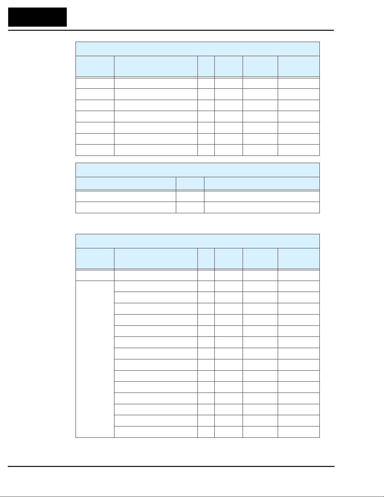
74
DeviceNet Object Lists
Assembly Object (Class ID = 4 hex)
Category Attribute ID
Class (not supported) — — — —
Instance 20 DATA 3 Get/Set 4 Bytes —
Instance 21 DATA 3 Get/Set 4 Bytes —
Instance 70 DATA 3 Get 4 Bytes —
Instance 71 DATA 3 Get 4 Bytes —
Instance 100 DATA 3 Get/Set 8 Bytes —
Instance 101 DATA 3 Get 8 Bytes —
Access
Rule
Data Type Initialization
Supported Services, Assembly Object
Service Name Code Description
Get_Attribute_Single 0Eh
Set_Attribute_Single 10h
Connection Object (Class ID = 5 hex)
Category Attribute ID
Class (not supported) — — — —
Instance 1 State 1 Get USINT —
Instance type 2 Get USINT 00
Transport class trigger 3 Get BYTE 83h
Produced connection ID 4 Get UINT —
Consumed connection ID 5 Get UINT —
Initial comm. characteristics 6 Get BYTE 21h
Produced connection size 7 Get UINT C8h
Consumed connection size 8 Get UINT C8h
Expected packet rate 9 Get/Set UINT 09C4h
Watchdog time-out action 12 Get/Set USINT 1
Produced conn. path length 13 Get UINT 0
Produced connection path 14 Get UINT array —
Consumed conn. path length 15 Get UINT 0
Consumed connection path 16 Get UINT array —
Access
Rule
Data Type Initialization
Page 75

Connection Object (Class ID = 5 hex)
L100DN Inverter
75
Category Attribute ID
Instance 2 State 1 Get USINT —
Instance type 2 Get USINT 01
Transport class trigger 3 Get BYTE 82h
Produced connection ID 4 Get UINT —
Consumed connection ID 5 Get UINT —
Initial comm. characteristics 6 Get BYTE 01h
Produced connection size 7 Get UINT 08h
Consumed connection size 8 Get UINT 08h
Expected packet rate 9 Get/Set UINT 03E8h
Watchdog time-out action 12 Get/Set USINT 0
Produced conn. path length 13 Get UINT 3
Produced connection path 14 Get UINT array 623625
Consumed conn. path length 15 Get UINT 3
Consumed connection path 16 Get UINT array 623624
Access
Rule
Data Type Initialization
Supported Services, Connection Object
Service Name Code Description
Reset 05h
Get_Attribute_Single 0Eh
Set_Attribute_Single 10h
Page 76

76
DeviceNet Object Lists
Motor Data Object (Class ID = 28 hex)
Category Attribute ID
Class Revision 1 Get WORD 0001
Instance 1 Motor Type 3 Get BYTE 07
Rated Current 6 Get/Set WORD B_12
Rated Voltage 7 Get/Set WORD A_82
Pole Count 12 Get/Set WORD P_49
Access
Rule
Data Type Initialization
Supported Services, Motor Data Object
Service Name Code Description
Get_Attribute_Single 0Eh
Set_Attribute_Single 10h
Control Supervisor Object (Class ID = 29 hex)
Category Attribute ID
Access
Rule
Data Type Initialization
Class Revision 1 Get WORD 0001
Instance 1 Run1 3 Get/Set BYTE 00
Run2 4 Get/Set BYTE 00
Network Control 5 Get/Set BYTE 00
State 6 Get BYTE —
Running1 7 Get BYTE 00
Running2 8 Get BYTE 00
Ready 9 Get BYTE 00
Faulted 10 Get BYTE 00
Warni ng 11 Ge t B YTE 0 0
Fault reset 12 Get/Set BYTE 00
Fault code 13 Get WORD 0000
Control from Network 15 Get BYTE 00
DN fault mode 16 Get BYTE 02
Force fault/trip 17 Get/Set BYTE 00
Force status 18 Get BYTE 00
Page 77
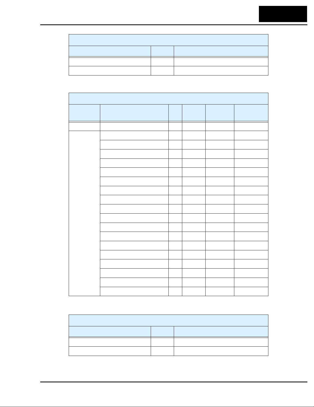
Supported Services, Control Supervisor Object
Service Name Code Description
Get_Attribute_Single 0Eh
Set_Attribute_Single 10h
AC/DC Drive Object (Class ID = 2A hex)
L100DN Inverter
77
Category Attribute ID
Class Revision 1 Get WORD 0001
Instance 1 At Reference 3 Get BYTE 00
Network Reference 4 Get/Set BYTE 00
Drive mode 6 Get BYTE 01
Speed, actual 7 Get WORD 0000
Speed reference 8 Get/Set WORD F_01 setting
Current, actual 9 Get WORD 0000
Current limit 10 Get/Set WORD B_21 setting
Input voltage 16 Get WORD —
Output voltage 17 Get WORD 0000
Accel time 18 Get/Set WORD F_02 setting
Decel time 19 Get/Set WORD F_03 setting
Low speed limit 20 Get/Set WORD A_62 setting
High speed limit 21 Get/Set WORD A_04 setting
Speed scale 22 Get/Set BYTE 00
Access
Rule
Data Type Initialization
Current scale 23 Get/Set BYTE 00
Voltage scale 27 Get/Set BYTE 00
Time scale 28 Get/Set BYTE 00
Reference from network 29 Get BYTE 00
Supported Services, AC/DC Drive Object
Service Name Code Description
Get_Attribute_Single 0Eh
Set_Attribute_Single 10h
Page 78

78
Appendix B:
Appendix B:
Network Register Map
The following tables list the DeviceNet explicit addressing to access inverter parameters.
Each parameters address consists of Class ID, Instance, and Attribute. The host will also
need to use the Size (number of bytes) in the request. Most of the parameters provide
both Get and Set access (denoted by “G/S”) in the tables).
The inverter returns scalar values in decimal format. The scale factors are presented in
the Scaling column. To get a parameter’s actual value, the host computer will need to
divide the data by the scale factor (unless it is “1”). The result will be a decimal number
with an integer part and a decimal (fractional) part.
Main Profile Parameters and Basic Inverter Data
“D” Group Parameters and
Basic Inverter Data
Func.
Code
— Rated capacity 1 100 1 1 0.2 kW
— Input AC voltage class 1 101 1 1 200V
— Rated output current 1 102 2 0.00 – 655.35A 100 Get
— Inverter status 1 103 1 0 – 255 1 Get
D_01 Output frequency monitor 1 104 2 0.01 – 360.00Hz 100 Get
Name Inst Attr Size Range Scaling
DeviceNet Class ID = 100
Get/
Set
—Get
2 0.4 kW
3 0.55 kW
4 0.75kW
5 1.1 kW
6 1.5 kW
7 2.2 kW
8 8.3 kW
9 3.7 kW
10 4.0 kW
11 5.5 kW
12 7.5 kW
—Get
2 400V
D_02 Output current monitor 1 105 2 0.00 – 655.35A 10 Get
D_03 Rotation direction monitor 1 106 1 1 forward
2reverse
D_05 Intelligent input terminal status 1 108 1 0 open
1close,
Bit 0 = terminal 1
Bit 1 = terminal 2
Bit 2 = terminal 3
—Get
—Get
Page 79

L100DN Inverter
79
“D” Group Parameters and
Basic Inverter Data
Func.
Code
D_06 Intelligent output terminal status 1 109 1 0 open
D_07 Scaled output frequency monitor 1 110 4 0.00–35964.00Hz
D_16 Cumulative operation RUN time
monitor
— P–N voltage monitor 1 118 2 0.0 – 6553.5V 10 Get
— Rate of BRD loading 1 119 1 0 – 100% 1 Get
— Rate of electronic thermal
loading
— Trip count 1 121 1 0 – 255 1 Get
D_08 Trip event monitor (nth trip) 1 122 1 00 to 60 (see Ch.6
Name Inst Attr Size Range Scaling
1 115 4 0 – FFFFFFh
1 120 1 0 – 100% 1 Get
DeviceNet Class ID = 100
—Get
1close,
Bit 0 = terminal 11
Bit 1 = terminal 12
100 Get
(= 360 * 99.9)
1Get
(hex) hours
—Get
in manual)
Get/
Set
Output frequency at trip point 1 123 2 0.01 – 360Hz 100 Get
Motor current at trip point 1 124 2 0.00 – 655.35A 100 Get
DC bus voltage at trip point 1 125 2 0.0 – 6553.5V 10 Get
Cumulative operation RUN time
at trip point
D_09 Trip event monitor (nth-1 trip) 1 128 1 00 to 60 (see Ch.6
Output frequency at trip point 1 129 2 0.01 – 360Hz 100 Get
Motor current at trip point 1 130 2 0.00 – 655.35A 100 Get
DC bus voltage at trip point 1 131 2 0.0 – 6553.5V 10 Get
Cumulative operation RUN time
at trip point
D_09 Trip event monitor (nth-2 trip) 1 134 1 00 to 60 (see Ch.6
Output frequency at trip point 1 135 2 0.01 – 360Hz 100 Get
Motor current at trip point 1 136 2 0.00 – 655.35A 100 Get
DC bus voltage at trip point 1 137 2 0.0 – 6553.5V 10 Get
1 126 4 0 – FFFFFFh
(hex) hours
in manual)
1 132 4 0 – FFFFFFh
(hex) hours
in manual)
1Get
—Get
1Get
—Get
Cumulative operation RUN time
at trip point
1 138 4 0 – FFFFFFh
(hex) hours
1Get
Page 80

80
Network Register Map
“F” Group Parameters and
Basic Inverter Data
Func.
Code
F_01 Output frequency setting 1 159 2 0 – 360Hz 100 Get
F_02 Acceleration (1) time setting 1 160 2 0.1 – 3000.0 sec. 10 Get
F_03 Deceleration (1) time setting 1 161 2 0.1 – 3000.0 sec. 10 Get
F_04 Keypad Run key routing 1 162 1 0 forward
— Input terminal functions monitor1 1 163 2 See EDS file — Get
— Input terminal functions monitor2 1 164 2 See EDS file — Get
— Input terminal functions setting1 1 165 2 See EDS file — Get
— Input terminal functions setting2 1 166 2 See EDS file — Get
— Output terminal functions
monitor
Name Inst Attr Size Range Scaling
1 167 1 See EDS file — Get
DeviceNet Class ID = 100
Get/
Set
—Get
1reverse
2 [F/R] terminal
Supported Services, DeviceNet Class ID = 100
Service Name Code Description
Reset 05h Initializes all parameters to factory default values,
excluding P_41 DeviceNet baud rate and P_42
DeviceNet MAC ID
Get_Attribute_Single 0Eh
Set_Attribute_Single 10h
Page 81

Standard Functions
“A” Group Parameters DeviceNet Class ID = 101
L100DN Inverter
81
Func.
Code
A_02 Run command source setting 1 102 1 1 Control
A_03 Base frequency setting 1 103 2 50Hz to maximum
A_04 Maximum frequency setting 1 104 2 Base freq. to
A_20 Multi-speed 0 setting 1 120 2 0.00 – 360.00Hz 100 G/S
A_21 Multi-speed 1 setting 1 121 2 0.00 – 360.00Hz 100 G/S
A_22 Multi-speed 2 setting 1 122 2 0.00 – 360.00Hz 100 G/S
A_23 Multi-speed 3 setting 1 123 2 0.00 – 360.00Hz 100 G/S
A_24 Multi-speed 4 setting 1 124 2 0.00 – 360.00Hz 100 G/S
A_25 Multi-speed 5 setting 1 125 2 0.00 – 360.00Hz 100 G/S
A_26 Multi-speed 6 setting 1 126 2 0.00 – 360.00Hz 100 G/S
A_27 Multi-speed 7 setting 1 127 2 0.00 – 360.00Hz 100 G/S
Name Inst Attr Size Range Scaling
—G/S
terminal
2 Run key on
keypad
frequency
360Hz
Get/
Set
1G/S
1G/S
A_28 Multi-speed 8 setting 1 128 2 0.00 – 360.00Hz 100 G/S
A_29 Multi-speed 9 setting 1 129 2 0.00 – 360.00Hz 100 G/S
A_30 Multi-speed 10 setting 1 130 2 0.00 – 360.00Hz 100 G/S
A_31 Multi-speed 11 setting 1 131 2 0.00 – 360.00Hz 100 G/S
A_32 Multi-speed 12 setting 1 132 2 0.00 – 360.00Hz 100 G/S
A_33 Multi-speed 13 setting 1 133 2 0.00 – 360.00Hz 100 G/S
A_34 Multi-speed 14 setting 1 134 2 0.00 – 360.00Hz 100 G/S
A_35 Multi-speed 15 setting 1 135 2 0.00 – 360.00Hz 100 G/S
A_38 Jog frequency setting 1 138 2 0.5 – 9.99Hz 100 G/S
A_39 Jog stop mode 1 139 1 0 Free-run stop
1 Controlled
deceleration
2 DC braking to
stop
A_41 Torque boost method selection 1 141 1 0 Manual torque
boost
1 Automatic
torque boost
—G/S
—G/S
Page 82

82
Network Register Map
“A” Group Parameters DeviceNet Class ID = 101
Func.
Code
A_42 Manual torque boost value 1 142 1 0 – 99% 1 G/S
A_43 Manual torque boost frequency
adjustment
A_44 V/f characteristic curve selection 1 144 1 0 Constant torque
A_45 V/f gain setting 1 145 1 50 – 100% 1 G/S
A_51 DC braking enable 1 151 1 0 Disable
A_52 DC braking frequency setting 1 152 2 0.5 – 10.0Hz 100 G/S
A_53 DC braking wait time 1 153 1 0.1 – 5.0 sec. 10 G/S
A_54 DC braking force during deceler-
ation
A_55 DC braking time for deceleration 1 155 2 0.1 – 60.0 sec. 10 G/S
A_61 Frequency upper limit setting 1 161 2 0.0 Disable
A_62 Frequency lower limit setting 1 162 2 0.0 Disable
Name Inst Attr Size Range Scaling
1 143 2 0.0 – 50.0% 10 G/S
—G/S
1 Reduced torque
—G/S
1 Enable
1 154 1 0 – 100% 1 G/S
100 G/S
0.5 – 360.0Hz
100 G/S
0.5 – 360.0Hz
Get/
Set
A_63,
A_65,
A_67
A_64,
A_66,
A_68
A_81 AVR function select 1 181 1 0 AVR enabled
A_82 AVR voltage select 1 182 1 0 200V
A_92 Acceleration (2) time setting 1 192 2 0.1 – 3000.0 sec. 10 G/S
A_93 Deceleration (2) time setting 1 193 2 0.1 – 3000.0 sec. 10 G/S
Jump (center) frequency setting 1
Jump (hysteresis) frequency
width setting
163
1
165
1
167
1
164
1
166
1
168
2
0.0 – 360.0Hz 100 G/S
2
2
2
0.0 – 360.0Hz 100 G/S
2
2
—G/S
1 AVR disabled
2 AVR enabled
except during
deceleration
—G/S
1 220V
2 230V
3 240V
4 380V
5 400V
6 415V
7 440V
8 460V
Page 83
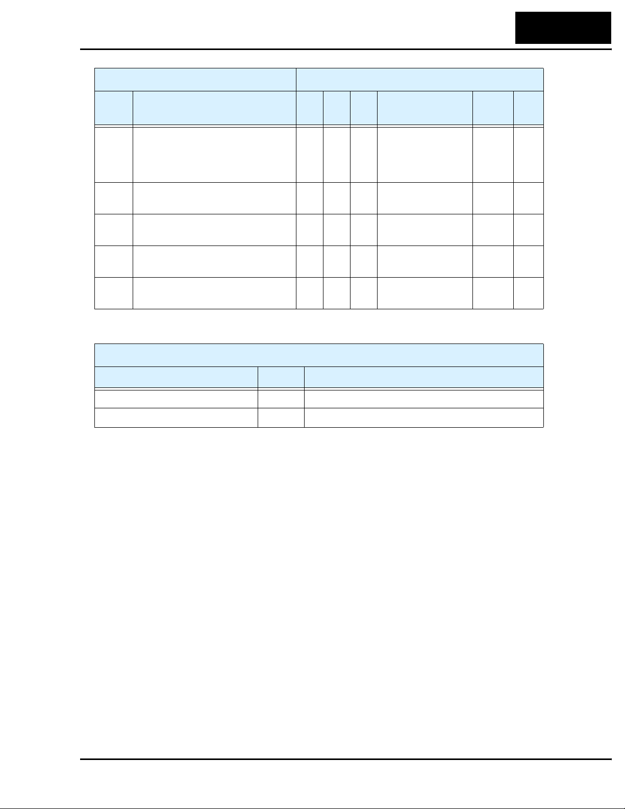
L100DN Inverter
“A” Group Parameters DeviceNet Class ID = 101
83
Func.
Code
A_94 Select method to switch to Acc2/
Dec2 profile
A_95 Acc1 to Acc2 frequency transi-
tion point
A_96 Dec1 to Dec2 frequency transi-
tion point
A_97 Acceleration curve selection 1 197 1 0 linear
A_98 Deceleration curve selection 1 198 1 0 linear
Service Name Code Description
Name Inst Attr Size Range Scaling
1 194 1 0 2CH input from
terminal
1 transition
frequency
1 195 2 0.0 – 360.0Hz 100 G/S
1 196 2 0.0 – 360.0Hz 100 G/S
1S-curve
1S-curve
Supported Services, DeviceNet Class ID = 101
Get/
Set
—G/S
—G/S
—G/S
Get_Attribute_Single 0Eh
Set_Attribute_Single 10h
Page 84

84
Network Register Map
Fine Tuning Functions
“B” Group Parameters DeviceNet Class ID = 103
Func.
Code
B_01 Selection of automatic restart
mode
B_02 Allowable under-voltage power
failure time
B_03 Retry wait time before motor
restart
B_12 Level of electronic thermal
setting
Name Inst Attr Size Range Scaling
Get/
Set
1 101 1 0 Alarm output
after trip, no
automatic restart
1 Restart at 0Hz
2 Resume operation after freq.
matching
3Resume
previous freq. after
freq. matching,
then decelerate to
stop and display
trip info.
1 102 2 0.3 – 25.0 sec. 10 G/S
1 103 2 0.3 – 100.0 sec. 10 G/S
1 112 2 5% to 120% rated
current, in A
—G/S
10 G/S
B_13 Electronic thermal characteristic 1 113 1 0 Reduced torque
1 Constant torque
2 Reduced
torque2
B_21 Overload restriction operation
mode
B_22 Overload restriction setting 1 122 2 50% to 150%
B_23 Deceleration rate at overload
restriction
1 121 1 0 Disabled
1 Enabled for
acceleration and
constant speed
2 Enabled for
constant speed
only
rated current, in A
1 123 2 0.3 – 30.0 10 G/S
—G/S
—G/S
100 G/S
Page 85

L100DN Inverter
“B” Group Parameters DeviceNet Class ID = 103
85
Func.
Code
B_31 Software lock mode selection 1 131 1 0 all parameters
B_32 Reactive current setting 1 132 2 0.00 to 32.00A 100 G/S
B_82 Start frequency adjustment 1 182 2 0.5 – 9.9 Hz 100 G/S
B_83 Carrier frequency setting 1 183 1 0.5 – 16.0kHz 10 G/S
B_84 Initialization mode (parameters
or trip history)
Name Inst Attr Size Range Scaling
—G/S
except B_31 are
locked if [SFT] is
ON
1 all parameters
except B_31 and
output freq. F_01
when [SFT] is ON
2 all parameters
except B_31 are
locked
3 all parameters
except B_31 and
F_01 are locked
1 184 1 0 Trip history
clear
1 Parameter
initialization
—G/S
Get/
Set
B_85 Country code for initialization 1 185 1 0 Japan version
1 Europe version
2US version
B_86 Frequency scaling conversion
factor
B_87 STOP key enable 1 187 1 0 Enabled
B_88 Restart mode after FRS 1 188 1 0 Restart from
Supported Services, DeviceNet Class ID = 103
Service Name Code Description
Get_Attribute_Single 0Eh
Set_Attribute_Single 10h
1 186 2 0.1 – 99.9 100 G/S
1 Disabled
0Hz
1 Restart from
real speed of
motor (frequency
matching)
—G/S
—G/S
—G/S
Page 86

86
Network Register Map
Intelligent Terminal Functions
“C” Group Parameters DeviceNet Class ID = 105
Func.
Code
C_01 Terminal [1] function 1 101 1 0, 1, 2, 3, 4, 5, 6, 9,
C_02 Terminal [2] function 1 102 1 (same as above) — G/S
C_03 Terminal [3] function 1 103 1 (same as above) — G/S
C_11 Terminal [1] active state 1 111 1 0 normally open
C_12 Terminal [2] active state 1 112 1 0 normally open
C_13 Terminal [3] active state 1 113 1 0 normally open
C_21 Terminal [11] function 1 121 1 0, 1, 2, 3, 5 (see
C_22 Terminal [12] function 1 122 1 (same as above) — G/S
Name Inst Attr Size Range Scaling
—G/S
11, 12, 13, 15, 18,
19, 20, 21, 22, 25,
27, 28, 31
(see manual,
Chapter 3)
—G/S
1 normally closed
—G/S
1 normally closed
—G/S
1 normally closed
—G/S
manual, Ch. 3)
Get/
Set
C_31 Terminal [11] active state 1 131 1 0 normally open
1 normally closed
C_32 Terminal [12] active state 1 132 1 0 normally open
1 normally closed
C_41 Overload level setting 1 141 2 0% to 200% rated
current, in A
C_42 Frequency arrival setting for
accel
C_43 Arrival frequency setting for
decel
Supported Services, DeviceNet Class ID = 105
Service Name Code Description
Get_Attribute_Single 0Eh
Set_Attribute_Single 10h
1 142 2 0.0 – 360.0Hz 100 G/S
1 143 2 0.0 – 360.0Hz 100 G/S
—G/S
—G/S
100 G/S
Page 87

DeviceNet Network Settings
“P” Group Parameters DeviceNet Class ID = 109
L100DN Inverter
87
Func.
Code
P_41 DeviceNet baud rate 1 141 1 0 125 kbaud
P_42 DeviceNet MAC ID 1 142 1 0 – 63 1 G/S
P_43 DeviceNet control enable 1 143 1 0 Disable
P_44 DeviceNet comm watchdog timer 2 144 2 0.00 – 99.99 sec. 100 G/S
P_45 Inverter action on DeviceNet
comm error
P_46 DeviceNet polled I/O: Output
instance number
P_47 DeviceNet polled I/O: Input
instance number
P_48 Inverter action on DeviceNet idle
mode
Name Inst Attr Size Range Scaling
—G/S
1 250 kbaud
2 500 kbaud
—G/S
1 Enable
1 145 1 0 Trip
1 Decel and trip
2 Hold last speed
3 Free run stop
4 Decel and stop
1 146 1 20, 21, 100 1 G/S
1 147 1 70, 71, 101 1 G/S
1 148 1 0 Trip
1 Decel and trip
2 Hold last speed
3 Free run stop
4 Decel and stop
—G/S
—G/S
Get/
Set
P_49 DeviceNet motor poles setting for
RPM
Supported Services, DeviceNet Class ID = 109
Service Name Code Description
Get_Attribute_Single 0Eh
Set_Attribute_Single 10h
1 149 1 0 – 38 (even
numbers only)
1G/S
Page 88

88
Appendix C:
Appendix C:
Drive Parameter Settings Tables
Introduction
This section lists the user-programmable parameters for the L100DN series inverters and
the default values, corresponding to Appendix B, “Drive Parameter Settings Tables,” in
the L100 Inverter Instruction Manual. The right-most column of the tables is blank, so
you can record values you have changed from the default. This involves just a few
parameters for most applications. This section presents the parameters in a format
oriented toward the keypad on the inverter.
Parameter Settings for Keypad Entry
L100 series inverters provide many functions and parameters that can be configured by
the user. We recommend that you record all parameters that have been edited, in order to
help in troubleshooting or recovery from a loss of parameter data.
Inverter model
MFG. No.
Main Profile Parameters
“F” Group Parameters Default Setting
Func.
Code
F_01 Output frequency setting 0.0 0.0 0.0
F_02 Acceleration (1) time setting 10.0 10.0 10.0
F_03 Deceleration (1) time setting 10.0 10.0 10.0
F_04 Keypad Run key routing 00 00 00
Name
L100
–FE
(Europe)
}
(USA)
This information is printed
on the specification label
located on the right side of
the inverter.
–FU
–F
(Japan)
User
Setting
Page 89

L100DN Inverter
Standard Functions
“A” Group Parameters Default Setting
Func.
Code
A_02 Run command source setting 01 01 02
A_03 Base frequency setting 50.0 60.0 60.0
A_04 Maximum frequency setting 50.0 60.0 60.0
A_20 Multi-speed 0 setting 0 0 0
A_21 Multi-speed 1 setting 0 0 5
A_22 Multi-speed 2 setting 0 0 10
A_23 Multi-speed 3 setting 0 0 15
A_24 Multi-speed 4 setting 0 0 20
A_25 Multi-speed 5 setting 0 0 30
Name
-FE
(Europe)
-FU
(USA)
–F
(Japan)
89
User
Setting
A_26 Multi-speed 6 setting 0 0 40
A_27 Multi-speed 7 setting 0 0 50
A_28 Multi-speed 8 setting 0 0 60
A_29 Multi-speed 9 setting 0 0 0
A_30 Multi-speed 10 setting 0 0 0
A_31 Multi-speed 11 setting 0 0 0
A_32 Multi-speed 12 setting 0 0 0
A_33 Multi-speed 13 setting 0 0 0
A_34 Multi-speed 14 setting 0 0 0
A_35 Multi-speed 15 setting 0 0 0
A_38 Jog frequency setting 1.0 1.0 1.0
A_39 Jog stop mode 00 00 00
A_41 Torque boost method selection 00 00 00
A_42 Manual torque boost value 11 11 11
A_43 Manual torque boost frequency
adjustment
10.0 10.0 10.0
A_44 V/f characteristic curve selection 00 00 00
A_45 V/f gain setting 100 100 100
A_51 DC braking enable 00 00 00
A_52 DC braking frequency setting 0.5 0.5 0.5
A_53 DC braking wait time 0.0 0.0 0.0
Page 90

90
Drive Parameter Settings Tables
“A” Group Parameters Default Setting
Func.
Code
Name
-FE
(Europe)
-FU
(USA)
–F
(Japan)
User
Setting
A_54 DC braking force during deceler-
ation
A_55 DC braking time for deceleration 0.0 0.0 0.0
A_61 Frequency upper limit setting 0.0 0.0 0.0
A_62 Frequency lower limit setting 0.0 0.0 0.0
A_63,
A_65,
A_67
A_64,
A_66,
A_68
A_81 AVR function select 02 00 02
A_82 AVR voltage select 230/400 230/460 200/400
A_92 Acceleration (2) time setting 15.0 15.0 15.0
A_93 Deceleration (2) time setting 15.0 15.0 15.0
A_94 Select method to switch to Acc2/
A_95 Acc1 to Acc2 frequency transi-
Jump (center) frequency setting 0.0 0.0 0.0
Jump (hysteresis) frequency
width setting
Dec2 profile
tion point
000
0.5 0.5 0.5
00 00 00
0.0 0.0 0.0
A_96 Dec1 to Dec2 frequency transi-
tion point
A_97 Acceleration curve selection 00 00 00
A_98 Deceleration curve selection 00 00 00
0.0 0.0 0.0
Page 91

Fine Tuning Functions
“B” Group Parameters Default Setting
Func.
Code
Name
-FE
(Europe)
-FU
(USA)
L100DN Inverter
User
–F
(Japan)
Setting
91
B_01 Selection of automatic restart
mode
B_02 Allowable under-voltage power
failure time
B_03 Retry wait time before motor
restart
B_12 Level of electronic thermal
setting
B_13 Electronic thermal characteristic 01 01 00
B_21 Overload restriction operation
mode
B_22 Overload restriction setting Rated
B_23 Deceleration rate at overload
restriction
B_31 Software lock mode selection 01 01 01
00 00 00
1.0 1.0 1.0
1.0 1.0 1.0
Rated
current for
each
inverter
01 01 01
current x
1.25
1.0 1.0 1.0
Rated
current for
each
inverter
Rated
current x
1.25
Rated
current for
each
inverter
Rated
current x
1.25
B_32 Reactive current setting Rated
current x
0.40
B_82 Start frequency adjustment 0.5 0.5 0.5
B_83 Carrier frequency setting 5.0 5.0 12.0
B_84 Initialization mode (parameters
or trip history)
B_85 Country code for initialization 01 02 00
B_86 Frequency scaling conversion
factor
B_87 STOP key enable 00 00 00
B_88 Restart mode after FRS 00 00 00
00 00 00
1.0 1.0 1.0
Rated
current x
0.40
Rated
current x
0.40
Page 92

92
Drive Parameter Settings Tables
Intelligent Terminal Functions
“C” Group Parameters Default Setting
Func.
Code
C_01 Terminal [1] function 00 00 00
C_02 Terminal [2] function 21 21 21
C_03 Terminal [3] function 12 12 12
C_11 Terminal [1] active state 00 00 00
C_12 Terminal [2] active state 00 00 00
C_13 Terminal [3] active state 00 00 00
C_21 Terminal [11] function 00 00 00
C_22 Terminal [12] function 05 05 05
C_31 Terminal [11] active state 00 00 00
Name
-FE
(Europe)
-FU
(USA)
–F
(Japan)
User
Setting
C_32 Terminal [12] active state 00 00 00
C_41 Overload level setting Inverter
rated
current
C_42 Frequency arrival setting for
accel
C_43 Arrival frequency setting for
decel
0.0 0.0 0.0
0.0 0.0 0.0
Inverter
rated
current
Inverter
rated
current
Page 93

L100DN Inverter
DeviceNet Network Settings
“P” Group Parameters Default Setting
Func.
Code
P_41 DeviceNet baud rate 00 00 00
P_42 DeviceNet MAC ID 63 63 63
P_43 DeviceNet control enable 01 01 01
P_44 DeviceNet comm watchdog timer 1.00 1.00 1.00
Name
–FE
(Europe)
–FU
(USA)
–F
(Japan)
93
User
Setting
P_45 Inverter action on DeviceNet
comm error
P_46 DeviceNet polled I/O: Output
instance number
P_47 DeviceNet polled I/O: Input
instance number
P_48 Inverter action on DeviceNet idle
mode
P_49 DeviceNet motor poles setting for
RPM
01 01 01
100 100 100
101 101 101
01 01 01
00 00 00
Page 94

94
Appendix D:
Appendix D:
Restoring Factory Default Settings
Keypad Method – You can restore (initialize) all inverter parameters to factory default
settings from the keypad. (The network method via DeviceNet is on the next page.) After
initializing the inverter, use the powerup test in to get the motor running again.
No. Action Display Func./Parameter
1
Use the , , and keys to
navigate to the “B” Group.
2
Press the key.
3
Press and hold the key until ->
4
Press the key.
5 Confirm the country code is correct. Do not change it unless you are absolutely sure the
power input voltage range and frequency match the country code setting.
To change the country code, press
6
Press the key.
7
Press the key.
8
Press the
9
Press the key.
10
Press the key.
FUNC.
FUNC.
FUNC.
FUNC.
FUNC.
STR
1
2
key.
1
2
b --
b 01
1
b 85
02
1
or to set, to store.
2
b 85
b 84
00
01
b 84
“B” Group selected
First “B” parameter selected
Country code for initialization
selected
00 = Japan, 01 = Europe,
02 = U.S.
STR
Country code for initialization
selected
Initialization function selected
00 = initialization disabled,
clear trip history only
00 = clear trip history
01 = initialize all settings
Initialization now enabled to
restore all defaults
11
Press and hold the
2
keys. Do not release yet.
12 Holding the keys above, press and
hold the
13
Release only the
wait for
14
Now release the
STOP
RESET
d 0 0 blinking display.
keys only after the
FUNC.
1
, , and
(STOP) key for 3 sec.
STOP
(STOP) key;
RESET
FUNC.
1
, , and
d 0 0 display
function begins blinking.
b 84
b 84
d 00
2
EU
USA
First part of special key
sequence
Final part of special key
sequence
Initialization begins when
display starts blinking
Default parameter country code
shown during initialization
process (left-most char displays
alternating pattern)
JP
15 Initialization is complete. Function code for output
d 01
frequency monitor shown
Page 95

L100DN Inverter
NOTE: L100DN inverters cannot connect to a remote operator panel. For initialization,
use the inverter’s front panel keypad or use the network host (see below).
DeviceNet Method – The network host computer can restore (initialize) all inverter
parameters to factory default settings. The host will use a series of explicit message
requests. The explicit messages will set parameters B_84 and B_85 in the same way as
the keypad method prepares for initialization. Then, a specific “Reset” explicit message
service completes the sequence. Just follow these steps:
1. Set B_84 according to whether you want to initialize all parameters or clear the trip
history. Use the explicit message address for B_84 given in the table below.
2. Set B_85 for the country of initialization (usually this setting is already correct). Use
the explicit message address for B_85 given in the table below.
3. Use the Reset service listed below for Class ID 100 to perform the unitization. The
parameters in Class IDs of 100, 101, 103, 105, and 109 are initialized.
NOTE: Executing the host Reset service causes the inverter to stop network communications (similar to power-on reset). Therefore, the network master will detect a time-out
error. It cannot re-connect to the inverter until the initialization is complete (3–4 sec.)
95
Parameter or Function DeviceNet Class ID = 103
Func.
Code
B_84 Initialization mode (parameters
or trip history)
B_85 Country code for initialization 103 1 185 1 0 Japan version
Service Name Code Description
Reset 05h Initializes all parameters to factory default values,
NOTE: A DeviceNet initialization will not affect the setting for P_41 DeviceNet baud
rate and P_42 DeviceNet MAC ID. Otherwise, an initialization could cause a loss of
communications.
Name Class Inst Attr Size Range Action
103 1 184 1 0 Trip history
clear
1 Parameter
initialization
1 Europe version
2US version
Supported Services, DeviceNet Class ID = 100
excluding P_41 DeviceNet baud rate and P_42
DeviceNet MAC ID
Set
Set
Page 96

 Loading...