

Page 1
HITACHI
Technologies Inc.
Toll Free: voice: 1-877-539-2542 fax: 1-800-539-2542 www.mgitech.com
L100 Series Inverter
Instruction Manual
• Single-phase Input 200V Class
• Three-phase Input 200V Class
• Three-phase Input 400V Class
Manual Number: NB576XA
After reading this manual,
keep it handy for future reference.
Hitachi, Ltd.
Tokyo Japan
Page 2

L100 Inverter
Technologies Inc.
Toll Free: voice: 1-877-539-2542 fax: 1-800-539-2542 www.mgitech.com
Table of Contents
Safety Messages .................................................................................................................. iii
Hazardous High Voltage ....................................................... ........ ........ ........ . ...... ........ .......iii
General Precauti o n s - Read Th ese First! ...................... .............. ........................... .............. .iv
Precautions for EMC (Electromagnetic Compatibility) .......................................................vi
Index to Warnings and Cautions in This Manual ....................... .............. ............... ........... v ii
General Warnings an d Ca u tio n s .................. ............... .......................... ............... ............... xii
Revisions .......................................................................................................................... xvii
Chapter 1: Getting Started
Introduction .......................................................................................................................1–2
L100 Inverter Specifications .............................................................................................1–4
Introduction to Variable-Frequency Drives ......................................................................1–7
Frequently Asked Questions ...........................................................................................1–12
xv
Chapter 2: Inverter Mounting and Installation
Orientation to Inverte r Features ............ .............. ............... .............. ........................... ......2– 2
Basic System Description ..................................................................................................2–5
Step-by-Step Basic Installation .........................................................................................2–6
Powerup Test ...................................................................................................................2–17
Using the Front Panel Keypad ........................................................................................2–19
Chapter 3: Configuring Drive Parameters
Choosing a Progr amming Device ................................ .......................... ...........................3–2
Using Keypad Devi ces .......................... ....................................... .....................................3–3
Using the PC Software — DOP Plus .......... ............... .............. .............. ...........................3–6
“D” Group: Monitoring Functions ....................................................................................3–8
“F” Group: Main Profile Parameters .................................................................................3–9
“A” Group: Standard Functions ......................................................................................3–10
“B” Group: Fine Tuning Functions .................................................................................3–21
“C” Group: Intelligent Terminal Functions ....................................................................3–27
Chapter 4: Operations and Monitoring
Introduction .......................................................................................................................4–2
Connecting to PLCs an d Other Devices .......... ............... ....................................... ............4–4
Using Intelligent Input Terminals ........... ................... ................ ............................... ........ 4–6
Using Intelligent Output Terminals ........... .. ................................. ................ ................. ..4–18
Analog Input Operation ...................................................................................................4–24
Analog and Digital Monitor Output ................................................................................4–25
PID Loop Operation .......................................... ......................... .............. .......................4–27
Configuring the Inverter for Multiple Motors .................................... .......... ...................4–28
Page 3

xvi
Technologies Inc.
Toll Free: voice: 1-877-539-2542 fax: 1-800-539-2542 www.mgitech.com
Table of Contents
Chapter 5: Motor Control Accessories
Introduction ... ................ ................. ................ ............... ................ ................ ............... .....5–2
Component Descriptions ...................................................................................................5–3
Chapter 6: Troubleshooting and Maintenance
Troubleshooting ................................................................................................................6–2
Monitoring Trip Events, History, & Conditions ...............................................................6–5
Restoring Factory Default Settings ...................................................................................6–8
Maintenance and In s p ection .................... .............. ........................... .............. ..................6–9
Warranty .........................................................................................................................6–14
Appendix A: Glossary and Bibliography
Glossary ...........................................................................................................................A–2
Bibliography ....................................................................................................................A–8
Appendix B: Drive Parameter Settings Tables
Introduction ... ................ ................. ................ ............... ................ ................ ............... .... B–2
Parameter Settings fo r Ke y p a d En try ............ ............... .............. .............. ............... ........ B–2
Parameter Settings fo r DO P/DRW/DOP Plus .................... .............. .............. ................. B–7
Index
Page 4
Safety Messages
Technologies Inc.
Toll Free: voice: 1-877-539-2542 fax: 1-800-539-2542 www.mgitech.com
For the best results with the L100 Series inverter, carefully read this manual and all of
the warning labels attached to the inverter before installing and operating it, and follow
the instructions exactly. Keep this manual handy for quick reference.
Definitions and Symbols
A safety instruction (message) includes a hazard alert symbol and a signal word,
WARNING or CAUTION. Each signal word has the following meaning:
HIGH VOLTAGE: This symbol indicates high voltage. It calls your attention to items
or operations that could be dangerous to you and other persons operation this equipment.
Read the message and follow the ins tructions carefully.
This symbol is the “Safety Alert Symbol.” It occurs with either of two signal words:
CAUTION or WARNING, as described below.
WARNING: Indicates a potentially haza rdous situation which, if not a voided, can result
in serious injury or death.
L100 Inverter
i
CAUTION: Indicates a potentially hazardous situation which, if not avoided, can result
in minor to moderate injury, or serious damage to the product. The situation described in
the CAUTION may, if not avoided, lead to serious results. Important sa fety measures
are described in CAUTION (as well as WARNING), so be sure to observe them.
1 Step 1: Indicates a step in a series of action steps to accomplish a goal.
NOTE: Notes indicate an area or subject of special merit, emphasizing either the
product’s capabilities or common errors in operation or maintenance.
TIP: Tips give a special instruction that can save time or provide other benef its while
installing or using the product. The tip calls attention to an idea that may not be obvious
to first-time users of the product.
Hazardous High Voltage
HIGH VOLT A GE: Motor control equipment and electronic c ontrollers are connected to
hazardous line voltages. When servicing drives and electronic controllers, there may be
exposed components with housings or protrusions at or above line potential. Extreme
care should be taken to protect against shock.
Stand on an insulating pad and make it a habit to use only one hand when checking components. Always work with another person in case an emergenc y occurs. Disconnect
power before checking controllers or performing maintenance. Be sure equipment is
properly grounded. Wear safety glasses whenever wor king on electronic controllers or
rotating machinery.
Page 5
ii
Technologies Inc.
Toll Free: voice: 1-877-539-2542 fax: 1-800-539-2542 www.mgitech.com
General Precautions - Read These First!
General Precautions - Read These First!
WARNING: This equipment should be installed, adjusted, and serviced by qualified
electrical maintenance personnel familiar with the construction and operation of the
equipment and the hazards inv olved. Failure to observe this precaution could result in
bodily injury.
WARNING: The user is responsible for ensuring that all driven machinery, drive train
mechanism not supplied by Hitachi, Ltd., and process line material are capable of safe
operation at an applied frequency of 150% of the maximum selected frequency range to
the AC motor. Failure to do so can result in destruction of equipment and injury to
personnel should a single-point failure occur .
WARNING: For equipment protection, install a ground leak age type break er with a f ast
response circuit capable of handling large currents. The ground f ault protection circuit is
not designed to protect against personal injury.
HIGH VOLTAGE: HAZARD OF ELECTRICAL SHOCK. DISCONNECT I NCOMING POWER BEFORE WORKING ON THIS CONTROL .
WARNING: Wait at least five (5) minutes after turning off the input power supply
before performing maintenance or an inspection. Otherwise, there is the danger of
electric shock.
CAUTION: These instructions should be read and clearly understood before working
on L100 series equipment.
CAUTION: Proper grounds, disconnecting devices and other safety devices and their
location are the responsibility of the user and are not provided by Hitachi, Ltd.
CAUTION: Be sure to connect a motor thermal cutoff switch or overload device to the
L100 series controller to assure that the inverter will shut down in the event of an
overload or an overheated motor.
HIGH VOLTAGE: Dangerous voltage exists until power light is off. Wait at least 5
minutes after input power is disconnected before performing maintenance.
WARNING: This equipment has high leakage current and must be permanently(fixed)
hard-wired to earth via two independent cables.
WARNING: Rotating shafts and above-ground electrical potentials can be hazardous.
Therefore, it is strongly recommended that all electrical work conform to the National
Electrical Codes and local regulations. Installation, alignment and maintenance should
Page 6
L100 Inverter
Technologies Inc.
Toll Free: voice: 1-877-539-2542 fax: 1-800-539-2542 www.mgitech.com
be performed only by qualified personnel.
Factory-recommended test procedures included in the instruction manual should be
followed. Always disconnect electrical po wer before working on the unit.
CAUTION:
a) Class I motor must be connected to protective earth via low resistive path (< 0.1ohm)
b) Any motor used must be of a suitable rating.
c) Motors may have hazardous moving parts. In this event suitable protection must be
provided.
CAUTION: Alarm connection may contain hazardous live v oltage e ven when inverter is
disconnected. When removing the front cover for maintenance or inspection, confirm
that incoming power for alarm connection is completely disconnected.
CAUTION: Hazardous (main) terminals for any interconnection (motor, contact
breaker , filter, etc.) must be inaccessible in the final installation.
iii
CAUTION: This equipment should be installed in IP54 or equivalent (see EN60529)
enclosure. The end application must be in accordance with BS EN60204-1. Refer to the
section on inverter mounting, starting on page 2–6. The diagram dimensions are to be
suitably amended for your application.
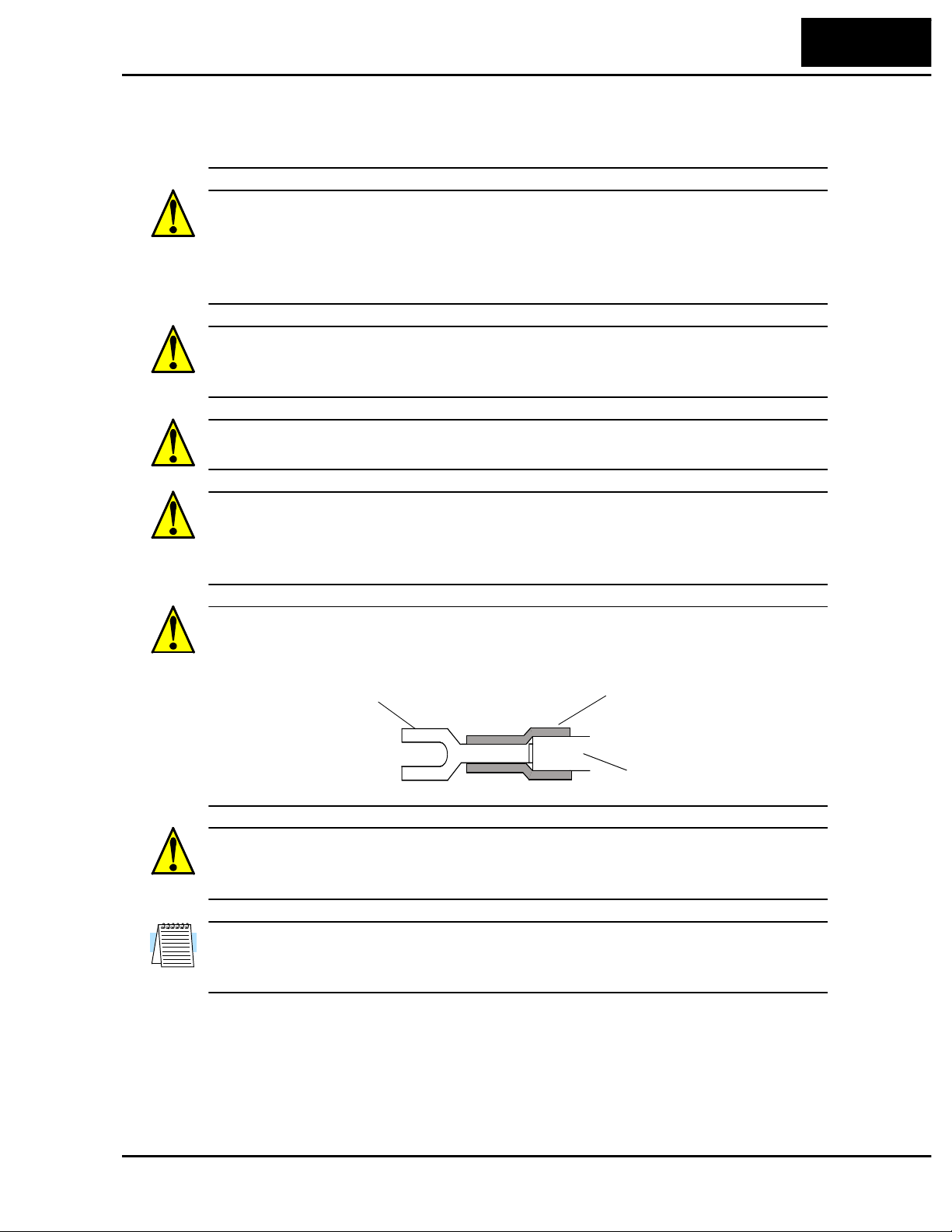
CAUTION: Connection to field wiring terminals must be reliably fixed having two
independent means of mechanical support. Using a termination with cable support
(figure below), or strain relief, cable clamp, etc.
Terminal (spade lug) Cable support
Cable
CAUTION: A double-pole disconnection device must be fitted to the incoming mains
supply close to the inverter. Additionally, a protection device meeting IEC947-1/
IEC947-3 must be fitted at this point (protection device data shown in page 2–13).
NOTE: The above instructions, together with any other requirements are highlighted in
this manual, and must be followed for continued LVD (European Low Voltage Directive)
compliance.
Page 7

iv
Technologies Inc.
Toll Free: voice: 1-877-539-2542 fax: 1-800-539-2542 www.mgitech.com
Precautions for EMC (Electromagnetic Compatibility)
Precautions for EMC (Electromagnetic Compatibility)
You are required to satisfy the EMC directive (89/336/EEC) when using an L100
inv erter in a European country. To satisfy the EMC directive and to comply with
standard, follow the checklist below.
WARNING: This equipment should be installed, adjusted, and serviced by qualified
personal familiar with construction and operation of the equipment and the hazards
involved. Failure to observe this precaution could result in bodily injury.
1. The power supply to L100 inverter must meet these specifications:
a. Voltage fluctuation+/- 10% or less
b. Voltage imbalance +/- 3% or less
c. Frequency variation +/- 4% or less
d. Voltage distortion THD = 10% or less
2. Installation measure:
a. Use a filter designed for L100 inverter
3. Wiring:
a. Shielded wire (screened cable) is required for motor wiring, and the length must
be less than 50 meters.
b. The carrier frequency setting must be less than 5 kHz to satisfy EMC require-
ments.
c. Separate the main circuit from the signal/process circuit wiring.
4. Environmental conditions - when using a filter, follow these guidelines:
a. Ambient temperature: -10 to 40 °C
b. Humidity: 20 to 90% RH (non-condensing)
2
c. Vibration: 5.9 m/sec
d. Location: 1000 meters or less altitude, indoors (no corrosive gas or dust)
(0.6 G) 10 ~ 55Hz
Page 8
L100 Inverter
Technologies Inc.
Toll Free: voice: 1-877-539-2542 fax: 1-800-539-2542 www.mgitech.com
Index to Warnings and Cautions in This Manual
Installation - Cautions for Mounti ng Procedures
v
CAUTION: Be sure to install the unit on flame-resistant material
such as a steel plate. Otherwise, there is the danger of fire.
CAUTION: Be sure not to place any flammable materials near the
inverter. Otherwise, there is the danger of fire.
CA UTION: B e sure not to let the foreign matter enter vent openings
in the inv erter housing, such as wire clippings, spatter from welding,
metal shavings, dust, etc. Otherwise, there is the danger of fire.
CAUTION: Be sure to install the inverter in a place which can bear
the weight according to the specifications in the text (Chapter 1,
Specifications Tables). Otherwise, it may fall and cause injury to personnel.
CA UTION: Be sure to install the unit on a perpendicular w all which
is not subject to vibration. Otherwise, it may fall and cause injury to
personnel.
CAUTION: Be sure not to install or operate an inverter which is
damaged or has missing parts. Otherwise, it may cause injury to personnel.
CAUTION: Be sure to install the inverter in a well-ventilated room
which does not have direct exposure to sunlight, a tendenc y for high
temperature, high humidity or dew condensation, high lev els of dust,
corrosive gas, e xplosive gas, inflammable gas, grinding-fluid mist,
salt damage, etc. Otherwise, there is the danger of fire.
........... 2–6
........... 2–6
........... 2–6
........... 2–6
........... 2–6
........... 2–6
........... 2–6
Wiring - Warnings for Electrical Practices and W ire Specifications
WARNING: “Use 60/75°C Cu wire only” or equivalent. ......... 2–12
WARNING: “Open Type Equipment.” ......... 2–12
WARNING: “A Class 2 circuit wired with Class 1 wire” or equivalent.
WARNING: “Suitable for use on a circuit capable of delivering not
more than 5,000 rms symmetrical amperes, 240 V maximum.” For
models with suffix N or L.
......... 2–12
......... 2–12
Page 9
vi
Technologies Inc.
Toll Free: voice: 1-877-539-2542 fax: 1-800-539-2542 www.mgitech.com
Index to Warnings and Cautions in This Manual
WARNING: “Suitable for use on a circuit capable of delivering not
more than 5,000 rms symmetrical amperes, 240 V maximum.” For
models with suffix N or L.
HIGH VOLTAGE: Be sure to ground the unit. Otherwise, there is a
danger of electric shock and/or fire.
HIGH VOLTAGE: Wiring work shall be carried out only by qualified personnel. Otherwise, there is a danger of electric shock and/or
fire.
HIGH VOLTAGE: Implement wiring after checking that the power
supply is off. You may incur electric shock and/or fire.
HIGH VOLTAGE: Do not connect wiring to an inverter or operate
an inverter that is not mounted according the instructions given in
this manual. Otherwise, there is a danger of electric shock and/or
injury to personnel.
WARNING: Make sure the input power to the inverter is off. If the
drive has been po were d, leave it off for five minutes before continuing.
........ 2–12
........ 2–12
........ 2–12
........ 2–12
........ 2–12
........ 2–16
Wiring - Cautions for Electrical Practices
CAUTION: Be sure that the input voltage matches the inverter
specifications: • Single/Three phase 200 to 240 V 50/60 Hz (up to
2.2kW) • Three phase 200 to 230V 50/60Hz (abo ve 2.2kW) • Th ree
phase 380 to 460 V 50/60Hz
CAUTION: Be sure not to input a single phase to a three-phaseonly type invert er. Otherwise, there is the danger of fire.
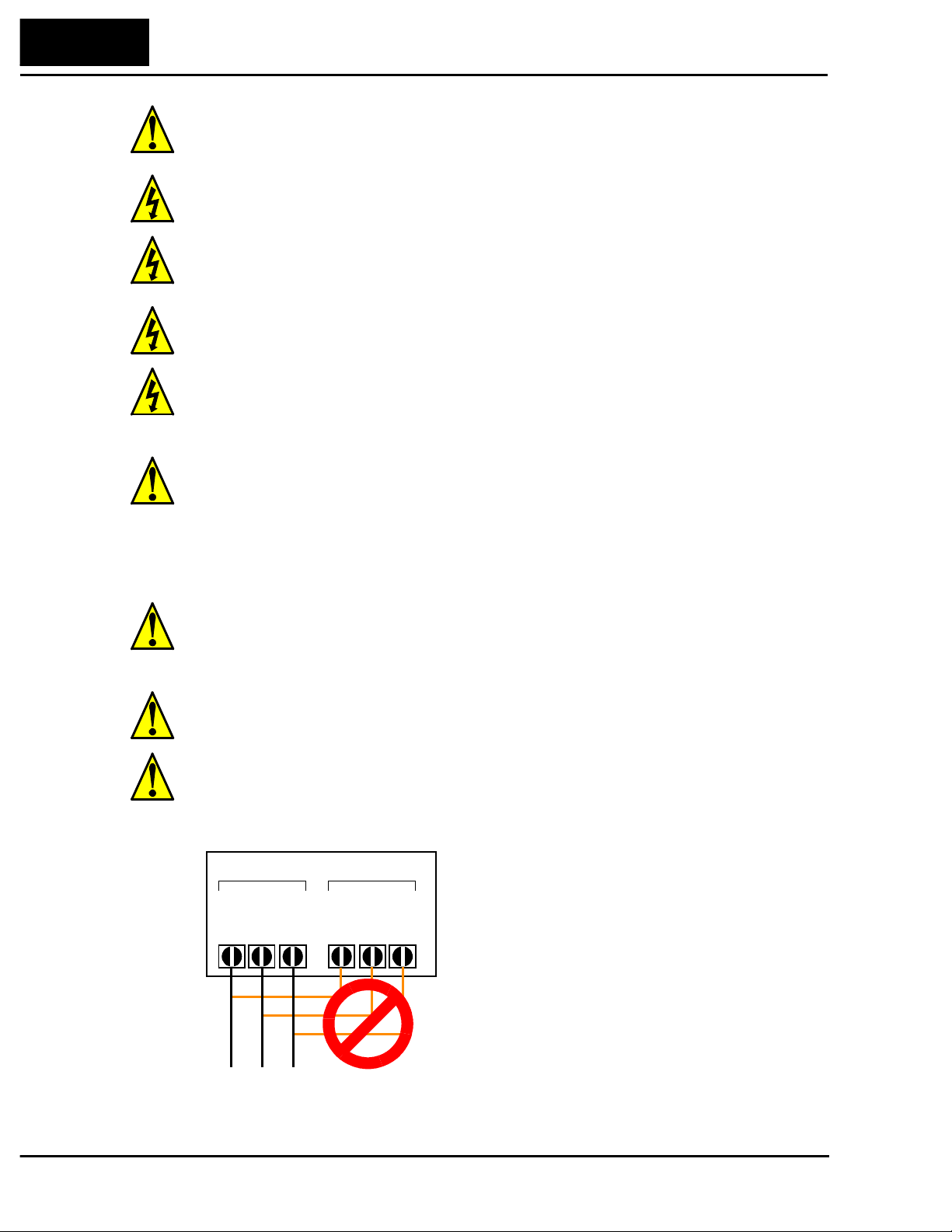
CAUTION: Be sure not to connect an AC power supply to the
output terminals. Otherwise, there is the danger of injury and/or
fire.
Power Input Power Output
(L) (N)
L1 L2 L3
T1 T2 T3
UVW
NOTE:
L, N:
L1, L2, L3:
........ 2–14
........ 2–14
........ 2–14
Single-phase 200 to 240V 50/60 Hz
Three-phase 200 to 240V 50/60 Hz
Three-phase 380 to 460V 50/60 Hz
Page 10
L100 Inverter
Technologies Inc.
Toll Free: voice: 1-877-539-2542 fax: 1-800-539-2542 www.mgitech.com
vii
CA UTION: Fasten the screws with the specified fastening torque
(see the following table). Check for any loosening of scre ws. Otherwise, there is the danger of fire.
CA UTION: Rema rks for using earth leaka ge c ircuit breakers in the
mains supply: Frequency inverters with CE-filters (RFI-filter) and
shielded (screened) motor cables have a higher leakage current
toward Earth GND. Especially at the moment of switching on this
can cause inadvertent tripping of earth leakage circuit breakers.
Because of the rectifier on the input side of the inverter there is the
possibility to stall the switch-off function through small amounts of
DC current. Please observe the following: • Use only short timeinvariant and pulse current-sensitive earth leakage circuit breakers
with higher trigger current. • Other components should be secured
with separate earth leakage circuit breakers. • Earth leakage circuit
breakers in the power input wiring of an inverter are not an absolute
protection against electric shock by direct touching.
CAUTION: Be sure to install a fuse in the wire for each phase of
the main power supply to the inverter. Otherwise, there is the
danger of fire.
CA UTION: For motor leads, earth leakage breakers and electromagnetic contactors, be sure to size these components properly
(each must have the capacity for rated current and voltage). Otherwise, there is the danger of fire.
......... 2–15
......... 2–15
......... 2–15
......... 2–15
Powerup Test Caution Messa ges
CAUTION: The heat sink fins will have a high temperature. Be
careful not to touch them. Otherwise, there is the danger of getting
burned.
CAUTION: The operation of the inverter can be easily changed
from low speed to high speed. Be sure check the capability and
limitations of the motor and machine before operating the inverter.
Otherwise, there is the danger of injury.
CA UTION: If you operate a motor at a frequency higher than the
inve rte r standard def ault setting (50Hz/60Hz), be sure to check the
motor and machine specifications with the re specti v e manufacturer.
Only operate the motor at elevated frequencies after getting their
approval. Otherwise, there is the danger of equipment damage.
CA UTION: Check the following before and during the powerup
test. Otherwise, there is the danger of equipment damage. • Is the
shorting bar between the +1 and + terminals installed? DO NOT
power or operate the inverter if the jumper is removed. • Is the
direction of the motor correct? • Did the inverter trip during acceleration or deceleration? • Were the rpm and frequency meter readings
as expected? • Were there any abnormal motor vibrations or noise?
......... 2–17
......... 2–17
......... 2–18
......... 2–18
Page 11
viii
Technologies Inc.
Toll Free: voice: 1-877-539-2542 fax: 1-800-539-2542 www.mgitech.com
Index to Warnings and Cautions in This Manual
Warnings for Operations and Monitoring
WARNING: Be sure to turn on the input power supply after closing
the front case. While being energized, be sure not to open the front
case. Otherwise, there is the danger of electric shock.
WARNING: Be sure not to operate the switches with wet hands.
Otherwise, there is the danger of electric shock.
WARNING: While the inv erter is ener gized, be sure not to touch
the inverter terminals even when the motor is stopped. Otherwise,
there is the danger of electric shock.
WARNING: If the Retry Mode is selected, the motor may suddenly
restart during the trip stop. Do not approach the machine (be sure to
design the machine so that safety for personnel is secure even if it
restarts.) Otherwise, it may cause injury to personnel.
WARNING: If the power supply is cut off for a s hort period of time,
the inv erter may restart operation after the po wer supply reco ve rs if
the command to operate is active. If a restart may pose danger to
personnel, so be sure to use a lock-out circuit so that it will not
restart after power recovery. Otherwise, it may cause injury to
personnel.
WARNING: The Stop Key is effective only when the Stop function
is enabled. Be sure to enable the Key separately from the
emergency stop. Otherwise, it may cause injury to personnel.
.......... 4–3
.......... 4–3
.......... 4–3
.......... 4–3
.......... 4–3
.......... 4–3
WARNING: After the operation command is given, if the alarm
reset is conducted, it will restart suddenly. Be sure to set the alarm
reset after verifying the operation command is off. Otherwise, it
may cause injury to personnel.
WARNING: Be sure not to touch the inside of the energized
inve rter or to put any conductive object into it. Otherwise, there is a
danger of electric shock and/or fire.
WARNING: When the power is turned on when the running
command is already active, the motor will suddenly start rotation
and is dangerous. Before turning the power on, confirm that the
running command is not enabled.
WARNING: When the Stop key function is disabled, pressing the
Stop key does not cancel the stop and trip.
WARNING: Be sure to provide a separate, hard-wired emergency
stop switch. When the operation command source is a digital operator, this selection is ineffective.
WARNING: If the power is turned on and the Run command is
already active, the motor starts rotation and is dangerous! Before
turning power on, confirm that the Run command is not active.
.......... 4–3
.......... 4–3
.......... 4–3
.......... 4–3
.......... 4–3
.......... 4–6
Page 12
L100 Inverter
Technologies Inc.
Toll Free: voice: 1-877-539-2542 fax: 1-800-539-2542 www.mgitech.com
ix
WARNING: After the Reset command is given and the alarm reset
occurs, the motor will restart suddenly if the Run command is
already active. Be sure to set the alarm reset after verifying that the
Run command is off to prevent injury to personnel.
Cautions for Operations and Monitoring
CAUTION: The heat sink fins will have a high temperature. Be
careful not to touch them. Otherwise, there is the danger of getting
burned.
CAUTION: The operation of the inverter can be easily changed
from low speed to high speed. Be sure check the capability and
limitations of the motor and machine before operating the inverter.
Otherwise, it may cause injury to personnel.
CA UTION: If you operate a motor at a frequency higher than the
inve rte r standard def ault setting (50Hz/60Hz), be sure to check the
motor and machine specifications with the re specti v e manufacturer.
Only operate the motor at elevated frequencies after getting their
approval. Otherwise, there is the danger of equipment damage.
CA UTION: It is possible to da mage the inverter or other devices in
your application if the maximum current or voltage characteristics
of a connection point are exceeded.
......... 4–16
........... 4 –2
........... 4 –2
........... 4 –2
........... 4 –4
Warnings and Cautions for Troubleshooting and Maintenance
WARNING: Wait at least fiv e (5) minutes after turning of f the input
power supply before performing maintenance or an inspection.
Otherwise, there is the danger of electric shock.
WARNING: Make sure that only qualified personnel will perform
maintenance, inspection, and part replacement. (Before starting to
work, remove any metallic objects from your person (wristwatch,
bracelet, etc.). Be sure to use tools with insulated handles. Otherwise, there is a danger of electric shock and/or injury to personnel.
WARNING: Neve r remo ve connectors by pulling on its wire leads
(wires for cooling fan and logic p.c.board). Otherwise, there is a
danger of fire or injury due to wire breakage.
CA UTION: When removing connectors, nev er pull the wires (wires
for the cooling fan and logic P.C. board. Otherwise, there is danger
of fire due to wire breakage and/or injury to personnel.
CAUTION: Never test the withstand voltage (HIPOT ) on the
inve rter. The inv erter has a sur ge protector be tween the ma in circuit
terminals above and the chassis ground.
........... 6 –2
........... 6 –2
........... 6 –2
........... 6 –2
......... 6–12
Page 13
x
Technologies Inc.
Toll Free: voice: 1-877-539-2542 fax: 1-800-539-2542 www.mgitech.com
General Warnings and Cautions
HIGH VOLTAGE: Be careful not to touch wiring or connector
terminals when working with the inverters and taking measurements. Be sure to place the measurement circuitry above in an
insulated housing before using them.
General Warnings and Cautions
WARNING: Never modify the unit. Otherwise, there is a danger of electric shock and/
or injury.
CAUTION: Withstand voltage tests and insulation resistance tests (HIPOT) are
executed before the units are shipped, so there is no need to conduct these tests before
operation.
CAUTION: Do not attach or remove wiring or connectors when po wer is applied. Also,
do not check signals during operation.
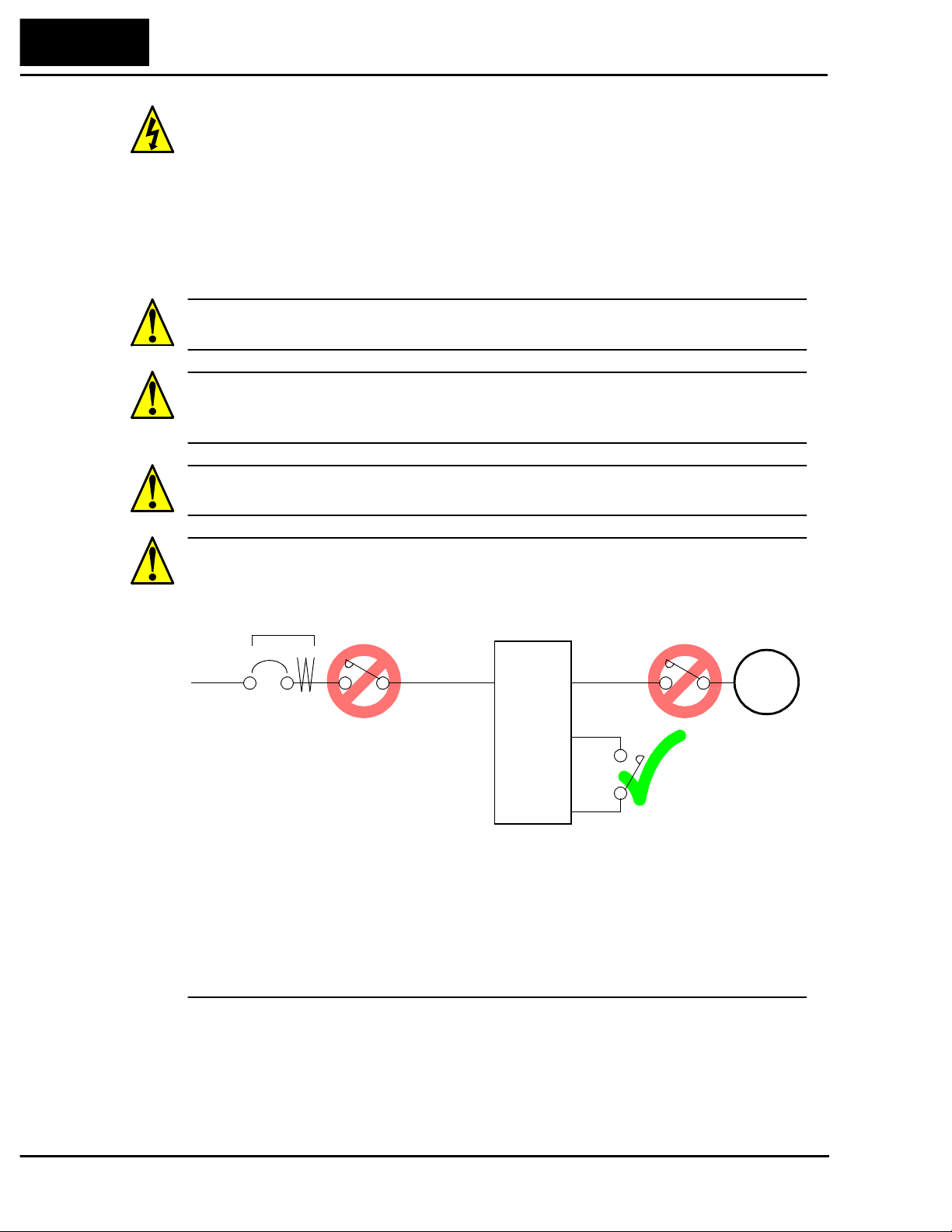
CAUTION: Do not stop operation by switching off electromagnetic contactors on the
primary or secondary sides of the inverter.
........ 6–13
Earth leakage
breaker
Power
Input
When there has been a sudden power f ailure while an operation instruction is acti ve, then
the unit may restart operation automatically after the power f ailure has ended. If there is
a possibility that such an occurrence may harm humans, then install an electromagnetic
contactor (Mgo) on the power supply side, so that the circuit does not allow automatic
restarting after the power supply recovers. If the optional remote operator is used and
the retry function has been selected, this will also cause automatic restarting when an
operation instruction is active. So, please be careful.
L1, L2, L3
Inverter
U, V, W
Motor
P24
FW
Page 14
L100 Inverter
Technologies Inc.
Toll Free: voice: 1-877-539-2542 fax: 1-800-539-2542 www.mgitech.com
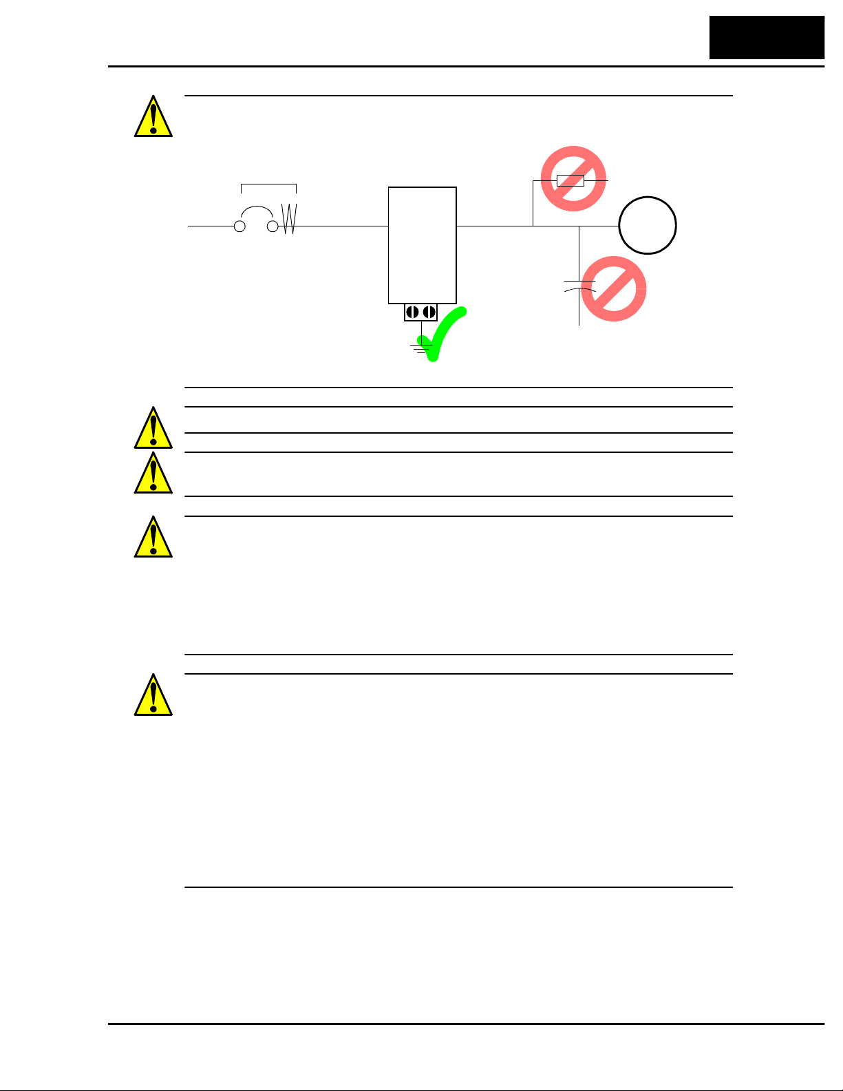
CAUTION: Do not insert leading power factor capacitors or surge absorbers between
the output terminals of the inverter and motor.
xi
Earth leakage
breaker
Surge absorbe r
Power
Input
L1, L2, L3
U, V, W
Motor
Inverter
Leading power
GND lug
factor capacitor
CAUTION: Be sure to connect the grounding terminal to earth ground.
CAUTION: When inspecting the unit, be sure to wait five minutes after tuning off the
power supply before opening the cover.
CAUTION: MOTOR TERMINAL SURGE VOLTAGE SUPPRESSION FILTER
(For the 400 V CLASS)
In a system using an inv er ter with the voltage control PWM system, a voltage surge
caused by the cable constants such as the cable length (especially when the distance
between the motor and inverter is 10 m or more) and cabling method may occur at the
motor terminals. A dedicated filter of the 400 V class for suppressing this voltage surge
is available. Be sure to install a filter in this situation.
CAUTION: SUPPRESSION FOR NOISE INTERFERENCE FROM INVERTER
The inve rter uses many semiconductor switching elements such as transistor s and
IGBTs. Thus, a radio receiver or measuring instrument located near the inverter is
susceptible to noise interference.
To protect the instruments from erroneous operation due to noise interference, they
should be used well away from the inverter. It is also effective to shield the whole
inverter structure.
The addition of an EMI filter on the input side of the inverter also reduces the effect of
noise from the commercial power line on external devices.
Note that the external dispersion of noise from the power line can be minimized by
connecting an EMI filter on the primary side of inverter.
Page 15
xii
Technologies Inc.
Toll Free: voice: 1-877-539-2542 fax: 1-800-539-2542 www.mgitech.com
General Warnings and Cautions
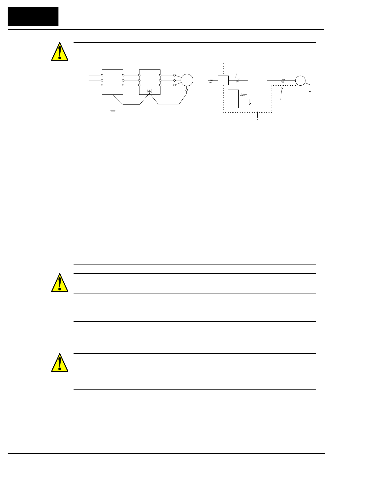
CA UTION: EFFECTS OF DISTRIBUTOR LI NES ON INVERTERS
Power
source
EMI filter Inverter
R1
R2
S1
S2
T1
T2
L1(L1)
L2
L3(N)
Motor
U
U
V
V
W
W
Power
source
Terminal
for
grounding
EMI
filter
Noise
Inverter
Ground the
frame.
Remote
operator
Noise
Completely ground the shield made
of metal screen, enclosed panel, etc.
with as short a wire as possible.
Piping
(to be grounded)
or shielded wire
Motor
In the cases belo w in v o lving a general-purpos e inverter, a lar ge peak current fl ows on the
power supply side, sometimes destroying the converter module. Where such situations
are foreseen, or the paired equipment must be highly reliable, install an AC reactor
between the power supply and the inverter.
1. The unbalance factor of the power supply is 3% or higher.
2. The power supply capacity is at least 10 times greater than the inverter capacity (and
the power supply capacity, 500 kVA or more).
3. Abrupt power supply changes are expected.
Some examples include:
a.Several inverters are interconnected with a short bus.
b.A thyristor converter and an inverter are interconnected with a short bus.
c:An installed phase advance capacitor opens and closes.
In cases (1), (2), and (3) we recommend installing an AC reactor of 3% (at a voltage
drop at rated current) with respect to the supply voltage on the power supply side.
CAUTION: When the EEPROM error E8 occurs, be sure to confirm the setting value
again.
CAUTION: When setting b contact to the forward or reverse command [FW], [RV]
terminal, the inverter starts automatica lly. Do not set to b contact without a purpose.
General Caution
CAUTION: In all the illustrations in this manual, covers and safety devices are
occasionally removed to describe the details. While operating the product, make sure
that the covers and safety devices are placed as they were specified originally and
operate it according to the instruction manual.
Page 16

Revisions
Technologies Inc.
Toll Free: voice: 1-877-539-2542 fax: 1-800-539-2542 www.mgitech.com
Revision History Table
L100 Inverter
xvii
No. Revision Comments Date of Issue
Initial Release of Manual NB576X May 1999 NB576X
1 Revision A
Pages 1-4 – Specs tables: added row for input curent,
changed rated input voltage tolerance, corrected dynamic
braking %torque, corrected product weight (lbs)
Page 2-8 – Corrected H dimension for -002 models
August 1999 NB576XA
Operation
Manual No.
Page 17

Technologies Inc.
Toll Free: voice: 1-877-539-2542 fax: 1-800-539-2542 www.mgitech.com
Page 18

Getting Started
Technologies Inc.
Toll Free: voice: 1-877-539-2542 fax: 1-800-539-2542 www.mgitech.com
1
In This Chapter.... page
— Introduction ...................................................... 2
— L100 Inverter Specifications............................. 4
— Introduction to Variable-Frequency Drives....... 7
— Frequently Asked Questions.......................... 12
Page 19
1–2
Technologies Inc.
Toll Free: voice: 1-877-539-2542 fax: 1-800-539-2542 www.mgitech.com
Getting S tarted
Introduction
Introduction
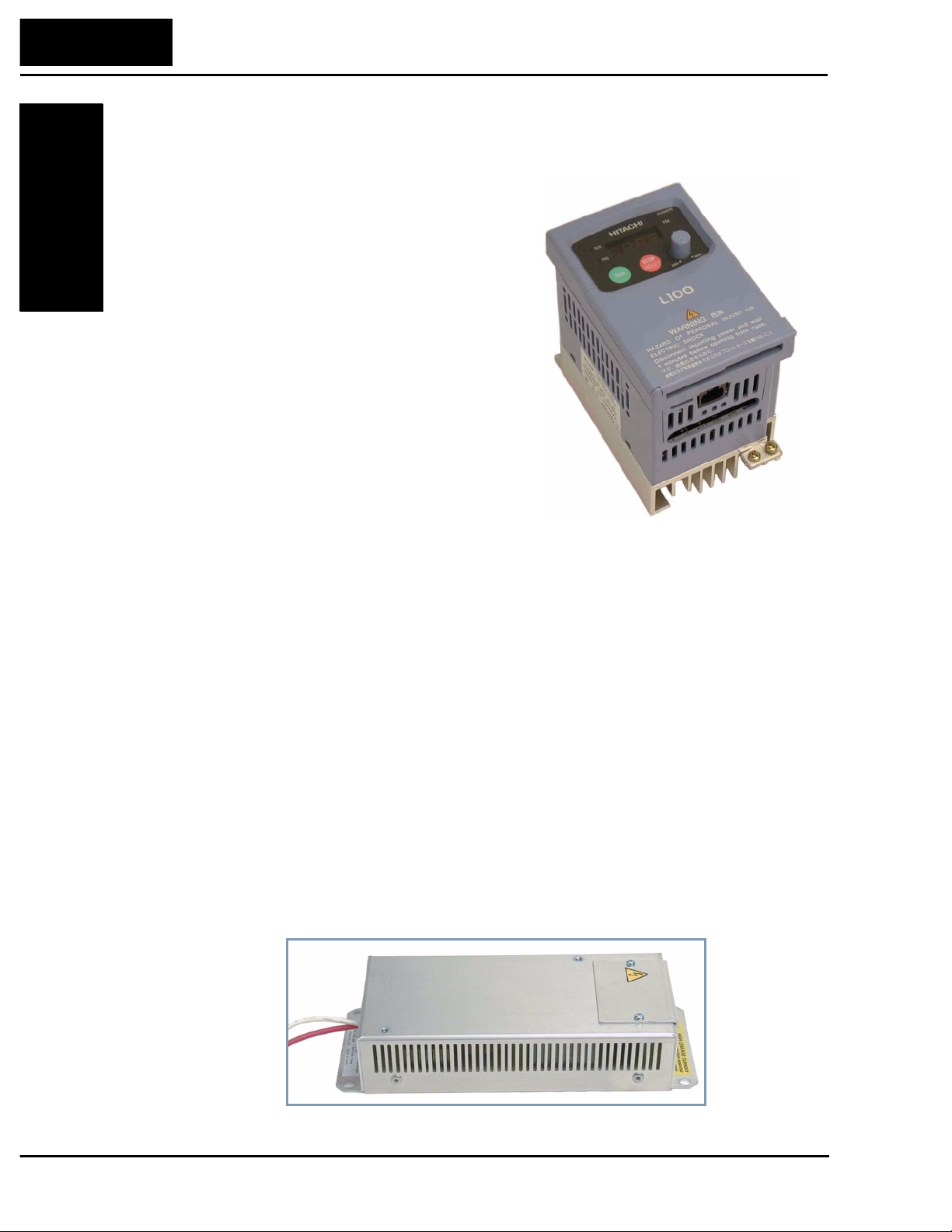
Main Features
Congratulations on your purchase of an L100
Series Hitachi inverter! This inverter drive
features state-of-the-art circuitry and components
to provide high performance. The housing
footprint is exceptionally small, given the size of
the corresponding motor. The Hitachi L100
product line includes more than a dozen inverter
models to cover motor sizes from 1/4 horsepo wer
to 10 horsepower, in either 230 VAC or 460 VAC
power input versions. The main features are:
• Convenient keypad for parameter settings
• Built-in RS-422 communications interface to
allow configuration from a PC and for f ield bus
external modules.
• Sixteen programmable speed levels
• Two-step acceleration and deceleration curves
• PID control adjusts motor speed automatically to maintain a process variable value
The design in Hitachi inverters overcomes many of the traditional trade-offs between
speed, torque and efficiency. The per formance characteristics are:
• V/F (volts-per-hertz) control algorithm, selectable for either constant or reduced
torque loads
• Output frequency range from 0.5 to 360 Hz
• Continuous torque operation at 100% within a 1:10 speed range (6/60 Hz / 5/50 Hz)
without motor derating
A full line of accessories from Hitachi is available to complete your application:
• Digital remote operator keypad
• Dynamic braking unit
• Radio noise filters and EMI filters (shown below)
• CE compliance filters
• DIN rail mounting adapter (35mm rail size)
Model L100-002NFU
EMI Filter
Page 20
Inverter Specifications Label
Technologies Inc.
Toll Free: voice: 1-877-539-2542 fax: 1-800-539-2542 www.mgitech.com
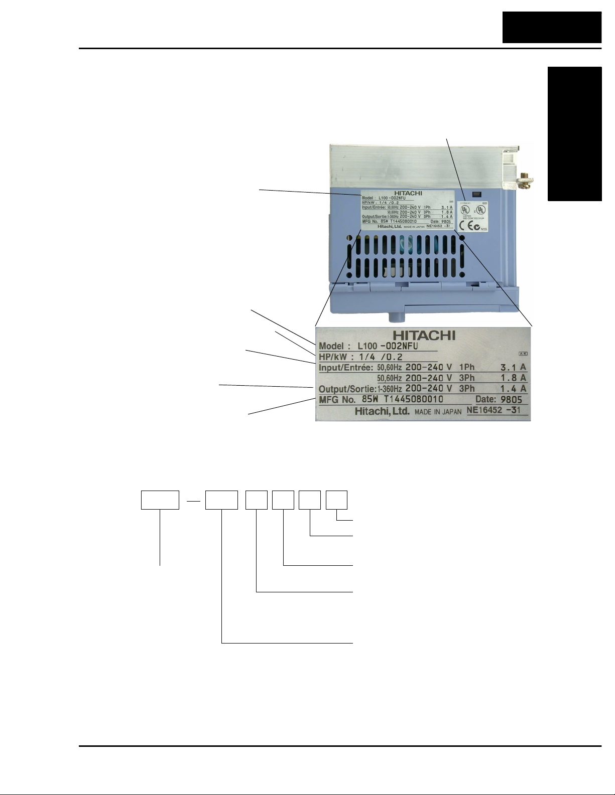
The Hitachi L100 inverters have product labe ls located on the right side of the housing,
as pictured below. Be sure to verify that the specifications on the labels match your
power source, motor, and application safety requirements.
Specifications label
Inv erter model number
L100 Inverter
1–3
Getting Started
Regulatory agency approvals
Motor capacity for this model
Power Input Rating:
frequency, voltage, phase, current
Output Rating:
Frequency, voltage, current
Manufacturing codes:
Lot number, date, etc.
Model Number Convention
The model number for a specific in verter contains useful information about its operating
characteristics. Refer to the model number legend below:
L100 004 H F U 5
Series name
Version number (_, 1, 2, ...)
Restricted distribution:
E=Europe, U=USA
Configuration type
F = with digital operator (keypad)
Input voltage:
N = single or three-phase 200V class
H = three-phase 400V class
L = three phase only, 200V class
Applicable motor capacity in kW
001 = 0.1 kW
002 = 0.2 kW
004 = 0.4 kW
005 = 0.55 kW
007 = 0.75 kW
011 = 1.1 kW
015 = 1.5 kW
022 = 2.2 kW
030 = 3.0 kW
037 = 3.7 kW
040 = 4.0 kW
055 = 5.5 kW
075 = 7.5 kW
Page 21
1–4
Technologies Inc.
Toll Free: voice: 1-877-539-2542 fax: 1-800-539-2542 www.mgitech.com
L100 Inverter Specifications
L100 Inverter Specifications
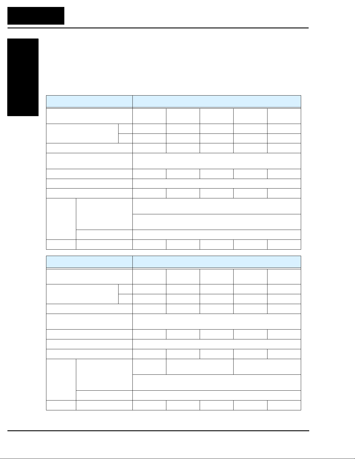
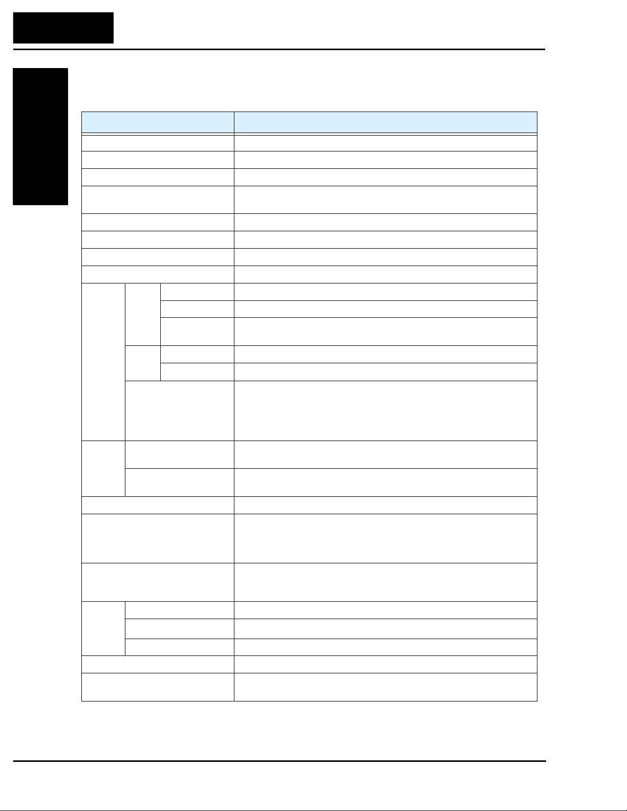
Model-specific tables for 200V and 400V class inverters
The following three tables are specific to L100 in verters for the 200V and 400V class
model groups. The table on page 1–6 gives the general specificat ions that apply to both
voltage class groups. Footnotes for all specifications tables are on the next page.
Getting S tarted
L100 inverters, 200V models 002NFE
Applicable motor size *2 kW 0.2 0.4 0.55 0.75 1.1
Rated capacity (240V) kVA *10 0.5 1.0 1.2 1.6 2.0
Rated input voltage 1-phase: 200 to 240V +5%/-10%, 3-phase: 200 to 230V ±10%,
Rated input current (A), (1-ph / 3-ph) 3.1 / 1.8 5.8 / 3.4 6.7 / 3.9 9.0 / 5.2 11.2 / 6.5
Rated output voltage *3 3-phase 200 to 240V (corresponding to input voltage)
Rated output current (A) 1.4 2.6 3.0 4.0 5.0
Braking Dynamic braking,
Weight kg / lb 0.8 / 1.9 0.8 / 1.9 1.3 / 2.9 1.3 / 2.9 2.2 / 4.8
Item 200V Class Specifications
004NFE
002NFU
HP 1/4 1/2 3/4 1 1 1/2
50/60 Hz ±5% (037LFU, 055LFU & 075LFU 3-phase only)
approx. % torque,
(short time, stopping
from 50 / 60 Hz) *5
DC braking Variable operating frequency, time, and braking force
Capacitive feedback type, dynamic braking unit and braking resistor
optional, individually installed
004NFU
005NFE
—
100%: ≤ 50Hz,
50%: ≤ 60 Hz
007NFE
007NFU
011NFE
—
Item 200V Class Specifications, continued
L100 inverters, 200V models 015NFE
015NFU
Applicable motor size *2 kW 1.5 2.2 3.7 5.5 7.5
HP2357.510
Rated capacity (240V) kVA *10 2.9 4.1 6.3 9.6 12.7
Rated input voltage 1-phase: 200 to 240V ±10%, 3-phase: 200 to 230V ±10%,
50/60 Hz ±5% (037LFU, 055LFU & 075LFU 3-phase only)
Rated input current (A), (1-ph / 3-ph) 16.0 / 9.3 22.5 / 13.0 – / 20.0 – / 30.0 – / 40.0
Rated output voltage *3 3-phase 200 to 240V (corresponding to input voltage)
Rated output current (A) 7.1 10.0 15.9 24 32
Braking Dynamic braking,
approx. % torque,
(short time, stopping
from 50 / 60 Hz) *5
DC braking Variable operating frequency, time, and braking force
Weight kg / lb 2.2 / 4.8 2.8 / 6.2 2.8 / 6.2 5.5 / 12.1 5.7 / 12.6
100%: ≤ 50Hz
50%: ≤ 60Hz
Capacitive feedback type, dynamic braking unit and braking resistor
optional, individually installed
022NFE
022NFU
40%: ≤ 50Hz
20%: ≤ 60Hz
—
037LFU
—
055LFU
20%: ≤ 50Hz
20%: ≤ 60Hz
—
075LFU
Page 22
L100 Inverter
Technologies Inc.
Toll Free: voice: 1-877-539-2542 fax: 1-800-539-2542 www.mgitech.com
1–5
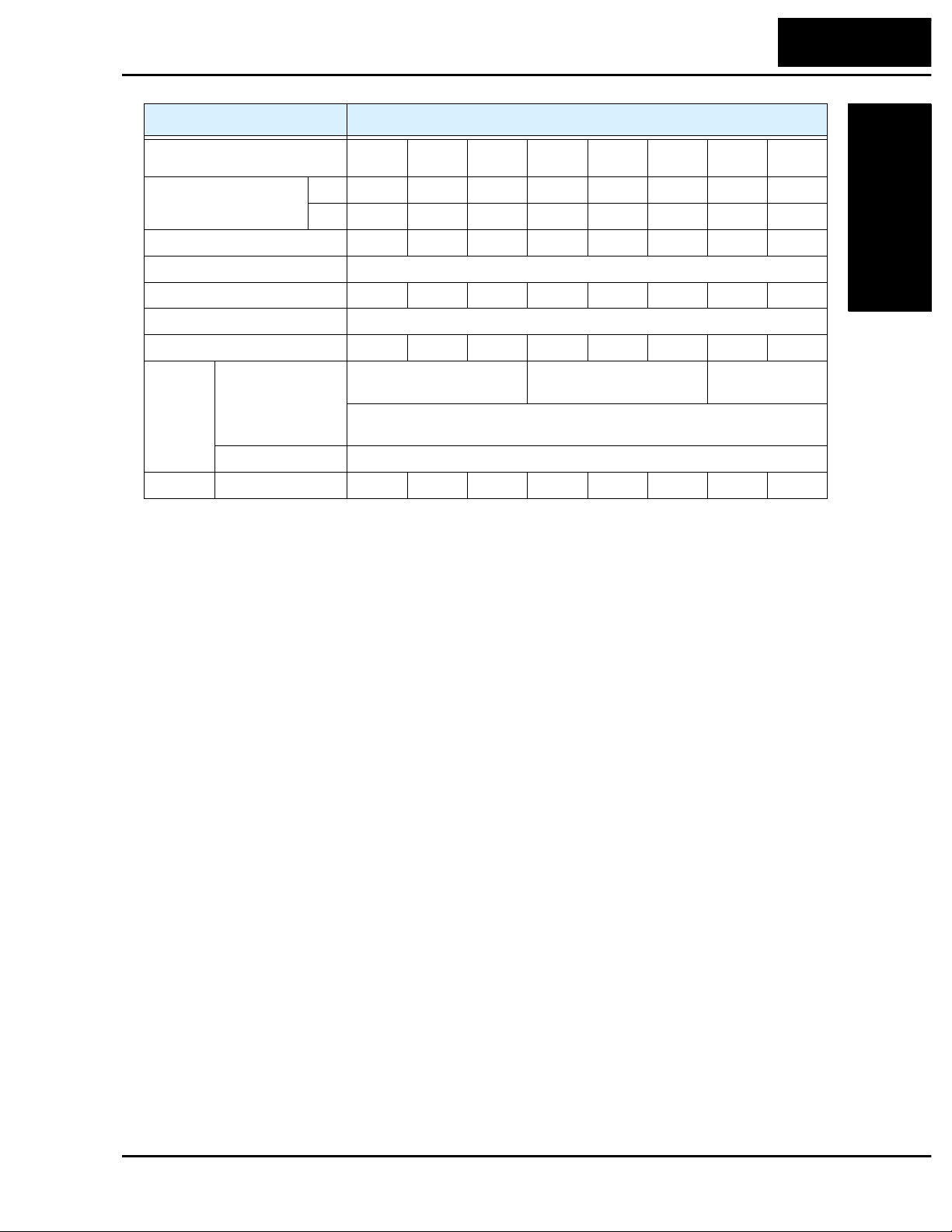
Item 400V Class Specifications
L100 inverters, 400V models
Applicable motor size *2 kW 0.4 0.75 1.5 2.2 3 .0 4.0 5.5 7.5
Rated capacity (460V) kVA *10 1.1 1.9 3.0 4.3 6.2 6.8 10.4 12.7
Rated input voltage 3-phase: 380 to 460V ±10%, 50/60 Hz ±5%
Rated input current (A) 2.0 3.3 5.0 7.0 10.0 11.0 16.5 20.0
Rated output voltage *3 3-phase: 380 to 460V (corresponding to input voltage)
Rated output current (A) 1.5 2.5 3.8 5.5 7.8 8.6 13 16
Braking Dynamic braking,
approx. % torque,
(short time, stopping
from 50 / 60 Hz) *5
DC braking Variable operating frequency , time, and braking force
Weight kg / lb 1.3/2.9 1.7/3.7 1.7/3.7 2.8/6.2 2.8/6.2 2.8/6.2 5.5/12.1 5.7/12.5
004HFE
004HFU
HP1/2123457.510
Capacitive feedback type, dynamic braking unit and braking resistor optional,
individually installed
007HFE
007HFU
100%: ≤ 50Hz
50%: ≤ 60Hz
015HFE
015HFU
022HFE
022HFU
030HFE—040HFE
40%: ≤ 50Hz,
20%: ≤ 60Hz
040HFU
055HFE
055HFU
20%: ≤ 50Hz
20%: ≤ 60Hz
075HFE
075HFU
Footnotes for the preceding tables and the table on the following page:
*1: The protection method conforms to JEM 1030.
*2: The applicable motor refers to Hitachi standard 3-phase motor (4-pole). To use other
motors, care must be taken to prevent the rated motor current (50/60 Hz) from exceeding the
rated output current of the inverter.
*3: The output voltage decreases as the main supply voltage decreases (except for use of the
AVR function). In any case, the output voltage cannot exceed the input power supply
voltage.
*4: To operate the motor beyond 50/60 Hz, consult the motor manufacturer about the maximum
allowable rotation speed.
*5: The braking torque via capacitive feedback is the average deceleration torque at the shortest
deceleration (stopping from 50/60 Hz as indicated). It is not continuous regenerative braking
torque. And, the average deceleration torque varies with motor loss. This value decreases
when operating beyond 50 Hz. Note that a braking unit is not included in the inverter. If a
large regenerative torque is required, the optional regenerative braking unit should be used.
*6: The frequency command is the maximum frequency at 9.8V for input voltage 0 to 10 VDC,
or at 19.6 mA for input current 4 to 20 mA. If this characteristic is not convenient for your
application, contact your Hitachi sales representative.
*7: If operating the inverter in an ambient temperature of 40–50
to 2.1 kHz, derate the output current by 80%, and remove the top housing cover. Note that
removing the top cover will nullify the NEMA rating for the inverter housing.
*8: The storage temperature refers to the short-term temperature during transport.
*9: Conforms to the test method specified in JIS C0911 (1984). For the model types excluded in
the standard specifications, contact your Hitachi sales representative .
*10:The input voltage of xxLFU is 230V.
C, reduce the carrier frequency
°
Getting Started
Page 23
1–6
Technologies Inc.
Toll Free: voice: 1-877-539-2542 fax: 1-800-539-2542 www.mgitech.com
Getting S tarted
L100 Inverter Specifications
General Specifications
The following table applies to all L100 i nverters.
Item General Specifications
Protective housing *1 IP20
Control method Sine wave pulse-width modulation (PWM) control
Output frequency range *4 0.5 to 360 Hz
Frequency accuracy Digital command: 0.01% of the maximum frequency
Analog command: ±0.2% of the maximum frequency (25°C ± 10°C)
Frequency setting resolution Digital: 0.1 Hz; Analog: max. frequency/1000
Volt./Freq. characteristic V/F optionally variable, V/F control (constant torque, reduced torque)
Overload current rating 150%, 60 seconds
Acceleration/deceleration time 0.1 to 3000 sec., (linear accel/decel), second accel/decel setting available
Input
signal
Output
signal
Alarm output contact ON for inverter alarm (1C contacts, both normally open or closed avail.)
Other functions AVR function, curved accel/decel profile, upper and lower limiters, 16-stage
Protective function Over-current, over-voltage, under-voltage, overload, extreme high/low
Operating
Environment
Coating color L ight purple, cooling fins in base color of aluminum
Options Remote operator unit, copy unit, cables for the units, dynamic braking unit,
Freq.
setting
FWD/
REV
Run
Intelligent input
terminal
Intelligent output terminal RUN (run status signal), FA1,2 (frequency arrival signal), OL (ove rload
Frequency monitor PWM output; Select analog output frequency m onitor, analog output current
Ambient storage humidity -10 to 50°C (*7) / -25 to 70°C (*8) / 20 to 90% humidity (non-condensing)
Vibration *9
Location Altitude 1,000 m or less, indoors (no corrosive gasses or dust)
Operator panel
Potentiometer
External signal *6
Operator panel
External signal
Up and Down keys / Value settings
Analog setting
0 to 10 VDC (input impedance 10k Ohms), 4 to 20 mA (input impedance
250 Ohms), Potentiometer (1k to 2k Ohms, 2W)
Run/Stop (Forward/Reverse run change by command)
Forward run/stop, Reverse run/stop
FW (forward run command), RV (reverse run command), CF1~CF4 (multi-
stage speed setting), JG (jog command), 2CH (2-stage accel./decel.
command), FRS (free run stop command), EXT (external trip), USP (startup
function), SFT (soft lock), AT (analog current input select signal), RS (reset),
PTC (thermal protection)
advance notice signal), OD (PID error deviation signal), AL (alarm signal)
monitor or digital output frequency monitor
speed profile, fine adjustment of start frequency, carrier frequency change
(0.5 to 16 kHz) frequency jump, gain and bias setting, process jogging,
electronic thermal leve l adjustment, retry function, trip history monitor
temperature, CPU error, memory error, ground fault detection at startup,
internal communication error, electronic thermal
2
5.9 m/s
braking resistor, AC reactor, DC reactor, noise fil ter, DIN rail mounting
(0.6G), 10 to 55 Hz
Page 24

L100 Inverter
Technologies Inc.
Toll Free: voice: 1-877-539-2542 fax: 1-800-539-2542 www.mgitech.com
1–7
Introduction to Variable-Frequency Drives
The Purpose of Motor Speed Control for Industry
Hitachi inv erters pro vide spee d control for 3-phase AC induction motors. You connect
AC po w er to the inverter, and connect the inverter to the motor. You’re probably familiar
with the way a light dimmer works to vary the power sent to a light bulb, and thus the
light intensity. At a basic le vel, the modern inv erter serves the same role for a motor.
Many industrial applications use AC motors of all sizes to do many different things. In
some cases, the motor connects directly to an AC power source — running at full speed
whenever it is on. Ho we ver, many applications benefit from a motor with variable speed,
in several ways:
• Energy savings - HVAC
• Need to coordinate speed with an adjacent process - textiles and printing presses
• Sensitive loads - eleva t ors, food processing, pharmaceutica ls
Over the years, industry has f ound many ways to achieve variable speed when it
benefited the process. Solutions varied from mechanical (belts and gears), hydraulic
(pumps and motors), and electrical (two-speed motor windings, etc.) While these
solutions provided some control over speed, there were unwanted side effects as well:
• Wasted energy from losses in speed-adjusting mechanisms (gearboxes, etc.)
Getting Started
• Wasted energy from on/off control trying to approximate an average
• Noise from belts and gears or start/stop operations
• Messy machinery with fluid leaks
• High maintenance and/or unreliable components
• Could set the speed, but acceleration and deceleration wa s still uncontrollable
• Not enough speed lev els
• Poor torque performance at low speeds
Most of the unwanted side effects came from mechanical or hydraulic machinery, and
could be solved with a purely electronic solution. But early electronic components had
reliability shortcomings due to the large currents and high voltages imposed on the
devices. Ho wever, the modern power components in use today have changed all that.
The state-of-the-art components in Hitachi drives provide all the benefits of speed
control, while overcoming the classical problems listed above.
What is an Inverter?
The term inverter and variable-frequency drive are related and somewhat interchange-
able. An electronic motor drive for an AC motor can control the motor’s speed by
varying the frequency of the power sent to the motor. F or example, a particular motor
may be designed for 60 Hz operation. We say it is a synchronous motor if its speed of
revolution is directly related to its power input frequenc y. When the motor design is
synchronous, a variable frequency drive is able to control the speed by controlling the
frequency.
Page 25
1–8
Technologies Inc.
Toll Free: voice: 1-877-539-2542 fax: 1-800-539-2542 www.mgitech.com
Getting S tarted
Introduction to Variable-Frequency Drives
An inve rter, in general, is a device that converts DC power to AC po wer. The popular
consumer power inverter is designed for powering an AC appliance from a car battery;
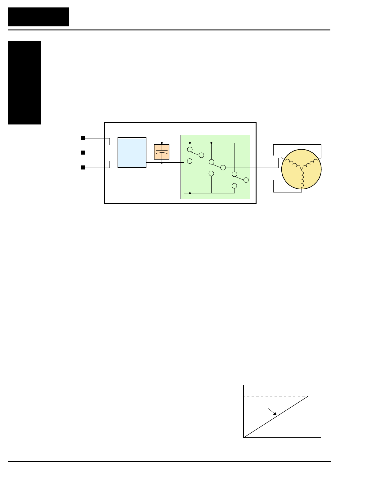
put 12VDC in, and get 115VAC 50/60 Hz out, for example. The figure below sho ws ho w
the variable-frequency drive employes an internal inverter. The dri ve first converts
incoming AC po wer to DC through a rectifier c ircuit, creating a high-v oltage internal DC
bus. Then the inv e rter circuit inverts the DC back to AC again to power the motor.
However, this special inverter varies its output frequency and voltage according to the
desired motor speed.
Power
Input
L1
L2
L3
Converter
Rectifier
Variable-frequency Drive
High-voltage
DC Bus
Inverter
+
+
Motor
U/T1
V/T2
W/T3
–
The simplified drawing of the inverter shows three double-throw swit ches. Usually
implemented with six power transistors, outputs U/T1, V/T2, and W/T3 may switch
positively or neg ati vely. Using a commutation algorithm, the microprocessor in the drive
switches the power transistors on and of f at a very high speed to create the desired output
waveforms. The reactance of the motor windings helps smooth out the pulses.
Torque and Constant Volts/Hertz Operation
In working with industrial motors we often discuss the motor torque. That is simply the
rotational force the motor exerts at any given time. The goal of the inverter is to control
motor speed, but the L100 inverter only has direct control over the output frequenc y and
voltage. The no-load speed will be equal to the inverter output frequency minus a small
amount of slip in the motor (slip is the difference between theoretical motor speed and
actual speed). As the load increases, the slip and the delivered torque also increase . If
the inve rter can create strong motor torque over most or all of the speed range, then it is
relatively easy for the system to achieve any desired speed. Speed regulation is a
measure of the accuracy speed control, given as a percent difference from a fixed value.
The L100 delivers speed regulation (no load to full load) within 3% of the (full scale)
motor nameplate speed value.
When varying the output frequency, the inverter
drive also must vary the output voltage in proportion to the frequency. It does so because of the
motor’s characteristic inductive reactance. If the
drive maintains a constant volts-per -hertz ratio, the
motor will have constant torque characteristics.
Constant torque is desirable for most applications,
because it transfers power to the load consistently
across the entire speed range.
Output
voltage
V
100%
0
Constant torque
Output frequency
f
100%
Page 26

In verter Input and Three-Phase Power
Technologies Inc.
Toll Free: voice: 1-877-539-2542 fax: 1-800-539-2542 www.mgitech.com
Heavy industrial machinery often needs the additional power available from higher
voltage/current sources, and from three-phase power. The Hitachi L100 Series of inve rters includes two sub-groups: the 200V class and the 400V class inverters. The drives
described in this manual may be used in either the United States or Europe, although the
exact voltage level for commercial power may be slightly different from country to
country. Accordingly, a 200V class in verter requires (nominal) 200 to 240VAC , and a
400V class inv erter requires from 380 to 460VAC. Some 200V class inverters will accept
single-phase or three-phase power, but all 400V class inverters require a three-phase
power supply.
The common terminology for single phase power is Line (L) and Neutral (N). Threephase power connections are usually labeled Line 1 (L1), Line 2 (L2) and Line 2 (L3). In
any case, the power source should include an earth ground connection. That ground
connection will need to connect to the inverter chassis and to the motor frame (description given on page 2–16).
Inverter Output to the Motor
L100 Inverter
1–9
Getting Started
The AC motors also use three-phase power, but they
must connect only to the in verter’s output terminals. The
output terminals are uniquely labeled (to differentiate
them from the input terminals) with the designations U/
T1, V/T2, and W/T3. This corresponds to typical motor
lead connection designations T1, T2, and T3. It is
generally not critical to connect a particular inverter
output to a particular motor lead for a new application.
The consequence of swapping any two of the three
connections is the reversal of the motor direction. For
safety reasons, you must connect the motor chassis
ground to the ground connection at the bottom of the inverter housing.
Notice the three connections to the motor do not include one marked “Neutral” or
“Return.” The motor represents a balanced “Y” impedance to the inverter, so there is no
need for a separate return. In other words, each of the three “Hot” connections serves
also as a return for the other connections, because of their phase relationship.
The Hitachi inverter is a rugged and reliable device. The intention is for the inverter to
assume the role of switching power to the motor during all normal operations. Therefore,
this manual instructs you not to switch off power to the inverter while the motor is
running (unless it is an emergency stop). Also, do not install or use cut-off switches in
the wiring from the inverter to the motor (except thermal cut-off). Of course, safetyrelated devices such as fuses must be in the design to break power during a malfunction.
U/T1
3-Phase
AC Motor
V/T2
Earth
GND
W/T3
Page 27
1–10
Technologies Inc.
Toll Free: voice: 1-877-539-2542 fax: 1-800-539-2542 www.mgitech.com
Intelligent Functions and Parameters
Getting S tarted
Introduction to Variable-Frequency Drives
Much of this manual is devoted to describing
how to use inverter functions and how to configure inv erter parameters. The inverter is microprocessor-controlled, and has many independent
functions. The microprocessor has an on-board
EEPROM for parameter storage. The inv e rter’s
front panel keypad provides access to all
functions and parameters, which you can access
through other devices as well. The general name
for all these devices is the digital operator, or
digital operator panel. Chapter 2 will show you
how to get a motor running, using a minimal set
of function commands or configuring parameters.
The optional read/write programmer will let you
read and write inverter EEPROM contents from
the programmer. This feature is particularly
useful for OEMs who need to duplicate a particular inverter’s settings in many other inverters in
assembly-line fashion.
Braking
In general, braking is a force that attempts to slow or stop motor rotation. So it is associated with motor deceleration, but may also occur even when the load attempts to drive
the motor faster than the desired speed. If you need the motor and load to decelerate
quicker than their natural deceleration during coasting, we recommend installing an
optional dynamic braking unit. See pages 5–2 and 5–5 for more information on the
BRD–E2 and BRD–EZ2 braking units. The L100 inv erter sends excess motor energy
into the resistor in the dynamic braking unit to slow the motor and load. If you have a
load that tries to drive the motor continuously for some period of time, that will require a
different type of in verter with continuous regenerativ e capability. As an example,
elevator control usually requires fast acceleration and deceleration profiles, so you may
need to add a dynamic braking unit. However, an application such as running an HVAC
fan may just coast to a stop in most cases.
The inverter parameters include acceleration and deceleration, which you can program to
match the needs of the application. For a particular inverter, motor, and load, there will
be a range of practically achievable accelerations and decelerations.
Page 28
Velocity Profiles
Technologies Inc.
Toll Free: voice: 1-877-539-2542 fax: 1-800-539-2542 www.mgitech.com
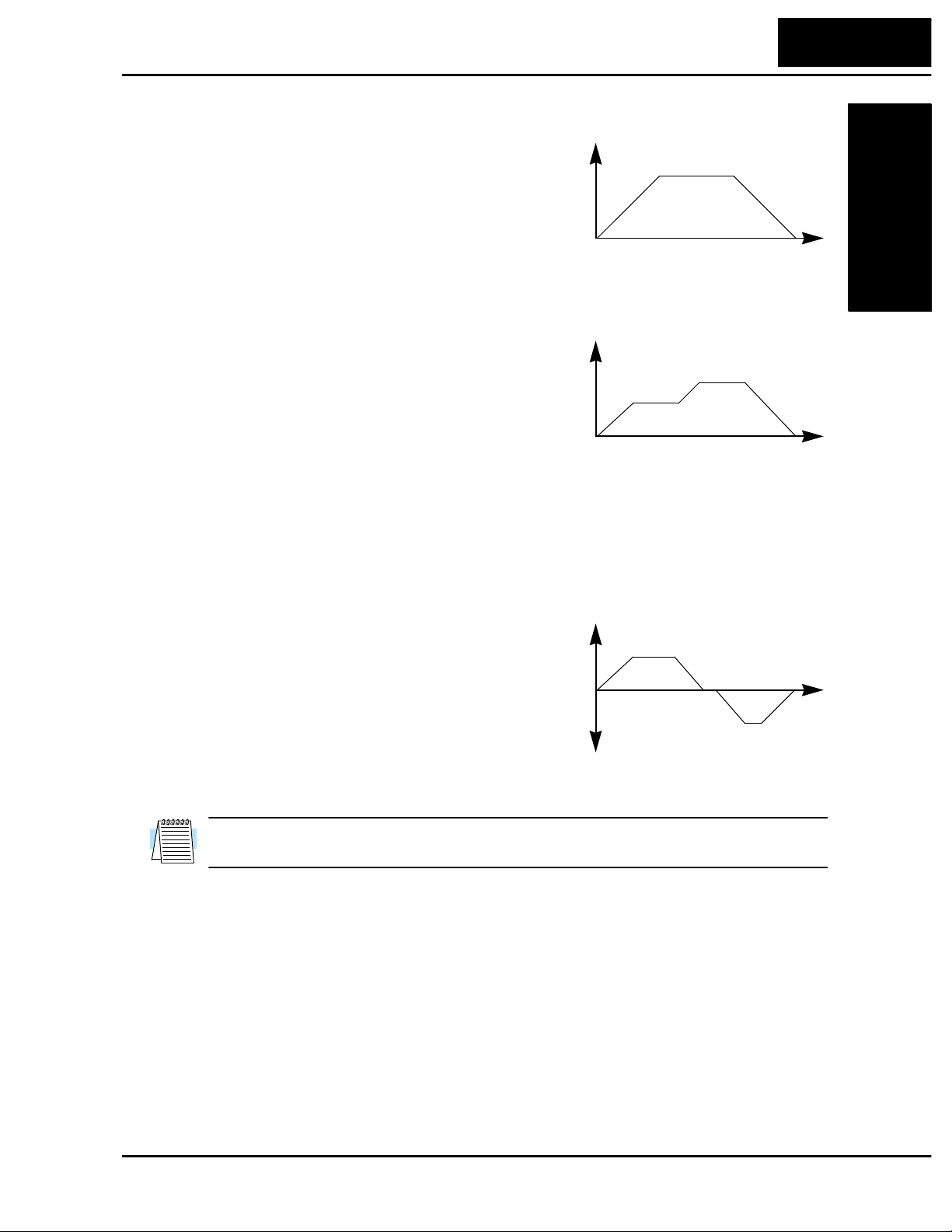
The L100 inverter is capable of sophisticated
speed control. A graphical representation of
that capability will help you understand and
program the associated parameters. This
manual makes use of the velocity profile
graph used in industry (shown at right). In the
example, the acceleration is a ramp to a set
speed, and the deceleration is a decline to a
stop.
Speed
L100 Inverter
1–11
Getting Started
Fixed speed
DecelAccel
Time
Velocity Profile
The L100 inverter can store up to 16 preset
speeds. And, it can apply separate accelera tion
and deceleration transitions from any prese t to
any other preset speed. For example, a motor
with a small load could use high accel/decel
values, but a heavy load will generally use
slower speed changes. A multi-speed profile
(shown at right) uses two or more preset
speeds in one motion of the load. There is no limit to the number of speed changes for
one motion; that is up to the control input to the inverter. Also note that speed can be
infinitely variable across the speed range. You can use the potentiometer control on the
keypad for manual control. The drive also acc epts analog 0-10V signals and 4-20 mA
control signals as well.
The inverter can drive the motor in either
direction. Separate FWD and REV commands
select the direction of rotation. The motion
profile example shows a forward motion
followed by a reverse motion of shorter
duration. The speed presets and analog signals
control the magnitude of the speed, while the
FWD and REV commands determine the
direction before the motion starts.
Speed
Speed
Speed 2
Speed 1
Time
Multi-speed Profile
Forward move
Time
Reverse move
Bi-directional Profile
NOTE: The L100 can move loads in both directions. However, it is not designed for use
in servo-type applications that use a bipolar velocity signal which determines direction.
Page 29

1–12
Technologies Inc.
Toll Free: voice: 1-877-539-2542 fax: 1-800-539-2542 www.mgitech.com
Frequently Asked Questions
Getting S tarted
Frequently Asked Questions
Q. What is the main advantage in using an inverter to drive a motor, compared to
alternative solutions?
A. An inverter can vary the motor speed with v ery little loss of eff iciency, unlike
mechanical or hydraulic speed control solutions. The resulting energy
savings usually pays for the inverter in a relatively short time.
Q. The term “inverter” is a little confusing, since we also use “drive” and “amplifier”
to describe the electronic unit that controls a motor. What does “inverter” mean?
A. The terms inverter, drive, and amplifier are used somewha t interchange ably
in industry. But there are subtle differences. A drive can refer to the motor,
the control electronics, or both. This term is used particularly when the
motor and electronics are integrated in the same housing. The term variable
speed drive can include many types of de vices – anything that has a variable
speed output, which includes the Hitachi inv erter. Amplifier more commonly
refers to a linear amplifier for servo motor control, or a stepper motor driver
IC. Finally, we use inverter to describe the Hitachi motor controller because
of the way the switching electronics alternately inverts or directly couples its
internal DC voltage bus to generate a variable AC output.
Q. Although the L100 inverter is a va riable speed drive, can I use it in a fixed-speed
application?
A. A fixed speed application usually is a result of cost-sensitivity or negligible
benefits if variable speed were used (consumer products are examples). In
those cases, the power source connects directly to the motor (no special driv e
needed). Howe ver, using a variable speed driv e can benefit many type of
industrial and commercial motor applications, by providing controlled acceleration and deceleration, high torque at low speeds, and energy savings over
alternative solutions.
Q. Can I use an inverter and AC induction motor in a positioning application?
A. That depends on the required precision, and the slowest speed the motor will
must turn and still deliver torque. If you set the torque boost, the L100 can
develop starting torque at 100% of its rating. However, DO NOT use an
inv erter if you need the motor to stop and hold the load position without the
aid of a mechanical brake (use a servo or stepper motion control system).
Q. Does the optional digital operator interface or the PC software (DOP Plus) provide
features beyond what is available from the keypad on the unit?
A. Yes. However, note first that the same set of parameters and functions are
equally accessible from either the unit’s keypad or from remote devices. The
DOP Plus PC software lets you save or load in verter configurations to or
from a disk file. And, the hand-held digital operator provides hard-wired
terminals, a safety requirement for some installations.
Page 30

L100 Inverter
Technologies Inc.
Toll Free: voice: 1-877-539-2542 fax: 1-800-539-2542 www.mgitech.com
1–13
Q. Why does the manual or other documentation use terminology such as “200V
class” instead of naming the actual voltage, such as “230 VAC?”
A. A speci fic inverter model is set at the factory to work across a voltage range
particular to the destination country for that model. The model specifications
are on the label on the side of the inverter. A European 200V class inverter
(“EU” marking) has different parameter settings than a USA 200V class
inverter (“US” marking). The initialization procedure (see page 6–8) can set
up the inverter for European or US commercial voltage ranges.
Q. Why is there not a 100V class version of the L100 inv erter , so it would work with a
USA 115VAC power source, for example?
A. A 100V version of the L100 may be available in the future. However, most
industrial, commercial, or heavy appliance applications use 230VAC in the
USA. Also, a built-in advantage is that using the higher voltage means less
current to deliver the same amount of power. This allows you to use smaller
diameter (and less expensive) wire for power and motor wiring.
Q. I live in a country where the domestic utility power is 115 VAC. Is there a way to
conveniently access a 230 VAC power source for a test bench to develop a motor
application?
Getting Started
A. A 1:2 step-up transformer is available from a number of sources (check your
local electrical supply house). The transformer will be designed to develop
230 VAC from 115 VAC, for example. Be s ure the power output rating (kW)
of the transformer is greater than 1.73 times the three-phase current of the
motor you intend to power . We recommend doing this for motors 1/2 horsepower or smaller , with small loads. F or 400 V class in v erters, we recommend
only using a utility power source of the correct voltage.
Q. Some models of Hitachi inverters will accept either single phase or three-phase
power input. How do I know which input power type to use?
A. If three-phase power is conveniently available for your application, we
recommend using that (the in v erter can develop its three-phase output power
most eff iciently from three-phase input power). In the absence of three-phase
power, you can use a single-phase power source with slightly less efficiency
but the power output rating is the same for N models (single or three-phase).
Q. If I decide to use single-phase input power for the inverter, can I also use a single-
phase motor?
A. No. All Hitachi inverters dev elop a v ariable three-phase output, requiring the
use of a three-phase AC induction motor.
Q. Why doesn’t the motor have a neutral connection as a return to the inverter?
A. T h e motor theoretically represents a “balanced Y” load if all three stator
windings have the same impedance. The Y connection allows each of the
three wires to alternately serve as input or return on alternate half-cycles.
Q. Does the motor need a chassis ground connection?
A. Yes, for several reasons. This is for protection in the event of a short in the
motor that puts a live voltage on its housing. Motors and other components
Page 31

1–14
Technologies Inc.
Toll Free: voice: 1-877-539-2542 fax: 1-800-539-2542 www.mgitech.com
Technologies Inc.
Toll Free: voice: 1-877-539-2542 fax: 1-800-539-2542 www.mgitech.com
Getting S tarted
Frequently Asked Questions
exhibit leakage currents that increase with aging. And, a grounded chassis
generally emits less electrical noise than an ungrounded one.
Q. What type of motor is compatible with the Hitachi inverters?
A. Motor type – it must be a three phase AC induction motor. Use an inverter-
grade motor that has 800V insulation for 200V class inverters, or 1600V
insulation for 400V class.
Motor size – In practice, it’s better to f ind the right size motor for your
application; then look for the inverter to match the motor.
Q. How many poles should the motor have?
A. Using a four-pole motor will work for most applications. The greater the
number of poles, the slower the top motor speed will be, but it will have
higher torque at the slowest speed.
Q. Will I be able to add dynamic (resistive) braking to my Hitachi L100 drive after the
initial installation?
A. Yes. You can connect a dynamic braking unit to the L100 inverter. The
resistor in the braking unit must be sized to meet the braking requirements.
Q. How will I know if my application will require resistive braking?
A. For new applications, it may be difficult to tell before you actually test a
motor/drive solution. In general, some applica tions can rely on system losses
such as friction to serve as the decelerating force, or otherwise can tolerate a
long deceleration time. These applications will not need dynamic braking.
However, applications with a combination of a high-inertia load and a
required short decel time will need dynamic braking. This is a physics
question that may be answered either empirically or through extensi v e calcu lations.
Q. Several options related to electrical noise suppression are available for the Hitachi
inv erters. How can I know if my application will require any of these options?
A. The purpose of these noise filters is to reduce the inverter electrical noise so
the operation of nearby electrical devices is not affected. Some applications
are governed by particular regulatory agencies, and noise suppression is
mandatory. In those cases, the inverter must have the corresponding noise
filter installed. Other applications may not need noise suppression, unless
you notice electrical interference with the operation of other devices.
Q. The L100 features a PID loop feature. PID loops are usually associated with
chemical processes, heating, or process industries in general. How could the PID
loop feature be useful in my application?
A. You will need to determine which main variable in your application the
motor affects. That is the process variable (PV) for the motor. Over time, a
faster motor speed will cause a faster change in the PV than a slo w motor
speed will. By using the PID loop feature, the inverter commands the motor
to run at the optimal speed required to maintain the PV at the desired value
for current conditions. Using the PID loop feature will require an additional
sensor and other wiring, and is considered an advanced application.
Page 32

Inverter Mounting
Technologies Inc.
Toll Free: voice: 1-877-539-2542 fax: 1-800-539-2542 www.mgitech.com
2
and Installation
In This Chapter.... page
— Orientation to Inverter Features....................... 2
— Basic System Description ................................5
— Step-by-Step Basic Installation ........................6
— Powerup Test ................................................. 17
— Using the Front Panel Keypad.......................19
Page 33

2–2
Technologies Inc.
Toll Free: voice: 1-877-539-2542 fax: 1-800-539-2542 www.mgitech.com
Orientation to Inverter Features
Orientation to Inverter Features
Unpacking and Inspection
Please take a few m oments to unpack your new L100 inverter and perform these steps:
1. Look for any damage that may have occurred during shipping.
2. Verify the contents of the box include:
a. One L100 inverter
b. One Instruction Manual with self-adhesive label for the inv erter
c. One L100 Quick-reference Guide
d. One packet of desiccant — discard (not for human consumption)
3. Inspect the specifications label on the side of the inverter. Make sure it matches the
product part number you ordered.
Main Physical Features
and Installation
Inverter Mounting
The L100 Series inverters vary in size according to the current output rating and motor
size for each model number. All feature the same basic keypad and connector interface
for consistent ease of use. The inverter construction has a heat sink at the back of the
housing. The larger models include a fan(s) to enhance heat sink performance. The
mounting holes are pre-drilled in the heat sink for your convenience. Never touch the
heat sink during or just after operation; it can be ve ry hot.
The electronics housing and front panel are built onto the front of the heat sink. The front
panel has three levels of physical access designed for convenience and safety:
• First-level access – for basic use of inverter during powered operation (power is On)
• Second-lev el access – for editing parameters and wiring control signals (power is On)
• Third-level access – for wiring the inverter power supply or motor (power is OFF)
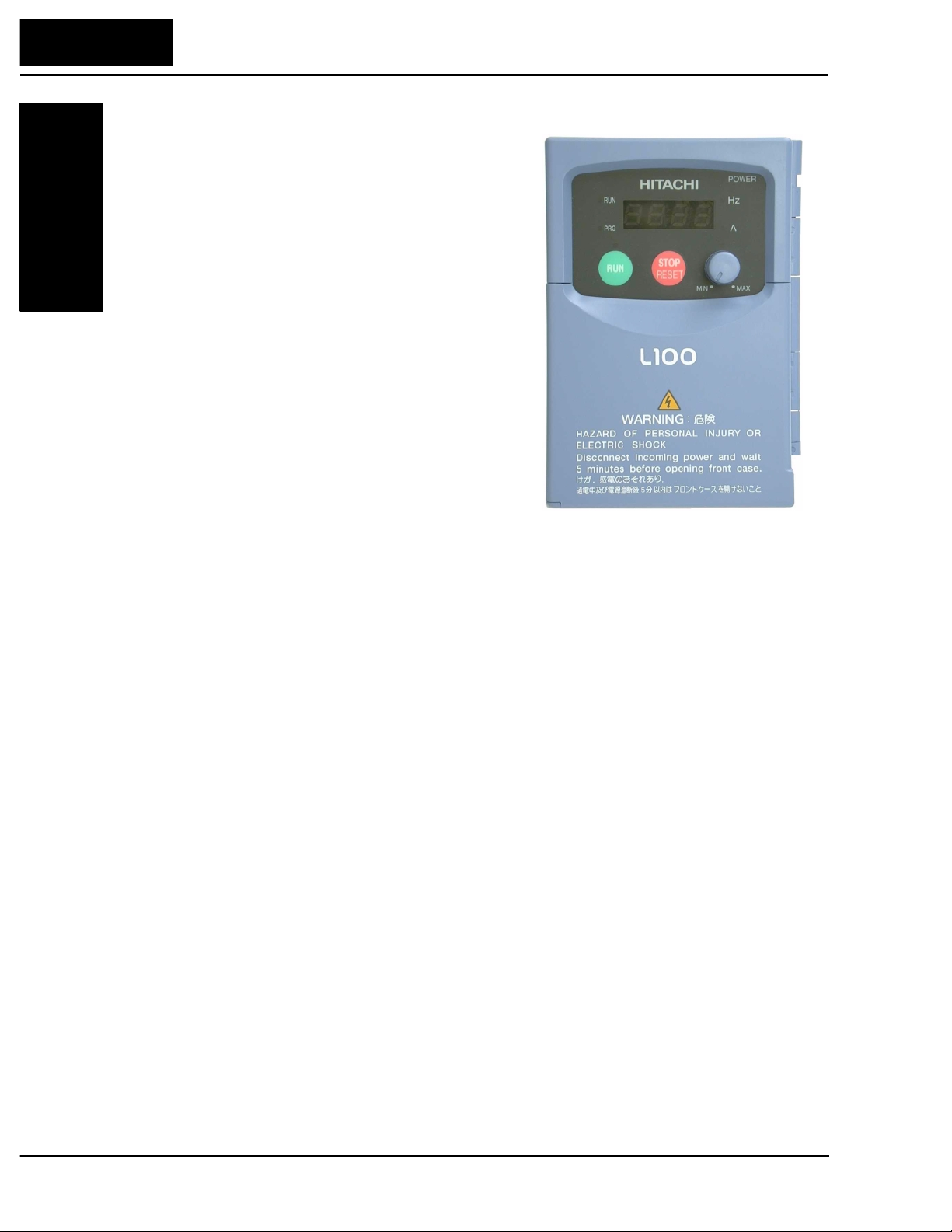
1. Firs t-level Access - View the unit just as it
came from the box as shown. The four-digit
display can show a varie ty of performance
parameters. LEDs indicate whether the
display units are Hertz or Amperes. Other
LEDs indicate Power (external), and Run/
Stop Mode and Program/Monitor Mode
status. Membrane keys Run and Stop/Reset,
and a Min/Max frequency control knob
control motor operation. These controls and
indicators are usually the only ones needed
after the inverter installation is complete.
You can also access the modular jack for
connecting a programming or monitoring
device such as a PC (see Chapter 3). And,
you can access the two chassis GND scre ws
on the metal tab at the bottom of the inverter.
Page 34

L100 Inverter
Technologies Inc.
Toll Free: voice: 1-877-539-2542 fax: 1-800-539-2542 www.mgitech.com
2. Second-level access - Locate the lift tab at the right lower corner of the front panel
near the safety warning message. Lift the corner to swing the half-door around to the
left. This exposes four more control buttons and some connectors.
The FUNC., , , and STR keys allow an operator to access and change the
2
1
inverter’s functions and parameter values. The 7 and 8-position connectors provide
the interface for logic-level control signals. These signals are generally low-voltage in
nature and are appropriate for second-level access.
Controls for mode
and parameter
changes
2–3
and Installation
Inverter Mounting
Lift tab for
opening door
Control signal
connectors
Locate the label sheet that came with the manual. This is a good moment to apply the
self-sticking labels as shown below. Adhere the larger label for monitor codes and
basic functions to the rear of the half-door panel. Then adhere the remaining trip code
label to the area beside the connectors. Be careful not to cover the screw access on
models like the one shown.
Page 35

2–4
Technologies Inc.
Toll Free: voice: 1-877-539-2542 fax: 1-800-539-2542 www.mgitech.com
and Installation
Inverter Mounting
Orientation to Inverter Features
3. Third-level access - First, ensure no power
source of any kind is connected to the
inv erter. If power has been connected, wait
five minutes after powerdown and verify
the Power LED is off to proceed. Then
locate the recessed retention screw on the
left side main front panel (it is along the
left hinge area on some models, or behind
the first access door on others). Use a small
screwdriv e r (Regular or Phillips) to loosen
the screw . Swing the door around to the left
to reveal the internal components of the
drive. The two-level tiered 12-position
terminal block accepts wires for the power
input and wires to the motor.
Notice the housing partition that lifts out to
allow full access to the te rminals for wiring as
shown. Never operate the inverter drive with
the partition removed or the full access door
opened.
The alarm circuit connections are accessible
on the 3-position connector near the modular
connector on the rear of the main panel door.
The nearby relay provides both normallyopen and normally-closed logic for interface
to an external alarm. The alarm circuit may
carry hazardous live voltages even when the
main power to the inverter is off. So, never
directly touch any component on the circuit board in the panel door. A notch in the
removable partition serves as the exit path for alarm circuit wiring.
Housing partition
Retention screw
Alarm
connector
The following sections will describe the
system design and guide you through a
step-by-step installation process. After the
section on wiring, this chapter will show
how to use the front panel keys to acces s
functions and edit parameters.
Power and motor
connector terminals
Page 36

Basic System Description
Technologies Inc.
Toll Free: voice: 1-877-539-2542 fax: 1-800-539-2542 www.mgitech.com
A motor control system will obviously include a motor and inverter, as well as fuses for
safety. If you are connecting a motor to the inverter on a test bench just to get started,
that’s all you may need for now. But a system can also have a variety of additional
components. Some can be for noise suppression, while others may enhance the inv erter’s
braking performance. The figure and table below show a system with all the optional
components you may need in your finished application.
From power supply
L100 Inverter
2–5
L1L3L2
Inverter
T1
Motor
+1
+
–
GND
T3T2
Cut-off
switch
Name Function
Fuse Current overload protection for power
supply and wiring.
Input-side
AC Reactor
Radio noise filter Electrical noise interference may occur on
EMI filter (for
CE applications)
Radio noise filter
(use in non-CE
applications)
DC link choke Suppresses harmonics generated by the
Dynamic
braking unit &
resistor
Radio noise filter Electrical noise interference may occur on
AC reactor This reactor reduces the vibrations in the
LCR filter Sine wave shaping filter for output side.
This is useful in suppressing harmonics
induced on the power supply lines, or when
the main power voltage imbalance exceeds
3% (and power source capacity is more
than 500 kVA), or to smooth out line fluctuations. It also improves the power factor.
nearby equipment such as a radio receiver.
This magnetic choke filter helps reduce
radiated noise (can also be used on output).
Reduces the conducted noise on the power
supply wiring generated by the main power
supply to protect the inverter. Connect to
the inverter primary (input side).
This capacitiv e fil ter reduces radiated nois e
from the main power wires in the inverter
input side.
inverter. However, it will not protect the
input diodes.
This is useful for increasing the inverter’s
control torque for high duty-cycle (on-off)
applications, and improving the decelerating capability .
nearby equipment such as a radio receiver.
This magnetic choke filter helps reduce
radiated noise (can also be used on input).
motor caused by the inverter’s switching
waveforms, by smoothing the waveforms to
approximate commercial power quality. It
is also useful when wiring from the inverter
to the motor is more than 10m in length, to
reduce harmonics.
and Installation
Inverter Mounting
Thermal switch
Note that some components are required for regulatory
agency compliance (see Chapter 5).
Page 37

2–6
Technologies Inc.
Toll Free: voice: 1-877-539-2542 fax: 1-800-539-2542 www.mgitech.com
and Installation
Inverter Mounting
Step-by-Step Basic Installation
Step-by-Step Basic Installation
This section will guide you through the following basic steps of installation:
1. Study the warnings associated with mounting the inverter.
2. Select a suitable mounting location.
3. Place covers over the inverter’s ventilation openings to prevent debris from entering.
4. Check the inverter mounting dimensions for footprint and mounting hole locations.
5. Study the caution and warning messages associated with wiring the inverter.
6. Connect wiring for the inverter power input.
7. Connect wiring to the motor.
8. Remove any covers applied in Step 3 from the inverter’s ventilation openings.
9. Perform a powerup test.
10. Make observations and check your installation.
Choosing a Mounting Location
Step 1: Study the following caution messages associated with mounting the inverter.
1
This is the time when mistakes are most likely to occur that will result in expensive
rework, equipment damage, or personal injury.
CAUTION: Be sure to install the unit on flame-resistant material such as a steel plate.
Otherwise, there is the danger of fire.
CAUTION: Be sure not to place any flammable materials near the inverter. Otherwise,
there is the danger of fire.
CAUTION: Be sure not to let the foreign matter enter vent openings in the inverter
housing, such as wire clippings, spatter from welding, metal shavings, dust, etc. Otherwise, there is the danger of fire.
CAUTION: Be sure to install the inverter in a place which can bear the weight according to the specifications in the text (Chapter 1, Specifications Tables). Otherwise, it may
fall and cause injury to personnel.
CAUTION: Be sure to install the unit on a perpendicular wall which is not subject to
vibration. Otherwise, it may fall and cause injury to personnel.
CAUTION: Be sure not to install or operate an inverter which is damaged or has
missing parts. Otherwise, it may cause injury to personnel.
CAUTION: Be sure to install the inverter in a well-ventilated room which does not ha v e
direct exposure to sunlight, a tendency for high temperature, high humidity or dew
condensation, high leve ls of dust, corrosive gas, explosive gas, inflammable gas,
grinding-fluid mist, salt damage, etc. Otherwise, there is the danger of fire.
Page 38

L100 Inverter
Technologies Inc.
Toll Free: voice: 1-877-539-2542 fax: 1-800-539-2542 www.mgitech.com
Step 2: To summarize the caution messages — you will need to find a solid, non-
2
flammable, vertical surface that is a relatively clean and dry environment. In order to
ensure enough room for air circulation around the inverter to aid in cooling, maintain the
specified clearance around the inverter specified in the diagram.
2–7
Clear area
8 cm (3.15”)
minimum
Step 3: Before proceeding to the wiring section, it’s a good time to temporarily cover the
3
inverter’s ventilation openings. Paper and masking tape is all that is needed to do this. It
will prevent harmful debris such as wire clippings and metal shavings from entering the
inverter during installation. The inverter housing comes from the factory with a snap-in
cover on the top of its housing. Ensure it is in place at this time (also to be removed later ,
unless the installation must have a NEMA rating).
10 cm (3.94”)
minimum
L100
10 cm (3.94”)
minimum
12 cm (4.72”)
minimum
Air flow
and Installation
Inverter Mounting
T op cover
installed
Please observe this checklist while mounting the inverter:
1. The ambient temperature must be in the range of -10 to 40°C. If the range will be up
to 50°C, you will need to set the carrier frequency to 2.1 kHz or less and derate the
output current to 80% or less. Chapter 3 covers ho w to change pa rameters such as the
carrier frequency. Remember to remove the top cover (unless the installation is to
have a NEMA rating)!
2. Keep any other heat-producing equipment as far away from the in verter as possible.
3. When installing the inverter in an enclosure, maintain the clearance around the
inv erter and verify that its ambient temperature is within specification when the
enclosure door is closed.
4. Do not open the main front panel door at any time during operation.
Ventilation holes
(both sides)
Page 39

2–8
Technologies Inc.
Toll Free: voice: 1-877-539-2542 fax: 1-800-539-2542 www.mgitech.com
Step-by-Step Basic Installation
In verter Dimensions for Mounting
Step 4: Locate the applicable drawing on the following pages for your inverter.
4
Dimensions are given in millimeters (inches) format.
External Dimensions
MODEL H mm (in.)
L100
and Installation
Inverter Mounting
-002NFE
-002NFU
-004NFE
-004NFU
107 (4.21)
107 (4.21)
107 (4.21)
107 (4.21)
110(4.33)
67(2.64)
5(0.20)
80(3.15)
4(0.16)
120(4.72)
10(0.39)
7(0.28)
2.5(0.10)
H= (see H chart)
NOTE: Some inverter housings require two mounting screws, while others require four.
Be sure to use lock washers or other means to ensure screws do not loosen due to
vibration.
Page 40

Dimensional drawings continued...
FAN
Technologies Inc.
Toll Free: voice: 1-877-539-2542 fax: 1-800-539-2542 www.mgitech.com
External Dimensions
MODEL
L100
-004HFE
-004HFU
-005NFE
-007NFE
-007NFU
118(4.65)
L100 Inverter
2–9
98(3.86)
130(5.12)
MODEL
L100 -007HFE(No fan)
-007HFU(No fan)
-015HFE
-015HFU
10(0.39)
5(0.20)
110(4.33)
98(3.86)
5(0.20)
4(0.16)
129(5.08)
2.5(0.10)
Ground Terminal
7(0.28)
Air
and Installation
Inverter Mounting
118(4.65)
5(0.20)
110(4.33)
Ground Terminal
130(5.12)
5(0.20)
4(0.16)
156(6.14)
6(0.24)
Air
7(0.28)
Page 41

2–10
Technologies Inc.
Toll Free: voice: 1-877-539-2542 fax: 1-800-539-2542 www.mgitech.com
Step-by-Step Basic Installation
Dimensional drawings continued...
L100
-011NFE
-015NFE
-015NFU
140(5.51)
128(5.04)
168(6.61)
180(7.09)
5(0.20)
5(0.20)
10(0.39)
and Installation
Inverter Mounting
L100
-022NFE
-022NFU
140(5.51)
128(5.04)
7(0.28)
153(6.02)
3.5(0.14)
Ground Terminal
Air
-022HFE
-022HFU
-030HFE
-037LFU
-040HFE
-040HFU
168(6.61)
180(7.08)
5(0.20)
Ground Terminal
FAN
5(0.20)
Air
7(0.28)
164(6.46)
6(0.24)
Page 42

Dimensional drawings continued...
Technologies Inc.
Toll Free: voice: 1-877-539-2542 fax: 1-800-539-2542 www.mgitech.com
L100 -055LFU
-075LFU
-055HFU
-075HFU
-055HFE
-075HFE
182(7.17)
160(6.30)
1
236(9.29)
257(10.12)
L100 Inverter
Air
2–11
and Installation
Inverter Mounting
7(0.28)7(0.28)
Ground Terminal
Air
7(0.28)
170(6.69)
6(0.24)
NOTE: Model L100-075LFU has (2) fans. All other models in this housing have (1) fan.
Page 43

2–12
Technologies Inc.
Toll Free: voice: 1-877-539-2542 fax: 1-800-539-2542 www.mgitech.com
and Installation
Inverter Mounting
Step-by-Step Basic Installation
Preparation for Wiring
Step 5: It is very important to perform the wiring steps carefully and correctly . Before
5
proceeding, please study the caution and warning messages below.
WARNING: “Use 60/75°C Cu wire only” or equivalent.
WARNING: “Open Type Equipment.”
WARNING: “A Class 2 circuit wired with Class 1 wire” or equivalent.
WARNING: “Suitable for us e on a circuit capable of deli vering not more than 5,000 rms
symmetrical amperes, 240 V maximum.” For models with suffix N or L.
WARNING: “Suitable for us e on a circuit capable of deli vering not more than 5,000 rms
symmetrical amperes, 480 V maximum.” For models with suffix H.
HIGH VOLTAGE: Be sure to ground the unit. Otherwise, there is a danger of electric
shock and/or fire.
HIGH VOLTAGE: Wiring work shall be carried out only by qualif ied personnel. Otherwise, there is a danger of electric shock and/or fire.
HIGH VOLTAGE: Implement wiring after checking that the power supply is off. You
may incur electric shock and/or fire.
HIGH VOLT A GE: Do not connect wiring to an inverter or operate an inv erter that is not
mounted according the instructions given in this manual. Otherwise, there is a danger of
electric shock and/or injury to personnel.
Page 44

Determination of Wire and Fuse Sizes
Technologies Inc.
Toll Free: voice: 1-877-539-2542 fax: 1-800-539-2542 www.mgitech.com
The maximum motor currents in your application determines the recommended wire
size. The following table giv es the wire size in AWG. The “Power Lines” column applies
to the inverter input power, output wires to the motor, the earth ground connection, and
any other component shown in the system wiring diagram on page 2–5. The “Signal
Lines” column applies to any wire connecting to the two green 7 and 8-position connectors just inside the front panel half-door.
L100 Inverter
2–13
Motor Output
(kW/HP)
Wiring
Inverter Model
kW HP Power Lines Signal Lines
0.2 1/4 L100-002NFE/NFU
AWG16 / 1.3 mm
2
0.55 3/4 L100-005NFE
.75 1 L100-007NFE/NFU
AWG14 / 2.1 mm
2
1.1 1 1/2 L100-011NFE
1.5 2 L100-015NFE/NFU
2.2 3 L100-022NFE/NFU
3.7 5 L100-037LFU
5.5 7 1/2 L100-055LFU
7.5 10 L100-075LFU
AWG12 / 3.3 mm
AWG10 / 5.3 mm
AWG12 / 3.3 mm
AWG10 / 5.3 mm
AWG8 / 8.4 mm
2
2
2
18 to 28 AWG /
2
0.14 to 0.75 mm
shielded wire
2
(*)
0.4 1/2 L100-004HFE/HFU
Applicable
equipment
Fuse (class J)
rated 600V
10A0.4 1/2 L100-004NFE/NFU
15A
20 A (single ph.)
15A (three ph.)
30A (single ph.)
20A (three ph.)
30A
2
40A
50A
3A
and Installation
Inverter Mounting
0.75 1 L100-007HFE/HFU 6A
AWG16 / 1.3 mm
2
1.5 2 L100-015HFE/HFU
10A
2.2 3 L100-022HFE/HFU
3.0 4 L100-030HFE
4.0 5 L100-040HFE/HFU
5.5 7 1/2 L100-055HFE/HFU
AWG14 / 2.1 mm
AWG12 / 3.3 mm
2
2
15A
20A
7.5 10 L100-075HFE/HFU 25A
Note 1: Field wiring must be made by a UL- listed and CSA-certified closed-loop
terminal connector sized for the wire gauge involv ed. Connector must be fixed by using
the crimping tool specified by the connector manufacturer.
Note 2: Be sure to consider the capacity of the circuit breaker to be used.
Note 3: Be sure to use larger wires for the power lines if the distance exceeds 20 meters.
2
(*) Use 18 AWG / 0.75 mm
wire for the alarm signal wire (AL0, AL1, AL2 terminals).
Page 45

2–14
Technologies Inc.
Toll Free: voice: 1-877-539-2542 fax: 1-800-539-2542 www.mgitech.com
and Installation
Inverter Mounting
Step-by-Step Basic Installation
Wiring the Inverter Input to a Power Supply
Step 6: In this step, you will connect wiring to
6
the input of the inverter. First, you must determine whether the inverter model you have
requires three-phase power only, or if it can
accept either single-phase or three-phase power.
All models have the same power connector
terminals labeled L1, L2, and L3/N. So, you
must refer to the specifications label (on the
side of the inverter) for the acceptable power
source types! For inverters which can accept
single-phase power and are connected that
way, terminal L2 will remain unconnected.
The wiring example to the right shows an L100
inv erter wired for 3-phase input. Note the use of
spade lug connectors for a secure connection.
NOTE: An inverter powered by a portable power generator may recei ve a distorted
power wa v eform, o v erhea ting the generator. In general, the generator capacity should be
five times that of the inverter (kVA) in a PWM (pulse-width modulated) control system,
or six times greater in a PAM (pulse-amplitude modulated) control system.
CAUTION: Be sure that the input voltage matches the inverter specifications:
• Single/Three phase 200 to 240 V 50/60 Hz (up to 2.2kW)
• Three phase 200 to 230V 50/60Hz (above 2.2kW)
• Three phase 380 to 460 V 50/60Hz
CAUTION: Be sure not to input a single phase to a three-phase-only type inverter.
Otherwise, there is the danger of fire.
CAUTION: Be sure not to connect an AC power supply to the output terminals. Otherwise, there is the danger of injury and/or fire.
Power Input Power Output
(L) (N)
L1 L2 L3
T1 T2 T3
UVW
NOTE:
L, N:
L1, L2, L3:
Single-phase 200 to 240V 50/60 Hz
Three-phase 200 to 230V 50/60 Hz
Three-phase 380 to 460V 50/60 Hz
Page 46

L100 Inverter
Technologies Inc.
Toll Free: voice: 1-877-539-2542 fax: 1-800-539-2542 www.mgitech.com
2–15
CAUTION: Fasten the screws with the specified fastening torque (see the following
table). Check for any loosening of screws. Otherwise, there is the danger of fire.
CAUTION: Remarks for using earth leakage circuit breakers in the mains supply:
Frequency inverters with CE-filters (RFI-filter) and shielded (screened) motor cables
have a higher leakage current to ward Earth GND. Especially at the moment of switching
on this can cause inadvertent tripping of earth leakage circuit breakers. Because of the
rectifier on the input side of the inverter there is the possibility to stall the switch-off
function through small amounts of DC current. Please observe the following:
• Use only short time-invariant and pulse current-sensitive earth leakage circuit
breakers with higher trigger current.
• Other components should be secured with separate earth leakage circuit breakers.
• Earth leakage circuit breakers in the power input wiring of an in verter are not an
absolute protection against electric shock by direct touching.
CAUTION: Be sure to install a fuse in the wire for each phase of the main po wer supply
to the inverter. Otherwise, there is the danger of fire.
and Installation
Inverter Mounting
CAUTION: For motor leads, earth leakage breakers and electromagnetic contactors, be
sure to size these components properly (each must have the capacity for rated current
and voltage). Otherwise, there is the danger of fire.
Terminal Dimensions and Tightening Torque
The terminal screw dimensions for all L100 inv erters are listed in table below. This
information is useful in sizing spade lug or ring lug connectors for wire terminations.
Number of
Connector
Power Terminals 12 M3.5 7.1 M4 9
Control Signal 15 M2 – M2 –
Alarm Signal 3 M3 – M3 –
Ground Terminals 2 M4 – M4 –
Screw
Terminals
Models 002NF, 004NF, 005NF
Screw
Diameter
Width (mm)
When connecting wiring, use the tightening torque listed in the following table to safely
attach wiring to the connectors.
Models 007NF–022NF,
037LF, 004HF–075HF
Screw
Diameter
Width(mm)
Screw Tightening Torque Screw Tightening Torque
M2 0.2 N•m (max. 0.25 N•m) M3.5 0.8 N•m (max. 0.9 N•m)
M3 0.5 N•m (max. 0.6 N•m) M4 1.2 N•m (max. 1.3 N•m)
Page 47

2–16
Technologies Inc.
Toll Free: voice: 1-877-539-2542 fax: 1-800-539-2542 www.mgitech.com
and Installation
Inverter Mounting
Step-by-Step Basic Installation
Wiring the Motor to the Inverter Output
Step 7: The process of motor selection is beyond the scope of this manual. However, it
7
must be an AC induction motor with three phases. It should also come with a chassis
ground lug. If the motor does not have three power input leads, stop the installation and
verify the motor type. Other guidelines for wiring the motor include:
• Use an in verter-grade motor for maximum motor life (1600V insulation).
• For standard motors, use the AC reactor accessory if the wiring between the inverter
and motor exceeds 10 meters in length.
Simply connect the motor to the terminals
indicated on the inverter to the right. The
terminals are labeled U/T1, V/T2, and W/T3.
This is a good time to connect the chassis
ground lug on the drive as well. The motor
chassis ground must also connect to the same
point. Use a star ground (single-point)
arrangement, and neve r daisy-chain the
grounds (point-to-point).
Use the same wire gauge on the motor and
chassis ground wiring as you used on the
power input wiring in the previous step. After
completing the wiring:
• Replace the housing partition that covers
access to the power connections.
• Close the main door and secure the retention screw firmly.
Other Wiring - After the initial installation
To Power
Supply
To Motor To Chassis
Ground
and powerup test, you may need to wire the
remaining connectors — the control signal connector, and the alarm circuit connector.
This is covered in detail on page 4–22.
Step 8: After mounting and wiring the inverter,
8
it’s time to remov e any covers from the in verter
housing. This includes covers ov er the side
ventilation ports. Remove the square cov er panel
at the top of the housing, unless the application
must maintain a NEMA rating.
WARNING: Make sure the input po wer to the
inv erter is off. If the drive has been powered,
leave it off for five minutes before continuing.
The top housing cover is held in place by four locking tabs. To remove the cover,
squeeze two corners together and push a small screwdriver under one side as shown,
while pulling upward. Hold the screwdriver at the angle shown, and DO NO T push the
screwdriver or any object through ventilation openings and into the inverter .
Page 48

Powerup Test
Technologies Inc.
Toll Free: voice: 1-877-539-2542 fax: 1-800-539-2542 www.mgitech.com
Step 9: After wiring the inverter and motor, you’re ready to do a powerup test. The
9
procedure that follows is designed for the first-time use of the drive. Please verify the
following conditions before conducting the powerup test:
• You have followed all the steps in this chapter up to this step.
• The in verter is new, and is securely mounted to a non-flammable vertical surface
• The inverter is connected to a power source and motor .
• No additional wiring of inverter connectors or terminals has been done.
• The power supply is reliable, and the motor is a known working unit.
• The motor is securely mounted, and is not connected to any load.
Goals for the Powerup Test
If there are any exceptions to the above conditions at this step, please take a moment to
take any measures necessary to reach this basic starting point. The specific goals of this
powerup test are:
L100 Inverter
2–17
and Installation
Inverter Mounting
1. Verify that the wiring to the power supply and motor is correct.
2. Demonstrate that the inverter and motor are generally compatible.
3. Give a brief introduction to the use of the built-in operator keypad.
The powerup test gives you an important starting point to ensure a safe and successful
application of the Hitachi inverter. We highly recommend performing this test before
proceeding to the other chapters in this manual.
Pre-test and Operational Precautions
The following instructions apply to the powerup test, or to any time the inverter is
powered and operating. Please study the following instructions and messages before
proceeding with the powerup test.
1. The power supply must have fusing suitable for the load. Check the fuse size chart
presented in Step 5, if necessary.
2. Be sure you have access to a cut-off switch for the drive input power if necessary.
Howe ver, do not turn off power to the inverter during its operation unless it is an
emergency.
3. Turn the in v erter’s front panel potentiometer to the MIN position (fully counter-clock-
wise).
CAUTION: The heat sink fins will have a high temperature. Be careful not to touch
them. Otherwise, there is the danger of getting burned.
CAUTION: The operation of the inverter can be easily changed from low speed to high
speed. Be sure check the capability and limitations of the motor and machine befor e
operating the inverter. Otherwise, there is the danger of injury.
Page 49

2–18
Technologies Inc.
Toll Free: voice: 1-877-539-2542 fax: 1-800-539-2542 www.mgitech.com
Technologies Inc.
Toll Free: voice: 1-877-539-2542 fax: 1-800-539-2542 www.mgitech.com
Powerup Test
CAUTION: If you operate a motor at a frequency higher than the inverter standard
default setting (50Hz/60Hz), be sure to check the motor and mac hine specif ica tions with
the respective manu facturer. Only operate the motor at elevated frequencies after getting
their approval. Otherwise, there is the danger of equipment damage.
CAUTION: Check the following before and during the po werup test. Otherwise, there is
the danger of equipment damage.
• Is the shorting bar between the +1 and + terminals installed? DO NOT powe r or
operate the inverter if the jumper is removed.
• Is the direction of the motor correct?
• Did the inverter trip during acceleration or deceleration?
• Were the rpm and frequency meter readings as expected?
• Were there any abnormal motor vibrations or noise?
Powering the Inverter
and Installation
Inverter Mounting
If you have follo wed all the steps, cautions and w arnings up to this point, you’re ready to
apply power. After doing so, the following events should occur:
• The POWER LED will illuminate.
• The numeric (7-segment) LEDs will display a test pattern, then stop at 0.0.
• The Hz LED will be on.
If the motor starts running unexpectedly or any other problem occurs, press the STOP
button. Only if necessary should you remove power to the inverter as a remedy .
NOTE: If the inverter has been previously powered and programmed, the LEDs (other
than the PO WE R L E D) may illuminate differently than as indicated above. If necessary ,
you can initialize all parameters to the factory default settings. See the initialization
instructions on page 6–8.
Page 50

Using the Front Panel Keypad
Technologies Inc.
Toll Free: voice: 1-877-539-2542 fax: 1-800-539-2542 www.mgitech.com
Front Panel Introduction
Please take a moment to familiarize yourself with the keypad layout shown in the f igure
below. These are the visible controls and indicators when the front panel door is closed.
Parameter Display
L100 Inverter
2–19
Run/Stop LED
Program/Monitor LED
Run Enable LED
Run Button
The display is used in programming the inverter’s parameters, as well as monitoring
specific parameter values during operation. Many functions are applicable only during
the initial installation, while others are more useful for maintenance or monitoring.
Parameter Editing Controls
Now, open the front panel (half-door) for second-level access to reveal additional
operator keys for parameter editing as shown belo w. In normal operation after installation, parameter editing is unnecessary, so these controls are hidden from view.
The front panel controls and indicators are described as follows:
• Run/Stop LED - On when the inverter output is running the motor (Run Mode), and
Off when the inverter output is Off (Stop Mode).
• Program/Monitor LED - This LED is On when the inverter is ready for parameter
editing (Program Mode). It is Off when the parameter display is monitoring data
(Monitor Mode).
MIN
POWER
Hz
A
MAX
RUN
PRG
RUN
HITACHI
050
STOP
STOP
STOPSTOP
RESET
Stop/Reset Button
Power LED
Display Units
Hertz / Amperes LEDs
Potentiometer Enable LED
Potentiometer
and Installation
Inverter Mounting
• Run Enable LED - is On when the inverter is ready to respond to the Run command,
Off when the Run command is disabled.
• Run Key - Press this key to run the motor (the Run Enable LED must be On first).
• Stop/Reset Key - Press this key to stop the motor when it is running (uses the
programmed deceleration rate). This key will also reset an alarm which has tripped.
• Potentiometer - allows an operator to enter data for selecting a scalar value from a
range, associated with the inverter output frequency.
• Potentiometer Enable LED - On when the potentiometer is enabled for value entry.
• Parameter Display - a 4-digit, 7-segment display for parameters and function codes.
• Display Units, Hertz/Amperes - One of these LEDs will be On to indicate the units
associated with the parameter display.
• Power LED - This LED is On when the power input to the inverter is on.
Page 51

2–20
Technologies Inc.
Toll Free: voice: 1-877-539-2542 fax: 1-800-539-2542 www.mgitech.com
and Installation
Inverter Mounting
Using the Front Panel Keypad
• Function Key - This key is used to naviga te
through the lists of parameters and functions
for setting and monitoring parameter values.
• Up/Down ( , ) Keys - Use these keys
2
1
alternately to move up or down the lists of
parameter and functions shown in the display,
and increment/decrement values.
• Store ( ) Key - When the unit is in
STR
Program Mode and the operator has edited a
parameter value, press the Store key to write
the new value to the EEPROM.
Keys, Modes, and Parameters
Purpose of the keypad is to provide a way to change modes and parameters. The term
function applies to both monitoring modes and parameters. These are all accessible
through function codes, which are primarily 3-character codes. The v arious functions a re
separated into related groups identifiable by the left-most character, as the table shows.
Function
Group
Type (Category) of Function Mode to Access
Function
key
HITACHI
RUN
PRG
RUN
FUNC.
1
Up/Down
keys
PGM LED
Indicator
050
STOP
STOP
STOPSTOP
RESET
MIN MAX
2
POWER
Hz
A
STR
Store
key
“D”
“F”
“A”
“B”
“C”
“E”
Monitoring functions
Basic profile pa rameters
Standard functions
Fine tuning functions
Intelligent terminal functions
Error codes
Monitor
Program
Program
Program
Program
——
For example, function “A04” is the base frequency setting for the motor , typically 50 Hz
or 60 Hz. To edit the parameter, the inverter must be in Program Mode (PGM LED will
be On). You use the front panel keys to first select the function code “A 04.” After
displaying the value for “A 04,” use the Up/Down ( or ) keys to edit the value.
1
2
NOTE: The inverter 7-segment display shows lower case “b” and “d”, which means the
same as the upper case letters “B” and “D” used in this manual (for uniformity “A to F”).
The inverter automatically switches into Monitor
MONITOR PROGRAM
Mode when you access “D” group functions. It
switches into Program Mode when you access any
other group, because they all have editable parameters. Error codes use the “E” group, and appear
“D” Group
“A” Group
“B” Group
“C” Group
“F” Group
automatically when a fault event occurs. Refer to
page 6–5 for error code details.
Page 52

Keypad Navigational Map
2
1
FUNC. FUNC.
Technologies Inc.
Toll Free: voice: 1-877-539-2542 fax: 1-800-539-2542 www.mgitech.com
The L100 Series inverter drives have many progr ammable functions and parameters.
Chapter 3 will cover these in detail, but we need to ac cess just a fe w items to perform the
powerup test. The menu structure makes use of function codes and parameter codes to
allow programming and monitoring with only a 4-digit display and a few buttons and
LEDs. So, it is important to become familiar with the basic navigational map of parameters and functions in the diagram below. You may later use this map as a reference.
L100 Inverter
2–21
Monitor Mode
Display
Data
0000
PRG LED = OFF
1
09D
1
FUNC.
01D
1
--C
1
--B
1
--A
1
Program Mode
PRG LED = ON
Select ParameterSelect Function
Edit Parameter
Increment/
decrement
1
2
91C
FUNC.
1
2
FUNC.
1
2
2
FUNC.
FUNC.
1
1
2
01C
2
92B
01B
FUNC.
2
FUNC.
2
98A
2
1
2
value
2
1
Edit
3241
STR
Write
data to
EEPROM
FUNC.
and Installation
Inverter Mounting
04F
1
2
FUNC.
01A
2
01F
2
The navigational map shows the relationship of all resources of
the inve rter in one vie w. In general, use the key to move left
and right, and the (arrow) keys to move up and down.
2
1
Other tables in this chapter will show how to set up a particular
parameter, for exa mple. However , the map abo ve gives the “big
picture” for functions in general.
FUNC.
Return to
parameter
list
Page 53

2–22
Technologies Inc.
Toll Free: voice: 1-877-539-2542 fax: 1-800-539-2542 www.mgitech.com
and Installation
Inverter Mounting
Using the Front Panel Keypad
Selecting Functions and Editing Parameters
In order to run the motor for the powerup test, this section will show how to:
• select the in verter’s maximum output frequency to the motor
• select the keypad potentiometer as the source of motor speed command
• select the keypad as the source of the RUN command
• enable the RUN command
The following series of programming tables are designed for successive use. Each table
uses the previous table’s final state as the starting point. Therefore, start with the f irst and
continue programming until the last one. If you get lost or concerned that some of the
other parameters settings may be incorrect, refer to the section on restoring factory
default settings on page 6–8.
CAUTION: If you operate a motor at a frequency higher than the inverter standard
default setting (50Hz/60Hz), be sure to check the motor and mac hine specif ica tions with
the respective manu facturer. Only operate the motor at elevated frequencies after getting
their approval. Otherwise, there is the danger of equipment damage.
Setting the Motor Base Frequen cy -The motor is designed to operate at a specific AC
frequency. Most commercial motors are designed for 50/60 Hz operation. First, check
the motor specifications. Then follow the steps in the table below to verify the setting or
correct for your motor. DO NOT set it for greater than 50/60 Hz unless the motor
manufacturer specifically approv es operation at the higher frequency.
Action Display Func./Parameter
Press the
Press the
Press the
Press the
Press the
FUNC.
key.
1
FUNC.
1
FUNC.
2
or keys until ->
key.
key twice.
key.
01D
--A
01A
03A
60
or
Monitor functions
“A” group selected
First “A” parameter
Base frequency setting
Default value for base frequency.
US = 60 Hz, Europe = 50 Hz.
50
Press the
Press the
1
STR
2
or key as needed.
key.
60
03A
TIP: If you need to scroll through a function or parameter list, press and hold the or
2
key to auto-increment through the list.
Set to your motor specs (your
display may be different)
Stores parameter, returns to “A”
group list
1
Page 54

L100 Inverter
01A
01200
01A102A
01102
02A
Technologies Inc.
Toll Free: voice: 1-877-539-2542 fax: 1-800-539-2542 www.mgitech.com
2–23
Select the Pote ntiometer for Speed Command - the motor speed may be controlled
from the following sources:
• Potentiometer on front panel keypad
• Control terminals
• Remote panel
Then follow the steps in the table below to select the potentiometer for the speed
command (the table resumes action from the end of the previous table).
Action Display Func./Parameter
Press the
2
key twice.
Speed command source setting
and Installation
Inverter Mounting
Press the
Press the
Press the
FUNC.
STR
key.
key.
key.
0 = potentiometer
1 = control terminals (default)
2 = keypad
0 = potentiometer (selected)
Stores parameter, returns to “A”
group list
Select the Keypad for the RUN Command - the RUN command causes the inverter to
accelerate the motor to the selected speed. You can program the inverter to respond to
either the control terminal signal or the keypad RUN ke y.
Follow the steps in the table below to select the front panel RUN key as the source for
the RUN Command (the table resumes action from the end of the previous table).
Action Display Func./Parameter
Press the
Press the
Press the
FUNC.
key.
key.
key.
Run command source
1 = control terminals (default)
2 = keypad
2 = keypad (selected)
Press the
STR
key.
NOTE: When you press the STR key in the last step above (and the display = 02), the
Run Enable LED above the RUN switch on the keypad will turn ON. This is normal, and
does not mean the motor is trying to run. It means that the RUN key is now enabled.
DO NOT press the R UN key at this time — finish out the programming exercise first.
TIP: If you became lost during any of these steps, first observe the state of the PRG
LED. Then study the keypad navigation on page 21 to determine the current state of the
keypad controls and display. As long as you do not press the STR key, no parameters
will be changed by keypad entry errors.
Stores parameter, returns to “A”
group list
Page 55

2–24
Technologies Inc.
Toll Free: voice: 1-877-539-2542 fax: 1-800-539-2542 www.mgitech.com
and Installation
Inverter Mounting
Using the Front Panel Keypad
Monitoring Parameters with the D is play
After using the keypad for parameter editing,
it’s a good idea to switch the inverter from
Program Mode to Monitor Mode and close
the panel door (puts the keys for parameter
editing out of sight). This will also turn out
the PRG LED, and the Hertz or Ampere LED
indicates the display units.
For the powerup test, let’s monitor the motor speed indirectly by viewing the inverter’s
output frequency . The output fr equency must not be confused with base frequency (50/60
Hz) of the motor, or the carrier frequency (switching frequency of the inverter, in the
kHz range). The monitoring functions are in the “D” list, located near the top left of the
keypad navigation diagram.
Output frequency (speed) monitor - Resuming the keypad programming from the
previous table, follow the steps in the table below.
Action Display Func./Parameter
RUN
PRG
RUN
HITACHI
050
STOP
STOP
STOPSTOP
RESET
MIN
POWER
Hz
A
MAX
Press the
Press the
Press the
FUNC.
key.
1
key three times.
FUNC.
key.
When the d 01 function code appeared, the PRG LED went off. This confirms the
inverter is no longer in programming mode, even while you are selecting the particular
monitoring parameter. After pressing the key, the display shows the current speed
(which is zero at this point).
Running the Motor
If you have programmed all the parameters up to this point, you’re ready to run the
motor! First, review this checklist:
1. Verify the Power LED is on. If not, check the power connections.
2. Verify the Run Enable LED is on. If not, review the programming steps to find the
problem.
3. Verify the PRG LED is off. If it is on, review the instructions above.
4. Make sure the motor is disconnected from any mechanical load.
--A
“A” group selected
Output frequency selected
01D
Output frequency displayed
00
FUN
5. Turn the potentiometer to the MIN position (completely counter clock-wise).
6. Now, press the RUN key on the keypad. The RUN LED will turn on.
7. Slowly increase the potentiometer setting in clockwise fashion. The motor should
start turning when the indicator is in the 9:00 position and beyond.
8. Press the STOP key to stop the motor rotation.
Page 56

Powerup Test Observations and Summary
Technologies Inc.
Toll Free: voice: 1-877-539-2542 fax: 1-800-539-2542 www.mgitech.com
Step 10: Reading this section will help you make some useful observations when first
10
running the motor.
Error Codes - If the inverter displays an error code (LED format is “Exx”), see the
instructions on page 6–5 to interpret and clear the error.
Acceleration and Deceleration - The L100 in verter has programmable acc eleration and
deceleration values. The test procedure left these at the default value, 10 seconds. You
can observe this by setting the potentiometer at about half speed before running the
motor. Then press RUN, and the motor will take 5 seconds to reach a steady speed. Press
the STOP key to see a 5 second deceleration to a stop.
State of Inv erter at Stop - If you adjust the motor’s speed to zero, the motor will slow to
a near stop, and the in ve rter turns the outputs of f. The high-performance L100 can rotate
at a very slow speed with high torque output, but not zero (must use servo systems with
position feedback for that feature). This c haracteristic me ans you must use a mechanical
brake for some applications.
Interpreting the Display - First, let’s interpret the output frequency display readout.
The maximum frequency setting (parameter A4) defaults to 50Hz or 60 Hz (Europe and
United States, respectively) for your application.
L100 Inverter
2–25
and Installation
Inverter Mounting
Example: Suppose a 4-pole motor is rated for 60 Hz operation, so the inverter is configured to output 60 Hz at full scale. Let’s use the following formula to calculate the RPM.
Speed in RPM
Frequency 60×
---------------------------------------Pairs of poles
Frequency 120×
------------------------------------------# of poles
60 120×
-------------------- -1800RPM== ==
4
The theoretical speed for the motor is 1800 RPM (speed of torque vector rotation).
Howe ver, the motor cannot generate torque unless its shaft turns at a slightly different
speed. This difference is called slip. So it’s common to see a rated speed of approximately 1750 RPM on a 60 Hz, 4-pole motor. Using a tachometer to measure shaft speed,
you can see the difference between the inverter output frequency and the actual motor
speed. The slip increases slightly as the motor’s load increases. This is why the inverter
output value is called “frequency,” since it is not exactly equal to motor speed. You can
program the inv erter to display output frequency in units more directly related to the load
speed by entering a constant (discussed more in depth on page 3–25).
Run/Stop versus Monitor/Program modes – The
Run LED on the inverter is On in the Run Mode,
and Off in the Stop Mode. The Program LED is On
Run
STOP
STOP
STOPSTOP
RESET
RUN
Stop
when the inverter is in the Program Mode, and Off
for Monitor Mode. All four mode combinations are
possible. The diagram to the right depicts the modes
and the mode transitions from keypad commands.
Monitor Program
FUNC.
NOTE: Some factory automation devices such as PLCs have alternate Run/Program
modes; the device is in either one mode or the other. In the Hitachi inverter, however,
Run Mode alternates with Stop Mode, and Program Mode alternat es with Monitor
Mode. This arrangement lets you program some values while the inverter is operating —
providing flexibility for maintenance personnel.
Page 57

Configuring
Technologies Inc.
Toll Free: voice: 1-877-539-2542 fax: 1-800-539-2542 www.mgitech.com
3
Drive Parameters
In This Chapter.... page
— Choosing a Programming Device .................... 2
— Using Keypad Devices..................................... 3
— Using the PC Software — DOP Plus ...............6
— “D” Group: Monitoring Functions...................... 8
— “F” Group: Main Profile Parameters................. 9
— “A” Group: Standard Functions ......................10
— “B” Group: Fine Tuning Functions..................21
— “C” Group: Intelligent Terminal Functions....... 27
Page 58

3–2
Technologies Inc.
Toll Free: voice: 1-877-539-2542 fax: 1-800-539-2542 www.mgitech.com
Choosing a Programming Device
Choosing a Programming Device
Introduction
Hitachi variable frequency drives (inverters) use the latest electronics technology for
getting the right AC waveform to the motor at the right time. The benefits are many,
including energy savings and higher machine output or productivity. The flexibility
required to handle a broad range of applications has required ever more configurable
options and parameters — inve rters are now a complex industrial automation component. And this can make a product seem diff icult to use, but the goal of this chapter is to
make this easier for you.
As the powerup test in Chapter 2 demonstrated, you do not have to program very many
parameters to run the motor . In f act, most applications would be nef it only from programming just a few, specific parameters. This chapter will explain the purpose of each set of
parameters, and help you decide which ones are important to your application.
If you are developing a new application for the inverter and a motor, finding the right
parameters to change is mostly an exercise in optimization. Therefore, it is OK to begin
running the motor with a loosely tuned system. By making specific, individual changes
and observing their effects, you can achieve a finely tuned system.
Introduction to Inverter Programming
The front panel keypad is the first and best way to get to know the inverter’s capabilities.
Every function or programmable parameter is accessible from the keypad. The other
devices simply imitate the keypad’s layout and inverter access, while adding another
valuable aspect to the system. In this way, you can use a v a riety of programming devices
with basically the same keypad skills. The following table shows various programming
Configuring
options, the features unique to each device, and the cables required.
Drive Parameters
Device
Inverter keypad — Monitor and
DOP Plus Software
(for PC)
Remote Digital
Operator Panel
Read/Write Digital
Operator Panel
Part
Number
DOP–PLUS Monitor and
DOP–OEA Monitor and
DRW–OEA2 Monitor and
Parameter
Access
program
program
program
program
Parameter
setting
storage
EEPROM in
inverter
PC hard drive
or diskette
none on DOP ICA–0.6L 0.6 meters
EEPROM in
operator panel
Cables (choose one)
Part number Length
——
(Included with
software)
ICA–1L 1 meter
ICA–3L 3 meters
Use same 3 cables as above.
2 meters
Operator Monitor OPE–J Monitor only none on
operator
monitor
ICL–0.6L 0.6 meters
ICL–1L 1 meter
Page 59

Using Keypad Devices
Technologies Inc.
Toll Free: voice: 1-877-539-2542 fax: 1-800-539-2542 www.mgitech.com
Inverter Font Panel Keypad
The L100 Series inv erter front keypad contains all the elements for both monitoring and
programming parameters. The keypad layout is pictured below. All other programming
devices for the inverter have a similar key arrangement and function. The DOP Plus PC
software has an on-screen keypad as well.
L100 Inverter
3–3
Parameter Display
Run/Stop LED
Program/Monitor LED
Run Enable LED
Run Key
Stop/Reset Key
Key and Indicator Legend
• Run/Stop LED - On when the inverter output is running the motor (Run Mode), and
Off when the inverter output is Off (Stop Mode).
• Program/Monitor LED - This LED is On when the inverter is ready for parameter
editing (Program Mode). It is Off when the parameter display is monitoring data
(Monitor Mode).
• Run Key - Press this key to run the motor (the Run Enable LED must be On first).
• Run Enable LED - is On when the inverter is ready to respond to the Run command,
Off when the Run command is disabled.
Function
key
HITACHI
RUN
PRG
RUN
FUNC.
Up/Down
050
STOP
STOP
STOPSTOP
RESET
1
keys
POWER
Hz
A
Display Units
Hertz / Amperes LEDs
Potentiometer
Power LED
MAX
MIN
2
STR
Enable LED
Potentiometer
Store
key
Drive Parameters
Configuring
• Stop/Reset Key - Press this key to stop the motor when it is running (uses the
programmed deceleration rate). This key will also reset an alarm which has tripped.
• Potentiometer - allows an operator to enter data for selecting a scalar value from a
range, associated with the inverter output frequency.
• Potentiometer Enable LED - On when the potentiometer is enabled for value entry.
• Parameter Display - a 4-digit, 7-segment display for parameters and function codes.
• Display Units, Hertz/Amperes - One of these LEDs will be On to indicate the units
associated with the parameter display.
• Power LED - This LED is On when the power input to the inverter is On.
• Function Key - This key is used to navigate through the lists of parameters and
functions for setting and monitoring parameter values.
• Up/Down ( , ) Keys - Use these keys to alternately move up or down the lists of
2
1
parameter and functions shown in the display, and increment/decrement values.
• Store ( ) Key - When the unit is in Program Mode and the operator has edited a
STR
parameter value, press the Store key to write the new v alue to the EEPROM.
Page 60

3–4
Technologies Inc.
Toll Free: voice: 1-877-539-2542 fax: 1-800-539-2542 www.mgitech.com
Using Keypad Devices
Keypad Navigational Map
Whether you use the keypad on the inverter, the DOP software for the personal
computer, or the hand-held digital operator panel, each navigates the same way. The
diagram below shows the basic navigational map of parameters and functions.
Monitor Mode
PRG LED = OFF
Select ParameterSelect Function
1
Display
Data
FUNC.
0000
09D
1
2
01D
1
2
FUNC.
--C
1
2
FUNC.
--B
1
Configuring
1
Drive Parameters
2
--A
2
FUNC.
04F
1
2
FUNC.
Program Mode
PRG LED = ON
1
91C
2
1
01C
2
1
92B
2
1
01B
2
1
98A
2
1
01A
2
Edit Parameter
FUNC.
FUNC.
FUNC.
Return to
parameter
list
Increment/
decrement
value
2
1
Edit
3241
STR
Write
data to
EEPROM
FUNC.
01F
2
NOTE: The inverter 7-segment display shows lower case “b” and “d”, which means the
same as the upper case letters “B” and “D” used in this manual (for uniformity “A to F”).
NOTE: The Store Key saves the edited parameter (shown in the display) to the
EEPROM in the inverter, regardless of the programming device. Upload and download
of parameters is accomplished through a separate command — do not confus e Store with
Download or Upload.
Page 61

Operational Modes
I
PWM Switchi
ith
Technologies Inc.
Toll Free: voice: 1-877-539-2542 fax: 1-800-539-2542 www.mgitech.com
L100 Inverter
3–5
The RUN and PGM LEDs tell just part of the story;
Run Mode and Program Modes are independent
modes, not opposite modes. In the state diagram to
the right, Run alternates with Stop, and Program
Mode alternates with Monitor Mode. This is a very
important ability , for it shows that a technician can
approach a running machine and change some
parameters without shutting down the machine.
The occurrence of a fault during operation will
cause the inverter to enter the Trip Mode as shown.
An event such as an output overload will cause the
inv erter to exit the Run Mode and turn off its output
to the motor. In the Trip Mode, any request to run
the motor is ignored. You must clear the error by
pressing the Stop/Reset switch. See page 6–5 for
error codes and trip history monitoring in detail.
The motor control program in the L100
inverter has two PWM sinusoidal switching
algorithms. The intent is that you select the
best algorithm for the motor characteristics in
your application. Both algorithms generate
the frequency output in a unique way. Once
configured, the algorithm is the basis for
other parameter settings as well (see page
3–13). Therefore, choose the best algorithm
early in your application design process.
STOP
STOP
STOPSTOP
Run Stop
RESET
RUN
FUNC.
Monitor Program
STOP
STOP
STOPSTOP
RESET
Run Stop
RUN
STOP
STOP
STOPSTOP
Fault
RESET
Trip
nverter
V ariable fr eq. control,
constant torque
V ariabl e freq. control,
reduced torque
ng Algor
Fault
ms
Output
Drive Parameters
Configuring
Other Keypad Programming Devices
Several hand-held programming de vices are available:
• Digital Operator Panel, DOP–0EA
• Digital Operator Panel and Read/Write Copy Unit
(shown at right), DRW-0EA2
• Operator Monitor, OPE-J
The keypads on these operator units are similar to the
inv erter keypad (refer to the manual that comes with each
unit). These can also be panel-mounted to provide a
permanent low-cost operator interface, while keeping the
inverter secure within the cabinet. The LCD display on
the DOP units provides more detailed parameter names
and values. The DRW-0EA2 Copy Unit lets you read the
parameters from one unit and copy them to another. The
Operator Monitor can view (b ut not edit) parameters. See
Appendix B for DOP monitor and function tables.
Contact your local Hitachi distributor for more product information.
Page 62

3–6
Technologies Inc.
Toll Free: voice: 1-877-539-2542 fax: 1-800-539-2542 www.mgitech.com
Using the PC Software — DOP Plus
Using the PC Software — DOP Plus
During application development, using the
DOP Plus software is a great way to
configure your in verter. This package
works with several Hitachi inverter
families, providing these features:
• Automatic detection of inverter family
• Save parameter settings to disk
• Load parameters settings from disk
• Print all parameters and functions
• Compare inverter settings with disk file
• RS232/422 con v erter and cable included
• Built-in help screens for functions
• Automatic Quick Function Parameter
Select
• Runs on a PC with either Windows 3.1, Win95/98, or Windows NT
Initial setup is easy, using the 2-meter cable and RS232/422 converter as shown below.
The RS422 electrical characteristics are more noise-immune to electrical interference
from inve rt ers and large motors. We recommend that you keep the communications
cable away from inverter power supply or motor wiring as a precaution.
Configuring
Drive Parameters
RS232/422
converter
2-meter cable, RJ45
plug each ends
InverterDOP Plus software on a PC
POWER
HITACHI
RUN
Hz
1234
A
PRG
STOP
STOP
STOPSTOP
RUN
RESET
MIN MAX
When you connect the cable and go on-line with the DOP software, the inverter ke ypad
is disabled (except for the Stop/Reset key). When you go off-line or disconnect the
cable, the inverter keypad becomes fully enabled.
Page 63

Programming with the DOP Plus
Technologies Inc.
Toll Free: voice: 1-877-539-2542 fax: 1-800-539-2542 www.mgitech.com
The screen arrangement is similar to the
inverter keypad. Additional buttons Read
EEPROM and Write EEPROM let you
upload or download parameter settings.
After doing a Read EEPROM, all the
inverter’s paramete r settings will be accessible in the scrollable list box. Just doubleclick any parameter to begin editing.
It is important to understand that the way
you reference parameters with the DOP Plus
is different from the inverter keypad and
display . The in v erter must use a simple code to identify a parameter , while all the remote
terminals and the DOP Plus software have multiple-character capability. Therefore, the
software uses more complete parameter names and a different numbering system to
index (reference) the parameters. The tables in this chapter list the parameters in the
sequence of the inverter keypad, with a cross-reference to the Digital Operator Panels
and DOP Plus software parameter names in the right-most column. The diagram below
shows a table from this chapter and the DOP+ parameter name cross-references.
L100 Inverter
3–7
DOP function code and name
Parameter tables in this manual
TIP: We recommend choosing a particular programming tool at the beginning of your
inverter configuration project. Avoid switching programming tools until you become
familiar with most or all of the inverter parameters.
The DOP Plus software comes with an instruction manual. Please refer to that manual
for details on how to establish communications with the in v erter from your PC, and ho w
to edit, upload, and download parameters. See Appendix B for DOP monitor and
function tables.
Drive Parameters
Configuring
Page 64

3–8
Technologies Inc.
Toll Free: voice: 1-877-539-2542 fax: 1-800-539-2542 www.mgitech.com
“D” Group: Monitoring Functions
“D” Group: Monitoring Function s
Parameter Monitoring Functions
You can access important system parameter values with the “D” group monitoring
functions, whether the inverter is in Run Mode or Stop Mode. After selecting the
function code number for the parameter you want to monitor, press the Function key
once to show the value on the display. In Functions D05 and D06, the intelligent terminals use individual segments of the display to show On/Off status.
“D” Function
Func.
Code
D01 Output frequency
monitor
D02 Output current
monitor
D03 Rotation direction
monitor
D04 Process variable
(PV), PID feedback
monitor
Configuring
D05 Intelligent input
Drive Parameters
terminal status
Name Description
Real-time display of output
frequency to motor , from 0.0 to
360.0 Hz
Filtered display of output
current to motor (100 mS
internal filter time constant)
Three different indications:
“F”..... Forward
“| |” .. Stop
“r”..... Reverse
Displays the scaled PID
process variable (feedback)
value (A75 is scale factor)
Displays the state of the intelligent input terminals:
ON
OFF
Run-
time
Edit
— 0.0 to
— A Mon. Im
——Mon. VR
——Monitor: FSP, 2FP,
——Mon. TERM
Range
and
Units
360.0 Hz
DOP,DRW,DOP+
Func.
Code
Monitor: FS, 2FS,
TM, VR, 1 to 15 S
TMP, VRP,
1 to 15S
Name
Terminal numbers
D06 Intelligent output
terminal status
D07 Scaled output
frequency monitor
Displays the state of the intelligent output terminals:
Terminal numbers
Displays the output frequency
scaled by the constant in B86.
Decimal point indicates range:
XX.XX 0.01 to 99.99
XXX.X 100.0 to 999.9
XXXX. 1000 to 9999
XXXX 10000 to 99990
AL
123456
——Mon. TERM
ON
OFF
1112
— Hz Mon. /Hz
Page 65

Trip Event and History Monitoring
Technologies Inc.
Toll Free: voice: 1-877-539-2542 fax: 1-800-539-2542 www.mgitech.com
The trip event and history monitoring feature lets you cycle through related information
using the keypad. More details about trip eve nt monitoring are on page 6–5.
L100 Inverter
3–9
“D” Function
Func.
Code
D08 Trip event monitor Displays the current trip event.
D09 Trip history monitor Displays the previous two
Name Description
information.
events and their causes.
Run-
time
Edit
——Mon. ERR1
——Mon. ERROR
“F” Group: Main Profile Pa rameters
The basic frequency (speed) profile is
defined by parameters con tained in the “F”
group as shown to the right. The set
running frequency is in Hz, but acceleration and deceleration are specified in the
time duration of the ramp (from zero to
maximum frequency, or from maximum
frequency to zero). The motor direction
parameter determines whether the keypad
Run key produces a FWD or REV command. This parameter does not affect the intelligent terminal FWD and REV functions, which are already separate.
Output
frequency
F01
F02 F03
Range
and
Units
DOP,DRW,DOP+
Func.
Code
Name
COUNT,
ERR2,
ERR3
time
Drive Parameters
Configuring
“F” Function
Func.
Code
F01 Output frequency
setting
F02 Acceleration 1 Standard default acceleration
F03 Deceleration 1 Standard default deceleration
F04 Motor direction Two options; select codes:
Name Description
Standard default target
frequency that determines
constant motor speed
00 .. Forward
01 .. Reverse
Run-
time
Edit
✔
✔
✔
✘
Range
and
Units
0 to 360 HzMon. FS, 2FS,
0.1 to
3000 sec.
0.1 to
3000 sec.
00, 01 Mon. F/R-Select
DOP,DRW,DOP+
Func.
Code
Mon. ACC1
Mon. DEC1
Name
TH, VR,
1 to 15S
Page 66

3–10
Technologies Inc.
Toll Free: voice: 1-877-539-2542 fax: 1-800-539-2542 www.mgitech.com
“A” Group: Standard Functions
“A” Group: Standard Functions
Basic Param eter Settings
These settings affect the most fundamental behavior of the inverter — the outputs to the
motor. The frequency of the inverter’s AC output determines the motor speed. You may
select from three different sources for the reference speed. During application development you may prefer using the potentiometer, but you may switch to an external source
(control terminal setting) in the finished application, for example.
The base frequency and maximum frequency settings interact according to the graph
below (left). The in v erter output operation follo ws the constant V/F curv e until it reaches
the full-scale output voltage. This initial straight line is the constant-torque part of the
operating characteristic. The horizontal line over to the maximum frequency serves to let
the motor run faster, but at a reduced torque. If you want the motor to output constant
torque over its entire operating range (limited to the motor nameplate voltage and
frequency rating), then set the base frequency and maximum frequency equal as shown
(below right).
V
100%
A03 A04
V
100%
A03
A04
Constant torque
0
Base
Frequency
Maximum
Frequency
f
0
Base frequency =
maximum frequency
f
Configuring
Drive Parameters
“A” Function
Func.
Code
A01 Frequency source
setting
A02 Run command source
setting
A03 Base frequency
setting
A04 Maximum frequency
setting
Name Description
Three options; select codes:
00...Keypad potentiometer
01...Control terminal
02...Function F01 setting
Two options; select codes:
01...Control terminal
02...Run key on keypad, or
digital operator
Settable from 50 Hz to the
maximum frequency
Settable from the base
frequency up to 360 Hz
Run-
time
Edit
✘
✘
✘
✘
Defaults DOP,DRW,DOP+
EU/
50/60 Hz F-00 F-BASE
50/60 Hz F-01 F-MAX
Units
US
01 — Mon. F-SET-
01 — Mon. F/R-
Func.
Code
Name
SELECT
SELECT
Page 67

Analog Input Settings
Technologies Inc.
Toll Free: voice: 1-877-539-2542 fax: 1-800-539-2542 www.mgitech.com
The inverter has the capability to accept an external analog input that can command the
output frequency to the motor. Voltage input (0 –10V) and current input (4–20mA) are
available on separate terminals (“O” and “OI,” respectively). The analog input settings
add scaling and offset adjustments between the analog input and the frequency output.
In the graph below (left), A13 and A14 select the active portion of the input voltage or
current range. The parameters A11 and A12 select the start and end frequency of the
converted output frequency range, respectively. Together, these four parameters define a
line segment as shown (below, right). When the line does not begin at the origin, A15
defines whether the in verter outputs 0Hz or the A11frequency when the analog input
value is less than the A13 setting (determines the non-linear part of the translation).
L100 Inverter
3–11
Frequency
A12
A11
0V
4mA
Func.
Code
A11 External frequency
output zero reference
A12 External frequency
output span reference
A13 A14
“A” Function
Name Description
% input
10V
20mA
The output frequency corresponding to the analog input
range starting point
The output frequency corresponding to the analog input
range ending point
scale
Frequency
A12
A15 = 00
A11
0 Hz
0V
4mA
Run-
time
Edit
✘
✘
A15 = 01
A13 A14
Defaults DOP,DRW,DOP+
EU/
US
0
0
Units
Hz
Hz
10V
20mA
Func.
Code
F-31 IN EXS
F-31 IN EXE
% input
scale
Drive Parameters
Configuring
Name
A13 External frequency
input bias start
A14 External frequency
input bias end
A15 External frequency
offset enable
A16 External frequency
filter time constant
The starting point (offset) for
the active analog input range
The ending point (offset) for
the active analog input range
Two options; select codes:
00...Use offset (A11 value)
01...Use 0 Hz
Range n = 1 to 8, where n =
number of samples for avg.
✘
✘
✘
✘
0
100
01 — F-31 IN
8Sam-
F-31 IN EX%S
%
F-31 IN EX%E
%
F-31 IN
ples
LEVEL
F-SAMP
Page 68

3–12
Technologies Inc.
Toll Free: voice: 1-877-539-2542 fax: 1-800-539-2542 www.mgitech.com
“A” Group: Standard Functions
Multi-speed Frequency Setting
The L100 inverter has the capability to store and output up to 16 frequencies to the
motor (A20 to A35). As in traditional motion terminology, we call this multi-speed
profile capability. Binary-encoded logic inputs select the particular frequency (speed)
setting, and the inverter applies the current acceleration or deceleration setting required
to change from the current output frequency to the new one.
The jog speed setting is used whenev er the Jog command is acti ve . The jog speed setting
range is arbitrarily limited to 10 Hz, to provide safety during manual operation. The
acceleration to the jog frequency is instantaneous , but you can choose from three modes
for the best method for stopping the jog operation.
“A” Function
Func.
Code
A20 Multi-speed
frequency setting
A21
to
A35
A38 Jog frequency setting Defines limited speed for jog,
A39 Jog stop mode Define how end of jog stops
Multi-speed
frequency settings
Configuring
Drive Parameters
Name Description
Defines the first speed of a
multi-speed profile, range is
0 to 360 Hz
Defines 15 more speeds,
range is 0 to 360 Hz.
A21 = Speed 2...
A35 = Speed 16
range is 0.5 to 9.99 Hz
the motor; three options:
00...Free-run stop
01...Controlled deceleration
02...DC braking to stop
Run-
time
Edit
✔
✔
✔
✘
Defaults DOP,DRW,DOP+
EU/
0 (all) Hz F-11 SPD 1
Units
US
0 Hz F-11 SPD FS
1.0 Hz Mon. JOGGING
00 — Mon. JOG
Func.
Code
Name
to
SPD 15
MODE
Page 69

V/F Characteristics
Technologies Inc.
Toll Free: voice: 1-877-539-2542 fax: 1-800-539-2542 www.mgitech.com
L100 Inverter
3–13
100%
11.8%
V
A42 = 11
Torque boost
A
When the motor load has a lot of inertia or
starting friction, you may need to increase
the low frequency starting torque characteristics by boosting the voltage above the
normal V/F ratio (shown at right). The
boost is applied from zero to 1/2 the base
frequency. You set the breakpoint of the
boost (point A on the graph) by using
parameter A43. The manual boost is calculated as an addition to the standard straight
0
6.0Hz
A43 = 10.0%
30.0Hz
frequency
f base =
60Hz
V/F line (constant torque curve).
Be aware that running the motor at a low speed for a long time can cause motor
overheating. This is particularly true when manual torque boost is on, or if the motor
relies on a built-in fan for cooling.
Parameter A44 selects the inve rte r algorithm
for generating the frequency output, as shown
in the diagram to the right. The inverter
generates the motor output according to the
V/F algorithm selected. The V/F curve is
Inv e rter PWM Switching Algorithms
A44
V ariable fr eq. control,
constant torque
Output
oriented toward de veloping constant torque or
reduced torque (see graph below, left). You
can select either constant torque or reduced
V ariabl e freq. control,
reduced torque
torque V/F control.
Drive Parameters
Configuring
V
100%
0
A44 = 00
Constant
torque
A44 = 01
Reduced
torque
frequency
V
100%
20%
0
A45
frequency
Using parameter A45 you can modify the voltage gain of the inverter (see graph above,
right). This is specified as a percentage of the full scale setting (Automatic Voltage
Regulation) AVR level in parameter-F03. The gain can be set from 20% to 100%. It
should be adjusted in accordance with the motor specifications.
Page 70

3–14
Technologies Inc.
Toll Free: voice: 1-877-539-2542 fax: 1-800-539-2542 www.mgitech.com
“A” Group: Standard Functions
The following table shows the methods of torque control selection.
“A” Function
Func.
Code
A41 Torque boost method
selection
A42 Manual torque boost
value
A43 Manual torque boost
frequency adjustment
A44 V/F characteristic
curve selection
A45 V/F gain setting Sets voltage gain of the inverter
Name Description
Two options:
00...Manual torque boost
01...Automatic torque boost
Can boost starting torque
between 0 and 99% above
normal V/F curve, from 0 to
1/2 base frequency
Sets the frequency of the V/F
breakpoint A in graph (top of
previous page) for torque boost
Two available V/F curves;
three select codes:
00...Constant torque
01...Reduced torque
from 20 to 100%
Run-
time
Edit
✘
✔
✔
✘
✔
Defaults DOP,DRW,DOP+
EU/
Units
US
00 — F-50 V-BOOST
11 — F-50 V-BOOST
10 % F-50 V-BOOST
0 — F-04 Control
100 % Mon. V-GAIN
Func.
Code
Name
MODE
CODE
F
Configuring
Drive Parameters
Page 71

DC Braking Settings
Technologies Inc.
Toll Free: voice: 1-877-539-2542 fax: 1-800-539-2542 www.mgitech.com
The DC braking feature provides
additional stopping power when compared
to just a normal deceleration to a stop. DC
braking is particularly useful at the low
frequency end of the deceleration ramp
where there is little or no motor torque
available for stopping. If you enable DC
braking, it turns on during deceleration at a
frequency you can specify. If desirable,
you can specify a delay time during which the motor coasts (free runs) before DC
braking helps stop the rotation.
Most importantly , the force and duration of DC braking are adjustable. Be careful to not
specify a long braking time that causes motor overheating. If you use DC braking, we
recommend using a motor with a built-in thermistor, and wiring it to the inverter’s
thermistor input (see page 4–17). Also refer to the motor manufacturer’s specifications
for duty-cycle recommendations during DC braking.
L100 Inverter
3–15
+
0
–
Free runRunning
A53 A55
DC braking
time
“A” Function
Func.
Code
A51 DC braking enable Two options; select codes:
A52 DC braking frequency
setting
A53 DC braking wait time The delay from the end of Run
A54 DC braking force
setting
A55 DC braking time
setting
Name Description
00...Disable
01...Enable
The frequency at which DC
braking occurs,
range is 0.5 to 10 Hz
command to start of DC
braking (motor free runs until
DC braking begins)
Applied level of DC braking
force, settable from 0 to 100%
Sets the duration for DC
braking, range is 0.1 to 60.0
seconds
Run-
time
Edit
✘
✘
✘
✘
✘
Defaults DOP,DRW,DOP+
EU/
Units
US
00 — F-20 DCB SW
0.5 Hz F-20 D CB F
0.0 sec. F-20 DCB
0 % F - 20 DCB V
0.0 sec. F - 20 DCB T
Func.
Code
Name
WAI T
Drive Parameters
Configuring
Page 72

3–16
Technologies Inc.
Toll Free: voice: 1-877-539-2542 fax: 1-800-539-2542 www.mgitech.com
“A” Group: Standard Functions
Frequency-related Functions
The inverter output generates a variable-frequency wav eform that determines the motor
speed (minus slip losses). You can configure the lower frequency limit to be greater than
zero as shown in the graph (belo w left). The upper limit must not e xceed the rating of the
motor or capability of the machinery. Some motors or machines exhibit resonances at a
particular speed, which can be destructive. The inverter has up to three jump frequencies
(see graph, below right) with hysteresis around them to cause the inverter output to skip
around the sensitive frequency values.
Output frequency
Upper
A61
limit
Settable
Lower
A62
limit
Frequency command
“A” Function
Func.
Code
Configuring
A61 Frequency upper limit
setting
Drive Parameters
A62 Frequency lower limit
setting
Name Description
Sets a limit on output
frequency less than the
maximum frequency (A04)
Range is 0.5 to 360.0 Hz
0.0..setting is disabled
>0.1setting is enabled
Sets a limit on output
frequency greater than zero
Range is 0.5 to 360.0 Hz
0.0..setting is disabled
>0.1setting is enabled
range
Output freque ncy
Jump
A63
Run-
time
Edit
frequency
Defaults DOP,DRW,DOP+
EU/
US
0.0 Hz F-26 LIMIT H
✘
0.0 Hz F-26 LIMIT L
✘
Frequency command
Units
Func.
Code
Name
A64
A63,
A65,
A67
A64,
A66,
A68
Jump (center)
frequency setting
Jump (hysteresis)
frequency width
setting
Up to 3 output frequencies can
be defined for the output to
jump past to avoid motor
resonances (center frequency)
Range is 0.0 to 360.0 Hz
Defines the distance from the
center frequency at which the
jump around occurs
Range is 0.0 to 10.0 Hz
0.0
✘
0.0
0.0
0.5
✘
0.5
0.5
Hz F-27 JUMP F1
JUMP F2
JUMP F3
Hz F-27 JUMP W1
JUMP W2
JUMP W3
Page 73

PID Control
Technologies Inc.
Toll Free: voice: 1-877-539-2542 fax: 1-800-539-2542 www.mgitech.com
When enabled, the built-in PID loop calculates an ideal inverter output value to cause a
loop feedback process variable (PV) to move closer in value to the setpoint (SP). The
current frequency command serves as the SP. The PID loop calculations will read the
analog input for the process variable (you specify the current or v oltag e input) and calculate the output. A scale factor in A75 lets you multiply the PV by a factor, converting it
into engineering units for the process. Proportional, integral, and derivati ve gains are all
adjustable. See page 4–27 for more information on PID loop control.
L100 Inverter
3–17
“A” Function
Func.
Code
A71 PID Function Enable Enables PID function,
A72 PID proportional gain Proportional gain has a range
A73 PID integral time
constant
A74 PID derivative gain Derivative gain has a range of
A75 PV scale conversion Process Variable (PV) scale
A76 PV source setting Selects source of Process
Name Description
two option codes:
00 . ..PID Disable
01...PID Enable
of 0.2 to 5.0
Integral time constant has a
range of 0.0 to 150 seconds
0.0 to 100 seconds
factor (multiplier), range of
0.01 to 99.99
Variable (PV), option codes:
00...“OI” terminal (current in)
01...“O” terminal (voltage in)
Run-
time
Edit
✘
✘
✘
✘
✘
✘
Defaults DOP,DRW,DOP+
EU/
Units
US
00 — F-43 PID SW
1.0 — F-43 PID P
1.0 sec. F-43 PID I
0.0 sec. F-43 PID D
1.0 — F-43 PID
00 — F-43 PID INPT
Func.
Code
Name
CONV
Drive Parameters
Configuring
NOTE: The setting A73 for the integrator is the integrator’s time constant Ti, not the
gain. The integrator gain Ki = 1/Ti. When you set A73 = 0, the integrator is disabled.
Page 74

3–18
Technologies Inc.
Toll Free: voice: 1-877-539-2542 fax: 1-800-539-2542 www.mgitech.com
“A” Group: Standard Functions
Automatic Voltage Regulation (AVR) Function
The automatic voltage regulation (AVR) feature keeps the inverter output waveform at a
relatively constant amplitude during power input fluctuations. This can be useful if the
installation has an erratic power source. However, the inverter cannot boost its motor
output to a voltage higher than the power input voltage. If you enable this feature, be
sure to select the proper voltage class setting for your motor.
“A” Function
Func.
Code
A81 AVR function select Automatic (output) voltage
A82 AVR voltage select 200V class inverter settings:
Name Description
regulation, selects from three
type of AVR functions, three
option codes:
00...AVR enabled
01...AVR disabled
02...AVR enabled except
during deceleration
.......200/220/230/240
400V class inverter settings:
.......380/400/415/440/460
Run-
time
Edit
✘
✘
Defaults DOP,DRW,DOP+
EU/
230/
230,
400/
Units
US
02 — F-03 AVR
460
Func.
Code
VF-03AVR AC
Name
MODE
Configuring
Drive Parameters
Page 75

Second Acceleration and Deceleration Functions
Technologies Inc.
Toll Free: voice: 1-877-539-2542 fax: 1-800-539-2542 www.mgitech.com
The L100 inverter features two-stage acceleration and deceleration ramps. This gives
flexibility in the profile shape, and can avoid jerk (mechanical shock) while approaching
steady frequency (or stop) more gently. You can specify the frequency transition point,
the point at which the standard acceleration (F02) or dece leration (F03) changes to the
second acceleration (A92) or deceleration (A93). Select a transition frequency method
via A94 as depicted below.
L100 Inverter
3–19
time
frequency
A95
0
frequency
Target
freq.
A94 = 01
Accel 2
Accel 1
Accel. curve
Frequency
transition point
time
A97
frequency
A94 = 00
Accel 2
Accel 1
1
2CH
input
0
Standard acceleration and deceleration is
linear . The in v erter CPU can also calculate
an S-curve acceleration and deceleration
curve as shown. This profile avoids abrupt
changes in velocity, to reduce shock to the
motor load. The CPU fits the S-curve
acceleration or deceleration to a time
period you specify. It is also possible to
have a linear acceleration and an S-curve
Linear
S-curve
0
Acceleration period
deceleration, for example.
To enable the S-curve, use function A97 (acceleration) and A98 (deceleration).
Drive Parameters
Configuring
time
“A” Function
Func.
Code
A92 Second acceleration
time setting
A93 Second deceleration
time setting
A94 Select method to use
second accel/decel
A95 Acc1 to Acc2
frequency transition
point
Name Description
Duration of 2nd segment of
acceleration, range is:
0.1 to 3000 sec.
Duration of 2nd segment of
deceleration, range is:
0.1 to 3000 sec.
Two options for switching
from 1st to 2nd accel/decel:
00...2CH input from terminal
01...transition frequency
Output frequency at which
Accel1 switches to Accel2,
range is 0.0 to 360.0 Hz
Run-
time
Edit
✔
✔
✘
✘
Defaults DOP,DRW,DOP+
EU/
15.0 sec. F-06 ACC2
15.0 sec. F-07 DEC 2
Units
US
00 — F-06 ACC
0.0 Hz F-06 ACC
Func.
Code
Name
CHG
CHFr
Page 76

3–20
Technologies Inc.
Toll Free: voice: 1-877-539-2542 fax: 1-800-539-2542 www.mgitech.com
“A” Group: Standard Functions
“A” Function
Func.
Code
A96 Dec1 to Dec2
frequency transition
point
A97 Acceleration curve
selection
A98 Deceleration curve
setting
Name Description
NOTE: For A95 and A96, if you set a very rapid Acc1 or Dec1 time (less than 1.0
second), the inverter may not be able to change rates to Acc2 or Dec2 before reaching
the target frequency. In that case, the inverter dec reases the rate of Acc1 or Dec1 in order
to achieve the second ramp to the target frequency.
Output frequency at which
Decel1 switches to Decel2,
range is 0.0 to 360.0 Hz
Set the characteristic curve of
Acc1 and Acc2, two options:
00...linear
01...S-curve
Set the characteristic curve of
Acc1 and Acc2, two options:
00...linear
01...S-curve
Run-
time
Edit
✘
✘
✘
Defaults DOP,DRW,DOP+
EU/
Units
US
0.0 Hz F-07 DEC
00 — F-06 ACC
00 — F-07 DEC
Func.
Code
Name
CHFr
LINE
LINE
Configuring
Drive Parameters
Page 77

“B” Group: Fine Tuning Functions
Technologies Inc.
Toll Free: voice: 1-877-539-2542 fax: 1-800-539-2542 www.mgitech.com
The “B” group of functions and parameters adjust some of the more subtle but useful
aspects of motor control and system configuration.
Restart Mode
L100 Inverter
3–21
Func.
Code
The restart mode determines how the
inv erter will resume operation after a fault
causes a trip event. The four options
Input
power
failure
provide advantages for various situations.
The inverter can restart several times for
particular trip events:
• Over-current trip, restart up to 3 times
• Over -voltage trip, restart up to 3 times
Motor
speed
B03
0
B02
f
• Under-voltage trip, restart up to 16 times
When the inverter reaches the maximum number of restarts (3 or 16), you must power-
cycle the inverter to reset its operation.
Other parameters specify the allowable under-voltage level and the delay time before
restarting. The proper settings depends on the typical fault conditions for your application, the necessity of restarting the process in unattended situations, and whether restarting is always safe.
“B” Function
Name Description
Run-
time
Edit
Defaults DOP,DRW,DOP+
EU/
US
Units
Func.
Code
Name
Drive Parameters
Configuring
B01 Selection of restart
mode
B02 Allowable under -
voltage power failure
time
B03 Time delay enforced
before motor restart
Select inverter restart method,
four option codes:
00 . ..Alarm output after trip,
no automatic restart
01...Restart at 0Hz
02 ...Resume operation after
frequency matching
03 . ..Resume previous freq.
after freq. matching, then
decelerate to stop and display
trip info.
The amount of time a power
input under-voltage can occur
without tripping the power
failure alarm. Range is 0.3 to
25 sec. If under-voltage exists
longer than this time, the
inverter trips, e v en if the restart
mode is selected.
Time delay after under-voltage
condition goes away , before the
inverter runs motor again.
Range is 0.3 to 100 seconds.
✘
✘
✘
00 — F-22 IPS
POWR
1.0 sec. F-22 IPS
UVTIME
1.0 sec. F-22 IPS WAIT
Page 78

3–22
Technologies Inc.
Toll Free: voice: 1-877-539-2542 fax: 1-800-539-2542 www.mgitech.com
“B” Group: Fine Tuning Functions
Electronic Thermal Overload Alarm Setting
The thermal overload detection protects
the inve rter and motor from excessive heat.
First use B13 to select the torque characteristic as a function of frequency. For
example, a motor can o verheat if it runs for
too long at a low speed. You can counteract this effect by reducing the torque at
low speed. Otherwise, use the constant
torque characteristic.
The torque developed in a motor is directly proportional to the current in the windings,
which is also proportional to the heat generated (and temperature, ov er time). Therefore,
you must set the thermal overload threshold in terms of current (amperes) for parameter
B12. The range is 50% to 120% of the rated current for each model of inverter. If the
current exceeds the level you specify, the inverter will trip and log an event (error E5) in
the history table. The inverter turns the motor output off when tripped.
“B” Function
Func.
Code
B12 Level of electronic
thermal setting
Name Description
Set a level between 50% and
120% for the rated inverter
current.
Torqu e
100%
80%
60%
Constant torque
B13 = 00
0
520 60
Output frequency
Run-
time
Edit
✘
Defaults DOP,DRW,DOP+
EU/
US
rated
Amps
*Note
B13 = 01
Reduced
torque
120
Units
Func.
Code
% F-23 E-THM
LVL
Hz
Name
B13 Electronic thermal
characteristic
Configuring
Drive Parameters
Select from two curves, option
codes:
00...(SUB) reduced torque
01...(CRT) constant torque
✘
01 A F-23 E-THM
Char Sub
NOTE: For inverter models 005NFE, 011NFE, and 030HFE, the thermal value is less
than the rated amperes (is the same as models 004NFE, 007NFE, and 040HFE respectively). Ther ef ore, be sure to set the electronic thermal overload according to the actual
motor driven by the particular inverter.
Page 79

Overload Restriction
Technologies Inc.
Toll Free: voice: 1-877-539-2542 fax: 1-800-539-2542 www.mgitech.com
L100 Inverter
3–23
When the inv erter output cu rrent exceeds a
preset current level you specify, the
overload restriction feature arbitrarily
reduces the output current. This feature
does not generate an alarm or trip event.
You can instruct the inverter to apply
overload restriction only during constant
speed, thus allowing higher currents for
acceleration. Or, you may use the same
threshold for both acceleration and
constant speed.
When the inv erter detects an o v er load, it must decelerate the motor to reduce the current
until it is less than the threshold. You can choose the rate of deceleration that the in v erter
uses to lower the output current.
“B” Function
Func.
Code
B21 Overload restriction
operation mode
Name Description
Select the operating mode
during overload conditions,
three options, option codes:
00...Disabled
01...Enabled for acceleration
and constant speed
02...Enabled for constant
speed only
Motor
Current
0
Output
frequency
Run-
time
Edit
✘
restriction area
B23
Defaults DOP,DRW,DOP+
EU/
Units
US
01 — F24 OLOAD
Func.
Code
B22
time
Name
MODE
V
Drive Parameters
Configuring
B22 Overload restriction
setting
B23 Deceleration rate at
overload restriction
NOTE: For inverter models 005NFE, 011NFE, and 030HFE, the thermal value is less
than the rated amperes (is the same as models 004NFE, 007NFE, and 040HFE respectively). Therefore, be sure to set the electronic thermal overload according to the actual
motor driven by the particular inverter.
Sets the level for overload
restriction, between 50% and
150% of the rated current of
the inverter, setting resolution
is 1% of rated current
Sets the deceleration rate when
inverter detects ov erload, range
is 0.1 to 30.0, resolution is 0.1.
rated
✘
Amps
*1.25
See
*Note
✘
1.0 — F24 OLOAD
A F24 OLOAD
LVL
CONST
Page 80

3–24
Technologies Inc.
Toll Free: voice: 1-877-539-2542 fax: 1-800-539-2542 www.mgitech.com
“B” Group: Fine Tuning Functions
Software Lock Mode
The software lock function keeps personnel from accidentally changing parameters in
the inv erter memory. The feature has some options, but the software lock function (B21)
is not protected from operator editing. You can lock all other parameters except the
output frequency (F01), if desired. This allows the user to vary only the output
frequency.
NOTE: Since the software lock function B31 is alw ays a ccessible, this featu re is not the
same as password protection used in other industrial control devices.
“B” Function
Func.
Code
B31 Software lock mode
selection
Name Description
Prevents parameter changes, in
four options, option codes:
00...all parameters except B31
are locked when SFT from
terminal is on
01...all parameters except B31
and output frequency F01
when SFT from terminal is on
02...all parameters except B31
are locked
03...all parameters except B31
and output frequency F01
setting are locked
Run-
time
Edit
✘
Defaults DOP,DRW,DOP+
EU/
Units
US
01 — F25 S-LOCK
Func.
Code
Name
Configuring
Drive Parameters
NOTE: If redundant data protection is necessary, use one of the intelligent input
terminals (1 to 5) to allow a data change only when SFT is Off.
Page 81

Miscellaneous Settings
Technologies Inc.
Toll Free: voice: 1-877-539-2542 fax: 1-800-539-2542 www.mgitech.com
The miscellaneous settings include scaling factors, initialization modes, and others. Here
we will cover some of the most important settings you may need to configure.
B32: Reactive current setting – the inverter’s D02 monitor function displays the motor
current. The display accuracy (normally ±20%, depending on the connected motor’s
characteristics) can be improved by adjustment of the B32 parameter. Use B32 to
calibrate the internal no-load or reactiv e motor current detection to impro ve the a ccuracy
of the D02 current display.
NOTE: Parameter setting B32 affects the inverter’s electronical thermal protection (B12
setting) and its overload restriction function (B22 setting).
B83: Carrier frequency adjustment – the internal switching fr eque ncy of th e inverter
circuitry (also called the chopper frequency). It is called the carrier frequency because
the lower AC output frequency of the inverter “rides” the carrier . The faint, high-pitched
sound you hear when the inverter is in Run Mode is characteristic of switching power
supplies in general. The carrier frequency is adjustable from 500 Hz to 16 kHz. The
audible sound decreases at the higher frequencies. For settings above 12 kHz, you must
derate the inve rte r output current by 20% (due to increased heating).
L100 Inverter
3–25
Func.
Code
NOTE: When DC braking is performed, the inverter automatically holds the carrier
frequency at 1 kHz.
NOTE: The carrier frequency setting must stay within specified limits for inv erter-motor
applications that must comply with particular regulatory agencies. For example, a
European CE-approved application requires the inverter carrier to be less than 5 kHz.
B84, B85 – Initialization codes – these functions allow you to restore the factory
default settings. Please refer to page 6–8 for full instructions on restoring factory
defaults.
B86 – Frequency display scaling – you can convert the output frequency monitor on
D01 to a scaled number monitored at function D07. For example, the motor may run a
conv eyor that is monitored in feet per minute. Use this formula:
Scaled output frequency (D07) Output frequency (D01) Factor (B86)×=
“B” Function
Name Description
Run-
time
Edit
Defaults DOP,DRW,DOP+
EU/
US
Units
Func.
Code
Name
Drive Parameters
Configuring
B32 Reactive current
setting
B81 Analog frequency
meter adjustment
Calibrate detection of motor’s
no load (reactive current) to
improve D02 display accuracy,
range is 0 to 32 Amperes
Adjust 8-bit gain to analog
meter connected to terminal
FM, range is 0 to 255
✔
✔
58%
rated
current
Amps Mon. IO
80 — Mon. ADJ
Page 82

3–26
Technologies Inc.
Toll Free: voice: 1-877-539-2542 fax: 1-800-539-2542 www.mgitech.com
“B” Group: Fine Tuning Functions
“B” Function
Func.
Code
B82 Start frequency
adjustment
B83 Carrier frequency
setting
B84 Initialization mode
(parameters or trip
history)
B85 Country code for
initialization
B86 Frequency scalar
conversion factor
Name Description
Sets the starting frequency for
the inverter output, range is 0.5
to 9.9 Hz
Sets the PWM carrier (internal
switching frequency), range is
0.5 to 16.0 kHz
Select the type of initialization
to occur, two option codes:
00...Trip history clear
01...Parameter initialization
Select default parameter values
for country on initialization,
four options, option codes:
00...Japan version
01...Europe version
02...US version
03...reserved (do not set)
Specify a constant to scale the
displayed frequency for D07
monitor, range is 0.1 to 99.9
Run-
time
Edit
✘ 0.5 Hz F-02 FM IN .
✘ 5 kHz F-36 CARRIER
✘ 00 — F-38 INIT
✘ 01/02 — F-38 INIT SEL
✘ 1.0 — Mon. /HZ
Defaults DOP,DRW,DOP+
EU/
US
Units
Func.
Code
Name
MODE
B87 STOP key enable Select whether the STOP key
on the keypad is enabled, two
option codes:
Configuring
Drive Parameters
B88 Resume on FRS
cancellation mode
B89 Data select for digital
operator OPE-J
00...enabled
01...disabled
Selects how the inverter
resumes operation when the
free-run stop (FRS) is
cancelled, two options:
00...Restart from 0Hz
01...Restart from frequency
detected from real speed of
motor
Select the monitoring data to
send to the hand-held digital
operator, se ven option codes:
01...Output frequency (D01)
02...Output current (D02)
03...Motor direction (D03)
04...PID PV feedback (D04)
05...Input states for input
terminals (D05)
06...Output states for output
terminals (D06)
07...Scaled output frequency
(D07)
✘ 00 — F-28 STOP-SW
✘ 00 — F-10 RUN FRS
✔ 01 — Mon. PANEL
Page 83

L100 Inverter
Technologies Inc.
Toll Free: voice: 1-877-539-2542 fax: 1-800-539-2542 www.mgitech.com
“C” Group: Intelligent Terminal Functions
The five input terminals 1, 2, 3, 4, and 5 can be configured for any of fifteen different
functions. The next two tables show how to configure the five terminals. The inputs are
logical, in that they are either OFF or ON. We define these states as OFF=0, and ON=1.
The inv erter comes with default options for the five terminals. These default settings are
initially unique, each one having its own setting. Note that European and US versions
have dif ferent default settings. You can use any option on any terminal, and even use the
same option twice to create a logical OR (though usually not required).
NOTE: Terminal 5 has the ability to be a logical input, and to be an analog input for a
thermistor device when the PTC function (option code 19) is assigned to that terminal.
Input Terminal Configuration
Functions and Options –The function codes in the following table let you assign one of
fifteen options to any of the fi ve logic inputs for the L100 inverters. The functions
C01through C05 configure the terminals 1 through 5 respectively. The “value” of these
particular parameters is not a scalar value, but it is a discrete number that selects one
option from two or more available options.
For example, if you set function C01=00, you have assigned option 00 (Forw ard Run) to
terminal 1. The option codes and the specifics of how each one works are in Chapter 4.
3–27
Drive Parameters
Configuring
“C” Function
Func.
Code
C01 Terminal 1 function Select function for terminal 1
C02 Terminal 2 function Select function for terminal 2
C03 Terminal 3 function Select function for terminal 3
C04 Terminal 4 function Select function for terminal 4
C05 Terminal 5 function Select function for terminal 5
Name Description
18 options (see next section)
18 options (see next section)
18 options (see next section)
18 options (see next section)
19 options (see next section)
Run-
time
Edit
✘
✘
✘
✘
✘
Defaults DOP,DRW,DOP+
EU/
01/01 — F34 IN-TM2
02/16 — F34 IN-TM3
03/13 — F34 IN-TM4
18/18 — F34 IN-TM5
Units
US
00 — F34 IN-TM1
Func.
Code
Name
Page 84

3–28
Technologies Inc.
Toll Free: voice: 1-877-539-2542 fax: 1-800-539-2542 www.mgitech.com
“C” Group: Intelligent Terminal Functions
The input logic convention is programmable for each of the five inputs. Most inputs
default to normally open (active high), but you ca n select normally closed (ac tiv e lo w) in
order to invert the sense of the logic.
Func.
Code
C11 Terminal 1 active
state
C12 Terminal 2 active
state
C13 Terminal 3 active
state
C14 Terminal 4 active
state
C15 Terminal 5 active
state
Name Description
“C” Function
Select logic convention, two
option codes:
00...normally open [NO]
01...normally closed [NC]
Select logic convention, two
option codes:
00...normally open [NO]
01...normally closed [NC]
Select logic convention, two
option codes:
00...normally open [NO]
01...normally closed [NC]
Select logic convention, two
option codes:
00...normally open [NO]
01...normally closed [NC]
Select logic convention, two
option codes:
00...normally open [NO]
01...normally closed [NC]
Run-
time
Edit
✘
✘
✘
✘
✘
Defaults DOP,DRW,DOP+
EU/
Units
US
00 — F34 IN-TM
00 — F34 IN-TM
00 — F34 IN-TM
00/01 — F34 IN-TM
00 — F34 IN-TM
Func.
Code
Name
O/C-1
O/C-2
O/C-3
O/C-4
O/C-5
Configuring
Drive Parameters
NOTE: An input terminal configured for option code 18 ([RS] Reset command) cannot
be configured for normally closed operation.
Intelligent Input Terminal Overview
Each of the five intelligent terminals may be assigned any of the options in the following
table. When you program one of the option codes for terminal as si gnments C01 to C05,
the respective terminal assumes the function role of that option code. The terminal
functions have a symbol or abbreviation, which we use to label a terminal using that
function. For example the “Forward Run” command is [FWD]. The physical label on the
terminal block connector is simply 1, 2, 3, 4, or 5. Howev er, schematic examples in this
manual also use the terminal symbol (such as [FWD]) to show the assigned option. The
option codes for C11 to C15 determines the active state of the logical input (active high
or active low).
Page 85

L100 Inverter
Technologies Inc.
Toll Free: voice: 1-877-539-2542 fax: 1-800-539-2542 www.mgitech.com
3–29
Summary Table - this table shows all fifteen intelligent input functions at a glance.
Detailed descriptions of these functions, related parameters and settings, and example
wiring diagrams are in Chapter 4, starting on page 4–6.
Input Function Summary Table
Option
Code
00 FW Forward Run/Stop
01 RV Reverse Run/Stop
02 CF1 Multi-speed select,
03 CF2 Multi-speed select,
04 CF3 Multi-speed select,
05 CF4 Multi-speed select,
06 JG Jogging
Terminal
Symbol
Function Name Description
Bit 0 (LSB)
Bit 1
Bit 2
Bit 3 (MSB)
ON Inverter is in Run Mode, motor runs forward
OFF Inverter is in Stop Mode, motor stops
ON Inverter is in Run Mode, motor runs reverse
OFF Inverter is in Stop Mode, motor stops
ON Binary encoded speed select, Bit 0, logical 1
OFF Binary encoded speed select, Bit 0, logical 0
ON Binary encoded speed select, Bit 1, logical 1
OFF Binary encoded speed select, Bit 1, logical 0
ON Binary encoded speed select, Bit 2, logical 1
OFF Binary encoded speed select, Bit 2, logical 0
ON Binary encoded speed select, Bit 3, logical 1
OFF Binary encoded speed select, Bit 3, logical 0
ON Inverter is in Run Mode, output to motor
runs at jog parameter frequency
Drive Parameters
Configuring
09 2CH 2-stage Acceleration
and Deceleration
11 FRS Free-run Stop
12 EXT External Trip
13 USP Unattended Start
Protection
OFF Inverter is in Stop Mode
ON Frequency output uses 2nd-stage accelera-
tion and deceleration values
OFF Frequency output uses standard acceleration
and deceleration values
ON Causes output to turn off, allowing motor to
free run (coast) to stop
OFF Output operates normally, so controlled
deceleration stops motor
ON When assigned input transitions Off to On,
inverter latches trip event and displays E12
OFF No trip event for On to Of f, an y recorded trip
events remain in history until Reset
ON On powerup, the inverter will not resume a
Run command (mostly used in the US)
OFF On powerup, the inverter will resume a Run
command that was active before power loss
Page 86

3–30
Technologies Inc.
Toll Free: voice: 1-877-539-2542 fax: 1-800-539-2542 www.mgitech.com
“C” Group: Intelligent Terminal Functions
Input Function Summary Table
Option
Code
15 SFT Software Lock
16 AT Analog Input
18 RS Reset Inverter
19 PTC PTC Thermistor
Terminal
Symbol
Function Name Description
Voltage/current
Select
Thermal Protection
ON The keypad and remote programming
devices are prevented from changing param-
eters
OFF The parameters may be edited and stored
ON Terminal OI is enabled for current input
(uses terminal L for power supply return)
OFF T erminal O is enabled for voltage input (uses
terminal L for power supply return)
ON The trip condition is reset, the motor output
is turned off, and powerup reset is asserted
OFF Normal power-on operation
ANLG When a thermistor is connected to terminals
5 and L, the inverter checks for over-
temperature and will cause trip event and
turn off output to motor
OPEN A disconnect of the thermistor causes a trip
event, and the inverter turns off the motor
Configuring
Drive Parameters
Page 87

Output Terminal Configuration
Technologies Inc.
Toll Free: voice: 1-877-539-2542 fax: 1-800-539-2542 www.mgitech.com
The inv erter provides configuration for logic (discrete ) and analog outputs, shown in the
table below.
L100 Inverter
3–31
“C” Function
Func.
Code
C21 Terminal 11 function
(logical)
C22 Terminal 12 function
(logical)
C23 T erminal FM function
(analog)
Name Description
The output logic convention is programmable for terminals 11 and 12. The open-collector output terminals 11 and 12 default to normally open (active low), but you can select
normally closed (active high) for terminals 11 and 12 in order to invert the sense of the
logic. The relay already has normally open and normally closed contacts, but you can
invert the logic sense of these as well.
“C” Function
Func.
Code
Name Description
Select function for terminal 11,
6 options (see next section)
Select function for terminal 12,
6 options (see next section)
Select function for terminal
FM, 3 options (see next
section)
Run-
time
Edit
✘
✘
✘
Run-
time
Edit
Defaults DOP,DRW,DOP+
EU/
EU/
Units
US
01 — F-35 OUT-TM
00 — F-35 OUT-TM
00 — F-37
Defaults DOP,DRW,DOP+
Units
US
Func.
Code
Func.
Code
Name
1
2
MONITOR
Name
Drive Parameters
Configuring
C31 Terminal 11 active
state
C32 Terminal 12 active
state
C33 Alarm relay active
state
Select logic convention, two
option codes:
00...normally open [NO]
01...normally closed [NC]
Select logic convention, two
option codes:
00...normally open [NO]
01...normally closed [NC]
Select logic convention, two
option codes:
00...normally open [NO]
01...normally closed [NC]
✘
✘
✘
00 — F-35 OUT-TM
O/C-1
00 — F-35 OUT-TM
O/C-2
01 — F-35 OUT-TM
O/C-RY
Page 88

3–32
Technologies Inc.
Toll Free: voice: 1-877-539-2542 fax: 1-800-539-2542 www.mgitech.com
“C” Group: Intelligent Terminal Functions
The output logic convention is programmable for terminals 11 and 12. The open-collector output terminals 11 and 12 default to normally open (active low), but you can select
normally closed (active high) for terminals 11 and 12 in order to invert the sense of the
logic.
“C” Function
Func.
Code
C31 Terminal 11 active
state
C32 Terminal 12 active
state
C33 Alarm relay active
state
Name Description
Select logic convention, two
option codes:
00...normally open [NO]
01...normally closed [NC]
Select logic convention, two
option codes:
00...normally open [NO]
01...normally closed [NC]
Select logic convention, two
option codes:
00...normally open [NO]
01...normally closed [NC]
Run-
time
Edit
✘
✘
✘
Defaults DOP,DRW,DOP+
EU/
Units
US
00 — F-35 OUT-TM
00 — F-35 OUT-TM
01 — F-35 OUT-TM
Func.
Code
Name
O/C-1
O/C-2
O/C-RY
Summary Table - this table shows all six functions for the logical outputs (11, 12) at a
glance. Detailed descriptions of these functions, related parameters and settings, and
example wiring diagrams are in Chapter 4, starting on page 4–18.
Output Function Summary Table
Configuring
Option
Code
Drive Parameters
Terminal
Symbol
Function Name
Description
00 RUN Run signal ON when inverter is in Run Mode
OFF when inverter is in Stop Mode
01 FA1 Frequency arriv al
type 1 signal
02 FA2 Frequency arriv al
type 2 signal
03 OL Overload advance
notice signal
04 OD Output deviation for
PID control
ON when output to motor is at the set frequency
OFF when output to motor is off, or in any accelera-
tion or deceleration ramp
ON when output to motor is at or above the set
frequency, even if in accel. or decel. ramps
OFF when output to motor is off, or at a level belo w
the set frequency
ON when output current is more than the set thresh-
old for the overload signal
OFF when output current is less than the set threshold
for the overload signal
ON when PID error is more than the set threshold for
the deviation signal
OFF when PID error is less than the set threshold for
the deviation signal
Page 89

Output Function Summary Table
Technologies Inc.
Toll Free: voice: 1-877-539-2542 fax: 1-800-539-2542 www.mgitech.com
L100 Inverter
3–33
Option
Code
05 AL Alarm signal ON when an alarm signal has occurred and has not
Terminal
Symbol
Function Name
Description
been cleared
OFF when no alarm has occurred since the last
clearing of alarm(s)
Analog Summary Table - this table shows all three functions for the analog output FM
(frequency meter) terminal at a glance. Detailed descriptions, related parameters and
settings, and example wiring diagrams are in Chapter 4, starting on page 4–24.
Analog Function Summary Table
Option
Code
00 A-F Analog frequency
01 A Analog current
02 D Digital frequency
Terminal
Symbol
Function Name
monitor
output monitor
output monitor
Description
PWM (pulse-width-modulated) voltage output which has
a duty cycle proportional to the inverter output frequency
PWM (pulse-width-modulated) voltage output which has
a duty cycle proportional to the inverter output current to
the motor. It reaches 100% duty cycle when the output
reaches 200% of the rated inverter current.
FM (frequency-modulated) voltage output with a constant
50% duty cycle. Its frequency = inv e rter output frequency.
Drive Parameters
Configuring
Page 90

3–34
Technologies Inc.
Toll Free: voice: 1-877-539-2542 fax: 1-800-539-2542 www.mgitech.com
“C” Group: Intelligent Terminal Functions
Output Function Adjustment Parameters
The overload le vel parameter (C41)sets the
motor current level at which the overload
signal becomes true. The range of settings
Motor
current
C41
is from 0% to 200% of the rated current
for the inverter. This function is for generating an early warning logic output,
without causing either a trip event or a
restriction of the motor current (those
Overload
signal
1
0
time
effects are available on other functions).
The frequency arrival signal is intended to
indicate when the inverter output has
reached (arrived at) the target frequency.
Output
frequency
C42
C43
You can adjust the timing of the leading
and trailing edges of the signal via two
parameters specific to acceleration and
deceleration ramps, C42 and C43.
The Error for the PID loop is the magnitude (absolute value) of the difference
between the Setpoint (desired value) and
Arrival
signal
PID Error
(PV-SP)
1
0
time
SP
C44
Process Variable (actual value). The PID
output deviation signal (output terminal
function option code 04) indicates when
Configuring
Drive Parameters
the error magnitude has exceeded a magnitude you define.
Deviation
Signal
1
0
time
“C” Function
Func.
Code
C41 Overload level setting Sets the overload signal level
C42 Frequency arrival
setting for accel.
C43 Arrival fr equency
setting for decel.
C44 PID deviation level
setting
Name Description
between 0% and 200% (from 0
to two times the rated current
of the inverter)
Sets the frequency arrival
setting threshold for the output
frequency during acceleration
Sets the frequency arrival
setting threshold for the output
frequency during deceleration
Sets the allowable PID loop
error magnitude (absolute
value), SP - PV, range is 0.0 to
100%, resolution is 0.1%
Run-
time
Edit
✘
✘
✘
✘
Defaults DOP,DRW,DOP+
EU/
Units
US
(rated current
for each
inverter)
0.0 Hz F-32 A RV ACC
0.0 Hz F-32 ARV DEC
3.0 % F-33 OV PID
Func.
Code
F-33 OV Load
Name
Page 91

L100 Inverter
Technologies Inc.
Toll Free: voice: 1-877-539-2542 fax: 1-800-539-2542 www.mgitech.com
3–35
“C” Function
Func.
Code
C81 Analog meter adjust-
ment, voltage input
C82 Analog meter adjust-
ment, current input
C91 Debug mode selection (Reserved) DO NOT EDIT ✘ 00 —— —
Name Description
Scale factor between the
external frequency command
on terminals L – O (voltage
input) and the frequency output
Scale factor between the
external frequency command
on terminals L – OI (current
input) and the frequency output
Run-
time
Edit
✘ — Mon. ADJ-O
✘ — Mon. ADJ-OI
Defaults DOP,DRW,DOP+
EU/
US
Units
Func.
Code
Name
Drive Parameters
Configuring
Page 92

Operations
Technologies Inc.
Toll Free: voice: 1-877-539-2542 fax: 1-800-539-2542 www.mgitech.com
4
and Monitoring
In This Chapter.... page
— Introduction ...................................................... 2
— Connecting to PLCs and Other Devices ..........4
— Using Intelligent Input Terminals ...................... 6
— Using Intelligent Output Terminals .................18
— Analog Input Operation .................................. 24
— Analog and Digital Monitor Output................. 25
— PID Loop Operation ....................................... 27
— Configuring the Inverter for Multiple Motors... 28
Page 93

4–2
Technologies Inc.
Toll Free: voice: 1-877-539-2542 fax: 1-800-539-2542 www.mgitech.com
Introduction
Introduction
The previous chapter gave a reference listing of all the programmable functions of the
inverter . We suggest that you first scan through the previous chapter’s listing of inverter
functions to gain a general familiarity. This chapter will build on that knowledge in the
following ways:
1. Related functions – Some parameters interact with or depend on the settings in other
2. Intelligent terminals – Some functions rely on an input signal on a control logic
3. Electrical interfaces – This chapter shows how to make connections between the
4. PID Loop Operation – the L100 has a built-in PID loop that calculates the optimal
5. Multiple motors – a single L100 inverter may be used with two or more motors in
functions. This chapter lists “required settings” for a programmable function to serve
as a cross-reference and an aid in showing how functions interact.
connector terminal, or generate output signals in other cases.
inverter and other electrical devices.
inve rter output frequency to control an external process. This chapter shows the
parameters and input/output terminals associated with PID loop operation.
some types of applications. This chapter shows the electrical connections involved in
multiple-motor applications.
Operations
The topics in this chapter can help you decide which features are important to your
application, and how to use them. The basic installation covered in Chapter 2 concluded
with the powerup test and running the motor. Now , this chapte r starts from that point and
shows how to mak e the inverter part of a larger control or automation system.
Before continuing, please read the following safety messages.
Caution Messages for Operating Procedures
CAUTION: The heat sink fins will have a high temperature. Be careful not to touch
them. Otherwise, there is the danger of getting burned.
CAUTION: The operation of the inverter can be easily changed from low speed to high
speed. Be sure check the capability and limitations of the motor and machine befor e
operating the inverter. Otherwise, it may cause injury to personnel.
and Monitoring
CAUTION: If you operate a motor at a frequency higher than the inverter standard
default setting (50Hz/60Hz), be sure to check the motor and mac hine specif ica tions with
the respective manu facturer. Only operate the motor at elevated frequencies after getting
their approval. Otherwise, there is the danger of equipment damage.
Page 94

Warning Messages for Operating Procedures
Technologies Inc.
Toll Free: voice: 1-877-539-2542 fax: 1-800-539-2542 www.mgitech.com
WARNING: Be sure to turn on the input power supply after closing the front case.
While being energized, be sure not to open the front case. Otherwise, there is the danger
of electric shock.
WARNING: Be sure not to operate the sw itches with wet hands. Otherwise, there is the
danger of electric shock.
WARNING: While the in verter is energized, be sure not to touch the inverter terminals
even when the motor is stopped. Otherwise, there is the danger of electric shock.
WARNING: If the Retry Mode is selected, the motor may suddenly restart during the
trip stop. Do not approach the machine (be sure to design the machine so that safety for
personnel is secure even if it restarts.) Otherwise, it may cause injury to personnel.
WARNING: If the power supply is cut off for a short period of time, the inverter may
restart operation after the pow er supply reco v ers if the command to ope rate is a cti v e. If a
restart may pose danger to personnel, so be sure to use a lock-out circuit so that it will
not restart after power recovery. Otherwise, it may cause injury to personnel.
L100 Inverter
4–3
WARNING: The Stop Key is effective only when the Stop function is enabled. Be sure
to enable the Key separately from the emergency stop. Otherwise, it may cause injury to
personnel.
WARNING: After the operation command is given, if the alarm reset is conducted, it
will restart suddenly. Be sure to set the alarm reset after verifying the operation
command is off. Otherwise, it may cause injury to personnel.
WARNING: Be sure not to touch the inside of the energized inverter or to put any
conductive object into it. Otherwise, there is a danger of electric shock and/or fire.
WARNING: When the po we r is turned on when the running command is already acti v e,
the motor will suddenly start rotation and is dangerous. Before turning the power on,
confirm that the running command is not enabled.
WARNING: When the Stop key function is disabled, pressing the Stop key does not
cancel the stop and trip.
WARNING: Be sure to provide a separate, hard-wired emerge ncy stop switch. When
the operation command source is a digital operator, this selection is ineffective.
and Monitoring
Operations
Page 95

4–4
Technologies Inc.
Toll Free: voice: 1-877-539-2542 fax: 1-800-539-2542 www.mgitech.com
Connecting to PLCs and Other Devices
Connecting to PLCs and Other Devices
Hitachi inv erters (dri ves) are useful in many types of applications. During installation,
the inve rter keypad (or other programming device) will facilitate the initial configuration. After installation, the inverter will generally receive its control commands through
the control logic connector or serial interface from another controlling device. In a
simple application such as single-conveyor speed control, a Run/Stop switch and potentiometer will give the operator all the required control. In a sophisticated application,
you may have a programmable logic controller (PLC) as the system controller, with
several connections to the inverter.
The variety of applications is practica lly endless, a nd is be yond the scope of this manual.
It will be important for you to know the electrical characteristics of the devices you want
to connect to the inverter. Then, this section and the following sections on I/O terminal
functions can help you quickly and safely connect those devices to the inverter.
CAUTION: It is possible to damage the inv erter or other devices in your application if
the maximum current or voltage characteristics of a connection point are exceeded.
Operations
and Monitoring
The connections between the inverter and
other devices rely on the electrical input/
output characteristics at both ends of each
connection, shown in the diagram to the
right. The inverter’s inputs require a
sourcing output from an external device
(such as a PLC). This chapter shows the
inverter’s internal electrical component(s)
at each I/O terminal. In some cases, you
will need to insert a power source in the
interface wiring.
In order to avoid equipment damage and
get your application running smoothly, we
recommend drawing a schematic of each
connection between the inverter and the
other device. Include the internal components of each device in the schematic, so
that it makes a complete circuit loop.
After making the schematic, then:
1. Verify that the current and voltage for
each connection is within the operating
limits of each device.
Other device
Input
circuit
Output
circuit
PLC
COM
signal
return
signal
return
L100 Inverter
Output
circuit
circuit
P24
1
2
3
circuits
4
5
6
L
Input
Inverter
+
–
Input
24V
2. Make sure that the logic sense (active high or active low) of any ON/OFF connection
is correct.
3. Check the zero and span (curve end points) for analog connections, and be sure the
scale factor from input to output is correct.
4. Understand what will happen at the system level if any particular device suddenly
loses power, or powers up after other devices.
Page 96

Specifications of Control and Logic Connections
Technologies Inc.
Toll Free: voice: 1-877-539-2542 fax: 1-800-539-2542 www.mgitech.com
The control logic connectors are located just behind the front panel half-door. The relay
contacts are accessible behind the main door. Connector labeling is shown below.
L100 Inverter
4–5
Logic
inputs
O LOIH
P24
123L 45
CM2FM
1112
AL0 AL1 AL2
Relay
Analog
Inputs
Analog
Output
Logic
outputs
contacts
Specifications for the logic connection terminals are in the following table:
Terminal Name Description Ratings
P24 +24V for logic inputs 24VDC, 30 mA max (do not short to terminal L)
1, 2, 3, 4, 5 Discrete logic inputs 27VDC max. (use P24 or an external supply refer-
enced to terminal L)
L (top row) *1 GND for logic inputs sum of input 1-6 currents (return)
11, 12 Discrete logic outputs 50mA maximum ON state current,
27 VDC maximum OFF state voltage
CM2 GND for logic outputs 100 mA: sum of 11 and 12 currents (return)
FM PWM (analog/digital) output 0 to 10VDC, 1 mA, PWM and 50% duty digital
L (bottom row) *1 GND for analog inputs sum of OI, O, and H currents (return)
OI Analog input, current 4 to 19.6 mA range, 20 mA nominal
and Monitoring
Operations
O Analog input, voltage 0 to 9.6 VDC range, 10VDC nominal,
H +10V analog reference 10VDC nominal, 10 mA max
AL0 Relay common contact 250 VAC, 2.5A (R load) max.,
AL1 Relay contact, normally
closed during RUN
AL2 Relay contact, normally open
during RUN
Note 1:
The two terminals “L” are electrically connected together inside the inverter.
input impedance 10 k
250 VAC, 0.2A (I load, P.F=0.4) max.
100 VAC, 10mA min.
30 VDC, 3.0A (R load) max.
30 VDC, 0.7A (I load, P.F.=0.4) max.
5 VDC, 100mA min.
Ω
Page 97

4–6
Technologies Inc.
Toll Free: voice: 1-877-539-2542 fax: 1-800-539-2542 www.mgitech.com
Using Intelligent Input Terminals
Using Intelligent Input Terminals
Terminals 1, 2, 3, 4, and 5 are identical,
programmable inputs for general use. The
Inverter
input circuits can use the inverter’s internal
(isolated) +24V field supply (P24) to power
the inputs. The input circuits are internally
Input circuits
connected to the power su pply ground. As the
diagram shows, you can use a switch (or
jumper) to activate an input terminal which
has been programmed. If you use an external
supply, its GND terminal must connect to the
“L” terminal on the inverter to complete the
input circuit. We recommend using the top
row “L” logic GND for login input circuits
and the “L” GND on the bottom row of terminals for analog I/O circuits.
Forward Run/Stop and Reverse Run/Stop Commands:
When you input the Run command via the terminal [FW], the inverter executes the
Forward Run command (high) or Stop command (low). When you input the Run
command via the terminal [RV], the inv e rter executes the Reverse Run command (high)
or Stop command (low).
–
24VDC
+
P24
123L 45
Operations
Option
Code
00 FW Forward Run/Stop ON Inverter is in Run Mode, motor runs forward
01 RV Reverse Run/Stop ON Inverter is in Run Mode, motor runs reverse
Valid for inputs:
Required settings:
Notes:
When the Forward Run and Reverse Run
•
and Monitoring
commands are active at the same time, the inverter
enters the Stop Mode.
When a terminal associated with either [FW] or
•
[RV] function is configured for
the motor starts rotation when that terminal is
disconnected or otherwise has no input voltage.
Terminal
Symbol
Function Name State Description
OFF Inverter is in Stop Mode, motor stops
OFF Inverter is in Stop Mode, motor stops
C01, C02, C03, C04, C05
A02 = 01
normally closed
Example:
,
See I/O specs on page 4–5.
RV
FW
123L 45
P24
WARNING: If the po wer is turned on and the Run command is already activ e, the motor
starts rotation and is dangerous! Before turning power on, confirm that the Run
command is not active.
Page 98

Multi-Speed Select
Technologies Inc.
Toll Free: voice: 1-877-539-2542 fax: 1-800-539-2542 www.mgitech.com
The inverter provides storage parameters for up to
16 different target frequencies (speeds) that the
motor output uses for steady-state run condition.
These speeds are accessible through programming
four of the intelligent terminals as binary-encoded
inputs CF1 to CF4 per the table below. These can
be any of the five inputs, and in any order. You can
use fewer inputs if you need eight or less speeds.
Note: When choosing a subset of speeds to use,
always start at the top of the table, and with the
least-significant bit: CF1, CF2, etc.
The figure below shows how input switches configured with CF1 functions can change the motor
speed in real time.
Speed
4th
8th
6th
3rd
2nd
7th
5th
1st
Switches
CF1
CF2
CF3
Fwd Run
L100 Inverter
Multi-
speed
Speed 1 0000
Speed 2 0001
Speed 3 0010
Speed 4 0011
Speed 5 0100
Speed 6 0101
Speed 7 0110
Speed 8 0111
Speed 9 1000
Speed 101001
Speed 111010
Speed 121011
Speed 131100
Speed 141101
Speed 151110
Speed 161111
time
Input Function
CF4 CF3 CF2 CF1
NOTE: Speed 1 is set by the A01
parameter value.
4–7
.
Option
Code
02 CF1 Multi-speed select,
03 CF2 Multi-speed select,
04 CF3 Multi-speed select,
05 CF4 Multi-speed select,
Terminal
Symbol
Function Name
Bit 0 (LSB)
Bit 1
Bit 2
Bit 3 (MSB)
Input
State
Description
ON Binary encoded speed select, Bit 0, logical 1
OFF Binary encoded speed select, Bit 0, logical 0
ON Binary encoded speed select, Bit 1, logical 1
OFF Binary encoded speed select, Bit 1, logical 0
ON Binary encoded speed select, Bit 2, logical 1
OFF Binary encoded speed select, Bit 2, logical 0
ON Binary encoded speed select, Bit 3, logical 1
OFF Binary encoded speed select, Bit 3, logical 0
and Monitoring
Operations
Page 99

4–8
Technologies Inc.
Toll Free: voice: 1-877-539-2542 fax: 1-800-539-2542 www.mgitech.com
Using Intelligent Input Terminals
Option
Code
Valid for inputs:
Required settings:
Terminal
Symbol
Function Name
C01, C02, C03, C04, C05
F01, A20 to A35
Input
Notes:
When programming the multi-speed settings, be
•
sure to press the Store key each time and then set
the next multi-speed setting. Note that when the
key is not pressed, no data will be set.
When a multi-speed setting more than 50Hz(60Hz)
•
is to be set, it is necessary to program the maximum
frequency A04 high enough to allow that speed.
While using the multi-speed capability, you can monitor the current frequency with
monitor function D01 during each segment of a multi-speed operation.
There are two ways to program the speeds into the registers A20 to A35:
1. Standard keypad programming:
a. Select each parameter A20 to A35.
b. Press the key to view the parameter value.
c. Use the and keys to edit the value.
FUNC.
1
2
State
Description
Example:
CF3
See I/O specs on page 4–5.
CF2
(LSB)(MSB)
CF1CF4
P24
123L 45
Operations
and Monitoring
d. Use the key to save the data to memory.
STR
2. Programming using the CF switches. Set the speed by following these steps:
a. Turn the Run command off (Stop Mode).
b. Turn each switch on and set it to Multi-speed n. Display the data section of F01.
c. Set an optional output frequency by pressing the and keys.
d. Press the key once to store the set frequency. When this occurs, F01 indicates
STR
1
2
the output frequency of Multi-speed n.
e. Press the key once to confirm that the indication is the same as the set
FUNC.
frequency.
f. When you repeat operations in 2. a) to 2. e), the frequency of Multi-speed n can
be set. It can be set also by parameters A20 to A35 in the first procedure 1. a) to
1. d).
Page 100

Jogging Command
Technologies Inc.
Toll Free: voice: 1-877-539-2542 fax: 1-800-539-2542 www.mgitech.com
L100 Inverter
4–9
Option
Code
When the terminal [JG] is turned on and the
Run command is issued, the inverter outputs
the programmed jog frequency to the motor.
Use a switch between terminals [JG] and
[JG]
terminal
[FW , R V]
(Run)
[P24] to activate the JG frequency.
A39
The frequency for the jogging operation is set
by parameter A38.
Set the value 01(terminal mode) in A02 (Run
Motor
speed
Jog decel type
A39
time
command). Since jogging does not use an
acceleration ramp, we recommend setting the jogging frequency in A38 to 5 Hz or less
to prevent tripping.
The type of deceleration used to end a motor jog is selectable by programming function
A39. The options are:
• 00 Free-run stop (coasting)
• 01 Deceleration (normal level) and stop
• 02 Use DC braking and stop
Terminal
Symbol
Function Name
Input
State
Description
06 JG Jogging ON Inverter is in Run Mode, output to motor runs at
jog parameter frequency
OFF Inverter is in Stop Mode
Valid for inputs:
Required settings:
C01, C02, C03, C04, C05
A02= 01, A38 > B82, A38 > 0,
A39
Example:
JG
FW
123L 45
P24
Notes:
•
No jogging operation is performed when the set
value of jogging frequency A38 is smaller than
the start frequency B82, or the
•
Be sure to stop the motor when switching the
function [JG] On or Off.
value is 0 Hz.
See I/O specs on page 4–5.
and Monitoring
Operations
 Loading...