

Page 1
Revision A June 27, 2011
1 / 49
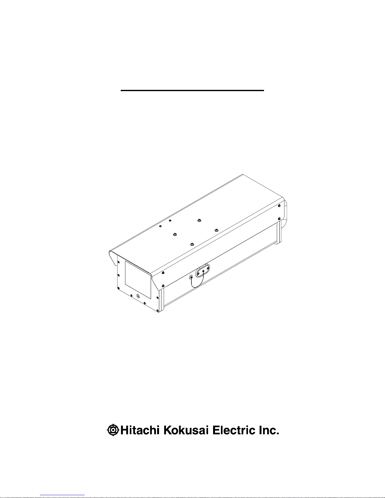
Outdoor Housing Camera
KP-D5010-S1
Operation manual
Thank you for purchase this fine Hitachi Kokusai Electric color CCD housing
camera. Before using the camera, please read this operation manual
carefully and keep this manual on file for ready reference in the future.
Page 2

Revision A June 27, 2011
2 / 49
IMPORTANT SAFETY INSTRUCTIONS
1. Read Instructions
All the safety and operating instructions should be read before the product is operated.
2. Retain Instructions
The safety and operating instructions should be retained for future reference.
3. Heed Warnings
All warnings on the product and the operating instructions should be adhered to.
4. Follow Instructions
All operating and use instructions should be followed.
5. Cleaning
Unplug this product from the wall outlet before cleaning. Do not use liquid cleaners or aerosol
cleaners. Use a damp cloth for cleaning.
6. Attachments
Do not use attachments not recommended by the product manufacturer as they may cause hazards.
7. Water and Moisture
Do not use this product near water - for example, near a bath tub, wash bowl, kitchen sink, or laundry
tub; in a wet basement; or near a swimming pool; and the like.
8. Accessories
Do not place this product on an unstable cart, stand, tripod, bracket, or table. The product may fall,
causing serious injury to a child or adult, and serious damage to the product. Use only with a cart,
stand, tripod, bracket, or table recommended by the manufacturer, or sold with the product. Any
mounting of the product should follow the manufacturer's instructions, and should use a mounting
accessory recommended by the manufacturer.
9. Moving
A product and cart combination should be moved with care.
Quick stops, excessive force, and uneven surfaces may cause the product and cart combination to
overturn.
10. Ventilation
Slots and openings in the cabinet are provided for ventilation and to ensure reliable operation of the
product and to protect it from overheating, and these openings must not be blocked or covered.
The openings should never be blocked by placing the product on a bed, sofa, rug, or other similar
surface. This product should not be placed in a built-in installation such as a bookcase or rack
unless proper ventilation is provided or the manufacturer's instructions have been adhered to.
11. Power Sources
This product should be operated only from the type of power source indicated on the marking label.
If you are not sure of the type of power supply to your home, consult your product dealer or local
power company. For products intended to operate from battery power, or other sources, refer to the
operating instructions.
12. Grounding or Polarization
This product is equipped with a three-wire grounding-type plug a plug having a third (grounding) pin.
This plug will only fit into a grounding-type power outlet. This is a safety feature. If you are unable
to insert the plug into the outlet, contact your electrician to replace your obsolete outlet. Do not
defeat the safety purpose of the grounding-type plug.
13. Power-Cord Protection
Power-supply cords should be routed to that they are not likely to be walked on or pinched by items
placed upon or against them, paying particular attention to cords at plug, convenience receptacles,
and the point where they exit from the product.
Page 3

Revision A June 27, 2011
3 / 49
14. Lightning
For added protection for this product during a lightning storm, or when it is left unattended and
unused for long periods of time, unplug it from the wall outlet. This will prevent damage to the
product due to lightning and power-line surges.
15. Overloading
Do not overload wall outlets, extension cords or integral convenience receptacles as this can result in
a risk of fire or electric shock.
16. Object and Liquid Entry
Never push objects of any kind into this product through openings as they may touch dangerous
voltage points or short-out parts that could result in a fire or electric shock. Never spill liquid of any
kind on the product.
17. Inflammable and Explosive Substance
Avoid using this product where there are gases, and also where there are inflammable and explosive
substances in the immediate vicinity.
18. Heavy Shock or Vibration
When carrying this product around, do not subject the product to heavy shock or vibration.
19. Servicing
Do not attempt to service this product yourself as opening or removing covers may expose you to
dangerous voltage or other hazards. Refer all servicing to qualified service personnel.
20. Damage Requiring Service
Unplug this product from the wall outlet and refer servicing to qualified service personnel under the
following conditions:
a. When the power-supply cord or plug is damaged.
b. If liquid has been spilled, or objects have fallen into the product.
c. If the product has been exposed to rain or water.
d. If the product does not operate normally by following the operating instructions. Adjust only those
controls that are covered by the operating instructions as an improper adjustment of other controls
may result in damage and will often require extensive work by a qualified technician to restore the
product to its normal operation.
e. If the product has been dropped or damaged in any way.
f. When the product exhibits a distinct change in performance-this indicates a need for service.
21. Replacement Parts
When replacement parts are required, be sure the service technician has used replacement parts
specified by the manufacturer or have the same characteristics as the original part.
Unauthorized substitutions may result in fire, electric shock, or other hazards.
22. Safety Check
Upon completion of any service or repairs to this product, ask the service technician to perform safety
checks to determine that the product is in proper operating condition.
23. Wall or Ceiling Mounting
The product should be mounted to a wall or ceiling only as recommended by the manufacturer.
24. Heat
The product should be situated away from heat sources such as radiators, heat registers, stoves, or
other products (including amplifiers) that produce heat.
Page 4

Revision A June 27, 2011
4 / 49
Contents
1. Introduction ............................................................................................................................... 5
2. Operating considerations Notes to users .............................................................................. 5
3. CCD characteristics ................................................................................................................. 5
4. Name and function of each section ........................................................................................ 6
5. Connection ................................................................................................................................ 8
6. A method of enclosing Nitrogen gas ...................................................................................... 9
7. Remote control protocol & command ................................................................................... 10
8. Setting Camera Menu description ......................................................................................... 24
9. Main specifications ................................................................................................................ 46
Page 5

Revision A June 27, 2011
5 / 49
1. Introduction
Hitachi KP-H5010 type outdoor housing camera is a surveillance camera which
built-in 1680mm (x55) power zoom lens and the single CCD brings high sensitivity
and high resolution picture. Besides power zoom function, auto focus function is
installed as standard. The removal effect of the fog is obtained by the Adaptive Fog
Reduction function.
2. Operating considerations Notes to users
1) Power supply
Use this camera with a 24VDC power supply. Time will be needed for about five seconds by the
time the camera works normally after turning on the power supply.
2) Handling
Do not attempt to remove cover.
3) Installing and storage
Avoid installing or storing the camera in the following environments.
a. Environments where combustible or corrosive gas exists.
b. Excessively warm or cold environment (Operating ambient temperature: -26 to 51℃).
c. Place subjected to excessive vibration or shock.
d. Environment exposed to strong electric or magnetic field.
e. Do not aim the camera lens at the sun.
f. Do not shoot strong light.
4) To obtain stable performance for long time
When the camera is used continuously for long time under high ambient temperature, the inside
electrical parts become deteriorated, resulting in shortening its life. To use the camera
continuously for long time, the highest temperature must be below 60℃.
5) Cleaning
a. Use a blower or a lens brush to remove dusts on the lens or the front glass.
b. Wipe dirt on the case off with dry soft cloth. If dirt is hardened, wipe them off with cloth
Moistened with neutral detergent liquid; wipe the cover with dry cloth.
c. Do not use benzene, thinner, alcohol, liquid cleaner or spray-type cleaner.
3. CCD characteristics
The following phenomenon is not defects but might occur due to characteristics of CCD.
1) Smear and blooming
This phenomenon occurs when strong light object (fluorescent lamp, car head light, strong
reflection of the sun light etc) is captured. Thin band at monitor screen is displayed above and
below of the strong light object. In this case, please change the camera angle in the position where
strong light does not enter in the camera.
2) Fixed pattern noise
Fixed pattern (vertical strip, white pixel spots, rough sprinkling) might be appearing on the monitor
screen, when camera is operated at high temperature. It becomes easy to see at high sensitivity
setting (AGC, electronic sensitivity improvement) of camera.
Page 6

Revision A June 27, 2011
6 / 49
3) Moire
When group of fine strips or stripped pattern is captured, additional stripped pattern (interference
inducted strips) which is not real might be seen on the monitor screen.
●It is necessary to note the following phenomenon specially.
4) Burning
When sun light or extremely strong light enters for a long time, the characteristics of the spectral
filter (color filter) of CCD image sensor might be deteriorated and the color of the corresponding
portion may change. Do not set or keep lens or CCD towards sun or extremely strong light
direction in either power on or off state.
5) White spot
Imperceptible white spots may rarely come up on the screen due to cosmic rays and so on. It
becomes easy to appear when the sensitivity of the camera is raised in the operation at the high
temperature.
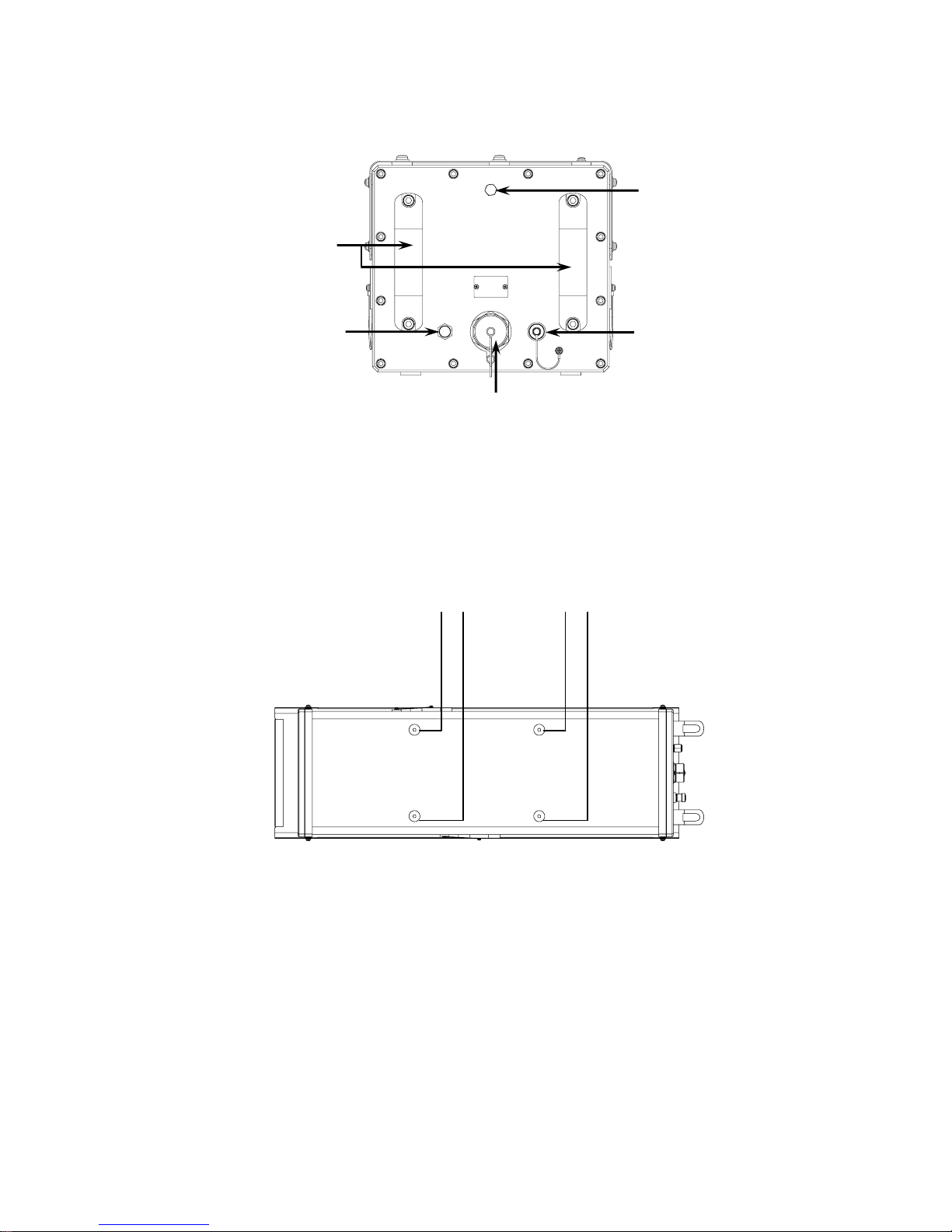
4. Name and function of each section
Air stopgap screw
M6×10SUS
Refer to
pag
e 9 (A method of enclosing Nitrogen gas).
A lid of adjusting lens iris
(H55ZAME-5F・PENTAX)
[Side view]
Page 7
Revision A June 27, 2011
7 / 49
[Back view]
Handle
When a built-in machinery is
taken out of the case, it
uses it.
Nitrogen gas
implantation bulb
Refer to page 9
(A method of enclosing
Nitrogen gas).
Relief bulb
Refer to page 9 (A method
of enclosin
g
Nitrogen gas).
Video output
(BNC connector)
REMOTE / Power supply connector
Refer to
pag
e 8.
[Bottom view]
Camera installation screw(4-1/4-20UNC [Corresponds to M&] )
Install these screws to the bottom of the camera.
Page 8
Revision A June 27, 2011
8 / 49
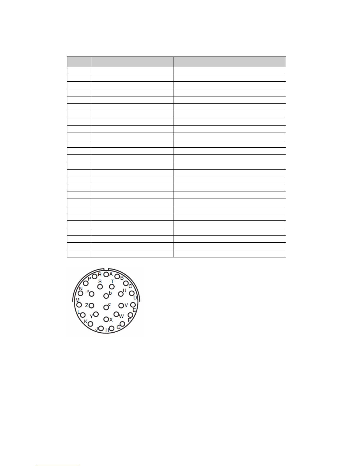
5. Connection
REMOTE / Power supply connector [ITT-Cannon, KPTR7P16-26P]
Pin Description Remark
A VIDEO GND Video signal ground
B VIDEO Video signal output
C GND 24VDC Return
D 24VDC DC POWER input (110 max)
E DAY CAM Tx Camera RS-232C serial data input
F DAT CAM Rx Camera RS-232C serial data output
G N.C. Do not connect
H N.C. Do not connect
J N.C. Do not connect
K N.C. Do not connect
L Tx/Rx GND Serial data ground
M N.C. Do not connect
N N.C. Do not connect
P N.C. Do not connect
R N.C. Do not connect
S N.C. Do not connect
T N.C. Do not connect
U N.C. Do not connect
V N.C. Do not connect
W N.C. Do not connect
X N.C. Do not connect
Y N.C. Do not connect
Z N.C. Do not connect
a N.C. Do not connect
b N.C. Do not connect
c N.C. Do not connect
Acceptable plug
ITT-Cannon, KPTR8F16-26S or, interchangeable goods.
Page 9
Revision A June 27, 2011
9 / 49
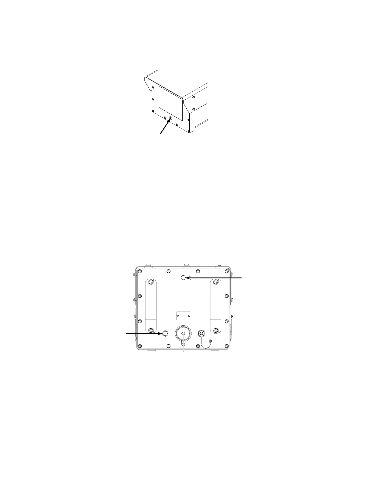
6. A method of enclosing Nitrogen gas
1) Exhaust air in the housing case
The closing screw for the air vomit hole under the front panel is taken, and air in the case is
exhausted.
2) Enclosing of Nitrogen gas
a) The Nitrogen gas implantation bulb screw is removed.
b) The chokedamp is enclosed from the Nitrogen gas implantation bulb.
c) Nitrogen is enclosed for five minutes or more on the following conditions, and air in the case is
Conditions: 7.2 psi (pound per square inch), 10L/min
This has aimed to raise the nitrogen gas concentration in the case.
d) The air vomit hole of the front panel will be closed with the screw in five minutes, and pressure in
the case is raised.
e) To keep the internal pressure to be constant when the internal pressure exceeds 7.25 psi,
nitrogen gas that is more extra than the relief valve is exhausted.
f) Finally, the cap of the Nitrogen gas implantation bulb is tightened and the end of work.
Air stopgap screw
M6×10SUS
Nitrogen gas implantation
bulb
Relief bulb
Page 10

Revision A June 27, 2011
10 / 49
7. Remote control protocol & command
1) Communications specifications
Sync system Start-stop sync
Bit rate 9600 bps
Data length 8 bits
Start bits 1
Stop bits 1
Parity None
2) Communication protocol
The communication protocol between the actuator and the housing camera is shown. (Figure 1)
The transmission command of one packet (11 bytes) is transmitted from the actuator to the housing
camera. The received command is recognized, and when it is executable, the command is
executed, and the housing camera transmits the reply command to the actuator.
Notes
The housing camera disregards the transmission command received from the reception of the
command to the transmission of the reply command.
Figure 1. Communication protocol
Actuate
Housing camera
The command is transmitted.
Command transmission
The command is received.
Is the destination address
the same as camera ID and is the
checksum same?
The reply data is not transmitted.
Are the command and data
the ranges of specification and
possible the command execution?
YES
The error is set to error code, and
the reply data is transmitted.
The reply data is received.
The command is executed.
‘0’ is set to error code, and the
reply data is transmitted.
YES
NO
NO
The reply data is received.
Page 11

Revision A June 27, 2011
11 / 49
3) Transmission command
Transmission command format
The command makes the fixed length in 11 bytes one packet and the data organization is as
follows.
Word 1 STX ( Start of Text A0h )
Word 2 Destination address ( 01h-1Fh )
Word 3 Source address ( 00h-1Fh )
Word 4 Command 1
Word 5 Command 2
Word 6 Data 1
Word 7 Data 2
Word 8 Data 3
Word 9 Data 4
Word 10 ETX (End of Text AFh )
Word 11 Checksum (Word2-9 is totaled and the 1's complement is taken).
How to request checksum
a) Word2-Word9 is totaled.
b) The value totaled from FFFFh is pulled.
c) Checksum that the last 2 digits requests.
Example: When the total of Word2-Word9 is 567h or A00h
FFFFh – 567h = FA98h -> 98h
FFFFh – A00h = F5FFh -> FFh
4) Reply command
Reply command informs actuator that housing camera recognizes and executed command for
transmission command transmitted from actuator. The destination address and the source address
of the transmission command are replaced and the reply command is transmitted.
Reply command format
Notes
As for data 1-3 of the reply command, the same data as the transmission command is sent back.
However, data is buried when there is reading information by the transmission command. The
housing camera transmits the transmission command, and it receives, and after it executes it, the
reply command is transmitted. It differs according to the command between that time, and when
the reply command is not transmitted for two seconds or more after the transmission command is
transmitted, it can be judged the failure of the housing camera.
Word 1 STX ( Start of Text A0h )
Word 2 Destination address ( 01h-1Fh )
Word 3 Source address ( 00h-1Fh )
Word 4 Command 1
Word 5 Command 2
Word 6 Data 1 Notes
Word 7 Data 2
Word 8 Data 3
Word 9 Error
Word 10 ETX (End of Text AFh )
Word 11 Checksum (Word2-9 is totaled and the 1's complement is taken).
Page 12

Revision A June 27, 2011
12 / 49
5) Error
Error (Word9) of the reply command shows the error of the housing camera.
Table 5.1 shows the content of the error.
Table 5.2 shows the generation factor and measures of the error.
Table 5.1 The content of the error.
Error Code Content of the error
7 bits The command is disregarded.
6 bits Initial busy
5 bits Camera unit failure
4 bits Not used
3 bits Not used
2 bits Not used
1 bits Not used
0 bits The Specification date is improper.
Table 5.2 the generation factor and measures of the error.
Content of the
error
Generation factor Measures
The command is
disregarded.
( Notes )
When the one shown in the following
was a busy, the transmission
command was transmitted
1) Initial busy
2) Lens busy
3) When camera menu opens
Please end the operation shown below or
transmit the transmission command after
operation ends.
Initial busy Initial busy
The camera is being initialized.
It waits until initial operation ends.
Camera unit
failure
At the state of the camera unit and
communicate impossible
Please control the zoom and focus by the
Zoom/Focus command.
The Specification
date is improper.
When the parameter of the
transmitted transmission command
is outside a specified range.
The parameter is set within the range of
specification.
Notes
The command disregard is not generated in the command (one that the command title starts by
Call) that reads information.
Page 13
Revision A June 27, 2011
13 / 49
6) The command is detailed
Details of the cereal command of housing camera KP-H5010 series are described.
a) Zoom / Focus command
It is a command that directs zoom / focus / One-push AF.
● Transmission command
● Reply command
● Parameter
The bit that controls Zoom, Focus, and One-Push AF shown in parameter vv and ww
operates by “1".
Present operation is assumed to be continuance for “1" of both of bits that direct a different
direction and it stops for both “0".
Command 1 Command 2 Data 1 Data 2 Data 3 Data 4
vv ww xx yy zz FFh
Command 1 Command 2 Data 1 Data 2 Data 3 Data 4
vv ww xx yy zz error
Bits vv ww xx yy zz
7 0 (Fixed) 0 (Fixed)
FFh
(Fixed)
FFh
(Fixed)
Focus speed
01h~08h
6 0 (Fixed)
Wide
5 0 (Fixed)
Te le
4 0 (Fixed) 0 (Fixed)
3 0 (Fixed) 0 (Fixed)
Zoom speed
01h~08h
2
One-Push AF
0 (Fixed)
1
Near
0 (Fixed)
0
Far
0 (Fixed)
Page 14

Revision A June 27, 2011
14 / 49
b) Set Current Position command
It is a command that does the presetting movement to the position in which zoom/focus were
specified.
● Transmission command
● Reply command
● Parameter
● Notes
The example of the registration procedure is shown in the following.
M YH-YL
a) 80h (start) FFFFh
b) 02h Zoom position parameters
c) 03h Focus position parameters
d) 40h End FFFFh
After the end is acquired, the presetting movement is done.
The working area is as shown in the following.
Zoom 0 – 255 (WIDE <-> TELE)
FOCUS 0 – 255 (FAR <-> NEAR)
The value of the WIDE edge and the TELE edge of optical system is different in each camera.
Please confirm the value of the edge by "Call Current Position command".
M Content YH-YL Content
02h Zoom 0000h – 00FFh
03h Focus 0000h – 00FFh
80h Start FFFFh
40h End FFFFh
Command 1 Command 2 Data 1 Data 2 Data 3 Data 4
00h 39h M YH YL FFh
Command 1 Command 2 Data 1 Data 2 Data 3 Data 4
00h 39h M YH YL error
Page 15

Revision A June 27, 2011
15 / 49
c) Call Current Position command
It is a command to which zoom/foci read position now.
● Transmission command
● Reply command
● Parameter
d) Set Camera Menu command
It is a command that operates the menu of the camera.
● Transmission command
● Reply command
● Parameter
M Content YH-YL Content
02h Zoom 0000h – 00FFh
03h Focus 0000h – 00FFh
Command 1 Command 2 Data 1 Data 2 Data 3 Data 4
00h 87h M FFh FFh FFh
Command 1 Command 2 Data 1 Data 2 Data 3 Data 4
00h 87h M YH YL error
Command 1 Command 2 Data 1 Data 2 Data 3 Data 4
00h 7Dh P FFh FFh FFh
Command 1 Command 2 Data 1 Data 2 Data 3 Data 4
00h 7Dh P FFh FFh error
P Content
00h Camera menu open switch
01h UP switch
02h DOWN switch
05h SET switch
10h UP & DOWN switch
Page 16

Revision A June 27, 2011
16 / 49
e) Set Extender command
It is a command that sets the extender function on/off of the lens.
● Transmission command
● Reply command
● Parameter
f) Call Extender command
It is a command to acquire the state of the lens of extender function.
● Transmission command
● Reply command
● Parameter
Command 1 Command 2 Data 1 Data 2 Data 3 Data 4
00h 61h S FFh FFh FFh
Command 1 Command 2 Data 1 Data 2 Data 3 Data 4
00h 61h S FFh FFh error
S Content
00h Extender OFF
01h Extender ON
Command 1 Command 2 Data 1 Data 2 Data 3 Data 4
00h FDh S FFh FFh FFh
Command 1 Command 2 Data 1 Data 2 Data 3 Data 4
00h FDh S FFh FFh error
S Content
00h Extender OFF
01h Extender ON
Page 17

Revision A June 27, 2011
17 / 49
g) Set Cam_Cmd command
It is a command that sets the camera.
● Transmission command
● Reply command
● Parameter
C: Relativity Number (R No.)
D1: Data 1
D2: Data 2
D3: Data 3
Please refer to “Camera Command List” on page 18 for details.
h) Call Cam_Cmd command
It is a command to acquire the state of the camera.
● Transmission command
● Reply command
● Parameter
C: Relativity Number (R No.)
D1: Data 1
D2: Data 2
D3: Data 3
Please refer to “Camera Command List” on page 18 for details.
Command 1 Command 2 Data 1 Data 2 Data 3 Data 4
00h DBh C D1 D2 D3
Command 1 Command 2 Data 1 Data 2 Data 3 Data 4
00h DBh C D1 D2 D3
Command 1 Command 2 Data 1 Data 2 Data 3 Data 4
00h DDh C D1 D2 D3
Command 1 Command 2 Data 1 Data 2 Data 3 Data 4
00h DDh C D1 D2 D3
Page 18

Revision A June 27, 2011
18 / 49
7) Camera Command List
a) Write command (Set data)
Item C(R. No) D1 D2 D3
Light control mode AVERAGE
(*)
1B 00 00 00
BLC 1B 01 00 00
PEAK/AVE 1B 02 00 00
AERA select No.
(LIGHT CONTROL: BLC)
Image of area
NO.1
(*)
1C 00 00 00
NO.2 1C 01 00 00
NO.3 1C 02 00 00
NO.4 1C 03 00 00
NO.5 1C 04 00 00
NO.6 1C 05 00 00
NO.7 1C 06 00 00
NO.8 1C 07 00 00
NO.9 1C 08 00 00
Ratio of Peak & Average
(LIGHT CONTROL :PEAK/AVE)
0/100 39 00 00 00
15/ 85
(*)
39 01 00 00
30/ 70 39 02 00 00
50/ 50 39 03 00 00
75/ 25 39 04 00 00
100/ 0 39 05 00 00
Video Level
(LEVEL)[ 00–FF ]
Min 0C 00 00 00
| 0C ** 00 00
Mid
(*)
0C 80 00 00
| 0C ** 00 00
Max 0C FF 00 00
AIE mode OFF
(*)
63 00 00 00
LOW 63 01 00 00
MID 63 02 00 00
HIGH 63 03 00 00
AGC mode OFF 06 01 00 00
ON
(*)
06 00 00 00
Notes: If the AGC setting is switched to turning off when B/W mode sets AUTO, B/W mode is
Compulsorily turned off.
FIX. GAIN (AGC: OFF)
FIX. GAIN [1dB-51dB]
Min
(*)
68 07 00 00
| 68 ** 00 00
Max 68 39 00 00
AGC LIMIT (AGC: ON)
AGC LIMIT [-6dB-51dB]
Min
(*)
4d 00 00 00
| 4d ** 00 00
Max 4d 39 00 00
(*)
: Factory setting
Page 19

Revision A June 27, 2011
19 / 49
Item C (R. No) D1 D2 D3
DNR OFF 3E 00 00 00
AUTO(LOW) 3E 01 00 00
AUTO(HIGH)
(*)
3E 02 00 00
Shutter speed 1/60 s
(*)
08 00 00 00
1/100 s 08 01 00 00
1/250 s 08 02 00 00
1/500 s 08 03 00 00
1/1000 s 08 04 00 00
1/2000 s 08 05 00 00
1/4000 s 08 06 00 00
1/10000 s 08 07 00 00
1/20000 s 08 08 00 00
1/50000 s 08 09 00 00
1/100000 s 08 0A 00 00
AES 08 0B 00 00
1/1000s[AES&LENS
]
08 0C 00 00
1/2000s[AES&LENS
]
08 0D 00 00
1/5000s[AES&LENS
]
08 0E 00 00
Notes
1) When SENS UP: AUTOx** is set, only 1/60, 1/100 can be set. When other transmitting, if
compulsorily becomes 1/60.
2) When SENS UP: MANUx** is set, it becomes 1/60 fixation.
B/W mode OFF
(*)
64 00 00 00
ON 64 01 00 00
AUTO(HI) 64 02 00 00
AUTO(MID) 64 03 00 00
AUTO(LOW) 64 04 00 00
Notes: When AGC: OFF is set, only turning off or turning on can be set.
BURST OFF 9B 00 00 00
ON
(*)
9B 01 00 00
Digital zoom OFF
(*)
37 01 00 00
ON 37 00 00 00
Digital zoom operation WIDE 38 01 00 00
TELE 38 00 00 00
LENS type select DC A9 00 00 00
VIDEO A9 01 00 00
Polarity POSITIVE
(*)
01 00 00 00
NEGATIVE 01 01 00 00
MIRROR OFF
(*)
A3 00 00 00
ON A3 01 00 00
(*)
: Factory setting
Page 20

Revision A June 27, 2011
20 / 49
Item C (R. No) D1 D2 D3
SENS UP mode OFF
(*)
1A 00 00 00
AUTO x 2 1A 01 00 00
AUTO x 4 1A 02 00 00
AUTO x 6 1A 03 00 00
AUTO x 8 1A 04 00 00
AUTO x10 1A 05 00 00
AUTO x12 1A 06 00 00
AUTO x16 1A 07 00 00
AUTO x32 1A 08 00 00
AUTO x64 1A 09 00 00
AUTO x128 1A 0A 00 00
OFF 1A 0B 00 00
MANU x 2 1A 0C 00 00
MANU x 4 1A 0D 00 00
MANU x 6 1A 0E 00 00
MANU x 8 1A 0F 00 00
MANU x10 1A 10 00 00
MANU x12 1A 11 00 00
MANU x16 1A 12 00 00
MANU x32 1A 13 00 00
MANU x64 1A 14 00 00
MANU x128 1A 15 00 00
MANU x192 1A 16 00 00
MANU x256 1A 17 00 00
MANU x320 1A 18 00 00
MANU x384 1A 19 00 00
MANU x448 1A 1A 00 00
MANU x512 1A 1B 00 00
Notes: It compulsorily becomes 1/60 if it transmits excluding SENS UP turning off when setting it
excluding SHUTTER SPEED: 1/60 and 1/100.
White Balance Mode ATW
(*)
04 00 00 00
AWC 04 01 00 00
MANUAL 04 02 00 00
ATW RANGE NORMAL
(*)
62 00 00 00
SPECIAL 62 01 00 00
(*)
: Factory setting
Page 21

Revision A June 27, 2011
21 / 49
Item C (R. No) D1 D2 D3
WB AREA mode OFF
(*)
3B 00 00 00
ON 3B 01 00 00
WB area No.
(WB AREA: ON)
Image of area
NO.1
(*)
3C 00 00 00
NO.2 3C 01 00 00
NO.3 3C 02 00 00
NO.4 3C 03 00 00
NO.5 3C 04 00 00
NO.6 3C 05 00 00
NO.7 3C 06 00 00
NO.8 3C 07 00 00
NO.9 3C 08 00 00
AWC PRESET START 40 00 00 00
Notes: The WHITE BALANCE mode: When this command is transmitted at AWC, the white
balance is taken heart.
R-GAIN OFFSET for AWC
[00-FF]
Min 46 00 00 00
| 46 ** 00 00
Mid
(*)
46 80 00 00
| 46 ** 00 00
Max 46 FF 00 00
B-GAIN OFFSET for AWC
[00-FF]
Min 47 00 00 00
| 47 ** 00 00
Mid
(*)
47 80 00 00
| 47 ** 00 00
Max 47 FF 00 00
R-GAIN for MANUAL [00-FF] Min 0D 00 00 00
| 0D ** 00 00
Mid
(*)
0D 80 00 00
| 0D ** 00 00
Max 0D FF 00 00
B-GAIN for MANUAL [00-FF] Min 0E 00 00 00
| 0E ** 00 00
Mid
(*)
0E 80 00 00
| 0E ** 00 00
Max 0E FF 00 00
GAMMA OFF 14 00 00 00
ON
(*)
14 01 00 00
HIGH 14 02 00 00
Resolution NORMAL
(*)
59 00 00 00
HIGH 59 01 00 00
(*)
: Factory setting
Page 22

Revision A June 27, 2011
22 / 49
Item C (R. No) D1 D2 D3
CHROMA
[00-B2]
Min 16 00 00 00
| 16 ** 00 00
Mid
(*)
16 80 00 00
| 16 ** 00 00
Max 16 B2 00 00
DETAIL
[00-FF]
Min 15 00 00 00
| 15 ** 00 00
Mid
(*)
15 80 00 00
| 15 ** 00 00
Max 15 FF 00 00
FOG Correction OFF
(*)
18 00 00 00
AUTO 18 01 00 00
MANUAL 18 02 00 00
Scene file switch File1
(*)
A8 00 00 00
File2 A8 01 00 00
File3 A8 02 00 00
File4 A8 03 00 00
File5 A8 04 00 00
CAMERA RESET 4F 00 00 00
(*)
: Factory setting
Page 23

Revision A June 27, 2011
23 / 49
b) Read command (Read data)
Item C (R. No) D1 D2 D3
Light control mode 1B 00 00 00
AERA select No. (LIGHT CONTROL: BLC) 1C 00 00 00
Ratio of Peak & Average (LIGHT CONTROL :PEAK/AVE) 39 00 00 00
Video Level 0C 00 00 00
AIE mode 63 00 00 00
AGC mode 06 00 00 00
FIX. GAIN (AGC: OFF) 68 00 00 00
AGC LIMIT (AGC: ON) 4d 00 00 00
DNR 3E 00 00 00
SHUTTER SPEED 08 00 00 00
B/W MODE 64 00 00 00
BURST 9B 00 00 00
Digital zoom 37 00 00 00
LENS type select A9 00 00 00
Polarity 01 00 00 00
MIRROR A3 00 00 00
SENS UP 1A 00 00 00
White balance mode 04 00 00 00
ATW RANGE 62 00 00 00
WB AREA 3B 00 00 00
WB area no. 3C 00 00 00
R-GAIN OFFSET for AWC [00-FF] 46 00 00 00
B-GAIN OFFSET for AWC [00-FF] 47 00 00 00
R-GAIN for MANUAL [00-FF] 0D 00 00 00
B-GAIN for MANUAL [00-FF] 0E 00 00 00
GAMMA 14 00 00 00
Resolution 59 00 00 00
CHROMA 16 00 00 00
DETAIL 15 00 00 00
FOG Correction 18 00 00 00
Scene file switch A8 00 00 00
Page 24

Revision A June 27, 2011
24 / 49
8. Setting Camera Menu description
The camera setting and adjustments can be changed to meet the using conditions. Use the setting
menu displayed on the monitor screen to check and change the settings and adjustments. The
setting menu is comprised as follows.
Setting camera menu composition
Setting camera menu composition
The camera setting menu is operated by the camera menu command.
● Transmission command
● Reply command
● Parameter
・Display character setting
・Display position setting
White balance mode
setting
・Auto tracking white balance
(ATW)
・Preset white balance
(AWC)
・Manual white balance
(MANUAL)
・
Color level adjustment,
detail, black level and
digital zoom setting etc
Enhancement menu (page 24)
・BLC on/off and area setting
・Video level adjustment
AGC setting (page13)
Shutter speed setting (page 15)
Sensitivity enhancement setting
(page 16)
Color-B/W selection (page 17)
AGC mode setting
White balance setting (page 18)
Scene file setting (page 9)
Light control menu (page10)
Camera title setting (page 22)
Main menu
(page 9 )
Sub menu (page 28)
・Lens setting etc
・Bursts setting
Command 1 Command 2 Data 1 Data 2 Data 3 Data 4
00h 7Dh P FFh FFh FFh
Command 1 Command 2 Data 1 Data 2 Data 3 Data 4
00h 7Dh P FFh FFh error
P Content Operation
00h Camera menu open switch The camera setting menu is opened.
01h UP switch Shift the cursor in the upward direction or increase an
adjustment value
02h DOWN switch Shift the cursor in the downward direction or decrease
an adjustment value
05h SET switch It uses it for the mode change and the menu
movement.
10h UP & DOWN switch When the setting or the adjusted value is returned to
the factory setting value, it uses it.
Page 25

Revision A June 27, 2011
25 / 49
Main menu operation
1) When the Open command is transmitted, the MAIN MENU is displayed.
2)
Check the current settings at the main menu.
3) The cursor [
>] moves up (down) by the UP (DOWN) command.
4) When the SET command is transmitted by the item with the
↵mark, it shifts to the following menu.
5) The cursor is moved to the position of END under the screen when there are no alterations
necessary, and the SET command is transmitted and it returns it to a usual taking picture screen.
6) Changed settings are stored in the camera memory (EEPROM) and restored at the power on.
Scene file setting
Scene file is a function to record various mode settings and the adjusted values of the camera at file.
1) The OPEN command is transmitted and MAIN MENU is opened.
2) Use UP or Down commands to move the cursor [
>] to MAIN MENU.
3) The scene file setting data blinks. In this state, Scene file № is changed by the SET command.
Set command:FILE1→FILE2→FILE3→FILE4→FILE5 (Factory setting is FILE1.)
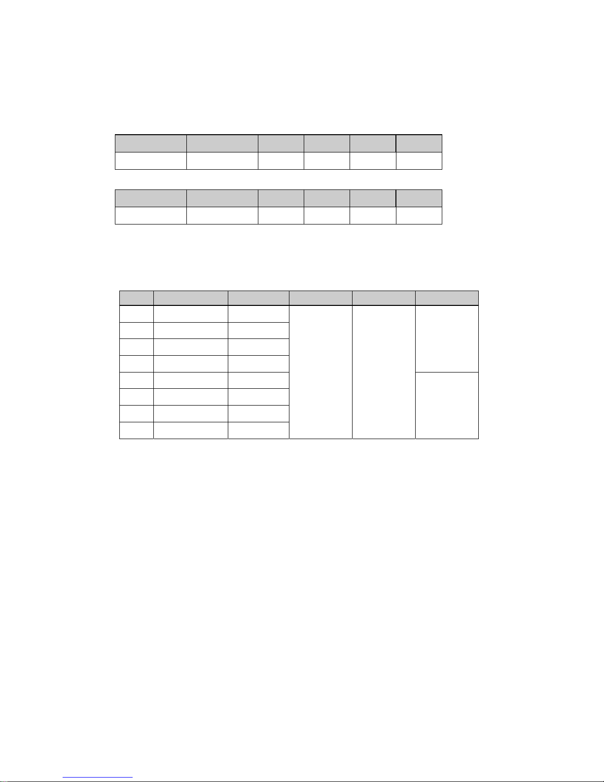
Scene file factory setting
Scene file No. 1 2 3 4 5
High sensitivity
setting
Fog adjustment
(color)setting
Fog adjustment
(B/W)setting
Back light
correction setting
Stored high
sensitivity setting
LIGHT CONTROL
MODE AVERAGE AVERAGE AVERAGE BLC AVERAGE
AREA
--- --- ---
NO.1
---
AIE OFF OFF OFF MID OFF
AGC 51 31 31 31 51
SENS UP OFF OFF OFF OFF AUTOx16
B/W MODE OFF OFF ON OFF OFF
FOG ADJUST OFF AUTO AUTO OFF OFF
Main menu
>◆ MAIN MENU ◆(FILE1)
LIGHT CONTROL:AVE
↵
AGC :ON
↵
SHUTTER SPEED:1/6 0
SENS UP :OFF
B/W MODE :OFF
↵
WHITE BALANCE:ATW
↵
CAMERA TITLE :OFF ↵
ENHANCE ↵
SUB MENU
↵
END
……Scene file setting
……Light control menu
……AGC setting menu
……Shutter speed setting
……Sensitivity enhancement Setting
……Color-B/W mode setting
……White balance setting
……Camera title menu
……Enhance setting menu
……Sub menu
……End (Menu display off)
Page 26

Revision A June 27, 2011
26 / 49
Light control menu
The method of the AE (Auto-Iris, AGC, Sens-UP-Auto) function is set with LIGHT CONTROL.
1) Light control mode setting
a) The OPEN command is transmitted and MAIN MENU is opened.
b) Use UP or Down commands to move the cursor [
>] to LIGHT CONTROL.
c) Under such a condition, when the SET command is transmitted, LIGHT CONTROL MENU is
displayed.
d) When the cursor [
>] is at MODE, in this state, MODE is changed by the SET command.
Set command:AV ERAGE→BLC→PEAK/AVE
AVE (Average mode)
This mode measures the average luminance of the entire screen and controls the exposure level.
This is default mode.
BLC (Back Light Control mode)
This mode controls the exposure level at the luminance level of the specified area. (It can be
selected from 9 areas).
PK/AVE (Peak/Average mode)
This mode uses the peak luminance together with average and controls the exposure level. (The
ratio of peak level and average level can be changed.)
2) Video level adjustment
The optimum video level is to factory setting (000). If necessary, the level can be changed as
foIIows.
a) Use UP or Down commands to move the cursor [
>] to LEVEL.
b) The adjusted value changes into the blinking if the SET command is transmitted.
c) The adjusted value is changed when the UP or DOWN command is transmitted at this time and
the
cutting change video level is changed.
Adjustment value range : -128~000~+127
◆ LIGHT CONTROL MENU ◆
>MODE :AVERAGE
LEVEL : 000
AIE : OFF
↑
RET
END
……Light control mode display
……Video level adjustment(-128~000~+127)
……AIE mode
……Return to Main menu
……End (Menu display off)
Light control menu [AV ER AG E]
◆ LIGHT CONTROL MENU ◆
>MODE :AVERAGE
LEVEL : 000
AIE : OFF
↑
RET
END
……Light control mode display
……Video level adjustment(-128~000~+127)
……AIE mode
……Return to Main menu
……End (Menu display off)
Light control menu [AV ER AG E]
Page 27

Revision A June 27, 2011
27 / 49
d) It returns to the factory setting (000) when the UP&DOWN command is transmitted.
e) Blinking stops if the SET command is transmitted, the set value is fixed, and the cursor [
>]
moves to AIE.
NOTE: In case of using video signal input type auto iris lens
Lens iris operates by the sensitivity setting of lens regardless light control mode setting.
When the LENS TYPE setting of the camera is set to VIDEO, the lens sensitivity
setting adjustment gauge (Lev/Ref) is displayed on LIGHT CONTROL MENU.
Set the sensitivity on the lens such that the Video output level setting [Lev] should not fall
less than the standard level of the exposure control [Ref].
If it is adjusted lower than the value of [Ref], the repetition phenomenon of the lens iris
control and the AGC control (Hunting) might be generated.
3) Back light control mode setting
The lens iris closes in response to brightness when strong light or sun light is hitting the spot
besides the place to be observed, and the subject of interest becomes dark. This mode is used to
avoid darkening of subject of interest in such condition.
a) Use UP or Down commands to move the cursor [
>] to MODE.
b) It cuts in the following menu display when the SET command is transmitted and BLC is set and
it changes.
c) When the cursor [
>] is matched to AREA SELECT, and the SET command is transmitted,
the detection area select menu that selects the detection area is displayed.
◆ LIGHT CONTROL MENU ◆
>MODE :AVERAGE
Lev
|||||||||||||||||||||||||||||||||||||||||||||||・・
・・・・・・・・・・・・・・・・・・・・・
Ref
||||||||||||||||||||||||||||||||||||||||||||||・・・
・・・・・・・・・・・・・・・・・・・・
LEVEL : 000
AIE :OFF
……Light control mode display
……Video output level gauge
……Light control standard level gauge
……Video level adjustment(-128~000~+127)
……AIE mode
……Return to Main menu
……End (Menu display off)
Light control menu [AV ER AG E]
◆ LIGHT CONTROL MENU ◆
>MODE :BLC
AREA SELECT:NO.1
↵
LEVEL : 000
AIE : OFF
↑
RET
END
……Light control mode display
……Photomatric Area select : No.1~9
……Video level adjustment(-128~000~+127)
……AIE mode
……Return to Main menu
……End(Menu display off)
Light control menu [BLC]
AREA(BLC)
NO.1
┏━━━━━━┓
┃ ┃
┃ ┃
┗━━━━━━┛
Detection area setting menu
Area position and number
6 5
4
2
1 3
7
8 9
Page 28

Revision A June 27, 2011
28 / 49
d) There are 9 light detection areas that can be selected by the Up or Down command. Select the
areas from No. 1 to 9 such that subject of interest is entered in the selected area.
It is set to No.1 in factory setting.
Up command: 1→2→3→4→5→6→7→8→9
Down button: 9→8→7→6→5→4→3→2→1
e) The setting is fixed when the SET command is transmitted and it returns to LIGHT CONTROL
MENU.
Note
a) The backlighting compensation of a central emphasis is set at the time of electronic
zoom operation.
b) The back light control mode does not operate in case of using video signal input type auto
iris lens.
4) Peak/Average mode setting
When there is strong light spot within the image, the near by area of spot may have overexposure
and the subject might not be confirmed. This mode is used when taking picture under such
condition. It can control overexposure in such conditions.
a) Use UP or Down commands to move the cursor [
>] to MODE.
b) It cuts in the following menu display when the SET command is transmitted and PEAK/AVE is
set and it changes.
c) The ratio of peak /average cuts when the cursor [
>] is matched to PK/AV, and the SET command
is transmitted and it changes.
Set command: 0/100→ 15/ 85→ 30/ 70→ 50/ 50→ 75/ 25→ 100/0
The response to spot light increases with increment in peak value. Factory setting is 15/85.
◆ LIGHT CONTROL MENU ◆
MODE :PEAK/AVE
>PK/AV : 15/ 85
LEVEL : 000
AIE : OFF
↑
RET
END
……Light control mode display
……Peak level/Average
……Video level adjustment(-128~000~+127)
……AIE mode
……Return to Main menu
……End (Menu display off)
Light control menu [PEAK/AVE]
Page 29

Revision A June 27, 2011
29 / 49
5) AIE mode setting
AIE is a function to correct brightness of the part that has darkened as a result of over exposure
control by BLC and PEAK/AVE.
a) Use UP or Down commands to move the cursor [
>] to AIE.
b) The AIE mode cuts when the SET command is transmitted and it changes.
Set command: OFF→LOW→MID→HIGH
OFF: AIE is inactive. It is set for AIE in factory setting.
LOW, MID, HIGH: AIE is effective. The enhancement level of the part that has darkened is
changed to LOW, MID, HIGH.
Note
The part that has darkened is corrected brightness by the enhancement level increment, but the
picture might be noisy. Therefore, set the enhance level with taking picture conditions.
AGC menu
1) AGC mode setting
a) The OPEN command is transmitted and MAIN MENU is opened.
b) Use UP or Down commands to move the cursor [
>] to AGC.
c) Under such a condition, when the SET command is transmitted, AGC MENU is displayed.
d) When the SET command is transmitted, the AGC mode is changed.
Set command: ON→OFF
ON: Automatically changes the video level within a range of the AGC limit as appropriate
according to the brightness of subject. AGC is set to ON in factory setting.
OFF: Always sets a fixed video level from the [FIX. GAIN].
2) AGC limit setting (AGC ON)
a) Use UP or Down commands to move the cursor [
>] to AGC LIMIT.
b) AGC limit gauge cuts in the blinking when the SET command is transmitted and it changes.
c) Under such a condition, the maximum amplification level is set by the UP or DOWN command.
Maximum amplification level AGC LIMIT can be set within the range of 0~+51.
d) Under such a condition, when the SET command is transmitted, a set value is fixed.
The blinking display ends and the cursor moves to DNR.
◆ AGC MENU ◆
>MODE :ON
AGC LIMIT :+31
0・・・・・・・・●・・・・・・51
DNR :OFF
RET
END
……AGC mode display
……AGC lmit (0~+51)
……AGC limit gauge
……Digital Noise Reduction(DNR)dis play
……Return to Main menu
……End (Menu display off)
AGC setting menu (ON)
Page 30

Revision A June 27, 2011
30 / 49
3) FIX Gain setting (AGC OFF)
a) Use UP or Down commands to move the cursor [
>] to MODE.
b) It changes into the following display if the SET command is transmitted, and the mode is turned
OFF.
c) Use UP or Down commands to move the cursor [
>] to FIX GAIN.
b) FIX gain gauge cuts in the blinking when the SET command is transmitted and it changes.
c) Under such a condition, the maximum amplification level is set by the UP or DOWN command.
Fixed amplification level FIX GAIN can be set within the range of -6~+51.
d) Under such a condition, when the SET command is transmitted, a set value is fixed.
The blinking display ends and the cursor [
>] moves to DNR.
Note
At high AGC LIMIT/FIX. GAIN, sensitivity increases, but noise becomes more apparent.
4) Digital Noise Reduction (DNR) setting
It is a function to reduce the noise element generated by AGC gain increment.
a) Use UP or Down commands to move the cursor [
>] to DNR.
b) It changes if the cursor is matched to DNR by the SET command is transmitted.
SET command: OFF → AUTO-LOW → AUTO-MID → AUTO-HIGH
OFF: DNR is inactive.
AUTO-*
LOW: Movement priority mode
MID: Middle mode
HIGH: Image quality priority mode
DNR is set to AUTO-LOW in factory setting
◆ AGC MENU ◆
>MODE :OFF
FIX GAIN :+31
-6・・・・・・・・●・・・・・・51
DNR :OFF
RET
END
……AGC mode display
……AGC lmit (-6~+51)
……AGC limit gauge
……Digital Noise Reduction(DNR)dis play
……Return to Main menu
……End (Menu display off)
AGC setting menu (OFF)
Page 31

Revision A June 27, 2011
31 / 49
Shutter speed
1) Shutter speed setting
a) The OPEN command is transmitted and MAIN MENU is opened.
b) Use the Up and Down buttons to move the cursor [
>] to SHUTTER SPEED. Shutter speed setting
data flashes. In this state, push the Set button to change the shutter speed as follows.
Set command: 1/60(1/50 PAL)→1/100(1/120 PAL)→1/250→1/500→1/1000→1/2000→1/5000
→1/10000→1/20000→1/50000→1/100000→AES→AES&LENS(1/1000)
→AES&LENS(1/2000)→AES&LENS(1/5000)
Factory setting: 1/60 (1/50)
2) Auto Electric Shutter (AES)
AES is a function to automatically adjust the electronic shutter speed according to the amount of
incident light and keep the image level constant.
Note
a) When using a DC type/VIDEO type auto iris lens, fix the iris to fully open.
b) When the following phenomenon occurs while AES is operating, change to different shutter
speed. The following are not defects.
・Strong smear or blooming occurs in the scene.
・Screen flicker or coloration occurs.
Main menu
◆ MAIN MENU ◆(FILE1)
LIGHT CONTROL:AVE
↵
AGC :ON
↵
>SHUTTER SPEED:1/60
SENS UP :OFF
B/W MODE :OFF
↵
WHITE BALANCE:ATW
↵
CAMERA TITLE :OFF ↵
ENHANCE ↵
SUB MENU ↵
END
……Scene file setting
……Light control menu
……AGC setting menu
……Shutter speed setting
……Sensitivity enhancement Setting
……Color-B/W mode setting
……White balance setting
……Camera title menu
……Enhance setting menu
……Sub menu
……End (Menu display off)
Page 32

Revision A June 27, 2011
32 / 49
Sensitivity enhancement setting (SENS UP)
SENS UP is a sensitivity enhancement function that increases the CCD exposure time (shutter
speed) greater than 1/60 or 1/50 seconds of the standard time.
a) The OPEN command is transmitted and MAIN MENU is opened.
b) Use the Up and Down buttons to move the cursor [
>] to SENS UP. Sens up setting data flashes.
In this state, push the SET command to change the shutter speed as follows.
Set command: OFF→AUTOx2→AUTOx4→AUTOx6→AUTOx8→AUTOx10→AUTOx12
→AUTOx16→AUTOx32→AUTOx64→AUTOx128→OFF→MANU x2
→MANUx4→MANUx6→MANx8→MANUx10→MANUx12→MANUx16
→MANUx32→MANUx64→MANUx128→MANUx192→MANUx256
→MANUx320→MANUx384→MANUx448→MANUx512→1/10000→1/20000
→1/50000→1/100000→AES→AES&LENS(1/1000)→AES&LENS(1/2000)
→AES&LENS(1/5000)
Factory setting: 1/60 (1/50)
Relation of SENS UP setting and SHUTTER SPEED
SENS UP Setting
OFF AUTO MANU
SHUTTER
SPEED
1/60 (1/50) 1/60(1/50) 1/60(1/50) 1/60(1/50)
1/100(1/120) 1/100(1/120) 1/100(1/120) 1/60(1/50)
1/250
|
1/100000
1/250
|
1/100000
1/60(1/50) 1/60(1/50)
AES AES AES 1/60(1/50)
a) SHUTTER SPEED can not be changed to be other than 1/60 or 1/100 when SENS UP is AUTO
and MANU.
b) If SHUTTER SPEED setting is other than 1/60, 1/100 or AES, it is changed to 1/60 when the
SENS UP setting is changed to AUTO.
c) If SHUTTER SPEED setting is other than 1/60, it is changed to 1/60 when the SENS UP setting
is changed to MANU.
Main menu
◆ MAIN MENU ◆(FILE1)
LIGHT CONTROL:AVE
↵
AGC :ON
↵
SHUTTER SPEED:1/60
>SENS UP :OFF
B/W MODE :OFF
↵
WHITE BALANCE:ATW
↵
CAMERA TITLE :OFF ↵
ENHANCE ↵
SUB MENU ↵
END
……Scene file setting
……Light control menu
……AGC setting menu
……Shutter speed setting
……Sensitivity enhancement Setting
……Color-B/W mode setting
……White balance setting
……Camera title menu
……Enhance setting menu
……Sub menu
……End (Menu display off)
Page 33

Revision A June 27, 2011
33 / 49
Note
a) Sensitivity goes up when the sensitivity enhancement is increased, but when taking picture of
subject with a fast movement, the blur of the image (after image) grows too.
b) Sensitivity goes up when the sensitivity enhancement is increased, but the noise of image is
also increases. Morever, if the surrounding temperature is high, amount of the noise might
increase.
c) White pixel might be there at the time of sensitivity enhancement operation. This is not a
defect.
d) Turn ON the DNR when the noise stands out with sensitivity improvement. The afterimage
might stand out when taking picture of subject with a fast movement. At that time, switch
the DNR setting to OFF.
Color-B/W selection (B/W mode)
Sensitivity enhancement by Color-B/W selection (B/W mode)
1) MODE setting
a) The OPEN command is transmitted and MAIN MENU is opened.
b) Use the Up and Down buttons to move the cursor [
>] to B/W MODE.
c) It changes into the following display if the SET command is transmitted, B/W MODE MENU is
displayed.
d) Use the Up and Down buttons to move the cursor [
>] to MODE.
e) In this state, push the SET command to change the shutter speed as follows.
Set command: OFF→ON→AUTO(H)→AUTO(M)→AUTO(L)
OFF: This mode is of color picture. (factory setting)
ON: This mode is of black and white picture.
AUTO: In this mode, color image black and white image is changed automatically
according to the brightness of subject. It is the brightness (picture level) that
displayed inside ( ) when color image is changed to black and white image.
Main menu
◆ MAIN MENU ◆(FILE1)
LIGHT CONTROL:AVE
↵
AGC :ON
↵
SHUTTER SPEED:1/60
SENS UP :OFF
>B/W MODE :OFF ↵
WHITE BALANCE:ATW
↵
CAMERA TITLE :OFF ↵
ENHANCE ↵
SUB MENU ↵
END
……Scene file setting
……Light control menu
……AGC setting menu
……Shutter speed setting
……Sensitivity enhancement Setting
……Color-B/W mode setting
……White balance setting
……Camera title menu
……Enhance setting menu
……Sub menu
……End (Menu display off)
◆ B/W MENU ◆
>MODE :OFF
BURST :ON
MONO→COLOR : 010
COLORR→MONO : 005
RET
END
……B/W mode
……Burst setting
……
B/W to color mode change time setting
……Color to B/W mode change time setting
……Return to Main menu
……End (Menu display off)
B/W setting menu
Page 34

Revision A June 27, 2011
34 / 49
AUTO(H): About 70% or less of proper value
AUTO(M): About 50% or less of proper value
AUTO(L): About 35% or less of proper value
When switching from black and white picture to color picture, AGC gain or SENS UP refers to
magnification. Therefore, when AGC setting is OFF and furthermore, SENS UP setting is
OFF/MANU, AUTO setting of BW MODE can not be used.
2) Setting of switching time [MONO→COLOR]
a) The UP or DOWN command is transmitted and the cursor is matched to MONO→COLOR.
b) The setup data display of MONO→COLOR blinks when the SET command is transmitted.
c) Under such a condition, the time setting that changes from B/W into the COLOR when the UP
or DOWN command is transmitted can be adjusted.
Adjustment value range:001~030 (unit: second) Factory setting is 010.
3) Setting of switching time [COLOR→MONO]
a) The UP or DOWN command is transmitted and the cursor is matched to COLOR→MONO.
b) The setup data display of COLOR→MONO blinks when the SET command is transmitted.
c) Under such a condition, the time setting that changes from COLOR into the B/W when the UP
or DOWN command is transmitted can be adjusted.
Adjustment value range:001~030 (unit: second)) Factory setting is 005.
Color/BW switching
The camera CCD responds to infrared light (700~1000nm) that is invisible to the human
eye. Normal color camera uses an IR cut filter to remove the infrared components in order to
bring it close to human eye. This condition is used for color image. In case of black and white
image, the IR cut filter is removed in order to making it more sensitive for infrared light.
Note
a) When using infrared light, the switching of color picture ⇔ black and white picture might
occur according to the picture shooting conditions such as strong light or the distance
from the subject is short. In this case, decrease the brightness of the illumination.
b) Under the picture shooting condition without the infrared light, sensitivity is not increased
even if it switches to a monochrome image.
c) Focal plane of the lens is different for visible light (color picture) and black and white picture.
Therefore, adjusted focus for color picture shifts when mode switches to black and white
picture. Use the lens sensitive to infrared light, in case of BW MODE.
◆ B/W MENU ◆
>MODE :OFF
BURST :ON
MONO→COLOR : 010
COLORR→MONO : 005
RET
END
……B/W mode
……Burst setting
……
B/W to color mode change time setting
……Color to B/W mode change time setting
……Return to Main menu
……End (Menu display off)
B/W setting menu
Page 35

Revision A June 27, 2011
35 / 49
4) Black and White burst signal (BURST) setting
Burst signal is set to ON/OFF, when BW MODE is ON or AUTO.
ON: Add the burst signal. Factory setting is ON.
OFF: Add no burst signal.
Note
When the burst signal is off, there might be errors depending on the connected monitor
or VTR. Therefore, please check the specification of connected video device before making
any change.
White balance setting (WHITE BALANCE)
1) MODE setting
a) The OPEN command is transmitted and MAIN MENU is opened.
b) Use the Up and Down buttons to move the cursor [
>] to WHITE BALANCE.
c) It changes into the following display if the SET command is transmitted, WHITE BALANCE
MENU is displayed.
d) The white balance setting mode changes if the SET command is transmitted when the cursor [
>]
is in the MODE.
Set command: ATW → AWC → MANUAL the factory setting is ATW .
ATW: Auto tracking white balance mode
This mode automatically adjusts white balance according to the color temperature of the subject.
Generally, this mode is used.
AWC: Preset White Balance mode
This mode automatically adjusts the white balance. Color temperature range for AWC is 2300K~
10000K.
MANUAL: Manual white balance mode
This mode adjusts the white balance by manually adjusting R, B gain. It is used, when white
balance can not be adjusted by ATW and AWC.
Main menu
◆ MAIN MENU ◆(FILE1)
LIGHT CONTROL:AVE
↵
AGC :ON
↵
SHUTTER SPEED:1/60
SENS UP :OFF
B/W MODE :OFF
↵
>WHITE BALANCE:ATW ↵
CAMERA TITLE :OFF ↵
ENHANCE ↵
SUB MENU ↵
END
……Scene file setting
……Light control menu
……AGC setting menu
……Shutter speed setting
……Sensitivity enhancement Setting
……Color-B/W mode setting
……White balance setting
……Camera title menu
……Enhance setting menu
……Sub menu
……End (Menu display off)
White balance setting menu(AT W)
◆ WHITE BALANCE MENU ◆
>MODE :ATW
ATW RANGE :NORMAL
WB AREA :OFF
RET
END
……White balance mode display
……Color temperature range setting
……White detection area mode setting
……Return to Main menu
……End (Menu display off)
Page 36

Revision A June 27, 2011
36 / 49
2) Setting of color temperature range (ATW RANGE)
a) The cursor [
>] is matched to ATW RANGE by the UP or DOWN command.
b) The range of the color temperature follow is switched by the SET command. Please set it
according to use conditions.
Set command: NORMAL → SPECIAL
NORMAL: 2500K~8000K (factory setting)
SPECIAL: 2500K~8000K and special luminance (sodium light and mercury lamp)
Note
a) Set to SPECIAL MODE, when picture is taken under the sodium light or mercury lamp. It is
not possible to adjust white balance completely, but color distinction is possible.
b) Under the following conditions, the white balance is not adjustable. It is not a defect. Same
color occupies the major portion of the screen.
・White or achromatic color is extremely low.
・Background is red and blue.
3) White detection area setting (WB AREA)
a) The cursor [
>] is matched to WB AREA by the UP or DOWN command.
b) The SET command is transmitted and the white detection area mode is switched. Please set it
according to use conditions.
SET command: OFF → ON (NO.*) * 1~9
OFF: White detection from whole screen.
ON (NO.*): White detection from specified area.
c) When the display becomes turning on (NO.*), AREA SELECT is displayed below by one line.
d) When the cursor is matched to AREA SELECT, and the SET command is transmitted, the white
detection area position and setting menus that select the white detection area are displayed.
e) There are 9 detection areas. The white detection area changes whenever the UP or DOWN
command is transmitted. Please select it from NO.1~9 so that white subject may enter in the
area.
Up command: NO.1 → 2 → 3 → 4 → 5 → 6 → 7 → 8 → 9 (ascending order)
Down command: NO. 9 → 8 → 7 → 6 → 5 → 4 → 3 → 2 → 1 (descending order)
f) When the white detection area is decided, the SET command is transmitted. Then, the selection
is fixed, and it returns to WHITE BALANCE MENU.
AREA(WB)
NO.1
┏━━━━━━┓
┃ ┃
┃ ┃
┗━━━━━━┛
White detection area setting menu
Area position and number
6 5
4
2
1 3
7
8 9
Page 37

Revision A June 27, 2011
37 / 49
4) AWC - Preset white balance operation
a) The OPEN command is transmitted and MAIN MENU is opened.
b) Use the Up and Down buttons to move the cursor [
>] to WHITE BALANCE.
c) It changes into the following display if the SET command is transmitted, WHITE BALANCE
MENU is displayed.
d) The cursor [
>] is moved to MODE by the UP or DOWN command, the SET command is
transmitted, and it sets it to AWC.
e) The cursor [
>] is matched to PRESET START by the UP or DOWN command.
f) The one of white or the achromatic color is made to enter in the screen.
g) The SET command is transmitted. Then, the adjustment of the white balance is begun and
PUSH SET becomes a blinking display.
h) The cursor moves to R-GAIN OFFSET when the self adjustment setting ends. The required time
changes into the self adjustment setting depending on the condition. Please do over again from
the white again one is greatly copied and not suitable of the white balance after about 15
seconds or more is 1.
5) AWC - Adjustment of offset of white balance
After completion of automatic adjustment, it is possible to adjust white balance precisely by
adjusting R/B gain.
a) The cursor [
>] is moved to R-GAIN OFFSET or B-GAIN OFFSET by the UP or DOWN command
and the SET command is transmitted. Then, a right adjusted value blinks.
b) Under such a condition, the adjusted value changes if the UP or DOWN command is transmitted
and the white balance can be fine-tuned.
Adjustment value range: -128 ~ 000 ~ +127
c) It returns to initialization (000) when the UP&DOWN command is transmitted. Blinking stops if the
SET command is transmitted with the cursor has blinked and a set value is fixed.
Main menu
◆ MAIN MENU ◆(FILE1)
LIGHT CONTROL:AVE
↵
AGC :ON
↵
SHUTTER SPEED:1/60
SENS UP :OFF
B/W MODE :OFF
↵
>WHITE BALANCE:ATW ↵
CAMERA TITLE :OFF ↵
ENHANCE ↵
SUB MENU ↵
END
……Scene file setting
……Light control menu
……AGC setting menu
……Shutter speed setting
……Sensitivity enhancement Setting
……Color-B/W mode setting
……White balance setting
……Camera title menu
……Enhance setting menu
……Sub menu
……End (Menu display off)
White balance setting menu (AWC)
◆ WHITE BALANCE MENU ◆
>MODE :ATW
PRESET START :PUSH SET
R-GAIN OFFSET: 000
B-GAIN OFFSET: 000
RET
END
……White balance mode display
……Preset start
……R gain control
……B gain control
……Return to Main menu
……End (Menu display off)
Page 38

Revision A June 27, 2011
38 / 49
5) MANUAL – Manual white balance operation
a) The OPEN command is transmitted and MAIN MENU is opened.
b) Use the Up and Down buttons to move the cursor [
>] to WHITE BALANCE.
c) It changes into the following display if the SET command is transmitted, WHITE BALANCE
MENU is displayed.
d) The cursor [
>] is moved to MODE by the UP or DOWN command, the SET command is
transmitted, and it sets it to MANUAL.
]
f) The cursor [
>] is moved to R-GAIN or B-GAIN by the UP or DOWN command and the SET
command is transmitted. Then, a right adjusted value blinks.
g) Under such a condition, the adjusted value changes if the UP or DOWN command is transmitted
and the white balance can be adjusted.
Adjustment value range: -128 ~ 000 ~ +127
h) It returns to initialization (000) when the UP&DOWN command is transmitted. Blinking stops if the
SET command is transmitted with the cursor has blinked and a set value is fixed.
Main menu
◆ MAIN MENU ◆(FILE1)
LIGHT CONTROL:AVE
↵
AGC :ON
↵
SHUTTER SPEED:1/60
SENS UP :OFF
B/W MODE :OFF
↵
>WHITE BALANCE:ATW ↵
CAMERA TITLE :OFF ↵
ENHANCE ↵
SUB MENU ↵
END
……Scene file setting
……Light control menu
……AGC setting menu
……Shutter speed setting
……Sensitivity enhancement Setting
……Color-B/W mode setting
……White balance setting
……Camera title menu
……Enhance setting menu
……Sub menu
……End (Menu display off)
White balance setting menu (MANUAL)
◆ WHITE BALANCE MENU ◆
>MODE :MANUAL
R-GAIN : 000
B-GAIN : 000
RET
END
……White balance mode display
……R gain control
……B gain control
……Return to Main menu
……End (Menu display off)
Page 39

Revision A June 27, 2011
39 / 49
Camera title setting (CAMERA TITLE)
Maximum of 22 characters can be displayed at either top or bottom of the screen. Selection of
display ON/OFF and title setting is done in CAMERA TITLE MENU.
1) MODE setting
a) The OPEN command is transmitted and MAIN MENU is opened.
b) When the cursor [
>] is matched to CAMERA TITLE by the UP or DOWN command and the SET
command is transmitted, CAMERA TITLE MENU is displayed.
c) The selection of the display position changes if the SET command is transmitted when the
cursor [
>] is in the MODE.
Set command: OFF→TOP→BOTTOM
OFF: Characters are not displayed. (factory setting)
TOP: Characters are displayed at top of screen.
BOTTOM: Characters are displayed at bottom of screen.
2) Display characters setting
a)
When the mode is TOP or BOTTOM, the characters indicated in the figure is displayed as
camera title.
b) The blinking cursor [
>] moves to the line of ALPHA or the Japanese syllabary and the kanji
character when the DOWN command is transmitted. The katakana is displayed in the
alphanumeric character, the sign, and the Japanese syllabary display when the display is ALPHA
and the kanji character is displayed in the input character selection part in the kanji character
display.
c) The cursor [
>] changes with ALPHA, the Japanese syllabary, and the kana character if the SET
command is transmitted.
d) The blinking cursor [
>] is moved to the character to be set by the UP or DOWN command.
◆ CAMERA TITLE MENU ◆
>MODE :OFF
RET
END
……Display on/off and position
(OFF/ TOP/ BOTTOM)
……Return to Main menu
……End (Menu display off)
Camera title menu (OFF)
◆ CAMERA TITLE MENU ◆
>MODE :BOTTOM
ALPHA
0123456789
ABCDEFGHIJKLM
NOPQRSTUVWXYZ
!?#&( )、 .:;~*%
+-x/=“‘
SPACE ← → RESET
POSITION RET END
□□□□□□□□□□□□□□□□□□□□□
……Display on/off and position
(OFF/ TOP/ BOTTOM)
Input character select table
……Blank, cursor shift (left,right),character delete
……Display position (left,right),return, end
……Input charactet display
Camera title menu (TOP/BOTTOM)
Page 40

Revision A June 27, 2011
40 / 49
e) When the SET command is transmitted, the set character is sequentially displayed from the left in
the display of camera title character under the screen to which 22 characters is displayed part.
The camera title character display part automatically moves to the right side by one character
whenever the character is set.
NOTE
There is a limitation in the kind of the Kanji character that can be displayed.
The kind of the kanji character that can be displayed is described back. Please refer.
Additional commands of the title input menu are as follows.
SPACE: Blank (space) character can be selected by matching the blinking cursor to SPACE
and transmitting a set command.
←・→ : The input characters can be edited by using the arrow symbols.
a) The blinking cursor [
>] is matched to SPACE and the SET command is transmitted. The blinking
cursor in the camera title character display part moves to the right side. It transmits repeating a
SET command until the blinking cursor comes in succession in the character (position) that
changes. (The cursor moves for ← in the opposite direction to the case of →.)
b) The blinking cursor [
>] is moved to the character to be displayed by the UP or DOWN command.
It is character that newly sets the character of the blinking cursor selected by When the SET
command is transmitted, it is 1) revocable.
RESET: When all characters displayed in the camera title character display part are erased,
it uses it. The blinking cursor [
>] is matched to RESET and the SET command is
transmitted. All characters are erased, and the blinking cursor returns to the first
position of the camera title character display part afterwards.
RET: When the camera title CHARACTER SETTING MENU is ended and it returns to
the MAIN MENU, it uses it. After the blinking cursor is matched to RET, the SET
command is transmitted.
END: When the menu display is erased and it returns to a usual taking picture screen,
the blinking cursor is matched to END and the SET command is transmitted.
3) Title position setting
POSITION: it is used to decide the display position of the CAMERA TITLE on screen.
a) When the blinking cursor is matched to POSITION and the SET command is transmitted, the
screen is displayed while setting the position of the display of the character of figure.
At BOTTOM, the title setting content is displayed under the screen in the upper part of the screen
when the setting of MODE is TOP.
b) The character set to transmit the UP or DOWN command moves to the left or right. When the
SET command is transmitted after the character is moved to the position in which it wants to
display it, the display position is fixed. It returns to the main, set menu after it fixes it.
CAMERA NO.1
……Character display position (Top)
……Character display position (Bottom )
Title position screen (TOP)
Up button Down button
Page 41

Revision A June 27, 2011
41 / 49
Enhancement menu (ENHANCE)
ENHANCE MENU is used to modify the picture quality of camera output.
a) The OPEN command is transmitted and MAIN MENU is opened.
b) When the cursor [
>] is matched to ENHANCE by the UP or DOWN command and the SET
command is transmitted, ENHANCE MENU is displayed.
1) Color level adjustment (CHROMA)
a) It is set to the best color level value when shipping it, and the color level changes to change the
color level if the cursor [
>] is moved to CHROMA by the UP or DOWN command and the SET
command is transmitted.
Adjustment value range: -128 ~ 000 ~ +50
b) It returns to initialization (000) when the UP&DOWN command is transmitted. Blinking stops if
the SET command is transmitted with the numerical value has blinked and a set value is fixed.
Note
Color noise might be there, when color level is increased too much.
In case of black and white picture mode of BW MODE, the CHROMA level can not be fixed
to -128.
2) Detail setting (DETAIL)
a) It is set to the best amount of an outline correction when shipping it, and a right set value blinks to
change when the cursor [
>] is moved to DETAIL by the UP or DOWN command and the SET
command is transmitted.
Adjustment value range: -128 ~ 000 ~ +128
b) It returns to initialization (000) when the UP&DOWN command is transmitted. Blinking stops if the
SET command is transmitted with the numerical value has blinked and a set value is fixed.
Note
Noise might be there, when detail level is increased too much.
ENHANCE menu
◆ ENHANCE MENU ◆
>CHROMA : 000
DETAIL : 000 ↑
PEDESTAL : 000 ↑
GAMMA :ON ↑
POLARITY :POSITIVE
MIRROR :ON
FOG ADJUST :OFF
↵
D-ZOOM :OFF
↵
RET
END
……Color level adjustemnt
……Detail adjustment
……Black level adjustment
……Gamma setting
……Picture polarity(negative positive)
……Left and right reverse display
……Fog adjustment
……Digital zoom menu
……Return to Main menu
……End(Menu display off)
Page 42

Revision A June 27, 2011
42 / 49
3) Resolution setting (DETAIL)
a) The cursor [
>] is matched to DETAIL by the UP or DOWN command.
b) When the UP&DOWN command is transmitted, RESOLUTION MENU is displayed.
c) Use the Up or Down command to move the cursor [
>] to RESOLUTION. Under such a condition,
the resolution setting cuts when the SET command is transmitted and it changes.
Set command: NORMAL→HIGH
NORMAL: Standard resolution setting
HIGH: Resolution is set higher than standard. (Factory setting)
4) Black level setting (PEDESTAL)
a) It is set to the best black level when shipping it and a right numerical value blinks to change
when the cursor [
>] is moved to PEDESTAL by the UP or DOWN command and the SET
command is transmitted. The black level changes if the UP or DOWN command is transmitted in
the state.
Adjustment value range: -128 ~ 000 ~ +127
b) It returns to initialization (000) when the UP&DOWN command is transmitted. Blinking stops if
the SET command is transmitted with the numerical value has blinked and a set value is fixed.
5) Gamma correction setting (GAMMA)
Use the Up or Down command to move the cursor [
>] to GAMMA. Under such a condition, the
gamma setting cuts when the SET command is transmitted and it changes.
Set command: ON→HIGH→OFF
ON: Gamma ON
HIGH: Gamma ON (High)
OFF: Gamma OFF
6) Picture polarity setting (POLARITY)
When shipping it, it sets it to positive polarity (POSITIVE). POSITIVE/NEGATIVE of the image
polarity changes if the cursor is matched to POLALITY and a SET command is transmitted.
It is possible to see as a normal image by changing the setting to NEGATIVE (reverse) when
taking picture of the subject of the negative polarity such as the negative films.
◆ DETAIL MENU ◆
>RESOLUTION :NORMAL
RET
END
……Resolution mode
……Return to Sub menu
……End(Menu display off)
DETAIL menu
Page 43

Revision A June 27, 2011
43 / 49
7) Image mirror setting (MIRROR)
Use the Up or Down command to move the cursor [
>] to MIRROR. Under such a condition, the
mirror setting cuts when the SET command is transmitted and it changes.
Set command: OFF→ON
OFF: Normal picture. (Factory setting)
ON: Right and left reversing picture.
8) Fog adjustment (FOG ADJUST)
The fog correction function corrects the image that the image has been misted with recording
conditions to a plain image by the picture processing.
When shipping it, it sets it to turning off. The setting changes as follows if the cursor is matched to
FOG ADJUST by the command, and the SET command is transmitted.
Set command: OFF → AUTO (→ MANUAL)
OFF: Fog adjustment is inactive.
AUTO: The correction strength is changed automatically with picture conditions. In AUTO
operation, effect is high, when mist is subjected to the whole screen and effect is
low, when mist is subjected to a part of the subject. Fog adjustment is done
automatically.
Note
a) When uniform subject is being captured, correction is done even if there is no mist.
b) There might be noise with this function, depending on the picture shooting conditions.
c) Block noise might be seen due to automatic processing of this function.
9) Digital zoom setting (FOG ADJUST)
a) The setup data display of DIGITAL ZOOM blinks when the cursor [
>] is matched to DIGITAL
ZOOM by the UP or DOWN command.
b) Under such a condition, when the SET command is transmitted, DIGITAL ZOOM MENU is
displayed.
c) The mode selection cuts when the SET command is transmitted when the cursor is in the MODE
and it changes.
Set command: OFF→ON
OFF: Digital zoom is not operated.
ON: Digital zoom is operated.
◆ DIGITAL ZOOM MENU ◆
>
MODE : ON
ZOOM ADJ : WIDE TELE
RET
END
……Digital zoom mode
……Digital zoom magnification
setting
……Return to Main menu
……End(Menu display off)
DEGITAL ZOOM menu
Page 44

Revision A June 27, 2011
44 / 49
d) Set the digital zoom to ON, to display ZOOM ADJ setting item.
e) The WIDE TELE display of the right side blinks when the cursor is moved to ZOOM ADJ by the
UP or DOWN command and the SET command is transmitted.
f) Under such a condition, the magnification of a digital zoom changes if the UP or DOWN command
is transmitted.
Note
a) Resolution decreases from usual image, when using digital zoom.
b) When digital zoom is used, the light intensity control (LIGHT CONTROL) is fixed to area near
the center of the picture (same as BLC NO.1). In addition, white detection area is also fixed to
area near the center of the picture (same as WB NO.1). Light intensity control and white
detection area of ATW is returned to the previous setting, when digital zoom is set to OFF.
Sub menu (SUB MENU)
a) The OPEN command is transmitted and MAIN MENU is opened.
b) When the cursor [
>] is matched to SUB MENU by the UP or DOWN command and the SET
command is transmitted, SUB MENU is displayed.
1) Lens Type setting (LENS TYPE)
a) The LENS TYPE display blinks when the cursor [
>] is matched to LENS TYPE by the UP
or DOWN command. Under such a condition, when the SET command is transmitted,
LENS TYPE MENU is displayed
b) The setting cuts as follows when the cursor is matched to LENS TYPE by the UP or DOWN
command, and the SET command is transmitted and it changes.
Set command: DC→VIDEO
◆ SUB MENU ◆
>LENS TYPE :DC ↵
SYNC MODE :INT
H-PHASE :+000
CAM-RESET :PUSH SET
RET
END NTSC Ver : XX . XX . XX
……Lens type setting
……SYNC MODE display
……H-PHASE setting
……Return to camera factry setting
……Return to Main menu
……End(Menu display off)
SUB menu
◆ LENS TYPE MENU ◆
>
LENS TYPE :DC
LENS OPEN :ON
RET
END
……Lens type setting
……Lens open setting
……Return to Main menu
……End(Menu display off)
LENS TYPE menu
Page 45

Revision A June 27, 2011
45 / 49
2) Lens Open setting
When the back focus is adjusted, this function is used.
The setting cuts as follows when the cursor is matched to LENS OPEN by the UP or DOWN
command, and the SET command is transmitted and it changes.
Set command: OFF→ON (Lens Open)
3) Return to camera factory setting (CAMERA RESET)
It returns to the state when various settings of the camera ship all factories when the cursor [
>]
is matched to CAM-RESET and the UP&DOWN command is transmitted. It returns to the MAIN
MENU after it ends. Please see the explanation of each item in the factory default setting of each
setting.
Page 46

Revision A June 27, 2011
46 / 49
9. Main specifications
1) Housing
Nitrogen pressured gas type
Standard pressure: 5PSI
Combination Connector (Camera control, Lenz control, NTSC Line)
Built-in heater
Mate r i al aluminum
2) Built-in visible camera
Color standard: NTSC standard confirmed
Imaging device: 1/2 type interline CCD
Effective pixels: 768(H) ×494(V)
Reso l u tion : Horizontal: 560 T V lines ( * High Resolution mode)
Vertical: 350TV lines
Min. Illumination: wo/extender (F4.0, AGC: MAX)
Color: 0.4 lx (color full motion)
0.003 lx at integrated mode (128 times)
B/ W : 0 .05 l x ( Tungsten lamp)
0.0004 lx at integrated mode (128 times)
3) Lens
Zoom: 55 times (Pentax: H55ZAME-5F)
Focal distance: f=12-660 ㎜ (wo/extender)
f=30.5-1680 ㎜ (w/extender 2.5x)
Angle of view: Horizontal: 31.6°-0.6° (wo/extender)
12.1°-0.2° (w/extender 2.5 xs)
Vertical: 23.2°-0.4°(wo/extender)
9.0°-0.2°(w/extender 2.5x)
4) Camera housing I/F on the multi-connector ( MIL-C-26482 Ⅰ type)
Control: RS-232C
camera & Lens control command with HiKE format
Power supply: DC24V regulated
5) Auto focus
One-push auto focus as standard
6) Power supply requirement
DC24V approx.110W (regulated)
7) Ambient temperature and humidity
-26 to +50℃ 100%RH * Power should be active in case of less than 0℃.
Page 47

Revision A June 27, 2011
47 / 49
8) Protecting structure
IP67 (Applied to IEC/EN60529)
9) Dimensions
Approx. 227(W) × 198 (H) × 700(D) mm
10) Mass
Approx. 19kg (Housing+ lens+ Camera, Option excluded) or less
11) Painting
Color #33446 Desert Tan Color By FEDERAL STANDARD 595C
Page 48

Revision A June 27, 2011
48 / 49
Page 49

Revision A June 27, 2011
49 / 49
Hitachi Kokusai Electric Inc.
UDX Akihabara Bldg. 14-1 Sotokanda 4-choume, Chiyoda-ku, Tokyo 101-8980, Japan
Phone: +81(0) 3-6734-9432, Fax: +81(0) 3-5209-5942
URL: http://www.hitachi-kokusai.com
Hitachi Kokusai Electric (Shanghai) Co., Ltd.
Beijing Branch : Room 1413, Beijing Fortune Building, 5 Dong San Huan Bei-Lu, Chao Yang District, Beijing, 100004 China
Phone: +86(0) 10-6590-8755/8756, Fax: +86(0) 10-6590-8757
Hitachi Kokusai Electric America, Ltd.
Headquarters and : 150 Crossways Park Drive, Woodbury, New York 11797, U.S.A.
Northeast Office Phone: (+1) 516-921-7200, Fax: (+1) 516-496-3718
West Office : 371 Van Ness Way, Suite 120 Torrance, CA, 90501, U.S.A.
Phone: (+1) 310-328-6166, Fax: (+1) 310-328-6252
Midwest Sales : Phone: (+1) 330-334-4115, Fax: (+1) 516-496-3718
Service: (+1) 989-345-5379
South Sales : Service: (+1) 256-774-3777
Parts Center : Phone: (+1) 516-682-4435, Fax: (+1) 516-921-0993
Latin Sales : Phone: (+1) 519-682-4420, Fax: (+1) 516-496-3718
URL: http://www.hitachikokusai.us
Hitachi Kokusai Electric Canada, Ltd.
Head Office : 1 Select Avenue Unit#12 Scarborough, Ontario M1V 5J3, Canada
Phone: (+1) 416-299-5900, Fax: (+1) 416-299-0450
Eastern Office : 5795 Chemin St. Francois St. Laurent, Quebec H4S 1B6, Canada
Phone: (+1) 514-332-6687, Fax: (+1) 514-335-1664
URL: http://www.hitachikokusai.ca
Hitachi Kokusai Electric Europe GmbH
Sales and Engineering : Siemensstr. 9, D-63263 Neu-Isenburg, Germany
Frankfurt Office Phone: +49(0) 6102-8332-0, Fax: +49(0) 6102-202616
General email address: info@hitachi-ke-eu.com
URL: http://www.hitachi-keu.com/
Hitachi Kokusai Electric U.K. Ltd.
Head Office : Windsor House, Britannia Road, Waltham Cross, Hertfordshire EN8 7NX, United Kingdom
Phone: +44(0) 845-121-2177, Fax: +44(0) 845-121-2180
General email address: uksales@hitachi-ke-eu.com
URL: http://www.hitachi-keu.com/
 Loading...