

Page 1
Hitachi Kokusai Electric Inc.
Hitachi Kokusai Electric Inc.Hitachi Kokusai Electric Inc.
Hitachi Kokusai Electric Inc.
CCD Color Camera
KP-D5000
KP-D5001
KP-D5010
Operation manual
(page 1~~~~)
Thank you for procuring this fine Hitachi Kokusai
Electric color CCD camera.
Before using the camera, please read this operation
manual carefully and keep this manual on file for ready
reference in the future.
CCD
CCDCCD
CCD カラーカメラ
カラーカメラカラーカメラ
カラーカメラ
KP-D5000
KP-D5001
KP-D5010
取 扱 説 明 書
取 扱 説 明 書取 扱 説 明 書
取 扱 説 明 書
(英語版説明書 47 ページの次ページ~)
このたびは日立 CCD カラーカメラをお買い上げいただき、
ありがとうございます。
ご使用の前にこの取扱説明書をよくお読みの上、正しくお使
いください。
お読みになった後は、いつでも見られるところに必ず保管し
てください。
Page 2
Page 3
Introduction
································································
1
Features
·····································································1
Operating considerations
········································· 2
CCD characteristics
··················································
3
Name and function of each section
························
4
Connections
·······························································
8
Lens
············································································9
Recommended lens
··············································9
Lens selection
························································10
L
ens connectors
························································10
Flange back adjustment
···········································11
Camera mounting
·························································
13
Setting menu description
··············································14
Setting menu composition
········································14
Setting menu operations
···········································15
Main menu
··································································16
Scene file setting
························································17
Light control menu
·····················································18
AGC setting
·································································22
Shutter speed setting
················································23
Sensitivity enhancement setting
······························24
Color-B/W selection
···················································26
White balance setting
················································28
Camera title setting
····················································31
Enhancement menu
··················································33
Sub menu
····································································38
Color temperature and white balance
························41
Remote operation of setting menu
······························42
Remote-contact operation
············································43
Specifications
·································································
45
Contents
Page 4

Hitachi’s KP-D5000 series is a high sensitivity and high
resolution CCD color camera utilizing a newly developed
digital signal processor (DSP) possessing a wide
dynamic range.
High sensitivity, high resolution
The high density interline type CCD sensor with on-chip
micro lenses and low noise circuit design enables low-light
pickup down to 0.03lx (with F1.2 lens, AGC maximum).
Horizontal resolution of 560 TV lines were achieved by
adopting digital signal processing technology of 380,000
(440,000 PAL) pixel CCD.
High resolution
・Digital signal processing LSI.
・Contour compensation by digital technology and 2H
vertical enhancer.
Various functions
・Auto tracking white balance (ATW)
・Color/monochrome switch
・Digital noise reduction (DNR)
・Fog adjustment
・Backlight compensation (BLC)
・Electric shutter
・Electric sensitivity enhance
・Digital zoom
・Text display
・Dial type flange back adjustment mechanism
Operating considerations
Power supply
1) Note that it will take few seconds after power on
until a
picture is displayed on the monitor.
2)
Switching regulator is used in power circuit of this camera.
Therefore, when power supply (AC 100V) is raised slowly,
camera may not
operate normally. In this case, turn off the
power and turn on it after few seconds.
Handling
1) Do not attempt to remove cover.
2)
Before plugging or unplugging a connector, be sure to turn off
power.
3) When installing or removing a lens, take care th
at water or
dust does not enter inside of the camera
Installing and storage
Avoid installing or storing the camera in the following
environments.
・Environments exposed to direct sunlight, rain or snow
・Where combustible or corrosive gas exists.
・Excessively warm or cold environment (Operating
temperature : 0 to 40℃).
・Humid or dusty environment.
・Place subjected to excessive vibration or shock.
・Environment exposed to strong electric or magnetic field.
・Do not aim the camera lens at the sun.
・Do not shoot strong light or a scene including strong light.
To obtain stable performance for long time
When the camera is used continuously for long t
ime under
high ambient temperature, the internal electrical parts become
deteriorated, resulting in short life. To use the camera
continuously for long time, the highest temperature must be
below 40℃.
Cleaning
Use a blower or a lens brush to remove dusts on the
lens or the
optical filter.
・
To remove dirt on the cover, use dry soft cloth. lf dirt is
hardened, wipe with a moist cloth of neutral detergent liquid.
・Do not use benzine, thinner, alcohol,liquid cleaner or
spray-type cleaner.
・In event dust or
other debris is lodged between the CCD and
optical filter, consult dealer for cleaning it.
1
2
Introduction Features
Page 5
Name and function of each section
The following phenomenons are not defects but might be
occoured due to characteristics of CCD.
Smear and blooming
This phenomenon occurs when strong light object (fluorescent
lamp, car head light, strong reflection of the sun light etc) is
captured. Thin band at monitor screen is displayed above and
below of the st
rong light object. In this case, please change
the camera angle in the position where strong light does not
enter in the camera.
Fixed pattern noise
Fixed pattern (vertical strip, white pixel spots, rough sprinkling)
might be appear on the monitor screen,
when camera is
operated at high temperature.
It becomes easy to see at high
sensitivity setting (AGC, electronic sensitivity improvement) of
camera.
Moire
When group of fine strips or stripped pattern is captured,
additional stripped pattern (interference inducted strips)
which is not real might be seen on the monitor screen.
●It is necessary to note the following phenomenom specially.
Burning
When sun light or extremely strong light enteres for a long
time, the characteristics of the spectral filter(color filter) of
CCD image sensor might be deteriorated and the color of the
corresponding portion may change.
Do not set or keep lens or CCD towards sun or extremely
strong light direction in either power on or off state.
White spot
Imperceptible white spots may rarely come up on the screen
due to cosmic rays and so on. It becomes easy to appear
when the sensitivity of the camera is raised in the operation
at the high temperature.
3
4
CCD characteristics
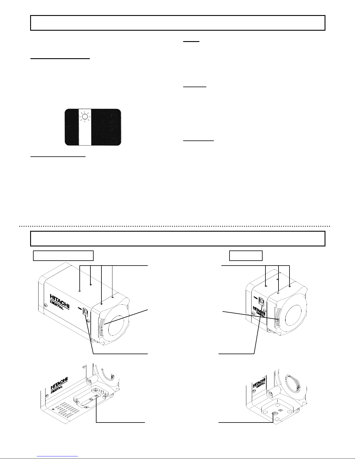
Tripode adaptor installation
screw hole
Refer to page 13 (Camera
installation).
LENS connector [LENS]
Connect the lens cable, when
using auto iris lens. Refer to
page 10 (Lens connectors).
Flange back adjustment dial
Adjust the flange back
Refer to page 11 (Flange
back adjustment)
Camera installation screw
KP-D5000/KP-D5001
KP-D5010
Page 6
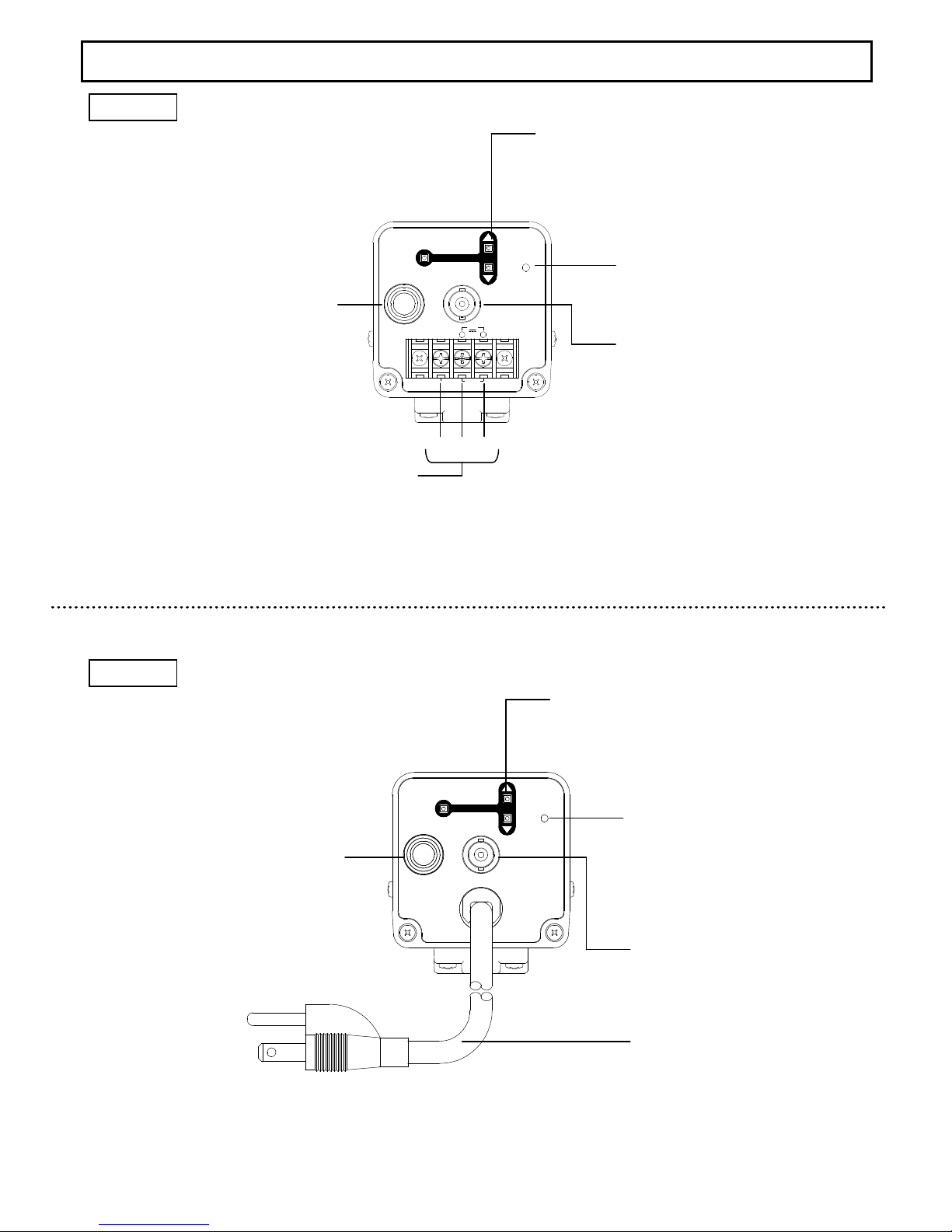
VIDEO
U
D
REMOTE
SET
STATUS
REMOTE connector [REMOTE]
Used to remote control the
camera setting
Refer to page 42 (Remote
operation of setting menu).
Power supply input terminal
Refer to page 8 (Power supply connection).
Camera menu setting operation switch [SETUP]
Various setting and adjustment values are
confirmed and changed with these 3 switches.
Refer to page 15 (Setting menu operations).
Status lamp
・Normal startup status:Green
・External synchronous mode:Orange
5
6
VIDEO
U
D
REMOTE
SET
-
AC
~
24V
12V
+
GND
DC
STATUS
Name and function of each section
KP-D5000
KP-D5001
AC power cable
Video output connector [VIDEO]
Refer to page 8 (Video output
connection).
②②②②
③③③③
①①①①
REMOTE connector [REMOTE]
Used to remote control the camera
setting
Refer to page 42(Remote operation
of setting menu).
Camera menu setting operation switch [SETUP]
Various setting and adjustment values are
confirmed and changed with these 3 switches.
Refer to page 15 (Setting menu operations).
Status lamp
・Normal startup status:Green
・External synchronous mode:Orange
Video output connector [VIDEO]
Refer to page 8 (Video output
connection).
Page 7
7
Connections
Vide
o output connection
Video output is connected from the camera back panel to the
video imput of the monitor via coaxial cable. If two or more
monitors are connected in a loop, set the 75Ω switch of only
the final monitor to ON.
The type of coaxial cable (75Ω) is decided according to the
distance with the connected device. The standard maximum
cable lengths without any unmarkable deterioration of image
are as follows.
3C-2V ・・・・ 150m
5C-2V ・・・・ 200m
7C-2V ・・・・ 300m
10C-2V ・・・・ 400m
Set the 75Ω switch of only the final monitor to on.
75Ω coaxial
cable
75Ω coaxial
cable
75Ω coaxial
cable
Color monitor
Color monitor
No.2
Color monitor
No.3
Power cable connection
Any special power supply is not required. Be sure to use the
power source specified in the specification.
(Please use the power supply of current capacity of 1A or
more, though it depends on the connected devices.)
Morever, please note that there is polarity in the 12V DC
power supply.
KP-D5000
Power supply input ratings
AC24V
AC24VAC24V
AC24V
DC12V
DC12VDC12V
DC12V
①①①①
1-L
○+
②②②②
2-N
○- (GND)
③③③③
GND Not used
Power supply input specification
VIDEO
U
D
REMOTE
SET
STATUS
12V
DC
PLATE RATED
SER.NO.
②②②②
①①①①
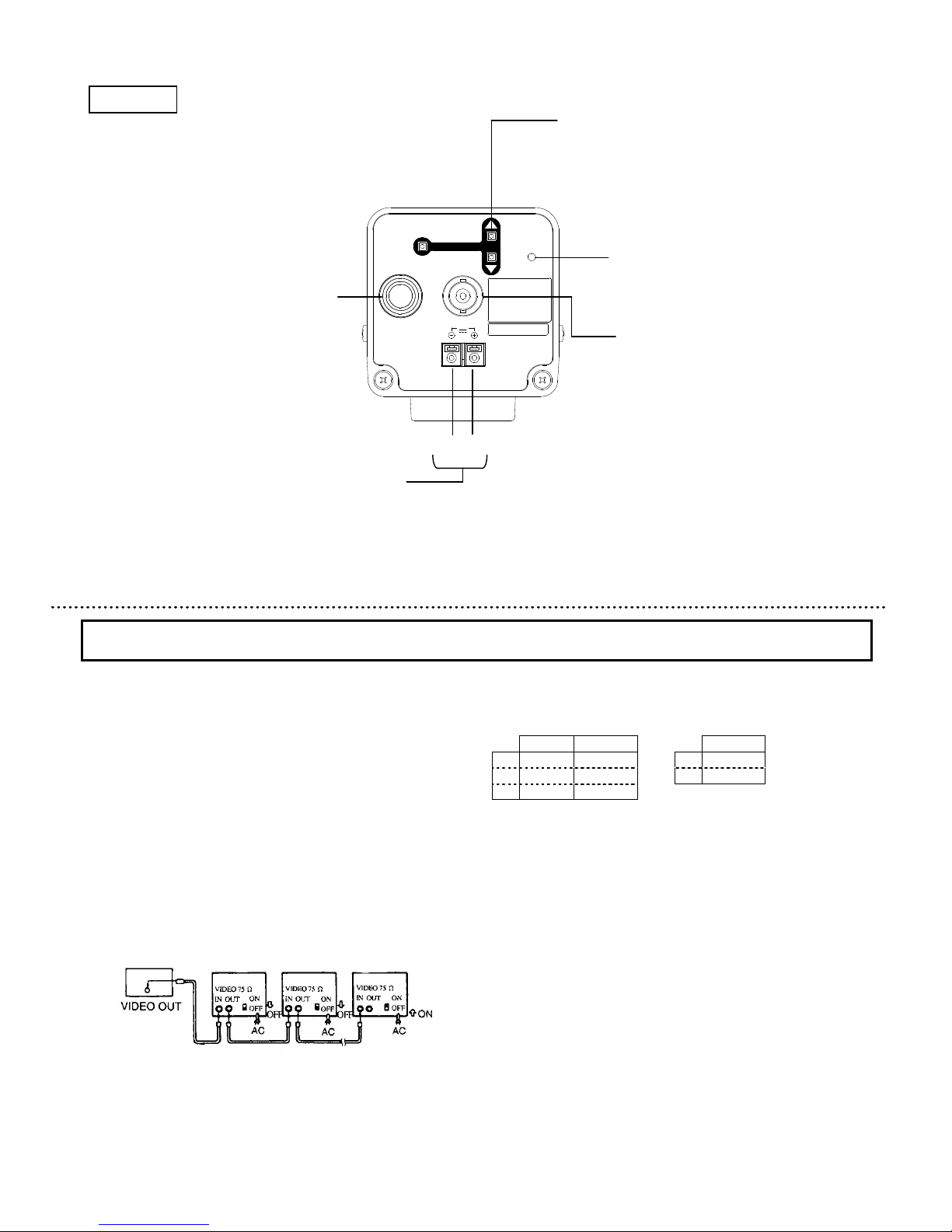
KP-D5010
Camera menu setting operation switch [SETUP]
Various setting and adjustment values are
confirmed and changed with these 3 switches.
Refer to page 15 (Setting menu operations).
Status lamp
・Normal startup status:Green
・External synchronous mode:Orange
Video output connector [VIDEO]
Refer to page 8 (Video output
connection).
REMOTE connector [REMOTE]
Used to remote control the camera
setting
Refer to page 42(Remote operation
of setting menu).
Power supply input terminal
Refer to page 8 (Power supply connection).
8
KP-D5010
Power supply input ratings
DC12V
DC12VDC12V
DC12V
①①①①
○+
②②②②
○- (GND)
Power supply input specification
:16~28AWG :16~28AWG
KP-D5000 / KP-D5001
/ KP-D5010
Page 8
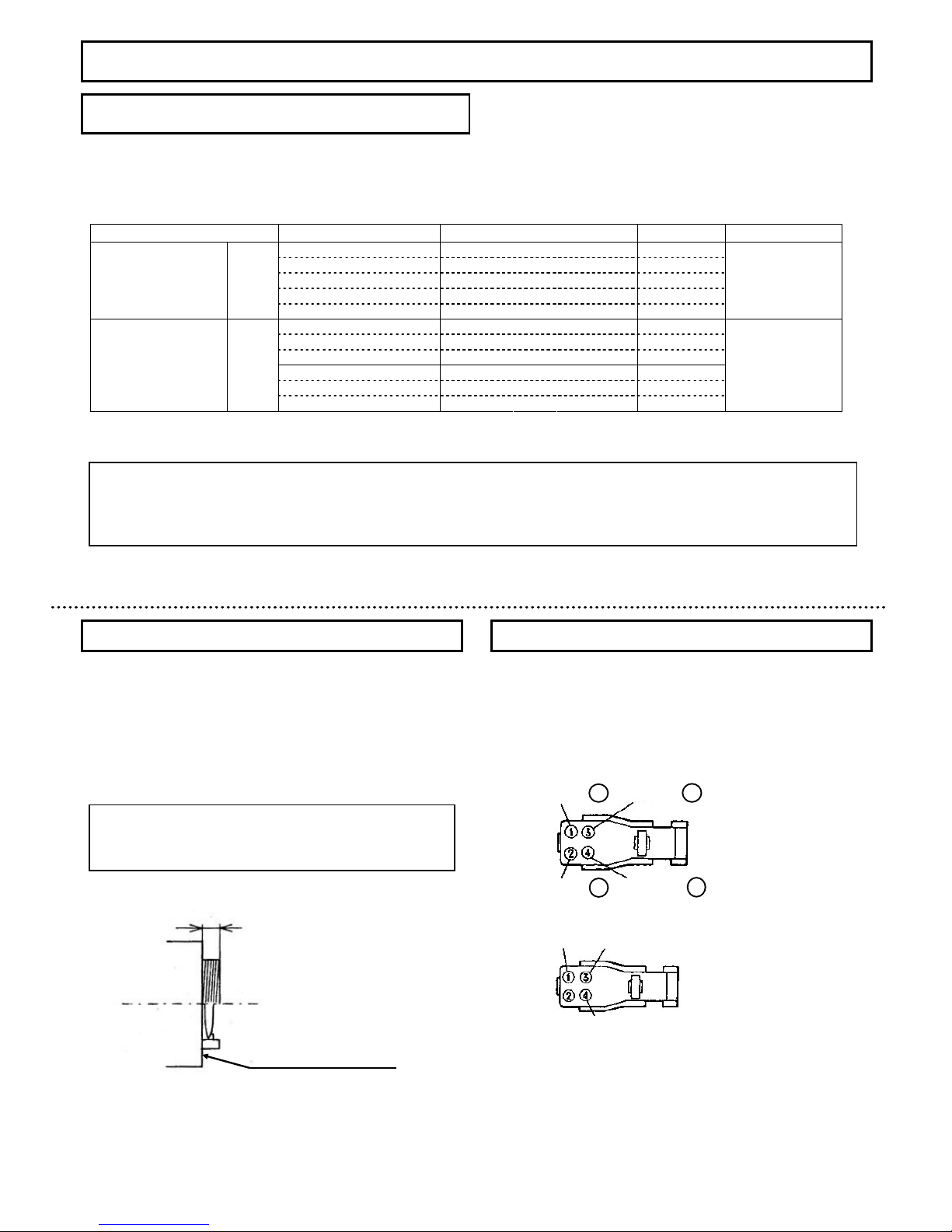
The plug pin arrangement should be according to the JEITC (Japan Electronics and Information Technology Industries Association)
specification for auto iris lens.
Please select the lens from the following list of recommended lens according to the using conditions.
Category Lens type name Specification Mount Lens SW
HS 3 16 E( F Q) 3.7 mm F1.6~300 CS-mount
HS 6 14 E( F Q) 6 mm F1.4~300 CS-mount
HS 1 21 4E (F Q) 12 mm F1.4~300 CS-mount
HS 2 V6 16 ED ※ 6~12 mm F1.6~300 CS-mount
Auto iris 1/2
HG 3 Z45 1 2F CS -IR
※
4.5~12.5 mm F1.2~360 CS-mount
DC
HS 3 16 E( F N) 3.7 mm F1.6~300 CS-mount
HS 6 14 E( F N) 6 mm F1.4~300 CS-mount
HS 1 21 4E (F N) 12 mm F1.4~300 CS-mount
H4 1 6E 4.2 mm F1.6~360 C-mount
H6 1 2E 6 mm F1.2~360 C-mount
Auto iris
( with iris amp )
1/2
H1 2 12 E 12 mm
F1.2~360 C-mount
VIDEO
※ RBSS compatible lens
Note
If another type of lens is used, it may create inconvenience in attaching the lens and the original camera performance may not
be obtained.
When purchasing, be sure to specify the JEITA compatible plug.
1) Dimension
A) of lens installation part should be according to
the figure below. When the lens with dimention more than the
following size is installed, the int
ernal damage of camera may
occur.
2)
Please do not install a lens which is heavier than the camera
body. In case of using such lens, please fix the lens to the
installation stand.
Lens selection
Caution
Use of heavy lens may damage the camera because of
unbalance.
C mount lens:less than 4.1mm
CS mount lens:less than 4.1mm
A
Lens
Flange surface of lens
When auto iris lens is used, lens cable is installed in the lens
plug as follows.
Please refer the manual for signal and color combination of
camera cable.
DC(Direct current)control voltage input type lens
Video signal input type lens
Install the head of lens cable to plug and then insert the plug in
the lens connector [LENS] of camera.
Lens connectors
+12V
Video input
GND
Damping coil -
Damping coil + Driving coil -
Driving coil +
9
10
Lens
Recommended lens
RBSS : Recognition of Better Security System by JAPAN SECURITY SYSTEMS ASSOCIATION
Page 9
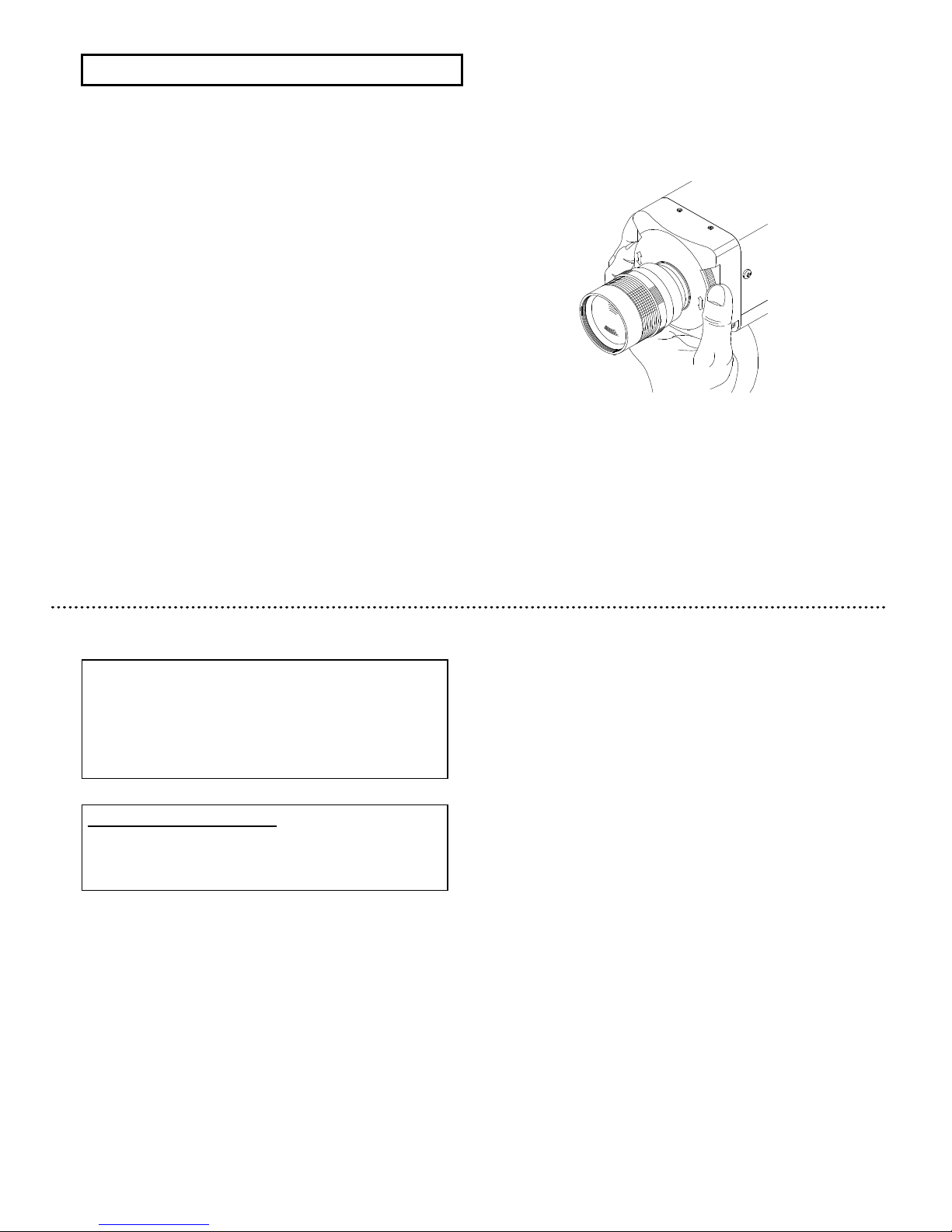
Flange
back adjustment is needed after installation of lens or in
cases where focus cannot be obtained by normal lens focus
operation and focus is lost at the wide ang
le settings of a zoom
lens.
In such cases, open the lens iris (refer to page 39)
and adjust as
follows.
1) Fixed focus lens
① Set the lens focus ring to infinity
② Aim towards an object at least 20 meters distant.
③ Turn the flange back adjustment dial to adjust the focus.
Please take care not to disturb the lens focus ring.
2) Zoom lens
① Aim towards an object at least 20 meters distant.
② Focus is adjusted by turning the focus ring. Loose
the lens mount screws. Set the lens to wide angle and
turn the flange
back adjustment dial to adjust the focus.
Please take care not to disturb the lens focus ring.
③ Again set to telephoto and adjust the focus by
turning the flange back adjustment dial.
④ Repeat these steps until the focus is not suitable
for telephoto and wide angle.
⑤ Finally, tighten the lens mount screws.
Flange back adjustment
11
※ The flange back adjustment can adjust C~CS mount range.
※ The angle of view is adjusted by turning the lens zoom ring.
Note
If an auto iris lens is used and the object distance is less
than few meters, due to focus length of lens, slight blurring
can occur at certain iris positions.
In such case, please refer to page 39[Lens open setting]
and set the lens to full open. At this time, AES is operated.
Auto Electric Shutter (AES)
AES is a function to automatically adjust the electronic
shutter speed according to the amount of incident light
and keeps the image level constant.
12
Page 10
The camera setting and adjustments can be changed to meet the using conditions. Use the setting menu displayed on the monitor
screen to check and change the settings and adjustments. The setting menu is comprised as follows.
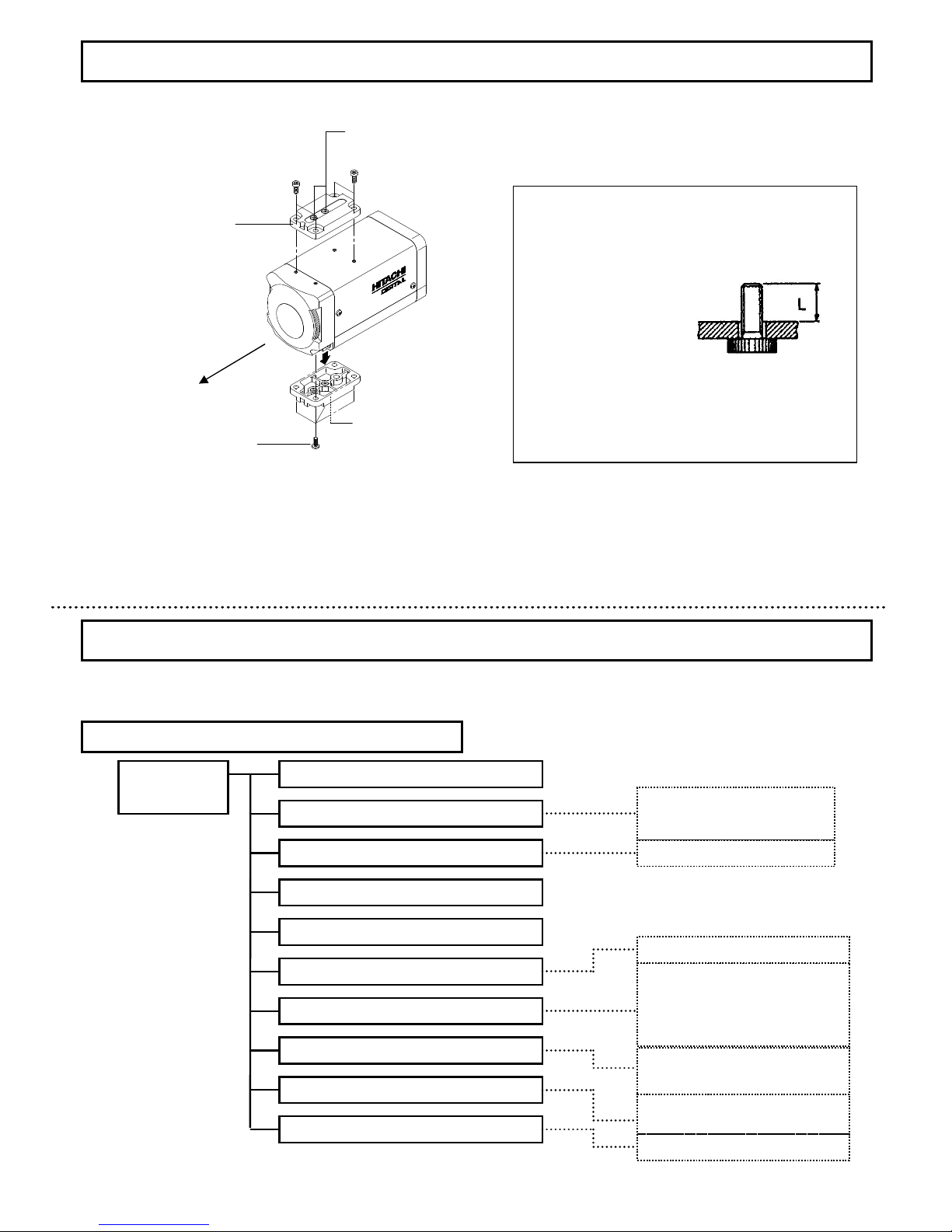
If the camera is to be suspended to the ceiling, change the position of the tripod adaptor from the bottom to the top of the camera, as
indicated in the figure.
Caution
Use the following type of camera mounting screw.
Type :U 1/4-20
Length:L=7mm
If length of screw is longer than 7 mm, there is risk of
internal damage to the camera. Conversely, if too short,
the camera will not be firmly secured and there is risk of
dropping.
Tripod adaptor
Binding head screws M3 x 8
13
14
Sett
ing menu composition
・Display character setting
・
Display position setting
White balance mode setting
・Auto tracking white balance (ATW)
・Preset white balance (AWC)
・Manual white balance (MANUAL)
・R/B gain adjustment etc
Color level adjustment, detail, black
level and digital zoom setting etc
Sub menu (page 38)
・BLC on/off and area setting
・Video level adjustment
AGC setting (page 22)
Shutter speed setting
(page 23)
Sensitivity enhancement setting (page 24)
Co
lor-B/W selection
(page 26)
・
AGC mode setting
Enhancement menu (page 33)
White balance setting (page 28)
・Burst setting
・Lens setting etc
Scene file setting (page 17)
Light control menu
(page 18)
Camera title setting (page 31)
Main menu
(page 16)
Camera mounting
Setting menu description
Lifting lug installation hole
Tripod installation hole
Camera angle
Page 11
16
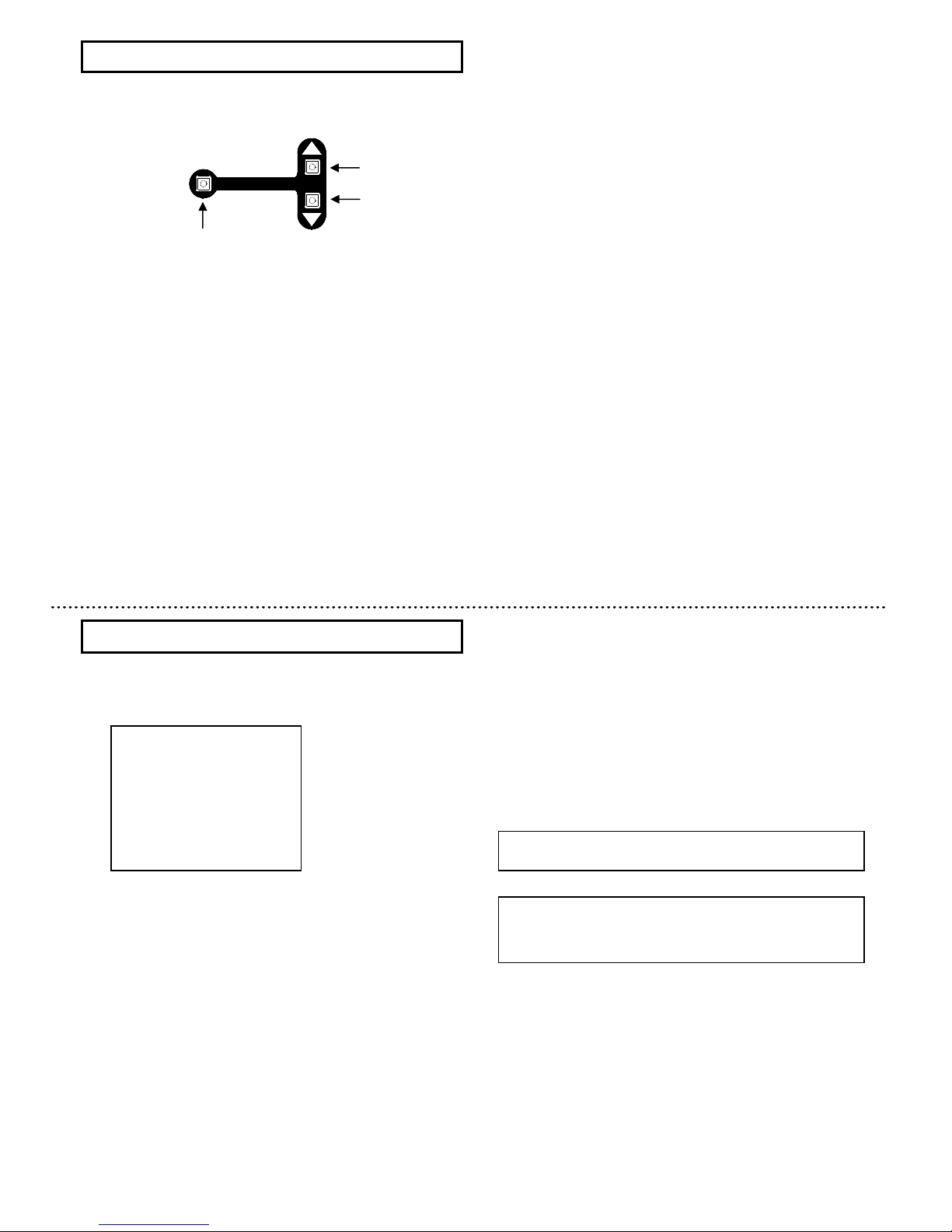
Three rear panel setup buttons are used to shift the cursor and
select items from the menus.
①
Up button:
Shift the cursor in the upward direction or increase an
adjustment value
②
Down button:
Shift the cursor in the downward direction or decrease an
adjustment value
③
Set button:
Press to display the main menu or to change a setting
Note
If any button is not pressed, the menu display disapears
automatically after about 5 minutes.
15
Setting menu operations
U
D
SET
①
②
③
Main menu
1) Press the Set button for at least 2 seconds to display
the Main
menu on the monitor screen.
2) Check the current settings at the main menu.
3) Shift the cursor vertically by pushing the Up and Down
buttons, then press the Set button to change the setting of
the selected item.
4) To return to the normal screen, shift the cursor to END
and
press the Set button.
5) Changed settings are stored in the camera memory
(EEPROM) and restored at the power on.
Main menu
>>>>
◆◆◆◆
MAIN
MAINMAIN
MAIN MENU
MENUMENU
MENU
◆◆◆◆(FILE1)
(FILE1)(FILE1)
(FILE1)
LIGHT
LIGHTLIGHT
LIGHT CONTROL:
CONTROL:CONTROL:
CONTROL:AVE
AVEAVE
AVE
↵↵↵↵
AGC
AGCAGC
AGC
:ON
:ON:ON
:ON
↵↵↵↵
SHUTTER
SHUTTERSHUTTER
SHUTTER SPEED:
SPEED:SPEED:
SPEED:1111////60
6060
60
SENS
SENSSENS
SENS UP
UPUP
UP
:OFF
:OFF:OFF
:OFF
B/W
B/WB/W
B/W MODE
MODEMODE
MODE
:OFF
:OFF:OFF
:OFF
↵↵↵↵
WHITE
WHITEWHITE
WHITE BALANCE:ATW
BALANCE:ATWBALANCE:ATW
BALANCE:ATW
↵↵↵↵
CAMERA
CAMERACAMERA
CAMERA TITLE
TITLETITLE
TITLE :OFF
:OFF:OFF
:OFF
↵↵↵↵
ENHANCE
ENHANCEENHANCE
ENHANCE ↵↵↵↵
SUB
SUBSUB
SUB MENU
MENUMENU
MENU
↵↵↵↵
END
ENDEND
END
……Scene file setting
……Light control menu
……AGC setting menu
……Shutter speed setting
……Sensitivity enhancement Setting
……Color-B/W mode setting
……White balance setting
……Camera title menu
……Enhance setting menu
……Sub menu
……End (Menu display off)
When an item indicated by a ↵ mark is selected, pressing
the Set button shifts to the next menu.
Page 12
17
Scene file setting
Light control mode setting
1) Press the Set button for longer than 2 seconds to
display the Main menu.
2) Use the Up and Down buttons to move the cursor to
LIGHT CONTROL. [AVE]/[BLC]/[PK/AVE] flashes.
3) In this state, push the Set button to display LIGHT
CONTROL MENU.
4) When the cursor is at MODE, push the Set button to change
control modes.
Set button::::AVERAGE→BLC→PEAK/AVE
AVE (Average mode)
This mode measures the average luminance of the entire
screen and controls the exposure level. This is default mode.
BLC (Back Light Control mode)
This mode controls the exposure level at the luminance level
of the specified area. (It can be selected from 9 areas).
PK/AVE (Peak/Average mode)
This mode uses the peak luminance together with average
and controls the exposure level. (The ratio of peak level and
average level can be changed.)
Light control menu
◆◆◆◆
LIGHT
LIGHTLIGHT
LIGHT CONTROL
CONTROLCONTROL
CONTROL MENU
MENUMENU
MENU
◆◆◆◆
>>>>
MODE
MODEMODE
MODE
:AVERAGE
:AVERAGE:AVERAGE
:AVERAGE
LEVEL
LEVELLEVEL
LEVEL
:::: 000
000000
000
AIE
AIEAIE
AIE :
: :
: OOOOFF
FFFF
FF
↑↑↑↑
RET
RETRET
RET
END
ENDEND
END
……Light control mode display
……Video level adjustment(-128~000~+127)
……AIE mode
……Return to Main menu
……End (Menu display off)
Light control menu [AVERAGE]
adjusted values of the camera at file.
1)
Press the Set button for at least 2 seconds to display the
main menu on the monitor screen.
2) Use UP and Down buttons to move the cursor to
MAIN
MENU. The scene file setting data blinks. In this state, push
the Set button to change the scene file.
Set button::::FILE1→FILE2→FILE3
→FILE4→FILE5
Factory setting is FILE1.
Scene file factory setting
Note
In case of using a video signal type lens, follow the
manual to change setting of sensitivity of the lens.
Main menu
>>>>
◆◆◆◆
MAIN
MAINMAIN
MAIN MENU
MENUMENU
MENU
◆◆◆◆(FILE1)
(FILE1)(FILE1)
(FILE1)
LIGHT
LIGHTLIGHT
LIGHT CONTROL:
CONTROL:CONTROL:
CONTROL:AVE
AVEAVE
AVE
↵↵↵↵
AGC
AGCAGC
AGC
:ON
:ON:ON
:ON
↵↵↵↵
SHUTTER
SHUTTERSHUTTER
SHUTTER SPEED:
SPEED:SPEED:
SPEED:1111////60
6060
60
SENS
SENSSENS
SENS UP
UPUP
UP
:OFF
:OFF:OFF
:OFF
B/W
B/WB/W
B/W MODE
MODEMODE
MODE
:OFF
:OFF:OFF
:OFF
↵↵↵↵
WHITE
WHITEWHITE
WHITE BALANCE:ATW
BALANCE:ATWBALANCE:ATW
BALANCE:ATW
↵↵↵↵
CAMERA
CAMERACAMERA
CAMERA TITLE
TITLETITLE
TITLE :OFF
:OFF:OFF
:OFF
↵↵↵↵
ENHANCE
ENHANCEENHANCE
ENHANCE ↵↵↵↵
SUB
SUBSUB
SUB MENU
MENUMENU
MENU
↵↵↵↵
END
ENDEND
END
……Scene file setting
……Light control menu
……AGC setting menu
……Shutter speed setting
……Sensitivity enhancement Setting
……Color-B/W mode setting
……White balance setting
……Camera title menu
……Enhance setting menu
……Sub menu
……End (Menu display off)
Video level adjustment
The optimum video level is to factory setting(000).
If necessary, the level can be changed as foIIows.
1) Use the Up and Down buttons to shift the cursor to LEVEL
and press the Set button. The adjustment value at the right
of LEVEL flashes.
2) Change the video level by pressing the Up and Down
buttons.
Adjustment value range : -128~000~+127
For factory setting(000), hold down both the Up and Down
buttons simultaneously for 2 seconds.
When the cursor is blinking, pressing Set button will stop
blinking and setting value will be fixed. In this case, the
cursor moves to AIE.
18
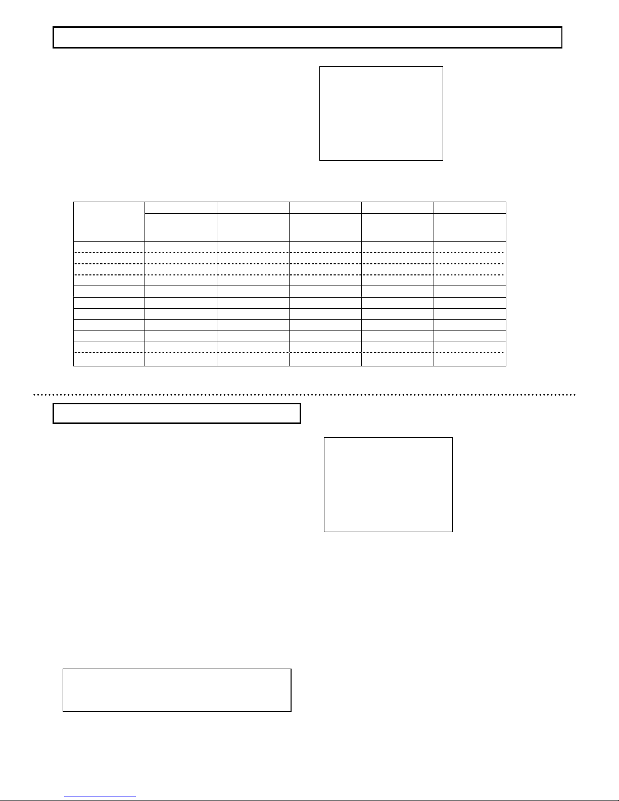
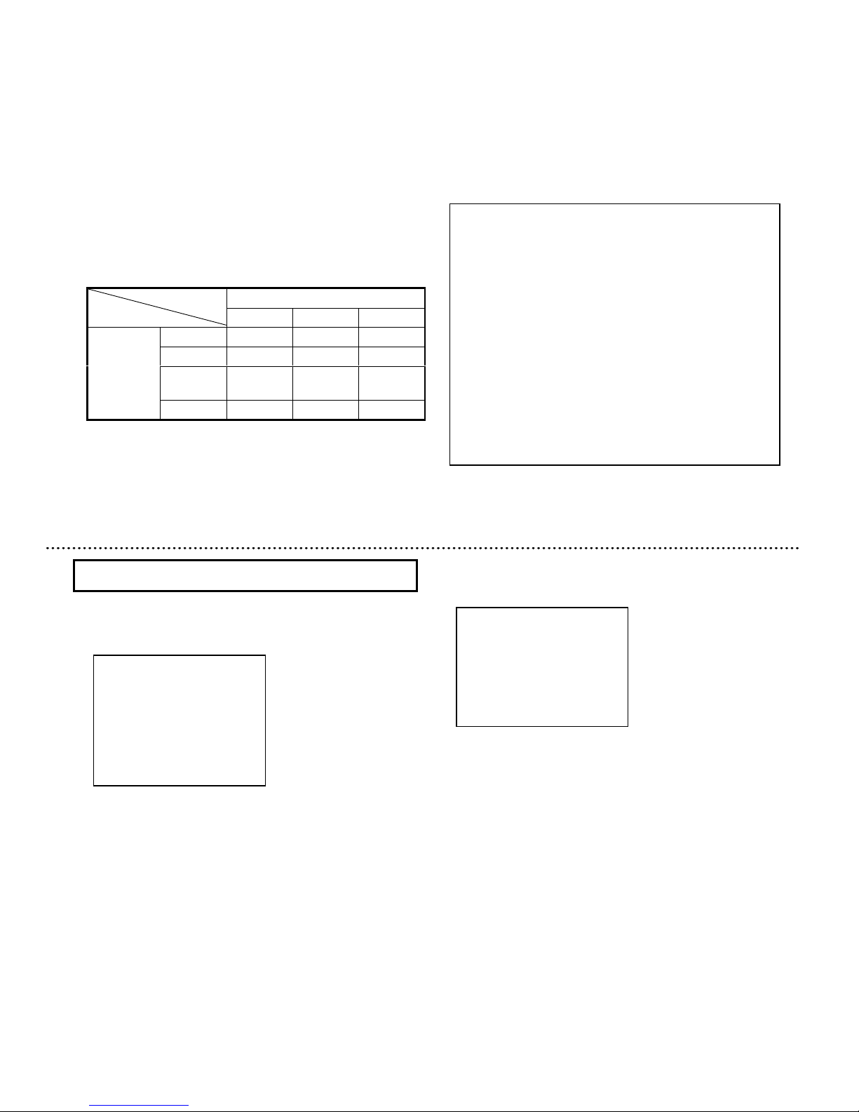
Scene file No.
1 2 3 4 5
High sensitivity
setting
Fog
adjustment(color)
setting
Fog
adjustment(B/W)
setting
Back light
correction setting
Stored high
sensitivity setting
LIGHT CONTROL
MODE AVERAGE AVERAGE AVERAGE BLC AVERAGE
AREA
--- --- ---
NO.1
---
AIE OFF OFF OFF MID OFF
AGC 51 31 31 31 51
DNR
HI HI HI HI HI
SHUTTER SPEED
1/60 1/60 1/60 1/60 1/60
SENS UP OFF OFF OFF OFF AUTOx16
B/W MODE OFF OFF ON OFF OFF
ENHANCE
FOG ADJUST OFF AUTO AUTO OFF OFF
*The other settings besides this table will be same as factory setting of file1.
Page 13
.
19
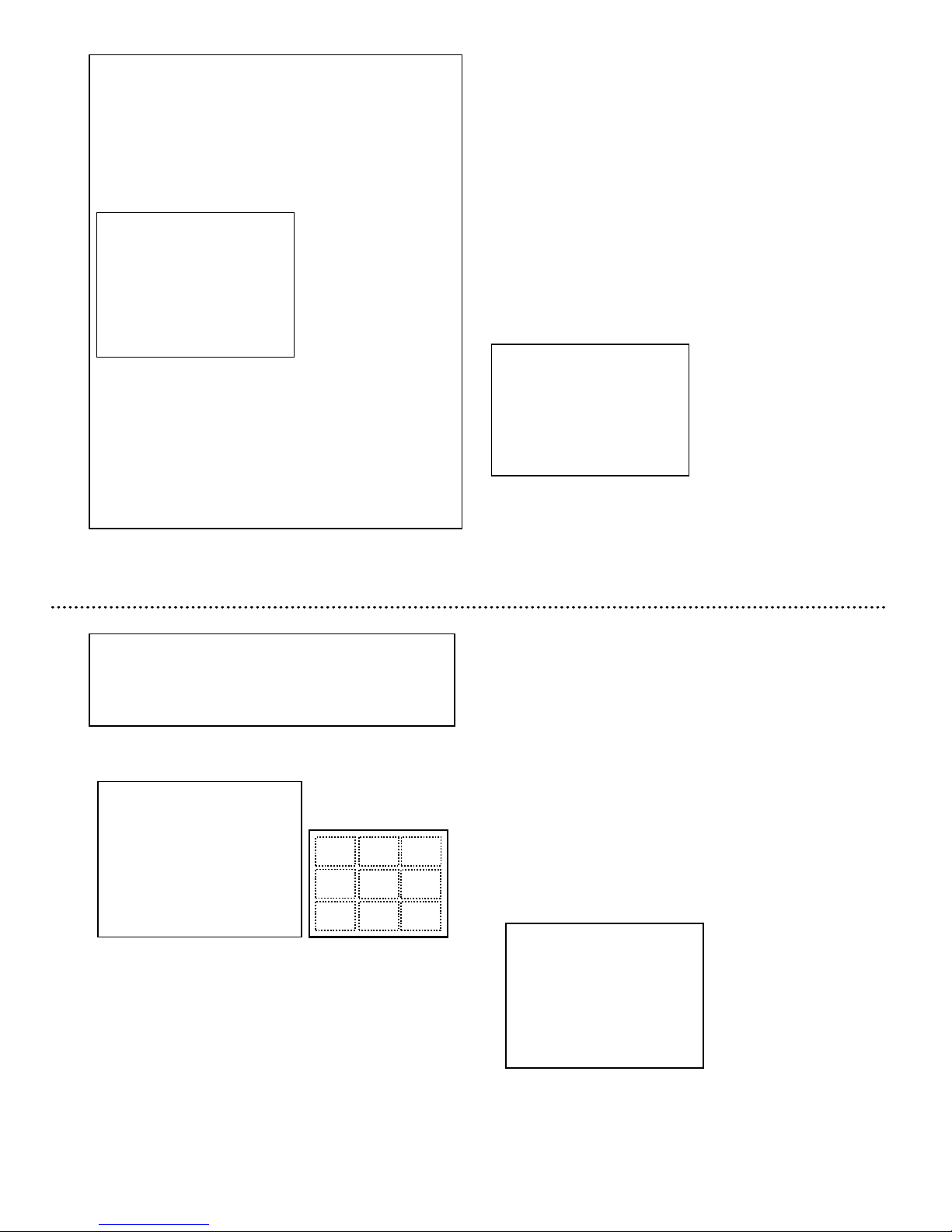
Back light control mode setting
The lens iris closes in response to brightness when strong
light or sun light is hitting the spot besides the place to be
observed, and the subject of interest becomes dark. This
mode is used to avoid darkening of subject of interest in such
condition.
1) Press the Set button for longer than 2 seconds to display
the Main menu.
2) Use the Up and Down buttons to move the cursor to
LIGHT CONTROL. [AVE]/[BLC]/[PK/AVE] flashes.
3) In this state, push the Set button to display LIGHT
CONTROL MENU.
4) When the cursor is at MODE, push the Set button and
select BLC. The following menu is displayed.
◆◆◆◆
LIGHT
LIGHTLIGHT
LIGHT CONTROL
CONTROLCONTROL
CONTROL MENU
MENUMENU
MENU
◆◆◆◆
>>>>
MODE
MODEMODE
MODE
:BLC
:BLC:BLC
:BLC
AREA
AREAAREA
AREA SELECT:NO.
SELECT:NO.SELECT:NO.
SELECT:NO.1111
↵↵↵↵
LEVEL
LEVELLEVEL
LEVEL
:::: 00
0000
000000
AIE
AIEAIE
AIE :
: :
: OOOOFF
FFFF
FF
↑↑↑↑
RET
RETRET
RET
END
ENDEND
END
……Light control mode display
……Photomatric Area select : No.1~9
……Video level adjustment(-128~000~+127)
……AIE mode
……Return to Main menu
……End(Menu display off)
Light control menu [BLC]
5) Move the cursor to AREA SELECT and push Set
button to
display the detection area select menu.
6) There are 9
light detection areas that can be selected by the
Up and Down buttons. Select the areas from No. 1 to 9 such
that subject of interest enters in the selected area.
It is set to No.1 in factory setting.
Up button : 1→2→3→4→5→6→7→8→9
(ascending order)
Down button: 9→8→7→6→5→4→3→2→1
(descending order)
7)
After deciding the detection area, press the Set button to
return to the LIGHT CONTROL MENU.
AREA(BLC)
AREA(BLC)AREA(BLC)
AREA(BLC)
NO.
NO.NO.
NO.1111
┏━━━━━━┓
┏━━━━━━┓┏━━━━━━┓
┏━━━━━━┓
┃┃┃┃
┃┃┃┃
┃┃┃┃
┃┃┃┃
┗━━━━━━┛
┗━━━━━━┛┗━━━━━━┛
┗━━━━━━┛
Detection area setting menu
Area position and number
6666 5555
4444
2222
1111 3333
7777
8888 9999
Peak/Average mode setting
When there is strong light spot within the
image, the near by
area of spot may have overexposure and the subject might not
be confirmed. This mode is used when taking picture under
such condition. It can control overexposure in such conditions.
1) Press the Set button for longer than 2 seconds to
display the Main menu.
2) Use the Up and Down buttons to move the cursor to
LIGHT CONTROL. [AVE]/[BLC]/[PK/AVE] flashes.
3) In this state, push the Set button to display LIGHT
CONTROL MENU.
4) When the cursor is at MODE, push the Set button
and select PEAK/AVE. The following menu is displayed.
Note
1) The backlighting compensation of a central emphasis is
set at the time of electronic zoom operation.
2) The back light control mode does not operate in case of
using video signal input type auto iris lens.
Note
In case of using video signal input type auto iris lens
1) Lens iris operates by the sensitivity setting of lens
regardless light control mode setting.
2) When the LENS TYPE setting of the camera is
set to VIDEO, the lens sensitivity setting adjustment
gauge (Lev/Ref) is displayed on LIGHT CONTROL
MENU.
。
3) Set the sensitivity on the lens such that the Video
output level setting [Lev] should not fall less than the
standard level of the exposure control [Ref].
4) If it is adjusted lower than the value of [Ref], the
repetition phenomenon of the lens iris control and the
AGC control (Hunting) might be generated.
◆◆◆◆
LIGHT
LIGHTLIGHT
LIGHT CONTROL
CONTROLCONTROL
CONTROL MENU
MENUMENU
MENU
◆◆◆◆
>>>>
MODE
MODEMODE
MODE
:AVERAGE
:AVERAGE:AVERAGE
:AVERAGE
Lev
LevLev
Lev |||||||||||||||||||||||||||||||||||||||||||||||・・・・・・・・・・・・・・・・・・・・・・・
・・・・・・・・・・・・・・・・・・・・・・・・・・・・・・・・・・・・・・・・・・・・・・
・・・・・・・・・・・・・・・・・・・・・・・
Ref
RefRef
Ref ||||||||||||||||||||||||||||||||||||||||||||||・・・・・・・・・・・・・・・・・・・・・・・
・・・・・・・・・・・・・・・・・・・・・・・・・・・・・・・・・・・・・・・・・・・・・・
・・・・・・・・・・・・・・・・・・・・・・・
LEVEL
LEVELLEVEL
LEVEL
:::: 000
000000
000
AIE
AIEAIE
AIE
:OF
:OF:OF
:OFFFFF
RET
RETRET
RET
END
ENDEND
END
……Light control mode display
……Video output level gauge
……Light control standard level gauge
……Video level adjustment(-128~000~+127)
……AIE mode
……Return to Main menu
……End (Menu display off)
Light control menu [AVERAGE]
◆◆◆◆
LIGHT
LIGHTLIGHT
LIGHT CONTROL
CONTROLCONTROL
CONTROL MENU
MENUMENU
MENU
◆◆◆◆
MODE
MODEMODE
MODE
:PEAK/AVE
:PEAK/AVE:PEAK/AVE
:PEAK/AVE
>>>>
PK/AV
PK/AVPK/AV
PK/AV
:::: 15
1515
15//// 85
8585
85
LEVEL
LEVELLEVEL
LEVEL
:::: 000
000000
000
AIE
AIEAIE
AIE :
: :
: OOOOFF
FFFF
FF
↑↑↑↑
RET
RETRET
RET
END
ENDEND
END
……Light control mode display
……Peak level/Average
……Video level adjustment(-128~000~+127)
……AIE mode
……Return to Main menu
……End (Menu display off)
Light control menu [PEAK/AVE]
20
Page 14
21
AGC setting
AGC
mode setting
1) Press the Set button for longer than 2 se
conds to display the
Main menu.
2) Use the Up and Down buttons to move the cursor to
AGC.
AGC setting data blinks.
3) In this state, push the Set button to display AGC MENU.
4) When the cursor is at MODE, push the Set button
to change
the AGC modes as follows.
Set button : ON→OFF
ON : Automatically changes the video level within
a range of the AGC limit as appropriate according to
the brightness of subject. AGC is set to ON in
factory setting.
OFF : Always sets a fixed video level from the [FIX. GAIN].
◆◆◆◆
AGC
AGCAGC
AGC MENU
MENUMENU
MENU
◆◆◆◆
>>>>
MODE
MODEMODE
MODE
:ON
:ON:ON
:ON
AGC
AGCAGC
AGC LIMIT
LIMITLIMIT
LIMIT
:+
:+:+
:+31
3131
31
0000・・・・・・・・
・・・・・・・・・・・・・・・・
・・・・・・・・●●●●・・・・・・
・・・・・・・・・・・・
・・・・・・51
5151
51
DNR
DNRDNR
DNR
::::OFF
OFFOFF
OFF
RET
RETRET
RET
END
ENDEND
END
……AGC mode display
……AGC lmit (0~+51)
……AGC limit gauge
……Digital Noise Reduction(DNR)display
……Return to Main menu
……End (Menu display off)
AGC setting menu (ON)
メイン設定メニュー
<<<
MAIN MENU
>>>
TITLE :OFF
↵
LIGHT CONTROL:OFF ↵
>
AGC :ON(31dB)
SHUTTER SPEED:OFF
SENS UP :OFF
B/W MODE :AUTO(MID)
WHITE BALANCE:ATW ↵
DIGITAL ZOOM :OFF
↵
SUB MENU
↵
END
AGC limit setting (AGC ON)
1) When the cursor is at AGC LIMIT, push the Set button.
A mark[●] at the AGC limit gauge flashes.
2) In this state, use the Up and Down buttons to change
the AGC limit.( 0~+51). For factory setting by the Scene file
(page 17), hold down both the Up and Down buttons
simultaneously for 2 seconds.
3) In this state, pressing Set button will stop blinking and setting
value will be fixed. The the cursor moves to RET.
AGC limit setting (AGC OFF)
1) When the cursor is at FIX GAIN, push the Set button.
A mark[●] at the FIX GAIN gauge flashes.
◆◆◆◆
AGC
AGCAGC
AGC MENU
MENUMENU
MENU
◆◆◆◆
>>>>
MODE
MODEMODE
MODE
:O
:O:O
:OFF
FFFF
FF
FIX
FIXFIX
FIX GAIN
GAINGAIN
GAIN
:+
:+:+
:+31
3131
31
----6666・・・・・・・・
・・・・・・・・・・・・・・・・
・・・・・・・・●●●●・・・・・・
・・・・・・・・・・・・
・・・・・・51
5151
51
DNR
DNRDNR
DNR
::::OFF
OFFOFF
OFF
RET
RETRET
RET
EEEEND
NDND
ND
……AGC mode display
……AGC lmit (-6~+51)
……AGC limit gauge
……Digital Noise Reduction(DNR)display
……Return to Main menu
……End (Menu display off)
AGC setting menu (OFF)
22
AIE mode
AIE is a function to correct brightness of the part that has
darkened as a result of over exposure control by BLC and
PEAK/AVE.
When the cursor is at AIE, push the Set button to change the
AIE modes as follows.
Set button : OFF→LOW→MID→HIGH
OFF : AIE is inactive.
It is set for AIE in factory setting.
LOW, MID, HIGH : AIE is effective.
The enhancement level of the part that
has darkened is changed to
LOW, MID, HIGH.
5) Move the cursor to PK/AV and push Set button to
display the ratio of peak and average.
Set button : 0/100→ 15/ 85→ 30/ 70→ 50/ 50
→ 75/ 25→ 100/0
The response to spot light increases with increment
in peak value. Factory setting is 15/85.
Note
The part that has darkened is corrected brightness by
the enhancement level increment, but the picture might
be noisy. Therefore, set the enhance level with taking
picture conditions.
Page 15
23
2) In this state, use the Up and Down buttons to change
the FIX GAIN ( -6~+51).
For factory setting(+0), hold down
both the Up and Down buttons simultaneously for 2 seconds.
3) In this state, pressing Set button will stop blinking and
setting value will be fixed. The the cursor moves to RET.
Digital Noise Reduction((((DNR))))setting
It is a function to reduce the noise element generated
by AGC
gain increment. Use the Up and Down buttons to move the cu
rsor
to DNR
and push the Set button to change the DNR modes as
follows.
Set button::::OFF→HIGH→LOW
OFF : DNR is inactive.
HIGH : Image quality priority mode
LOW : Movement priority mode
DNR is set to HIGH in factory setting.
Note
At high AGC LIMIT/FIX. GAIN, sensitivity increases,
but noise becomes more apparent.
Note
1) When using a DC type/VIDEO type auto iris lens, fix
the iris to fully open.
2) When the following phenomenon occurs while
AES is operating, change to different shutter speed.
The following are not defects.
Strong smear or blooming occurs in the scene.
Screen flicker or coloration occurs.
SENS UP is
a sensitivity enhancement function that increases the
CCD exposure time (shutter speed) greater than 1/60 or 1/50
seconds of the standard time.
1) Press the Set button for longer than 2 seconds to display
the Main menu.
2) Use the Up and Down buttons to move the cursor
to SENS UP. Sensitivity enhancement setting data flashes.
3) In this state, push the Set button to change the sensitivity
enhancement setting as follows.
Set button :
OFF→AUTOx2→AUTOx4→AUTOx6→AUTOx8
→AUTOx10→AUTOx12→AUTOx16→AUTOx32
→AUTOx64→AUTOx128→OFF→MANU x2
→MANUx4→MANUx6→MANx8→MANUx10
→MANUx12→MANUx16→MANUx32→MANUx64
→MANUx128→MANUx192→MANUx256
→MANUx320→MANUx384→MANUx448→MANUx512
Sensitivity enhancement setting (SENS UP))))
24
1) Press the Set button for longer than 2 seconds to
display the Main menu.
2) Use the Up and Down buttons to move the cursor
to SHUTTER SPEED. Shutter speed setting data flashes.
In this state, push the Set button to change the shutter
speed as follows.
Set button : 1/60(1/50 PAL)→1/100(1/120 PAL)
→1/250→1/500→1/1000→1/2000→1/5000
→1/10000→1/20000→1/50000
→1/100000→AES→AES&LENS(1/1000)
→AES&LENS(1/2000)
→AES&LENS(1/5000)
Factory setting : 1/60 (1/50)
Shutter speed setting
Main menu
◆◆◆◆
MAIN
MAINMAIN
MAIN MENU
MENUMENU
MENU
◆◆◆◆(FILE1)
(FILE1)(FILE1)
(FILE1)
LIGHT
LIGHTLIGHT
LIGHT CONTR
CONTRCONTR
CONTROL:
OL:OL:
OL:AVE
AVEAVE
AVE
↵↵↵↵
AGC
AGCAGC
AGC
:ON
:ON:ON
:ON
↵↵↵↵
>>>>
SHUTTER
SHUTTERSHUTTER
SHUTTER SPEED:
SPEED:SPEED:
SPEED:1111////60
6060
60
SENS
SENSSENS
SENS UP
UPUP
UP
:OFF
:OFF:OFF
:OFF
B/W
B/WB/W
B/W MODE
MODEMODE
MODE
:OFF
:OFF:OFF
:OFF
↵↵↵↵
WHITE
WHITEWHITE
WHITE BALANCE:ATW
BALANCE:ATWBALANCE:ATW
BALANCE:ATW
↵↵↵↵
CAMERA
CAMERACAMERA
CAMERA TITLE
TITLETITLE
TITLE :OFF
:OFF:OFF
:OFF
↵↵↵↵
ENHANCE
ENHANCEENHANCE
ENHANCE
↵↵↵↵
SUB
SUBSUB
SUB MENU
MENUMENU
MENU
↵↵↵↵
END
ENDEND
END
……Scene file setting
……Light control menu
……AGC setting menu
……Shutter speed setting
……Sensitivity enhancement Setting
……Color-B/W mode setting
……White balance setting
……Camera title menu
……Enhance setting menu
……Sub menu
……End (Menu display off)
Note
When DNR is effective, the after image might be
occurred, in case of taking picture of fast moving object.
Main menu
◆◆◆◆
MAIN
MAINMAIN
MAIN MENU
MENUMENU
MENU
◆◆◆◆(FILE1)
(FILE1)(FILE1)
(FILE1)
LIGHT
LIGHTLIGHT
LIGHT CONTROL:
CONTROL:CONTROL:
CONTROL:AVE
AVEAVE
AVE
↵↵↵↵
AGC
AGCAGC
AGC
:ON
:ON:ON
:ON
↵↵↵↵
SHUTTER
SHUTTERSHUTTER
SHUTTER SPEED:
SPEED:SPEED:
SPEED:1111////60
6060
60
>>>>
SENS
SENSSENS
SENS UP
UPUP
UP
:OFF
:OFF:OFF
:OFF
B/W
B/WB/W
B/W MODE
MODEMODE
MODE
:OFF
:OFF:OFF
:OFF
↵↵↵↵
WHITE
WHITEWHITE
WHITE BALANCE:ATW
BALANCE:ATWBALANCE:ATW
BALANCE:ATW
↵↵↵↵
CAMERA
CAMERACAMERA
CAMERA TITLE
TITLETITLE
TITLE :OFF
:OFF:OFF
:OFF
↵↵↵↵
ENHANCE
ENHANCEENHANCE
ENHANCE
↵↵↵↵
SUB
SUBSUB
SUB MENU
MENUMENU
MENU
↵↵↵↵
END
ENDEND
END
……Scene file setting
……Light control menu
……AGC setting menu
……Shutter speed setting
……Sensitivity enhancement Setting
……Color-B/W mode setting
……White balance setting
……Camera title menu
……Enhance setting menu
……Sub menu
……End (Menu display off)
Auto Electric Shutter (AES)
AES is a function to automatically adjust the electronic
shutter speed according to the amount of incident light
and keep the image level constant.
Page 16
25
26
Sensitivity enhancement by Color-B/W selection (B/W mode)
1) Press the Set button for longer than 2 seconds to
display the
Main menu.
上に表示させます。
2) Use the Up and Down buttons to move the cursor to
B/W MODE. B/W MODE setting data flashes.
3) In this state, push the Set button to display B/W
MODE MENU.
4) In this state, push the Set button to change the
color/BW
mode setting as follows.
Set button:::: OFF→ON→AUTO((((H))))→AUTO((((M))))
→AUTO((((L))))
Note
1) Sensitivity goes up when the sensitivity enhancement
is increased, but when taking picture of subject with a
fast movement, the blur of the image (after image)
grows too.
2) Sensitivity goes up when the sensitivity enhancement
is increased, but the noise of image is also increases.
Morever, if the surrounding temperature is high,
amount of the noise might increase.
3) White pixel might be there at the time of sensitivity
enhancement operation. This is not a defect.
4) Turn ON the DNR when the noise stands out with
sensitivity improvement. The afterimage might stand
out when taking picture of subject with a fast
movement. At that time, switch the DNR setting to
OFF.
Color-B/W selection (B/W mode)
OFF : Sensitivity enhancement function is not used.
It is factory setting.
AUTO : As the scene darks, this mode changes the sensitivity
enhancement automatically with in the range that is
set. In case of insufficient sensitivity with only AGC,
this mode is used for day and night continous
surveillance.
MANU : Mode for fixed sensitivity enhancement. It is fixed at
maximum gain, when AGC is ON.
Relation of SENS UP setting and SHUTTER SPEED
SENS UP
SENS UPSENS UP
SENS UP Setting
Setting Setting
Setting
OFF
OFFOFF
OFF AUTO
AUTOAUTO
AUTO MAN
MANMAN
MANUUUU
1/60
1/601/60
1/60 (1/50)
(1/50) (1/50)
(1/50)
1/60(1/50)
1/60(1/50)1/60(1/50)
1/60(1/50) 1/60(1/50)
1/60(1/50)1/60(1/50)
1/60(1/50) 1/60(1/50)
1/60(1/50)1/60(1/50)
1/60(1/50)
1/100
1/1001/100
1/100(1/120)
(1/120)(1/120)
(1/120)
1/100
1/1001/100
1/100(1/120)
(1/120)(1/120)
(1/120)
1/100(1/120)
1/100(1/120)1/100(1/120)
1/100(1/120)
1/
1/1/
1/60(1/50)
60(1/50)60(1/50)
60(1/50)
1/
1/1/
1/250
250250
250
||||
1/100000
1/1000001/100000
1/100000
1/
1/1/
1/250
250250
250
||||
1/100000
1/1000001/100000
1/100000
1/
1/1/
1/60(1/50)
60(1/50)60(1/50)
60(1/50) 1/
1/1/
1/60(1/50)
60(1/50)60(1/50)
60(1/50)
SHUTTER
SHUTTERSHUTTER
SHUTTER
SPEED
SPEEDSPEED
SPEED
AES
AESAES
AES AES
AESAES
AES AES
AESAES
AES 1/
1/1/
1/60(1/50)
60(1/50)60(1/50)
60(1/50)
OFF : This mode is of color picture. (factory setting)
ON : This mode is of black and white picture.
AUTO : In this mode, color image ⇔ black and white
image is changed automatically according to
the brightness of subject.
It is the brightness (picture level)
that displayed
inside ( )
when color image is changed to black and
white image.
AUTO(H):About 70% or less of proper value
AUTO(M):About 50% or less of proper value
AUTO(L) :About 35% or less of proper value
When switching from black and white picture to color picture,
AGC gain or SENS UP refers to magnification. Therefore,
when AGC setting is OFF and furthermore, SENS UP setting
is OFF/MANU, AUTO setting of BW MODE can not be used.
◆◆◆◆ B/W
B/WB/W
B/W MENU
MENU MENU
MENU ◆◆◆◆
>>>>
M OD E
M OD EM OD E
M OD E
::::O F F
O F FO F F
O F F
BURST
BURSTBURST
BURST
::::ON
ONON
ON
MONO
MONOMONO
MONO→→→→COLOR
COLORCOLOR
COLOR :::: 010
010 010
010
COLORR
COLORRCOLORR
COLORR→→→→MONO
MONO MONO
MONO :::: 005
005 005
005
RET
RETRET
RET
END
ENDEND
END
……B/W mode
……Burst setting
……
B/W to color mode change time sett ing
……
Color to B/W mode change time setti ng
……Return to Main menu
……End (Menu display off)
Main menu
◆◆◆◆
MAIN
MAINMAIN
MAIN MENU
MENUMENU
MENU
◆◆◆◆(FILE1)
(FILE1)(FILE1)
(FILE1)
LIGHT
LIGHTLIGHT
LIGHT CONTROL:
CONTROL:CONTROL:
CONTROL:AVE
AVEAVE
AVE
↵↵↵↵
AGC
AGCAGC
AGC
:ON
:ON:ON
:ON
↵↵↵↵
SHUTTER
SHUTTERSHUTTER
SHUTTER SPEED:
SPEED:SPEED:
SPEED:1111////60
6060
60
SENS
SENSSENS
SENS UP
UPUP
UP
:OFF
:OFF:OFF
:OFF
>>>>
B/W
B/WB/W
B/W MODE
MODEMODE
MODE
:OFF
:OFF:OFF
:OFF
↵↵↵↵
WHITE
WHITEWHITE
WHITE BALANCE:ATW
BALANCE:ATWBALANCE:ATW
BALANCE:ATW
↵↵↵↵
CAMERA
CAMERACAMERA
CAMERA TITLE
TITLETITLE
TITLE :OFF
:OFF:OFF
:OFF
↵↵↵↵
ENHANCE
ENHANCEENHANCE
ENHANCE
↵↵↵↵
SUB
SUBSUB
SUB MENU
MENUMENU
MENU
↵↵↵↵
END
ENDEND
END
……Scene file setting
……Light control menu
……AGC setting menu
……Shutter speed setting
……Sensitivity enhancement Setting
……Color-B/W mode setting
……White balance setting
……Camera title menu
……Enhance setting menu
……Sub menu
……End (Menu display off)
B/W setting menu
1) SHUTTER SPEED can not be changed
to be other than
1/60 or 1/100 when SENS UP is AUTO and MANU.
2) If SHUTTER SPEED setting is other than 1/60, 1/100
or
AES, it is changed to 1/60 when the SENS UP
setting is
changed to AUTO.
3) If SHUTTER SPEED setting is other than 1/60
, it is changed
to 1/60 when the SENS UP setting is changed to MANU.
Page 17
Color/BW switching
The camera CCD responds to infrared light(700 ~~~~
1000nm) that is invisible to the human eye. Normal color
camera uses an IR cut filter to remove the infrared
components in order to bring it close to human eye. This
condition is used for color image. In case of black and
white image, the IR cut filter is removed in order to making
it more sensitive for infrared light.
Note
1) When using infrared light, the switching of color
picture ⇔ black and white picture might occur
according to the picture shooting conditions such as
strong light or the distance from the subject is short. In
this case, decrease the brightness of the illumination.
2) Under the picture shooting condition without the
infrared light, sensitivity is not increased even if it
switches to a monochrome image.
3) Focal plane of the lans is different for visible light(color
picture) and black and white picture. Therefore,
adjusted focus for color picture shifts when mode
switches to black and white picture. Use the lens
sensitive to infrared light, in case of BW MODE.
White balance setting
1)
Press the Set button for longer than 2 seconds to display the
Main menu.
2) Use the Up and Down buttons to move the cursor to
WHITE
BALANCE. WHITE BALANCE setting data flashes.
3) In this state, push the Set button to display
WHITE BALANCE MENU. However
, when BW MODE
setting is in black and white state, it does not switch
to
WHITE BALANCE MENU.
4)
When the cursor is at MODE, push the Set button to change
the white balance modes as follows.
Set button : ATW→AWC→MANUAL
The factory setting is ATW.
White balance setting [WHITE BALANCE]
ATW::::Auto tracking white balance mode
This mode automatically adjusts white balance according to the
color temperature of the subject. Generally, this mode is used.
Setting of color temperature range
1) Use the Up and Down buttons to move the cursor
to ATW RANGE.
2)Use Set button to change the color temperature
range. Adjust according to the ambient conditions.
Set button::::NORMAL→SPECIAL
NORMAL : 2500K~~~~8000K(factory setting)
SPECIAL : 2500K~~~~8000K and special illuminance
(sodium light and mercury lamp)
White balance setting menu(ATW)
◆◆◆◆ WHITE
WHITEWHITE
WHITE BALANCE
BALANCEBALANCE
BALANCE MENU
MENUMENU
MENU ◆◆◆◆
>>>>
MODE
MODEMODE
MODE
:ATW
:ATW:ATW
:ATW
ATW
ATWATW
ATW RANGE
RANGERANGE
RANGE
:NORMAL
:NORMAL:NORMAL
:NORMAL
WB
WBWB
WB AREA
AREAAREA
AREA
:OFF
:OFF:OFF
:OFF
RET
RETRET
RET
END
ENDEND
END
……White balance mode display
……Color temperature range setting
……White detection area mode setting
……Return to Main menu
……End (Menu display off)
Note
1) Set to SPECIAL MODE, when picture is taken under
the sodium light or mercury lamp. It is not possible to
adjust white balance completely, but color distinction
is possible.
2) Under the following conditions, the white balance is
not adjustable. It is not a defect.
・Same color occupies the major portion of
the screen.
・White or achromatic color is extremely low.
・Background is red and blue.
27
Black and White burst signal (BURST) setting
Burst signal is set to ON/OFF, when BW MODE is ON or
AUTO.
ON : Add the burst signal.
OFF : Add no burst signal.
The factory setting is ON.
Note
When the burst signal is off, there might be errors
depending on the connected monitor or VTR. Therefore,
please check the specification of connected video device
before making any change.
28
5) Use the Up and Down buttons to move the cursor to
MONO→COLOR and push the Set button.
MONO→COLOR setting data flashes.
In this state, push the Set button to set the time for change of
black and white to color.
Adjustment value range:001~030 (unit:second)
6) Use the Up and Down buttons to move the cursor to
COLOR→MONO. COLOR→MONO setting data flashes.
In this state, push the Set button to set the time for change of
black and white to color.
Adjustment value range:001~030 (unit:second)
Page 18

White detection area setting
1) Use the Up and Down buttons to move the cursor to
WB AREA.
2) Use the Set button to change the white detection
area. Set according to the using conditions.
Set button:OFF→ON(NO.*) * 1~~~~9
OFF :White detection from whole screen.
ON(NO.*) :White detection from specified area.
3) When display is ON(NO.*), AREA SELECT is
displayed under one line.
4) When cursor is at AREA SELECT, push Set button
to display the white detection area position setting menu.
AREA(WB)
AREA(WB)AREA(WB)
AREA(WB)
NO.
NO.NO.
NO.1111
┏━━━━━━┓
┏━━━━━━┓┏━━━━━━┓
┏━━━━━━┓
┃┃┃┃
┃┃┃┃
┃┃┃┃
┃┃┃┃
┗━━━━━━┛
┗━━━━━━┛┗━━━━━━┛
┗━━━━━━┛
White detection area setting menu
Area position and number
6666 5555 4444
2222
1111 3333
7777
8888 9999
1) Use the Up and Down buttons to move the cursor
to PRESET START.
2) Enter things such as white or the achromatic color
into the screen.
3) Push Set button to start adjustment of white balance.
PUSH SET blinks.
4) Cursor moves to R-GAIN OFFSET, after completion
of automatic adjustment. Time required for automatic
adjustment changes according to the conditions. In the
case, when white balance is not adjusted a
fter more than 15
seconds, rearrange the scene so that white occupies more
of the screen area and repeat the steps from 1).
White Balance adjustment
After completion of automatic adjustment, it is possible to
adjust white balance precisely by adjusting R/B gain.
Use the Up and Down buttons to move the cursor to
R GAIN
OFFSET or B GAIN OFFSET
and push Set button. Right side
adjustment value blinks. In this state, push the Set button to
adjust white balance by changing adjustment value.
Adjustment value range::::-128~~~~000~~~~+127
Simultaneously press the Up and Down buttons for 2 seconds
to return to the factory setting(000).
In this state, pressing Set button will stop blinking and setting
value will be fixed.
MANUAL: Manual white balance mode
This mode adjusts the white balance by manually adjusting R, B
gain. It is used, when white balance can not be adjusted by
ATW and AWC.
White balance adjustment
Use the Up and Down buttons to move the cursor to R GAIN
OFFSET or B GAIN OFFSET and push Set button. Right side
adjustment value blinks. In this state, push the Set button to
adjust white balance by changing adjustment value.
Adjustment value range::::-128~~~~000~~~~+127
Simultaneously press the Up and Down buttons for 2 seconds
to return to the factory setting(000).
In this state, pressing Set button will stop blinking and setting
value will be fixed.
White balance setting menu (MANUAL)
◆◆◆◆ WHITE
WHITEWHITE
WHITE BALANCE
BALANCEBALANCE
BALANCE MENU
MENUMENU
MENU ◆◆◆◆
>>>>
MODE
MODEMODE
MODE
:MANUAL
:MANUAL:MANUAL
:MANUAL
R-GAIN
R-GAINR-GAIN
R-GAIN
:::: 000000
0000
00
B-GAIN
B-GAINB-GAIN
B-GAIN
:::: 000
000000
000
RET
RETRET
RET
END
ENDEND
END
……White balance mode display
……R gain control
……B gain control
……Return to Main menu
……End (Menu display off)
30
29
5) There are 9 light detection areas that can be selec
ted by the
Up and Down buttons.
Select the areas from No.1 to 9 such that subject of interest
enters in the selected area. It is set to No.1 in factory setting.
Up button : 1→2→3→4→5→6→7→8→9
(ascending order)
Down button: 9→8→7→6→5→4→3→2→1
(descending order)
6)
After deciding the detection area, press the Set button to
return to the WHITE BALANCE MENU.
AWC::::Preset White Balance mode
This mode automatically adjusts the white balance.
Color temperature range for AWC is 2300K~10000K.
White balance setting menu (AWC)
◆◆◆◆ WHITE
WHITEWHITE
WHITE BALANCE
BALANCEBALANCE
BALANCE MENU
MENUMENU
MENU ◆◆◆◆
>>>>
MODE
MODEMODE
MODE
:ATW
:ATW:ATW
:ATW
PRESET
PRESETPRESET
PRESET START
STARTSTART
START :PUSH
:PUSH:PUSH
:PUSH SET
SETSET
SET
R-GAIN
R-GAINR-GAIN
R-GAIN OFFSET:
OFFSET:OFFSET:
OFFSET: 000
000000
000
B-GAIN
B-GAINB-GAIN
B-GAIN OFFSET:
OFFSET:OFFSET:
OFFSET: 000
000000
000
RET
RETRET
RET
END
ENDEND
END
……White balance mode display
……Preset start
……R gain control
……B gain control
……Return to Main menu
……End (Menu display off)
Page 19

31
Camera title setting
Maximum of 22 characters can be displayed at either top or
bottom of the screen. Selection of display ON/OFF and title
setting is done in CAMERA TITLE MENU.
1) Press the Set button for longer than 2 seconds to display
the Main menu.
2) Use the Up and Down buttons to move the cursor to
CAMERA TITLE. Push the Set button to display
the CAMERA TITLE MENU.
3) When the cursor is at MODE, push the Set button to
change the display position as follows.
Set button::::OFF→TOP→BOTTOM
OFF: Characters are not displayed.(factory setting)
TOP: Characters are displayed at top of screen.
BOTTOM::::Characters are displayed at bottom of screen.
Camera title setting [ CAMERA TITLE ]]]]
◆◆◆◆
CAMERA
CAMERACAMERA
CAMERA TITLE
TITLETITLE
TITLE MENU
MENUMENU
MENU
◆◆◆◆
>>>>
MODE
MODEMODE
MODE
:OFF
:OFF:OFF
:OFF
RET
RETRET
RET
END
ENDEND
END
……Display on/off and position
(OFF/ TOP/ BOTTOM)
……Return to Main menu
……End (Menu display off)
Camera title menu (OFF)
Display characters setting
1) When the mode is Top or Bottom, the characters indicated
in the figure is displayed as camera title.
2) Push the Down button to move the blinking cursor to
character input selection table (ALPHA or JP).
Alphanumeric characters and symbols for ALPHA,
katakana characters for JP(kana) and kanji characters for
Jp(kanji) will be displayed in input character selection
table.
3) Push the Set button to change the ALPHA, JP(kana) and
JP(kanji) display.
4) Use the Up and Down buttons to move the blinking cursor
to the desired character.
5) When Set button is pressed, character to be set is
displayed in sequence beginning with the left-most of 22
characters input display for camera title.
◆◆◆◆
CAMERA
CAMERACAMERA
CAMERA TITLE
TITLETITLE
TITLE MENU
MENUMENU
MENU
◆◆◆◆
>>>>
MODE
MODEMODE
MODE
::::BOTTOM
BOTTOMBOTTOM
BOTTOM
ALPHA
ALPHAALPHA
ALPHA
0123456789
01234567890123456789
0123456789
ABCDEFGHIJKLM
ABCDEFGHIJKLMABCDEFGHIJKLM
ABCDEFGHIJKLM
NOPQRSTUVWXYZ
NOPQRSTUVWXYZNOPQRSTUVWXYZ
NOPQRSTUVWXYZ
!?#&(
!?#&(!?#&(
!?#&( )、
)、)、
)、 .:;~
.:;~.: ;~
.:;~*%
*%*%
*%
+-x/=
+-x/=+-x/=
+-x/=“‘
“‘“‘
“‘
SPACE
SPACESPACE
SPACE
←←←←
→→→→
RESET
RESETRESET
RESET
POSITION
POSITIONPOSITION
POSITION RET
RETRET
RET
END
ENDEND
END
□□□□□□□□□□□□□□□□□□□□□
□□□□□□□□□□□□□□□□□□□□□□□□□□□□□□□□□□□□□□□□□□
□□□□□□□□□□□□□□□□□□□□□
……Display on/off and position
(OFF/ TOP/ BOTTOM)
Input character select table
……Blank, cursor shift (left,right),character delete
……Display position (left,right),return, end
……Input charactet display
Camera title menu (TOP/BOTTOM)
Afterwards, each newly selected character is
automatically
moved sequentially toward the right.
Additional commands of the title input menu are as follows.
SPACE :T
o add a blank space, move the blinking cursor to
SPACE and press the Set button.
←・・・・→ :The input characters can be edited by using
the
arrow symbols.
1)
Set the blinking cursor to either of the arrow symbols and
press Set button. The blinking cursor moves
in the arrow
direction. Press the Set button repeatedly until
the blinking
cursor overlaps the character to be changed.
2) Select the character to be inserted with the Up and
Down
buttons, then press Set button to replace the character
selected in step 1) with this new character.
RESET:
To delete all characters from the display, move the
blinking cursor to RESET
, then press Set button.
After deleting the characters, the blinking cursor
returns to the start of the input character selection
table.
RET: To
exit the title setting menu and return to the
main menu, move the blinking cursor to RET
and
press Set button.
END: To close the menu display and return to the
normal picture screen, move the cursor to END
and press the Set button.
Note
There are limited types of kanji, which can be displayed in
camera title. Refer to the type of kanji, which is descried
later. (page 40)
Title position setti
ng
POSITION:It is used to decide the display position of the
camera title on screen.
1) Shift the blinking cursor to POSITION and press the Set
button to open the title position screen indicated in the
figure. Screen top and bottom positions are determined
respectively by TOP and BOTTOM MODE settings.
2) Press the Up and Down buttons to shift the characters left
and right repectively. Afterwards, press the Set button to
confirm the display position and return to the main menu.
CAMERA
CAMERACAMERA
CAMERA NO.
NO.NO.
NO.1111
……Character display position (Top)
……Character display position (Bottom)
Title position screen (TOP)
Up button
Down button
32
Page 20

34
Enhancement menu is used to modify the picture quality of
camera output.
1) Press the Set button for longer than 2 seconds to display the
Main menu.
2) Use the Up and Down buttons to move the cursor to
ENHANCE. Push the Set button to display the ENHANCE
MENU.
Color level adjustment (CHROMA)
The optimum color level has been set at the factory. If necessary,
this can be changed as follows.
Use the Up and Down buttons to move the cursor toCHROMA
and push the Set button. Right side setting value blinks. In this
state, push the Set button to adjust color level.
Adjustment value range::::-128~~~~000~~~~+50
Enhancement menu [ENHANCE]
ENHANCE menu
◆◆◆◆ ENHANCE
ENHANCEENHANCE
ENHANCE MENU
MENUMENU
MENU ◆◆◆◆
>>>>
CHROMA
CHROMACHROMA
CHROMA
:::: 000
000000
000
DETAIL
DETAILDETAIL
DETAIL
:::: 000
000000
000 ↑↑↑↑
PEDESTAL
PEDESTALPEDESTAL
PEDESTAL
:::: 000
000000
000 ↑↑↑↑
GAMMA
GAMMAGAMMA
GAMMA
:ON
:ON:ON
:ON ↑↑↑↑
POLARITY
POLARITYPOLARITY
POLARITY
:POSITIVE
:POSITIVE:POSITIVE
:POSITIVE
MIRROR
MIRRORMIRROR
MIRROR
:ON
:ON:ON
:ON
FOG
FOGFOG
FOG ADJUST
ADJUSTADJUST
ADJUST
:OFF
:OFF:OFF
:OFF
↵↵↵↵
DDDD----ZOOM
ZOOMZOOM
ZOOM
:OFF
:OFF:OFF
:OFF
↵↵↵↵
RET
RETRET
RET
END
ENDEND
END
……Color level adjustemnt
……Detail adjustment
……Black level adjustment
……Gamma setting
……Picture polarity(negative positive)
……Left and right reverse display
……Fog adjustment
……Digital zoom menu
……Return to Main menu
……End(Menu display off)
DETAIL fine setting
1) Use the Up and Down buttons to move the cursor to
DETAIL.
2) Simultaneously press the Up and Down buttons for 2
seconds to display the resolution setting menu
[RESOLUTION MENU].
RESOLUTION setting
Use the Up and Down buttons to move the cursor to
RESOLUTION and push the Set button. Right side setting
value blinks. In this state, push the Set button to change
resolution setting.
Set button : NORMAL→HIGH
NORMAL : Standard resolution setting
HIGH : Resolution is set higher than standard.
(Factory setting)
Black level setting
(
PEDESTAL
)
The optimum black level has been set at the factory.
If necessary, this can be changed as follows.
Use the Up and Down buttons to move the cursor to
PEDESTAL and push the Set button. Right side setting value
blinks. In this state, push the Set button to adjust black level.
Adjustment value range::::-28~~~~000~~~~+100
Simultaneously press the Up and Down buttons for 2 seconds
to return to the factory setting(000).
33
◆◆◆◆ DETAIL
DETAILDETAIL
DETAIL MENU
MENU MENU
MENU ◆◆◆◆
>>>>
R ES OL U T IO N
R ES OL U T IO NR ES OL U T IO N
R ES OL U T IO N ::::N O R M A L
N O RM A LN O R MA L
N O RM A L
RET
RETRET
RET
END
ENDEND
END
……Resolution mode
……Return to Sub menu
……End(Menu display off)
DETAIL menu
Note
There might be ringing effect in counter depending on the
subject, in case of high resolution.
Simultaneously press the Up and Down buttons for 2 seconds
to return to the factory setting(000).
In this state, pressing Set button will stop blinking and setting
value will be fixed.
Note
1) Color noise might be there, when color level is
increased too much.
2) In case of black and white picture mode of BW
MODE, the CHROMA level can not be fixed to -128.
Detail setting (DETAIL)
The optimum detail level has been set at the factory.
If necessary, this can be changed as follows.
Use the Up and Down buttons to move the cursor to DETAIL
and push the Set button. Right side setting value blinks. In this
state, push the Set button to adjust detail level.
Adjustment value range::::-128~~~~000~~~~+127
Note
Noise might be there, when detail level is increased too
much.
Page 21

35
Gamma correction settin
g (GAMMA
)
Use the Up and Down buttons to move the cursor to GAMMA
and push the Set button to set gamma correction to
ON/OFF/HIGH. Factory setting is ON.
Set button: ON→HIGH→OFF
ON : Gamma ON
HIGH : Gamma ON (High)
OFF : Gamma OFF
Picture polarity setting (POLARITY)
Use the Up and Down buttons to move the cursor to
POLARITY and push
the Set button to toggle between
POSITIVE and NEGATIVE. The NEGATIVE
polarity is
convenient when using subject of negative polarity such as
negative film. The factory setting is POSITIVE.
Image mirror setting (MIRROR)
Use the Up and Down buttons to move the cursor to MIRROR
and push the Set button to toggle between ON and OFF.
The factory setting is OFF.
Fog
adjustment
(FOG
ADJUST)
Fog adjustment is function to correct image using image
processing, when mist is introduced in the image depending on
picture shooting conditions.
The factory setting is OFF. Move the cursor to FOG ADJUST
and push the Set button to change setting as follows.
Set button:OFF→AUTO→MANUAL
OFF :Fog adjustment is inactive.
AUTO :The correction strength is changed
automatically with picture conditions.
In AUTO operation, effect is high, when mist
is subjected to the whole screen and effect
is low, when mist is subjected to a part of
the subject.Fog adjustment is done
automatically.
MANUAL :Set the correction strength with the picture
shooting conditions.
1) Use the Up and Down buttons to move the cursor to FOG.
2) Set the fog adjustment to MANUAL and
simultaneously press
the Up and Down buttons for 2 seconds to display
the fog
adjustment menu [FOG SETTING MENU].
Correction strength adjustment (S
CRVADJ
)
The optimum setting has been set at the factory.
If necessary, this can be changed as follows.
Use the Up and Down buttons to move the cursor to
SCRVADJ and push the Set button. Right side setting value
blinks. In this state, push the Set button to change setting.
Adjustment value range::::000~~~~015
36
……STRENGTH adjustmennt
……Return to Sub menu
……End(Menu display off)
◆◆◆◆ FOG
FOGFOG
FOG SETTING
SETTINGSETTING
SETTING MENU
MENUMENU
MENU ◆◆◆◆
>>>>
SSSSCRVADJ
CRVADJCRVADJ
CRVADJ
:::: 015
015 015
015
RET
RETRET
RET
END
ENDEND
END
FOG SETTING menu
Note
1) When uniform subject is being captured, correction is
done even if there is no mist.
2) There might be noise with this function, depending on
the picture shooting conditions.
3) Block noise might be seen due to automatic
processing of this function.
Page 22

Digital zoom setting menu
1) Use the Up and Down buttons to move the cursor to
DIGITAL ZOOM
and push the Set button. DIGITAL ZOOM
setting value blinks.
2) In this state, push the Set button to display
DIGITAL ZOOM
MENU.
3) When the cursor is at MODE, push the Set button to
change the mode setting as follows.
Set button: OFF →ON
OFF :Digital zoom is not operated.
ON :Digital zoom is operated.
・・・・
Digital zoom magnification adjustment
Set the digital zoom to ON, to display ZOOM ADV
setting item.
Move the cursor with the Up and Down buttons to ZOOM ADV
and push the Set button. WIDE TELE blinks. In this state,
Change the zoom magnification with the Up and Down buttons.
Sub menu [SUB MENU]
Sub menu is used to modify the picture quality of camera
output.
1) Press the Set button for longer than 2 seconds to display
the Main menu.
2) Use the Up and Down buttons to move the cursor to
SUB MENU and push the Set button to display SUB MENU.
37
38
◆◆◆◆ DIGITAL
DIGITALDIGITAL
DIGITAL ZOOM
ZOOMZ OOM
ZOOM MENU
MENU MENU
MENU ◆◆◆◆
>>>>
M OD E
M OD EM OD E
M OD E
:::: ON
O NO N
O N
ZOOM
ZOOMZ OOM
ZOOM ADJ
ADJADJ
ADJ :::: WIDE TELE
WIDE TELE WIDE TELE
WIDE TELE
RET
RETRET
RET
END
ENDEND
END
……Digital zoom mode
… … Digital zoom magnification
setting
……Return to Main menu
……End(Menu display off)
DEGITAL ZOOM menu
◆◆◆◆ SUB
SUBSUB
SUB MENU
MENUMENU
MENU ◆◆◆◆
>>>>
LENS
LENSLENS
LENS TYPE
TYPETYPE
TYPE
:DC
:DC:DC
:DC
↵↵↵↵
SYNC
SYNCSYNC
SYNC MODE
MODEMODE
MODE
:INT
:INT:INT
:INT
H-PHASE
H-PHASEH-PHASE
H-PHASE
:+
:+:+
:+000
000000
000
CAM-RESET
CAM-RESETCAM-RESET
CAM-RESET
:PUSH
:PUSH:PUSH
:PUSH SET
SETSET
SET
RET
RETRET
RET
END
ENDEND
END
NTSC
NTSCNTSC
NTSC
Ver : XX . XX . XX
Ver : XX . XX . XXVer : XX . XX . XX
Ver : XX . XX . XX
……Lens type setting
……SYNC MODE display
……H-PHASE setting
……Return to camera factry setting
……Return to Main menu
……End(Menu display off)
SUB menu
Lens type selection
Use the Up and Down buttons to move the cursor to
LENS TYPE and push the Set button to change the setting as
follows.
Set button:DC→VIDEO
◆◆◆◆ LENS
LENSLENS
LENS TYPE
TYPETYP E
TYPE MENU
MENUMENU
MENU ◆◆◆◆
>>>>
LENS
LENSLENS
LENS TYPE
TYPETYPE
TYPE
:DC
:DC:DC
:DC
LENS
LENSLENS
LENS OPEN
OPENOPEN
OPEN
:ON
:ON:ON
:ON
RET
RETRET
RET
END
ENDEND
END
……Lens type setting
……Lens open setting
……Return to Main menu
……End(Menu display off)
LENS TYPE menu
Note
1) Resolution decreses from usual image, when
using digital zoom.
2) When digital zoom is used, the light intensity
control(LIGHT CONTROL) is fixed to area near the
center of the picture(same as BLC NO.1). In addition,
white detection area is also fixed to area near the center
of the picture(same as WB NO.1). Light intensity control
and white detection area of ATW is retured to the
previous setting, when digital zoom is set to OFF.
Digital zoom
The digital zoom function uses the picture memory to
enlarge the image without using zoom lens.
Lens type setting
1) Use the Up and Down buttons to move the cursor to
LENS TYPE. LENS TYPE setting blinks.
2) In this state, push the Set button to display LENS
TYPE MENU.
Page 23

Return to camera factory setting
Bring ther cursor to CAM-RESET and simultaneously press
the Up and Down buttons for 2 seconds, all kinds of settings of
the camera are returned to the factory setting. After end, it
returns to the main menu.
Refer to the explanation of factory setting of each item.
Kanji characters
The various kanji characters, which can be displayed in
camera title, are mentioned below. Other kanji characters can
not be displayed. (Addition and modification in the
following kanji list in not possible.)
Usable Kanji characters
一二三四五六七八九十上下左右東西南北高中低正
副大小前後内外新旧入出両付位交供停側備全処券
力区却原取口台号周室地坂坑埠場塔塵壁売変字守
専屋山岸峠川差常床庫所扉投排改散方施景棟構橋
次止段気水池沈河流海測港湖湾漢火灰炉点焼煙玄
理用田画番発砂砕破監礼突第算管精給線置般衛装
視観計設車貯路辺近退通道部配門閉開関防除陸階
雪電非面頭駅駐
Note
The character font size of kanji is 18 dot(height) x 12
dot(width). Therefore, the contour, curved line, little
rough part and the narrow part between the character
might not displayed clearly. When using, confirm the
character display quality. The actual display image is
attached below.
40
39
E
xternal
synchronization
signal specification
NTSC
Sync
Signal
Frequency
Input amplitude
level
Polarity
HD 15.734kHz
2~5Vp-p
Negative
VD 59.94Hz
2~5Vp-p
Negative
PAL
Sync
Signal
Frequency
Input amplitude
level
Polarity
HD 15.625kHz
2~5Vp-p
Negative
VD 50Hz
2~5Vp-p
Negative
Full open
It is the setting to open the auto iris lens at the time of
flange back adjustment. AES operates with this setting.
H-PHASE selection
The horizontal position of image output at the time of
External synchronization singal input. The optimum setting
has been set at the factory. If necessary, this can be
changed as follows.
Use the Up and Down buttons to move the cursor to
H-PHASE and push the Set button. Right side setting value
blinks. In this state, push the Set button to change
H-PHASE.
Adjustment value range::::-128~~~~000~~~~+127
Simultaneously press the Up and Down buttons for 2
seconds to return to the factory setting(000).
Lens open setting
Use the Up and Down buttons to move the cursor to
LENS OPEN
and push the Set button to change the setting as
follows.
Set button:OFF→ON
Lens is fully open at ON.
Set the shutter speed to 1/100 when using it at region
where the power supply frequency is different under the
lighting such as fluorescent lamps where the flicker
phenomenon is generated.
SYNC MODE d
i
splay
Current synchronous mode is displayed. In case of external
synchronization signal input, it is automatically changed to EXT
mode.
INT:INT mode
EXT:EXT mode
Page 24

The operation of menu setting switches on rear panel of camera
can be done by remote. Confirm the plug is properly wired as
indicated in the figure and connect it to the rear panel Remote
connector. Do not connect anything to the unused Pins.
Keep the distance between the remote plug and external key
switches to less than 2 meters. Disconnect the remote plug
from the camera Remote connector when not using the key
switches.
1
5
3
8 2
9
10
12 11
6
7
4
Remote plug
Remote plugRemote plug
Remote plug((((optional
optionaloptional
optional))))
U
P
DOW
N
SE
T
Pin No.
Signal Code
Remarks
1 Serial data camera output
Tx○-
Connect to RS-485 data
terminal
2 Serial data camera output
Tx○+
Connect to RS-485 data
terminal
3 Serial data camera input
Rx○+
Connect to RS-485 data
terminal
4 Up key UP Key switch connection
5 Down key DOWN Key switch connection
6 EXT-VD input VD in External sync VD input
7 EXT-HD input HD in External sync HD input
8 Set key SET Key switch connection
9 N.C. N.C. Do not connect
10 Serial data camera input
Rx○-
Connect to RS-485 data
terminal
11 N.C. N.C. Do not connect
12 N.C. N.C. Do not connect
Color temperature, illumination and weather condition
Color temperature and white balance
Color temperature is one of the properties of light. The unit
is Kelvin (K) and 0 K is equivalent to -273℃. The table
shows the relation of the color temperature of the source of
light, the kind of the lighting and the weather condition. The
color temperature is not directly related to brightness. It
becomes blue when the color temperature is high, and it
becomes red when lowering. Human eye has adaptability
for color of light, so changes in color are not sensed even
with changes in illumination. However, a camera reproduces
color temperature differences faithfully compared to direct
viewing by eye. In order to revise the difference of such
color temperature, white balance correction (adjustment)
becomes necessary.
In this camera, white balance can be adjusted with
automatic tracking mode(ATW), preset mode(AWC) and
MANUAL mode.
Factory setting is ATW mode(ATW RANGE : NORMAL).
White balance is corrected in 2500~8000K.
Color
temperature(K)
Weather
condition
illumination
10,000 Clear blue sky
8,000 Twilight
7,000 Cloudy sky,
Bright rain
Day light Xenon arc
5,000 Midday sunlight
2 hours after
sunrise
Fluorescent lamp
4,000
3,500 1 hour after
sunrise
Halogen lamp
3,000 500W gas filled bulb
100W tungsten lamp
2,500 60W tungsten lamp
Around sunrise
Candle
42
Remote operation with RS-485
Signals 1, 2, 3 and 10 can be used for control by personal
computer. Consult dealer for more details.
41
Color temperature and white balance
Remote operation of setting menu
Page 25

An optional remote plug is available to enable remote
controlling of the BW MODE and scene file. The plug is wired as
shown in the figure and connected to the remote connector of
the camera rear panel.
Remote-contact switch connections
Confirm the switches are wired as indicated in the figure.
The menu can not be displayed when this plug is connected.
Turn off power when connecting the plug.
Camera rear panel key switches can not be used when
remote-contact is connected.
44
Remote-contact operation
Remote-contact [SCENE_FILE]
43
Note
1) When the plug is connected, remote operation has priority.
2) White pixels may appear in the image at high sensitivity. It
is not a defect.
3) The CCD storage time increases at high sensitivity and
blurring might be occurred with moving objects.
N.C. ①
N.C. ②
N.C. ③
D0 ④
D1 ⑤
D2 ⑥
D3 ⑦
N.C. ⑧
N.C. ⑨
N.C. ⑩
REMOTE ⑪
GND ⑫
Pin No.
Signal Code Remarks
1 N.C. N.C. Do not connect
2 N.C. N.C. Do not connect
3 N.C. N.C. Do not connect
4 D0 D0 Scene file setting switch
5 D1 D1 Scene file setting switch
6 D2 D2 Scene file setting switch
7 D3 D3 Scene file setting switch
8 N.C. N.C. Do not connect
9 N.C. N.C. Do not connect
10 N.C. N.C. Do not connect
11 REMOTE REMOTE Connect to 12 pin(GND)
12 GND GND GND
Scene file setting
D3 D2 D1 D0 File
0 0 0 0 FILE 1
0 0 0 1 FILE 2
0 0 1 0 FILE 3
0 1 0 0 FILE 4
1 0 0 0 FILE 5
Default FILE 1
1:SW ON (close) 0:SW OFF (open)
In this case D0, D1, D2 and D3 terminals are used to change
the scene file.
Contact specification of terminals is as follows.
Note
Do not use camera rear panel key switches when remote
is connected, it may cause errors.
N.C.
N.C.
GND
REMOTE
N.C.
N.C.
D3
EXTVD/D2
EXTVD/D
1
D0
(Viewed from connecting side)
HR-10A-10P-12P(01)HRS
Page 26

15. Auto iris lens output
Video signal
Input type lens
Luminance signal
1.0Vp-p/high impedance
Power supply 12V DC 60mA
Iris control voltage signal
Input type lens (galvanometer
type)
Coupling coil impedance
Damper:1150Ω±10%
Drive:190Ω±10%
16. Backlight compensation
ON/OFF (selectable)
Detection area can be selected from
the 9 photometric areas.
17. Electronic shutter OFF(1/60 NTSC, 1/50 PAL),
1/100(1/120 PAL), 1/250, 1/500,
1/1000, 1/2000, 1/5000, 1/10000,
1/20000, 1/50000, 1/100000,
AES, AES&LENS (1/1000),
AES&LENS (1/2000),
AES&LENS (1/5000)
18. Character display 22 characters
(alphanumeric, symbol and
katakana)
19. Noise reduction ON/OFF (selectable)
20. Digital zoom ON/OFF (Up to 4X)
21. Lens mount C/CS mount
22. Remote operation RS-485 / Remote-contact
23. Ambient temperature
-10~+50℃, 30~80%RH
Accessories
Operation manual 1
Lenses (Refer to Page 9)
Remote plug HR-10A-10P-12P(01)
45
Specifications
1. Color system NTSC / PAL
2. Image sensor Interline transfer type CCD
Total pixels NTSC 811(H)×508(V)
PAL 795(H)×596(V)
Effective pixels NTSC 768(H)×494(V)
PAL 752(H)×582(V)
Scanning area NTSC 6.45(H)×4.84(V)mm
PAL 6.47(H)×4.83(V)mm
Cell size NTSC 8.4(H)×9.8(V)µm
PAL 8.6(H)×8.3(V)µm
3. Scanning system 2:1 Interlace
4. Scanning frequency Hor. NTSC 15.734kHz
PAL 15.625kHz
Ver. NTSC 59.94Hz
PAL 50Hz
5. Sync system Internal / External
6. Signal processing Internal digital processing
(input:12 bits, output:8 bits)
7. Video signal output VBS1.0Vp-p/75Ω
8. Resolution
Standard sensitivity
Hor. 560TV lines(Color)/580TV lines(B&W)
Ver. 350TV lines
9. S/N ratio More than 53 dB
(Luminance signal 、 AGC: OFF,
Detail:OFF, Gamma:OFF)
10. Minimum illumination
Color : 0.03lx (F1.2, 3200K, AGC:MAX)
Black&White : 0.004lx (F1.2, AGC:MAX, Tungsten
lamp)
11. Scene illumination range 0.0002~100,000 lx
(when using auto-iris lens)
12. Color/Black&White select
OFF (Color mode)
ON (B/W mode)
AUTO (Color or B&Wmode is changed automatically as the
illumination intensity changes from 3stages of HI,
MID and LOW.)
13. Sensitivity setting
AGC: ON/OFF (selectable) (Maximum gain can be set)
SENS UP: AUTO (Maximum setting value: 128)
SENS UP: MANUAL (Maximum setting value: 512)
14. White balance auto-tracking(ATW),
preset(AWC),
Manual(MANUAL)
Optional accessories
46
24. Strorage temperature
-20~+60℃, 20~90%RH
25. Power supply
KP-D5000 AC 24V±10%, 50/60Hz
DC 12V±10%, 300mA
KP-D5001 NTSC: AC 100~120V±10%, 50/60Hz
PAL: AC 100~230V±10%, 50/60Hz
KP-D5010 DC12V±10%, 190mA
26. Power consumption
NTSC: 2.8W (AC supply)
PAL: 3.3W (AC supply))
27. Dimensions
KP-D5000/KP-D5001
64(W)×63(H)×135(D) mm
KP-D5010 64(W)×63(H)×64(D) mm
28. Mass
KP-D5000/KP-D5001 Approx. 600g
KP-D5010 Approx. 270g
Page 27

絵表示
絵表示絵表示
絵表示について
についてについて
について
この「安全上のご注意」では、製品を安全に正しくお使いいただ
き、あなたや他の人々への危害や財産への損害を未然に防ぐため
に、いろいろな絵表示をしています。その表示と意味は次のよう
になっています。内容をよく理解してから本文をお読みくださ
い。
この
このこの
この表示
表示表示
表示をををを無視
無視無視
無視して
してして
して、、、、誤誤誤誤った
ったった
った取扱
取扱取扱
取扱いをす
いをすいをす
いをす
ると
るとると
ると、、、、人人人人がががが死亡
死亡死亡
死亡または
またはまたは
または重傷
重傷重傷
重傷をををを負負負負うううう可能性
可能性可能性
可能性
がががが想定
想定想定
想定される
されるされる
される内容
内容内容
内容をををを示示示示しています
していますしています
しています。。。。
この
このこの
この表示
表示表示
表示をををを無視
無視無視
無視して
してして
して、、、、誤誤誤誤った
ったった
った取扱
取扱取扱
取扱いをす
いをすいをす
いをす
ると
るとると
ると、、、、人人人人がががが損害
損害損害
損害をををを負負負負うううう可能性
可能性可能性
可能性がががが想定
想定想定
想定され
されされ
され
るるるる内容
内容内容
内容および
およびおよび
および物的損害
物的損害物的損害
物的損害のみの
のみののみの
のみの発生
発生発生
発生がががが想定
想定想定
想定
される
されるされる
される内容
内容内容
内容をををを示示示示しています
していますしています
しています。。。。
安 全 上
安 全 上安 全 上
安 全 上 のご
の ごの ご
の ご 注意
注 意注 意
注 意
警告
警告警告
警告
注意
注意注意
注意
絵表示
絵表示絵表示
絵表示のののの例例例例
○: この記号は禁止の行為であることを告げる
ものです。図の中や近傍に具体的な禁止
内容(左図の場合は分解禁止)が描かれて
います。
●: この記号は行為を強制したり指示する内容
を告げるものです。図の中に具体的な表示
内容(左図の場合は電源プラグをコンセン
トから抜く)が描かれています。
Hitachi Kokusai Electric Inc.
UDX Akihabara Bldg.
14-1 Sotokanda 4-choume, Chi yoda-ku, Tokyo 101-8980, Japan
Phone: (03) 5209-5931, Fax: (03) 5209-6119
URL: http://www.h-kokusai.com
Beijing Office
Beijing Fortune Building 5, Dong San Huan Bei-lu, Chao Yang District, Beijing, 100029 China
Phone: +86(0) 10-6590-8755/8756, Fax: +86(0) 10-6590-8757
Hitachi Kokusai Electric America, LTD.
Headquarters and : 150 Crossways Park Drive, Woodbury, New York 11797, U.S.A.
Northeast Office
Phone: (+1) 516-921-7200, Fax: (+1) 516-496-3718
West Office
: 371 Van Ness Way, Suite 120 Torrance, CA, 90501, U.S.A.
Phone: (+1) 310-328-6166, Fax: (+1) 310-328-6252
Midwest Sales
: Phone: (+1) 330-334-4115, Fax: (+1) 516-496-3718
Service (+1) 989-345-5379
South Sales
: Service (+1) 256-774-3777
Parts Center
: Phone (+1) 516-682-4435, Fax: (+1) 516-921-0993
Latin Sales
: Phone (+1) 519-682-4420, Fax: (+1) 516-496-3718
URL: http://www.hitachikokusai.us
Hitachi Kokusai Electric Europe GmbH
Head Office : Weiskircher Strasse 88, Jugesheim D-63110 Rodgau, Germany
Phone: +49(0) 6106-6992-0, Fax: +49(0) 6106-1690-6
URL: http://www.hitachi-ke-eu.com/
Hitachi Kokusai Electric U.K. Ltd.
Head Office : Windsor house, Britannia Road, Waltham Cross, Hertfordshire EN8 7NX, United Kingdom
Phone: +44(0) 845-121-2177, Fax: +44(0) 845-121-2180
URL: http://www.hitachi-ke-eu.com/
47
Page 28

■■■■異常
異常異常
異常なときは
なときはなときは
なときは使使使使わない
わないわない
わない
万一、煙が出ている、変な匂いや音がする
など異常状態のまま使用すると、火災、感
電の原因となります。すぐに電源ユニット
の電源スイッチを切り、その後必ず電源プ
ラグをコンセントから抜いてください。煙
が出なくなるのを確認して販売店に修理を
ご依頼ください。お客様による修理は危険
ですから絶対におやめください。
■■■■異物
異物異物
異物をををを入入入入れない
れないれない
れない
通風口や開口部などから内部に金属類や燃
えやすいものを差し込んだり、入れないで
ください。火災、感電の原因となります。
万一、異物が内部に入った場合は、電源ユ
ニットの電源スイッチを切り、必ず電源プ
ラグをコンセントから抜いた後、お買い上
げの販売店にご連絡ください。そのまま使
用すると火災、感電の原因となります。
■■■■カバー
カバーカバー
カバーをををを開開開開けない
けないけない
けない
カバーの内部には電圧の高い危険部分もあ
ります。カバーを開けると感電の原因とな
ります。内部の点検、調整、修理はお買い
上げの販売店にご依頼ください。
■■■■分解
分解分解
分解、、、、改造
改造改造
改造はしない
はしないはしない
はしない
分解、改造はしないでください。火災、感
電の原因となります。
■■■■水水水水にににに濡濡濡濡らさない
らさないらさない
らさない
雨天、降雪中に使用するときは、濡らさな
いようにご注意ください。火災、感電の原
因となります。
万一、水などが内部に入った場合は使用を
やめ、電源ユニットの電源スイッチを切り、
必ず電源プラグをコンセントから抜いた後、
お買い上げの販売店にご連絡ください。そ
のまま使用すると火災、感電の原因となり
ます。
警告
警告警告
警告
■■■■原因不明
原因不明原因不明
原因不明のまま
のままのまま
のまま、、、、画面
画面画面
画面がががが映映映映らないときは
らないときはらないときは
らないときは使使使使わない
わないわない
わない
画面が映らないなどの故障状態で使用しな
いでください。火災、感電の原因となります。
すぐに電源ユニットの電源スイッチを切り、
電源プラグを抜いて修理を販売店にご依頼
ください。
■■■■落下
落下落下
落下するおそれのある
するおそれのあるするおそれのある
するおそれのある場所
場所場所
場所にににに設置
設置設置
設置しない
しないしない
しない
もろい材質の天井板(および壁面)に設置
しないでください。
落下してけがの原因となります。
■■■■レンズ
レンズレンズ
レンズをををを強強強強いいいい光光光光にににに向向向向けない
けないけない
けない
ビデオカメラのレンズを目に当てて強い光
に向けると、目を痛めることがありますの
で強い光に向けないでください。
■■■■AC
ACAC
AC100
100100
100VVVV 50
5050
50Hz/
Hz/Hz/
Hz/60
6060
60Hz
HzHz
Hz以外
以外以外
以外はははは接続
接続接続
接続しない
しないしない
しない
(KP
(KP(KP
(KP----DDDD5001
50015001
5001 のみ
のみのみ
のみ))))
表示された電源電圧以外は絶対使用しない
でください。火災、感電の原因となります。
■■■■電源
電源電源
電源コード
コードコード
コードをををを傷傷傷傷つけない
つけないつけない
つけない
電源コードを傷つけたり、破損したりしな
いでください。また、重いものを乗せたり、
加熱したり、引っ張ったりするとコードが
破損し、火災、感電の原因となります。
内部の点検、調整、修理はお買い上げの
販売店にご依頼ください。
■■■■電源
電源電源
電源コード
コードコード
コードをををを加工
加工加工
加工しない
しないしない
しない
電源コードを加工したり、無理に曲げたり
ねっじたり、引っ張ったりしないでくださ
い。火災、感電の原因となります。
■■■■電源
電源電源
電源コード
コードコード
コードがががが痛痛痛痛んだら
んだらんだら
んだら交換
交換交換
交換する
するする
する
電源コードの芯線が露出したり、断線した
ときは販売店に交換をご依頼ください。そ
のまま使用すると火災、感電の原因となり
ます。
警告
警告警告
警告
Page 29

■■■■水水水水のののの入入入入った
ったった
った容器
容器容器
容器をををを置置置置かない
かないかない
かない
電源ユニット、AC
ACAC
AC アダプター、ビデオカメ
ラの上に、花瓶、植木鉢、化粧品、薬品、水
などの入った容器(水槽やコップなど)を
置かないでください。こぼれたりして、内
部に水などが入ったまま使用すると、火災、
感電の原因となります。
万一、内部に水が入った場合は、ご使用を
中止してください。そのままご使用になり
ますと、火災、感電の原因となります。
■■■■風呂場
風呂場風呂場
風呂場では
ではでは
では使用
使用使用
使用しない
しないしない
しない
風呂場では使用しないでください。火災、
感電の原因となります。
■■■■不安定
不安定不安定
不安定なななな場所
場所場所
場所にににに置置置置かない
かないかない
かない
ぐらついた台の上や傾いた所など、不安定
な場所に置かないでください。落ちたり、
倒れたりして、けがの原因となります。
■■■■発火
発火発火
発火やややや引火
引火引火
引火のののの危険性
危険性危険性
危険性がある
があるがある
がある場所
場所場所
場所にににに設置
設置設置
設置しない
しないしない
しない
ガスなどが充満した場所に設置すると、火
災の原因となります。
■■■■落落落落としたり
としたりとしたり
としたり、、、、キャビネット
キャビネットキャビネット
キャビネットをををを破損
破損破損
破損しない
しないしない
しない
万一落としたり、キャビネットを破損した
場合は、電源スイッチを切り、必ず電源プ
ラグをコンセントから抜いた後、お買い上
げの販売店にご依頼ください。そのまま使
用すると、火災、感電の原因となります。
■■■■落下
落下落下
落下のののの恐恐恐恐れのある
れのあるれのある
れのある場所
場所場所
場所にににに設置
設置設置
設置しない
しないしない
しない
カメラの重量に耐 えられないよう な場所
に設置しないでください。落下してけがの
原因となります。設置の際は、販売店にご
相談ください。
警告
警告警告
警告
■■■■電源
電源電源
電源コード
コードコード
コードをををを熱器具
熱器具熱器具
熱器具にににに近近近近づけない
づけないづけない
づけない
コードの被覆が溶けて、火災、感電の原因
となります。
■■■■電源
電源電源
電源プラグ
プラグプラグ
プラグをををを抜抜抜抜くときは
くときはくときは
くときはコード
コードコード
コードをををを引引引引っっっっ張張張張らない
らないらない
らない
コードを引っ張って電源プラグを抜くとコ
ードが傷つき、火災、感電の原因となるこ
とがあります。電源プラグを抜くときは、
必ずプラグ部分を持って抜いてください。
■■■■濡濡濡濡れた
れたれた
れた手手手手でででで電源
電源電源
電源プラグ
プラグプラグ
プラグをををを抜抜抜抜きききき差差差差ししない
ししないししない
ししない
感電の原因となることがあります。
■■■■長時間
長時間長時間
長時間ごごごご使用
使用使用
使用にならないときは
にならないときはにならないときは
にならないときは電源
電源電源
電源プラグ
プラグプラグ
プラグをををを抜抜抜抜くくくく
安全のため、電源プラグをコンセントから
抜いてください。
■■■■移動
移動移動
移動させるときは
させるときはさせるときは
させるときは電源
電源電源
電源プラグ
プラグプラグ
プラグをををを抜抜抜抜くくくく
移動させるときは、電源コードのプラグと
外部機器の接続コードも抜いたことを確認
の上、移動してください。つながったまま
移動させると、電源コードなどが傷つき、
火災、感電の原因となることがあります。
■■■■ほこりの
ほこりのほこりの
ほこりの多多多多いところには
いところにはいところには
いところには置置置置かない
かないかない
かない
ほこりの多い所や油煙や湯気が当たるよ
うな場所(調理台や加湿器のそばなど)に
置かないでください。火災、感電の原因と
なることがあります。
■■■■振動
振動振動
振動やややや衝撃
衝撃衝撃
衝撃のののの加加加加わる
わるわる
わる所所所所には
にはには
には置置置置かない
かないかない
かない
この機器に振動や衝撃が加わると、火災や
故障の原因となることがあります。
■■■■腐食性
腐食性腐食性
腐食性ガス
ガスガス
ガスのあるところには
のあるところにはのあるところには
のあるところには置置置置かない
かないかない
かない
この機器の周囲に腐食性ガスがあると、火
災や故障の原因となることがあります。
■■■■重重重重いものを
いものをいものを
いものを上上上上にににに置置置置かない
かないかない
かない
バランスが崩れて倒れたり、落下してけが
の原因となることがあります。
注意
注意注意
注意
Page 30

目目目目
次次次次
はじめに ・・・・・・・・・・・・・・・・・・・・・・・・・・・・・・・・・・・・・・・ 1
特長 ・・・・・・・・・・・・・・・・・・・・・・・・・・・・・・・・・・・・・・・・・・・ 1
使用上の注意 ・・・・・・・・・・・・・・・・・・・・・・・・・・・・・・・・・・・ 2
CCD特有の現象について ・・・・・・・・・・・・・・・・・・・・・・・ 3
各部の名称と働き ・・・・・・・・・・・・・・・・・・・・・・・・・・・・・・・ 4
接続方法 ・・・・・・・・・・・・・・・・・・・・・・・・・・・・・・・・・・・・・・・ 8
レンズ ・・・・・・・・・・・・・・・・・・・・・・・・・・・・・・・・・・・・・・・・・ 9
推奨レンズ ・・・・・・・・・・・・・・・・・・・・・・・・・・・・・・・・・・・ 9
レンズ選定上の注意 ・・・・・・・・・・・・・・・・・・・・・・・・・・・ 10
レンズ接続コネクターの使い方 ・・・・・・・・・・・・・・・・・・・ 10
フランジバックの調整 ・・・・・・・・・・・・・・・・・・・・・・・・・・・ 11
カメラの取り付け方法 ・・・・・・・・・・・・・・・・・・・・・・・・・・・・・ 13
カメラ設定メニューの説明 ・・・・・・・・・・・・・・・・・・・・・・・・・14
カメラ設定メニューの構成 ・・・・・・・・・・・・・・・・・・・・・・・14
カメラ設定メニューの操作手順 ・・・・・・・・・・・・・・・・・・・ 15
メイン設定メニュー ・・・・・・・・・・・・・・・・・・・・・・・・・・・・・16
シーンファイル設定 ・・・・・・・・・・・・・・・・・・・・・・・・・・・・・17
光量制御設定 ・・・・・・・・・・・・・・・・・・・・・・・・・・・・・・・・・・・ 18
AGC設定 ・・・・・・・・・・・・・・・・・・・・・・・・・・・・・・・・・・・・・ 22
シャッタースピード設定 ・・・・・・・・・・・・・・・・・・・・・・・・・23
電子感度アップ設定 ・・・・・・・・・・・・・・・・・・・・・・・・・・・・・24
カラー/白黒切り換えによる感度アップ設定・・・・・・・・・26
ホワイトバランス設定 ・・・・・・・・・・・・・・・・・・・・・・・・・・・28
文字設定メニュー ・・・・・・・・・・・・・・・・・・・・・・・・・・・・・・・31
エンハンスメニュー ・・・・・・・・・・・・・・・・・・・・・・・・・・・・・33
サブ(画像特性)メニュー ・・・・・・・・・・・・・・・・・・・・・・・38
色温度とホワイトバランス ・・・・・・・・・・・・・・・・・・・・・・・・・41
設定メニューのリモート操作 ・・・・・・・・・・・・・・・・・・・・・・・42
接点のリモート操作 ・・・・・・・・・・・・・・・・・・・・・・・・・・・・・・・43
主な仕様 ・・・・・・・・・・・・・・・・・・・・・・・・・・・・・・・・・・・・・・・・・ 45
保証とアフターサービス ・・・・・・・・・・・・・・・・・・・・・・・・・・・47
故障かな?と思ったら ・・・・・・・・・・・・・・・・・・・・・・・・・・・47
■■■■通風孔
通風孔通風孔
通風孔をふさがない
をふさがないをふさがない
をふさがない
通風孔をふさいだり風通しの悪い所に押し
込むと、内部に熱がこもり火災の原因とな
ることがあります。
■■■■温度
温度温度
温度のののの高高高高いところには
いところにはいところには
いところには置置置置かない
かないかない
かない
直射日光が当たる所や熱器具のそばなど温
度の高い所には置かないでください。内部
の温度が上がり、火災や故障の原因となる
ことがあります。
■■■■温度
温度温度
温度のののの低低低低いところには
いところにはいところには
いところには置置置置かない
かないかない
かない
冷凍倉庫や外気にさらされるなど、温度変
化の激しい所には置かないでください。結
露などにより、火災や故障の原因となるこ
とがあります。
定期点検
定期点検定期点検
定期点検とお
とおとお
とお手入
手入手入
手入れについて
れについてれについて
れについて
お手入れ前には必ず電源を切って、電源コードのプラグを抜
いてから行ってください。
■■■■年年年年にににに一度
一度一度
一度ははははサービス
サービスサービス
サービス員員員員にににに定期点検
定期点検定期点検
定期点検とととと内部
内部内部
内部のののの清掃
清掃清掃
清掃をををを
依頼
依頼依頼
依頼してください
してくださいしてください
してください
機器の内部にほこりがたまったまま、長い
間掃除をしないと、火災や故障の原因とな
ることがあります。なお、定期点検や清掃
費用については販売店などにご相談くださ
い。
■■■■電源
電源電源
電源プラグ
プラグプラグ
プラグのののの掃除
掃除掃除
掃除をしてください
をしてくださいをしてください
をしてください
電源プラグを長期間差し込んだままにして
おくと、差し込み部分にほこりがたまり、
火災の原因となることがあります。年に一
度くらいは、プラグを抜いて、ほこりを取
ってください。
■■■■カバー
カバーカバー
カバーはははは乾乾乾乾いた
いたいた
いた布布布布でででで拭拭拭拭いてください
いてくださいいてください
いてください
汚れがひどいときは、薄目の中性洗剤を浸
しよく絞った布で拭き取ってから、から拭
きしてください。このとき、液が内部に入
らないように注意してください。ベンジン、
シンナー、アルコールなどの液体クリーナ
ーやスプレー式クリーナーは使用しないで
ください。
注意
注意注意
注意
Page 31

KP-D5000 シリーズ CCD カラーカメラ は 1/2 型 CCD
(Charge coupled device)固体撮像素子とデジタル信号処理
回路を採用した高感度、高画質カラーテレビカメラです。
高感度
高感度高感度
高感度、、、、高解像度
高解像度高解像度
高解像度
・オンチップマイクロレンズ付き CCD の採用と低ノイズ回路設
計により、最低被写体照度0.03lx(F1.2,AGC 最大ゲイ
ン)の高感度を実現しました。有効画素数 38 万画素 CCD(44
万画素 PAL)の採用とデジタル信号技術により、水平解像度
560 本を実現しました。
高画質
高画質高画質
高画質
・デジタル信号処理 LSI(DSP)を採用し、輪郭補償と 2H 垂直
エンハンサーによる鮮明な画像でしかも高 S/N 比の画像を得
られます。
多機能
多機能多機能
多機能
・自動追尾ホワイトバランス
・カラー白黒切り換え機能
・動き適応デジタルノイズリダクション機能
・霧補正機能
・逆光補正機能
・電子シャッター機能
・電子感度アップ
・電子ズーム機能
・テキスト表示
・ダイヤル式フランジバック調整機構
使用上
使用上使用上
使用上のののの注意
注意注意
注意
故障
故障故障
故障ではありません
ではありませんではありません
ではありません
1)電源スイッチを入れてからモニター画面が安定するまで数
秒かかりますが、これは故障ではありません。
2)本機の電源回路にはスイッチングレギュレーターを使用して
いますので、電源部の電源電圧(AC100V)をゆっくり
上げた場合には、カメラが正常に動作しないことがありま
す。この場合は一度電源スイッチを切り、数秒間おいてか
ら再び電源を入れてください。
取取取取りりりり扱扱扱扱いについて
いについていについて
いについて
1)カバーを外して分解しないでください。
2)各コネクターの抜き差しは、電源を切ってからコネクターの
部分を持って行ってください。
3)レンズを付けたり外したりするときは、カメラの内部に水や
ほこりが入らないように注意してください。
設置
設置設置
設置・・・・保管場
保管場保管場
保管場所所所所について
についてについて
について
次のような場所での使用や保管はさけてください。
・直射日光のもとや、雨や雪が直接当たるところ。
・引火性ガス、腐食性ガスのあるところ。
・極端に暑いところや寒いところ(使用温度は 0~40℃)。
・湿気やほこりが多いところ。
・激しい振動や衝撃のあるところ。
・強力な電界や磁界のあるところ
カメラ
カメラカメラ
カメラをををを太陽
太陽太陽
太陽やややや極端
極端極端
極端にににに強強強強いいいい光光光光にににに向向向向けないでください
けないでくださいけないでください
けないでください
カメラの電源が入っている、入っていないにかかわらず、レン
ズまたはCCDを太陽や極端に強い光に向けないでください。
長時間安定
長時間安定長時間安定
長時間安定した
したした
した性能
性能性能
性能でお
でおでお
でお使使使使いいただくために
いいただくためにいいただくために
いいただくために
高温で長時間連続使用すると、部品の劣化により寿命が短くな
ります。長時間連続使用する場合には必ず40℃以下の環境で
お使いください。
おおおお手入
手入手入
手入れについて
れについてれについて
れについて
レンズや光学フィルターに付着したゴミやほこりは、ブロアー
やレンズブラシで払ってください。
CCDと光学フィルターの間に付着したごみやほこりの除去
は販売店にご依頼ください。
カバーの汚れがひどいときは、薄めの中性洗剤溶液を少し含ん
だ布で拭き取った後、からぶきしてください。
ベンジン、シンナー、またはアルコールなどを含んだ液体クリ
ーナーやスプレー式クリーナーは使用しないでください。
注意
注意注意
注意
本製品を国外に輸出される場合には、外国為替および外国
貿易管理法の規制をご確認の上、必要な手続きをお取りく
ださい。
なお、ご不明な場合は、弊社担当営業にお問い合わせくだ
さい。
1
2
はじめに
はじめにはじめに
はじめに 特長
特長特長
特長
Page 32

各部
各部各部
各部のののの名称
名称名称
名称とととと働働働働きききき
CCD の特性により次のような現象が発生することがあり
ますが、故障ではありません。
スミア
スミアスミア
スミア、、、、ブルーミング
ブルーミングブルーミング
ブルーミング現象
現象現象
現象
強い光(電灯、蛍光灯、車のヘッドライト、太陽光の強い反射
など)を写したときに起こる現象で、強い光の上下に縦に薄く
尾を引いたような帯がモニター画面上にでることがあります。
このようなときは、強い光が画面に入りにくい位置にカメラの
角度を変えてください。
固定
固定固定
固定パターン
パターンパターン
パターン
高温時に動作させたとき、モニター画面上に一定のパターンを
持つ模様(縦スジ、白点スポット、梨地上のザラザラ)が現れ
ることがあります。カメラの感度設定(AGC,電子感度アッ
プ)を高くするほど見えやすくなります。
モアレ
モアレモアレ
モアレ現象
現象現象
現象
細かい線の集まりや縞模様を写したときには、実際にない縞模
様(干渉縞)がモニター画面上に現れることがあります。
●次の現象は、特に注意が必要です。
焼付現象
焼付現象焼付現象
焼付現象
太陽や極端に強い光を長時間入射しますと、CCD 撮像素子内
部の分光フィルター(色フィルター)の特性が劣化し、その部
分のみ色が付いたり、色が変わることがあります。
カメラの電源が入っている、入っていないにかかわらず、レン
ズまたは CCD を太陽や極端に強い光に向けないよう設置・保
管してください。
白点
白点白点
白点スポット
スポットスポット
スポット
宇宙線などの影響により、まれに画面上に微小な白点が
発生する場合があります。高温時に動作させたとき、カ
メラの感度を高くしたときに現れやすくなります。
三脚
三脚三脚
三脚アダプター
アダプターアダプター
アダプター取取取取りりりり付付付付けけけけネジ
ネジネジ
ネジ穴穴穴穴
13 ページの「カメラの取り付け方
法」をご覧ください。
レンズ
レンズレンズ
レンズ接続
接続接続
接続コネクター
コネクターコネクター
コネクター[[[[LENS
LENSLENS
LENS]]]]
自動絞りレンズを使用するときレ
ンズケーブルを接続します。
10 ページの「レンズ接続コネク
タ-の使い方」をご覧ください。
フランジバック
フランジバックフランジバック
フランジバック調整
調整調整
調整ダイヤ
ダイヤダイヤ
ダイヤルルルル
フランジバックを調整します。
11 ページの「フランジバックの
調整」をご覧下さい
カメラ
カメラカメラ
カメラ取取取取りりりり付付付付けけけけネジ
ネジネジ
ネジ穴穴穴穴
3
4
CCD
CCDCCD
CCD 特有
特有特有
特有のののの現象
現象現象
現象について
についてについて
について
KP
KPKP
KP----D5000
D5000D5000
D5000/KP
/KP/KP
/KP----D5001
D5001D5001
D5001
KP
KPKP
KP----D501
D501D501
D5010000
Page 33

VIDEO
U
D
REMOTE
SET
STATUS
リモートコネクター
リモートコネクターリモートコネクター
リモートコネクター[[[[REMOTE
REMOTEREMOTE
REMOTE]]]]
カメラの設定をリモート制御する
ときに使用します。
42 ページの「設定メニューのリモ
ート操作」をご覧ください。
電源入力端子
電源入力端子電源入力端子
電源入力端子
8 ページ「電源の接続」をご覧ください。
カメラ
カメラカメラ
カメラ設定
設定設定
設定メニュー
メニューメニュー
メニュー操作
操作操作
操作スイッチ
スイッチスイッチ
スイッチ[[[[SETUP
SETUPSETUP
SETUP]]]]
これらの 3 つのスイッチでカメラの各種設定・
調整値の確認や変更を行うことができます。
15 ページの「カメラ設定メニューの操作手順」
ご覧ください。
ステ
ステステ
ステータスランプ
ータスランプータスランプ
ータスランプ
・通常起動状態 :緑
・外部同期モード時:橙
5
6
VIDEO
U
D
REMOTE
SET
-
AC
~
24V
12V
+
GND
DC
STATUS
各部
各部各部
各部のののの名称
名称名称
名称とととと働働働働きききき
KP
KPKP
KP----D5000
D5000D5000
D5000
KP
KPKP
KP----D500
D500D500
D5001111
AC
ACAC
AC電源
電源電源
電源コード
コードコード
コード
映像出力
映像出力映像出力
映像出力コネクター
コネクターコネクター
コネクター[[[[VIDEO
VIDEOVIDEO
VIDEO]]]]
8 ページの「映像出力の接続」をご
覧ください。
ステータスランプ
ステータスランプステータスランプ
ステータスランプ
・通常起動状態 :緑
・外部同期モード時:橙
②②②②
③③③③
①①①①
リモートコネクター
リモートコネクターリモートコネクター
リモートコネクター[[[[REMOTE
REMOTEREMOTE
REMOTE]]]]
カメラの設定をリモート制御する
ときに使用します。
42 ページの「設定メニューのリモ
ート操作」をご覧ください。
カメラ
カメラカメラ
カメラ設定
設定設定
設定メニュー
メニューメニュー
メニュー操作
操作操作
操作スイッチ
スイッチスイッチ
スイッチ[[[[SETUP
SETUPSETUP
SETUP]]]]
これらの 3 つのスイッチでカメラの各種設定・
調整値の確認や変更を行うことができます。
15 ページの「カメラ設定メニューの操作手順」
ご覧ください。
映像出力
映像出力映像出力
映像出力コネクター
コネクターコネクター
コネクター[[[[VIDEO
VIDEOVIDEO
VIDEO]]]]
8 ページの「映像出力の接続」をご
覧ください。
Page 34

VIDEO
U
D
REMOTE
SET
STATUS
12V
DC
PLATE RATED
SER.NO.
8
接続方法
接続方法接続方法
接続方法
映像出力
映像出力映像出力
映像出力のののの接続
接続接続
接続
カメラの背面パネルから、同軸ケーブルにより映像出力をモニ
ター等の映像入力に接続します。モニターを2台以上ループス
ルーで接続するときは、最後のモニターのみ 75Ωスイッチを
[ON]します。
接続する機器との距離により同軸ケーブル(75Ω)の種類を
決めます。劣化の目立たない画像をご覧いただける最大ケ
ーブル長の目安は次の通りです。
3C-2V ・・・・ 150m
5C-2V ・・・・ 200m
7C-2V ・・・・ 300m
10C-2V ・・・・ 400m
最後のカラーモニターのみ 75Ω終端スイッチを[ON]に
し、その他は[OFF]にします。
75Ω同軸
ケーブル
75Ω同軸
ケーブル
75Ω同軸
ケーブル
KP-D5000 / KP-D5001
/ KP-D5010
カラーモニター
No.1
カラーモニター
No.2
カラーモニター
No.3
電電電電源源源源のののの接続
接続接続
接続
電源入力定格
電源入力定格電源入力定格
電源入力定格
AC24V
AC24VAC24V
AC24V
DC12V
DC12VDC12V
DC12V
①①①①
1-L ○+
②②②②
2-N ○- (GND)
③③③③
GND 未使用
電源入力用線材仕様:16~28AWG
リモートコネクター
リモートコネクターリモートコネクター
リモートコネクター[[[[REMOTE
REMOTEREMOTE
REMOTE]]]]
カメラの設定をリモート制御する
ときに使用します。
42 ページの「設定メニューのリモ
ート操作」をご覧ください。
電源入力端子
電源入力端子電源入力端子
電源入力端子
8 ページ「電源の接続」をご覧ください。
カメラ
カメラカメラ
カメラ設定
設定設定
設定メニュー
メニューメニュー
メニュー操作
操作操作
操作スイッチ
スイッチスイッチ
スイッチ[[[[SETUP
SETUPSETUP
SETUP]]]]
これらの 3 つのスイッチでカメラの各種設定・
調整値の確認や変更を行うことができます。
15 ページの「カメラ設定メニューの操作手順」
ご覧ください。
ステ
ステステ
ステータスランプ
ータスランプータスランプ
ータスランプ
・通常起動状態 :緑
・外部同期モード時:橙
7
KP
KPKP
KP----D501
D501D501
D5010000
映像出力
映像出力映像出力
映像出力コネクター
コネクターコネクター
コネクター[[[[VIDEO
VIDEOVIDEO
VIDEO]]]]
8 ページの「映像出力の接続」をご
覧ください。
②②②②
①①①①
電源入力定格
電源入力定格電源入力定格
電源入力定格
DC12V
DC12VDC12V
DC12V
①①①①
○+
②②②②
○- (GND)
電源入力用線材仕様:16~28AWG
・・・・KP
KPKP
KP----D5000
D5000D5000
D5000
・・・・KP
KPKP
KP----D50
D50D50
D5011110000
注意
注意注意
注意
電源は、特に指定しておりません。電源仕様に基づき
準備してください。
(機器の接続状態にもよりますが、1A 以上の電流容量
の電源をお使いください。)
また、DC12V電源入力端子には極性がありますの
で、ご注意ください。
Page 35

自動絞りレンズはプラグ配線が JEITA 仕様のレンズをご使用ください。
レンズは次表の推奨レンズの中から使用条件に合わせてお選びください。
分類 レンズ型名 仕様 マウント
レンズSW
HS 3 16 E( F Q) 3.7 mm F1.6~300 CS-mount
HS 6 14 E( F Q) 6 mm F1.4~300 CS-mount
HS 1 21 4E (F Q) 12 mm F1.4~300 CS-mount
HS 2 V61 6 ED ※ 6~12 mm F1.6~300 CS-mount
Auto iris
1/2
HG 3 Z 45 12 F C S- I R ※ 4.5~12.5 mm F1.2~360 CS-mount
DC
HS 3 16 E( F N) 3.7 mm F1.6~300 CS-mount
HS 6 14 E( F N) 6 mm F1.4~300 CS-mount
HS 1 21 4E (F N) 12 mm F1.4~300 CS-mount
H4 1 6E 4.2 mm F1.6~360 C-mount
H6 1 2E 6 mm F1.2~360 C-mount
Auto iris
( with iris amp )
1/2
H1 2 12 E 12 mm
F1.2~360 C-mount
VIDEO
※ RBSS 適合レンズ
注意
注意注意
注意
上記以外のレンズをお使いになるときは、レンズによってカメラ本来の性能が得られないものや、取り付け上不都合のもの
がありますのでご注意ください。
お買い求めのときは、JEITA 仕様プラグ付きとご指定ください。
1)レンズ取り付け部分の寸法(A)は、下図の制限を守って
ください。下記寸法以上のレンズを取り付けるとカメラの
内部が破損します。
2)カメラ本体より重いレンズを取り付けないでください。
万一、カメラ本体より重いレンズを取り付けるときにはレン
ズも取り付け台に固定してください。
レンズ
レンズレンズ
レンズ選定上
選定上選定上
選定上のののの注意
注意注意
注意
注意
注意注意
注意
レンズが重いとカメラとのバランスがとれず故障の原因
となることがあります。
C マウントレンズ :4.1mm 以下
CS マウントレンズ :4.1mm 以下
A
レンズ
レンズのフランジ面
自動絞りレンズをご使用のときは、次のようにレンズケーブル
を付属のレンズプラグに取り付けます。
レンズケーブル内の信号と線の色の組み合わせについてはレン
ズの説明書をご覧ください。
DC(直流)制御電圧を入力する方式のレンズ
ビデオ信号を入力する方式のレンズ
レンズケーブルの先端にレンズプラグを取り付けたあと、カメ
ラ側面のレンズ接続コネクター[LENS]にプラグを差し込みま
す。
レンズ
レンズレンズ
レンズ接続
接続接続
接続コネクター
コネクターコネクター
コネクターのののの使使使使いいいい方方方方
+12V
映像入力
GND
制動コイル -
制動コイル + 駆動コイル -
駆動コイル +
10
レンズ
レンズレンズ
レンズ
推奨
推奨推奨
推奨レンズ
レンズレンズ
レンズ
RBSS:(社)日本防犯設備協会による優良防犯機器認定制度
9
Page 36

レンズを取り付けた後または交換後、フォーカス調整しても
ピントが合わない、ズームレンズのピントが望遠、広角の両端で
合わないときは、フランジバックを調整します。レンズの絞りを
開放にして(39 ページ参照)、次の手順で調整します。
1)固定焦点レンズの場合
①レンズのフォーカスリングを無限遠にします。
②20m 以上離れた被写体を写します。
③ピントが合うまでフランジバック調整ダイヤルを回しま
す。このときレンズのフォーカスリングが回らないように
注意してください。
2)バリフォーカル/ズームレンズの場合
①レンズのズームリングを望遠にして 20m 以上離れた被写
体を写します。
②レンズのフォーカスリングを回してピントを合わせます。
レンズのズームリングを広角にし、ピントが合うまでフラン
ジバック調整ダイヤルを回します。このときレンズのフォー
カスリングが回らないように注意してください。
③再び望遠にし、ピントが合うまでフランジバック調整ダイ
ヤルを回します。
フランジバック
フランジバックフランジバック
フランジバックのののの調整
調整調整
調整
注意
注意注意
注意
自動絞りレンズを使用し、数メートル以内の被写体を写
す場合、レンズ自体の焦点深度の関係で、絞りの状態に
より、最初に合わせたピントが若干狂いピンボケになる
ことがあります。
このようなときは、39 ページ「レンズオープンの選択」
をご参照いただき、レンズをフルオープンに設定してくだ
さい。このとき、カメラは AES 動作をします。
11
12
④望遠と広角の両方でピントが合うまで繰り返します。
⑤ピントが合ったらフランジバック調整ダイヤルを止めます。
※フランジバック調整は、C~CS マウントの範囲を調整可能
です。
※画角の調整は、レンズのズームリングを回して調整してく
ださい。
自動電子
自動電子自動電子
自動電子シャッター
シャッターシャッター
シャッター((((AES
AESAES
AES))))について
についてについて
について
AES
AESAES
AES は入射光量に応じて電子シャッタースピードを自
動で調節して画像レベルを一定に保つ機能です。
フランジバック
フランジバックフランジバック
フランジバック調整
調整調整
調整ダイヤル
ダイヤルダイヤル
ダイヤル
Page 37

カメラの各種モード設定および調整値を、ご使用する条件に合わせて変更することができます。
モニターの画面に表示される各設定メニューに従って、各モード設定や調整値の確認や変更を行います。
カメラ設定メニューは次のような構成になっています。
天井などに吊り金具を取り付けてカメラを吊すときは、カメラ底面の三脚アダプターを取り外してカメラの天面に取り付けます。
注意
注意注意
注意
カメラ取り付けねじは、次のものをご使用ください。
U 1/4-20 山
L=7mm 以下
三脚アダプターのカメラ取り付けねじ穴に入るねじ
の長さが7mmを越えたり、または極端に短いと、
カメラを正しく固定できずにカメラの内部を破損し
たり、カメラが落下したりすることがあります。
三脚アダプター
バインド小ねじ M3 x 8
13
14
カメラ
カメラカメラ
カメラ設定
設定設定
設定メニュー
メニューメニュー
メニューのののの構成
構成構成
構成
・表示文字設定
・文字表示位置設定
ホワイトバランスモード切り換え
・自動追尾ホワイトバランス (ATW)
・プリセットホワイトバランス(AWC)
・手動ホワイトバランス(MANUAL)
R/B ゲイン調整 など
・色レベル調整、輪 郭強調 量調整 、黒レ ベ
ル調整、D-
ZOOM
設定 など
サブ(画像特性)メニュー(38 ページ)
・重点測光エリア表示
・エリア切換
・画像レベル調整 など
AGC 設定(22 ページ)
シャッタースピード設定(23 ページ)
電子感度アップ設定(24 ページ)
カラー/白黒切り換えによる感度アップ設定(26 ぺージ)
・AGCモード設定 など
エンハンスメニュー(33 ぺージ)
ホワイトバランス設定(28 ページ)
・バースト設定 など
・レンズ設定 など
シーンファイル設定(17 ページ)
光量制御設定(18 ページ)
文字設定メニュー(31 ページ)
メイン設定メニュー
(16 ページ)
カメラ
カメラカメラ
カメラのののの取取取取りりりり付付付付けけけけ方法
方法方法
方法
カメラ
カメラカメラ
カメラ設定
設定設定
設定メニュー
メニューメニュー
メニューのののの説明
説明説明
説明
吊り金具取り付け穴
三脚取り付け穴
カメラ撮影方向
Page 38

16
設定操作はすべてカメラの背面にある3つのキースイッチで行
います。
①上方向スイッチ:カーソルを上方向に移動させるとき、または
調整値を増加させるときに押します。
②下方向スイッチ:カーソルを下方向に移動させるとき、または
調整値を減少させるときに押します。
③設定スイッチ :メイン設定メニューを表示させるとき、また
設定を切り換えるときに押します。
注意
注意注意
注意
メニュー表示は、カメラ背面のスイッチを約 5 分間操作し
ないと、自動的に消えます。
15
カメラ
カメラカメラ
カメラ設定
設定設定
設定メニュー
メニューメニュー
メニューのののの操作手順
操作手順操作手順
操作手順
U
D
SET
①
②
③
メイン
メインメイン
メイン設定
設定設定
設定メニ
メニメニ
メニュー
ューュー
ュー [MAIN MENU]
[MAIN MENU] [MAIN MENU]
[MAIN MENU]
1)設定スイッチを2秒以上押すと、メイン設定メニュー(MAIN
MENU)をモニター画面に表示します。
2)このメイン設定メニューで現在の設定状態を確認します。
3)上(下)方向スイッチでカーソルを上(下)に移動させて
設定スイッチを押すとその項目の設定を変更できます。
4)変更の必要がない場合にはカーソルを画面左下の END の
位置に移動させて、設定スイッチを押して通常の撮像画面に
戻します。
5)設 定 状 態を 変更 する 毎に カメ ラ 内の 不揮 発性 メモ リー
(EEPROM)に変更内容を保存するので、次にカメラの電
源を入れたときには、電源を切ったときの設定状態で動作を
続けることができます。
メイン設定メニュー
>>>>
◆◆◆◆
MAIN
MAINMAIN
MAIN MENU
MENUMENU
MENU
◆◆◆◆(FILE1)
(FILE1)(FILE1)
(FILE1)
LIGHT
LIGHTLIGHT
LIGHT CONTROL:
CONTROL:CONTROL:
CONTROL:AVE
AVEAVE
AVE
↵↵↵↵
AGC
AGCAGC
AGC
:ON
:ON:ON
:ON
↵↵↵↵
SHUTTER
SHUTTERSHUTTER
SHUTTER SPEED:
SPEED:SPEED:
SPEED:1111////60
6060
60
SENS
SENSSENS
SENS UP
UPUP
UP
:OFF
:OFF:OFF
:OFF
B/W
B/WB/W
B/W MODE
MODEMODE
MODE
:OFF
:OFF:OFF
:OFF
↵↵↵↵
WHITE
WHITEWHITE
WHITE BALANCE:ATW
BALANCE:ATWBALANCE:ATW
BALANCE:ATW
↵↵↵↵
CAMERA
CAMERACAMERA
CAMERA TITLE
TITLETITLE
TITLE :OFF
:OFF:OFF
:OFF
↵↵↵↵
ENHANCE
ENHANCEENHANCE
ENHANCE ↵↵↵↵
SUB
SUBSUB
SUB MENU
MENUMENU
MENU
↵↵↵↵
END
ENDEND
END
……シーンファイル切り換え
……光量制御モードメニュー
……AGC 設定メニュー
……シャッタースピード切り換え
……感度アップ設定切り換え
……カラー白黒モード設定
……ホワイトバランスメニュー
……カメラタイトルメニュー
……エンハンス設定メニュー
……サブメニュー
……終了(メニュー表示を消す)
↵↵↵↵マークのある項目で設定スイッチを押すと次のメニュー
に移行します。
Page 39

17
18
シーンフ
シーンフシーンフ
シーンファイル
ァイルァイル
ァイル設定
設定設定
設定
光量
光量光量
光量制御
制御制御
制御モード
モードモード
モードのののの設定
設定設定
設定
1)設定スイッチを 2 秒以上押してメイン設定メニューを画面
に表示させます。
2)上(下)方向スイッチでカーソルを LIGHT CONTROL
LIGHT CONTROLLIGHT CONTROL
LIGHT CONTROL に
合わせると、LIGHT CONTROL の設定表示が点滅します。
3)この状態で、設定スイッチを押すと LIGHT CONTROL
LIGHT CONTROL LIGHT CONTROL
LIGHT CONTROL
MENU
MENUMENU
MENU を表示します。
4)カーソルが MODE
MODEMODE
MODE 行にあるときに設定スイッチを押すと
光量制御モードが切り換わります。
設定
設定設定
設定スイッチ
スイッチスイッチ
スイッチ::::AVERAGE
AVERAGEAVERAGE
AVERAGE→BLC
BLCBLC
BLC→PEAK/AVE
PEAK/AVEPEAK/AVE
PEAK/AVE
AVE(AVERAGE)
AVE(AVERAGE)AVE(AVERAGE)
AVE(AVERAGE)
::::画面全体の平均輝度レベルで測光し光量
を制御するモードです。工場出荷時はこ
のモードに設定しています。
BLC
BLCBLC
BLC((((逆光補正
逆光補正逆光補正
逆光補正))))
::::指定したエリア重点の輝度レベルで測光
し光量を制御するモードです。
(9エリアから1箇所選択できます。)
PK/
PK/PK/
PK/AVE(PEAK/AVERAGE)
AVE(PEAK/AVERAGE)AVE(PEAK/AVERAGE)
AVE(PEAK/AVERAGE)
::::画面のピークレベルと平均輝度レベルを
併用し光量を制御するモードです。
(ピーク値と平均値の比率を変更できます。)
光量
光量光量
光量制御設定
制御設定制御設定
制御設定[[[[LIGHT CONTROL
LIGHT CONTROLLIGHT CONTROL
LIGHT CONTROL]]]]
画像
画像画像
画像レベル
レベルレベル
レベルのののの調整方法
調整方法調整方法
調整方法
出荷時は最適な画像レベル値(工場出荷調整値:000
000000
000)に設定し
ていますが、画像レベルを変更する場合は上(下)方向スイッチ
で LEVEL
LEVELLEVEL
LEVEL 行にカーソルを移動して設定スイッチを押します。す
ると LEVEL
LEVELLEVEL
LEVEL の右側の調整値が点滅します。この状態で上(下)
方向スイッチを押すと、調整値が切り換わり画像レベルが変更さ
れます。
調整値変更範囲
調整値変更範囲調整値変更範囲
調整値変更範囲::::----128
128128
128~~~~000
000000
000~~~~+127
+127+127
+127
上下方向スイッチを同時に 2 秒間押し続けると、工場出荷値
(000
000000
000)に戻ります。
カーソルが点滅している状態で設定スイッチを押すと、点滅が止
まり設定値が確定します。その際、カーソルは AIE に移動します。
◆◆◆◆
LIGHT
LIGHTLIGHT
LIGHT CONTROL
CONTROLCONTROL
CONTROL MENU
MENUMENU
MENU
◆◆◆◆
>>>>
MODE
MODEMODE
MODE
:AVERAGE
:AVERAGE:AVERAGE
:AVERAGE
LEVEL
LEVELLEVEL
LEVEL
:::: 000
000000
000
AIE
AIEAIE
AIE :
: :
: OOOOFF
FFFF
FF
↑↑↑↑
RET
RETRET
RET
END
ENDEND
END
……露光制御モード表示
……画像レベル調整(-128~000~+127)
……AIE モード
……メインメニューへ復帰
……終了(メニュー表示を消す)
光量制御設定メニュー(AVERAGE
AVERAGEAVERAGE
AVERAGE)
メイン設定メニュー
>>>>
◆◆◆◆
MAIN
MAINMAIN
MAIN MENU
MENUMENU
MENU
◆◆◆◆(FILE1)
(FILE1)(FILE1)
(FILE1)
LIGHT
LIGHTLIGHT
LIGHT CONTROL:
CONTROL:CONTROL:
CONTROL:AVE
AVEAVE
AVE
↵↵↵↵
AGC
AGCAGC
AGC
:ON
:ON:ON
:ON
↵↵↵↵
SHUTTER
SHUTTERSHUTTER
SHUTTER SPEED:
SPEED:SPEED:
SPEED:1111////60
6060
60
SENS
SENSSENS
SENS UP
UPUP
UP
:OFF
:OFF:OFF
:OFF
B/W
B/WB/W
B/W MODE
MODEMODE
MODE
:OFF
:OFF:OFF
:OFF
↵↵↵↵
WHITE
WHITEWHITE
WHITE BALANCE:ATW
BALANCE:ATWBALANCE:ATW
BALANCE:ATW
↵↵↵↵
CAMERA
CAMERACAMERA
CAMERA TITLE
TITLETITLE
TITLE :OFF
:OFF:OFF
:OFF
↵↵↵↵
ENHANCE
ENHANCEENHANCE
ENHANCE ↵↵↵↵
SUB
SUBSUB
SUB MENU
MENUMENU
MENU
↵↵↵↵
END
ENDEND
END
……シーンファイル切り換え
……光量制御モードメニュー
……AGC 設定メニュー
……シャッタースピード切り換え
……感度アップ設定切り換え
……カラー白黒モード設定
……ホワイトバランスメニュー
……カメラタイトルメニュー
……エンハンス設定メニュー
……サブメニュー
……終了(メニュー表示を消す)
シーンファイルはカメラの各種モード設定および調整値をファ
イルごとに記録させる機能です。
1)設定スイッチを2秒以上押してメイン設定メニューを画面
上に表示させます。
2)上(下)方向スイッチで、カーソルを MAIN MENU に合わ
せると、シーンファイルの設定表示が点滅します。この状態
で設定スイッチを押すとシーンファイルが切り換わります。
設定
設定設定
設定スイッチ
スイッチスイッチ
スイッチ::::FILE1
FILE1FILE1
FILE1→→→→FILE
FILEFILE
FILE2222→→→→FILE
FILEFILE
FILE3333
→→→→FILE
FILEFILE
FILE4444→→→→FILE
FILEFILE
FILE5555
出荷時には FILE1 に設定しています。
シーンファイル
シーンファイルシーンファイル
シーンファイル工場出荷設定
工場出荷設定工場出荷設定
工場出荷設定
注意
注意注意
注意
ビデオ信号を入力する方式のレンズを使用する場合、
レンズ絞り制御の調整はレンズの取扱説明書に従って
レンズの感度調整を行ってください。
シーンファイル No.
1 2 3 4 5
高感度
重視設定
霧補正(カラー)
重視設定
霧補正(白黒)
重視設定
逆光補正
重視設定
蓄積高感度
重視設定
LIGHT CONTROL
MODE AVERAGE AVERAGE AVERAGE BLC AVERAGE
AREA --- --- --- NO.1 ---
AIE OFF OFF OFF MID OFF
AGC 51 31 31 31 51
DNR HI HI HI HI HI
SHUTTER SPEED 1/60 1/60 1/60 1/60 1/60
SENSUP OFF OFF OFF OFF AUTOx16
B/W MODE OFF OFF ON OFF OFF
ENHANCE
FOG ADJUST OFF AUTO AUTO OFF OFF
*設定表に記載されている項目以外はシーンファイル1の工場出荷設定と同じ設定となります。
Page 40

BLC
BLCBLC
BLC((((逆光
逆光逆光
逆光補正
補正補正
補正))))モード
モードモード
モードのののの設定方法
設定方法設定方法
設定方法
監視したい場所以外に強い光源や太陽光が強く当たっている場
合、その明るさに応じてレンズの絞りが閉じてしまい、実際に
監視したい箇所が暗くなってしまいます。このような条件下で
撮像をする場合はこのモードを使用します。
1)設定スイッチを 2 秒以上押してメイン設定メニューを画面
に表示させます。
2)上(下)方向スイッチでカーソルを LIGHT CONTROL
LIGHT CONTROLLIGHT CONTROL
LIGHT CONTROL に
合わせると、LIGHT CONTROL の設定表示が点滅します。
3)この状態で、設定スイッチを押すと LIGHT CONTROL
LIGHT CONTROL LIGHT CONTROL
LIGHT CONTROL
MENU
MENUMENU
MENU を表示します。
4)カーソルが MODE
MODEMODE
MODE 行にあるとき、設定スイッチを押して
BLC
BLCBLC
BLC を設定すると下記メニュー表示に切り換わります。
◆◆◆◆
LIGHT
LIGHTLIGHT
LIGHT CONTROL
CONTROLCONTROL
CONTROL MENU
MENUMENU
MENU
◆◆◆◆
>>>>
MODE
MODEMODE
MODE
:BLC
:BLC:BLC
:BLC
AREA
AREAAREA
AREA SELECT:NO.
SELECT:NO.SELECT:NO.
SELECT:NO.1111
↵↵↵↵
LEVEL
LEVELLEVEL
LEVEL
:::: 000
000000
000
AIE
AIEAIE
AIE :
: :
: OOOOFF
FFFF
FF
↑↑↑↑
RET
RETRET
RET
END
ENDEND
END
……光量制御モード表示
……重点測光エリア選択、測光エリア番号表示
……画像レベル調整(-128~000~+127)
……AIE モード
……メインメニューへ復帰
……終了(メニュー表示を消す)
光量制御設定メニュー(BLC
BLCBLC
BLC)
5)AREA SELECT
AREA SELECTAREA SELECT
AREA SELECT にカーソルを合わせ、設定スイッチを押
すと測光エリアを選択する測光エリア位置設定メニューを
表示します。
6)測光エリアは 9999 箇所あります。上(下)方向スイッチを押す
毎に測光エリアが切り換わります。撮像する被写体がエリア
内に入るように NO.1
NO.1NO.1
NO.1~~~~9999 のいずれかから選択してくださ
い。
工場出荷時は NO.1
NO.1NO.1
NO.1 に設定されています。
上方向スイッチ::NO.1
NO.1NO.1
NO.1→→→→2222→→→→3333→→→→4444→→→→5555→→→→6666→→→→7777→→→→8888→→→→9999(昇順
)
下方向スイッチ::NO.9
NO.9NO.9
NO.9→→→→8888→→→→7777→→→→6666→→→→5555→→→→4444→→→→3333→→→→2222→→→→1111(降順
)
7)測光エリアが決まったら、設定スイッチを押します。設定が
確定し LIGHT CONTROL MENU
LIGHT CONTROL MENULIGHT CONTROL MENU
LIGHT CONTROL MENU に戻ります。
AREA(BLC)
AREA(BLC)AREA(BLC)
AREA(BLC)
NO.
NO.NO.
NO.1111
┏━━━━━━┓
┏━━━━━━┓┏━━━━━━┓
┏━━━━━━┓
┃┃┃┃
┃┃┃┃
┃┃┃┃
┃┃┃┃
┗━━━━━━┛
┗━━━━━━┛┗━━━━━━┛
┗━━━━━━┛
測光エリア位置設定メニュー
エリア位置と番号の関係
6666 5555 4444
2222
1111 3333
7777
8888 9999
PEAK/AVERAGE
PEAK/AVERAGEPEAK/AVERAGE
PEAK/AVERAGE((((逆光
逆光逆光
逆光補正
補正補正
補正))))モード
モードモード
モードのののの設定方法
設定方法設定方法
設定方法
撮像範囲内に強いスポット光がある場合、その付近が白飛びして
しまい被写体が確認できない場合があります。このような条件下
での撮像する場合、このモードを使用すると白飛びを抑制するこ
とのできる露光制御になります。
1)設定スイッチを 2 秒以上押してメイン設定メニューを画面
に表示させます。
2)上(下)方向スイッチでカーソルを LI
LILI
LIGHT CONTROL
GHT CONTROLGHT CONTROL
GHT CONTROL の
行に合わせると、LIGHT CONTROL の設定表示が点滅しま
す。
3)この状態で、設定スイッチを押すと LIGHT CONTROL
LIGHT CONTROL LIGHT CONTROL
LIGHT CONTROL
MENU
MENUMENU
MENU を表示します。
4)カーソルが MODE
MODEMODE
MODE 行にあるとき、設定スイッチを押して
PEAK/AVE
PEAK/AVEPEAK/AVE
PEAK/AVE を設定すると下記メニュー表示に切り換わり
ます。
◆◆◆◆
LIGHT
LIGHTLIGHT
LIGHT CONTROL
CONTROLCONTROL
CONTROL MENU
MENUMENU
MENU
◆◆◆◆
MODE
MODEMODE
MODE
:PEAK/AVE
:PEAK/AVE:PEAK/AVE
:PEAK/AVE
>>>>
PK/AV
PK/AVPK/AV
PK/AV
:::: 15
1515
15//// 85
8585
85
LEVEL
LEVELLEVEL
LEVEL
:::: 000
000000
000
AIE
AIEAIE
AIE :
: :
: OOOOFF
FFFF
FF
↑↑↑↑
RET
RETRET
RET
END
ENDEND
END
……露光制御モード表示
……ピーク値/平均値比率表示
……画像レベル調整(-128~000~+127)
……AIE モード
……メインメニューへ復帰
……終了(メニュー表示を消す)
光量制御設定メニュー(PEAK/AVE
PEAK/AVEPEAK/AVE
PEAK/AVE)
19
20
注意
注意注意
注意
ビデオ信号を入力する方式の自動絞りレンズを使用する
場合、
1)レンズ絞りは光量制御モード設定とは関係なくレン
ズ側の感度設定で動作します。
2)カメラの LENS TYPE
LENS TYPELENS TYPE
LENS TYPE 設定を VIDEO
VIDEOVIDEO
VIDEO に設定したと
き、LIGHT CONTROL MENU
LIGHT CONTROL MENULIGHT CONTROL MENU
LIGHT CONTROL MENU 上にレンズ側感度設
定調整ゲージが([Lev
LevLev
Lev]/[Ref
RefRef
Ref])表示されます。
3)ビデオ出力レベルゲージ[Lev
LevLev
Lev]の値が光量制御基準
レベルゲージ[Ref
RefRef
Ref]の値より下がらないようにレン
ズ側の感度設定を行ってください。
4)光量制御基準レベルゲージ[Ref
RefRef
Ref]の値より低い値で
調整するとレンズ絞り制御と AGC
AGCAGC
AGC 制御の繰り返し現
象(ハンチング)が発生する場合があります。
◆◆◆◆
LIGHT
LIGHTLIGHT
LIGHT CONTROL
CONTROLCONTROL
CONTROL MENU
MENUMENU
MENU
◆◆◆◆
>>>>
MODE
MODEMODE
MODE
:AVERAGE
:AVERAGE:AVERAGE
:AVERAGE
Lev
LevLev
Lev |||||||||||||||||||||||||||||||||||||||||||||||・・・・・・・・・・・・・・・・・・・・・・・
・・・・・・・・・・・・・・・・・・・・・・・・・・・・・・・・・・・・・・・・・・・・・・
・・・・・・・・・・・・・・・・・・・・・・・
Ref
RefRef
Ref ||||||||||||||||||||||||||||||||||||||||||||||・・・・・・・・・・・・・・・・・・・・・・・
・・・・・・・・・・・・・・・・・・・・・・・・・・・・・・・・・・・・・・・・・・・・・・
・・・・・・・・・・・・・・・・・・・・・・・
LEVEL
LEVELLEVEL
LEVEL
:::: 000
000000
000
AIE
AIEAIE
AIE
:OFF
:OFF:OFF
:OFF
RET
RETRET
RET
END
ENDEND
END
……光量制御モード表示
……ビデオ出力レベルゲージ
……光量制御基準レベルゲージ
……画像レベル調整(-128~000~+127)
……AIE モード
……メインメニューへ復帰
……終了(メニュー表示を消す)
光量制御設定メニュー(AVERAGE
AVERAGEAVERAGE
AVERAGE)
注意
注意注意
注意
1)電子ズーム動作時には中央重点の逆光補正が設定され
ます。
2)ビデオ信号を入力する方式のレンズを使用する場合、
逆光補正は動作しません。
Page 41

21
5)PK/AV
PK/AVPK/AV
PK/AV にカーソルを合わせ、設定スイッチを押すとピーク
値/平均値比率が切り換わります。
設定
設定設定
設定スイッチ
スイッチスイッチ
スイッチ:::: 0/100
0/100 0/100
0/100→→→→ 15/
15/ 15/
15/ 85
8585
85→→→→ 30/ 70
30/ 70 30/ 70
30/ 70
→→→→ 50/ 50
50/ 50 50/ 50
50/ 50→→→→ 75/ 25
75/ 25 75/ 25
75/ 25→→→→ 100/ 0
100/ 0 100/ 0
100/ 0
ピーク値側の値を大きくするほど、スポット光に反応しま
す。工場出荷時は 15/ 85
15/ 8515/ 85
15/ 85 に設定しています。
AGC
AGCAGC
AGC設定
設定設定
設定
AGC
AGCAGC
AGC モード
モードモード
モードのののの設定
設定設定
設定
1)設定スイッチを 2 秒以上押してメイン設定メニューを画面
に表示させます。
2)上(下)方向スイッチでカーソルを AGC
AGCAGC
AGC に合わせると、
AGCの設定表示が点滅します。
3)この状態で、設定スイッチを押すと AGC MENU
AGC MENUAGC MENU
AGC MENU を表示し
ます。
4)カーソルが MODE
MODEMODE
MODE 行にあるときに設定スイッチを押すと
モード選択が切り換わります。
設定
設定設定
設定スイッチ
スイッチスイッチ
スイッチ::::ON
ONON
ON→OFF
OFFOFF
OFF
ON
ONON
ON ::::設定した最大増幅度[AGC LIMIT
AGC LIMITAGC LIMIT
AGC LIMIT]の範囲内で被
写体の明るさに応じて自動的に画像レベルを適正
値に補正するモードです。工場出荷時はこのモード
に設定しています。
OFF
OFFOFF
OFF ::::設定した固定増幅度[FIX. GAIN
FIX. GAINFIX. GAIN
FIX. GAIN]で常時固定の画
像レベルを設定するモードです。
◆◆◆◆
AGC
AGCAGC
AGC MENU
MENUMENU
MENU
◆◆◆◆
>>>>
MODE
MODEMODE
MODE
:ON
:ON:ON
:ON
AGC
AGCAGC
AGC LIMIT
LIMITLIMIT
LIMIT
:+
:+:+
:+31
3131
31
0000・・・・・・・・
・・・・・・・・・・・・・・・・
・・・・・・・・●●●●・・・・・・
・・・・・・・・・・・・
・・・・・・51
5151
51
DNR
DNRDNR
DNR
::::OFF
OFFOFF
OFF
RET
RETRET
RET
END
ENDEND
END
……AGC モード表示
……最大増幅度表示(0~+51)
……最大増幅度表示ゲージ
……デジタルノイズリダクション(DNR)表示
……メインメニューへ復帰
……終了(メニュー表示を消す)
AGC
AGCAGC
AGC 設定メニュー(ON
ONON
ON)
メイン設定メニュー
<<<
MAIN MENU
>>>
TITLE :OFF
↵
LIGHT CONTROL:OFF ↵
>
AGC :ON(31dB)
SHUTTER SPEED:OFF
SENS UP :OFF
B/W MODE :AUTO(MID)
WHITE BALANCE:ATW ↵
DIGITAL ZOOM :OFF
↵
SUB MENU
↵
END
・・・・[[[[AGC LIMIT
AGC LIMITAGC LIMIT
AGC LIMIT]]]]のののの設定方法
設定方法設定方法
設定方法((((AGC ON
AGC ONAGC ON
AGC ON のとき
のときのとき
のとき))))
1)カーソルが AGC LIMIT
AGC LIMITAGC LIMIT
AGC LIMIT 行にあるときに設定スイッチを押す
と最大増幅度設定値ゲージの●が点滅表示に切り換わりま
す。
2)この状態で、上(下)方向スイッチで最大増幅度を設定しま
す。最大増幅度[AGC LIMIT
AGC LIMITAGC LIMIT
AGC LIMIT]は0000~+
~+~+
~+51
5151
51の範囲で設定
可能です。また、上・下スイッチを同時に2秒以上押し続け
ると、シーンファイルごとの工場出荷時設定(17 ページ参
照)に戻ります。
3)この状態で、設定スイッチを押すと設定値が確定されます。
点滅表示が終了してカーソルが RET
RETRET
RET に移動します。
・・・・[[[[FIX. GAIN
FIX. GAINFIX. GAIN
FIX. GAIN]]]]のののの設定方法
設定方法設定方法
設定方法((((AGC OFF
AGC OFFAGC OFF
AGC OFF のとき
のときのとき
のとき))))
1)カーソルが FIX. GAIN
FIX. GAINFIX. GAIN
FIX. GAIN 行にあるときに設定スイッチを押すと
固定増幅度設定値ゲージの●が点滅表示に切り換わります。
◆◆◆◆
AGC
AGCAGC
AGC MENU
MENUMENU
MENU
◆◆◆◆
>>>>
MODE
MODEMODE
MODE
:O
:O:O
:OFF
FFFF
FF
FIX
FIXFIX
FIX GAIN
GAINGAIN
GAIN
:+
:+:+
:+31
3131
31
----6666・・・・・・・・
・・・・・・・・・・・・・・・・
・・・・・・・・●●●●・・・・・・
・・・・・・・・・・・・
・・・・・・51
5151
51
DNR
DNRDNR
DNR
::::OFF
OFFOFF
OFF
RET
RETRET
RET
END
ENDEND
END
……AGC モード表示
……固定増幅度表示(-6~+51)
……固定増幅度表示ゲージ
……デジタルノイズリダクション(DNR)表示
……メインメニューへ復帰
……終了(メニュー表示を消す)
AGC
AGCAGC
AGC 設定メニュー(OFF
OFFOFF
OFF)
22
AIE
AIEAIE
AIE モード
モードモード
モード
AIE は、BLC や PK/AVE によって白飛びを抑制する制御の
場合に、暗くなってしまった部分に対して明るさを補正する
機能です。
カーソルが AIE
AIEAIE
AIE 行にあるときに設定スイッチを押すと AIE モ
ードが切り換わります。
設定
設定設定
設定スイッチ
スイッチスイッチ
スイッチ::::OFF
OFFOFF
OFF→LOW
LOWLOW
LOW→MID
MIDMID
MID→HIGH
HIGHHIGH
HIGH
OFF
OFFOFF
OFF ::::AIE は機能しません。工場出荷時は
このモードに設定しています。
LOW
LOWLOW
LOW、、、、MID
MIDMID
MID、、、、HIGH
HIGHHIGH
HIGH
:
AIE 機能を有効にします。
LOW、MID、HIGH で暗部の強調レベルを
切り換えます。
注意
注意注意
注意
強調レベルを大きくすることで暗部が明るくなりますが、
ノイズが目立ちますので、状況によってレベルを設定して
ください。
Page 42

23
2)この状態で、上(下)方向スイッチで固定増幅度を設定しま
す。固定増幅度[FIX. GAIN
FIX. GAINFIX. GAIN
FIX. GAIN]は----6666~+
~+~+
~+51
5151
51の範囲で設定
可能です。
また、上・下スイッチを同時に2秒以上押し続けると、工場
出荷時設定(++++0000)に戻ります。
3)この状態で、設定スイッチを押すと設定値が確定されます。
点滅表示が終了してカーソルが RET
RETRET
RET に移動します。
デジタルノイズリダクション
デジタルノイズリダクションデジタルノイズリダクション
デジタルノイズリダクション((((DNR
DNRDNR
DNR))))のののの設定
設定設定
設定
AGC のゲインアップによるノイズ成分を低減する機能です。上
(下)方向スイッチでカーソルを DNR
DNRDNR
DNR に合わせて設定スイッ
チを押すと下記のように切り換わります。
設定
設定設定
設定スイッチ
スイッチスイッチ
スイッチ::::OFF
OFFOFF
OFF→→→→HIGH
HIGHHIGH
HIGH→→→→LOW
LOWLOW
LOW
OFF
OFFOFF
OFF :DNR は動作しません
HIGH
HIGHHIGH
HIGH :画質優先モード
LOW
LOWLOW
LOW :動き優先モード
工場出荷時は HIGH
HIGHHIGH
HIGH に設定されています。
注意
注意注意
注意
増幅度(AGC LIMIT
AGC LIMITAGC LIMIT
AGC LIMIT,FIX. GAIN
FIX. GAINFIX. GAIN
FIX. GAIN)を上げると感度は上が
りますが、画像のノイズが目立つことがあります。
注意
注意注意
注意
1)DC
DCDC
DC 制御方式/VIDEO
VIDEOVIDEO
VIDEO 制御方式のオートアイリスレ
ンズを使用しているときは、絞りが開放に固定されま
す。
2)AES
AESAES
AES 動作中に下記のような現象が起こる場合、故障
ではありません。他のシャッタースピードに切り替え
てご使用ください。
・被写体に、強いスミアやブルーミングが生じる。
・画面のちらつきや色の変化が生じる。
SENS UP
SENS UPSENS UP
SENS UP は CCD
CCDCCD
CCD の光量時間(シャッタースピード)を標準の
露光時間(1/60
1/601/60
1/60、、、、1/50
1/501/50
1/50 秒)より長くして感度を上げる機能で
す。
1)設定スイッチを 2 秒以上押してメイン設定メニューを画面
上に表示させます。
2)上(下)方向スイッチで、カーソルを SENS UP
SENS UPSENS UP
SENS UP に合わせる
と、感度アップの設定表示が点滅します。
3)この状態で設定スイッチを押すと電子感度アップ設定を切
り換えることができます。
設定
設定設定
設定スイッチ
スイッチスイッチ
スイッチ::::
OFF
OFFOFF
OFF→→→→AUTO x2
AUTO x2AUTO x2
AUTO x2→→→→AUTO x4
AUTO x4AUTO x4
AUTO x4→→→→AUTO x6
AUTO x6AUTO x6
AUTO x6→→→→AUTO x8
AUTO x8AUTO x8
AUTO x8
→→→→AUTO x10
AUTO x10AUTO x10
AUTO x10→→→→AUTO x12
AUTO x12AUTO x12
AUTO x12→→→→AUTO x16
AUTO x16AUTO x16
AUTO x16→→→→AUTO x32
AUTO x32AUTO x32
AUTO x32
→→→→AUTO x64
AUTO x64AUTO x64
AUTO x64→→→→AUTO x128
AUTO x128AUTO x128
AUTO x128→→→→OFF
OFFOFF
OFF→→→→MANU x2
MANU x2MANU x2
MANU x2
→→→→MANU x4
MANU x4MANU x4
MANU x4→→→→MANU x6
MANU x6MANU x6
MANU x6→→→→MAN x8
MAN x8MAN x8
MAN x8→→→→MANU x10
MANU x10MANU x10
MANU x10
→→→→MANU x12
MANU x12MANU x12
MANU x12→→→→MANU x16
MANU x16MANU x16
MANU x16→→→→MANU x32
MANU x32MANU x32
MANU x32→→→→MANU x6
MANU x6MANU x6
MANU x64444
→→→→MANU x
MANU xMANU x
MANU x128
128128
128→→→→MANU x192
MANU x192MANU x192
MANU x192→→→→MANU x256
MANU x256MANU x256
MANU x256
→→→→MANU x320
MANU x320MANU x320
MANU x320→→→→MANU x384
MANU x384MANU x384
MANU x384→→→→MANU x448
MANU x448MANU x448
MANU x448
→→→→MANU x512
MANU x512MANU x512
MANU x512
電子感度
電子感度電子感度
電子感度アップ
アップアップ
アップ((((SENS UP
SENS UPSENS UP
SENS UP))))設定
設定設定
設定
24
1)設定スイッチを 2 秒以上押してメイン設定メニューを画
面上に表示させます。
2)上(下)方向スイッチで、カーソルを SHUTTER SPEED
SHUTTER SPEEDSHUTTER SPEED
SHUTTER SPEED
に合わせると、シャッタースピードの設定表示が点滅しま
す。この状態で設定スイッチを押すことにより、下記のよ
うにシャッタースピードを切り換えることができます。
設定
設定設定
設定スイッチ
スイッチスイッチ
スイッチ::::1/60(1/50 PAL)
1/60(1/50 PAL) 1/60(1/50 PAL)
1/60(1/50 PAL) →→→→
1/100(1/120 PAL)
1/100(1/120 PAL) 1/100(1/120 PAL)
1/100(1/120 PAL) →→→→
1/250
1/250 1/250
1/250 →→→→ 1/500
1/500 1/500
1/500 →→→→ 1/1000
1/1000 1/1000
1/1000 →→→→
1/2000
1/20001/2000
1/2000 →→→→ 1/5000
1/50001/5000
1/5000 →→→→ 1/10000
1/100001/10000
1/10000 →→→→
1/20000
1/20000 1/20000
1/20000 →→→→ 1/50000
1/50000 1/50000
1/50000 →→→→
1/100000
1/100000 1/100000
1/100000 →→→→ AES
AES AES
AES →→→→
AES&LENS(1/10
AES&LENS(1/10AES&LENS(1/10
AES&LENS(1/1000)
00) 00)
00) →→→→
AES&LENS(1/2
AES&LENS(1/2AES&LENS(1/2
AES&LENS(1/2000)
000) 000)
000) →→→→
AES&LENS(1/5
AES&LENS(1/5AES&LENS(1/5
AES&LENS(1/5000)
000)000)
000)
出荷時には 1/60
1/601/60
1/60 に設定しています。
シャッタースピード
シャッタースピードシャッタースピード
シャッタースピードのののの設定
設定設定
設定
メイン設定メニュー
◆◆◆◆
MAIN
MAINMAIN
MAIN MENU
MENUMENU
MENU
◆◆◆◆(FILE1)
(FILE1)(FILE1)
(FILE1)
LIGHT
LIGHTLIGHT
LIGHT CONTROL:
CONTROL:CONTROL:
CONTROL:AV
AVAV
AVEEEE
↵↵↵↵
AGC
AGCAGC
AGC
:ON
:ON:ON
:ON
↵↵↵↵
>>>>
SHUTTER
SHUTTERSHUTTER
SHUTTER SPEED:
SPEED:SPEED:
SPEED:1111////60
6060
60
SENS
SENSSENS
SENS UP
UPUP
UP
:OFF
:OFF:OFF
:OFF
B/W
B/WB/W
B/W MODE
MODEMODE
MODE
:OFF
:OFF:OFF
:OFF
↵↵↵↵
WHITE
WHITEWHITE
WHITE BALANCE:ATW
BALANCE:ATWBALANCE:ATW
BALANCE:ATW
↵↵↵↵
CAMERA
CAMERACAMERA
CAMERA TITLE
TITLETITLE
TITLE :OFF
:OFF:OFF
:OFF
↵↵↵↵
ENHANCE
ENHANCEENHANCE
ENHANCE
↵↵↵↵
SUB
SUBSUB
SUB MENU
MENUMENU
MENU
↵↵↵↵
END
ENDEND
END
……シーンファイル切り換え
……光量制御モードメニュー
……AGC 設定メニュー
……シャッタースピード切り換え
……感度アップ設定切り換え
……カラー白黒モード設定
……ホワイトバランスメニュー
……カメラタイトルメニュー
……エンハンス設定メニュー
……サブメニュー
……終了(メニュー表示を消す)
注意
注意注意
注意
DNR
DNRDNR
DNR を有効にすると動きの速い被写体を撮像する場合、
残像が目立つことがあります。
メイン設定メニュー
◆◆◆◆
MAIN
MAINMAIN
MAIN MENU
MENUMENU
MENU
◆◆◆◆(FILE1)
(FILE1)(FILE1)
(FILE1)
LIGHT
LIGHTLIGHT
LIGHT CONTROL:
CONTROL:CONTROL:
CONTROL:AVE
AVEAVE
AVE
↵↵↵↵
AGC
AGCAGC
AGC
:ON
:ON:ON
:ON
↵↵↵↵
SHUTTER
SHUTTERSHUTTER
SHUTTER SPEED:
SPEED:SPEED:
SPEED:1111////60
6060
60
>>>>
SENS
SENSSENS
SENS UP
UPUP
UP
:OFF
:OFF:OFF
:OFF
B/W
B/WB/W
B/W MODE
MODEMODE
MODE
:OFF
:OFF:OFF
:OFF
↵↵↵↵
WHITE
WHITEWHITE
WHITE BALANCE:ATW
BALANCE:ATWBALANCE:ATW
BALANCE:ATW
↵↵↵↵
CAMERA
CAMERACAMERA
CAMERA TITLE
TITLETITLE
TITLE :OFF
:OFF:OFF
:OFF
↵↵↵↵
ENHANCE
ENHANCEENHANCE
ENHANCE
↵↵↵↵
SUB
SUBSUB
SUB MENU
MENUMENU
MENU
↵↵↵↵
END
ENDEND
END
……シーンファイル切り換え
……光量制御モードメニュー
……AGC 設定メニュー
……シャッタースピード切り換え
……感度アップ設定切り換え
……カラー白黒モード設定
……ホワイトバランスメニュー
……カメラタイトルメニュー
……エンハンス設定メニュー
……サブメニュー
……終了(メニュー表示を消す)
自動電子
自動電子自動電子
自動電子シャッター
シャッターシャッター
シャッター((((AES
AESAES
AES))))について
についてについて
について
AES
AESAES
AES は入射光量に応じて電子シャッタースピードを自
動で調整して画像レベルを一定に保つ機能です。
フリッカレス
フリッカレスフリッカレス
フリッカレス機能
機能機能
機能
東日本地域(電源周波数が 50Hz)で、蛍光灯などフリッ
カ現象が発生する照明下で撮像する場合は、シャッタース
ピードを 1/100 に設定します。
Page 43

25
26
1)設定スイッチを 2 秒以上押してメイン設定メニューを画面
上に表示させます。
2)(下)方向スイッチでカーソルを B/W
B/WB/W
B/W MODE
MODEMODE
MODE に合わせる
と、B/W MODE 設定表示が点滅します。
3)この状態で、設定スイッチを押すと B/W
B/WB/W
B/W MODE
MODEMODE
MODE MENU
MENUMENU
MENU
を表示します。
4)上(下)方向スイッチでカーソルを B/W MODE
B/W MODEB/W MODE
B/W MODE に合わせる
と B/W MODE
B/W MODEB/W MODE
B/W MODE の設定表示が点滅します。
5)この状態で設定スイッチを押すとカラー白黒切り換え設定
が切り換わることができます。
設定
設定設定
設定スイッチ
スイッチスイッチ
スイッチ::::OFF
OFFOFF
OFF→→→→ON
ONON
ON→→→→AUTO
AUTOAUTO
AUTO((((HHHH))))→→→→AUTO
AUTOAUTO
AUTO((((MMMM))))
→→→→AUTO
AUTOAUTO
AUTO((((LLLL))))
注意
注意注意
注意
1)感度倍率を大きくすると感度は上がりますが、動きの
速い被写体を撮像する場合は画像のブレ(残像)も大
きくなります。
2)感度倍率を大きくすると感度は上がりますが、画像の
ノイズも増えます。また周囲温度が高い場合、ノイズ
の量は更に増えることがあります。
3)感度アップ動作時は白キズが目立つ場合があります。
これは故障ではありません。
4)感度アップ時にノイズが目立つときには、DNR
DNRDNR
DNR を ON
ONON
ON
にしてください。動きの速い被写体を撮像する場合、
残像が目立つことがあります。そのときには DNR
DNRDNR
DNR を
OOOOFF
FFFF
FF にしてください。
カラー
カラーカラー
カラー////白黒切
白黒切白黒切
白黒切りりりり換換換換えによる
えによるえによる
えによる感度
感度感度
感度アップ
アップアップ
アップ設定
設定設定
設定((((B/W MODE
B/W MODEB/W MODE
B/W MODE))))
OFF
OFFOFF
OFF :感度アップを使用しない設定です。出荷時はこの設
定にしています。
AUTO
AUTOAUTO
AUTO :暗くなると自動的に設定した範囲で感度倍率を切り
換えるモードです。昼夜連続監視で AGC
AGCAGC
AGC だけでは
感度不足の場合に使用します。
MANU
MANUMANU
MANU :固定の感度アップを設定するモードです。AGC:ON
AGC:ONAGC:ON
AGC:ON
のときには最大ゲインに固定されます。
・・・・SENS UP
SENS UPSENS UP
SENS UP 設定
設定設定
設定とととと SHUTTER SP
SHUTTER SPSHUTTER SP
SHUTTER SPEED
EEDEED
EED 設定
設定設定
設定のののの関係
関係関係
関係
SENS UP
SENS UPSENS UP
SENS UP 設定による変更
OFF
OFFOFF
OFF AUTO
AUTOAUTO
AUTO MANU
MANUMANU
MANU
1/60
1/601/60
1/60
((((1/50
1/501/50
1/50))))
1/60
1/601/60
1/60
((((1/50
1/501/50
1/50))))
1/60
1/601/60
1/60
((((1/50
1/501/50
1/50))))
1/60
1/601/60
1/60
((((1/50
1/501/50
1/50))))
1/100
1/1001/100
1/100
((((1/120
1/1201/120
1/120))))
1/100
1/1001/100
1/100
((((1/120
1/1201/120
1/120))))
1/100
1/1001/100
1/100
((((1/120
1/1201/120
1/120))))
1/60
1/601/60
1/60
((((1/50
1/501/50
1/50))))
1/250
1/2501/250
1/250
||||
1/100000
1/1000001/100000
1/100000
1/250
1/2501/250
1/250
||||
1/100000
1/1000001/100000
1/100000
1/60
1/601/60
1/60
((((1/50
1/501/50
1/50))))
1/60
1/601/60
1/60
((((1/50
1/501/50
1/50))))
SHUTTER
SHUTTERSHUTTER
SHUTTER
SPEED
SPEEDSPEED
SPEED
AES
AESAES
AES AES
AESAES
AES AES
AESAES
AES
1/60
1/601/60
1/60
((((1/50
1/501/50
1/50))))
OFF
OFFOFF
OFF ::::常にカラー画像のモードです。
出荷時は OFF
OFFOFF
OFF に設定しています。
ON
ONON
ON ::::常に白黒画像のモードです。
AUTO
AUTOAUTO
AUTO ::::被写体の明るさに応じて、自動的にカラー画像⇔白
黒画像に切り換えるモードです。( )内はカラー
画像から白黒画像に切り換える際の明るさ(画像レ
ベル)を示しています。
AUTO(H)
AUTO(H)AUTO(H)
AUTO(H) :適正レベルの約 70%
70%70%
70%以下
AUTO(M)
AUTO(M)AUTO(M)
AUTO(M) :適正レベルの約 50%
50%50%
50%以下
AUTO(L)
AUTO(L)AUTO(L)
AUTO(L) :適正レベルの約 35%
35%35%
35%以下
◆◆◆◆ B/W
B/WB/W
B/W MENU
MENU MENU
MENU ◆◆◆◆
>>>>
M OD E
M OD EM OD E
M OD E
::::O F F
O F FO F F
O F F
BURST
BURSTBURST
BURST
::::ON
ONON
ON
MONO
MONOMONO
MONO→→→→COLOR
COLORCOLOR
COLOR :::: 010
010010
010
COLORR
COLORRCOLORR
COLORR→→→→MONO
MONO MONO
MONO :::: 005
005005
005
RET
RETRET
RET
END
ENDEND
END
……B/W モード
……バースト設定
…・・白黒→カラーに変化する時間設定
……カラー→白黒に変化する時間設定
……メインメニューへ復帰
……終了(メニュー表示を消す)
メイン設定メニュー
◆◆◆◆
MAIN
MAINMAIN
MAIN MENU
MENUMENU
MENU
◆◆◆◆((((FILE1)
FILE1)FILE1)
FILE1)
LIGHT
LIGHTLIGHT
LIGHT CONTROL:
CONTROL:CONTROL:
CONTROL:AVE
AVEAVE
AVE
↵↵↵↵
AGC
AGCAGC
AGC
:ON
:ON:ON
:ON
↵↵↵↵
SHUTTER
SHUTTERSHUTTER
SHUTTER SPEED:
SPEED:SPEED:
SPEED:1111////60
6060
60
SENS
SENSSENS
SENS UP
UPUP
UP
:OFF
:OFF:OFF
:OFF
>>>>
B/W
B/WB/W
B/W MODE
MODEMODE
MODE
:OFF
:OFF:OFF
:OFF
↵↵↵↵
WHITE
WHITEWHITE
WHITE BALANCE:ATW
BALANCE:ATWBALANCE:ATW
BALANCE:ATW
↵↵↵↵
CAMERA
CAMERACAMERA
CAMERA TITLE
TITLETITLE
TITLE :OFF
:OFF:OFF
:OFF
↵↵↵↵
ENHANCE
ENHANCEENHANCE
ENHANCE
↵↵↵↵
SUB
SUBSUB
SUB MENU
MENUMENU
MENU
↵↵↵↵
END
ENDEND
END
……シーンファイル切り換え
……光量制御モードメニュー
……AGC 設定メニュー
……シャッタースピード切り換え
……感度アップ設定切り換え
……カラー白黒モード設定
……ホワイトバランスメニュー
……カメラタイトルメニュー
……エンハンス設定メニュー
……サブメニュー
……終了(メニュー表示を消す)
B/W 設定メニュー
1)SENS UP
SENS UPSENS UP
SENS UP が AUTO
AUTOAUTO
AUTO、MANU
MANUMANU
MANU のときには SHUTTER
SHUTTERSHUTTER
SHUTTER
SPEED
SPEEDSPEED
SPEED を 1/60
1/601/60
1/60((((1/50
1/501/50
1/50)、
)、)、
)、1/100
1/1001/100
1/100((((1/120
1/1201/120
1/120))))以外に変
更できなくなります。
2)SHUTTER SPEED
SHUTTER SPEEDSHUTTER SPEED
SHUTTER SPEED が 1/60, 1/100, AES
1/60, 1/100, AES1/60, 1/100, AES
1/60, 1/100, AES 以外のとき、
SENS
SENSSENS
SENS UP
UPUP
UP を AUTO
AUTOAUTO
AUTO にすると SHUTTER SPEED
SHUTTER SPEEDSHUTTER SPEED
SHUTTER SPEED はははは
1/60
1/601/60
1/60 になります。
3)SHUTTER SPEED
SHUTTER SPEEDSHUTTER SPEED
SHUTTER SPEED が 1/60
1/601/60
1/60 以外のとき、SENS
SENSSENS
SENS UP
UPUP
UP を
MANU
MANUMANU
MANU にすると SHUTTER SPEED
SHUTTER SPEEDSHUTTER SPEED
SHUTTER SPEED はははは 1/60
1/601/60
1/60 になりま
す。
Page 44

カラー
カラーカラー
カラー////白黒切
白黒切白黒切
白黒切りりりり換換換換えについて
えについてえについて
えについて
カメラに使用している撮像素子(CCD
CCDCCD
CCD)は人間の目に見
ることのできない近赤外光(777700
0000
00~~~~1000nm
1000nm1000nm
1000nm)にも感度が
あります。通常カラーカメラは、人間の見た目に近づける
ためにIR
IRIR
IR(赤外)カットフィルターを付けて近赤外光を
除去しています。この状態がカラー画像の状態です。白黒
画像状態は機構的にIR
IRIR
IRカットフィルターを取り外し、近
赤外光を利用して感度を上げる機能です。
注意
注意注意
注意
1)近赤外光照明を使用する場合、撮像条件(照明光が強
い/被写体までの距離が近いなどの条件)によっては、
カラー画像⇔白黒画像を繰り返す現象が出る場合があ
ります。この場合、照明の明るさを弱くするなどして
ご使用ください。
2)近赤外光のない撮像条件下では、白黒画像に切り換わ
っていても感度が上がりません。
3)可視光(カラー画像)と近赤外光(白黒画像)ではレ
ンズの焦点面が異なり、カラー画像時にフォーカスを
調節しても白黒画像に切り換わったときフォーカス
がずれてしまいます。BW MODE をご使用になる場
合は必ず近赤外対応のレンズをご使用ください。
ホワイトバランス
ホワイトバランスホワイトバランス
ホワイトバランスのののの設定
設定設定
設定
1)設定スイッチを 2 秒以上押してメイン設定メニューを画面
上に表示させます。
2)上(下)方向スイッチでカーソルを WHITE BALANCE
WHITE BALANCEWHITE BALANCE
WHITE BALANCE に
合わせると、WHITE BALANCE 設定表示が点滅します。
3)この状態で、設定スイッチを押すと WHITE BALANCE
WHITE BALANCEWHITE BALANCE
WHITE BALANCE
MENU
MENUMENU
MENU を表示します。ただし、B/W MODE
B/W MODEB/W MODE
B/W MODE 設定により
白黒画像状態のときは WHITE BALANCE MENU
WHITE BALANCE MENUWHITE BALANCE MENU
WHITE BALANCE MENU に移
行しません。
4)カーソルが MODE
MODEMODE
MODE 行にあるとき設定スイッチを押すとホ
ワイトバランス設定モードが切り換わります。
設定スイッチ:ATW
ATWATW
ATW→AWC
AWCAWC
AWC→MANUAL
MANUALMANUAL
MANUAL
出荷時には ATW
ATWATW
ATW に設定しています。
ホワイトバランス
ホワイトバランスホワイトバランス
ホワイトバランス設定
設定設定
設定メニュー
メニューメニュー
メニュー[WHITE BALANCE]
[WHITE BALANCE][WHITE BALANCE]
[WHITE BALANCE]
ATW
ATWATW
ATW::::自動追尾
自動追尾自動追尾
自動追尾ホワイトバランスモード
ホワイトバランスモードホワイトバランスモード
ホワイトバランスモード
被写体の色温度に追従して自動的にホワイトバランスを合わせ
るモードです。通常はこのモードで使用します。
・・・・色温度追従範囲
色温度追従範囲色温度追従範囲
色温度追従範囲のののの設定
設定設定
設定
1)上(下)方向スイッチでカーソルを ATW RANGE
ATW RANGEATW RANGE
ATW RANGE に合わせ
ます。
2)設定スイッチで色温度追従範囲を切り換えます。
使用条件に合わせて設定してください。
設定
設定設定
設定スイッチ
スイッチスイッチ
スイッチ::::NORMAL
NORMALNORMAL
NORMAL→SP
SPSP
SPECIAL
ECIALECIAL
ECIAL
NORMAL
NORMALNORMAL
NORMAL :2500K
2500K2500K
2500K から 8000K(
8000K(8000K(
8000K(工場出荷時設定))))
SPECIAL
SPECIALSPECIAL
SPECIAL :2500K
2500K2500K
2500K から 8000K
8000K8000K
8000K および特殊光源
(ナトリウム灯,水銀灯)
ホワイトバランス設定メニュー(ATW
ATWATW
ATW)
◆◆◆◆ WHITE
WHITEWHITE
WHITE BALANCE
BALANCEBALANCE
BALANCE MENU
MENUMENU
MENU ◆◆◆◆
>>>>
MODE
MODEMODE
MODE
:ATW
:ATW:ATW
:ATW
ATW
ATWATW
ATW RANGE
RANGERANGE
RANGE
:NORMAL
:NORMAL:NORMAL
:NORMAL
WB
WBWB
WB AREA
AREAAREA
AREA
:OFF
:OFF:OFF
:OFF
RE
RERE
RETTTT
END
ENDEND
END
……ホワイトバランスモード表示
……色温度追従範囲設定
……白検出エリアモード設定
……メインメニューへ復帰
……終了(メニュー表示を消す)
注意
注意注意
注意
1)ナトリウム灯や水銀灯下で撮像するときは、
SPECIAL
SPECIALSPECIAL
SPECIAL モードに設定してください。
完全にホワイトバランスを合わすことはできません
が、色判別は可能な状態になります。
2)次のような条件下ではホワイトバランスが合わない
場合がありますが故障ではありません。
・画面の大部分を同一色が占める場合
・白または無彩色が極端に少ない場合。
・背景が赤や青のとき。
27
・・・・白黒画像時
白黒画像時白黒画像時
白黒画像時ののののバースト
バーストバースト
バースト信号
信号信号
信号((((BURST
BURSTBURST
BURST))))のののの設定
設定設定
設定
B/W MODE
B/W MODEB/W MODE
B/W MODE が ON
ONON
ON または AUTO
AUTOAUTO
AUTO で白黒画像出力中の場合バ
ースト信号の ON
ONON
ON/OFF
OFFOFF
OFF を設定します。
ON
ONON
ON にするとバースト信号を付加し、OFF
OFFOFF
OFF にするとバースト
信号を付加しません。出荷時の設定は ON
ONON
ON にしています。
注意
注意注意
注意
バースト信号を OFF
OFFOFF
OFF にしたとき、接続されているモニター
や VTR
VTRVTR
VTR によっては誤動作する場合がありますので接続され
ている映像機器の仕様を十分確認してから変更してくださ
い。
28
白黒画像からカラー画像に切り換える場合、AGC
AGCAGC
AGC ゲインまたは
SENS UP
SENS UPSENS UP
SENS UP の倍率を参照しています。よって AGC
AGCAGC
AGC 設定が OFF
OFFOFF
OFF で
更に SENS UP
SENS UPSENS UP
SENS UP 設定が OFF
OFFOFF
OFF/MANU
MANUMANU
MANU のときは BW MODE
BW MODEBW MODE
BW MODE の
AUTO
AUTOAUTO
AUTO 設定は使用できません。
6)上(下)方向スイッチでカーソルを MONO
MONOMONO
MONO→→→→COLOR
COLORCOLOR
COLOR に合わ
せ、設定スイッチを押すと、MONO
MONOMONO
MONO→→→→COLOR
COLORCOLOR
COLOR の設定表示が
点滅します。
この状態で上(下)方向スイッチを押すと白黒→カラーに変
化する時間設定が調整できます。
調整値変更範囲:001
001001
001~~~~000030
3030
30 (単位:秒)
7)上(下)方向スイッチでカーソルを COLOR
COLORCOLOR
COLOR→→→→MONO
MONOMONO
MONO に合わ
せ、設定スイッチを押すと、COLOR
COLORCOLOR
COLOR→→→→MONO
MONOMONO
MONO の設定表示が
点滅します。
この状態で上(下)方向スイッチを押すとカラー→白黒に変
化する時間設定が調整できます。
調整値変更範囲:001
001001
001~~~~000030
3030
30 (単位:秒)
Page 45

・・・・白検出
白検出白検出
白検出エリア
エリアエリア
エリアのののの設定
設定設定
設定
1)上(下)方向スイッチでカーソルを WB AREA
WB AREAWB AREA
WB AREA に合わせ
ます。
2)設定スイッチを押して白検出エリアモードを切り換えます。
使用条件に合わせて設定してください。
設定スイッチ:OFF
OFFOFF
OFF→ON(NO.*)
ON(NO.*)ON(NO.*)
ON(NO.*) * 1
* 1* 1
* 1~~~~9999
OFF
OFFOFF
OFF :全画面から白を検出
ON(NO.*)
ON(NO.*)ON(NO.*)
ON(NO.*) :指定したエリアから白を検出
3)表示が ON(NO.*)になると、1行下に AREA SELECT
AREA SELECTAREA SELECT
AREA SELECT が
表示されます。
4)AREA SELECT
AREA SELECTAREA SELECT
AREA SELECT にカーソルを合わせ、設定スイッチを押
すと白検出エリアを選択する白検出エリア位置設定メニュ
ーを表示します。
5)検出エリアは 9999 箇所あります。上(下)方向スイッチを押
す毎に白検出エリアが切り換わります。白い被写体がエリア
AREA(WB)
AREA(WB)AREA(WB)
AREA(WB)
NO.
NO.NO.
NO.1111
┏━━━━━━┓
┏━━━━━━┓┏━━━━━━┓
┏━━━━━━┓
┃┃┃┃
┃┃┃┃
┃┃┃┃
┃┃┃┃
┗━━━━━━┛
┗━━━━━━┛┗━━━━━━┛
┗━━━━━━┛
白検出エリア位置設定メニュー
エリア位置と番号の関係
6666 5555 4444
2222
1111 3333
7777
8888 9999
内に入るように NO.1
NO.1NO.1
NO.1~~~~9999 を選択してください。
工場出荷時は NO.1
NO.1NO.1
NO.1 に設定されています。
上方向スイッチ:NO.1
NO.1NO.1
NO.1→→→→2222→→→→3333→→→→4444→→→→5555→→→→6666→→→→7777→→→→8888→→→→9999(昇順)
下方向スイッチ:NO.9
NO.9NO.9
NO.9→→→→8888→→→→7777→→→→6666→→→→5555→→→→4444→→→→3333→→→→2222→→→→1111(降順)
6)白検出エリアが決まったら、設定スイッチを押します。する
と、選択が確定し、WHITE BALANCE MENU
WHITE BALANCE MENUWHITE BALANCE MENU
WHITE BALANCE MENU に戻ります。
AWC
AWCAWC
AWC::::プリセットホワイトバランスモード
プリセットホワイトバランスモードプリセットホワイトバランスモード
プリセットホワイトバランスモード
自動的にホワイトバランスを調整してその状態を保持するモー
ドです。色温度の変化がない場合使用します。AWC の色温度追
従範囲は 2300K~10000K です。
1)上(下)方向スイッチでカーソルを PRESET START
PRESET STARTPRESET START
PRESET START に合
わせます。
2)画面内に白または無彩色のものが入るようにします。
3)設定スイッチを押します。するとホワイトバランスの調整が
開始され PUSH SET
PUSH SETPUSH SET
PUSH SET が点滅表示になります。
ホワイトバランス設定メニュー(AWC
AWCAWC
AWC)
◆◆◆◆ WHITE
WHITEWHITE
WHITE BALANCE
BALANCEBALANCE
BALANCE MENU
MENUMENU
MENU ◆◆◆◆
>>>>
MODE
MODEMODE
MODE
:AWC
:AWC:AWC
:AWC
PRESET
PRESETPRESET
PRESET START
STARTSTART
START :PUSH
:PUSH:PUSH
:PUSH SET
SETSET
SET
R-GAIN
R-GAINR-GAIN
R-GAIN OFFSET:
OFFSET:OFFSET:
OFFSET: 000
000000
000
B-GAIN
B-GAINB-GAIN
B-GAIN OFFSET:
OFFSET:OFFSET:
OFFSET: 000
000000
000
RET
RETRET
RET
END
ENDEND
END
……ホワイトバランスモード表示
……プリセット開始
……Rゲイン微調整
……Bゲイン微調整
……メインメニューへ復帰
……終了(メニュー表示を消す)
4)自動調整設定が終了するとカーソルが RRRR----GAIN OFFSET
GAIN OFFSETGAIN OFFSET
GAIN OFFSET
に移動します。自動調整設定に要する時間は条件によって
変わります。もし約 15 秒以上たってもホワイトバランス
が合わない場合は、再度白いものを大きく写して、1)か
らやり直してください。
・・・・ホワイトバランス
ホワイトバランスホワイトバランス
ホワイトバランスのののの微調整
微調整微調整
微調整
自動調整設定終了後、R/B ゲインを微調整してホワイトバ
ランスをより精度よく合わせることができます。
上(下)方向スイッチで R GAIN OFFSET
R GAIN OFFSETR GAIN OFFSET
R GAIN OFFSET または B GAIN
B GAIN B GAIN
B GAIN
OFFSET
OFFSETOFFSET
OFFSET にカーソルを移動して設定スイッチを押します。
すると、右側の調整値が点滅します。この状態で上(下)方
向スイッチを押すと、調整値が切り換わりホワイトバランス
の微調整ができます。
調整値変更範囲
調整値変更範囲調整値変更範囲
調整値変更範囲::::----128
128128
128~~~~000
000000
000~~~~+127
+127+127
+127
上下方向スイッチを同時に 2 秒間押し続けると、工場出荷値
(000
000000
000)に戻ります。
カーソルが点滅している状態で設定スイッチを押すと、点滅
が止まり設定が確定します。
MANUAL:
MANUAL:MANUAL:
MANUAL:手動
手動手動
手動ホワイトバランスモード
ホワイトバランスモードホワイトバランスモード
ホワイトバランスモード
R,Bゲインを手動で調整してホワイトバランスを合わせるモー
ドです。ATW、AWCでホワイトバランスが調整できない場合
に使用します。
・・・・ホワイトバランス
ホワイトバランスホワイトバランス
ホワイトバランスのののの調整
調整調整
調整
上(下)方向スイッチで R GAIN
R GAINR GAIN
R GAIN または B GAIN
B GAINB GAIN
B GAIN にカーソルを
移動して設定スイッチを押します。すると、右側の調整値が点
滅します。この状態で上(下)方向スイッチを押すと、調整値
が切り換わりホワイトバランスの調整ができます。
調整値変更範囲
調整値変更範囲調整値変更範囲
調整値変更範囲::::----128
128128
128~~~~000
000000
000~~~~+127
+127+127
+127
上下 方 向スイッチ を同時に 2 秒間押し 続けると、工 場出荷
値(000
000000
000)に戻ります。
カーソルが点滅している状態で設定スイッチを押すと、点滅が
止まり設定が確定します。
ホワイトバランス設定メニュー(MANUAL
MANUALMANUAL
MANUAL)
◆◆◆◆ WHITE
WHITEWHITE
WHITE BALANCE
BALANCEBALANCE
BALANCE MENU
MENUMENU
MENU ◆◆◆◆
>>>>
MODE
MODEMODE
MODE
:MANUAL
:MANUAL:MANUAL
:MANUAL
R-GAIN
R-GAINR-GAIN
R-GAIN
:::: 000
000000
000
B-GAIN
B-GAINB-GAIN
B-GAIN
:::: 000
000000
000
RET
RETRET
RET
END
ENDEND
END
……ホワイトバランスモード表示
……Rゲイン調整
……Bゲイン調整
……メインメニューへ復帰
……終了(メニュー表示を消す)
30
29
Page 46

31
カメラタイトル
カメラタイトルカメラタイトル
カメラタイトル文字
文字文字
文字のののの設定
設定設定
設定
22文字を画面上の上下 2 ヵ所のいずれかに表示すること
が で き ま す 。 文 字 の 表示 の 有無 や 表 示 す る 文 字 の 選 択 は
CAMERA TITLE MENU
CAMERA TITLE MENUCAMERA TITLE MENU
CAMERA TITLE MENU で行います。
1)設定スイッチを 2 秒以上押して、メイン設定メニューを画面
に表示させます。
2)上(下)方向スイッチでカーソルを CAMERA TITLE
CAMERA TITLECAMERA TITLE
CAMERA TITLE に合
わせ設定スイッチを押すと、CAMERA TITLE MENU
CAMERA TITLE MENUCAMERA TITLE MENU
CAMERA TITLE MENU が表
示されます。
3)カーソルが MODE
MODEMODE
MODE 行にあるときに設定スイッチを押すと
表示位置の選択が切り換わります。
設定
設定設定
設定スイッチ
スイッチスイッチ
スイッチ::::OFF
OFFOFF
OFF→TOP
TOPTOP
TOP→BOTTOM
BOTTOMBOTTOM
BOTTOM
OFF
OFFOFF
OFF:文字表示無し。(出荷時設定)
TOP
TOPTOP
TOP:画面上部に文字を表示する。
BOTTOM
BOTTOMBOTTOM
BOTTOM::::画面下部に文字を表示する。
文字設定
文字設定文字設定
文字設定メニュー
メニューメニュー
メニュー [ CAMERA TITLE
[ CAMERA TITLE [ CAMERA TITLE
[ CAMERA TITLE ]]]]
◆◆◆◆
CAMERA
CAMERACAMERA
CAMERA TITLE
TITLETITLE
TITLE MENU
MENUMENU
MENU
◆◆◆◆
>>>>
MODE
MODEMODE
MODE
:OFF
:OFF:OFF
:OFF
RET
RETRET
RET
END
ENDEND
END
……表示無、表示位置(上・下)切り換え
(OFF/TOP/BOTTOM)
……メインメニューへ復帰
……終了(メニュー表示を消す)
カメラタイトル文字設定メニュー(OFF
OFFOFF
OFF)
文字表示内容
文字表示内容文字表示内容
文字表示内容のののの設定
設定設定
設定
1)MODE
MODEMODE
MODE が TOP
TOPTOP
TOP 又は BOTTOM
BOTTOMBOTTOM
BOTTOM のときに画面にカメラタイ
トルとして表示可能な文字を表示します。
2)(下)方向スイッチを押すと、点滅カーソルが表示文字選
択部(ALPHAまたはJP)行に移動します。表示がA
LPHAの場合は英数字と記号、JPでかつカナ表示では
カタカナ、漢字表示では漢字を入力文字選択部に表示しま
す。
3)設定スイッチを押すとカーソルがALPHA、JPカナ、
JP漢字と切り換わります。
4)上(下)方向スイッチで設定したい文字のところへ点滅カ
ーソルを移動させます。
5)設定スイッチを押すと、22個の□が表示されている画面
下部のカメラタイトル文字表示部に、設定した文字が左か
ら順に表示されます。カメラタイトル文字表示部は文字を
設定する毎に一文字ずつ自動的に右方向に移動します。
◆◆◆◆
CAMERA
CAMERACAMERA
CAMERA TITLE
TITLETITLE
TITLE MENU
MENUMENU
MENU
◆◆◆◆
>>>>
MODE
MODEMODE
MODE
::::BOTTOM
BOTTOMBOTTOM
BOTTOM
ALPHA
ALPHAALPHA
ALPHA
0123456789
01234567890123456789
0123456789
ABCDEFGHIJKLM
ABCDEFGHIJKLMABCDEFGHIJKLM
ABCDEFGHIJKLM
NOPQRSTUVWXYZ
NOPQRSTUVWXYZNOPQRSTUVWXYZ
NOPQRSTUVWXYZ
!?#&(
!?#&(!?#&(
!?#&( )、
)、)、
)、 .:;~*%
.:;~*%.: ;~*%
.:;~*%
+-x/=
+-x/=+-x/=
+-x/=“‘
“‘“‘
“‘
SPACE
SPACESPACE
SPACE
←←←←
→→→→
RESET
RESETRESET
RESET
POSITION
POSITIONPOSITION
POSITION RET
RETRET
RET
END
ENDEND
END
□□□□□□□□□□□□□□□□□□□□□
□□□□□□□□□□□□□□□□□□□□□□□□□□□□□□□□□□□□□□□□□□
□□□□□□□□□□□□□□□□□□□□□
……表示無、表示位置(上・下)切り換え
……表示文字選択部
入力文字選択部
……空白、カーソル移動(左・右)、文字消去
……表示位置(左・右)設定、復帰、終了
……カメラタイトル文字表示部
カメラタイトル文字設定メニュー(TOP/BOTTOM
TOP/BOTTOMTOP/BOTTOM
TOP/BOTTOM)
入力文字選択部の下の表示は次のように使用します。
SPACE
SPACESPACE
SPACE:点滅カーソルを SPACE
SPACESPACE
SPACE に合わせ設定スイッチを押
すと空白(スペース)文字が選択できます。
←←←←・・・・→→→→ :カメラタイトル文字表示部に既に表示されている文字
を変更するときにこの矢印を使います。
1)点滅カーソルを→→→→に合わせて設定スイッチを押します。カメ
ラタイトル文字表示部中の点滅カーソルが右方向に移動しま
す。変更したい文字(位置)に点滅カーソルが重なるまで設
定スイッチを繰り返し押します。(←の場合は→の場合と逆
方向にカーソルが移動します。)
2)上(下)方向スイッチで表示したい文字のところへ点滅カーソ
ルを移動させます。設定スイッチを押すと 1)で選択した
点滅カーソルの文字を新たに設定した文字に変更できます。
RESET
RESETRESET
RESET ::::カメラタイトル文字表示部に表示されている文字を
すべ て消 す と き に使 用 し ま す 。 点滅 カ ー ソ ルを
RESET
RESETRESET
RESET に合わせて設定スイッチを押します。文字を
全て消し、その後に点滅カーソルはカメラタイトル
文字表示部の先頭位置に戻ります。
RET
RET RET
RET ::::カメラタイトル文字設定メニューを終了してメイン設
定メニューに戻るときに使用します。点滅カーソル
を RET
RETRET
RET に合わせてから設定スイッチを押します。
END
ENDEND
END ::::メニュー表示を消して通常の撮像画面に戻るときは
点滅カーソルを END
ENDEND
END に合わせ設定スイッチを押し
ます。
注意
注意注意
注意
カメラタイトルに表示可能な漢字の種類には制限があり
ます。漢字の種類について後に記載します。ご参照願いま
す。(40 ページ)
・・・・文字表示位置
文字表示位置文字表示位置
文字表示位置のののの設定
設定設定
設定
POSITION
POSITIONPOSITION
POSITION:設定したカメラタイトル文字を画面上に表示する
場合の表示位置を決めるときに使用します。
1)点滅カーソルを POSITION
POSITIONPOSITION
POSITION に合わせて設定スイッチを押す
と図の文字表示位置設定中画面が表示されます。MODE
MODEMODE
MODE の
設定が TOP
TOPTOP
TOP のときにはタイトル設定内容が画面の上部に、
BOTTOM
BOTTOMBOTTOM
BOTTOM のときには画面下部に表示されます。
2)上(下)方向スイッチを押すと設定した文字が左(右)に移
動します。表示させたい位置に文字を移動させた後に設定ス
イッチを押すと表示位置が確定されます。確定後メイン設定
メニューに戻ります。
CAMERA
CAMERACAMERA
CAMERA NO.
NO.NO.
NO.1111
……文字表示位置(TOP)
……文字表示位置(BOTTOM)
文字表示位置設定中画面(TOP
TOPTOP
TOP)
上方向スイッチで
左方向に移動
下方向スイッチで
右方向に移動
32
Page 47

34
カメラ出力画像の画質(画像特性)の設定変更する場合は、この
エンハンスメニューで行います。
1)設定スイッチを 2 秒以上押してメイン設定メニューを画面
上に表示させます。
2)カーソルを ENHANCE
ENHANCEENHANCE
ENHANCE の行に合わせて設定スイッチを押し
ます。ENHANCE
ENHANCEENHANCE
ENHANCE が表示されます。
色色色色レベル
レベルレベル
レベル((((CHROMA
CHROMACHROMA
CHROMA))))のののの調整
調整調整
調整
出荷 時 は最適な色レベル値に設定 さ れ ていますが、色レベル
を変更したい場合は、上(下)方向スイッチで CHROMA
CHROMACHROMA
CHROMA にカー
ソルを移動して設定スイッチを押します。すると、右側の設定値
が点滅します。その状態で上(下)方向スイッチを押すと、色レ
ベルが切り換わります。
調整値変更範囲
調整値変更範囲調整値変更範囲
調整値変更範囲::::----128
128128
128~~~~000
000000
000~~~~+50
+50+50
+50
エンハンスメニュー
エンハンスメニューエンハンスメニュー
エンハンスメニュー[ENHANCE]
[ENHANCE][ENHANCE]
[ENHANCE]
ENHANCE メニュー
◆◆◆◆ ENHANCE
ENHANCEENHANCE
ENHANCE MENU
MENUMENU
MENU ◆◆◆◆
>>>>
CHROMA
CHROMACHROMA
CHROMA
:::: 000
000000
000
DETAIL
DETAILDETAIL
DETAIL
:::: 000
000000
000 ↑↑↑↑
PEDESTAL
PEDESTALPEDESTAL
PEDESTAL
:::: 000
000000
000 ↑↑↑↑
GAMMA
GAMMAGAMMA
GAMMA
:ON
:ON:ON
:ON ↑↑↑↑
POLARITY
POLARITYPOLARITY
POLARITY
:POSITIVE
:POSITIVE:POSITIVE
:POSITIVE
MIRROR
MIRRORMIRROR
MIRROR
:ON
:ON:ON
:ON
FOG
FOGFOG
FOG ADJUST
ADJUSTADJUST
ADJUST
:OFF
:OFF:OFF
:OFF
↵↵↵↵
DDDD----ZOOM
ZOOMZOOM
ZOOM
:OFF
:OFF:OFF
:OFF
↵↵↵↵
RET
RETRET
RET
END
ENDEND
END
……色レベル調整
……輪郭補正量調整
……黒レベル調整
……ガンマ設定
……画像極性(ネガポジ)設定
……左右反転表示設定
……霧補正の設定
……デジタルズームメニュー
……メインメニューへ復帰
……終了(メニュー表示を消す)
上下方向スイッチを同時に 2 秒間押し続けると、初期設定値
(000
000000
000)に戻ります。数値が点滅している状態で設定スイッチ
を押すと点滅が止まり、設定値が確定します。
輪郭補正量
輪郭補正量輪郭補正量
輪郭補正量((((DETAIL
DETAILDETAIL
DETAIL))))のののの調整
調整調整
調整
出荷時は最適な輪郭補正量に設定していますが、輪郭補正量を変
更したい場合は、上(下)方向スイッチで DETAIL
DETAILDETAIL
DETAIL にカーソル
を移動して設定スイッチを押します。すると、右側の設定値が点
滅します。その状態で上(下)方向スイッチを押すと、
輪郭補正量が切り換わります。
調整値変更範囲
調整値変更範囲調整値変更範囲
調整値変更範囲::::----128
128128
128~~~~000
000000
000~~~~+127
+127+127
+127
注意
注意注意
注意
1)色レベルを上げすぎると、色ノイズが目立つ場合があ
ります。
2)B/W MODE
B/W MODEB/W MODE
B/W MODE 設定により白黒画像状態のときは
CHROMA
CHROMACHROMA
CHROMA は----128
128128
128 に固定され調整することはでき
ません。
注意
注意注意
注意
輪郭補正量を上げすぎると、ノイズが目立つ場合がありま
す。
・・・・DETAIL
DETAILDETAIL
DETAIL のののの詳細設定
詳細設定詳細設定
詳細設定
1)上(下)方向スイッチでカーソルを DETAIL に合わせます。
2)上下方向スイッチを同時に 2 秒間押し続けるとレゾリュー
ション設定メニュー[RESOLUTION MENU]を表示しま
す。
RESOLUTION
RESOLUTIONRESOLUTION
RESOLUTION のののの設定
設定設定
設定
上(下)方向スイッチでカーソルを RESOLUTION
RESOLUTIONRESOLUTION
RESOLUTION に合わせ
ると RESOLUTION
RESOLUTIONRESOLUTION
RESOLUTION の設定表示が点滅します。この状態で設
定スイッチを押すとレゾリューショ ン設定 が切り換わりま
す。
設定
設定設定
設定スイッチ
スイッチスイッチ
スイッチ::::NORMAL
NORMALNORMAL
NORMAL→→→→HIGH
HIGHHIGH
HIGH
NORMAL
NORMALNORMAL
NORMAL::::レゾリューション
レゾリューションレゾリューション
レゾリューションをををを標準設定
標準設定標準設定
標準設定にします
にしますにします
にします。。。。
HIGH
HIGHHIGH
HIGH
::::レゾリューション
レゾリューションレゾリューション
レゾリューションをををを標準
標準標準
標準より
よりより
より高高高高めに
めにめに
めに設定
設定設定
設定にににに
します
しますします
します。(
。(。(
。(工場出荷設定
工場出荷設定工場出荷設定
工場出荷設定))))
黒黒黒黒レベル
レベルレベル
レベル((((PEDEST
PEDESTPEDEST
PEDESTAL
ALAL
AL))))のののの調整
調整調整
調整
出荷 時 は 最 適 な 黒レベルに設定してい ま す が 、 黒 レベ ルを変
更したい場合は、上(下)方向スイッチで PEDESTAL
PEDESTALPEDESTAL
PEDESTAL にカーソ
ルを移動して設定スイッチを押します。すると、右側の数値が点
滅します。その状態で上(下)方向スイッチを押すと、黒レベル
が切り換わります。
調整値変更範囲
調整値変更範囲調整値変更範囲
調整値変更範囲::::----28
2828
28~~~~000
000000
000~~~~+100
+100+100
+100
上下方向スイッチを同時に 2 秒間押し続けると、初期設定値
(000
000000
000)に戻ります。
33
◆◆◆◆ DETAIL
DETAILDETAIL
DETAIL MENU
MENU MENU
MENU ◆◆◆◆
>>>>
R ES OL U T IO N
R ES OL U T IO NR ES OL U T IO N
R ES OL U T IO N ::::N O R M A L
N O RM A LN O R MA L
N O RM A L
RET
RETRET
RET
END
ENDEND
END
……レゾリューションモード
……SUB MENU へ復帰
……終了(メニュー表示を消す)
DETAIL メニュー
注意
注意注意
注意
レゾリューションを HIGH に設定した場合、被写体によ
っては輪郭にリンギングが生じる場合があります。
Page 48

35
ガンマ
ガンマガンマ
ガンマ補正
補正補正
補正((((GAMMA
GAMMAGAMMA
GAMMA))))のののの設定
設定設定
設定
上(下)方向スイッチでカーソルを GAMMA
GAMMAGAMMA
GAMMA に合わせて設定
スイッチを押すと、ガンマ補正の ON/OFF/HIGH
ON/OFF/HIGHON/OFF/HIGH
ON/OFF/HIGH が切り換わ
ります。出荷時はガンマ補正を ON
ONON
ON にしています。
設定
設定設定
設定スイッチ
スイッチスイッチ
スイッチ:::: ON
ON ON
ON→→→→HIGH
HIGHHIGH
HIGH→→→→OFF
OFFOFF
OFF
ON
ONON
ON
:::: ガンマ
ガンマガンマ
ガンマ ON
ONON
ON
HIGH
HIGHHIGH
HIGH
:::: ガンマ
ガンマガンマ
ガンマ ON
ONON
ON((((高高高高めめめめ))))
OFF
OFFOFF
OFF
:::: ガンマ
ガンマガンマ
ガンマ OFF
OFFOFF
OFF
画像極性
画像極性画像極性
画像極性((((POLARITY
POLARITYPOLARITY
POLARITY))))のののの設定
設定設定
設定
出荷時は正極性((((POSITIVE
POSITIVEPOSITIVE
POSITIVE))))に設定しています。カーソルを
POLALITY
POLALITYPOLALITY
POLALITY に合 わせて設定スイッチを押 すと、画像極性の
POSITIVE/NEGATIVE
POSITIVE/NEGATIVEPOSITIVE/NEGATIVE
POSITIVE/NEGATIVE が切り換わります。ネガフィルムなど
負極性の被写体を撮像する場合は、NEGATIVE
NEGATIVENEGATIVE
NEGATIVE(反転)に設
定を変更すると、正常な画像として見ることができます。
映像左右反転
映像左右反転映像左右反転
映像左右反転(MIRROR)
(MIRROR)(MIRROR)
(MIRROR)のののの設定
設定設定
設定
出荷時はOFF
OFFOFF
OFFに設定しています。カーソルをMIRROR
MIRRORMIRROR
MIRRORに
合わせて設定スイッチを押すと、映像の左右反転のOFF
OFFOFF
OFF////
ON
ONON
ONが切り換わります。
霧補正
霧補正霧補正
霧補正((((FOG
FOGFOG
FOG ADJUST
ADJUSTADJUST
ADJUST))))のののの選択
選択選択
選択
霧補正機能は、撮影状況によって画像がかすんでしまった映像
を、画像処理によって明瞭な映像に補正します。出荷時はOFF
OFFOFF
OFF
に設定しています。スイッチでカーソルをFOG ADJUST
FOG ADJUSTFOG ADJUST
FOG ADJUSTに合わ
せて、設定スイッチを押すと下記のように設定が切り換わりま
す。
設定
設定設定
設定スイッチ
スイッチスイッチ
スイッチ:::: OFF
OFFOFF
OFF→→→→AUTO
AUTOAUTO
AUTO→→→→MANUAL
MANUALMANUAL
MANUAL
OFF
OFFOFF
OFF :霧補正は動作しません。
AUTO
AUTO AUTO
AUTO :画面の状態に応じて、補正強度が自動で変化
します。全体的にかすんでいる場合は強度が
強く、かすみの割合が少なくなると強度が弱
くなります。
MANUAL
MANUALMANUAL
MANUAL::::状況に合わせて補正強度を設定します。
1)上(下)方向スイッチでカーソルを FOG に合わせます。
2)霧補正
霧補正霧補正
霧補正のののの選択
選択選択
選択をををを
MANUAL
MANUALMANUAL
MANUAL
にして
にしてにして
にして
上下方向スイッチを同時に
2秒間押し続けると霧補正設定メニュー[FOG SETTING
MENU]を表示します。
・・・・補正強度
補正強度補正強度
補正強度((((SCRVADJ
SCRVADJSCRVADJ
SCRVADJ))))のののの調整
調整調整
調整
出荷時は最適な設定値に設定していますが、設定値変更
したい場合は、上(下)方向スイッチでSCRVADJ
SCRVADJSCRVADJ
SCRVADJ設定
設定設定
設定
にカーソルを移動して設定スイッチを押します。する
と、右側の設定値が点滅します。その状態で上(下)方
向スイッチを押すと、設定値が切り換わります。
調整値変更範囲
調整値変更範囲調整値変更範囲
調整値変更範囲::::000
000000
000~~~~015
015015
015
36
……SCRVADJの調整
……SUB MENU へ復帰
……終了(メニュー表示を消す)
◆◆◆◆ FOG
FOGFOG
FOG SETTING
SETTINGSETTING
SETTING MENU
MENUMENU
MENU ◆◆◆◆
>>>>
SCRVADJ
SCRVADJSCRVADJ
SCRVADJ
:::: OOOO15
1515
15
RET
RETRET
RET
END
ENDEND
END
FOG SETTING メニュー
注意
注意注意
注意
1)均一な被写体を撮像した際、かすんでいない状況でも
補正がかかる場合があります。
2)本機能により、撮影状況によって映像がノイズっぽく
なる場合があります。
3)本機能の自動判別処理によるブロックノイズが見える
場合があります。
Page 49

デジタルズーム
デジタルズームデジタルズーム
デジタルズーム設定
設定設定
設定メニュー
メニューメニュー
メニュー
1)上(下)方向スイッチでカーソルを DIGITAL
DIGITALDIGITAL
DIGITAL ZOOM
ZOOMZOOM
ZOOM に合
わせると、DIGITAL ZOOM の設定表示が点滅します。
2)こ の 状 態で 、設 定ス イッ チ を押 すと DIGITAL
DIGITALDIGITAL
DIGITAL
ZOOM
ZOOM ZOOM
ZOOM
MENU
MENUMENU
MENU を表示します。
3)カーソルが MODE
MODEMODE
MODE 行にあるときに設定スイッチを押すとモ
ード選択が切り換わります。
設定
設定設定
設定スイッチ
スイッチスイッチ
スイッチ:::: OFF
OFF OFF
OFF →ON
ONON
ON
OFF
OFFOFF
OFF : デジタルズーム動作を行いません。
ON
ONON
ON :デジタルズーム動作を行います。
◆◆◆◆ DIGI
DIGIDIGI
DIGITAL
TALT AL
TAL ZOOM
ZOOMZ OOM
ZOOM MENU
MENU MENU
MENU ◆◆◆◆
>>>>
M OD E
M OD EM OD E
M OD E
:::: ON
O NO N
O N
ZOOM
ZOOMZ OOM
ZOOM ADJ
ADJADJ
ADJ :::: WIDE TELE
WIDE TELE WIDE TELE
WIDE TELE
RET
RETRET
RET
END
ENDEND
END
……デジタルズームモード
……デジタルズーム倍率設定
……メインメニューへ復帰
……終了(メニュー表示を消す)
・・・・デジタルズーム
デジタルズームデジタルズーム
デジタルズームのののの倍率
倍率倍率
倍率のののの調整
調整調整
調整
デジタルズームを ON に設定すると、ZOOM ADJ 設定項目
が表示されます。
上(下)方向スイッチで ZOOM
ZOOMZOOM
ZOOM ADJ
ADJADJ
ADJ にカーソルを移動して
設定スイッチを押します。すると、右側の WIDE TELE 表示
が点滅します。この状態で上(下)方向スイッチを押すと、デ
ジタルズームの倍率が切り換わり調整ができます。
サブ
サブサブ
サブ((((画像特性
画像特性画像特性
画像特性))))メニュー
メニューメニュー
メニュー[SUB MENU]
[SUB MENU][SUB MENU]
[SUB MENU]
カメラ出力画像の画質(画像特性)の設定変更する場合は、こ
のサブ設定メニューで行います。
1)設定スイッチを 2 秒以上押してメイン設定メニューを画面
上に表示させます。
2)カーソルを SUB MENU
SUB MENUSUB MENU
SUB MENU の行に合わせて設定スイッチを押
します。SUB MENU
SUB MENUSUB MENU
SUB MENU が表示されます。
37
38
DEGITAL ZOOM メニュー
◆◆◆◆ SUB
SUBSUB
SUB MENU
MENUMENU
MENU ◆◆◆◆
>>>>
LENS
LENSLENS
LENS TYPE
TYPETYPE
TYPE
:DC
:DC:DC
:DC
↵↵↵↵
SYNC
SYNCSYNC
SYNC MODE
MODEMODE
MODE
::::INT
INTINT
INT
H-PHASE
H-PHASEH-PHASE
H-PHASE
:+
:+:+
:+000
000000
000
CAM-RESET
CAM-RESETCAM-RESET
CAM-RESET
:PUSH
:PUSH:PUSH
:PUSH SET
SETSET
SET
RET
RETRET
RET
END
ENDEND
END
NTSC
NTSCNTSC
NTSC
Ver : XX . XX . XX
Ver : XX . XX . XXVer : XX . XX . XX
Ver : XX . XX . XX
……レンズタイプの設定項目選択
……SYNC MODE の表示
……H-PHASE の設定
……カメラ設定工場出荷時復帰
……メインメニューへ復帰
……終了(メニュー表示を消す)
SUB メニュー
・・・・レンズタイプ
レンズタイプレンズタイプ
レンズタイプ のののの選択
選択選択
選択
使用するレンズのタイプを設定します。上(下)方向スイッチ
でカーソルをLENS TYPEに合わせて、設定スイッチを押す
と下記のように設定が切り換わります。
設定
設定設定
設定スイッチ
スイッチスイッチ
スイッチ:::: DC
DCDC
DC→→→→VIDEO
VIDEOVIDEO
VIDEO
◆◆◆◆ LENS
LENSLENS
LENS TYPE
TYPETYP E
TYPE MENU
MENUMENU
MENU ◆◆◆◆
>>>>
LENS
LENSLENS
LENS TYPE
TYPETYPE
TYPE
:DC
:DC:DC
:DC
LENS
LENSLENS
LENS OPEN
OPENOPEN
OPEN
:ON
:ON:ON
:ON
RET
RETRET
RET
END
ENDEND
END
……レンズタイプの設定項目選択
……レンズフルオープンの設定
……メインメニューへ復帰
……終了(メニュー表示を消す)
LENS TYPE メニュー
注意
注意注意
注意
1)デジタルズーム使用時は通常の映像より解像度が低下し
ます。
2)デジタルズームを使用する場合は、光量制御(LIGHT
CONTROL)は画面中央付近エリア(BLC NO.
1と同じ)重点測光に、またATW の白検出エリアも画
面中央付近エリア(WB AREA NO.1と同じ)に固
定されます。電子ズームをOFFに戻すと前回設定した光
量制御とATWの白検出エリア設定に戻ります。
デジタルズーム
デジタルズームデジタルズーム
デジタルズームについて
についてについて
について
デジタルズームはズームレンズを使わずに画像メモリを
利用して画面を拡大する機能です。
レンズタイプ
レンズタイプレンズタイプ
レンズタイプ のののの設定
設定設定
設定
1)上(下)方向スイッチでカーソルを LENS
LENSLENS
LENS TYPE
TYPETYPE
TYPE に合わ
せると、LENS TYPE の設定表示が点滅します。
2)この状態で、設定スイッチを押すと LEMS TYPE MENU
LEMS TYPE MENULEMS TYPE MENU
LEMS TYPE MENU
を表示します。
Page 50

カメラ
カメラカメラ
カメラ設定工場出荷時復帰
設定工場出荷時復帰設定工場出荷時復帰
設定工場出荷時復帰
カーソルを CAM
CAMCAM
CAM----RESET
RESETRESET
RESET に合わせて上下方向スイッチを2秒
以上押し続けると、カメラの各種設定がすべて工場出荷時状態に
戻ります。終了後はメイン設定メニューに戻ります。
各設定の工場出荷時設定は各項目の説明をご覧ください。
漢字種類一覧
漢字種類一覧漢字種類一覧
漢字種類一覧
カメラタイトル文字設定メニューでの漢字表示で表示可能な漢
字の種種は下記の通りです((((カメラタイトル
カメラタイトルカメラタイトル
カメラタイトル文字設定
文字設定文字設定
文字設定メニュー
メニューメニュー
メニュー画画画画
面面面面でででで表示
表示表示
表示される
されるされる
される種類
種類種類
種類のみです
のみですのみです
のみです))))。その他の漢字の種類は表示でき
ません。(また
またまた
また漢字
漢字漢字
漢字のののの種類
種類種類
種類のののの追加
追加追加
追加やややや変更
変更変更
変更はできません
はできませんはできません
はできません))))
・・・・表示可能
表示可能表示可能
表示可能なななな漢字
漢字漢字
漢字
一二三四五六七八九十上下左右東西南北高中低正
副大小前後内外新旧入出両付位交供停側備全処券
力区却原取口台号周室地坂坑埠場塔塵壁売変字守
専屋山岸峠川差常床庫所扉投排改散方施景棟構橋
次止段気水池沈河流海測港湖湾漢火灰炉点焼煙玄
理用田画番発砂砕破監礼突第算管精給線置般衛装
視観計設車貯路辺近退通道部配門閉開関防除陸階
雪電非面頭駅駐
注意
注意注意
注意
漢字の文字フォントは縦18ドット×横12ドットのサ
イズです。そのため文字の輪郭部、曲線部などが少々荒
くなるなど、文字間の狭い部分が明確に表示されない場
合があります。使用の際は文字フォントの表示イメージ
などで文字品質の確認を願います。
次に実際の表示イメージを添付致します。
40
39
外部同期信号
外部同期信号外部同期信号
外部同期信号のののの仕様
仕様仕様
仕様
NTSC:
同期信号
周波数 入力振幅レベル 極性
HD 15.734kHz 2~5Vp-p 負極性
VD 59.94Hz 2~5Vp-p 負極性
PAL :
同期信号
周波数 入力振幅レベル 極性
HD 15.625kHz 2~5Vp-p 負極性
VD 50Hz 2~5Vp-p 負極性
フルオープン
フルオープンフルオープン
フルオープンについて
についてについて
について
フランジバック調整時、オートアイリスレンズを開放にす
る設定です。このとき、カメラは AES で動作します。
HHHH----PHASE
PHASE PHASE
PHASE のののの選択
選択選択
選択
外部同期信号入力時に映像出力の水平方向位置を調整します。
出荷時は最適な設定値に設定していますが、設定値を変更した
い場合は、上(下)方向スイッチで HHHH----PHASE
PHASEPHASE
PHASE にカーソルを
移動して設定スイッチを押します。すると、右側の数値が点滅
します。その状態で上(下)方向スイッチを押すと、HHHH----PHASE
PHASEPHASE
PHASE
がががが切り換わります。
調整値変更範囲
調整値変更範囲調整値変更範囲
調整値変更範囲::::----128
128128
128~~~~000000000000~~~~+127
+127+127
+127
上下方向スイッチを同時に 2 秒間押し続けると、初期設定値
(000
000000
000)に戻ります。
東日本地域(電源周波数が 50Hz
50Hz50Hz
50Hz)で、蛍光灯などフリッ
カ現象が発生する照明下でご使用する場合は、シャッター
スピードを 1/100
1/1001/100
1/100 に設定してください。
・・・・レンズオープン
レンズオープンレンズオープン
レンズオープンのののの選択
選択選択
選択
レンズをフルオープンに設定します。上(下)方向スイッチで
カーソルをLENS OPENに合わせて、設定スイッチを押すと
下記のように設定が切り換わります。
設定
設定設定
設定スイッチ
スイッチスイッチ
スイッチ:::: OFF
OFFOFF
OFF→→→→ON
ONON
ON
ON の場合はレンズをフルオープンにします。
SYNC
SYNCSYNC
SYNC MODE
MODE MODE
MODE のののの表示
表示表示
表示
現在の同期モードを表示します。
外部同期信号が入力されている場合 EXT モードに自動切換しま
す。
INT
INTINT
INT
:::: INT
INTINT
INTモード
モードモード
モード
EXT
EXTEXT
EXT :::: EXT
EXTEXT
EXTモード
モードモード
モード
Page 51

カメラ背面にある設定メニュー操作スイッチの操作をリモート
で行うことができます。別売のリモートプラグに下図の配線を行
い、正しく配線されていることを確認してから、背面にあるリモ
ートコネクタにリモートプラグを接続してください。使用してい
ないピンには何も接続しないでください。
リモートプラグから外部キースイッチまでの距離は約 2m 以下
にしてください。リモートキースイッチの操作を行わないとき
は、リモートプラグはリモートコネクターから外しておいてくだ
さい。
1
5
3
8 2
9
10
12 11
6
7
4
リモートプラグ(別売り)
UP
DOWN
SET
ピン番号
信号名 略号 備考
1 シリアルデータカメラ出力 Tx○- RS-485 の送信データ
端子に接続します。
2 シリアルデータカメラ出力 Tx○+ RS-485 の送信データ
端子に接続します。
3 シリアルデータカメラ入力 Rx○+ RS-485 の受信データ
端子に接続します。
4 上方向キー入力 UP キース イ ッ チ に 接続し
ます。
5 下方向キー入力 DOWN キー ス イ ッ チに接続 し
ます。
6 EXT-VD 入力 VD in 外部同期 VD 入力
7 EXT-HD 入力 HD in 外部同期 HD 入力
8 設定キー入力 SET キー ス イ ッ チに接 続 し
ます。
9 N.C. N.C. 接続しないでください。
10 シリアルデータカメラ入力 Rx○- RS-485 の受信データ
端子に接続します。
11 N.C. N.C. 接続しないでください。
12 N.C. N.C. 接続しないでください。
光源の色温度と照明の種類、天候状態の関係
色温度
色温度色温度
色温度ととととホワイトバランス
ホワイトバランスホワイトバランス
ホワイトバランスについて
についてについて
について
光の性質を示す物に色温度があります。単位はケルビン
(K)で、0(K)は-273℃に相当します。
光源の色温度と照明の種類、天候状態の関係を表に示しま
す。色温度は明るさとは直接関係ありません。色温度が高
いと青くなり、低くなると赤くなります。
人間の目は光の色に対して順応性があるため、周囲の照明
条件が変わっても色合いの変化は感じませんが、カメラは
色温度の違いを忠実に再現するため、見た目とは違った色
合いになります。こうした色温度の違いを補正するため、
ホワイトバランスの補正(調整)が必要になります。
本カメラでは自動追尾(ATW
ATWATW
ATW))))モード、プリセット(AWC
AWCAWC
AWC))))
モード、手動(MANUAL
MANUALMANUAL
MANUAL)モードのいずれかのモードでホ
ワイトバランスの補正を行うことができます。
出荷時は ATW
ATWATW
ATW モード(ATW RANGE
ATW RANGEATW RANGE
ATW RANGE::::NNNNOOOORMAL
RMALRMAL
RMAL)に設
定しています。
(2500K~8000K 及び特殊光源でホワイトバランスを
補正します)
色温度
色温度色温度
色温度(K)
(K)(K)
(K)
天候状態
天候状態天候状態
天候状態 照明
照明照明
照明のののの種類
種類種類
種類
10,000
晴天の青空光
8,000 薄暮光
7,000 曇天・明るい雨天
昼間光 キセノンアーク
5,000 正午太陽光
日の出後2時間 蛍光灯
4,000
3,500 日の出後1時間
ハロゲンランプ
3,000 500Wガス入り電球
100Wタングステンランプ
2,500 60Wタングステンランプ
日の出の頃
ろうそくの光
42
RS-
RS-RS-
RS-485
485485
485 での
でのでの
でのリモート
リモートリモート
リモート操作
操作操作
操作
上表のように1、2、3、10 を接続することでパーソナル
コンピュータ等からリモートコントロールすることができます。
詳しくは弊社担当営業にお問い合わせください。
41
色温度
色温度色温度
色温度ととととホワイトバランス
ホワイトバランスホワイトバランス
ホワイトバランス
設定
設定設定
設定メニュー
メニューメニュー
メニューののののリモート
リモートリモート
リモート操作
操作操作
操作
Page 52

カメラ背面「REMOTE」端子に下図のように配線を行い、接続
することにより、B/W MODE、シーンファイルを遠隔から制御
することができます。コネクターは別売のリモートプラグをお
使いください。
注意
注意注意
注意
・「REMOTE」端子からリモート操作された場合は、リモート
操作の内容が優先されます。
・高感度動作では、白キズが目立つ場合がありますが、これは
故障ではありません。
・高感度モードの場合、CCD の蓄積時間を長くしているため、
動きの速い被写体を撮像する場合、残像が目立つことが
あります。
●接点
接点接点
接点ののののリモート
リモートリモート
リモート操作
操作操作
操作スイッチ
スイッチスイッチ
スイッチ接続図
接続図接続図
接続図
下図のように配線を行い、正しく配線されていることを確認し
てから接続してください。
このプラグを接続しているときはメニューを表示させることは
できません。プラグの抜差しは電源を切った状態で行ってくだ
さい。
接点リモート接続時は、カメラの背面の操作キースイッチは使
用できません。
ピン番号 信号名 略号 備考
1 N.C. N.C. 接続しないでください
2 N.C.
N.C. 接続しないでください
3 N.C.
N.C. 接続しないでください
4 D0
D0 シーンファイル設定
スイッチ
5 D1
D1 シーンファイル設定
スイッチ
6 D2
D2 シーンファイル設定
スイッチ
7 D3
D3 シーンファイル設定
スイッチ
8 N.C.
N.C. 接続しないでください
9 N.C.
N.C. 接続しないでください
10 N.C.
N.C. 接続しないでください
11 REMOTE
REMOTE
12 ピン(GND)に
接続してください
12 GND
GND GND
N.C. ①
N.C. ②
N.C. ③
D0 ④
D1 ⑤
D2 ⑥
D3 ⑦
N.C. ⑧
N.C. ⑨
N.C. ⑩
REMOTE ⑪
GND ⑫
N.C.
N.C.
GND
REMOTE
N.C.
N.C.
D3
EXTVD/D2
EXTHD/ D1
D0
****HR
HRHR
HR----10A
10A10A
10A----10P
10P10P
10P----12P(01)[
12P(01)[12P(01)[
12P(01)[ヒロセ
ヒロセヒロセ
ヒロセ]]]]
43
●シーンファイル設定
D3 D2 D1 D0 倍率
0 0 0 0 FILE 1
0 0 0 1 FILE 2
0 0 1 0 FILE 3
0 1 0 0 FILE 4
1 0 0 0 FILE 5
上記以外 FILE 1
1:SW ON(閉) 0:SW OFF(開)
この場合は D0,D1,D2,D3 端子はシーンファイル切り換え端
子として動作します。
端子の接点仕様は次のとおりです。
44
接点
接点接点
接点ののののリモート
リモートリモート
リモート操作
操作操作
操作
注意
注意注意
注意
誤動作の原因となるのでリモート端子にプラグを接続し
ている状態で、カメラ背面のスイッチ操作をしないでく
ださい。
接点
接点接点
接点リモート
リモートリモート
リモート[[[[SCENE_FILE
SCENE_FILESCENE_FILE
SCENE_FILE]]]]
Page 53

15.オートアイリスレンズ用出力
ビデオ信号入力方式レンズ 輝度映像信号
1.0Vp-p/高インピーダンス
電源 DC12V 60mA 以下
絞り制御電圧入力方式レンズ
(ガルバノメーター方式)
適合コイルインピーダンス
制動:1150Ω±10%
駆動:190Ω±10%
16.逆光補正 ON/OFF 切り換え可能
測光エリア選択可能
17.電子シャッター OFF(1/60 NTSC, 1/50 PAL),
1/100(1/120 PAL), 1/250, 1/500,
1/1000, 1/2000, 1/5000, 1/10000,
1/20000, 1/50000, 1/100000,
AES, AES&LENS(1/1000),
AES&LENS(1/2000),
AES&LENS(1/5000)
(1/100 秒:フリッカレス機能)
18.
キャラクター表示
22 文字
(数字、アルファベット、記号、カタカナ)
19.
ノイズリダクション
ON/OFF 切り換え可
20.電子ズーム ON/OFF 切り換え可(最大 4 倍)
21.レンズマウント C マウント/CS マウント
22.リモートコントロール
RS-485/接点リモート
23.周囲温湿度 -10~+50℃、30~80%RH
24.保存温湿度 -20~+60℃、20~90%RH
付属品
付属品付属品
付属品
取扱説明書 1
各種レンズ (9 ページの推奨レンズ表参照)
リモートプラグ (HR10A-10P-12P(01))
46
45
主主主主なななな仕様
仕様仕様
仕様
1.カラー方式 NTSC/PAL 方式準拠
2.撮像素子 インターライン転送方式 CCD
総画素数 NTSC 811(H)
×
508(V)
PAL 795(H)
×
596(V)
有効画素数 NTSC 768(H)
×
494(V)
PAL 752(H)
×
582(V)
走査面積 NTSC 6.45(H)
×
4.84(V)mm
PAL 6.47(H)
×
4.83(V)mm
セルサイズ NTSC 8.4(H)
×
9.8(V)μm
PAL 8.6(H)
×
8.3(V)μm
3.走査方式 2:1 インターレース
4.走査周波数 水平 NTSC: 15.734kHz
PAL: 15.625kHz
垂直 NTSC: 59.94Hz
PAL: 50Hz
5.同期方式 内部同期/外部同期
6.信号処理方法 内部処理のみデジタル処理
(入力 12 ビット、出力 8 ビット)
7.映像信号出力 VBS1.0Vp-p/75Ω
8.解像度
標準感度時
水平 560TV 本(カラー時)/580TV 本(白黒時)
垂直
350TV 本
9.信号対雑音比 53dB 以上
(輝度信号、AGC:OFF、輪郭補償なし、ガンマ補正なし)
10.最低被写体照度
カラー映像時 0.03lx
(F1.2、3200K、AGC:MAX)
白黒映像時 0.004lx
(F1.2、AGC:MAX、白熱灯使用時)
11.被写体照度範囲 0.0002~100,000lx
(オートアイリスレンズ使用時)
12.カラー/白黒切り換え
OFF (カラー映像固定)
ON (白黒映像固定)
AUTO(カラー白黒自動切り換え)
切り換わる照度は HI、MID、LOW の 3 段階
から選択可能
13.感度設定 AGC ON/OFF 切り換え可能
AGC ON 時最大ゲイン設定可能
SENS UP:AUTO
最大128倍までの感度設定可能
SENS UP:MANUAL
最大512倍までの感度設定可能
14.
ホワイトバランス
自動追尾(ATW)、プリセット(AWC)
手動(MANUAL)
別売
別売別売
別売アクセサリー
アクセサリーアクセサリー
アクセサリー
25.電源
KP-D5000 AC24V±10% 50/60Hz または
DC12V±10% 300mA
KP-D5001
NTSC: AC100~120V±10%、50/60Hz
PAL: AC100~230V±10%、50/60Hz
KP-D5010 DC12V±10% 190mA
26.消費電力
NTSC: 2.8W (AC 電源使用時)
PAL: 3.3W (AC 電源使用時)
27.外形寸法図
KP-D5000/KP-D5001
64(W)
×
63(H)× 135(D)mm
KP-D5010
64(W)
×
63(H)× 64(D)mm
28.質量
KP-D5000/KP-D5001 600g
KP-D5010 270g
Page 54

本製品に関するお問合せは、お買い上げの販売店または下記営業部門へご連絡ください。
本 社 〒101-8980 東京都千代田区外神田 4-14-1
放送・映像事業部 映像システム営業本部
第一営業部(03)6734-9541 第二営業部(03)6734-9542
札 幌 (011)233-6111 仙 台 (022)723-1800 新 潟 (025)244-4000
水 戸 (029)227-4820 名古屋 (052)223-2770 金 沢 (076)265-7098
大 阪 (06)6920-6320 広 島 (082)506-2151 高 松 (087)867-2300
福 岡 (092)412-7600 沖 縄 (098)860-8706
本製品は、犯罪抑止等を意図して製作された商品ですが、犯罪の防止・安全を完全に保証するものではございません。
万一被害などが発生致しましても、当社は責任を負いかねますので御了承下さい。
1.保証期間(無償修理期間)は、お買い上げの日より1
年間です。万一、保証期間中に故障した場合は、お買
い上げ店にご相談ください。
2.保証期間経過後の修理については、お買い上げ店にご
相談ください。修理によって機能が維持できる場合は
、
お客様のご要望により有償修理をいたします。
3.保証範囲はカメラ単体についてのみとし、カメラ故障
により波及すると考えられるお客様のシステム、また
、
これに伴う取り外し、再取り付けに関わる費用等は保
証の対象外とさせていただきます。
4.修理をご依頼のときは、お手数でも、もう一度取扱説
明書をよくお読みになり、再度お確かめの上、形名、
購入日、故障状況などをできるだけ詳しくお知らせく
ださい。
5.営業上の機会損失、ソフトウェア、データベースの消
去・破損等の保証についてもその結果生じた損失につ
いての責任は負えません。
6.本製品を使用したシステムで、商行為、生産工程、医
療、防犯等において使用され、その結果生じた損失に
ついては、一切責任は負えません。
7.本製品に使用している電解コンデンサ、赤外カットフ
ィルター等の寿命部品は、高温、高湿度の環境では経
年変化が早くなり画質の劣化が起こります。CCD
CCDCCD
CCD の色
フィルターについても強い光や紫外線により劣化が起
こります。
長時間安定した性能でお使いいただくためには、約 1111
~~~~2222 年ごとの定期的な保守、点検の実施をお願いしま
す。保守、点検およびアフターサービスについて、ご
不明な点はお買い上げ店にご相談ください。
保証
保証保証
保証ととととアフターサービス
アフターサービスアフターサービス
アフターサービス
48
故障
故障故障
故障かかかかなななな????とととと思思思思ったら
ったらったら
ったら
おおおお買買買買いいいい上上上上げげげげ店店店店かかかかサービス
サービスサービス
サービス窓口
窓口窓口
窓口にご
にごにご
にご相談
相談相談
相談いただく
いただくいただく
いただく前前前前にににに、、、、
次次次次のののの事項
事項事項
事項をご
をごをご
をご確認
確認確認
確認くだ
くだくだ
ください
さいさい
さい。。。。
ごごごご確認
確認確認
確認のののの結果
結果結果
結果、、、、なお
なおなお
なお異常
異常異常
異常のある
のあるのある
のある場合
場合場合
場合はははは、、、、電源
電源電源
電源をををを切切切切って
ってって
って
から
からから
から窓口
窓口窓口
窓口にご
にごにご
にご相談
相談相談
相談ください
くださいください
ください。。。。
●モニターの 電 源ス イ ッチ はO Nに な って い ます
か?
●組合せの各機器の電源はONになっていますか?
●ケーブル類(同軸/制御/電源)は正しく接続され
ていますか?
47
8BEF004230 ○A
 Loading...