

Hitachi HUS157373EL3600, HUS157336EL3600, HUS157373EL3800, HUS157336EL3800 Quick Installation Guide
Page 1
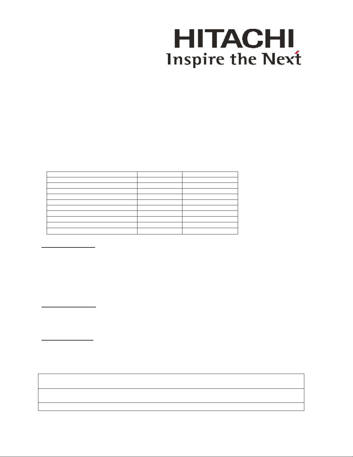
Quick installation guide
Hitachi Ultrastar 15K73
Ultra320 SCSI Hard disk drive
Model Numbers: 68 Pin Interface: HUS157373EL3600 HUS157336EL3600
80 Pin Interface: HUS157373EL3800 HUS157336EL3800
SPECIFICATIONS
Formatted Capacity*(Gbytes) 73.9 GB 36.9 GB
Bytes per Sector* 512 512
#Cylinders/#Heads/#Disks 40664/10/5 40664/5/3
Maximum LBA*(Hex) 89B88FF 44DC47F
Seektime:Average(Read. Typical) 3.9/4.2 3.9/4.2
Spindle Speed rpm 15037 15037
Interface Type Ultra 320 Ultra 320
Transfer rate (MB/s) 320.0 max 320.0 max
Operating Temperature (C/F)
Power: 12Vpeak(Typ)/5V peak (Typ) (A) 2.20/1.54 2.20/1.54
Start Time(s) 25 25
Handling Precautions
1. Do not press on the drive. Hold the drive by the sides only, do not apply any force to the drive during
handling or installation.
2. Always handle the drive with care to prevent damage from shock, vibration or electrostatic
discharge(ESD). Do not touch the Printed Circuit Board (PCB).
3. Electrostatic Discharge. Static electricity can damage the drive. Before handling the drive, touch an
unpainted metal surface for a few seconds to drain any static electricity from your body.
4. Keep the original packaging and static-protective bag in case the drive has to be returned.
Mounting Orientation
1. Installation horizontal or vertical ( 6 directions)
2. Provide adequate air flow to cool drive
3. Use 4 mounting screws (6x32 UNC). Maximum screw penetration 3.8mm (0.15 in) into drive
Cable Specifications:
1. Use interface cables that meet the ANSI SCSI guideline.
2. Cable length:
Interface cable (NW, Single-ended mode)
Cable Type Maximum cable length
Fast-5 Fast-10 Ultra(Fast20)
SCSI Interface Flat Ribbon or 6m 3m 3m(4 units max.)
Twisted Pair (16 units max.) (16 units max.) 1.5m (8 units max.)
DC power supply AWG#20 3m
5-55°C
5-55°C
7/28/2003
v1.0
1
Page 2
Interface cable (NW, LVD mode)
Cable Type Maximum cable length
Ultra2(Fast)-40,Ultra160(Fast-80),Ultra 320(Fast-160)
SCSI Interface Flat Ribbon or 12m (16 units max.)
Twisted Pair
DC power supply AWG#20 3m
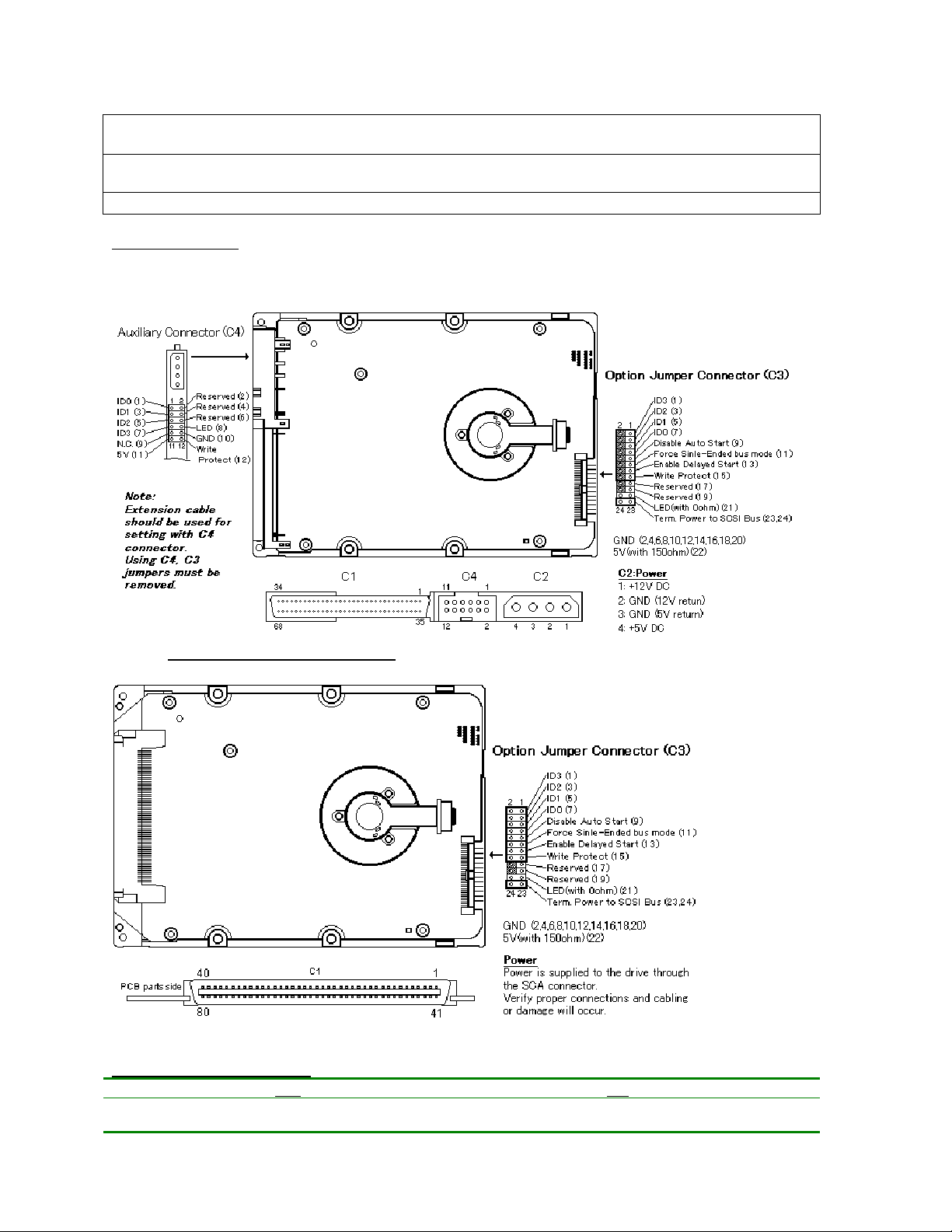
Connector Layout:
Wide LVD 68pin-16bits (NW)
SCA-2 LVD 80 pin-16bits (NC)
Option Jumper Connector C3
NW
Pin Function Removed Installed Function Removed Installed
1-2 ID3 * ID3 *
7/28/2003
v1.0
NC
2
Page 3

3-4 ID2 * ID2 *
5-6 ID1 * ID1 *
7-8 ID0 * ID0 *
9-10 Disable Auto Start At power on per
11-12 Force SE bus
mode
13-14 Enable delay start At power on* In 10 sec x ID
15-16 Write Protect Write Enable* Write Protected Write Protect Write Enable* Write Protected
17-18 Reserved Reserved
19-20 Reserved Reserved
21-22 LED(with 0 Ohm) LED(with 0 Ohm)
23-24 Term Power Termpwr not to
C3 pins 13-14
Single-ended or
LVD mode*
SCSI Bus*
Only by SCSI
Command
Only by SCSI
Command
intervals on power
on
Termpwr to SCSI
bus
Disable Auto Start Refer note3 below Only by SCSI
Force SE bus
mode
Enable delay start At power on* In 10 sec x ID
Term Power Termpwr not to
Single-ended or
LVD mode*
SCSI Bus*
Command
Only by SCSI
Command
intervals on power
on
Termpwr to SCSI
bus
• Indicates Default Settings. Do not Change the reserved jumper pins! Changing will void warranty! Spare
jumpers C3: 2-4, 6-8, 12-14-16,18-20 for NW model, C3: 18-20 for NC model.. These spare jumpers can be used
for another setting.
7/28/2003
v1.0
3
Page 4

© Copyright Hitachi Global Storage Technologies
Hitachi Global Storage Technologies
5600 Cottle Road
San Jose, CA 95193
Produced in the United States
7/03
All rights reserved Travelstar™ is a trademark of
Hitachi Global Storage Technologies.
Microsoft, Windows XP, and Windows are trademarks of
Microsoft Corporation in the United States, other
countries, or both.
Other product names are trademarks or registered trademarks of their respective companies.
References in this publication to Hitachi Global Storage
Technologies products, programs or services do not imply
that Hitachi Global Storage Technologies intends to make
these available in all countries in which Hitachi Global
Storage Technologies operates.
Product information is provided for information purposes
only and does not constitute a warranty.
Information is true as of the date of publication and is
subject to change. Actual results may vary.
This publication is for general guidance only. Photographs may show design models.
28 July 2003
7/28/2003
v1.0
4
 Loading...