

Hitachi 15K450, HUS154545VLF400, HUS154530VLF400 User Manual
Hard Disk Drive Specification
Ultrastar 15K450
3.5 inch 4Gb FC-AL Hard Disk Drive
Models: HUS154545VLF400
HUS154530VLF400
Version 1.2 29 October 2008
Warning: Printed copies of this document are considered current only on the date of print. Replacement and disposal
of down-level versions is the responsibility of the document holder.
Hitachi Ultrastar 15K450 (FC-AL) Hard Disk Drive Specification

3rd Edition (Rev. 1.2) (29 October 2008)
The following paragraph does not apply to the United Kingdom or any country where such provisions are inconsistent
with local law: HITACHI GLOBAL STORAGE TECHNOLOGIES PROVIDES THIS PUBLICATION "AS IS"
WITHOUT WARRANTY OF ANY KIND, EITHER EXPRES S OR IMPLIED, INCLUDING, BUT NOT LIMITED
TO, THE IMPLIED WARRANTIES OF MERCHANTABILITY OR FITNESS FOR A PARTICULAR PURPOSE.
Some states do not allow disclaimer or express or implied warranties in certain transactions, therefore, this statement
may not apply to you.
This publication could include technical inaccuracies or typographical errors. Changes are periodically made to the information herein; these changes will be incorporated in new editions of the publication. Hitachi may make improvements or changes
in any products or programs described in this publication at any time.
It is possible that this publication may contain reference to, or information about, Hitachi products (machines and programs),
programming, or services that are not announced in your country. Such references or information must not be construed to
mean that Hitachi intends to announce such Hitachi products, programming, or services in your country.
T echnical information about this product is available by contacting your local Hitachi Global Storage Technologies representative or on the Internet at http://www.hitachigst.com
Hitachi Global Storage Technologies may have patents or pending patent applications covering subject matter in this document. The furnishing of this document does not give you any license to these patents.
©Copyright Hitachi Global Storage Technologies
Note to U.S. Government Users —Documentation related to restricted rights —U se, dup lication or disclosure is subject to
restrictions set forth in GSA ADP Schedule Contract with Hitachi Global Storage Technologies.
Hitachi Ultrastar 15K450 (FC-AL) Hard Disk Drive Specification

Table of Contents
1.0 General............................................................................................................................1
1.1 Introduction................................................................................................................1
1.2 Glossary .....................................................................................................................1
1.3 Caution.......................................................................................................................1
2.0 Outline of the Drive .......................................................................................................3
3.0 Fixed-disk Subsystem Description ...............................................................................5
3.1 Control Electronics ....................................................................................................5
3.2 Head Disk Assembly .................................................................................................5
3.3 Actuator .....................................................................................................................5
4.0 Drive Characteristics.....................................................................................................7
4.1 Formatted Capacity....................................................................................................7
4.2 Data Sheet..................................................................................................................7
4.3 Inquiry Information....................................................................................................8
4.3.1 Product ID.........................................................................................................8
4.3.2 World Wide ID - Block Assignment ................................................................8
4.4 Cylinder allocation.....................................................................................................9
4.5 Performance characteristics.......................................................................................10
4.5.1 Mechanical positioning.....................................................................................11
4.5.2 Drive ready time ...............................................................................................13
4.5.3 Spindle stop time ..............................................................................................13
4.5.4 Data transfer speed............................................................................................13
4.5.5 Buffering operation (read ahead/write cache)...................................................14
5.0 Data Integrity.................................................................................................................15
5.1 Equipment Status.......................................................................................................15
5.2 Error Recovery Procedure..........................................................................................15
6.0 Physical Format .............................................................................................................17
6.1 Shipped Format (P-List) ............................................................................................17
6.2 Reassigned Format (G-List).......................................................................................17
7.0 Electrical Interface.........................................................................................................19
7.1 FC-AL Connector ......................................................................................................19
7.1.1 40 pin SCA-2 SFF-8045 FC-AL Connector Definition....................................19
7.1.2 Voltage and Ground Signals.............................................................................20
7.1.3 Fault LED Out ..................................................................................................20
7.1.4 Ready LED Out ................................................................................................20
7.1.5 Start Mated Controls.........................................................................................21
7.1.6 SEL_n and Enclosure Service Signals..............................................................21
7.1.7 –ENBL_BYP CH1, -ENBL_BYP_CH2..........................................................23
7.1.8 –Drive Present..................................................................................................23
7.1.9 Dev_Ctrl_Code_x.............................................................................................23
8.0 Environment...................................................................................................................25
8.1 Temperature and humidity.........................................................................................25
8.2 Storage requirements .................................................................................................26
Hitachi Ultrastar 15K450 (FC-AL) Hard Disk Drive Specification

8.2.1 Packaging..........................................................................................................26
8.2.2 Storage time......................................................................................................26
8.3 Corrosion test.............................................................................................................26
8.4 Cooling requirements.................................................................................................27
9.0 DC Power Requirements...............................................................................................29
9.1 Power Supply Current, Average and Peak.................................................................30
9.2 Ripple Voltage...........................................................................................................32
9.3 Power Consumption Efficiency Index.......................................................................32
10.0 Reliability......................................................................................................................33
10.1 Start/Stop Cycles......................................................................................................33
10.2 Data Reliability........................................................................................................33
10.3 Seek errors ...............................................................................................................33
10.4 Failure prediction (PFA/S.M.A.R.T).......................................................................33
10.5 Preventive Maintenance...........................................................................................33
10.6 Temperature Warning..............................................................................................33
11.0 Mechanical Specifications..........................................................................................35
11.1 Outline .....................................................................................................................35
11.2 Mechanical Dimensions...........................................................................................35
11.3 Interface Connector..................................................................................................37
11.4 Mounting Positions and Tappings ...........................................................................38
11.5 Drive Mounting........................................................................................................40
11.6 Heads Unload and Actuator Lock............................................................................40
12.0 Vibration and Shock....................................................................................................41
12.1 Operating Vibration.................................................................................................41
12.1.1 Random Vibration...........................................................................................41
12.1.2 Swept Sine Vibration.....................................................................................41
12.2 Non-operating Vibrations ........................................................................................41
12.2.1 Random Vibration..........................................................................................41
12.2.2 Swept Sine Vibration.....................................................................................41
12.3 Operating shock......................................................................................................41
12.4 Non-operating shock...............................................................................................42
12.4.1 Half sinewave shock pulse..............................................................................42
12.4.2 Rotational shock ............................................................................................42
13.0 Acoustics.......................................................................................................................43
13.1 Sound power levels..................................................................................................43
14.0 Identification ................................................................................................................45
14.1 Labels.......................................................................................................................45
15.0 Electromagnetic Compatibility...................................................................................47
15.1 Class A Regulatory Notices.....................................................................................48
16.0 Standards......................................................................................................................51
16.1 UL and C-UL Standard Conformity........................................................................51
16.2 European Standards Compliance.............................................................................51
16.3 German Safety Mark................................................................................................51
16.4 Flammability............................................................................................................51
16.5 Corporate Standards Compliance ............................................................................51
17.0 FC-AL attachment.......................................................................................................53
Hitachi Ultrastar 15K450 (FC-AL) Hard Disk Drive Specification

17.1 Fundamentals...........................................................................................................53
17.1.1 Node and Port names......................................................................................54
17.1.2 NL_Port address .............................................................................................54
17.1.3 Primitive signals and sequences .....................................................................55
17.1.4 Frames............................................................................................................56
17.1.5 Sequences........................................................................................................56
17.1.6 Exchanges.......................................................................................................57
17.2 Basic Link Services .................................................................................................57
17.2.1 Abort sequence (ABTS).................................................................................57
17.2.2 Basic accept (BA_ACC).................................................................................58
17.2.3 Basic reject (BA_RJT)....................................................................................59
17.3 Extended Link Services ...........................................................................................60
17.3.1 Link Service Accept (LS_ACC)....................................................................61
17.3.2 Link Service Reject (LS_RJT).......................................................................62
17.3.3 Port Login (PLOGI).......................................................................................63
17.3.4 Logout (LOGO).............................................................................................71
17.3.5 Fabric Login (FLOGI) ...................................................................................72
17.3.6 Fabric Address Notification (FAN)...............................................................76
17.3.7 Port Discovery (PDISC) ................................................................................77
17.3.8 Address Discovery (ADISC) .........................................................................77
17.3.9 Process Login (PRLI) ....................................................................................78
17.3.10 Process Logout (PRLO)...............................................................................82
17.3.11 Read Link Error Status Block (RLS)...........................................................84
17.3.12 Report Node Capabilities (RNC).................................................................85
17.3.13 Re-instate Recovery Qualifiers (RRQ)........................................................89
17.3.14 Third Party Process Logout (TPRLO).........................................................90
17.3.15 Request Node Identification Data (RNID) ...................................................92
17.3.16 Report Port Speed Capabilities (RPSC)........................................................95
17.4 Common Fibre Channel Services ............................................................................95
17.4.1 Register FC-4 Types (RFT_ID)......................................................................98
17.5 FC-AL timers...........................................................................................................100
17.5.1 Link Failure.....................................................................................................101
17.6 Invalid frame delimiter ............................................................................................101
18.0 SCSI-FCP .....................................................................................................................103
18.1 Terminology.............................................................................................................103
18.2 Information Units.....................................................................................................104
18.2.1 FCP_CMND ...................................................................................................105
18.2.2 FCP_XFER_RDY...........................................................................................107
18.2.3 FCP_DATA ....................................................................................................107
18.2.4 FCP_RSP ........................................................................................................107
18.3 Task Attributes.........................................................................................................109
18.4 Task Management functions....................................................................................110
18.4.1 Abort Task (Implemented as ABTS BLS).....................................................111
18.4.2 Abort Task Set ................................................................................................111
18.4.3 Terminate Task ...............................................................................................112
18.4.4 Clear ACA ......................................................................................................112
Hitachi Ultrastar 15K450 (FC-AL) Hard Disk Drive Specification

18.4.5 Target Reset....................................................................................................112
18.4.6 Clear Task Set.................................................................................................112
18.4.7 Reset LUN ......................................................................................................112
18.5 Miscellaneous ..........................................................................................................112
18.5.1 Tags.................................................................................................................112
18.5.2 Auto-Contingent Allegiance (ACA)...............................................................112
18.5.3 Autosense.......................................................................................................113
19.0 SCSI Command Set ....................................................................................................115
19.1 SCSI Control Byte ...................................................................................................117
19.2 Abbreviations...........................................................................................................117
19.3 Byte ordering conventions.......................................................................................117
19.4 FORMAT UNIT (04)...............................................................................................118
19.4.1 Parameter List Header ....................................................................................120
19.4.2 Defect Descriptor............................................................................................121
19.5 INQUIRY (12).........................................................................................................125
19.5.1 Inquiry Data....................................................................................................126
19.6 LOG SELECT (4C) .................................................................................................137
19.7 LOG SENSE (4D) ...................................................................................................140
19.7.1 Log Page parameters.......................................................................................141
19.7.2 Log Sense Page 0............................................................................................142
19.7.3 Log Sense Page 2............................................................................................143
19.7.4 Log Sense Page 3............................................................................................145
19.7.5 Log Sense Page 5............................................................................................147
19.7.6 Log Sense Page 6............................................................................................149
19.7.7 Log Sense Page D...........................................................................................150
19.7.8 Log Sense Page E ...........................................................................................151
19.7.9 Log Sense Page F............................................................................................152
19.7.10 Log Sense Page 10........................................................................................153
19.7.11 Log Sense Page 15........................................................................................156
19.7.12 Log Sense Page 2F........................................................................................159
19.7.13 Log Sense Page 30........................................................................................160
19.7.14 Log Sense Page 37........................................................................................163
19.8 MODE SELECT (15) ..............................................................................................165
19.9 MODE SELECT (55) ..............................................................................................166
19.10 MODE SENSE (1A)..............................................................................................167
19.10.1 Mode Parameter List.....................................................................................168
19.10.2 Mode Page 00 (Vendor Unique Parameters)................................................172
19.10.3 Mode Page 01 (Read/Write Error Recovery Parameters).............................174
19.10.4 Mode Page 02 (Disconnect/Reconnect Parameters).....................................179
19.10.5 Mode Page 03 (Format Device Parameters).................................................180
19.10.6 Mode Page 04 (Rigid Disk Drive Geometry Parameters) ............................182
19.10.7 Mode Page 07 (Verify Error Recovery Parameters).....................................183
19.10.8 Mode Page 08 (Caching Parameters)............................................................184
19.10.9 Mode Page 0A (Control Mode Page Parameters).........................................186
19.10.10 Control Extension Subpage ........................................................................187
19.10.11 Mode Page 0C (Notch Parameters) ............................................................188
Hitachi Ultrastar 15K450 (FC-AL) Hard Disk Drive Specification

19.10.12 Mode Page 19h (Fibre Channel Port Control Page) ...................................190
19.10.13 Mode Page 1A (Power Control) .................................................................192
19.10.14 Mode Page 1C (Informational Exceptions Control)...................................193
19.11 MODE SENSE (5A)..............................................................................................196
19.12 PERSISTENT RESERVE IN (5E)........................................................................197
19.12.1 Service Action...............................................................................................198
19.12.2 Parameter data for Read Keys ......................................................................199
19.12.3 Parameter Data for Read Reservations.........................................................200
19.13 PERSISTENT RESERVE OUT (5F) ....................................................................201
19.13.1 Service Action...............................................................................................202
19.13.2 Type..............................................................................................................203
19.13.3 Parameter list ................................................................................................204
19.13.4 Summary.......................................................................................................205
19.14 PRE-FETCH (34) ..................................................................................................207
19.15 READ (6) - (08).....................................................................................................208
19.16 READ (10) - (28)...................................................................................................209
19.17 READ (12) - (A8)..................................................................................................211
19.18 READ (16) - (88)...................................................................................................212
19.19 READ (32) - (7F/09)..............................................................................................213
19.20 READ BUFFER (3C)............................................................................................215
19.20.1 Combined Header And Data (Mode 00000b)...............................................216
19.20.2 Read Data (Mode 00010b)............................................................................217
19.20.3 Descriptor (Mode 00011b)............................................................................218
19.20.4 Read Data from Echo Buffer (Mode 01010b) ..............................................219
19.20.5 Echo Buffer Descriptor (Mode 01011b).......................................................220
19.20.6 Enable Expander Communications Protocol and Echo Buffer (Mode11010b)..221
19.21 READ CAPACITY (10) - (25)..............................................................................222
19.22 READ CAPACITY (16) (9E/10)...........................................................................224
19.22.1 Returned Data Format...................................................................................225
19.23 READ DEFECT DATA (37).................................................................................226
19.23.1 Defect List Header........................................................................................228
19.23.2 Defect List Descriptor...................................................................................229
19.23.3 Bytes from Index Format (100b) ..................................................................230
19.23.4 Physical Sector Format (101b) .....................................................................231
19.24 READ DEFECT DATA (B7)................................................................................232
19.24.1 Defect List Header........................................................................................233
19.24.2 Defect List Descriptor...................................................................................234
19.24.3 Bytes from Index Format (100b) ..................................................................235
19.24.4 Physical Sector Format (101b) .....................................................................236
19.25 READ LONG (3E) ................................................................................................237
19.26 REASSIGN BLOCKS (07) ...................................................................................238
19.27 RECEIVE DIAGNOSTICS RESULTS (1C) ........................................................240
19.27.1 Receive Diagnostic Results Page 0...............................................................241
19.27.2 Enclosure Service Information (ESI) Page Format ......................................242
19.27.3 Receive Diagnostic Results Page 40.............................................................243
19.27.4 Receive Diagnostic Page A0h.......................................................................245
Hitachi Ultrastar 15K450 (FC-AL) Hard Disk Drive Specification

19.28 RELEASE (17) ......................................................................................................246
19.29 RELEASE (57) ......................................................................................................247
19.30 REPORT DEVICE IDENTIFIER (A3/05)............................................................248
19.31 REPORT LUNS (A0)............................................................................................250
19.32 REPORT SUPPORTED OPERATION CODES (A3/0C)....................................251
19.32.1 All_commands parameter data format..........................................................253
19.32.2 One_command parameter data format..........................................................254
19.33 REPORT SUPPORTED TASK MANAGEMENT FUNCTIONS (A3/0D).........255
19.34 REQUEST SENSE (03).........................................................................................257
19.35 RESERVE (16)......................................................................................................258
19.36 RESERVE (56)......................................................................................................259
19.37 REZERO UNIT (01)..............................................................................................260
19.38 SEEK (6) - (0B).....................................................................................................261
19.39 SEEK (10) - (2B)...................................................................................................261
19.40 SEND DIAGNOSTIC (1D)...................................................................................262
19.40.1 Send Diagnostic Page 0 ................................................................................264
19.40.2 Send Diagnostic Page 40 ..............................................................................265
19.40.3 Send Diagnostic Page A0h ...........................................................................267
19.41 SET DEVICE IDENTIFIER (A4/06)....................................................................268
19.42 START STOP UNIT (1B).....................................................................................269
19.43 SYNCHRONIZE CACHE (10) - (35)...................................................................270
19.44 SYNCHRONIZE CACHE (16) - (91)...................................................................271
19.45 TEST UNIT READY (00).....................................................................................272
19.46 VERIFY (2F).........................................................................................................273
19.47 VERIFY (12) - (AF) ..............................................................................................276
19.48 VERIFY (16) - (8F)...............................................................................................277
19.49 VERIFY (32) - (7F/0A).........................................................................................278
19.50 WRITE (6) - (0A) ..................................................................................................280
19.51 WRITE (10) - (2A) ................................................................................................281
19.52 WRITE (12) - (AA) ...............................................................................................284
19.53 WRITE (16) - (8A) ................................................................................................285
19.54 WRITE (32) - (7F/0B)...........................................................................................286
19.55 WRITE AND VERIFY (10) - (2E)........................................................................288
19.56 WRITE AND VERIFY (12) - (AE).......................................................................289
19.57 WRITE AND VERIFY (16) - (8E)........................................................................290
19.58 WRITE AND VERIFY (32) - (7F/0C)..................................................................291
19.59 WRITE BUFFER (3B) ..........................................................................................293
19.59.1 Combined Header And Data (Mode 00000b)...............................................294
19.59.2 Write Data (Mode 00010b)...........................................................................295
19.59.3 Download Microcode (Mode 00100b) .........................................................296
19.59.4 Download Microcode and Save (Mode 00101b) -Single Binary File ..........297
19.59.5 Download Microcode and Save (Mode 00111b) - Multiple Binary Files....298
19.59.6 Write Data to Echo Buffer (Mode 01010b)..................................................299
19.59.7 Enable Expander Communications Protocol (Mode 11010b)......................300
19.60 WRITE LONG (3F)...............................................................................................301
19.61 WRITE SAME (41)...............................................................................................302
Hitachi Ultrastar 15K450 (FC-AL) Hard Disk Drive Specification

19.62 WRITE SAME (16) - (93).....................................................................................303
19.63 WRITE SAME (32) - (7F/0D)...............................................................................304
20.0 SCSI Status Byte..........................................................................................................307
21.0 Additional information...............................................................................................309
21.1 Obtaining an AL_PA ...............................................................................................309
21.2 Loop Initialization Procedure ..................................................................................309
21.3 Flow Control............................................................................................................311
21.4 Login Requirements.................................................................................................311
21.5 Public Loop Operation.............................................................................................312
21.5.1 NL_Port Initialization.....................................................................................313
21.6 SCSI Protocol ..........................................................................................................315
21.6.1 Priority of SCSI Status Byte Reporting..........................................................315
21.6.2 Invalid LUN Processing..................................................................................315
21.6.3 Overlapped Commands...................................................................................315
21.6.4 Command Processing During Execution of Active I/O Process ....................316
21.6.5 Unit Attention Condition ................................................................................317
21.6.6 Command Processing During Startup and Format Operations.......................319
21.6.7 Internal Error Condition..................................................................................319
21.6.8 Deferred Error Condition................................................................................319
21.6.9 Degraded Mode...............................................................................................320
21.6.10 Command Processing while Reserved..........................................................327
21.7 Priority Commands..................................................................................................327
21.8 Command Queuing..................................................................................................328
21.8.1 Queue Depth ...................................................................................................328
21.8.2 Queue Full Status............................................................................................328
21.8.3 Effects of LIP on Command Queuing ............................................................328
21.8.4 Termination of I/O Processes .........................................................................328
21.9 Command Reordering..............................................................................................328
21.10 Concurrent I/O Process..........................................................................................328
21.11 Write Cache ...........................................................................................................329
21.12 Automatic Rewrite/Reallocate...............................................................................329
21.13 Segmented Caching ...............................................................................................331
21.13.1 Overview.......................................................................................................331
21.13.2 Read Ahead...................................................................................................331
21.14 Multiple Initiator Systems .....................................................................................331
21.14.1 Sense Data.....................................................................................................331
21.14.2 Mode Pages...................................................................................................331
21.15 Enclosure Services.................................................................................................331
21.15.1 Enclosure Initiated ESI.................................................................................332
21.16 Multiple Initiator Environment..............................................................................332
21.16.1 Initiator Sense Data.......................................................................................332
21.16.2 Initiator Mode Select/Mode Sense Parameters.............................................332
21.17 Reset.......................................................................................................................332
21.17.1 Reset Sources................................................................................................333
21.17.2 Reset Actions................................................................................................333
21.18 Diagnostics.............................................................................................................333
Hitachi Ultrastar 15K450 (FC-AL) Hard Disk Drive Specification

21.18.1 Power on Diagnostics ...................................................................................333
21.18.2 Self-test via SEND DIAGNOSTIC Command.............................................334
21.19 Idle Time Function.................................................................................................337
21.20 Command Time out Limits ...................................................................................337
21.20.1 Reassignment Time.......................................................................................337
21.20.2 Format Time .................................................................................................337
21.20.3 Start/Stop Unit Time.....................................................................................337
21.20.4 Medium Access Command Time .................................................................338
21.20.5 Time-out Limits for Other Commands.........................................................338
21.21 Recommended Initiator ERP .................................................................................339
21.21.1 Drive Service Strategy..................................................................................339
21.21.2 Recommendations for System Error Log .....................................................340
21.21.3 Data Recovery Procedure .............................................................................340
21.21.4 Nondata Error Recovery Procedure..............................................................342
22.0 SCSI Sense Data...........................................................................................................349
22.1 SCSI Sense Data Format..........................................................................................349
22.2 Sense Data Description............................................................................................350
22.2.1 Valid (Bit 7 of byte 0).....................................................................................350
22.2.2 Error Code (Bit 6 - 0 of byte 0) ......................................................................350
22.2.3 ILI: Incorrect Length Indicator (Bit 5 of byte 2) ............................................350
22.2.4 Sense Key (Bit 3 - 0 of byte 2) .......................................................................351
22.2.5 Information Bytes (Byte 3 through 6).............................................................352
22.2.6 Additional Sense Length (Byte 7) ..................................................................352
22.2.7 Command Specific Information (Byte 8 through 11).....................................352
22.2.8 Additional Sense Code/Qualifier (Byte 12 and 13)........................................353
22.2.9 RU: Field Replaceable Unit (Byte 14)...........................................................371
22.2.10 Sense Key Specific (Byte 15 through 17).....................................................371
22.2.11 Reserved (Byte 18 through 19).....................................................................374
22.2.12 Vendor unique error information (Byte 20 through 23) ...............................374
22.2.13 Physical Error Record (Byte 24 thru 29) ......................................................374
22.2.14 Reserved (Byte 30 through 31).....................................................................374
23.0 Appendix. UEC list.....................................................................................................375
Hitachi Ultrastar 15K450 (FC-AL) Hard Disk Drive Specification

List of Tables
Table 1.Product ID table............................................................................................1
Table 2.Formatted Capacity.......................................................................................7
Table 3.Data Sheet.....................................................................................................7
Table 4.Product ID in Inquiry Command..................................................................8
Table 5.Block assignment of World Wide ID in INQUIRY Command....................8
Table 6.Cylinder allocation........................................................................................9
Table 7.Mechanical positioning performance ...........................................................11
Table 8.Latency time .................................................................................................12
Table 9.Drive ready time ...........................................................................................13
Table 10.Spindle stop time ........................................................................................13
Table 11.Data transfer speed (sector size 512 Byte case)..........................................13
Table 12.Operating and non-operating conditions ....................................................25
Table 13.Maximum allowable surface temperatures.................................................27
Table 14.Input Voltage ..............................................................................................29
Table 15.Power Supply Generated Ripple at Drive Power Connector......................32
Table 16.Power Consumption Efficiency Index........................................................32
Table 17.Physical Dimensions...................................................................................35
Table 18.A-weighted sound power levels..................................................................43
Table 19.IEEE Registered Name format ...................................................................54
Table 20.NL_Port address .........................................................................................54
Table 21.General frame format..................................................................................56
Table 22.Frame header ..............................................................................................56
Table 23.Basic link service command codes.............................................................57
Table 24.BA_ACC Payload.......................................................................................58
Table 25. BA_RJT Payload .......................................................................................59
Table 26.BA_RJT Reason Codes ..............................................................................59
Table 27.BA_RJT Reason Code Explanations..........................................................59
Table 28.Extended Link Service replies....................................................................60
Table 29.Extended Link Service requests..................................................................60
Table 30.Extended Link Service request 11h qualifiers............................................61
Table 31.LS_RJT payload .........................................................................................62
Table 32.LS_RJT reason codes .................................................................................62
Table 33.LS_RJT reason code explanations..............................................................63
Table 34.PLOGI_REQ/PLOGI_ACC payload..........................................................64
Table 35.Common Service Parameter applicability (part 1 of 2)..............................65
Table 36.Common Service Parameter applicability (part 2 of 2)..............................66
Table 37.FC-PH Version ...........................................................................................66
Table 38.Class Service Parameters............................................................................68
Table 39.LOGO payload............................................................................................71
Table 40.LOGO ACC payload ..................................................................................71
Table 41.FLOGI_REQ/FLOGI_ACC payload .........................................................72
Table 42.Common Service Parameters (FLOGI_REQ/FLOGI_ACC).....................73
Table 43.Class Service Parameters............................................................................75
Table 44.FAN payload...............................................................................................76
Hitachi Ultrastar 15K300 (FC-AL) Hard Disk Drive Specification

Table 45.ADISC payload...........................................................................................77
Table 46.ADISC ACC payload .................................................................................78
Table 47.PRLI payload..............................................................................................78
Table 48.PRLI ACC payload.....................................................................................79
Table 49.Login Service Parameter page....................................................................79
Table 50.Login Response Service Parameter page....................................................81
Table 51.PRLI/PRLO ACC response codes..............................................................82
Table 52.PRLO payload ............................................................................................82
Table 53.PRLO ACC payload ...................................................................................83
Table 54.Logout Service Parameter page..................................................................83
Table 55.Logout Response Service Parameter page..................................................84
Table 56.RLS payload ...............................................................................................85
Table 57.RLS ACC payload......................................................................................85
Table 58.Link Error Status block...............................................................................85
Table 59.RNC/ACC payload.....................................................................................86
Table 60.RNC Capability Entry.................................................................................87
Table 61.Document Identifiers ..................................................................................88
Table 62.RRQ payload ..............................................................................................89
Table 63.RRQ ACC payload .....................................................................................89
Table 64.TPRLO payload..........................................................................................90
Table 65.TPRLO ACC payload.................................................................................90
Table 66.Logout Service Parameter page..................................................................90
Table 67.Logout Response Service Parameter page..................................................91
Table 68.RNID payload.............................................................................................92
Table 69.RNID accept payload..................................................................................92
Table 70.Common Node Identification Data.............................................................93
Table 71.Topology Discovery Specific Node Identification Data.............................93
Table 72.Topology Discovery Unit Type..................................................................94
Table 73.Topology Discovery Flags..........................................................................95
Table 74.RPSC payload.............................................................................................95
Table 75.RPSC ACC payload....................................................................................95
Table 76.Payload of a CT Header..............................................................................96
Table 77.Command/Response Codes ........................................................................96
Table 78.RFT_ID payload.........................................................................................98
Table 79.RFT_ID ACC/RJT payload........................................................................98
Table 80.FS_RJT Reason Codes ...............................................................................99
Table 81.FS_RJT Reason Explanations.....................................................................99
Table 82.FCAL timer values .....................................................................................100
Table 83.Information Units (IUs)..............................................................................104
Table 84.FCP_CMND payload..................................................................................105
Table 85.FCP_CNTL field ........................................................................................105
Table 86.Task Attribute values..................................................................................105
Table 87.TMF flag values..........................................................................................106
Table 88.FCP_XFER_RDY payload.........................................................................107
Table 89.FCP_RSP payload ......................................................................................107
Table 90.FCP_STATUS field....................................................................................108
Hitachi Ultrastar 15K300 (FC-AL) Hard Disk Drive Specification

Table 91.FCP_RSP_INFO field ................................................................................109
Table 92.RSP_CODE definitions ..............................................................................109
Table 93.Task Management function RSP_CODE definitions .................................110
Table 94.SCSI Commands Supported .......................................................................115
Table 95.SCSI Control Byte......................................................................................117
Table 96.FORMAT UNIT (04) .................................................................................118
Table 97.Format of the Parameter List Header..........................................................120
Table 98.Initialization Pattern Descriptor:.................................................................121
Table 99.Defect Descriptor - Block Format (for n + 1 defects) ................................122
Table 100.Defect Descriptor - Bytes From Index Format (for n = 1 defects)...........123
Table 101.Defect Descriptor - Physical Sector Format (for n + 1 defects) ...............124
Table 102.INQUIRY (12)..........................................................................................125
Table 103.Page Code descriptions.............................................................................125
Table 104.Inquiry Data- EVPD = 0...........................................................................126
Table 105.Inquiry Data - EVPD = 1 (Page Code = 00h)...........................................128
Table 106.Inquiry Data - EVPD = 1 (Page Code = 03h)...........................................129
Table 107.Inquiry Data - EVPD = 1 (Page Code = 80h)...........................................131
Table 108.Inquiry Data - EVPD = 1 (Page Code = 83h)...........................................132
Table 109.Inquiry Data - EVPD = 1 (Page Code = D1h)..........................................135
Table 110.Inquiry Data - EVPD = 1 (Page Code = D2h)..........................................136
Table 111.Log Select (4C).........................................................................................137
Table 112.Log Sense (4D).........................................................................................140
Table 113.Log Sense Page 0......................................................................................142
Table 114.Log Sense Page 2 (part 1 of 2)..................................................................143
Table 115.Log Sense Page 2 (part 2 of 2)..................................................................143
Table 116.Log Sense Page 3 (part 1 of 2)..................................................................145
Table 117.Log Sense Page 3 (part 2 of 2)..................................................................145
Table 118.Log Sense Page 5 (part 1 of 2)..................................................................147
Table 119.Log Sense Page 5 (part 2 of 2)..................................................................148
Table 120.Log Sense Page 6......................................................................................149
Table 121.Log Sense Page D.....................................................................................150
Table 122.Log Sense Page E .....................................................................................151
Table 123.Log Sense Page F......................................................................................152
Table 124.Log Sense Page F, Application Client Log ..............................................152
Table 125.Log Sense Page 10....................................................................................153
Table 126.Log Sense Page 10, self-test results..........................................................153
Table 127.Log Sense Page 10, self-test results..........................................................154
Table 128.Log Sense Page 10, Extended Segment Number......................................155
Table 129.Log Sense Page 15....................................................................................156
Table 130. Log Sense Page 2F...................................................................................159
Table 131.Log Sense Page 30....................................................................................160
Table 132.Log Sense Page 37....................................................................................163
Table 133.Mode Select (15).......................................................................................165
Table 134.Mode Select (55).......................................................................................166
Table 135.Mode Sense (1A)......................................................................................167
Table 136.Page Code Usage......................................................................................168
Hitachi Ultrastar 15K300 (FC-AL) Hard Disk Drive Specification

Table 137.Mode parameter header (6).......................................................................168
Table 138.Mode parameter header (10).....................................................................169
Table 139.Mode Parameter Block Descriptor ...........................................................170
Table 140.Mode Parameter Page Format ..................................................................171
Table 141.Mode Parameter Page Format ..................................................................171
Table 142.Vendor Unique Parameters - Page 00.......................................................172
Table 143.Mode Page 01 (Vendor Unique Parameters)............................................174
Table 144.Mode Page 02 (Disconnect/Reconnect Parameters).................................179
Table 145.Mode Page 03 (Format Device Parameters).............................................180
Table 146.Mode Page 04 (Rigid Disk Drive Geometry Parameters) ........................182
Table 147.Mode Page 07 (Verify Error Recovery Parameters).................................183
Table 148.Page 08 (Caching Parameters)..................................................................184
Table 149.Page 0A (Control Mode Page Parameters)...............................................186
Table 150.Control Extension Subpage ......................................................................187
Table 151.Page 0C (Notch Parameters).....................................................................188
Table 152.Mode Page 19h .........................................................................................190
Table 153.Values for RR_TOV Units .......................................................................191
Table 154.Page 1A (Power Control)..........................................................................192
Table 155.Page 1C (Informational Exceptions Control) ...........................................193
Table 156.Background Control (Subpage 01h).........................................................195
Table 157.Mode Sense (5A)......................................................................................196
Table 158.Persistent Reserve In (5E) ........................................................................197
Table 159.PERSISTENT RESERVE IN, Service Action Codes..............................198
Table 160.PERSISTENT RESERVE IN, parameter data for Read Keys .................199
Table 161.PERSISTENT RESERVE IN, parameter data for Read Reservations.....200
Table 162.PERSISTENT RESERVE IN, Read Reservation Descriptor...................200
Table 163.PERSISTENT RESERVE OUT (5F).......................................................201
Table 164.PERSISTENT RESERVE OUT, Service Action Code............................202
Table 165.PERSISTENT RESERVE OUT, Type Code ...........................................203
Table 166.Parameter List...........................................................................................204
Table 167.PERSISTENT RESERVE OUT, Service Action, Parameters .................205
Table 168.APTPL and information held by a drive...................................................206
Table 169.PRE-FETCH (34) .....................................................................................207
Table 170.READ (6) - (08)........................................................................................208
Table 171.READ (10) - (28) .....................................................................................209
Table 172.Read (12) - (A8)........................................................................................211
Table 173.READ (16) - (88)......................................................................................212
Table 174.Read (32) - (7F/09)...................................................................................213
Table 175.READ BUFFER (3C)...............................................................................215
Table 176.Read Buffer Header..................................................................................216
Table 177.Read Buffer Description...........................................................................218
Table 178.Echo Buffer Descriptor.............................................................................220
Table 179.READ CAPACITY (10) - (25).................................................................222
Table 180.Format of READ CAPACITY command reply........................................223
Table 181.Read Capcity (16) (9E/10)........................................................................224
Table 182.Returned Data Format...............................................................................225
Hitachi Ultrastar 15K300 (FC-AL) Hard Disk Drive Specification

Table 183.READ DEFECT DATA (37)....................................................................226
Table 184.Defect List Format....................................................................................227
Table 185.Defect List Header....................................................................................228
Table 186.Defect List Descriptor...............................................................................229
Table 187.Defect Descriptors of Bytes from Index Format ......................................230
Table 188.Defect Descriptors of Physical Sector Format..........................................231
Table 189.READ DEFECT DATA (B7)...................................................................232
Table 190.Defect List Header....................................................................................233
Table 191.Defect List Descriptor...............................................................................234
Table 192.Defect Descriptors of Bytes from Index Format ......................................235
Table 193.Defect Descriptors of Physical Sector Format..........................................236
Table 194.READ LONG (3E) ...................................................................................237
Table 195.REASSIGN BLOCKS (07) ......................................................................238
Table 196.Format of Reassign Blocks data ...............................................................239
Table 197.RECEIVE DIAGNOSTIC RESULTS (1C) .............................................240
Table 198.Receive Diagnostic Results page 0...........................................................241
Table 199.Enclosure Page Support for Send and Receive Diagnostic Commands...242
Table 200.ESI Page Format.......................................................................................242
Table 201.Receive Diagnostic Results Page 40.........................................................243
Table 202.Translated address ....................................................................................243
Table 203.Device LED Control Page - Receive Diagnostic......................................245
Table 204.RELEASE (17).........................................................................................246
Table 205.RELEASE (57).........................................................................................247
Table 206.REPORT DEVICE IDENTIFIER (A3/05)...............................................248
Table 207.Report Device Identifier parameter list ....................................................249
Table 208.REPORT LUNS (A0)...............................................................................250
Table 209.LUN Reporting parameter list format.......................................................250
Table 210.Report Supported Tasks Management Functions (A3/0D) ......................255
Table 211.REQUEST SENSE (03) ...........................................................................257
Table 212.RESERVE (16).........................................................................................258
Table 213.RESERVE (56).........................................................................................259
Table 214.REZERO UNIT (01).................................................................................260
Table 215.SEEK (6) - (0B)........................................................................................261
Table 216.SEEK (10) - (2B)......................................................................................261
Table 217.SEND DIAGNOSTIC (1D)......................................................................262
Table 218.SEND DIAGNOSTIC Function Code (1D) .............................................263
Table 219.Diagnostic Page 0 .....................................................................................264
Table 220.Diagnostic Page 40 ...................................................................................265
Table 221.Address to translate...................................................................................266
Table 222.Device LED Control Page - Send Diagnostic...........................................267
Table 223.SET DEVICE IDENTIFIER (A4/06).......................................................268
Table 224.SET DEVICE IDENTIFIER, Parameter List...........................................268
Table 225.START STOP UNIT (1B)........................................................................269
Table 226.SYNCHRONIZE CACHE (10) - (35)......................................................270
Table 227.Synchronize Cache (16) - (91)..................................................................271
Table 228.TEST UNIT READY (00)........................................................................272
Hitachi Ultrastar 15K300 (FC-AL) Hard Disk Drive Specification

Table 229.VERIFY (2F)............................................................................................273
Table 230.Verify (12) - (AF).....................................................................................276
Table 231.Verify (16) - (8F)......................................................................................277
Table 232.Verify (32) - 7F/0A) .................................................................................278
Table 233.WRITE (6) - (0A).....................................................................................280
Table 234.WRITE (10) - (2A)...................................................................................281
Table 235.Write (12) - (AA)......................................................................................284
Table 236.Write (32) - (7F/0B)..................................................................................286
Table 237.WRITE AND VERIFY (10) - (2E) ..........................................................288
Table 238.Write andVerify (12) - (AE).....................................................................289
Table 239.Write and Verify (16) - (8E).....................................................................290
Table 240.Write and Verify (32) - (7F/0C) ...............................................................291
Table 241.WRITE BUFFER (3B) .............................................................................293
Table 242.Write Buffer Header .................................................................................294
Table 243.WRITE LONG (3F)..................................................................................301
Table 244.WRITE SAME (41)..................................................................................302
Table 245.Write Same (16) - (93)..............................................................................303
Table 246.Write Same (32) - (7F/0D) .......................................................................304
Table 247.SCSI Status Byte. Format of the SCSI STATUS byte. ...........................307
Table 248.LIxx Frame Payloads................................................................................310
Table 249.Response to Frames before PLOGI or PRLI............................................312
Table 250.Spindle Motor Degraded Mode - Disable Auto Start...............................321
Table 251.Spindle Motor Degraded Mode - Auto Start Delay/Spinning Up ............322
Table 252.Spindle Motor Degraded Mode - Spindle Start Failure............................323
Table 253.Spindle Motor Degraded Mode - Spindle Stopped by Unit Stop Command324
Table 254.Self Configuration Failure Degraded Mode ............................................325
Table 255.Format Command Failure Degraded Mode..............................................326
Table 256.Sense data combinations with auto/recommend rewrite/reallocate..........330
Table 257.Short and Extended Self-Test Description ...............................................336
Table 258.Recommend Reassign Errors....................................................................341
Table 259.Log Only Errors........................................................................................341
Table 260.Format of Sense Data................................................................................349
Table 261.Field Pointer Bytes ...................................................................................371
Table 262.Actual Retry Count...................................................................................372
Table 263.Progress Indication ...................................................................................373
Table 264.Unit Error Codes.......................................................................................375
Hitachi Ultrastar 15K300 (FC-AL) Hard Disk Drive Specification
1.0 General
1.1 Introduction
This document describes the specifications of the following Hitachi 3.5 inch FC-AL drives.
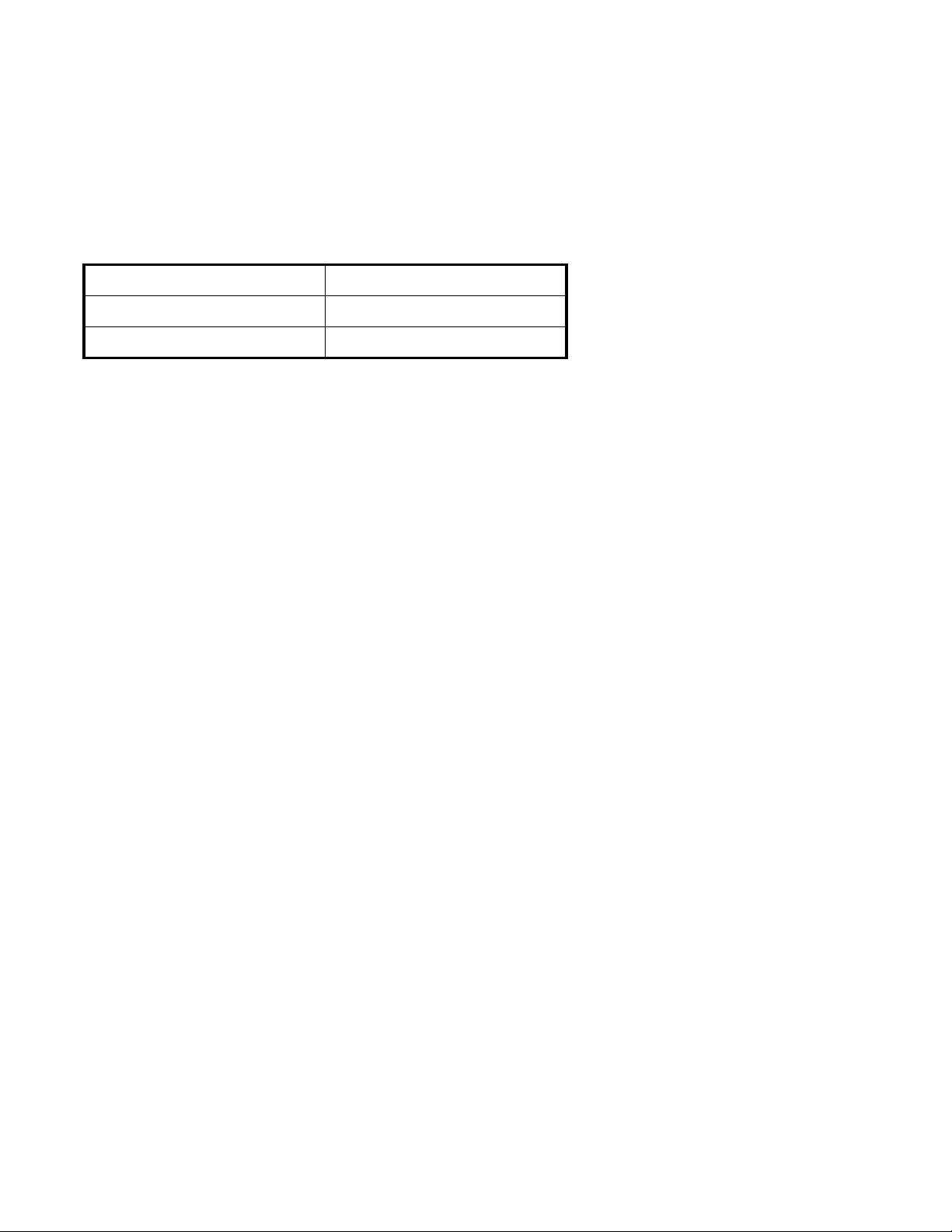
Table 1: Product ID table
Product ID Description
HUS154545VLF400 450 GB, FC-AL
HUS154530VLF400 300 GB, FC-AL
Note: The specifications in this document are subject to change without notice.
For technical and ordering information, please visit our website at http://www.hitachigst.com.
1.2 Glossary
Word Meaning
BMS Background Media Scan
Kb Kilobit = 1000 bits
Mb Megabit = 1,000,000 bits
GB Gigabyte = 1,000,000,000 bits
HDD Hard Disk Drive
MB Megabyte = 1,000,000 bytes
KB Kilobyte = 1000 bytes
PFA Predictive Failure Analysis
S.M.A.R.T. Self-Monitoring and Reporting Technology
FC-AL Fibre Channel - Arbitrated Loop
1.3 Caution
This drive can be damaged by ESD (Electric Static Discharge). Any damages incurred to the drive after its removal from the
shipping package and the ESD protective bag are the responsibility of the user.
Hitachi Ultrastar 15K450 (FC-AL) Hard Disk Drive Specification
1

Hitachi Ultrastar 15K450 (FC-AL) Hard Disk Drive Specification
2

2.0 Outline of the Drive
• Storage capacities of 450 GB, 300 GB
• Dual 4.250/2.1250/1.0625 Gb/s Fibre Channel Arbitrated Loop-2 host interfaces
• Supports dual-ported operations
• Supports full duplex operations
• Login BB_Credit=0
• Enclosure Service Interface (ESI, SFF-8045 Rev. 4.2) and Enclosure Initiated ESI (SFF-8067 Rev. 2.6) compliant
• Variable Sector Size (512,520,528 bytes/ sector)
• Tagged Command Queuing support
• Automatic read/write data transfer
• 3.6 ms seek time in read operation for 450 GB
• 3.6 ms seek time in read operation for 300 GB
• Adaptive read ahead algorithm
• Write Cache
• Back to back write
• ECC On The Fly correction
• Automatic defect reallocation
• Self diagnostics at power on
• Closed loop actuator servo
• Non head disk contact start/stop
• 15,000 RPM spindle rotation speed
• Automatic actuator lock
• PFA (S.M.A.R.T.)
• ANSI T10 Protection Information (End-to-End)
Hitachi Ultrastar 15K450 (FC-AL) Hard Disk Drive Specification
3

Hitachi Ultrastar 15K450 (FC-AL) Hard Disk Drive Specification
4

3.0 Fixed-disk Subsystem Description
3.1 Control Electronics
The drive is electronically controlled by a microprocessor, logic modules, digital/analog modules and various drivers and
receivers. The control electronics perform the following major functions:
• Perform self-checkout (diagnostics)
• Conduct a power-up sequence and calibrate the servo.
• Monitor various timers for head settling, servo failure, etc.
• Analyze servo signals to provide closed-loop control. These include position error signal and estimated veloci ty.
• Control of the voice coil motor driver to align the actuator onto a desired position
• Monitor the actuator position and determine the target track for a seek operation.
• Constantly monitor error conditions of the servo and take corresponding action if an error occurs.
• Control starting, stopping, and rotating speed of the spindle.
• Control and interpretation of all interface signals between the host controller and the drive
• Control of read/write accessing of the disk media, including defect management and error recovery
3.2 Head Disk Assembly
The head/disk assembly (HDA) is assembled in a clean room environment and contains disks, a spindle motor, actuator assembly, and voice coil motor. Air is constantly circulated and filtered when the drive is operational. Venting of the HDA is accomplished via a breather filter.
The spindle is driven directly by a brushless, sensorless DC drive moto r. Dynamic braking is used to stop the spindle quickly.
3.3 Actuator
The read/write heads are mounted in the actuator. The actuator is a swing-arm assembly driven by a voice coil motor. A
closed-loop positioning servo controls the movement of the actuator. An embedded servo data pattern supplies feedback to the
positioning servo to keep the read/write heads centered over the desired track.
The actuator assembly is balanced to allow vertical or horizontal mounting without adjustment.
Heads are moved out from the disks (unloaded) to protect the disk data during shipping, moving, or storage. At power down,
the heads are automatically unloaded from over the disk area and the head actuator locking mechanism will secure the heads in
the unload position.
Hitachi Ultrastar 15K450 (FC-AL) Hard Disk Drive Specification
5

Hitachi Ultrastar 15K450 (FC-AL) Hard Disk Drive Specification
6
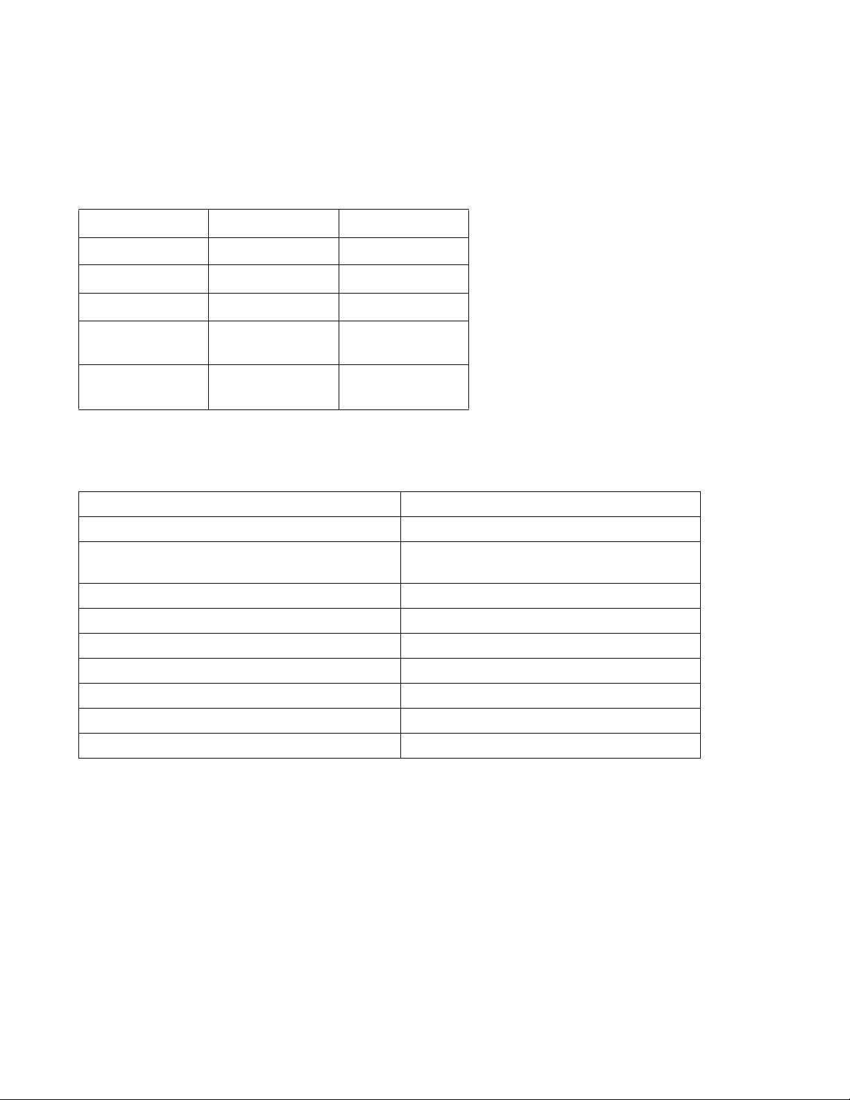
4.0 Drive Characteristics
4.1 Formatted Capacity
Table 2: Formatted Capacity
Description HUS154545VLF400 HUS154530VLF400
Label capacity 450 GB 300 GB
Number of heads 8 8
Number of disks 4 4
Total data bytes (512
bytes/sector)
Total logical data
blocks
450,098,159,616 300,000,000,000
879,097,968
(3465F870h)
585,937,500
(22ECB25Ch)
4.2 Data Sheet
Table 3: Data Sheet
Buffer to/from media 450 GB 1290 - 2120 [Mb/sec]
Buffer to/from media 300 GB 1265 - 1738 [Mb/sec]
Host to / from buffer (interface transfer rate) 106.25 MB/s (1 Gb/s) 212.5 MB/s (2 Gb/s)
425.0MB/s (4Gb/s)
Data buffer size 16MB
Number of buffer segments 1 - 254
Rotational speed 15,000 RPM
Recording density 1138 [Kbpi] (Max)
Track density 150,000 [TPI] (average)
Areal density 183 [Gb/sq. in.]
Data zones 23 Zones for 450 GB, 18 Zones for 300 GB.
Hitachi Ultrastar 15K450 (FC-AL) Hard Disk Drive Specification
7
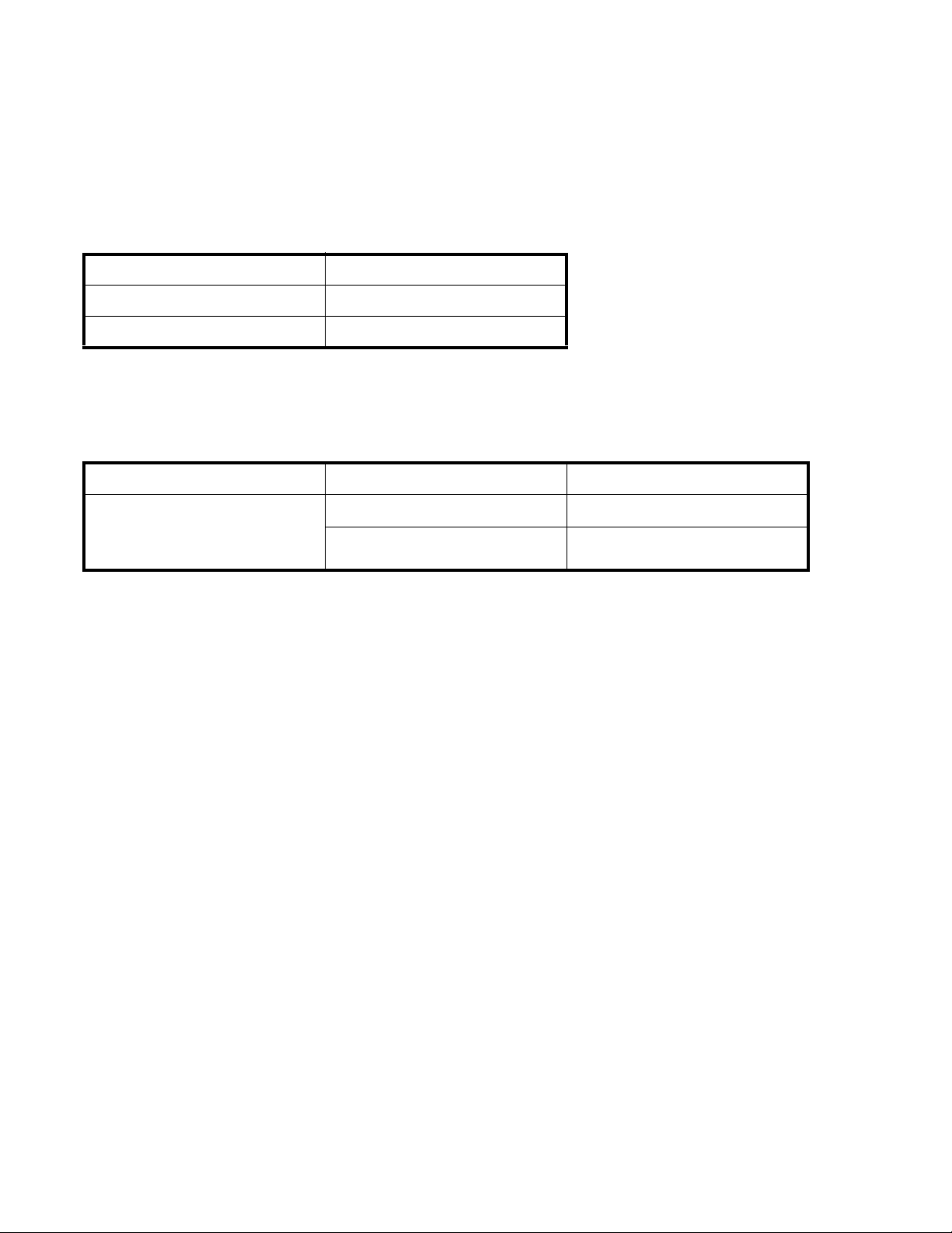
4.3 Inquiry Information
4.3.1 Product ID
Product ID in Section 19.5.1.1, “Inquiry Data Format - EVPD = 0, Page Code = 0” on page 126, is as follows:
Table 4: Product ID in Inquiry Command
Product ID Description
HUS154545VLF400 450 GB, FC-AL
HUS154530VLF400 300 GB, FC-AL
4.3.2 World Wide ID - Block Assignment
Block Assignment of World Wide ID is as follows:
Tabl e 5: Block assignment of World Wide ID in INQUIRY Command
Manufacturing Site Product Block Assignment
HUS154545VLF400
Singapore
Note (1) - Additional block assignment wi ll be issued as needed based on actual production volume.
HUS154530VLF400
001h
001h
(1)
(1)
Hitachi Ultrastar 15K450 (FC-AL) Hard Disk Drive Specification
8

4.4 Cylinder allocation
Zone Sectors /Tracks Cylinder/Zo ne
Start
Cylinder
End
Cylinder
0 1416 3600 0 3599
1 1404 3700 3600 7299
2 1395 700 7300 7999
3 1350 26500 8000 34499
4 1296 3900 34500 38399
5 1282 3300 38400 41699
6 1260 6900 41700 48599
7 1242 2100 48600 50699
8 1215 5100 50700 55799
9 1188 2400 55800 58199
10 1170 3200 58200 61399
11 1147 2200 61400 63599
12 1134 2400 63600 65999
13 1125 600 66000 66599
14 1080 8500 66600 75099
15 1026 3400 75100 78499
16 1012 2300 78500 80799
17 990 2900 80800 83699
18 972 1900 83700 85599
19 945 3900 85600 89499
20 918 2300 89500 91799
21 900 2900 91800 94699
22 877 500 94700 95199
User Cy lind e r Allocatio n 450 G B
Table 6: Cylinder allocation
Hitachi Ultrastar 15K450 (FC-AL) Hard Disk Drive Specification
9

Note: Values shown are nominal. Actual values will vary based on manufacturing optimization. Mode Page 03 (Format
Z o n e Secto rs /Tra cks Cylinder/Zo n e
Start
Cylinder
End
Cylinder
0 1188 5800 0 5799
1 1170 13300 5800 19099
2 1147 6400 19100 254 99
3 1134 3000 25500 284 99
4 1125 1200 28500 296 99
5 1080 13800 29700 43499
6 1041 800 43500 44299
7 1035 1800 44300 46099
8 1026 1900 46100 47999
9 1012 2700 48000 50699
10 1002 600 50700 51299
11 990 3100 51300 54399
12 972 2200 54400 56599
13 945 4600 56600 61199
14 918 2600 61200 63799
15 900 3300 63800 67099
16 877 2500 67100 69599
17 864 200 69600 69799
User Cylinder Alloca tion 300 GB
Device Parameters), page 180 and Mode Page 0C (Notch Parameters), page 188 provide methods to determine actual
medium format and zone parameters for specific drives.
4.5 Performance characteristics
Drive performance is characterized by the following parameters:
•Command overhead
•Mechanical head positioning
- Seek time
•Data transfer speed
•Buffering operation (read ahead/write cache)
Note: All the above parameters contribute to drive performance. There are other parameters that contribute to the performance of the actual system. This specification tries to define the bare drive characteristics, not system throughput, which
depends on the system and the application.
- Latency
Hitachi Ultrastar 15K450 (FC-AL) Hard Disk Drive Specification
10

4.5.1 Mechanical positioning
max 1 n–+ ) Tnin Tnout+(⋅()=
n 1=
Max
∑
max 1+()max()⋅
------------------------------------------------------------------------------------------------
4.5.1.1 Average seek time (including settling)
Table 7: Mechanical positioning performance
Model Command Typical (ms) Max
450 GB Read 3.3 5.0
Write 3.8 5.4
300 GB Read 3.1 4.5
Write 3.6 5.1
“Typical” and “Max” are used throughout this document and are defined as follows:
Typical Average of the drive population tested at nominal environmental and volt age conditions.
Max Maximum value measured on any one drive over the full range of the environmental and voltage conditions.
(See Section 8.0, “Environment” on page 25 and Section 9.0, “DC Power Requirements” on page 29 for
ranges.)
Seek time is measured from the start of the actuator’s motion to the start of a read or write operation. Average seek time is
measured as the weighted average of all possible seek combinations.
Weighted average =
Where:
max = Maximum seek length
n= Seek length (1 to max)
Tn.in = Inward measured seek time for an n track seek
Tn.out = Outward measured seek time for an n track seek
Hitachi Ultrastar 15K450 (FC-AL) Hard Disk Drive Specification
11
4.5.1.2 Full stroke seek time
Model Command Typical (ms) Max
450 GB Read 6.2 11.1
Write 7.1 11.5
300 GB Read 5.8 9.4
Write 6.4 10.1
Full stroke seek is measured as the average of 1,000 full stroke seeks with a random head switch from both directions (inward
and outward).
4.5.1.3 Average latency
Table 8: Latency time
Rotation Time for a revolution (ms) Average latency (ms)
15,000 RPM 4.0 2.0
Hitachi Ultrastar 15K450 (FC-AL) Hard Disk Drive Specification
12

4.5.2 Drive ready time
Table 9: Drive ready time
Model Typical (sec) Maximum (sec)
450 GB Model 21.0 29.9
300 GB Model 21.0 29.9
4.5.3 Spindle stop time
Table 10: Spindle stop time
Model Typical (sec) Maximum (sec)
450 GB Model 11.0 20
300 GB Model 11.0 20
The period from power off to the complete stop of the rotating spindle is categorized as 'operating'. The Operating shock criteria apply during this period. Refer to section 12.3, “Operating shock” on page 41.
4.5.4 Data transfer speed
Table 11: Data transfer speed (sector size 512 Byte case)
Description
Disk-buffer transfer
Instantaneous 0 450 GB 179.7 179.7
Measured typical values for sustained diskbuffer tranfer rate
Instantaneous 22 450 GB 112.3 112.3
Measured typical values for sustained diskbuffer tranfer rate
Notes:
• Instantaneous disk-buffer transfer rate is derived by: (Number of sectors on a track) x 512 x (revolutions/sec)
• For this table, '1 MB / Sec' should be interpreted as 1,000,000 bytes per Second.
• The number of sectors per track will vary by zone because of the linear density recording.
• Sustained disk-buffer transfer rate is the average rate measured while transferring multiple cylinders of data. It differs from the instantaneous transfer rate because of the time required to change tracks (Cylinder skew and Head
skew). In addition, time is added for the occasional missed transfer.
Zone Model Read Write
0 300 GB 152.1 152.1
0 450 GB 160.0 155.8
0 300 GB 135.0 131.5
17 300 GB 110.6 110.6
22 450 GB 99.9 97.3
17 300 GB 98.2 95.6
Typical (MB / Sec)
4.5.5 Buffering operation (read ahead/write cache)
This hard disk drive has a buffer for read ahead (see Segmented Caching, page 331).
Hitachi Ultrastar 15K450 (FC-AL) Hard Disk Drive Specification
13

Hitachi Ultrastar 15K450 (FC-AL) Hard Disk Drive Specification
14
 Loading...