

Page 1
No.
347 EGF
HT-t55
.
l,vtr I Ett I D. iltt-rALr' Dr.rrvilYrArrrE
CONTENTS
SPECIFICATIONS'
CARACTÉRTSTTOUE TECHN1OUES..................
FEATURES.
SERVICE
POINTS D'ENTRETIEN.
ADJUSTMENT
BLOCK DIAGRAM
scHEM4.........
REPLACEMENT
TABLEAU
PRINTEO WIBING
PLAN DE 8ASE................
CIRCUIT
EXPLODED VIEW
DARSTELTUNG.VUEÉCLATÉE
DESCRIPTION
DER NEUEN KOMPONENT.DESCRIPTION DE
NOUVELLE COMPOSANT..........
INHALT' SOMMAIRE
TECHNISCHE DATEN,
BESONDERHEITEN. CARACTÉNISIOUCS.... T, Z
.
POINTS
DIAGRAM.SCHATTPI.AN
WARTUNGSPUNKTE.
.
EINSTELLUNGEN
.BLOCK
SCHEMA.
PARTS LIST' ERSATZTEITLISTE
DES PIECES....
BOARD ' PRINTPI.ATTEN
.
AUSEINANDERGEZOGENE
OF THE NEW COMPONENT'
.
RÉGI.AGE. .................... 6,
..........................
.
.....
.
................................. I 1
.PLAN
DE CIRCUIT..... 12
........................î3,14
BASCHREIBUNG.
I-A
.....
9,
1,2
7
I
îO, 15
,^\
SAFETY PRECAUTION
The following
1.
Since
parts.
Critical
2. Betore returning a repaired unit to the
it is
precautions
parts
many
Especially
parts
critical
are marked with A in the
completely safe
should
the unit have
in
parts
to
operate
in the
SPECIFICATIONS
Type
Platter
Motor
Speed
Speed
change system
s/N
Wow
and flutter
Speed deviation
Speed drift
(for
timel
temperaturel
lfor
Tonearm
Effective length 95 mm
Tracking error +0.1"
Lead wire capacitanca 140
quartz
2-speed
automatic
Aluminum alloy dre-cast, 296 mm
diameter
Brushless, Slotless, Coreless DC
"Unitorque"
2-speeds;33-1/3 and 45 rpm
Electronic
78 dB
0.025%
oo03%
O OO37olhour
o.0o3%
Linear tracking tonearm
turntable
change-over system
(DrN-B)
(wRMS)
(5
-
pF
be observed
special safety
power
circuit diagram.
customer,
without
motor
35'C)
danger
controlled
when
servicing.
related characteristics,
circuit block should
the service
of electrical shock.
direct
drive fully
outer
servo
always use
genuine
not be replaced with other makers.
technician must
Cartridge
Frequency
Output voltage
Channel difference
Channel s€paration
Tracking force
Weight
Stylus tip
Power source
Power consumption
Dimensions
Weight
thoroughly
fesponse
Dual magnet type
10
25,000 Hz
-
3.5 mV at 1 kHz,
ldBatlkHz
23 dB aî
+0259
1.25
59s
Diamond stylus
'I
20V 60 Hz for U S A and Canada
22OV 50
240V 50 Hz for U K
11O-12O/22O-240V 50/60 Hz forAsian
Latin American countries
15 watts
(W)x83 (H)x
315
45ks(1Olbs)
Hitachi's
replacement
the unit to ascertain
(MT-33)
mm/sec.
50
1 kHz
(DS-ST33)
Hz for
Europe standard
Australia
and
(D)
31 5
mm
that
sîandard
standard
and
1
Low-mass,
2.
Disk
3.
Slimly
dynamic balance linear tracking
jacket
size
designed
SPECIFICATIONS AND PARTS
DIRECT
October
for
easy
installation
Unitorque motor
DRIVE
î
982
tonearm
anywhere
4.
5.
6.
ARE SU&'ECT
AUTÍIMATIC
TOYOKAWAWORKS
play
(quartz
from
any
any
lock PLL
position
position
Ouartz control
Repeat
Timer staÉ from
TO
CHANGE FOR IMPROVEMENT.
TURNTABLE
servol
on disk
the
on
{program
Cisk
repeat)
Page 2
HITACHI HT-L55
SICH ERH EITSMASSNAH M
Bei Warîungsarbeiten
1. Da verschiedeneTeile
Netzterl
sollten nicht durch àhnliche
gekennzeichnet
A
Vor
Auslieferung
der
terziehen,
TECHNISCHE
Tvp
Plattenteller
Motor
Drehzahlen
Drehzahl-Unschaltung
Fremdspannungsanstand
Gleichlauf
Drehzahlabweichung
Zeitdrift der Drehzahl
Temperaturdrift der Drehzahl
Tonealm
Effektive Lànge
Tangentialer Spurfehlwinkel
Leitu ngsdrahtkapazitàt
Tonabnehmer
um sicherzus.tellen, daB sicherer Betrieb
DATEN
schwankungen
folgenden
die
sind
dieses Geràtes Sicherheitsfunktionen
reparierten
eìnes
Vollauîomalischer,
îantriebs-Plattenspieler mit 2 Geschwin-
d igkeiten
Aluminum-DruckguRlegiergierung,
durch messer 296
Bùrsten-.
Schlitz-,
Gleichstrom-"Unitorque"
33-1/3 und
Elektronìsches Umschalsystem
(DrN-B)
78
dB
(wRMS)
o,025%
0,o03%
0.003%/std
(5
0,003%
Linear abtastender
95
+0,1'
140
Doppelmagnettyp
-
mm
pF
MARKMALE
1
Massearmer,
Rillenfùhrung
2
Abmessungen von
hen bequeme Aufstellung ùberall
3
,,Unitorque"
4
Kristallsteuerung
dynamisch balancierter Tonarm mit
der GróBe
Motor
-
in flachern Design
(q
uartzgesteuerte P LL-Servoschaltungl
einer
EN
SicherheitsmaBnahmeh
Teile
anderer Herstellèr
Geràtes an den Kunden muB der Wartungstechniker das Geràt
ohne die
quarzgesleurîer
mm
kernloser
U/min
Servomotor
fonarm
(lMT-33)
45
35"C)
linearer
Plattenhúlle
ermóglic-
zu beachten:
aufweisen, nur Original-Hirachi-Ersatzteile
werden Alle krrtischen Teile sind im Schaltplan mit
ersetzt
von elektrischen Schlàgen
Gefahr
Direk-
AuBen
Freguenzgang
Ausgangsspannung
Unterschied des
Ubertragungsmatses
Kanaltrennung
Auflagekraft
Gewicht
Abtastnabel
Stromversorgung
Leistungaufnahme
Abmessungen
Gewicht
Kontaktfreier, automatischer
5.
durchmesser und
Wiederholtes Abspielen von
6.
Schallplatte
Schaltuhrstart
7.
von
-drehzahl
ieder
verweóden Kritische
grúndlìchen
gewàhrleistet
einer
isl
10-25000H2
mV bei 1 kHz,
3,5
1
bei 1 kHz
dB
23 dB bei
1.25
5,9s
Diamantnabel
1 20Vl60 Hz
22OV/5O Hz
24OVl5O
lralien-Norm)
11O-12O122O-240V 50/60 Hz
und
'l
315
4,5 ks
beliebigen
'1
kHz
+0.259
(DS-ST33)
(fúr
(ftir
(fùr
Hz
lateinamericanische
Watt
5
jeder
(H)x
(B)
x 83
Detektor
von Schallplatten-
beliebigen Stelle der
Stelle der
Teile im
dem Symbol
Prùfung un-
mm/sec
50
-und
U S.A
Europa-Norm)
GroBbritannien und Aus-
315
Kanada-Norm)
Lànder)
(T)
mm
(fùr
Asien
Schallplatte
+
PRÉCAUTIONS
précautions
Les
1 Etant
des
pièces
suivanîes doivent ètre observées
que
donné
rechange
de
d'alimentation
du symbole A dans le
2 Avant de retourner l'appareil ré7aré au
danger
de chocs électriques
DE
nombreux
de
qui
ne
doivent en aucun
schéma
SÉCURITÉ
composants de l'appareil
d'origine
Hitachi
cas
de montage
client, le technicien
chaque
pour
ètre
effectuer un
remplacées par
CARACTÉN ISTIOU E TECH N IOU ES
Type
Plateau
Moteur
Vitesses
Système
de vitesses
Signal/Bruit
Pleurage et
Variation
Modification de la vitesse
Bras de lecture
de changement
scintillement
vitesse
de la
(En
fonction du temps|
lonction de la tempéra-
{En
ture!
Longueur
Erreur
de
réelle
piste
Platine
à automatisme
entraînement direct, contrólée
Alliage alumrnium
diamètre extérieur
balai, fente ni noyau; moleur
Sans
ple
2 vitesses:33-1/3
Changement
que
78
o,o25%
o,o03%
O,O037o
0,OO3%
Bras a
95 mm
+0.1'
unique"
(DrN-B)
dB
(wRMS)
par
(enîre
lecture linéaire
à servo CC
heure
intégral,
fonte,296
et
45
et
trlmn
par
commutation électroni-
5
35'C)
et
fois
2 vitesses,
par quartz
mm
de
"cou-
a
qu'une
reparation
possèdent
des
remplacement
celles d'autres
procéder
dort
Cellule
Alimentation
Consommation
Dimensions
Poids
ètre faite
doit
caractéristiques
Cecr
rapporte noîamment aux
se
fabricants Les
un essar
a
Capacité de conducteur
Réponse en fréquence
Puissance
Différence
Séparation de canal
Force d'appui
Poids
Pointe de lscîure
complet
sortie
de
de canal
de courant
relatives à la sécurité, utiliser uniquement
pièces
Hz
Hz
qu'il
pour
pour
pour
{H)
x
critiques du bloc
présente
ne
(MT-33)
(DS-ST33)
normes
les
les normes
les
normes
américaines
euro-
britanniques
50/60 Hz
(P)
mm
31 5
aucun
pour
pièces
critiques sont accompagnées
pour
s'assurer
140pF
Type à mobiles aimants
1O-25O00H2
3.5 mV é 1 kHz,50 mm/sec
ldBalkHz
23dBà1kHz
+0.259
1.25
5,9s
Pointe de lecture en diamant
12OV
160
et canadiennes
22OV
/5O
péennes
24OV/5O Hz
et les normes australiennes
1 1O-12O/22O-240V,
pays
d'Asie et d'Amérique Latrne
15W
(L)x
315
83
4.5 ks
^.
lès
cARACTÉnrSrrOUeS
1 . Bras
2.
3.
4-
de lecture linéaire
masse
Dimensions
d'une
pochette
d'installation
Moteur a couple
unique
Circuit d'asservisèement
a équilibre dynamique
de
de
pour
de disque
grande
constrùc,tion simple
phase par quartz
et faible
facilité
Détecteur
5.
sans contact
6.
7.
automatiqúe de dimension/vitesse
point
quer
grarnmdeuy
disque
de
du disque
a.rpaÉir
Page 3
HITACHI
HT-155
SERVICE
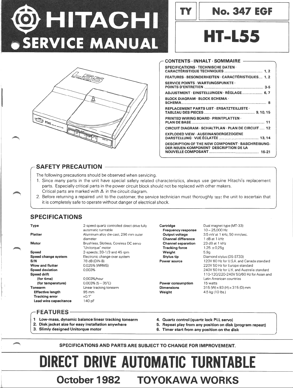
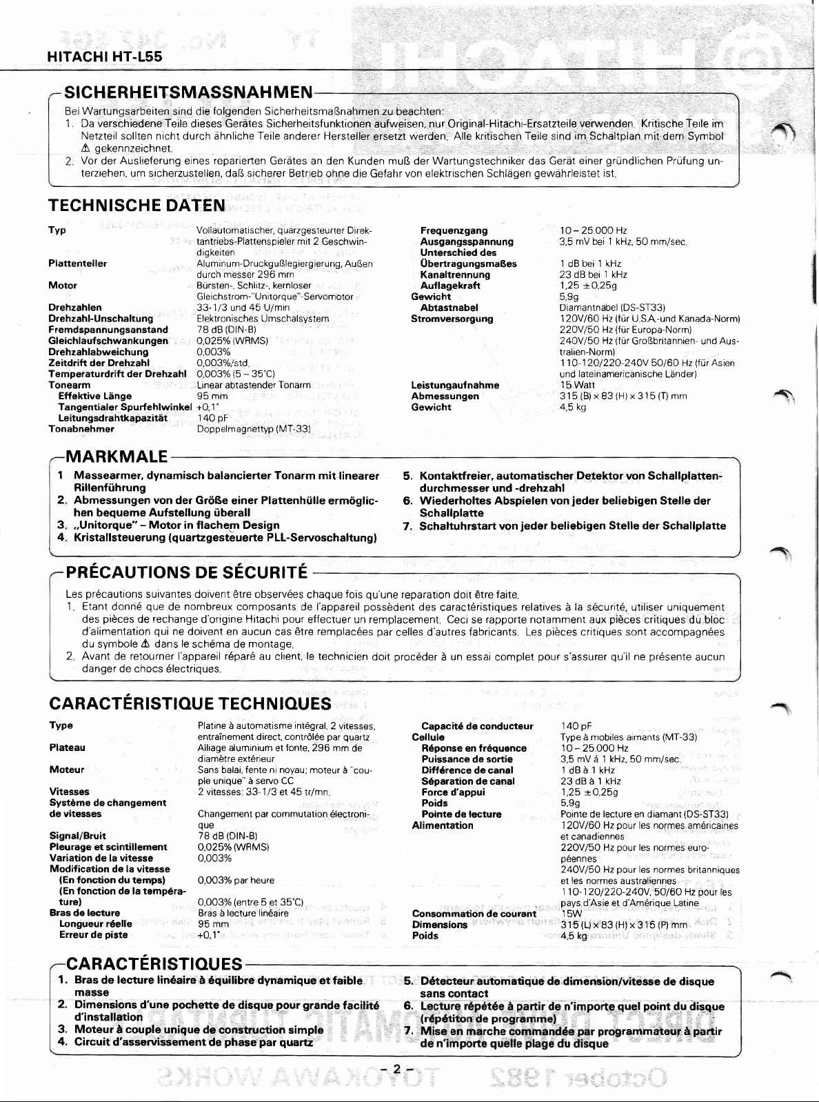
1. Removing Control PWB
Remove 6 screws
Next,
2. Removing
After removing bottom
screw)
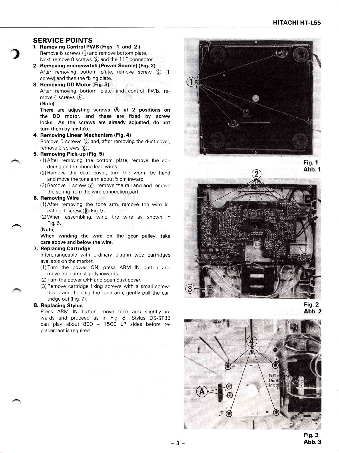
3. Removing
After
move 4 screws
(Note)
There are adjusting
the DD
POINTS
(Figs.
1
and 2
and remove bottom
remove
and then the fìxing
removing bottom
motor, and these are fixed by
@
8 screws
microswitch
DD Motor
(Fig.3)
@
screws
the 1 1 P connector
@and
(Power
plate,
plate.
plate
@
Source)
remove
and control PWB,
at 2
I
plate
(Fig.
screw
positions
locks. As the screws are already adjusted, do
them by mistake.
turn
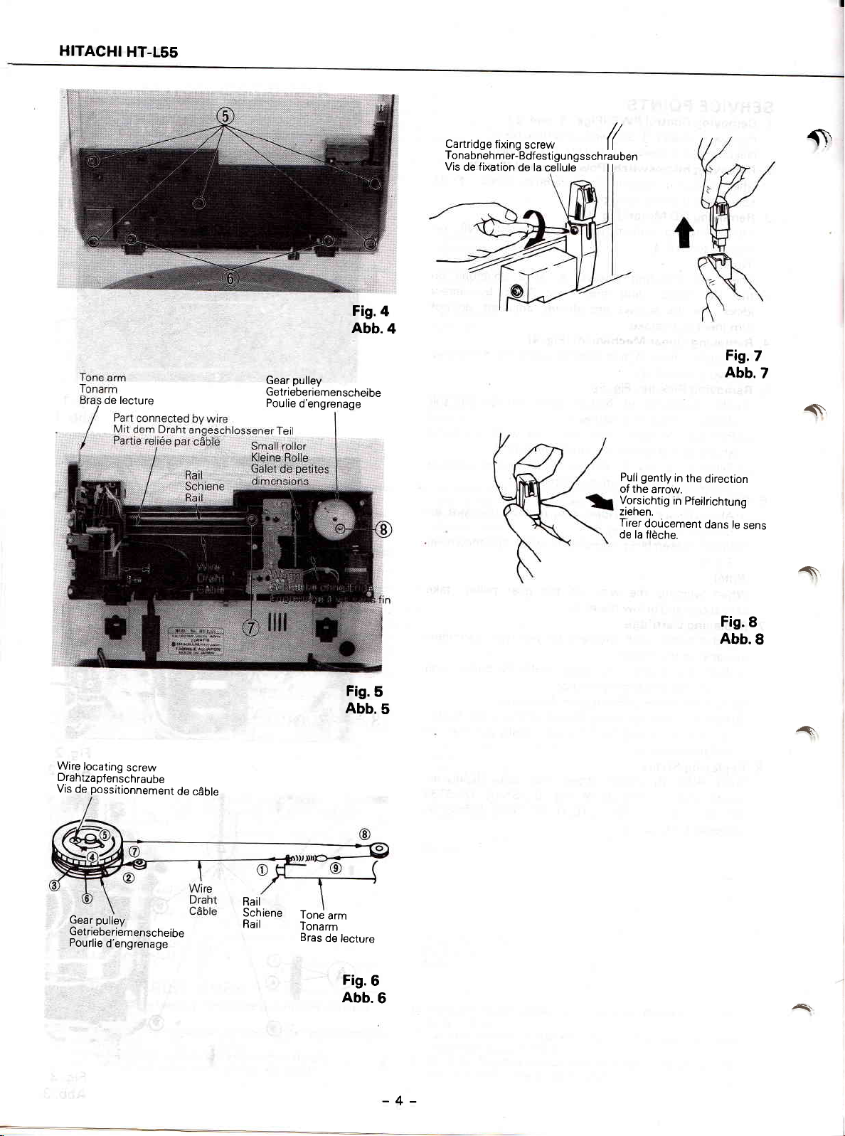
4. Removing
Remove 5 screws @ and,
remove 2 screws
5. Removing
(1)After
dering on the
(2)
Remove
and move the
(3)
Remove 1
the
Removing Wire
6.
(1)After
cating
(2)
When assembling, wind the
Fig. 6.
(Note)
Linear Mechanism
@.
Pick-up
removing the bottom
(Fig.5)
phono
the dust cover,
arm about 5
tone
screw
@,
spring from
removing the tone arm,
1 screw
the wire
@(Fig.5).
When winding the wire on
care above and below the
lead wires
(Fig.
a)
after removing the
plate,
remove
turn the worm
inward.
cm
remove the rail and
connection
wire.
part.
remove
wire
gear pulley,
the
as shown in
and remove
the wire lo-
7. Replacing Cartridge
lnterchangeable
available
(1
(2)Turn
(3)
on
the
)Turn
tone
move
the
Remove cartridge fixing screws with
driver and, holding
tridge out
8. Replacing
Press ARM lN button, move
wards
can
placement
and
play
with ordinary
the
market.
power
arm slightly inwards.
power
(Fig.
Stylus
proceed
about 8OO
is required.
ON,
OFF and open dust
the
7)
as
-
plug-in
press
ARM
tone
arm,
tone arm
in Fig
1 500 LP
type
lN
cover.
a small
gently
pull
8. Stylus
sides before re-
2)
(1
@
re-
on
screw
not
dust cover,
the sol-
by hand
take
cartridges
button and
screw-
the
car-
slightly in-
DS-ST33
Flg.2
Abb.2
-3-
Fis.3
Abb.3
Page 4
HITACHI
HT-155
de lecture
pulley
Gear
Getriebe
Poulie
riem
en
d'engrenage
s cheibe
Fig.4
Abb.4
cartridge
Tonabnehmer-Bdfestigungsschrauben
Vis
fixing
de fixation
screw
de la
cellule
(
ll
gently
Pull
of the
arrow.
Vorsichtig
ztehen.
Tirer
doúcement
de la flèche.
Fis.7
Abb.7
in
the
direction
in Pfeilrichtung
dans
le
{\,
.s.
sens
Wire
locatino
Drahtzapfenich
Vis
de
Gear
Getrieberiemenscheibe
Pourlie
screw
possitionnement
raube
pulley
d'engrenage
de
c6ble
Rail
Sch ene
Rail
Tone
Tonarm
Bras
de
arm
lecture
Fig.6
Abb.6
A.
Fis.8
Abb.8
Fig.5
Abb.5
^'
At
-4-
Page 5
HITACHI
HT.L55
/r\
,-\
/a\
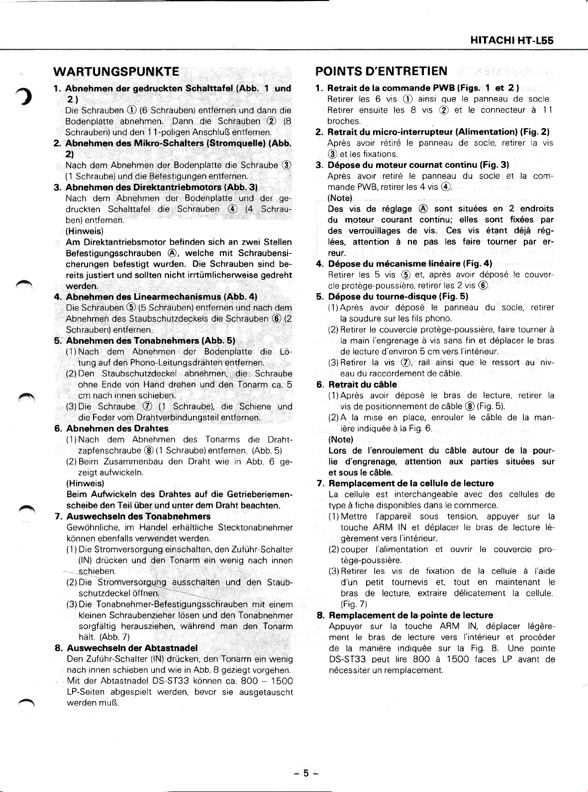
WARTUNGSPUNKTE
1. Abnehmen
gedruckten
der
Schalttafel
(Abb.
2l
Die
Schrauben
Bodenplatte abnehmen.
Schrauben)
2. Abnehmen des
(6
Schrauben)
O
und
1 1-poligen AnschluB entfernen.
den
Mikro-Schalters
2l
Nach dem Abnehmen der
(1
Schraube)
3. Abnehmen
Nach dem Abnehmen
druckten Sehalttafel
ben) entfernen.
(Hinweis)
und die Befestigungen
des Direktantriebmotors
der Bodenplatte und
die Schrauben
Am Direktantriebsmotor
Befestigungsschrauben
cherungen
reits
werden.
4. Abnehmen des
Die Schrauben
Abnehmen
Schrauben)
Abnehmen des Tonabnehmers
5.
(1
Nach dem Abnehmen der
)
tung auf den
(2)
Den
ohne Ende von Hand drehen und den Tonarm
cm
(3)Die
die
6. Abnehmen des
(1
Nach
)
zapfenschrauOe
(2)
Beim Zusammenbau den
zeigt aufwickeln.
(Hinweis)
Beim Aufwickeln des Drahtes auf
scheibe
befestigt wurden.
justiert
und sollten nicht
Linearmechanismus
€)
des Staubschutzdeckels die Schrauben
entfernen
Phono-Leitungsdràhten
Staubschutzdeckel
innen
nach
SchrauOe
Feder vom Drahtverbindungsteil entfernen.
Drahtes
Abnehmen des
dem
den Teil úber und unter dem Draht beachten.
@,
(5
Schrauben)
schieben
(1
@
(t
Schraube) entfernen
@
7. Auswechseln des Tonabnehmers
Gewòhnliche, im Handel erhaltliche Stecktonabnehmer
kónnen
(1
(2)
(3)Die
ebenfalls
je
D
Stromversorgung einschalten, den Zufùhr-Schalter
)
(lN)
drùcken und den
s-chieben.
Die
Stromwersor€Lu-Qg
schutzdeckel óffnen.
Tonabnehmer-Befestigungsschrauben mit
kleinen Schraubenzieher
sorgfaltig
(Abb.
hiirt.
veruvendet werden.
herausziehen, wàhrend man
7)
8. Auswechseln der Abtastnadel
Den Zufúhr-Schalter
nach innen schieben und wie in Abb. 8
(lN)
drticken, den
Mit der Abtastnadel DS-ST33 kónnen
LP-Seiten abgespielt werden, bevor
werden muB.
entfernen und
Dann die Schr:auben
(Stromquelle) (Abb.
Bodenplatte die
entfernen.
(Abb.
Schraube
3l
@ t+
befinden sich an zwei
welche mit Schraubensi-
Die
Schrauben sind be-
irrtùmlicherweise
(Abb.4)
entfernen und
(Abb.
5)
Bodenplatte
entfernen.
abnehmen,
Schraube), die Schiene
Tonarms
Draht wie
Tonarm
ausschaltén und
ein
lósen
und den Tonabnehmer
die Schraube
die Draht-
(Abb.
in Abb
die
Getrieberiemen-
wenig
nach innen
den Staub-
den Tonarm
Tonarm
geziegt
sie ausgetauscht
vorgehen
ca. 800
1
und
dann die
@
@
ge-
der
Schrau-
Stellen
gedreht
nach dem
@
die Ló-
ca. 5
und
5)
ge-
6
einem
ein wenig
1500
-
POINTS
1. Retrait de la commande
Retirer les 6
Retirer ensuite
(8
broches.
2. Retrait du micro-interrupteur
Apres
@
Dépose du moteur cournat
3.
Après avoir
mande PWB, retirer les
(Note)
Des vis de
du moteur courant
des
lées, attention à
reur.
4. Dépose du mécanisme
Retirer
cle
5. Dépose du
(1)Après
(2
(2)
(3)
6. Retrait
(1
(2)A
(Note)
Lors
lie
et sous
D'ENTRETIEN
PWB
vis
O
les 8
le
rétìré
avoir
fixations.
et les
retiré le
réglage
verrouillages
de vis. Ces
ne
les 5 vis @ et, apres
protège-poussière,
tourne-disque
avoir déposé
la
soudure
Retirer le couvercle
la main l'engrenage à
lecture d'environ 5 cm vers l'intérteur.
de
Retirer la vis
raccordement de càble.
eau du
du
càble
positionnement
vis de
avoir déposé
)Après
la mise en
ière indiquée à la Fig. 6
l'enroulement du c6ble autour de la
de
d'engrenage,
le
càble.
sur les
@,
fils
place,
attention
que
ainsi
vis
@
et
(Alimentation) (Fig.
panneau
continu
panneau
4 vis
@.
sont situées en 2 endroits
@
continu; elles sont
pas
les faire
linéaire
avoir déposé le
retirer les 2 vis
(Fig.
panneau
le
phono.
protege-poussière,
vis
sans
rail
ainsi
le
bras de
de c6ble
enrouler
aux
(Figs.
1 et 2
panneau
Ie
le
connecteur à
(Fig.
retirer la vis
3l
de socle,
du socle
vis
étant déjà
tourner
(Fig.
a)
@
5)
du socle, retirer
faire tourner
fin
et déplacer le bras
que
le ressort
lecture,
(Fig.
@
5).
le
càble de la man-
parties
)
de socle.
'l 'l
2)
et la
com-
fixées
par
rég-
par
couver-
niv-
au
er-
retirer la
pour-
situées sur
à
7. Remplacement de la cellule de lecture
La cellule est
type à fiche disponibles dans
(1
Mettre l'appareil sous
)
touche ARM lN et déplacer
gèrement
(2)
couper
tège-poussière.
(3)
Retirer les vis de
d'un
bras de
(Fig.
7)
Remplacement de lagointe de lecture
8.
Appuyer sur
ment le bras de lecture
de la manière
DS-ST33
nécessiter
interchangeable avec des
le
commerce.
tension,
le bras
vers
I'intérieur.
l'alimentation
petit
tournevis et,
lecture, extraire délicatement la
et ouvrir le
fixation
de
tout
la
en
la touche ARM lN, déplacer
vers l'intérieur
indiquée
peut
lire 800 à
remplacement
un
sur la
Fig
1500 faces
cellules de
appuyer sur
lecture lé-
de
couvercle
pro-
cellule à l'aide
maintenant le
cellule.
légère-
procéder
et
8. Une
pointe
LP avant de
la
-5-
Page 6
HITACHI HT-155
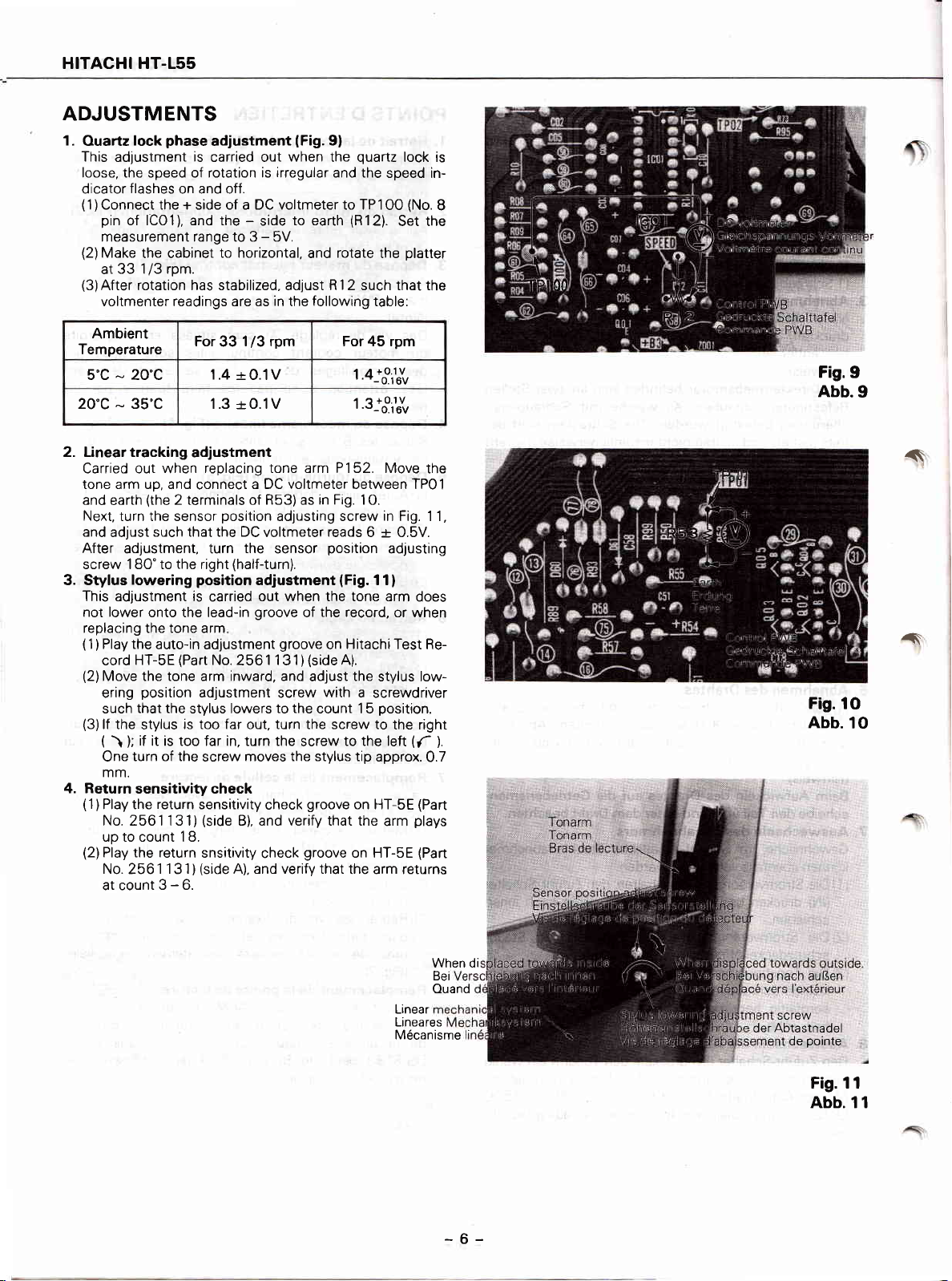
ADJUSTMENTS
1.
Ouartz
This
adlustment
loose, the speed of rotation is
dìcator
(
1
Connect the + side of a DC voltmeter to TP 1
)
pin
measurement range to 3
(2)
Make
33 1/3 rpm.
at
(3)After
voltmenter readings are as
phase
lock
flashes
of lCOl), and the
the cabinet
rotation has stabilized. adjust R
adjustment
is
carried out
on and off.
to horizontal,
-
irregular
side
5V.
-
in
when
to earth
the
lFig.
and
following
9l
quartz
the
and the
speed in-
O0
(R12).
rotate
the
1
2 such that the
table:
lock is
(No.
Set the
platter
8
Ambient
Temperature
5'C - 20'C
20'c
35'C 1.3
-
2. Linear tracking
Carried out when
tone arm up, and
and
Next, turn the sensor
and
After
screw 180" to
3. Stylus
This adjustment is
not lower
replacing the tone arm
(1)
(2)
(3)
4. Return
(1)
(the
earth
adjust
adjustment, turn
lowering
Play the
HT-SE
cord
Move the tone arm inward, and
position
ering
that the
such
lf the
stylus
(
if
\ );
turn of the
One
mm.
sensitivity check
Play the
For33 1/3 rpm For 45 rpm
-rO.1V
1.4
+0.1V
adjustment
replacing tone arm P152. Move
connect
2 terminals of R53) as
such that the DC
the
right
position
onto the lead-in
auto-in adjustment
(Parr
adjustment
stylus lowers
is too far out, turn the screw to
a DC voltmeter between TPOl
position
adjusting screw
voltmeter
the
sensor
(half-turn).
adjustment
carried
out when the tone arm
groove
groove
No.
2561131
screw
to the
it is îoo far in, turn the
moves the stylus tip
screw
return
sensitivity
check
No.2561131)(side B), and verify that the
up to count 1 8.
(2)
Play the return
No.
2561
1
31
snsitivity
(side
A), and verify that
)
check
atcount3-6.
in Fig.
reads
position
the record,
of
on
(side
)
adjust
with a
count 15
screw
groove
groove
t.+-.8ill
t.s--oîiluu
1O.
in
Fig. 11,
-r
6
0.5V.
adjusting
(Fig.
11)
or when
Hitachi
A).
to the left
Test Re-
the
stylus low-
screwdriver
position.
the right
(f
approx.
on HT-SE
on HT-SE
the arm returns
arm
plays
the
does
0.7
(Part
(Part
Fis.9
Abb.9
î
^'
Fis.lO
Abb.
10
).
<
When di
Bei
Ouand
Linear
Lineares
Mécanisme
-6-
SCTCW
der Abtastnadel
de
pointe
Fig. 11
Abb. î I
Page 7
HITACHI
HT-155
,^\
A\
//\
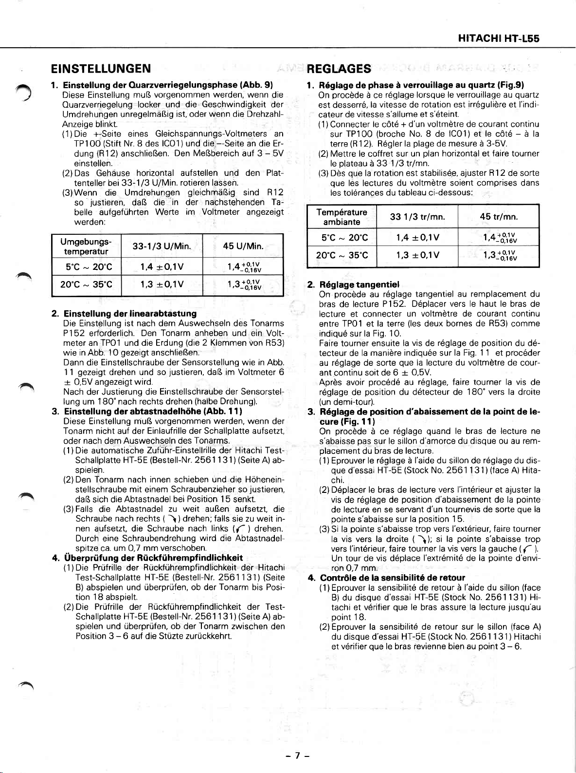
EINSTELLUNGEN
1. Einstellung
Diese Einstellung muB
Ouarzverriegelung
Umdrehungen
Anzeige blinkt.
(1
Die +-Seite eines
)
TP 1 00
dung
einstellen.
(2)
Das Gehàuse
tenteller
(3)Wenn
so
belle
werden:
Umgebungs-
temperatu!'
5'C
20'c
2.
Einstellung
Die Einstellung
P152
meter an TPOl und die Erdung
wie in Abb. 1O
Dann
gezeigt
1 1
-r
0,5V
Nach der Justierung die
lung um 180'nach rechts drehen
3. Einstellung
Diese Einstellung
Tonarm nicht auf der
oder
(1)
Die automatische
Schallplate
spielen.
(2)
Den Tonarm nach innen schieben und die Hóheneinstellschraube
daB sich die
(3)
Falls
Schraube
nen
Durch eine Schraubendrehung
spitze ca.
..
4. Uberprùfung der
(1)Die
Test-Schallplatte
B) abspielen und ùberprúfen,
tion
(2)Die
Schallplatte
spielen
Position 3
der
O.uarzverriegelungsphase
vorgenommen
locker und die-
ist, oder wenn die Drehzahl-
Gleichspannungs-Voltmeters an
lCO1
)
Den MeBbereich
(Stift
(R12)
unregelmiiBig
Nr. 8
des
anschlieBen.
horizontal aufstellen
die
in
rotieren lassen.
bei 33-1/3 U/Min.
die Umdrehungen
'
justieren,
daB
aufgefùhrten Werte
33-1/3 U/Min.
-+O.1V
20"C
-
35'C
-
erforderlich.
Einstellschraube der Sensorstellung wie in Abb.
die
drehen und so
angezeigt wird.
nach
dem
die
aufsetzt, die Schraube
1.4
-rO,îV
1,3
der linearabtastung
ist nach
Den Tonarm anheben und ein Volt-
gezeigt
der
abtastnadelhóhe
muB vorgenommen werden, wenn
Einlaufrille
Auswechseln des
Zufùhr-Einstellrille der Hitachi Test-
HT-5E
mit
einem
Abtastnadel bei
Abtastnadel zu
nach rechts
Auswechseln
dem
anschlieBen.
justieren,
Einstellschraube der Sensorstel-
(Bestell-Nr.
Schraubenzieher
weit
(
drehen;
ì
)
werden,
Geschwindigkeit
und die.--Seite an die Er-
und den Plat-
gleichmaBig
nachstehenden Ta-
der
im Voltmeter angezeigt
45 U/Min.
(die
2 Klemmen
daB irn Voltmeter 6
(halbe
Drehung).
(Abb.
Schallplatte aufsetzt,
der
Tonarms.
2561 1 31)
Position
nach links
15
auBen aufsetzt, die
falls
wird die Abtastnadel-
um
mm verschoben.
0,7
Riickfúhrempfindlichkeit
Prùfrille der
18
abspielt.
Prúfrille
und ùberprùfen, ob der Tonarm zwischen
Rùckfúhrempfindlichkeit
(Bestell-Nr.
HT-sE
ob der
Rùckfùhrempfindlichkeit der Test-
der
(Bestell-Nr.
HT-5E
6 auf die Stùzte zurùckkehrt.
-
2561 1 31
2561 131)
Tonarm
(Abb.
9)
wenn
auf 3
-
sind R12
1,4--3f&
1'3--8iluu
Tonarms
des
von R53)
11)
(Seite
A)
justieren,
so
senkt.
sie zu weit in-
(7.
drehen.
)
Hitachi
ddr
(Seite
bis Posi-
(Seite
A)
)
die
der
5V
der
ab-
ab-
den
REGLAGES
phase
1. Réglage
On
est desserré,
cateur
(1)Connecter
(2)
(3)
Température
ambiante
de
procède
sur
terre
Mettre
le
Dès
que
les
à ce
la
vitesse s'allume et s'éteint.
de
le
TP100
(R
1 2), Régler
le
coffret
plateau
à 33 1/3 trlmn.
que
la
les lectures
tolérances
5'C - 20'C
20"c
2.
On
35"C 1,3
-
Réglagetangentiel
bras
procède
de
au
lecture
lecture et connecter
TPO1 et la terre
entre
indiqué sur la Fig.
Faire tourner ensuite
tecteur de
au
ant
Après avoir
réglage
(un
Réglage de
3.
la manière
réglage de sorte
continu
demi-tour).
soit de 6
position
de
procédé
position
verrouillage au
à
réglage
vitesse
cóté
(broche
rotation est stabilisé.e, ajuster
du tableau ci-dessous:
réglage
lorsque le verrouillage au
rotation est
de
voltmètre
+ d'un
No.8
de
plage
la
sur un
du voltmètre soient comprises dans
1/3 trlmn.
33
1,4 r0,1V
de
plan
-rO,1V
tangentiel au remplacement du
P152. Déplacer
un voltmètre de courant continu
(les
10.
deux
vis
la
indiquée
que
_r
au
réglage
de
la lecture du voltmètre de
O.bV.
réglage,
du détecteur de
d'abaissement de la
quartz
irrégulière
de courant continu
lCOl)et le
mesure à 3-5V.
horizontal et faire tourner
45 trlrnn.
vers le haut le
bornes de R53)
position
de
la Fig. 1 1
sur
tourner la
faire
180' vers la
cure(Fig.1î)
procède
On
s'abaisse
placement
(1)
(2)
(3)
4.
Contr6le
(1)Eprouver
pas
Eprouver le réglage à
que
chi.
Déplacer le bras de lecture vers l'intérieur et ajuster la
vis
de lecture en se servant d'un
pointe
Si la
la
vers I'intérieur, faire tourner la vis vers la
Un tour de
ron
du
d'essai
réglage de
de
s'abaisse sur
pointe
vis vers la
mm,
0,7
de la sensibilité
B)du disque
tachi et
point
(2)
Eprouver la sensibilité de
du disque d'essai
et
vérifier
18.
vérifier
réglage
à ce
le
sur
bras de lecture
HT-5E
s'abaisse
droite
vis
déplace
la
sensibilite
d'essai HT-SE
que
que
le bras revienne bien au
quand
le bras de lecture ne
d'amorce du disque ou au rem-
sillon
l'aide
(Stock
position
HT-5E
du sillon de
No. 2561 1 31
d'abaissement de
tournevis de
position
la
trop
(
ì
de retour à l'aide du sillon
le
bras assure
1 5.
vers l'extérieur, faire tourner
pointe
si la
);
l'extrémité
de retour
(Stock
retour
(Stock
la
de
No.2561131)Hi-
la lecture
le
sur
No. 2561 1
point
(Fig.9)
quartz
et I'indi-
à la
cóté
-
R12
de sorte
1'4--3iK
+0,1v
r e
t'--o,16v
bras de
comme
du dé-
procéder
et
cour-
vis de
droite
point
de le-
réglage
du dis-
(face
A) Hita-
)
pointe
la
que
sorte
s'abaisse trop
gauche (f
pointe
d'envi-
(face
jusqu'au
(face
sillon
31
Hitachi
)
3 - 6.
la
).
A)
^
-7 -
Page 8
HITACHI
HT-155
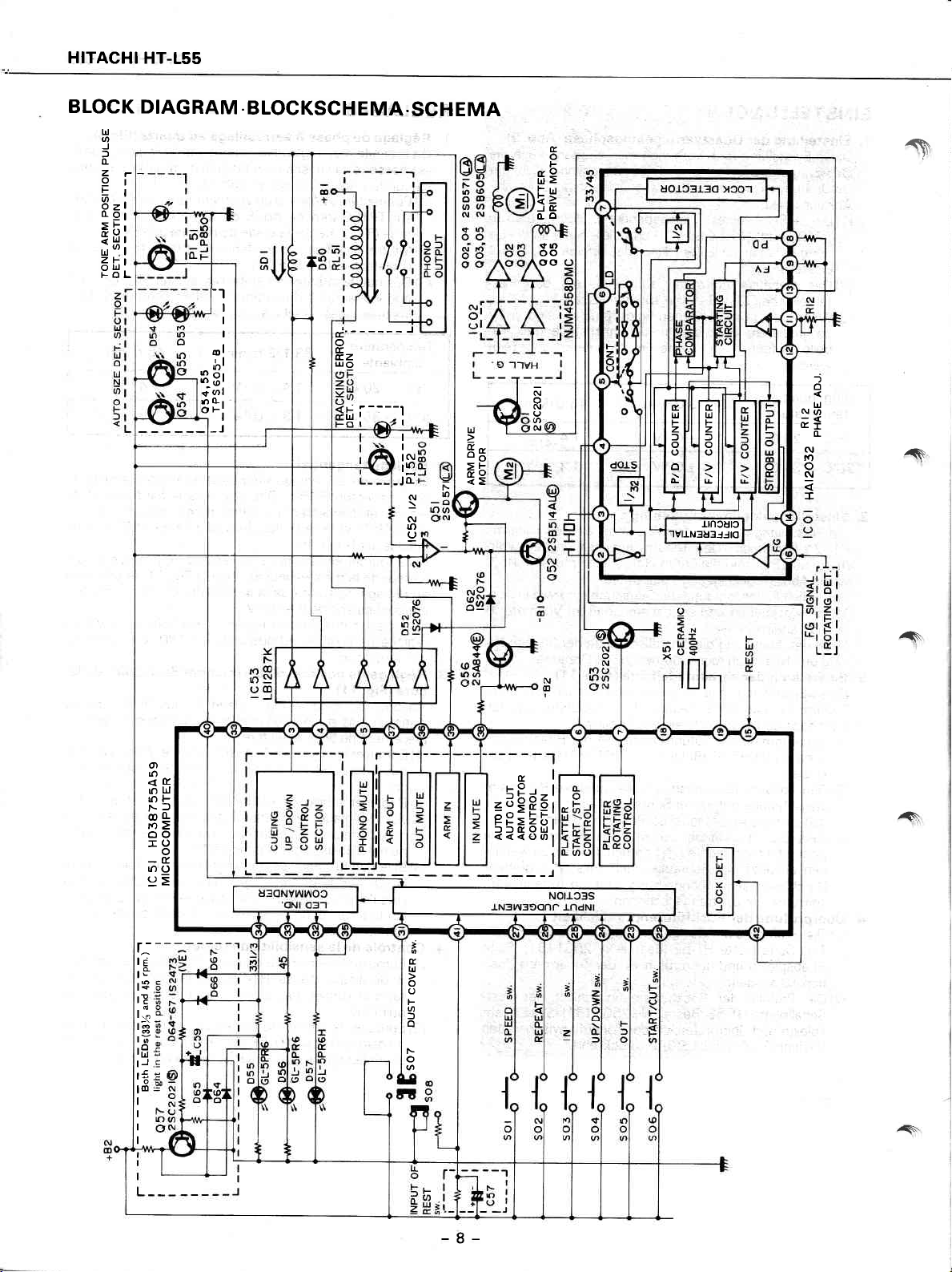
BLOCK
ul
o
J
f
fL
Zr
Ol
F;
8zt
aol
Esi
uot
Zlt
oùl'
FOL
DIAGRAM
[]
lr
I
I
rol
I
6
'1,
ll)
3r
ol
d
n
È;
o
_l
.
BLOCKSCH
EMA.SCH
d.------
o
É
É.2
qo
t
L
----l
i
^tu
^"1
I
I
lÀl
lrt
lfL
EMA
tr9
F rr-r
EA
Jtr
fLo
\fú)
oo
oo
f!
o
F
s
r
)
No
(rI
o
bl
fL
(\t
lr
o
N
î
I
N
o
N
I
a
U
N
5g
E!
N
(v
ro
(J
É.
t
lrJ
UJ
F
F
z
z
l
f
o
o
o
o
o
À
r
J-tncutc
"lvu-N3u3Jlto
r^-
rÉ
19
t3
rE
t_.
lsB
rl
rft
tJ
r6
lo
I
I
I
I
o
lr)
<fr
lf)ld
|r)F
Fl
oO
roE
oo
IO
-É.
tr)O
e=
îì
I
É.
LO
:-l
\ts
;ol
zó9
Ftr'
z<)t
PP;
OLll
llft
o
arl
_-J
I
t
É.
td
o
o
F
o
l
o
f.-
o
6
A
/s.
-8-
Page 9

REPLACEMENT
PARTS
LIST.
ERSATZTEILLISTE
.TABLEAU
DES
PIECES
7
SYMBOL
NO
c01
co2
c03
c04
co5
coq
co7
c08
c09
c10
c11
c12
5
c15
c16
c11
c18
c19
c2a
c21
c22
c23
c24
c25
c51
c53
c54
c55
c56
c57
c59
c'r o1
c1 01.
R01
RO2
RÓ3,,
RO4'
RO5
RO6
RO7
R08
R09
PART NO
0252323
0240106
0252521
o2t2521
02401 08
0252813
o275014
o275014
0252531
0230014
0240106
0252231
(
)
0252231
0240 1 08
0240 1 08
0209737
0252531
0252531
0252635
o252635
o252635
0209737
0209791
o252522
0240004
0240004
02528 1 5
0252631
o252805
o252331
'i1243899
4243901
o
29573
2956
0
o
3436b
29613
0
o
29609
o
2965 1
29649
o
29623
o
o
29613
CAPACITORS
Elecîrolytic
Cylindrical ceramic
Electrolytic
Elèctrolytic
Cylindrical
Elèctrolytrc
Mylar,
Mylar,
Electrolytic
Cylindrical ceramic
Cylindriial
Elecìrolyiic
Elebtlotyric,
Cylindrical ceramic
Cylindrical
Ceramic,
Electrolytic
Electrolytic
Ceramic, discal
Ceramic. drscal
Electrolytic
Cylindrical
Cylindrical ceramic
Electrolytic
Elecîrolytic
Electrolytic
Ceramic, discal
(forUS.A.&Canada)
Ceramrc, discal
(except
ceramic
film
film
ceramic
C
)
ceramic
díscal
-
ceramic
C
)
U.S.A & Canada)
RESISTORS
film
Carbon
1
. Carbsn.film
film
Carbon
Òo"mposition
film
Carbon
DESCRIPTION
33uF
O.O l4F
lOpF
1O1tF
O.O22tfi
3.3ttF
O.O33lF
0 033aF
1 OOaF
12pF
pF
O.O'l
1 OOaF
5
'l
OOsF
:
O.O22pF
OO22pF
0.014F
:
1OO1[
IOOpF
47O1tF
47OpF
47O1tF
O.01pF
0.0'l
aF
22pF
22OpF
22OpF
yF
4.7
'l
00aF
pF
O.47
1
00pF
0.01/F
f
lf
lO.O
I
I
I
33OO
100O
2200
3.3kO
22kQ
68kO
56kO 5%
82kQ
3.3kO
+-
+3Oo/o
'+
-r
'+5o/o
+3Oo/o
'+3Oo/o
+3Oo/o
'-[o9v"

HITACHI HT.L55
SYMBOL
NO.
R76
R77
R78
R79
R80
R82
BB3
H84
R85
886
R87
R88
R89
R90
A
R91
R92
R93
R94
R95
R96
R99
R1 01
R 102
R103
R 104
R 105
R'l 06
PART NO
29569
o1
29569
01
0129876
o't29647
0129631
0129641
01 29631
o129631
01 29661
01297o-1
19412
01
19421
01
o1 1 9046
o1 1
9046
o1 1 0601
0129561
o1 29639
o129647
o129621
o129643
01'29667
o129874
01298t4
o1 29868
o129910
o1 29890
0129581
Carbon film
(
)
Carbon film
Carbon f m
(
)
Carbon f m
Metal
oxide
Metal
oxide
Metal
Metal
Metal
(Fuse
resistor)
Carbon film
(
)
Carbon film
Carbon film
DESCRIPTION
22OA
22OA
18kO
47kQ
1OkO
47kO
l OkO
l OkO
1OOkg
lMA
82A
1O0O
274
27{l
1OA
l
OOO
22kg
47kO
6.8kO
kO
3
l9OkQ
1
skll
1.5kfJ
82OO
47kO
6.8kO
68012 t\o/o
+5%
+-5%
+5%
-+5o/o
-+5o/o
!.5o/o
-+5o/o
'r5%o
-r5%
+-5o/o
-r1Oo/o
+
1Oo/o
+.1O%
+1O%
+-5%
t-5o/o
t-ío/o
-+5o/o
+íoh
-t-5%
'r5o/o
'r5o/o
+5o/o
-r5o/o
-+E/o
+5%
sRDl/4P
5
sRD 1/4P
sRD 1/4P
5
sBD 1/4P
RS1
B
RS.IB
RNlB
RNI
B
Rt\1/48
sRD 1/4P
SRD
1/4P
\
SRD 1/4P
SYMBOL
NO
055
056
057
Pt5,1
Pt52
D01
DO2
D5'l
D52
D53
D54
D55
D56
D57
D58
5
D63
D64
5
D67
zDol
zDo2
zDo3
PART NO
2328982
2328083
2329612
2339491
2339491
2337372
233701 1
233701 1
233701 1
233947 1
233947 1
2337751'
2337751
2337752
2337A1 1
5
233701 1
2334011
5
233801 1
2337549
2337556
2337552
TPS605@
2SAB44G)
2SC2O21@
TLP-850
TLP-85O
DIODES
S1 BBAI O
152076
1
52076
152076
TLUR 1
53
TLUR 1
53
GL5PR6
GL-5PR6
GL-sPR6H
1
52076
(
)
152076
152473VE
5
152473VE
HZ-7C-3
HZ-|18-3
HZ-11A-2
DESCHIPTION
(LED)
{LED}
(LED)
lLED)
(LED}
tcol
tco2
tc51
rc52
rc53
oo1
ao2
o03
oo4
o05
o06
051
052
o53
o54
lCs
2369731
2367223
236997 1
2367222
236969
2329612
232A263
2328273
2328263
2328273
2317735
2328263
2329073
2329612
23289A2
TRANSISTORS
&
H412032
NJM 455BDMC
HD38755A59
NJM4558DMC
1
LB1287K
2SC2O21
2SD571
2S8605
2SD571
2SB6O5@
2SD330G)
2SD571
2S851
2SC2021
TPS6OsGD
4AL
@)
(G\
@
(E
@
G)
€)
-10-
R12
a
FO1,O2
FO1,O2
^
so1
so7 I
so8 I
RL51
xs't I
xol
AI
VARIABLE
0150961 lOok.flB
2727561
I
2727'lg1
I
2127 161
2639801
-06l
263987 1
2638902
2647631
I
2154421
278857 1
I
3924992
265836
RESISTOR
(for
speed
adj)
MISCELLANEOUS
Fuse-'l .0A
Fuse-T'l.OA'(except
larnp
Taat sWitch
Push switch
Push
Micro
Ceramic OSC
Crystal OSC
for
EP
1
E socket adaptor
(for
U.S.A. & Canada),
(for
holder
switch
miniature relay
ACCESSORIES
adaptor
U.S.A. & Canada)
(for
dust coverl
(for
restl
(for
US.A. & Canada)
double
voltage
sets)
I
!
^{'\
j
)
)
)
2
i
Page 11

HITACHI
HT-155
PRINTED
[
'*B,','":-B,f:
WIRING
BOARD
Earth,
.
PRINTPLATTEN
:Other]
.
PLAN
DE
BASE
P.D.,tM,Orgt
il
w-
il
,il
-
11
CONTROL
POWER
COR
P.W.B.
White
@
SUPPLY
D
-
Page 12

)t:
Axial
lead
t*.
Zylindrischer
x.
Condensateur
cylindrical
ceramic capacitor.
Keramikkondensator
céramique cylindrique
mit axialer
a conducteur
Zuleitung.
axial.
v
v
I
l)
'.
".""i
VOLTAGE
22O*24Ov
SELECTOR
sw.
ARM MOTOR
m
t
OL
É.
td
o
É.
o
o
z
IJ
Yz
v
Page 13

CIRCUIT
DIAGRAM
.
SCHALTPLAN
PLAN
DE
CIRCUIT
a\
-\
TRACKING
P.W.B.
CONTROL P.W.B.
R6t'62K
r4w- NJM45sADM
lC52
R55 t2K
D52
ts2076
o50
2sas44@
'^\
^
I
MOTOR
c37 0.47/50
P.W.B.
ROt
330
R2a
3,3x
col
1a/to
R2t
27K
-tóóta.z
MOTOR
STARTING
CIRCUT
lCOt
HAr2o32
PLL
^
Page 14

167r(E
tt:t
1614AL@
R9t
ro
R67A
to. i\
ù
ú2ts
Use
the electrolytic capacitors with explosion-proof valve
when the diameter of them is more than 1O mm
@.
I
SIND
cl BLOCK OIAGRAM
REIilO
o.c,
ENC,
:osr.
sr.
sw.
sr.
Ss.
Vditp
Ves
voo
oscr
iFr
Vgs
b32
PLL
FO1
R89
27 1W
R90
?7 1w
Lch
Rch
R8a
roo 1W
,A
RSt/2K
RSI/2K
FA1,O2
RS
410
227
B
for
US,CS
1A 125V
erceDt US.CS
r1A
I
I
-12-
Page 15

HITACHI
HT-155
A
.
ExpLoDED
vrEW
.
AUSETNANDERGEzocENE
DARSTELLUNG
.
vuE
ÉcurÉe
A
A
a
Page 16

w
v
@
@
v-
w
u-
Page 17

HITACHI
HT-155
ITEM
NO
a@
A.
,A
a@
A@
id
O
@
@
@-t
@
@
@
@
@
o
@
o
@
@
@
PART
NO
490141
4446901
3 1
80083
3180081
33399 1 7
3955501
3955541
444101
3371622
4690121
4690122
409875
3955401
395557
4690212
469021
224A152
2244153
2248154
2788681
263856
2748863
2748752
-eover
1'
Bottom
Foot
Foot
Foot
Cabinet
Dust
1
Hinge
Platter
Platter
Platter
1
D D
motor ass'y
Knob
1
Power
Power
1
Power
Power
Power
Swiîzerland,
Power
Micro
1
Dummy
Power supply
Power
U K & Australia)
DESCRIPTION
piate
spring
cover
(except
mat
(for
mat
U.S
ass'y
button ass'y
trans rubber
trans. rubber
transformer
transformer.(for
Sweden, U.K &
transformer
switch
switch
cord
supply
cord
U.S.A
)
A.)
(except
(for
U.S.A
(for
U
S.A & Canada)
France,
Australia)
(for
double voltage
(foi
U
A.
S
(except
U.S.A.,
U
S.A.)
)
West Germany
& Canada)
Canada,
sets)
ifr
,A
lTEM:.
NO.
@
@
@
@
@
@
@
@
@
@
@
@
@
@
@
@
@
PART
NO
.2749582'
2749622,,
27 18852
2718843
25441 12
2544113
2544752
2544753
395551 1
3954262
3952273
3364322
336433
395762
402257
1
2522735
46883
1 1
-468833-1
255373
1
2627221
4561434
4514603
'fuyer
.Power-supply
Phono
Phono
Linèar
Linear
Pick up
Pick up
p[ate
Unit
Pulley
puiley
Gear
Rail wire
1
Switch wire
1
Roller
Wire
ass'y
DC
motor
Motor
Belt
Cartridge
Voltage
(for
double voltage
3Q x 12DT
3l x I
(for
bottom
*pply
eord
cord
(for
cord
(excpet
cord
mechanisr:n
mechanism
(for
ass'y
(except
ass'y
ass'y
ass'y
rubber
(ercept
selector
bind
O bind
dotrble
plaîe,
{for
(fb'i
U.S.A
)
U S.A.)
ass'y
ass'y
U S.A
U.S A
U.S A
switch
sets)
screw
thread screw
others)
U.K:)
Australia)
U.S.A)
ffor
(except
)
)
)
(for
hinge)
U.S.A.)
Check
from-the
that
supply
exposed
ment repaitedtothe
r
O Checking
''Power
Next,
bòth
plug)
plate
kohms
method
swiîch
measure
poles
and
the input
ànd
cheik
or more.
parts
are
circuit before
customer.,
is
set to
ON
the resistance
of attachement
terminal
that the
resistanie
acceptably
returning
..
value
between
(Power
cup
(oùtside)
vàlue is
insulated
the instru-
the
supply
òf reai
5OO
'St
-15-
Page 18

HITACHI HT-155
DESCRIPTION
Pin
Description
Pin
Name
DO
D,I
D2
D3
D4
D5
D6 o
D1 o
D8
D9 o
D'10
D11
D12
D13 o o o
D14 o
D15 o
ROO o o START/CUT
R01
RO2
RO3
R10
R11
R12
R13
R20 o o o
R21 o o o 45 rpm LED
R22 o o o 33-1/3
R23 o o o Vacant
R30 o o OUT MUTE
R31 o o
R32 o o lN
R33 o
NTO o Encoder
INTl o Dust cover
(HD38755A59)
vo
/o
/o
/o
/o
o
o
o
o
I
/o
/o
/o
/o
NEW COMPONENT
OF
Resistant
Hidh Voltaoe
to
o Record size
o Resî switch
o
o o Vacant
o o Vacant
o
o Plunger output 5O%
o
o
o Turntable speed
o
o o
o
o o
o
o o
o
o
o
o o SPEED switch
o
o
o lN
Pull
up
MOS
o Vacant
o
o
o VaÒanl
Lock detector
Plunqer outout
AudÌo mutinq
TUTNtAbIE START/STOP
Vacant
Vacant
Vacant
Vacant
Vacant
OUT
UP/DOWN switch
lN
REPEAT switch
Vacanl
Reoeat LEO
OUT
oscl Ceramic oscillator
osc2
Vdisp o
Reset
VBB
VDD GND
VSS +1 0V
fesl +1 0V
t:
lnput
o
Output
o
Yes
o
Ceramic
GND
lnitial reset
GND
(>)
(<)
switch
(Arm
MUTE
(Arm
input
switch
swtich
rpm LED
(Arm
motor)
(Arm
motor)
position)
{arm
oscillator
1
OO%
selector
motod
motor)
inpuî
inpuî
Function
î\
î\
A
Pin No.
O
@
@
@
@
Pin
Symbol
D3 Vacanl
D4
D5
D6 UP
Vacant
Cueinq
olunqer
D5L
D6L
D7 Audio
muting control output
When the îonearm is UP, a LOW level signal is
When the tonearm is DOWN, a HIGH level
control
H
H
output
point
pin.
oin
Use
DOWN
start
output to mute cartridge output
signal is
output
16
-
DOWN
pornt
to release muting.
-
UP
start
I
I
UP
pornî
î
Page 19

A\
F\
A\
/\
Pin No.
@
@
@
I
úì
@
@
@
@
@
íÒ
@
@
@
@
@
@
@
@
@
@
@
€D
@
@
@
@
@
@
@
@
@
(}
@
Pin Symbol
D8 Platter rotation
D9 Platter
D10
I
D15
Vdisp
Reset lnitial
VBB
VDD Power
osc 1
osc2
lesl
Vss A
RO0
RO1
RO2
RO3
R10
R'l 1
Rl2
R13
INTO
INTI
R20
R21
R22
R23
830
R31
R32
R33
DO
D1
D2
Normally, this
When the
When the
Vacanî
Microcomputer MOS
Connected to VDD
A HIGH level signal is input
Normally,
Memory back-up
As the memory back-up
Ceramic
Used as a reference
Microcomputer tesî
As this feature is noî
voltage of + 1 OV is applied
Arm
When a HIGH level
When the tonearm is
Arm OUT
When a HIGH level
Arm UP/DOWN
When a HIGH level
Arm in
When a HIGH level
Repeat
When a HIGH
When the uniî has
Speed switch inpuî
Wheri a HIGH level
Vacanî
Vacant
Tonearm
The tonearm
Dusî cover swiîch input
When a HIGH
When a LOW level
Repeat LED
A HIGH level
45 rpm LED
A HIGH
33-1
A HIGH
Vacanî
Arm motor
Controls
Record size light
When a HIGH
Rest
When a HIGH
Turntable
When
contfol srgnal
pin
is
at LOW level.
platter
starts rotating,
speed control signal
platter
speed is 33- 1
power
pin @ (cND).
pin.
reset
a LOW level signal is input
power
pin. (Connected
supply
oscillator
START/CUT swirch inpuî
input
switch
switch input
swiîch input
swiîch inpuî
level signal is input,
position
posiîion
level signal is
output
signal is output
output
level signal is
rpm
LED output
/3
level signal is
drive ouîput
the movement
when
supply
sysîem is not
pin
input
microcomputer
of
pin-
used,
thìs is connected
signal is
in other
pin.
signal is input,
signal is input,
pin.
signal is inpul,
pin
already been
pin.
signal is ìnput,
detecîion
from
the rest
pin.
signal is input,
pin.
pin
output îo lighî
pin.
ourpur to
pin
of tonearm.
Output
@ @ @
H L
position
lock
a LOW level
H
L
H
level
detection
level
detection inpuî
H
H
L
pulse
input
signal is input,
input
signal is
signal is
input
pin
output
a HIGH
pin
output
supply
/3
(45)
to
pin
power
pin.
employed,
îo GND)
pin
input with the
than the rest
the unit is
pin
the unit is
the unit is
îhe unit
set to the
the
spéed is changed from
pin.
input
position
input,
the unit is
the unit is
to lighî
the repeaî
the
light the
pin
No
L
H
L L
H L
pin
record
.
pin
input,
the tonearm
pin.
plaîter
the
Use
(HA12032)
to lc
level siqnal is output
(HA1
lC
2032)
rpm,
is switched ON to
operation
(LOW)
a HIGH
to Vss
tonearm on
position,
to the
set
to DOWN
set
to the lN mode
set
lhe repeat
set to
repeat mode, the repeat mode
is
îhis
connected to VDD
(4O0
kz)
pin
@
the
unit is
the
ouî
level siqnal is ourpur
carry out
rest, the unit is
set to the cut mode
mode
(UP)
mode with the ronearm
mode.
33
is detected by counting the light
set to the dust cover open mode
to
set
the dust cover
LED
45 rpm LED
33-1/3 rpm LED
@
L
Stop
H
Moved
Moved outward.
DuriÀg
size detection is
is in the rest
is rotating
carried out
position
at
constant speed.
initial reset.
pin
to îhe
set
will be released
1/3
rpm to 45 rpm
pulses
mode
close
Tonearm movement
inward
playback.
@
(GND)
start mode
or vice
set to the UP
versa
(DOWN) poinî
-17-
Page 20

HITACHI
HT-155
BASCHREIBUNG
Stift-Beschreibung
Stift-Bezei-
chnrrno
DO EIA
D1
D2
D3 EIA o
D4 A
D5
D6
D7
D8 o
D9
D10 o
D11
D12 A o
D13 o o Frei
D14 A o o Frei
D15
ROO E o
RO1 E
RO2 E o
RO3 E
R'10 E/A
R ElA
Rl2 ElA
a
R
R20 o
R21
R22
R23 A o
R30
R31 A o
R32 o
R33
INTO E o
INTl E o
OSC 1
EIA
E/A o
E/A o
A
A o Schwinqspulenausgang
EIA o o Fre
DER NEUEN KOMPONENT
(
H D38755A59)
Bestàndig
hohe Soannuno
A
A o
A
A
gegen
o
o
o Schwingspulenausgang
o Tondàmofunq
o Drehzahlwàhler des
o
o
o
o o Wiederhol-Schalter
o
o o Frei
U
o
o RtjcHùhr-Tondàmof er
o Zufúhrung
Abnehmbarer
' 'MOS
o
o Fre
o
o
o
o
o Start/Unterbrechungs-Schalter
o Rrickf ùhr-Schalter
o
o
o
o
o 45 U/Min.-LED
o
o
osc2
Vdisp
Fesel E o
VBB
VDD
o
vss
esl +1OV
E
A
Eingang
Ausgang
Ja
Einoabe der SchallolattenoròBe
Stútze-Schalter
Verrieoelu nosd e'tektor
Frei
1 00%
50%
Plattentellers
Start/Stop-Schalter
Fre
Fre
Fre
Frei
Tonarmlift-Schalter
Zufúhr-Schalter
Drehzahlwàhler
Wiederhol-LED
33-1/3 U/Min
Frei
Bùckf
úhrung
Zufúhr-Tondàmpfer
(Tonarmstellunci)
Verkoder
Staubschutzdeckel
Keramikoszillator-Einqanq
Keramikoszillator-Eingang
(GND)
Erdunq
Anfanosrúckstelluno
Erdunq
{GND)
(GND)
Erduns
+10V
des
Plattentellers
(OUf
>)
(UP/DOWN)
(lN
{)
(REPEAT)
(SPEED)
(REPEAT)
-LED
{OUT)
(OUT) (Tonarmmotor)
(lN) (Tonarmmotor)
(lN) (Tonarmmoîor)
Funktion
(START/STOP)
(START/CUT)
(Tonarmmotor)
-ì
îl
î
.
Stift-Nr. Stift-Gode
O
@
@
@
@
D3 Frei
D4 Frei
D5
D6
D7
Kontrollausqangsstift
H
D5T
H
Tonarrnlift
der
Gehobene
Stellung
schwinqspule
(UP)
D6T
Kontrollausgangssîift der Tondàmpfung.
Wenn
Wenn
Tonarm
der
Tonarm unten
der
oben
(UP)
ist, wird ein
(DOWN)
ist, wird
Gesenkte
Sîartstellung
Tiefpegelsignal
ein Hochpegelsignal
-
(DOWN)
18
(LOW)
-
Anwendung
Gesenkte Gehobene Gehobene
(DOWN)
Stellung
ausgegeben, um den
(HIGH)
ausgegeben, um die
Startstellung
Tonabnehmerausgang
(UP)
Tondàmpfung
Stellung
zu dàmpfen
auizuheben
(UP)
î
Page 21

HITACHI HT-155
A
A
2î\
/\
Stift-Nr. stifr-code
@
o
@
ì
tb
@
@
@
@
@
(9
@
@
@
@
@
@
@
@
@
@
@
o
@
@
@
@
@
@
@
@
@
@
@
D8 Kontrollsignal ausgangsstift
D9 Kontrollsignalausgangsslift
D10
ì
DX5
Vdisp MOS-Stromversorgungsstifte
Reseî Eingangsstifi der
VBB
VDD
osc'l
osc2
Tesl
Vss Eine
ROO Eingangsstift
RO1
RO2
RO3
R10
R11 Eingangsstift
Rl2 Frei
R'l 3
NTO
INTl
R20
R21
R22
R23
R30
R31
R32
R33
DO
DI
D2 Eingangsstift
Normalerweise wird
Wenn der Plattenteller sìch
Wenn die Plattentellerdrehzahl
Fre
An VDD-Stift
Bei Einschalten der Stromversorgung
Normalerweise wird
Stromversorgungsstift
Da das speicherschutzsystem nicht in
(Erduns) (GND)
@
Anf
Stromversorgungsstift
Eingangsstift
Wird
als
Teststift des Mikrocompuîers
Bei Nichtgebrauch an Vss-Sîift
soannunq
Falls
ein
geschalleî
Falls
sich der
Eingangsstift
Bei Eingabe eines Hochpegelsignals
Eingangsstift
Bei eingabe eines Hochpegelsignals
(DOWN)
Eingangsstift
Bei Eingabe eines Hochpegelsignals
Eingangsstift
Bei Eingabe eines
Falls
sich das Geràt bereits
Bei Eingabe eines Hochpegelsignals
Frei
EingangsstiÍt der Tonarmstellungserf
Die Tonarmstellung wird
Eingangsstifî des Staubschutzdeckel-Schalters.
Bei Eingabe eines Hochpegelsignals
Bei
Eingabe eines Tiefpegelsignals
Ausgangsstift
Bei Ausgabe eines Hochpeqelsiqnals
Ausgangsstift
Bei Ausgabe eines Hochpegelsignals
Ausgangsstift der 33-1
Bei Ausgabe eines Hochpegelsignals
Frei
Ausgangsstift des Tonarmmoîorantriebs.
Steuert die
Keramikoszillaîors
des
Referenz
des
von + 1
des Start/Unterbrechungs-Schalters
Hochpegelsignal
Tonarm nicht
Rùckfúhr-Schalters
des
Tonarmlift-Schalters
des
befindet. und
des ZufúhrSchalters
Wiederhol-Schalters
des
Hochpegelsignals
Drehzahlwahlers
des
WiederholLED
der
45
der
Bewegungen
der Plattentellerumdrehungen an lC
Tiefpegelsignal
ein
dreht,
des Drehzahlwahlers
angsrúckstellung
jedoch
ein
des
Speicherschutzes
An
die Erdung
Mikrocomputer-Betriebs
wird
OV
(HIGH)
in
der
umoekehn
im
von
der Stútze aus
U/Min.-LED.
U/Min.-LED.
/3
des Tonarms.
(LOW)
jedqch
wird
so
33-1/3 bzw 45
des Mikrocomputers
anschlieBen.
(ON)
Tiefpeoelsional
Beîrieb ist,
(GND)
anschlieBen
@
anqewendet
eingegeben wird, wenn
Ruhesîelluna
(OUT)
(HIGH)
(UP/DOWN)
(HIGH)
(lN).
(HIGH)
(BEPEAT)
(HIGH)
Wiederhol-Betrieb
(SPEED)
(HIGH)
assung
(HIGH)
(LOW)
wird
(BEPEAT)
(HIGH)
(HIGH)
(HIGH)
Ausgangsstift-Nr
@ @
H T T
H
T H T T
H
Eingangsstift der
Bei
Eingabe eines Hochpegelsignals (HIGH)
Eingangsstift
Bei Eingabe eines
Bei Eingabe eines
der Ruhestellungselassung.
der Plattenteller-Verriegelungserfassung
H
T
SchallplattengròBen-Lichtimpulserfassung
Hochpegelsignals
Tiefpegelsignals
@ @
H
H T
(HIGH)
(LO\M
dreht sich der Plattent€ller
Anwendung
(HA1
ausgegeben
Hochpegelsignal
ein
an lC
lHAl2O32l
betraqt. wird ein Hoch-bzw Tiefoeqelsiqnal
U/Min.
wird an alle Stifte ein
(LOW)
einqeqeben.
wird
dieser Stift an den
anschlieBen)
kz) verwendet
{4OO
(START/CUT)
sich der
befindet. wird
Geràt auf RùckfùhrBetrieb
wird das
2032)
(HIGH)
Hochpegelsignal
lonarm
Geràt
das
auf Unterbrech-Betrieb
VDD-Stift
wird das Geràt auf Senk-Betrieb
wird das Geràt auf ZufLlhr-Betrieb
wird
das Geràt auf Wiederhol-Betrieb
befindet, so wird diese Funkîion
wrrd das Gerat von 33-'l
durch Zàhlen der Lichtimpulse erfaBt
wird das Geràt auf
das Geràt auf SchlieB-Betrieb des
leuchtet die die Wiederhol-LED auf.
leuchteî die
leuchtet
wird
befindet sich
45
U/Min
die 33-1/3 Ui
T
Stop
H
Bewegung nach innen
Bewegung nach
Wàhrend
die SchallplattengròBe erfaBt
der Tonarm in der Ruhestellunq
U/Min
/3
Òffnungs-Betrieb des Staubschutzdeckels
-LED
auf.
Min.LED
Tonarmbewegung
Abspielens
des
mit konsîanter Geschwindigkeit.
ausgegeben
(HIGH/LOW)
(HIGH)
eingegeben
(Erdung) (GND)
@
auf der Stùtze
befindet, wird
angeschlossen.
qeschaltet.
geschaltet
(UP)
DOWN
geschaltet,
wenn
geschaltet
geschalîeî
aufqehoben
auf 45 U/Min. umgeschaltet, und
Staubschutzdeckels
auf
auBen
geschaltet
ausoeoeben-
das Geràt auf
sich der tonarm
umgekehrt.
geschaltet
Start-Belrieb
oben UP
-19-
Page 22

DESCRIPTION DE LA
Description de broche
{HD38755A59)
NOUVELLE
COMPOSANT
Désignation
de brmhe
DO E/S
D1
D2 E/S
D3
D4
D5
D6
D-l
D8 5
D9 S
D10 S
D11
D12
D13
D14
D15 5 o
BOO E
R01
RO2
R03
R10
R11
R12
R13 E/S
R20 S
R21
R22
R23 ù
R30 S
R31
R32
R33
INTO
INTl
E/S
E/S
E/S
c
S o
S
e
5
S o o Libre
S
a
E
E
E o
E/S
E/S o
Eis
a
S
e
s
E o
E
oscl
OSC2
Vdisp o
Reseî E
VBB
VDD
VSS
Test
E
Entrée
e
Sortie
Résistant sous
h.rÉa hnci^n
o
o
o
o
o
o
o
o
o
MOS
d'excitation
o Libre
o Libre
Entrée de dimensions de disque
lnterrupteur de
Détecîeur de verrouillaqe
Sortie de
Sortie de lève-bras 50%
Assourdissemenî
Marche/arrét
Sélecteur
o o Libre
o
o
o o
o Libre
o Libre
Libre
o Libre
o
o
o
o lnterrupteur marche/anèt
o Touche
o Touche
o Toúclle d'entrée
o
o
o
Touche de
Touche
o Libre
o
o
o
o L bre
o LED de répétition
o LED 45 îrlmn
o o LED 33- 1
o
o Lrbre
o Assourdissement
o
o
o
o
Sortie
Assourdissement
Enîrée
Codeur
Couvercle
Entrée
Enlrée
Terre
Mise
Tene
Tene
+ lOV
+1 OV
O: Oui
[epos
lève-bras
10O%
du son
table
(OUT))
(tN
<)
(REPEAT)
(SPEED)
de sortie
du
d'entrée
du bras)
bras)
du
lecture
de
(START/CUT)
bras)
(lN
de
de vitesse de îable de lecture
de sortie
d'élévationlabaissement
répétition
de vitesse
îrlmn,
/3
(OUT) (moteur
(lN) (moteur
(positi'on
protèqe-poussière
d'oscillaîeur céramique
d'oscillateur céramique
(GND)
a'l'orisine
(GND)
(GND)
Fonètion
(START/STOP)
(U
(OUT
MUTE)
P/DOWN)
MUTE)
(moteur
(moteur
du bras)
^l
î
du bras)
a
Broche No.
Cr)
@
@
o
@
de broche
D3 Libre
D4 L bre
D5 Broche de sortie de
D6
D5.L
D6L
D7
commande de lève-bras
H
H
Usage
de reoéraqe
^
-20-
Page 23

HITACHI
HT-155
A,
A
F\
Broche No.
@
@
@
?
@
@
@
@
@
@
Íl
@
AD
@
@
@
@
@
@
@
@
@
@
broche
de
D8
D9
D10
Dl5
Vdisp Broche d'alimentation
Reset Broche de remise à l'origine
VBB Broche d'alimentation de secours a mémoire
VDD Broche d'alimentation
OSC 1
OSC2
fest Broche d'essai de micro-ordinateur
VsS Une tension
RO0
R01
R02 Broche
R03
R10
R1.l
R12
R13
INTO
Broche de sortie de signal
En
conditions
Ouand
Eroche de sortie de signal
Ouand le
en sortte
L bre
normales,
la rotation
plateau
de commande
cette broche est
plateau
dù
se
déclenche, un signal de
de commande de vitesse du
tourne
la
à
vilesse
I
MOS
a micro-ordinateur
Connectée à la broche Voo
Un
mise à l'origine
En conditions normales, un sional
Comme le circuil de secours a mémoire
Broche d'entrée d'oscillateur
Utilisé comme
Comme
Broche d'entrée d'interrupteur
Ouand un signal de
Ouand le bras de lecture est
Broched'entréedetoucheOUTòèSrasdelecture
Ouand un signal de
Ouand un signal de niveau
ture
Broche d'entrée d aníorce
Ouand
Broche d'entrée dè tòuèhé
Ouand un
Si l'unité est déjà eh niode
Broche d'entrée de touche
Ouand un signol de hivea+
vtce-vefsa
L bre
L bre
Broche
A
EUSCS.
de niveau HIGH
signal
référence
cétte caractéristique
+ 1 OV est
de
niveau
nrveau
de
d'entrée
est en
un siqnal de niveau HIGH
entréede
d
partir
position
signal
dè la
touche UP/DOWN
UP
niveau
de
détection de
posiiion
(Terre)
@
est délivré
de niveau
(Connectée
céramique
fonctionnement
du
n'est
appliquée
START/CUT
HIGH
est délivré
à une
HIGH
est
HIGH
(DOWN)
du bras'de lecture
ést delivré
réppîitio.n
de
est
HIGH
rÉpéîìlion,
dé
de vitesse
HIGH
position
de repos, lir
INTl
Usage
rotation du
de
au niveau
de 33-1/3
en
LOW
pas
n'est
(GND))
à la tene
du microordinaîeur
sollicitée, cette
Das
en entrée avec
position
autre
délivré en enîrée, l'unité se met en
bras
de
est délivré en entrée, l'unité se met en mode DOWN
en entrée.
.:l
délivre.en
le
mode de
plaîeau
LOW
niveau HIGH est
plateau
trlmn ou 45 tr/mn, un
quand
entrée
est delivré en entrée
sollicité, cette
broche
est connectée a
le
que
lecîure
de
€ntrée,
bras de
de repos, l'unité se met em mode d'arrét
celle
l'uniîé
se met
I'unité
se
répérition
sera libéré.
à circuit
à cìrcuit
l'appareil
broche est connectée à la broche VDD
(400
kz)
lecture au repos, l'unité se met
en
meî
en
(H
intégré
en
délivré
intégré
lHA12O32l
mis sous tension
est
la
mode
de sbrtie.
mode lN
mode
de
A12032)
sortie
signal
broche
r.
.
répétition
de niveau HIGH
(ON)
Vss
@
en
esl déllvré en entrée, la vitesse est modiflée de 33-1/3 trlmn
du bras de
posilion
lecture.
du bras
lecîure est
de
détectée
par
le
décompîe des impulsions
ou LOW est délivré
pour procéder
(Terre)
@
marche
(UP)
quand
le
bras de lec-
45
a
la re-
à
trlmn
lúmiri-
ou
/^[
@
@
@
@
@
@
@
@
@
@
@
R20
R21
R22 Broche
R23
R30
R31
R32
R33:
DO
D,I
D2
Broche
de sortie de LED de répétition
signQl
Uo
Broche
Un signal de niveau HlGil est
Un
Librd
Broche de sortie d'entraînement
de
dg
ryyeau.H-IGH
de sortie de LED 45 trlmn.,
de sortie de LED 33-1/3
signat dé,rilgaÉ
lecture
-
'@
H
H
t-
H L
Brgche
denîéetdlmpulsions
Ouand un signal de niveau
Broche d'entrée de détection
Ouand un
Broche
Ouand un
signal de niveau HIGH
d'entrée de
signal de niveau LOW
est.délivré
è-st
fllGH
Broche
@,:
'H:
H
détection
L
HIGH eat
pour
sortie
délivré
e3
.
en sortie
pour
allumer
allumer
trlrîn
dél'ùré
en
.Wíe Ègur
moteur
de
de-soriie No.
,@
L L
-:Ìl
:
L L
H L
lumineqs€sdo.djmèísions
délivré
position
de
de
au
est
délivréen
verrouillage
est
délibré
allumer la LED 33- l/3 trlmn
b'ras
de
@
H
en eitrée, la détection
repos
entrée, le
de îable de lecture
e[!6Ée, bup.-Ìeteaq:tÒqAelvitesse_coÒEFnte
en
la
la
ArrCt
Déplaceriiènt vers i'intérieui
Déplacement
En cours de
de
bras
répetítion.
LED de
LEDde 45 trlmó.
Mouvement
disque.
de dimensions de disque se déclenche
de lecture est a la
du
vers t'exllrie'ùii"
leclùre
bras
position
lecîure
de
"'
de repos,
-
"'
.È;:
-;,.
-21 -
Page 24

l-
--]
î
L
@HtrAcHt
HITACHI
Eastern
1 200Wall
07071,U.S.A.
Tel. 20'l-935-8980
ilid {lllestern Regional
1 400
Tel.
Southern
51 0Plaza Drive College Park,Georgia 30349,U.S.A.
Tel. 404-763-0360
Western Regional
401 West
90220,U.S.A.
ret
HTTACH|
321
Tel.
HTTACHT
3300Trans
H9RU'lBl,Canada
Tel . 514-697-9150
HITACHI
2050Hamburg
Tel
HTTACHT
Hitachi House,Station Road,
4DR,
Tel
HITACHI
Rissneleden
Sweden
Tel.
SALES CORPORATION OF AMERICA
Regional
Street
Morse Ave.,
31 2-593-1 550
Regional
Artesia Boulevard,Compton,California
.21 3-537-8383
SALES CORPORATTON OF
9 Koapaka
808-836-3621
(HSC
Canada
SALES
'l-0
, 7341
SALES
England
-848-8787
. 01
SALES SCANDINAVIA
08-98
52 80
Office
Wesl,
Lyndhurst, New Jersey
ice
Off
Elk Grove
Office
Office
Street Honolulu , Hawaii 9681
)CANADA
Highway, Pointe
EUROPA
Rungedamm
54,
(U.
(Service
8,
Box
7138,
Village, lll .
rNC.
GmbH
2,West
K.) Ltd.
Hayes, Middlesex
Centre: 01-848-3551)
'172-0TSundbyberg,
AB
60007, U .
HAWAil,tNC.
I, U .
Claire,
Quebec
Germany
S .A.
S
UB
HITACHI
Oerebekk
Fredrikstad, Norway
Tel.032-28255
SUOiIEN
Takojankatsu
Tel.Lahti 44
HITACHI
Kuldyssen 1
Tel. 02-999200
HITACHI
Bahnhofstrasse,
Switzerland
Tel. 064-51
HITACHI FRANCE
-1
1
8O/Wien
(0222)
(067)
Rue
97/115
.A
.
SAINT-DENlS,France
Tel . 201-25-00
HITACHI
A
Tet .
HITACHI SATES
56, Chaussee de
Nivelles,
Tel.
HITACHI
3
153 Keys Road
Iel .555-8722
HITACHI
Head
Office: 5-'1,
Cable Address :
SALES
1
HITACHI
SALES
SALES
NORWAY A/S
OY
P.O.
80,Finland
Box
620
Gressvik
15800Lahti
5,
241
A/S
3, DK-2630Taastrup, Denmark
A.G.
1
9, 5600 Lenzburg
3621
S.A.
Charles-Michels
SALES
439367/8
Belgium
22 71
SALES
Ltd . TOKYO
WARENHANDELS
Kreuzgasse
,
BELGIUM
Namur,B-1400
81
AUSTRALIA Pty Ltd.
Moorabbin
,
1-chome,Marunouchi,Chiyoda-
ku,Tokyo 10O,Japan
Tel
.Tokyo
"HITACHY "TOKYO
JAPAN
93200
2T,Austria
S.A./N.V.
,Victoria
(2121
1111
__l
-1
46
N
601
,
GiIBH
31 89Australia
^
^
HT.L55
TY
No,
347
EGF
Printed in Japan
(H,
FL)
 Loading...