

Hitachi HTS545050KTA300, HTS545040KTA300, HTS545050KTSA01, HTS545040KTSA01, HTE545050KTA300 Quick Installation Guide
Page 1
Quick Installation Guide
Hitachi Travelstar 5K500 &
Travelstar E5K500
Models: HTS545050KTA300
HTS545040KTA300
HTS545050KTSA01
HTS545040KTSA01
HTE545050KTA300
HTE545040KTA300
Page 1 version 1.0
Page 2
Hitachi Global Storage Technologies
Handling precautions
Set the drive down gently to prevent damage from impact or vibration.
Handle the drive carefully by the edges. Do not touch the exposed printed circuit board or any electronic components.
Do not press on the top or bottom of the drive.
Before handling the drive, discharge any static electricity from yourself and your clothing. With one hand touch an
unpainted metal surface, then touch the ESD bag with the other hand. Remain in contact with the chassis and the bag
for a minimum of two seconds.
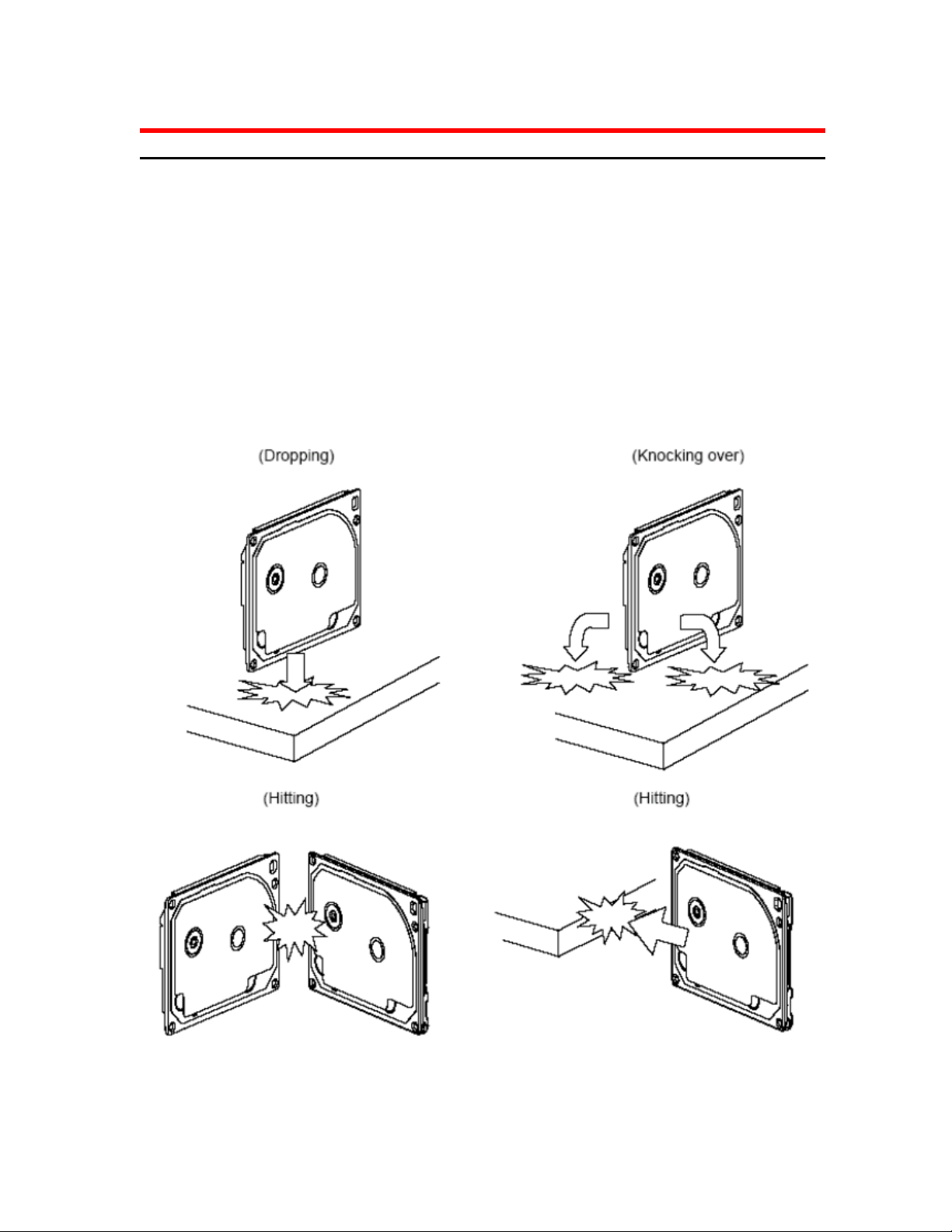
Vibration, shock and static electricity to the drive will damage the precision parts. In particular, prevent vibration or
shock generated by dropping, knocking over or hitting the drive. Also, avoid touching the electrical components
directly, which can discharge electrostatic energy and damage the drive.
Page 2 version 1.0
Page 3

Hitachi Global Storage Technologies
Mounting Recommendations
The mounting hole locations and size of the drive are shown below:
The drive will operate in all axes (six directions) and will stay within the specified error
rates when tilted ±5 degrees from these positions. Performance and error rate will stay
within specification limits if the drive is operated in the other permissible orientations from
which it was formatted. Thus a drive formatted in a horizontal orientation will be able to
run vertically and vice versa.
The recommended mounting screw torque is 0.3±0.05 Nm.
The recommended mounting screw depth is 3.0±0.3 mm for bottom and 3.5±0.5 mm for
horizontal mounting.
The user is responsible for using the appropriate screws or equivalent mounting hardware
to mount the drive securely enough to prevent excessive motion or vibration of the drive at
seek operation or spindle rotation.
Page 3 version 1.0
Page 4

Hitachi Global Storage Technologies
Interface connector
The figure below shows the physical pin location
All pins are in a single row, with a 127 mm (0.050”) pitch.
All V5 pins must be terminated.
The mating sequence for the case of back-plane blind-mate connector is referred to
OEM Spec.
Page 4 version 1.0
Page 5

Hitachi Global Storage Technologies
© Hitachi Global Storage Technologies
Hitachi Global Storage Technologies
Produced in the United States
1/08
Hitachi Global Storage Technologies’ trademarks
are authorized for use in countries and jurisdictions
in which Hitachi Global Storage Technologies has
the right to use, market and advertise the brands.
The Travelstar trademark is authorized for use in
the Americas, EMEA, and the following AsiaPacific countries and jurisdictions: Australia, Hong
Kong, Japan, New Zealand, South Korea and
Taiwan. Contact Hitachi Global Storage
Technologies for further information. Hitachi
Global Storage Technologies shall not be liable to
third parties for unauthorized use of Hitachi Global
Storage Technologies trademarks.
References in this publication to Hitachi Global
Storage Technologies’ products, programs, or
services do not imply that Hitachi Global Storage
Technologies intends to make these available in all
countries in which it operates.
Product specifications provided are sample
specifications and do not constitute a warranty.
Information is true as of the date of publication and
is subject to change. Actual specifications for
unique part numbers may vary. Please visit the
Support section of our website,
www.hitachigst.com/support, for additional
information on product specifications.
Photographs may show design models.
03 January 2008
Page 5 version 1.0
 Loading...