

Hitachi HG-E2100 Service Manual
No.
338
EGF
HGE-2lOO
SAFETY
The following
1.
2. Before
Since
parts.
Critical
iî is
completely
many
Especially
parts
returning
PRECAUTIONS
precautions
parts
are
safe
should be observed
in the
unit
parts
critical
marked
a
with
repaired
to
operate
unit
A
have
in the
in the
to
the
without
special
power
schematic
customer,
danger
CONTENTS
SPECIFICATIONS . TECHNISCHE
sPEC|FICAT|ONS....................
FEATURES
DISASSEMBLY AND REPLACEMENT.
AUSTAUSCHE' DEMONTAGE
ADJUSTMENTS
BLOCK D|AGRAM. BLOCKSCHEMA.
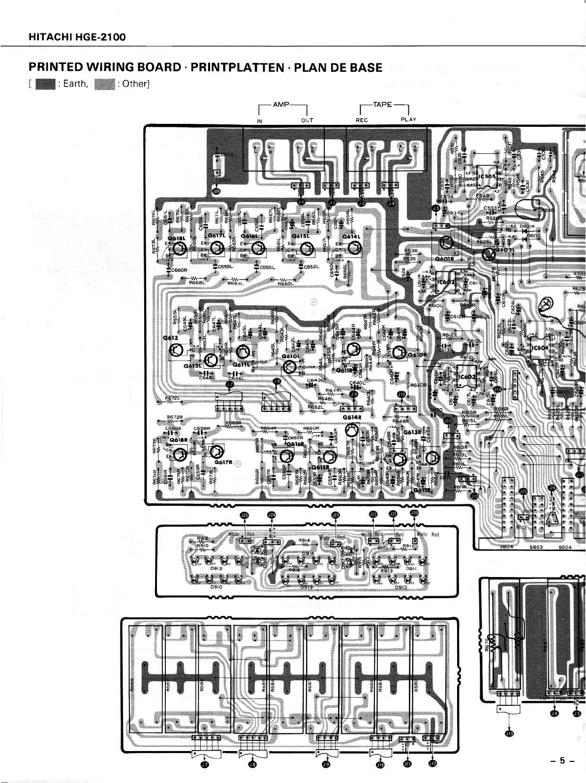
PRINTED WIRING BOARD
PLAN DE
CIRCUIT DIAGRAM
P|-AN
REP]ACEMENT
TABLEAU DES PtECES....
FRONT
BEOIENUNGSTAFEL. PANNEAUX
when
servicing.
safety related
circuit block
diagram and circuit board diagram.
the service
of electrical shock.
characteristics, always use
not be replaced with
should
technician must thoroughly test the
.
INHALT . SOMMAIRE
.
MERKMALE
84SE................
DE C!RCU|T...........
PARTS LIST. ERSATZTEILLISTE.
AND REAR PANET.VORDERE
.
CARACTERISTIOUES....................
.
EtNSTELLVERFAHREN
.
SCHALTPLAN
ET REMONTAGE.....................
.
PRINTPLATTEN
genuine
makers.
other
.
DATEN
.
AVANT ET
......................
ZERLEGUNG
.
RÉcr-ne
SCHEMA......................
..................................
UND HINTERE
Hitachi's replacement
unit to ascertain
UND
es...........
.
ARRIERE....... 11
1,2
......... 5
.........
that
3
3
+
4
6
7
SPECIFICATIONS
lnput
sensitivity/
lmpedance
Rated
output/
lmpedance
Total
harmonic
tion
Frequency
Signal-to-noise
Equalizer
quencies
SPECIFICATIONS
distor-
response
ratio
center fre-
MIC 1 mV/8
TAPE
150
mV/4 kohms
0.05%
20Hz-2O kHz
70
dB
9 elements
Hz, 5OO Hz,1 kHz,2k{z,4kHz,
kohms
15O mY/47
(1V
output)
-+2
(150
mV input)
63 Hz, 125
SOURCE/
kohms
dB
Hz,25O
8kHz,16kHz
AND PARTS
ARE
SUBJECTTO
Variable
range
ment
Echo
time
Delay
time
jacks
MIC
Tape
systems
Power
Power
supply
consumption
Dimensions
Weight
*
All
specifications
CHANGE FOR
of
adjust-
voltage
for
this
unit apply
IMPROVEMENT.
-r
1O
dB
variablel
variable
2
1
AC1
-24OV
|22O-24OV
20V
20 msec.
60 Hz,
50 Hz,
10w
(W)x
435
3ks
with
sec.-4sec.
1OO
-
-22OV
'l
10-120\l
50/60
Hz
(H)x
83
225
a flat equalization.
msec.
50 Hz,
(D)
mm
July
GRAPHIC EOUALIZER
1982
TOYOKAWA
WORKS
I
HITACHI
SICH
Bei Wartungsarbeiten
1. Da
2.yor
HGE-21O0
EITSMASSNAH
ERH
versòhiedene
Kritische
sind
chen
gewahrleistet ist.
Teile im
im Schaltplan
der Auslieferung
prúfung
unteàiehen, um
TECHNISCHE
Eingangsempfindlich-
keit/lmpedanz
Nennausgangsleistunl
lmpedanz
Klirrfaktor
Frequenzgang
Geràuschspannungs-
abstand
Entzerret-
Mittenfrequenzen
folgenden
die
sind
Teile dieses-Geràtes
Netzteil
und
im
eines
sollten
Diagramm
refarierten
sicherzustellen,
DATEN
1 mV/8
MIC
TAPE
150
mV/47 kO
/
kOhm
mV/4
150
(1V
dB
Ausgang)
kHz
(150
63
Hz,
O,O5%
20Hz-2O
70
Elemente
9
Hz, 500
8kHz,16kHz
M EN
SicherheitsmaBna
Sicherheitsfunkti
Geràtes
m
dB
àhnliche
an
den
daB sicherer
4 kHz,
nicht durch
der Schaltplatinen
kOhm SOURCE/
-r2
mV Eingang)
Hz, 1 25 Hz,25O
1 k{z, 2 k{z,
Kunden
muB derWartungstechniker
Betrieb
ohne
Verànderlicher
bereilch
Echozeit
Verzógerungszeit
Mikrofonbuchsen
Bandsystem
Stromversorgung
Leistungsaufnahme
Tabmessungen
Gewicht
*
Bei
sich
technischen
allen
um Werte
iginal-Hitachi-ersatzteile
nnzeichnet.
die
ersetzt
Gefahr
wer:den.
das Geràt
von elektrischen
Einstell-
+10dB
verànderlich
verànderlich
mSek.
(MlC)
2
1
60
50
(Blx
kg
dieses
Entzerrung.
bei
-12OV
-24OV
22O-24OV,50/60
1OW
435
3
Daten
linearer
verwenden.
Alle krilisehen
grùndli-
einer
Schlàgen
1 Sek.-4 Sek.
20 mSek.
Hz,
Hz, - 11O-12OV|
(H)x
83
Geràtes
-
-22OV50Hz,
Hz
225
handelt es
(T)
Teile
'lO0
mm
PRÉCAUTIONS
précautions
Les
1. Eiant donné
uniquement
pièces
aux
cants.
que
de càblage.
2. Àvant
présente
suivantes
que
de
pièces
des
critiques
pièces
Les
de retòurner
aucun danger
SPECIFICATIONS
Sensibilité
impédance
Sortie
impédance
Distortion
totale
Réponse en
Rapport signal/bruit
Fréquences centrales
d'égalisation
d'entrée/
nominale/
harmonique
fréquence
DE SÉCURITÉ
observées chaque
doivent
nombreux composants
du
critiques
I'appareil
de chocs
MIC
TAPE
150 mV/4
O,O5%
20Hz_2O
70 dB
gammes
9
Hz,
8kHz,16kHz
ètre
rechange d'origine
de
bloc d'alimentatiòn
accompagnées
sont
réparé au client,
électriques.
1 mV/8
kohms SOURCE/
15O mYl4l
kohms
(1V
sortie)
+2
||12
(150
mV entrée)
63 Hz.
5OO Hz,1
kHz,2k1z,4k{z,
I'appareil
de
Hitachi
qui
ne
du symbole
le technicien
kohms
dB
1 25 Hz,25O
fois
rossèdent
pour
doivent
qu'une
reparation
des caractéristiques
effectuer
en
A dans
doit
Réglage
un remplacement.
aucun cas
le schéma
procéder
de
riable
de l'écho
Durée
Retardement
Entrées
Mlc
Types de
Tension
d'alimentation
Consommation
Dimensions
Poids
*
Toutes
pour
les spécifications
une
doit
ètre
un essai
à
gamme
bande
égalisation
faite.
ètre
remplacées
de
relatives à
Ceci se
montage
complet
va-
r-
10 dB
variable
variable
2
1
12OV 60
-
-24OV
110-120V1220-240V
50/60
10w
435
3kg
de
Plate.
la sécurité,
rapporte
par
celles d'autres
le
et sur
schéma
pour
s'assurer
1 sec.-4sec.
20 msec.
Hz.
Hz,
50
Hz
(L)x
83
(H)x
cet appareil
utiliser
notamment
fabri-
de
qu'il
100 msec.
-
225
50 Hz,
(P)
-22OV
sont données
pla-
ne
mm
2
.
FEATURES
The audio
1.
bands
9
basic central
the
MERKMALE
frequency spectrum
in steps of
2. Large dynamic
in
are
Built-in
3.
used
the
electronic echo
.
CARACTERISTIOUES
1
octave
frequency.
range
resonance circuits.
semiconductor
with 1 kHz as
circuit
is divided into
inductors
4. Convenient
Two microphone
5.
recording
Mixing balance
6.
nuous variation
possible.
equalizer
inputs.
adjustment
mixing ratio.
of
selector
Microphone
switches
provides
mixing
conti-
1. Der Audio-Frequenzumfang
1
Schritten
mittenf
2. ln den
von
requenz eingeteilt.
Resonanzschaltungen
ter verwendet,
reich aufweisen.
Eingebaute elektronische
3.
1. Le
spectre
gammes,
9
quence
Des inducteurs
2.
centrale
dynamique
résonance.
de
3. Circuit
d'écho
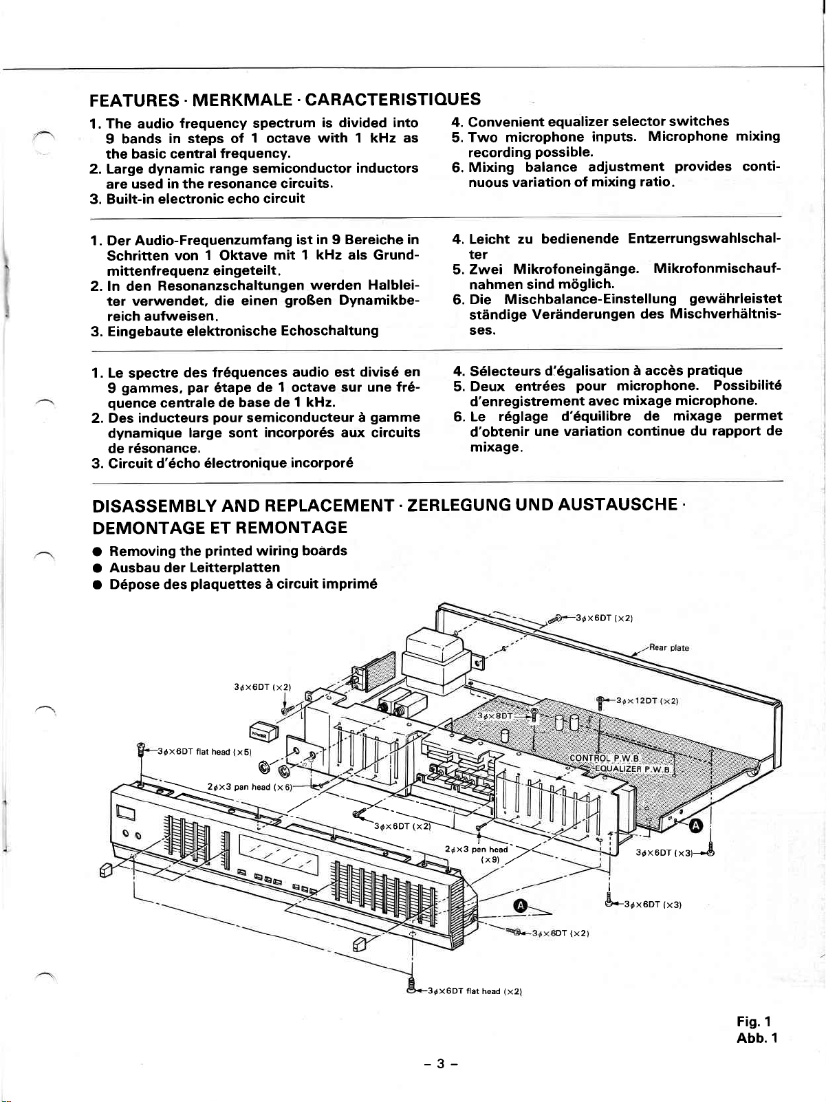
DISASSEMBLY
DEMONTAGE
Removing the
O
Ausbau der
O
Dépose des
O
Oktave
die einen
des fréquences
par
étape
de base de
pour
large sont
électronique
AND
ET
printed
Leitterplatten
plaquettes
mit 1 kHz als
de 1 octave
semiconducteur
incorporés
REPLACEMENT.ZERLEGUNG
REMONTAGE
wiring
à circuit
ist in 9 Bereiche
werden Halblei-
groBen
Echoschaltung
audio est
Dynamikbe-
divisé en
sur une fré-
1 kHz.
à
aux circuits
incorporé
boards
imprimé
Grund-
gamme
in
4. Leicht
zu bedienende
Entzerrungswahlschal-
ter
Zwei
5.
nahmen sind
Die Mischbalance-Einstellung
6.
stàndige
ses.
4.
Sélecteurs
Deux entrées
5.
d'enregistrement
6. Le
d'obtenir
mixage.
Mikrofoneingànge.
móglich.
Verànderungen
diégalisation
pour
avec
réglage d'équilibre
une variation continue
UND
AUSTAUSCHE
3dxoDT
Mikrofonmischauf-
gewàhrleistet
Mischverhàltnis-
des
a accès
microphone.
mixage microphone.
pratique
Possibilité
de mixage
rapport de
du
.
(x2)
permet
3dX6DT
flat head
(x5)
3óx6DT
X{l'anhead(x
oí
(X2)
R--ì>
3dx60T
(x2).-\
_:::--=.-
3óx6DT flat
-3-
26xg
1
paî
neaJ'V
txsl
head
,,/
(x2)
DT
(X2
3óx6DT,"r,*.8
I
c
è<-3dx6DT (x3)
Fis.1
Abb. l
HITACHI HGE-21OO
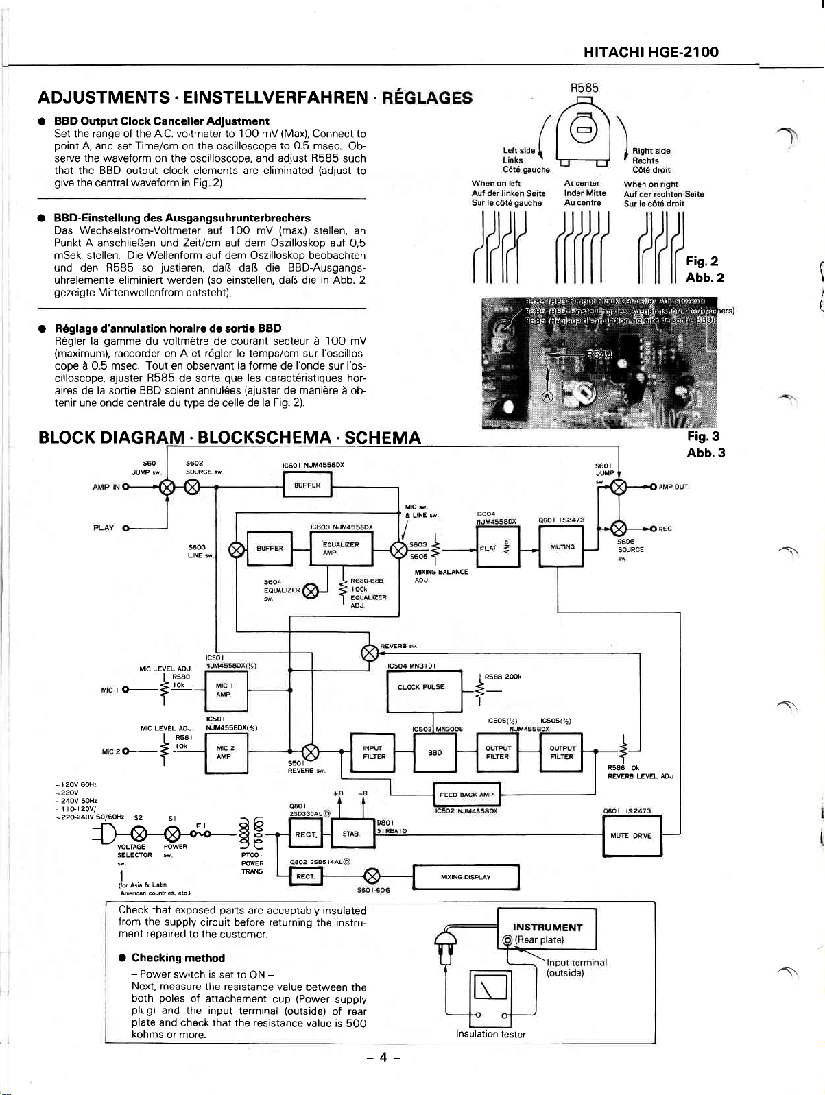
ADJUSTMENTS
BBD
a
Output Clock Canceller Adjustment
Set the range of the A.C. voltmeter to 1OO mV
point
A, and
set
the waveform
serve
.
EINSTELLVERFAHREN
Time/cm
on the oscilloscope
on the oscilloscope, and
(Max),
Connect
to 0.5 msec.
adjust R585
that the BBD output clock elements are eliminated
give
the
waveform in Fig 2)
central
O BBD-Einstellung des Ausgangsuhrunterbrechers
Das
Wechselstrom-Voltmeter auf 1OO
Punkt A anschlieBen und Zeitlcm auf dem Oszilloskop auf
mSek. stellen. Die Wellenform auf dem Oszilloskop beobachten
und den R585
uhrelemente eliminiert werden
gezeigte
Réglage
O
Régler la
(maximum),
cope à 0,5 msec. Tout en observant
cilloscope, ajuster
aires de la sortie BBD soient annulées
tenir une onde
Mittenwellenfrom entsteht)
d'annulation
gamme
raccorder en
BLOCK DIAG
justieren,
so
horaire de
daB daB die BBD-Ausgangs-
(so
einstellen, daB die in Abb. 2
soÉie
du voltmètre de courant secteur à
A
régler le temps/cm
R5B5
centrale
s60
de sorte
du type de
I
s502
SOURCE sw
et
.
la
que
celle
BLOCKSCHEMA
(max)
mV
BBD
forme de
les caractéristiques hor-
(ajuster
de la Fig. 2).
l'onde
manière
de
I NJM4558DX
tc60
stellen, an
sur
to
Ob-
such
(adjust
to
0,5
1OO
mV
l'oscillos-
sur I'os-
à ob-
.
SCHEMA
.
Fig.2
Abb.2
I
\
(
Fig.3
s60
JUMP
r
Abb.3
LEVEL AOJ.
MIC
o-Ère!-
*_+
I 2oV 6OHz
-
-220V
sOHz
-24OV
I tGl2OV/
-
5o/6otu
-22Ù-24ov
ffisE
52
SELECTOR
sw POVIER
I
Latin
(to.
&
Asia
American countries,
Check that exposed
from the
ment repaired
s603
LINE sw
I
tc50 I
NJM45s8OX(%)
AOJ
R5A I
tok
St
sw
elc
ì
supply circuit
to the
PToOI
rilNs
parts
are
before
customer.
s50t-
REVERB
acceptably insulated
returning
the
instru-
MIC sw
& UNE sw
MIXING
ADJ
BALANCE
I Rsaa 200k
*-
I
rc5os(%)
tc5o5(%)
R586
tok
REVERA LEVEL ADJ
^l
î\
O Checking method
Power
-
Next, measure
both
plug)
plate
kohms
switch is
poles
and
and
the resistance
of attachement
the input
check that the resistance
or more.
set lo
ON
-
cup
terminal
value
(Power
(outside)
between
supply
of
value
is 500
the
rear
-4-
lnsulation
^\
tester
HITACHI
HGE-210O
PRINTED
[
:Earth,
WIRING
:Other]
BOARD
.
PRINTPLATTEN
rot"__l
.
PLAN DE BASE
l--to"=-l
REC
PLAY
\
-5-
 Loading...