


USER'S
MANUAL
HITACHI INDUSTRIAL COMPUTER
HF-W2000 Model 48/45
INSTRUCTION MANUAL
WIN-62-0066-01
Read and keep this manual.
Read safety instructions carefully and understand them
before starting your operation.
Keep this manual at hand for reference.

First Edition, September 2016, WIN-62-0066 (out of print)
Second Edition, September 2016, WIN-62-0066-01
All Rights Reserved, Copyright © 2016, Hitachi Industry & Control Solutions, Ltd.
The contents of this publication may be revised without prior notice.
No part of this publication may be reproduced in any form or by any means without permission in
writing from the publisher.
Printed in Japan.
TP<IC> (FL-MW2007)

i
PREFACE
This manual is intended for operators of the HITACHI INDUSTRIAL COMPUTER HF-W2000
MODEL 48/45 (hereafter called as this equipment) contains information about the operation and
maintenance of various devices necessary for their routine work. And also this manual describes the
setup procedure of the OS installed in this equipment, namely the following pre-installed OS.
・Windows® 10 IoT Enterprise 2015 LTSB
・Windows® 7 Professional for Embedded Systems SP1
SEPARATE VOLUME CONSTITUTION
The manual of the HITACHI INDUSTRIAL COMPUTER HF-W2000 MODEL 48/45 consists of
the following:
・SAFETY INSTRUMENTS
・INSTRUCTION MANUAL (This manual)
・RAS FEATURES MANUAL
MANUAL CONSTITUTION
This manual consists of the following:
PREFACE
IMPORTANT NOTIFICATION
SAFETY INSTRUCTIONS
PRECAUTIONS
CHAPTER 1 GETTING STARTED
CHAPTER 2 OPERATION
CHAPTER 3 SET UP
CHAPTER 4 PRECAUTIONS while the OS is Running
CHAPTER 5 SPECIFICATIONS
CHAPTER 6 CHECKUP AND MAINTENANCE
CHAPTER 7 RESTORING THE FACTORY-SHIPPED CONDITION USING
A RECOVERY DVD
CHAPTER 8 MAINTENANCE OPERATIONS
CHAPTER 9 TROUBLESHOOTING
CHAPTER 10 SOFTWARE RAID1
APPENDIX HANDLING REPLACEABLE COMPONENTS

ii
[Trademarks]
•Microsoft®, Windows®, Internet Explorer® and Hyper-V® are registered trademarks of U.S.
Microsoft Corporation in the United States and other countries.
•Intel®, Intel® CoreTM i3 and Intel® Xeon® are trademarks of Intel Corporation in the United
States and other countries.
•DisplayPort and DisplayPort Certified Logo are registered trademarks of Video Electronics
Standards Association.
•Magic Packetllectronics Standards Associationd oft Corporation in the United States an
•All other product names (software and hardware) not from Hitachi described in this manual are
the registered trademarks, the trademarks, or the products of their respective owners.
•Zlib is used as a compression and decompression engine built in a part of the software of this
product. Its copyright notice is as follows:
Zlib ver 1.2.3 Copyright © 1995-2005 Jean-loup Gailly and Mark Adler

iii
IMPORTANT NOTIFICATIONS
• The contents of this manual cannot be copy without permission.
• The contents of this manual are subject to change without notice.
NOTICE
Depending on the type of failure, important files may be lost when you use this
equipment. Files can be lost by power failure and human mistakes during
operation in addition to the failure of the equipment. If such a situation occurs,
the files cannot be recovered. In order to prevent data loss, make it a routine to
save your files and establish a systematic schedule for backing up files.
● Harmonic Current Standards
This equipment is compliant with the JIS C 61000-3-2 Harmonic Current Standard.
● VCCI Notice
This is a Class A product based on the standard of the Voluntary Control Council for
Interference by Information Technology Equipment (VCCI). If this equipment is used in a
domestic environment, radio noise disturbance may arise. When such trouble occurs, the user
may be required to take corrective actions.
[Note for storage capacity calculations]
● Memory capacities and requirements, file sizes and storage requirements, etc. must be
calculated according to the formula 2n. The following examples show the results of such
calculations by 2n (to the right of the equals signs).
1 KB (kilobyte) = 1,024 bytes
1 MB (megabyte) = 1,048,576 bytes
1 GB (gigabyte) = 1,073,741,824 bytes
1 TB (terabyte) = 1,099,511,627,776 bytes
● As for disk capacities, they must be calculated using the formula 10n. Listed below are the
results of calculating the above example capacities using 10n in place of 2n.
1 KB (kilobyte) = 1,000 bytes
1 MB (megabyte) = 1,0002 bytes
1 GB (gigabyte) = 1,0003 bytes
1 TB (terabyte) = 1,0004 bytes

iv
● This equipment has been tested and found to comply with the limits for a Class A digital
device, pursuant to part 15 of the FCC Rules. These limits are designed to provide reasonable
protection against harmful interference when the equipment is operated in a commercial
environment.
This equipment generates, uses and can radiate radio frequency energy and, if not installed and
used in accordance with the instruction manual, may cause harmful interference to radio
communications. Operation of this equipment in a residential area is likely to cause harmful
interference in which case the user will be required to correct the interference at his own
expense.
● 이 기기는 업무용(A급) 전자파적합기기로서 판매자 또는 사용자는 이 점을
주의하시기 바라 며, 가정외의 지역에서 사용하는 것을 목적으로 합니다.
This equipment conforms to the electromagnetic wave for Industrial use (Class A).Vender or
user should take notice and use the purpose except for household use.

v
[Terms used in this manual]
Terms used in this manual are defined as follows.
・Install: An operation of installing software programs in the computer’s hard disk
・Setup: An operation of setting an environment so that the software can use in the computer
・Virtual machine: A virtual hardware environment provided by Virtual PC or Hyper-V®
・Host OS: A base operating system that operates the virtual machine
・Guest OS: An operating system that runs on the virtual machine
[Rereading terms]
This manual describes the Windows® operating procedure. Names of operations “sign in”
and “sign out” are replaced with “log on” and “log off” respectively depending on
Windows® types. Reread them as required.

S-1
SAFETY INSTRUCTIONS
Carefully read and fully understand the safety precautions below before operating
the equipment.
Operate the equipment by following the instructions and procedures described
in this manual.
Pay attention especially to safety precautions displayed on the equipment or in
this manual. Make sure you follow them. Otherwise, personal injury and
property damage including damage to the equipment may result.
A safety precaution is indicated by a heading as shown below. A heading is
either a safety alert symbol; a word such as “DANGER”, “WARNING”,
“CAUTION”, or “NOTICE”; or a combination of both.
This is a safety alert symbol. This symbol is used to signify
potential hazards that may result in personal injury or death.
Make sure you follow the safety message that follows this
symbol in order to avoid possible injury or death.
DANGER: This symbol is used to indicate imminent hazards that
will highly likely result in serious personal injury or
death.
WARNING: This symbol is used to indicate potential hazards that
may result in serious personal injury or death.
CAUTION: This symbol is used to indicate potential hazards that
may result in minor or moderate personal injury.
NOTICE: This symbol is used to indicate hazards that may result in
equipment or property damage but not personal injury.
The heading “NOTE” is used to indicate a cautionary note about handling and
operation of the equipment.
Do not attempt to perform any operation that is not described in this manual. If
there is any problem with the equipment, call your maintenance personnel.
Read this manual carefully and fully understand the directions and precautions
written in this manual before operating the equipment.
Keep this manual nearby so that you can reference the manual anytime you
need it.
Every effort has been made to specify the best precautions on the equipment
and in the manual. Nevertheless, unexpected incidents may occur. When you
use the equipment, you are asked not only to follow the instructions but also to
use your own judgment on safety.

S-2
SAFETY INSTRUCTIONS (Continued)
1. COMMON SAFETY PRECAUTIONS
Carefully read and fully understand the following safety precautions.
1.1 WARNING
This equipment is not designed and manufactured to be used for a life-critical
system that requires extreme safety. If there is a possibility that the equipment
may be used for this purpose, contact relevant sales representatives.
In case of smoke, a burning smell, or the like, unplug the power cord from
the outlet, disconnect the power cord from the outlet, and contact your
supplier or maintenance personnel. Using the faulty equipment without repair
may result in a fire or an electric shock.
This equipment has built-in hard disk drives. Do not hit the equipment or
give a shock or vibration to the equipment because that may cause the
equipment to fail. Should you drop the equipment or damage its chassis,
disconnect the power cord from the outlet and contact your maintenance
personnel. Using the faulty equipment without repair may result in a fire or
an electric shock. Do not give a shock to the equipment when unpacking or
carrying the equipment.
Do not modify this equipment because that may result in a fire or an electric
shock. The Manufacturer’s responsibility is exempted from any result arising
out of the user’s modification of the Equipment.
Do not operate this equipment without the dust filter because that may cause
of a fire. In addition, make sure you use the Hitachi brand dust filter.

S-3
SAFETY INSTRUCTIONS (Continued)
1.2 CAUTION
If the equipment drops or is tipped over, personal injury may result. Pay full
attention when transporting the equipment.
Make sure you do not catch or hit your fingers to cause personal injury when
unpacking or carrying the equipment.
Before you clean or replace the dust filter or the case fan of this equipment,
make sure you shut down the OS, disconnect the plug of the power cord
from the outlet, and wait for at least one minute. Otherwise, the injury of
hands and fingers may result.
Risk of explosion if battery is replaced by an incorrect type. Dispose of used
batteries according to the instructions.

S-4
SAFETY INSTRUCTIONS (Continued)
1.3 NOTICE
This equipment alone cannot guarantee the system safety. In order to ensure
sufficient safety of your system even when this equipment should fail,
malfunction, or have program bugs, you must add systemic protections such
as building external protective/safety circuits to facilitate safety measures to
prevent personal injury and serious accidents.
When you work on installation or replacement of hardware, wear an
antistatic wrist strap to prevent the buildup of static electricity.
When you tighten or remove a screw, use a screwdriver that fits the size and
type of the head of the screw to avoid stripping the head.
When you tighten a screw, drive a screw along the axis of a tapped hole
without adding too much torque in order to avoid damaging the thread.
This equipment is evaluated with the hardware specified in this manual.
Accordingly, use only the specified hardware when upgrading options or
replacing components. If any other hardware is used for such upgrade or
replacement, correct operation of the equipment will not be guaranteed.
Do not use the equipment in the environment full of dust or with corrosive
gas because that may cause the equipment to fail.
Do not give a shock to the equipment when unpacking or carrying the
equipment. If you do, that may cause the equipment to fail.
Make sure sufficient clearance is provided for air intake and exhaust in front
of and behind the equipment. Otherwise, the temperature inside the
equipment may rise and that may cause a failure or short life span of the
equipment. In addition, you need to ensure sufficient clearance for
maintenance work.

S-5
SAFETY INSTRUCTIONS (Continued)
Use the basic software that we specify. Operation is not guaranteed if any
other basic software is used.
Performing emergency shutdown (that is, unplugging the power cable from
the outlet or shutting off the circuit breaker without proper shutdown of the
OS) may cause the OS or applications not to work properly or may cause the
saved data to be corrupted. Never perform emergency shutdown unless you
must stop the system immediately due to some kind of error.
Keep in mind that if the power supply is cut, the system may not be able to
recover automatically.
If you insert or access a disk (CD or DVD), the system load may increase and
running applications may be affected. Do not insert or access a disk during
online operation (system operation).
Once disk (CD or DVD) access is complete, eject the disk from the DVD
drive. Leaving it in the DVD drive may result in failure.
Leaving the disk tray open may result in failure.
Make sure that the disk tray is closed when not in use.

S-6
SAFETY INSTRUCTIONS (Continued)
2. SAFETY WARNINGS IN THIS MANUAL
2.1 Safety Warning Indicated as “ WARNING”
Warning about the power supply unit (hazardous voltage)
Do not remove, disassemble, or modify the power supply unit. If you do, serious
personal injury or death may result due to an electric shock.
(Page 1-4)
The power cord that comes with the equipment is rated at the input voltage of
125 VAC. When using this equipment at over 125 VAC, prepare the power
cord fitting input voltage and inspect the safeness of this equipment enough.
When you connect the plug of the power cord to an outlet, make sure you use
an outlet with a ground terminal (ground pole) that is properly grounded.
In addition, you must install and use an earth leakage circuit breaker.
If you do not take these measures, that may result in a fire or an electric
shock.
Do not use a two-prong plug without a ground pole because that may result
in an electric shock or failure of the equipment.
(Page 1-14)
If any of the air intake and exhaust holes of the equipment is blocked, the
temperature inside the equipment may rise and that may cause a fire or
failure of the equipment. Make sure sufficient clearance is provided around
the equipment when you install. (See “1.6.2 Installation”.)
(Page 2-1)
In case of smoke, a burning smell, or the like, unplug the power cord from
the outlet, and contact your dealer or maintenance personnel. Using faulty
equipment without repair may result in a fire or an electric shock.
(Page 2-4) (Page 9-1)
Make sure to install a dust filter to equipment. If you do not, dusts enter into
the equipment and the short circuit fire may occur as a result.
(Page 6-1) (Page 6-22)

S-7
SAFETY INSTRUCTIONS (Continued)
Before you install or remove an extension board, make sure you shut down
the OS, unplug the power cord from the outlet, and wait for at least one
minute. If you install or remove an extension board without shutting down
the power, an electric shock or a fire may result.
(Page 6-8)
Before you install or remove an external control board, make sure you shut
down the OS, unplug the power cord from the outlet, and wait for at least one
minute. If you install or remove an external control board without shutting
down the power, an electric shock or a fire may result.
(Page 6-12)
Before you install or remove main memory, make sure you shut down the
OS, unplug the power cord from the outlet, and wait for at least one minute.
If you install or remove main memory without shutting down the power, an
electric shock or a fire may result.
(Page 6-15)

S-8
SAFETY INSTRUCTIONS (Continued)
2.2 Safety Warning Indicated as “ CAUTION”
Cautions about the fans (rotating objects)
Only maintenance personnel are allowed to remove a fan. If you remove a
fan yourself, your hand or objects may be caught by the rotating part of the
operating fan and personal injury may result.
(Page 1-4)
If you keep at high temperature this equipment, do not touch bare hands.
Otherwise you may result burns.
(Page 1-13)
Falling or dropping of the Equipment vertically placed on the desktop may
cause injury. Be sure to attach the vertical stand accompanying the
Equipment and place the Equipment with the vertical stand on a level
surface.
(Page 1-14) (Page 6-23)
When procuring an AC power cord, make sure that the cord has proper rating
and meets local safety requirements whatever applicable. Otherwise, an
electric shock or machine failure may result.
(Page 1-20)
Before you clean or replace the dust filter or the case fan of this equipment,
make sure you shut down the OS, disconnect the plug of the power cord
from the outlet, and wait for at least one minute. Otherwise, the injury of
hands and fingers may result.
(Page 6-1)
Before you start the work, make sure you shut down the OS, unplug the power
cord from the outlet, and wait for at least one minute. Otherwise, an electric
shock or failure of the equipment may result.
Do not directly touch the parts inside the equipment with your hand when you
install or remove an extension board. Those parts are hot and if you touch them,
you may get burned. In addition, if you touch them, they may get damaged and
that may result in failure of the equipment.
(Page 6-6)

S-9
SAFETY INSTRUCTIONS (Continued)
When you install the cover of the equipment, do not put your fingers inside
the cover. If you do, your fingers may get caught and injured.
(Page 6-7)
When you install or remove a HDD or SSD, make sure you do not cut your
fingers on the protrusions.
(Page 6-18)
When you install or remove a DVD drive, make sure you do not cut your
fingers on the protrusions.
(Page 6-21)
This equipment uses a lithium battery. When you replace the lithium battery,
make sure you replace it with one specified by the Manufacture. Otherwise,
an explosion, a fire, a burst battery, heat generation, a liquid spill, or gas
generation may result.
Install the battery in correct polarity. Installing it in wrong polarity may cause
abnormal reaction such as charging or shorting, resulting in a liquid spill, heat
generation or a burst battery.
(Page 6-24)
Do not directly touch the parts inside the equipment with your hand when you
install or remove a jumper socket. Those parts are hot and if you touch them,
you may get burned. In addition, if you touch them, they may get damaged and
that may result in failure of the equipment.
(Page 6-26)

S-10
SAFETY INSTRUCTIONS (Continued)
2.3 Safety Warning Indicated as “NOTICE”
Depending on the type of failure, important files may be lost when you use
this equipment. Files can be lost by power failure and human mistakes during
operation in addition to the failure of the equipment. If such a situation occurs,
the files cannot be recovered. In order to prevent data loss, make it a routine to
save your files and establish a systematic schedule for backing up files.
(Page iii) (Page C-7)
Before you move this equipment, make sure you shut down the OS,
disconnect the plug of the power cord from the outlet, and wait for at least
one minute. If you do not, the HDDs and other devices may fail.
When you transport or carry the equipment, pack it in a dedicated container
(the container and packing materials used when the equipment was
delivered). If you use other container or packing materials, that may damage
the equipment.
Do not use damaged or broken dedicated container when you transport or
carry the equipment. If you do, that may damage the equipment.
Due to the property of inrush current restraint method with this equipment,
inrush currents may increase than usual if the power is turned on before the
power supply unit has sufficiently cooled off naturally after the power
has been turned off. Before you turn on the power again, wait at least
one minute after you have turned off the power. Otherwise, the inrush
currents may affect the breaker connected to the equipment and also
the life span of the equipment itself.
(Page C-1)
Never hot-swap HDDs or SSDs because that may cause failure of the equipment and
HDDs or SSDs. Before you replace an HDD or SSD for the A model or the S model,
make sure you shut down the OS, unplug the power cord from the outlet, and wait
for at least one minute.
When using a USB port, check the orientation of the USB connector, and then
insert the connector slowly. Otherwise, the USB port may be damaged.
Do not remove or insert a USB device during online operation (system operation)
because that may affect currently running applications.
If you insert or access a CD or DVD, the system load may increase and running
applications may be affected. Do not insert or access an optical disc during online
operation (system operation).
(Page 1-4)

S-11
SAFETY INSTRUCTIONS (Continued)
Before you move this equipment, make sure you shut down the OS,
disconnect the plug of the power cord from the outlet, and wait for at least
one minute. If you do not, the HDDs and other devices may fail.
When you transport or carry the equipment, pack it in the dedicated container
(container and packing materials used when the equipment was delivered).
If you use other container or packing materials, that may damage the equipment.
Do not use damaged or broken dedicated container when you transport or
carry the equipment. If you do, that may damage the equipment.
(Page 1-14)
Do not route the interface cables, etc. (including cables for other devices such
as a PC) near the power cord. If you do, a failure or malfunction of the equipment
may result.
Do not connect or disconnect an interface cable while the power for this
equipment or for the remote device is on. If you do, failure of the equipment
may result due to a short circuit between the power supply and the ground.
When an interface cable comes off while the power for the equipment is on,
shut down the OS and disconnect the power cord from the outlet.
Disconnecting the power cord from the outlet without shutting down the OS
might destroy the internal files.
When you connect a cable for external contacts, make sure you connect the
cable to a connector for the external contacts (EXT). It is possible that a
voltage as high as 40 VDC can be applied to the cable through a relay load.
If you connect the cable to the wrong connector, that may cause failure of the
equipment.
(Page 1-17)
Performing emergency shutdown (that is, unplugging the power cord from
the outlet or shutting off the breaker without proper shutdown of the OS)
may cause the OS or applications not to work properly or may cause saved
data to be corrupted. Do not perform emergency shutdown unless you must
stop the system immediately due to some kind of error.
If you turn off the power at the source of AC the power, the system may not
be able to recover automatically.
(Page 2-4)

S-12
SAFETY INSTRUCTIONS (Continued)
If you insert or access a CD or DVD, the system load may increase and
running applications may be affected. Do not insert or access an optical disc
during online operation (system operation).
When you finish accessing a CD or DVD, eject the disc from the DVD drive.
If you leave the disc in the DVD drive, failure may result.
If you keep the disc tray open, failure may result. When you do not intend to use
the DVD drive, keep the disc tray inside the DVD drive.
Do not use an unbalanced CD or DVD due to attached labels and so on; a
disc with cracks, scratches, or vertical deviation; or a disc with a nonstandard shape. If you do, an abnormal sound or vibration may be generated
and failure of the equipment may result.
(Page 2-5)

S-13
SAFETY INSTRUCTIONS (Continued)
Before you move this equipment, make sure you shut down the OS,
disconnect the plug of the power cord from the outlet, and wait for at least
one minute. If you do not, the HDDs and other devices may fail.
When you transport or carry the equipment, pack it in the dedicated container
(container and packing materials used when the equipment was delivered).
If you use other container or packing materials, that may damage the equipment.
Do not use damaged or broken dedicated container when you transport or
carry the equipment. If you do, that may damage the equipment.
(Page 6-1)
If you wash a dust filter, dry it completely before re-attaching it to the
equipment. If you use the equipment while its dust filter is not completely
dry, the equipment may fail. When you use a detergent to clean a dust filter,
make sure you use a neutral detergent. If you use other types of detergent, the
dust filter may lose its function.
(Page 6-2)
Make sure you disconnect all external cables connected to the equipment
before you install or remove an extension board. Otherwise, failure of the
equipment may result.
(Page 6-8)
Always attach a slot cover to each unused extension slot. Otherwise, failure
of the equipment may result.
(Page 6-10)
Make sure you disconnect all external cables connected to the equipment
before you install or remove external control board. Otherwise, failure of the
equipment may result.
(Page 6-12)

S-14
SAFETY INSTRUCTIONS (Continued)
Make sure you disconnect all external cables connected to the equipment
before you install or remove main memory. Otherwise, failure of the
equipment may result.
(Page 6-15)
The orientation of a main memory module on a connector is fixed. When you
install a main memory module, make sure the orientation is correct.
Otherwise, failure of the equipment may result.
Do not install main memory modules with different capacities on slot A1 and
slot B1. If you do, the modules may not be recognized.
(Page 6-16)
Put the HDD or SSD on a shock-absorbing material such as an antistatic
cushion even for a temporary task. If you put an HDD or SSD directly on a
hard surface such as a desktop, a failure or a shorter life span of the unit or
loss of data may result due to possible jarring or shock.
Never remove the screws on an HDD or SSD while the power to the unit is
on. Never hot-swap HDDs or SSDs. If you do either of these, failure of the
equipment or the drive may result.
Before you replace an HDD or SSD, make sure you shut down the OS, unplug
the power cord from the outlet, and wait for at least one minute.
Install or remove an HDD or SSD only if necessary, for example, when you need to
replace an HDD or SSD due to failure. If you do it frequently, failure of
the equipment may result.
Fully insert an HDD or SSD. Loose contact and missing screws may result in
failure.
Do not give a shock to an installing HDD or SSD and the already mounted
HDD or SSD during installing. If you give a shock to an HDD or SSD,
failure of the drive may result.
(Page 6-18)
In the case of the B model, when you install or remove an HDD, make sure
the drive bay number is correct. If you remove an HDD and install it in
a different bay, a configuration information mismatch occurs and
the equipment may not start or the data stored on the HDD may be lost.
(Page 6-19)
Make sure you do not apply too much force to the connector of the DVD
drive and the top of the DVD drive. If you do so, failure of the DVD drive
may result.
(Page 6-21)

S-15
SAFETY INSTRUCTIONS (Continued)
A recovery DVD contains an image file created for the hardware
configuration at the factory shipment. If the hardware configuration has
changed from the one at the factory, the OS may not start after restoration
work. Remove all external storage devices to resume the hardware
configuration at the factory shipment before you perform restoration work
using a recovery DVD.
When a recovery DVD is used, all data in the system drive is deleted. Back
up the data beforehand as required.
(Page 7-2)
Although this Equipment featuring RAID1 is more reliable than general
systems, it is still prone to the loss of data in the HDDs. Not only a
machine failure but also an unexpected power failure or an operation
error may cause data to be lost for good. To prevent such loss of data,
implement scheduled data backup in daily operation. Also, protect the
power source from undesirable interruptions by such means as UPS.
This Equipment is evaluated based on the specific HDD models authorized by
the Manufacturer. Replace only with specific HDD models authorized by the
Manufacturer. Otherwise, the existing data in the HDD may be lost.
Also, always observe the recommended replacement interval for HDDs (Refer to
“APPENDIX HANDLING REPLACEABLE COMPONENTS”).
Since each Equipment has its own RAID1 configuration information (e.g., serial
number), you cannot swap HDDs even between two units of this Equipment.
If you dare, the stored data in the newly installed HDD will be erased with
automatic RAID1 rebuilding process due to inconsistency of the RAID1
configuration information. If you own multiple units of this Equipment, manage
use and inventory of HDDs so that they are not inadvertently mixed.
As a replacement HDD, do not use an HDD previously used in the A model
or the B model. If you do, this equipment may not operate properly or the
data on the HDDs may be lost because of configuration information mismatches
or other reasons.
Use a brand-new HDD (an unused HDD) or an HDD to which "Initialize Drives"
has been applied (see "10.6.7 "Initialize Drives") as a replacement HDD.
(Page 10-1)
Maintenance of a RAID1 system requires a high level of expertise. Should any
mistakes be made during the work, the data stored on the HDDs may be lost.
When HDD1 and HDD2 are installed, their capacities must be the same.
(Page 10-2)

S-16
SAFETY INSTRUCTIONS (Continued)
Never remove an HDD when the HDD status lamp of the HDD is OFF.
If you do, the data stored in the HDD gets corrupted.
Wear cotton gloves when replacing an HDD in order to prevent problems
caused by static electricity. If you do not, the data stored on the HDD may
get corrupted.
Make sure you check the correct procedure before you start the work.
If you do not follow the correct procedure, the data stored on the HDD may
be lost.
As a replacement HDD, do not use an HDD previously used in the A model
or the B model. If you do, this equipment may not operate properly or the
data on the HDDs may be lost because of configuration information mismatches
or other reasons.
Mount an HDD securely. Loose contact and missing screws may result in a failure.
Do not subject an HDD you are mounting and the already mounted HDDs to shock
while replacing an HDD.Otherwise, failure of the drive may result.
Until the rebuild is complete, avoid shutting off the power for this equipment or
attaching and detaching HDDs. Otherwise, the data on the HDDs may be lost or
a failure may result.
(Page 10-9)
If you apply the recovery method for an offline HDD to an HDD that was set
to offline by something other than the RAS software, the HDD may not be
recovered, or even if it is recovered, the HDD may not work properly.
Use the recovery method for an offline HDD only for the purpose of evaluating
the equipment. If you apply the recovery method for an offline HDD to
equipment actually used in the field, for example, a system in normal operation,
malfunctions may result, including data loss.
If an HDD is automatically set to offline by the equipment, the HDD may
possibly be out of order. Do not apply the recovery method for an offline HDD
to such an HDD.
An HDD recovered by the recovery method for an offline HDD must not be
used for equipment actually used in the field. If used, malfunctions may
result, including data loss.
(Page 10-19)

S-17
SAFETY INSTRUCTIONS (Continued)
Wear cotton gloves when replacing an HDD in order to prevent failure
caused by static electricity. If you do not, the data stored on the HDD may
get corrupted.
Make sure you check the correct procedure before you start the work.
If you do not follow the correct procedure, the data stored on the HDD may
be lost.
(Page 10-20) (Page 10-22)
Wear cotton gloves when replacing an HDD in order to prevent failure
caused by static electricity. If you do not, the data stored on the HDD may
get corrupted.
Make sure you check the correct procedure before you start the work.
If you do not follow the correct procedure, the data stored on the HDD may
be lost.
As a replacement HDD, do not use an HDD previously used in the A model
or the B model. If you do, this equipment may not operate properly or the
data on the HDDs may be lost because of configuration information
mismatches or other reasons.
Do not replace the two HDDs at the same time. If you do, the data gets
corrupted.
When you replace an HDD, make sure that you set the HDD into the offline
mode in the Hardware status window, and then remove that HDD and
mount the replacement HDD. If you mount or remove an HDD when the
hardware status cannot be checked, for example, immediately after the OS
starts, a failure may result.
(Page 10-23)
Do not use a replaceable component for longer than the recommended
replacement cycle. If you do, a deteriorating or worn-out component may
cause the equipment to fail.
(Page A-1)

S-18
SAFETY INSTRUCTIONS (Continued)
3. WARNING LABELS
The warning labels are attached to the following position on the equipment.
Label
Label

S-19
SAFETY INSTRUCTIONS (Continued)
4. PRECAUTIONS WHEN YOU USE THE LASER
The DVD drive uses a laser.
Do not look into the laser beam, whether directly or indirectly, because that
may cause a visual impairment.
5. NOTICE LABEL
The notice label is attached to the following position on the equipment.
Label
CLASS 3B VISIBLE AND INVISIBLE
LASER RADIATION WHEN OPEN AND
INTERLOCKS DEFEATED AVOID
EXPOSURE TO THE BEAM.
Label

S-20
SAFETY INSTRUCTIONS (Continued)
6. DISPOSING THE EQUIPMENT
This Equipment contains materials potentially harmful to environment if
improperly abandoned. When you dispose of this Equipment, observe local
laws and regulations whatever applicable.
7. EU BATTERY DIRECTIVE (2006/66/EC)
This symbol mark is valid in countries inside the European Union. This symbol
mark is specified in Article 20 “Information for end-users” and Annex II of the
EU directive 2006/66/EC.
This equipment is equipped with a lithium battery. When you remove the
battery, follow the instructions in the “6.4 Removing the lithium battery”.
In the European Union, a separate collection system for used battery and
accumulator has been in place. Process batteries and accumulators
appropriately at a local collection/recycle center.
EU

C-1
PRECAUTIONS
1. PRECAUTIONS ABOUT THE EQUIPMENT
NOTICE
Before you move this equipment, make sure you shut down the OS, disconnect
the plug of the power cord from the outlet, and wait for at least one minute. If
you do not, the HDDs and other devices may fail.
When you transport or carry the equipment, pack it in a dedicated container
(the container and packing materials used when the equipment was delivered).
If you use other container or packing materials, that may damage the
equipment.
Do not use damaged or broken dedicated container when you transport or
carry the equipment. If you do, that may damage the equipment.
Due to the property of inrush current restraint method with this equipment,
inrush currents may increase than usual if the power is turned on before the
power supply unit has sufficiently cooled off naturally after the power has been
turned off. Before you turn on the power again, wait at least one minute after
you have turned off the power. Otherwise, the inrush currents may affect the
breaker connected to the equipment and also the life span of the equipment
itself.
(1) TRANSPORTING THE EQUIPMENT
<Required actions>
・ When you transport or carry the equipment, pack it in a dedicated container (the
container or packing materials used when the equipment was delivered). When you
transport or carry the equipment in a chassis, protect the equipment so that any vibration
and shock the equipment is subjected to is within the specifications provided.
・ Keep a dedicated container (the container or packing materials used when the
equipment was delivered). You can then use them later when the equipment is
transported or carried.
(2) INTERFACE CABLES
<Precautions>
・ Do not pull on a cable with excessive force.
・ In order to meet the EMC standards (FCC, CE, VCCI), use shielded cables for the
interface cables (display interface cable, keyboard interface cable, and mouse interface
cable) connected to the equipment.
<Required actions>
・ Route the cables in a neat and orderly manner alongside the device so that those cables
do not catch on hands or feet. If the power cord is disconnected during operation of the
equipment and the power is lost, crucial data stored on the hard disk may be break.

C-2
(3) CONNECTOR
<Precautions>
・ In order to connect a connector properly, you need to insert it with the proper
orientation and at the proper angle. If a connector is not inserted properly, the connection
may fail or malfunction.
・ Make sure there are no loose I/O cable connectors on the equipment.
(4) POWER SUPPLY
1. Power Voltage
<Required actions>
• Confirm that the voltage of the power input to the equipment is within the specified range
(100Vto240VAC). If the voltage of the power input is close to the upper or lower limit of
the specified range, you should treat it as you would a setting error of the input voltage
and ask the manager of the power facility to inspect the voltage output by the facility
2. Power Cord
<Precautions>
• The power cord that comes with the equipment is rated at the input voltage of 125 VAC.
When using this equipment at over 125 VAC, prepare the power cord fitting input voltage
and inspect the safeness of this equipment enough.
• Install D class grounding (previously known as third class grounding) defined in the
Technical Standard for Electrical Facilities of Japan in order to maintain normal
operation of electronic circuits containing highly integrated LSIs and protect device
from abnormal voltage caused by lightning or the like.
• Use a power cord with a 2-prong plug and a grounding pole. (See“1.7 Hardware
connection”.)
• When you connect the plug of the power cord to an outlet, make sure you use an outlet
with a neutral pole that is properly grounded. In addition, you must install and use an earth
leakage circuit breaker.
• If you use a power cord clamp to prevent accidental disconnection, give an extra length to
the power cord when you fix the cord, in order to allow the cord to be disconnected in an
emergency. Alternatively, install an emergency circuit breaker at the outlet side.
• Do not put any object on the power cord. In addition, do not install signal lines near the
power cord.

C-3
3. Turning the Power On and Off
<Precautions>
• Wait for at least one minute before turning the power on again after turning it off. If you
wait for less than one minute, the equipment may not operate as specified by the BIOS
power setting. (Refer to the “5.6 BIOS Setup”.)
• Do not turn off the power to the equipment or press the reset switch during communication
or while a CD or DVD or an HDD or SSD is being accessed.
<Required actions>
• When you connect or disconnect a peripheral, make sure both the equipment and the
peripheral have been turned off. Otherwise, a malfunction or failure may result.
• When you turn on the power, turn on the peripherals first and then turn on the equipment.
When you turn off the power, turn off the equipment first and then turn off the peripherals.
• When you are not using the equipment, turn off the power. If you do not intend to use the
equipment for a long time, unplug the power cord from the outlet.
• Depending on the material, a rug, a lap blanket, or the like may cause static buildup and
consequently cause a malfunction of the equipment. Use a conductive rug or lap blanket
resistant to static buildup.
• Instantaneous power failure or brownout may occur during operation and the screen may
black out when lightning strikes nearby or the AC power supply is not stable. When this
situation happens, turn off the power to the equipment and then turn it back on.
(5) INSTALLATION ENVIRONMENT
<Precautions>
・When you install a commercially extension slot, the specifications for the required
environment for both the commercially available device and this equipment must be met.
(See “1.6.1 Environment”.)
・When you install a device in a general purpose 5-in bay or extension slot, make sure the
power consumption does not exceed the maximum current rating. (See “5.1(10)
Maximum current specifications”.)
・In order to use this equipment without failure for a long period of time, you must use it
with proper care and in the proper environment. Do not use the equipment in the
locations described below. If you do, the life span of the equipment may be reduced and
failure of the equipment may result.
In a place subject to exposure to direct sunlight……Too close to a window
In a place subject to rapid temperature or humidity change……Too close to an air conditioner
In a place close to device that generates electrical noise……Too close to electric motors and
generators
In a place close to device that generates a strong magnetic field……Too close to magnets or the like
In an environment full of dust
In a place subject to vibration
In an environment with corrosive gasses present
In a place with vibration caused by loud sounds……Too close to device that generates a loud
buzzer or alarm

C-4
・The following are precautions for the left, right, top, and bottom sides of the equipment:
・Do not attach heating devices.
・For ease of maintenance work, make sure that the Equipment can be moved easily;
if fixed, ensure that the Equipment can be removed easily.
・It is reported that zinc whiskers can cause a problem with the device. Do not use electro-
galvanized material near or at the place where the equipment is installed.
(A quote from the Technical Report of JEITA(*) ITR-1001 “Guideline of Facilities and
Equipment for Information Systems”)
Location of whiskers: Whiskers are created by electrogalvanized equipment such as
floor panels, stringers, posts, aseismatic flat steel, and the like.
Phenomenon: Hair-like zinc crystals (conductive whiskers) float into the air from
the floor for some reason, go inside the device, and short-circuit a PCB or its
pins. The root cause is difficult and time-consuming to find because the
symptom differs depending on the location of the short circuit, and often, it is
mistaken for a temporary issue.
(*) JEITA : Japan Electronics and Information Technology Industries Association
<Required action>
・If you mount the equipment in a chassis or on a desk, the temperature increase around
the equipment needs to be taken into consideration.
・The system clock and the like inside the equipment always operates using a backup
battery even when the power is off. Therefore, if you store the equipment at a
temperature outside the operating temperature range, you may need to reconfigure
system BIOS settings including the clock settings, when you start using the equipment
again. When you reconfigure system BIOS settings, follow the instructions in “5.6
BIOS Setup”.
(6) OPERATING CONDITION
<Precautions>
• Before you move the equipment, be sure to disconnect the plug of the power cord from the
outlet and wait at least one minute.
• In order to prevent moisture condensation, when you move the equipment from outside
the building to inside, wait for at least four hours before using the equipment.
• The equipment is made of precision electronics components. Do not subject the equipment
to any vibration or shock.
• Do not sit on the equipment nor place anything on the equipment.
• During normal operation, do not turn off the display. Set it into the standby mode instead.
• During normal operation, do not touch the keyboard or mouse until the logon screen is
displayed when you turn on the equipment.
<Required action>
・We recommend that you remove the dust built up in the neighborhood of the device (in
particular, below the device), in the vents on the device , and on the front of the device
itself.

C-5
(7) ABNORMAL SOUNDS
<Specifications>
・When the power is turned on, you may hear a low-frequency humming noise. This is
caused by transient low-frequency vibrations of the chokes for suppressing highfrequency noise or other components and does not affect the characteristics and life span
of the equipment.
(8) WARRANTY
<Specifications>
・The Manufacturer cannot guarantee for damage to data or application software caused
by hardware damage to the equipment.
・Use an operating system specified by the Manufacturer. The Manufacturer cannot
guarantee proper operation of the equipment if you use an operating system not specified
by the Manufacturer.
・This equipment is evaluated under the assumption that the hardware specified by the
Manufacturer is used. Therefore, when you install or replace hardware, use the hardware
specified by the Manufacturer. The manufacturer cannot guarantee proper operation of
the equipment if you use other hardware.
2. NETWORK
<Precautions>
・When you send a Magic Packet™ frame, make sure the standby lamp of the equipment
is on. If you send a Magic Packet™ frame when the power is about to be turned off after
an OS shutdown, the equipment may restart without being turned off or wake on lan
(WOL) may not function at all. (See “2.7.2 Turning on the power using the LAN”.)
<Specifications>
・ Depending on the status of the network, Magic Packet™ frames can be lost. In order to
avoid this, set up the system so that Magic Packet™ frames can be propagated without
loss. (See “2.7.2 Turning on the power using the LAN”.)
・ Even though a network drive may be configured to be reconnected at logon, sometimes
the reconnection may fail. If this happens, log on again or use the net_use command to
establish the connection.
For information about the net use command, see the Windows® help.
・ If the settings of the hub and the network adapter do not match, the performance of the
network adapter may be compromised or the network adapter may not work properly. (See
“2.8 Setting Up the LAN Interface”.)
・ The electric potential difference between units can generate heat. Therefore, do not use
twisted-pair Ethernet cables (such as category 5 or STP cables) for network connections
other than the ones specified in “5.8.1 Connector specifications (1) Motherboard
(Standard)”.

C-6
3. DISPLAY SCREEN
<Specifications>
・Before you set up the screen, terminate all running application software.
・When you change connections to switch between single- and multi- display
configurations, turn off the power to the equipment, change the connection of display
cables, turn the power back on, and then set up the screen configuration.
・When you change the connection configuration for the displays, reconfigure the screen
settings accordingly.
・Depending on application software, the screen may flicker and video playback may not be
smooth.
・The multi-stream function (daisy chain) of DisplayPort is not supported.
・If a display unit connected with DisplayPort is turned off, the display cannot be detected.
(The display image assumes Windows® 10 IoT but it is similar under other OS.)
<Required action>
・ If you want to enable "Collage" for multiple displays, use displays that support Display
Data Channel (DDC). When you use displays that do not support DDC, you cannot
enable "Collage".

C-7
4. HARD DISKS DRIVES (HDDs) or SOLID STATE DRIVES (SSDs)
NOTICE
Depending on the type of failure, important files may be lost when you use this
equipment. Files can be lost by power failure and human mistakes during
operation in addition to the failure of the equipment. If such a situation occurs,
the files cannot be recovered. In order to prevent data loss, make it a routine to
save your files and establish a systematic schedule for backing up files.
(1) Handling the Hard Disk Drives or Solid State Drives
<Precautions>
・The access performance of the HDDs differs depending on the equipment. Also note that
the performance of an HDD is lower at high or low temperatures. When you use HDDs,
confirm that the access performance of the HDDs at normal temperatures and their
degraded performance at high or low temperatures do not cause any problems to the user
application.
<Required actions>
・Do not subject HDDs or SSDs to vibration or shock.
・Take preventive action against static electricity due to human contact, and due to other
activities in the work place.
・Hold the bracket or sides of an HDD or SSD. Do not touch the printed circuit board and
connector.
・When you store an HDD or SSD for a long time, put the HDD or SSD into an anti-static
bag and then store it in a dedicated box.
<Specifications>
・When you modify existing partitions, delete the partitions first and then re-create them.
・The capacity and performance of an HDD or SSD may be changed when you replace an
HDD or SSD as a component.
(2) Backing Up Files
<Required actions>
・Make sure the contents of all HDDs or SSDs are backed up periodically.
・When you delete a partition, all files in the partition will be deleted. Before you delete a
partition, back up important files you need.

C-8
5. DVDs
(1) Handling the DVD Drive
<Precautions>
・The DVD drive is subject to damage by dust. Install the equipment in a place with
minimum dust and clean up around the equipment regularly.
When you use insecticide sprays, or the like, cover the equipment with a protective sheet
or covering beforehand.
・Do not subject the equipment to a strong shock while the DVD drive is in use.
・Do not open the tray except when you insert or eject a CD or DVD. Do not put foreign
objects into the tray. If you do, the DVD drive may be damaged or fail.
・When you put a CD or DVD on the disc tray, make sure that the disc is properly set on
the disc tray. If not, the disc may be forced out of the tray while the tray is loaded.
<Specifications>
・Depending on the type of CD or DVD used, you may not be able to read or write to the
disc. In this case, use another CD or DVD.
・Depending on the condition of a CD or DVD (whether it has scratches, dust, is
deformed, has copy protection enabled, and so on) , you may not be able to read or write
to the CD or DVD properly.
(2) Handling CD or DVD
<Precautions>
・ Do not apply benzene, thinners, water, record cleaner, anti-static liquids, or use a
silicone cloth on a CD or DVD.
・ Do not use a dryer when you remove dust or moisture from a CD or DVD.
・ Do not store CD or DVD in a location with high temperature and humidity.
・ Do not store CD or DVD in a location not subject to direct sunlight, strong artificial
light, and the like.
・ Do not fold or bend a CD or DVD.
・ Do not write on the recording surface of a CD or DVD.
・ Do not scratches on the recording or label surface of a CD or DVD.
・ Do not insert a stick into a center hole of a CD or DVD and spin the CD or DVD.
・ Do not put stickers, labels, or decals on a CD or DVD.
<Required actions>
・ If a CD or DVD is dirty, wipe a it with a soft dry cloth in the direction from the center
to the rim.

C-9
6. USB DEVICE
<Precautions>
・When you start using a USB device, test the device before using it. Never use a USB
device for mission critical use.
・Do not connect a USB device during the OS startup because the OS may not start
normally.
・If you switch screens during OS startup when you use a CPU/USB KVM switch, the OS
may not start normally depending on the type of the CPU/USB KVM switch. When you
use a CPU/USB KVM switch, make sure you test its operation thoroughly.
・For USB2.0 and USB3.0, the length of the cable used must be less than or equal to the
length specified in the specifications. Otherwise, the transfer speed may be compromised.
Use a USB2.0 or USB3.0 cable that matches the device you use. Otherwise, the actual
transfer speed of the device may not be as high as it should be, or communication errors
may result. For information about the cable specifications, ask the manufacturer of the
cable. (For information about the cable length, see “5.8.3 External interface cable length
specifications”.)
<Required actions>
・When using a USB port, check the orientation of the USB connector, and then insert the
connector slowly in order not to damage the USB port.
・When a USB device is inserted, removed, or accessed, the system load may be increased.
If you need to use a USB device during online operation (system operation), you must
confirm that using the device does not affect the currently running application software
before using the device.
・After you clean a USB keyboard, check the connection between the equipment and the
connector of the keyboard. A loose connection may cause the keyboard to be recognized
incorrectly or prevent the system from starting normally.
<Specifications>
・It is not guaranteed that all USB devices can be connected.
・Some USB devices do not conform to the USB specifications. If you turn off the main
power while a non-compliant USB device is connected, the equipment may not start
properly and the clock setting may be corrupted. When you select a USB device, make
sure you test its operation thoroughly.

C-10
7. EXTENSION BOARDS
<Required actions>
・If an extension board (PCI Express/PCI board) is supplied by a user, the user must take
responsibility for confirming that each component on the board meets the operating
temperature specification when those parts heat up.
・After you install an extension board, make sure you save the dummy bracket, and store it
in a safe place.
8. LITHIUM BATTERIES
<Required actions>
・This equipment uses a lithium battery. When you dispose of the battery, observe local
laws and regulations whatever applicable.
9. THE OPTICAL MOUSE
<Required actions>
・Due to the nature of the optical sensor, an optical mouse may not work on transparent
materials or light-reflecting materials (glass, mirrors, and the like). Avoid using an optical
mouse on those materials or purchase an optical mouse pad available on the market.
・If the optical sensor is smeared with condensation or oil mist, the optical mouse may not
work properly. If you use an optical mouse in an environment subject to those kinds of
smears, take appropriate measures to protect the equipment.
10. BIOS SETTINGS
<Specifications>
・When the main power is OFF while the power from the backup battery is not available or
the battery is not connected, the “After AC Power ON” setting is switched to “Stay Off”.
After pressing the power switch and starting the system, you can configure the “After AC
Power ON” setting but because the power from the backup battery is not available, the
setting is automatically switched back to “Stay Off” when you turn off the main switch.
(See “5.6 BIOS Setup”.)
・The purpose of the clock displayed on the BIOS setup menu screen is not to show the
correct time and date but to configure the time and date. Because of this, the date
displayed on the screen does not change when the actual date changes. If the actual date
changes during setup, you must update the date setting. (See “5.6 BIOS Setup”.)
・When the setup menu is used, the clock display may sometimes show a delay. After you
finish the setup menu, make sure you confirm the clock is correct. (See “5.6 BIOS
Setup”.)

C-11
11. MAINTENANCE SERVICES
<Specifications>
・Microsoft® Windows®, device drivers, and commercially available application software
may not be able to be modified directly as a counter measure for a particular failure.
Instead, the Manufacturer may offer a work-around as a counter measure.
・If you add new commercially available hardware to the equipment without notice to the
Manufacturer, the equipment as a whole will lose eligibility for warranty.
・Some components used in the equipment (such as LSIs from Intel corporation) can not be
disassembled for failure analysis because the Manufacturer does not have the right to do
so.
・The price of this equipment does not cover maintenance and support. When you order the
equipment, you must clarify the desired maintenance support level in the maintenance
contract and make the required payment for the maintenance fee defined by the
maintenance support level.
12. WINDOWS® SETTINGS
(1) Applying a Hotfix and Other Updates
<Specification>
・
If you need to apply a hotfix, Windows Update, or the latest service pack, do it on your
own responsibility. You must thoroughly check the system operation and evaluate how the
system is affected by applying the hotfix, Windows Update, or service pack.
(2) Power Options
<Specification>
・In case of Windows® 7, even if you configured the system such that power for the display
is not be turned off in the Power Options (Never is specified for “Turn off the display”),
the power plan can be temporarily switched to High performance when the Windows
Experience Index is triggered automatically and the power for the display can be turned
off.
To prevent the power for the display from being turned off, go through the following step 1
to 6 to disable automatic execution of the Windows Experience Index.
Procedure to change the settings of the Windows Experience Index
1. Open Control Panel and click System and Security.
2. Click Administrative Tools.
3. Double-click Task Scheduler.
4. From the tree in the left pane of the Task Scheduler window, select Task Scheduler
Library > Microsoft > Windows > Maintenance.
5. Right-click WinSAT displayed in the center of the window and select Disable.

C-12
・If you follow the procedure described above to disable automatic execution of the
Windows Experience Index, the Windows Experience Index may not be triggered at all or
may not be triggered even after a device driver is updated or a hardware configuration is
changed. If the Windows Experience Index is not triggered, Windows® may not operate in
the optimum manner and the performance can be compromised. Because of this, you may
need to trigger the Windows Experience Index manually.
Follow the procedure below to trigger the Windows Experience Index manually:
Procedure required to trigger the Windows Experience Index manually
1. Open Control Panel and click System and Security.
2. Click Check the Windows Experience Index.
3. Click Rate this computer. (For the second time and later, click Re-run the
assessment.) When you see the User Account Control window, click Yes.

C-13
<Required actions>
・Do not change the factory default setting, "HF-W Power Settings", for the power plan.
Furthermore, do not change "Turn off hard disk after" setting from "0". If you want to
confirm the current setting for power plan and "Turn off hard disk after" setting, follow
the procedure below. (The display image assumes Windows® 7 but it is similar under
Windows® 10.)
Confirmation procedure of the current power plan settings
1. Open Control Panel and click System and Security.
2. Click Power Options.
3. Power Options window appears.
・Confirm that HF-W Power Settings radio button is selected under Preferred
plans.

C-14
Confirmation procedure of "Turn off hard disk after" setting
1. Following the confirmation procedure of the current power plan settings,
click Change plan settings at HF-W Power Settings.
2. Edit Plan Settings window appears.
・Click Change advanced power settings.
C-15
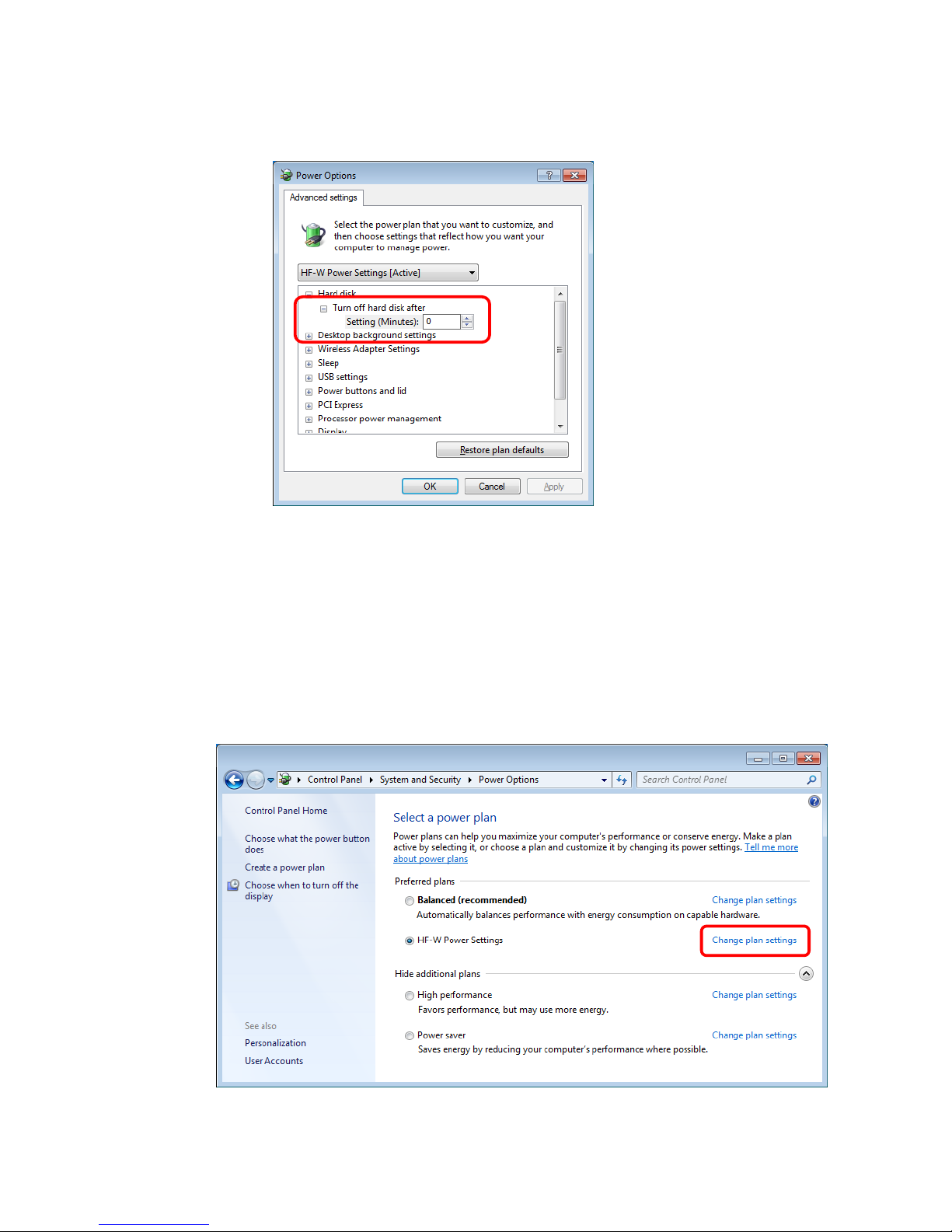
3. Advanced setting tab of Power Options appears.
・Confirm that Turn off hard disk after setting is "0".
When you change the settings from factory default setting, restore the factory default
setting following the procedure below.
1. Open Control Panel and click System and Security.
2. Click Power Options.
3. Power Options window appears.
・Confirm that HF-W Power Settings radio button is selected under Preferred
plans.

C-16
4. Edit Plan Settings window appears.
・Click Restore default settings for this plan.
5. Power Options window appears.
・Click Yes.

This Page Intentionally Left Blank

iv
CONTENTS
PREFACE .................................................................................................................... i
IMPORTANT NOTIFICATIONS ............................................................................ iii
SAFETY INSTRUCTIONS ............................................................................ S-1
PRECAUTIONS ..................................................................................................... C-1
CHAPTER 1 GETTING STARTED
.................................................................... 1-1
1.1 Scope .................................................................................................................................... 1-1
1.2 Installing an Extension Board .............................................................................................. 1-1
1.3 Role of an Operator .............................................................................................................. 1-1
1.4 Work Flow ........................................................................................................................... 1-3
1.5 Name and Function of Each Part ......................................................................................... 1-4
1.6 Installation Environment .................................................................................................... 1-13
1.6.1 Environment ................................................................................................................ 1-13
1.6.2 Installation ................................................................................................................... 1-14
1.7 Hardware connection ......................................................................................................... 1-17
1.8 Power cord ......................................................................................................................... 1-20
CHAPTER 2 OPERATION ................................................................................. 2-1
2.1 Before Turning On the Power .............................................................................................. 2-1
2.2 Starting the Equipment ......................................................................................................... 2-2
2.3 Shutting Down the Equipment ............................................................................................. 2-3
2.4 Power Shutdown .................................................................................................................. 2-4
2.5 Emergency Shutdown .......................................................................................................... 2-4
2.6 DVD drive ............................................................................................................................ 2-5
2.6.1 Inserting a CD or DVD .................................................................................................. 2-5
2.6.2 Ejecting a CD or DVD ................................................................................................... 2-6
2.6.3 Using the DVD drive when the equipment is installed vertically ................................. 2-6
2.7 Controlling the Power Using the LAN ................................................................................ 2-7
2.7.1 Enabling the WOL (Wake ON LAN) function .............................................................. 2-7
2.7.2 Turning on the power using the LAN ............................................................................ 2-8
2.8 Setting Up the LAN Interface ............................................................................................ 2-10
2.9 Setting Up the Screen ......................................................................................................... 2-22
CHAPTER 3 SETUP ............................................................................................ 3-1
3.1 Setup Procedure when you turn on the power for the first time ............................................ 3-1
3.1.1 Setting up Windows® 10 IoT ........................................................................................ 3-1
3.1.2 Setting up Windows® 7 ................................................................................................. 3-3
3.2 Configuring Basic Settings after OS Setup .......................................................................... 3-7
3.2.1 Basic Settings for Windows® 10 IoT ............................................................................ 3-7
3.2.2 Basic Settings for Windows® 7 .................................................................................. 3-12
3.2.3 Setup Procedure when using Windows XP Mode ....................................................... 3-18

v
CHAPTER 4 PRECAUTIONS WHILE THE OS IS RUNNING
....................... 4-1
4.1 Event Log Entries during Setup ........................................................................................... 4-1
4.2 Event Log Entries While the OS is Running ....................................................................... 4-2
4.3 Scheduled Functions by Default .......................................................................................... 4-4
4.4 Security Enhancement Function .......................................................................................... 4-12
4.5 Factory-Shipped Network Settings .................................................................................... 4-13
4.6 Drawing Abnormality Due to Frequent Use of Command Prompt ..................................... 4-14
4.7 STOP Error (0x7e) While Using File Sharing ..................................................................... 4-14
CHAPTER 5 SPECIFICATIONS
........................................................................ 5-1
5.1 Equipment Specifications .................................................................................................... 5-1
5.2 Memory Space ..................................................................................................................... 5-7
5.3 I/O Space .............................................................................................................................. 5-8
5.4 List of Interrupts .................................................................................................................. 5-9
5.5 Serial Port Settings ............................................................................................................. 5-10
5.6 BIOS Setup ........................................................................................................................ 5-11
5.7 Hardware System Clock ..................................................................................................... 5-16
5.8 Interface Specifications ...................................................................................................... 5-17
5.8.1 Connector specifications .............................................................................................. 5-17
5.8.2 External control specifications .................................................................................... 5-23
5.8.3 External interface cable length specifications ............................................................. 5-27
CHAPTER 6 CHECKUP AND MAINTENANCE ............................................. 6-1
6.1 Daily Checkup ...................................................................................................................... 6-1
6.2 Periodic Checkup ................................................................................................................. 6-4
6.3 Installing and Removing Components ................................................................................. 6-5
6.3.1 Types and locations of installed components ................................................................ 6-5
6.3.2 Before installing or removing components ...................................................................... 6-6
6.3.3 Installing and removing the cover of the equipment ..................................................... 6-7
6.3.4 Installing and removing an extension board .................................................................. 6-8
6.3.5 Installing and removing an external control board ...................................................... 6-12
6.3.6 Installing and removing a main memory ..................................................................... 6-15
6.3.7 Installing and removing an HDD or SSD .................................................................... 6-18
6.3.8 Installing and removing a DVD drive ......................................................................... 6-21
6.3.9 Installing and removing a dust filter ............................................................................ 6-22
6.3.10 Attaching and detaching the vertical stand ................................................................ 6-23
6.4 Removing the lithium battery ............................................................................................ 6-24
6.5 Enabling the Remote Power On Function .......................................................................... 6-26

vi
CHAPTER 7 RESTORING THE FACTORY-SHIPPED CONDITION USING
A RECOVERY DVD .................................................................... 7-1
7.1 Overview of Restoration Procedure ....................................................................................... 7-1
7.2 Preparation ........................................................................................................................... 7-2
7.3 Restoring the System Drive Back to the Factory-Shipped Condition ................................. 7-3
7.3.1 Procedure for restoring the system drive back to the factory-shipped condition .......... 7-3
7.3.2 Errors generated during a restoration process and their corrective actions ................. 7-13
CHAPTER 8 MAINTENANCE OPERATIONS ................................................. 8-1
8.1 Overview .............................................................................................................................. 8-1
8.2 Collecting a Memory Dump ................................................................................................ 8-6
8.2.1 Memory Dump Confirmation Messages ....................................................................... 8-8
8.2.2 Configuring the settings related to a memory dump ..................................................... 8-9
8.3 Startup Suppression on Serious Failure Detection ............................................................... 8-11
8.4 Maintenance Operation Commands ................................................................................... 8-12
8.4.1 Log information collection command (logsave) .......................................................... 8-13
8.4.2 Memory dump file copy command (mdump) .............................................................. 8-15
8.4.3 Disk area allocation command for saving a memory dump (createdmp) .................... 8-17
8.4.4 RAS information display command (getrasinfo) ......................................................... 8-19
CHAPTER 9 TROUBLESHOOTING ................................................................. 9-1
9.1 List of Problems ................................................................................................................... 9-1
9.1.1 Problems that occur before the OS startup .................................................................... 9-1
9.1.2 Problems that occur after the OS startup ....................................................................... 9-2
9.2 Countermeasures .................................................................................................................. 9-3
9.2.1 Problems that occur before the OS startup .................................................................... 9-3
9.2.2 Problems that occur after the OS startup ....................................................................... 9-7
9.3 STOP Error Codes ............................................................................................................. 9-19
9.4 Event Log ........................................................................................................................... 9-21
9.5 Checking the System Load by Using Performance Monitor ............................................. 9-27
9.6 Digital LED for Status indication ...................................................................................... 9-31
9.6.1 POST messages ........................................................................................................... 9-31
9.6.2 Displaying a hardware status code .............................................................................. 9-33

vii
CHAPTER 10 SOFTWARE RAID1
.................................................................. 10-1
10.1 Overview of Software RAID1 ......................................................................................... 10-1
10.1.1 What is software RAID1? .......................................................................................... 10-1
10.1.2 Functions of software RAID1 .................................................................................... 10-3
10.2 Setup ................................................................................................................................ 10-4
10.2.1 Overview of setup ...................................................................................................... 10-4
10.2.2 Newly setting up RAID1 ........................................................................................... 10-4
10.3 Checking the Status of the Software RAID1 ................................................................... 10-5
10.3.1 Checking by the Status Lamps .................................................................................. 10-5
10.3.2 Checking by the Hardware Status Window ............................................................... 10-6
10.3.3 Checking by the Software RAID1 utility .................................................................. 10-7
10.4 Recovery from Failure ..................................................................................................... 10-8
10.4.1 Detecting a failure ...................................................................................................... 10-8
10.4.2 Recovery from a failure in one HDD ........................................................................ 10-9
10.4.3 Recovery from power failure during operation of the system ................................. 10-17
10.4.4 When a problem occurs during recovery work ........................................................ 10-18
10.4.5 Recovery from Failure in Both HDDs ..................................................................... 10-19
10.4.6 Recovery a normal HDD that has been set to offline by mistake ............................ 10-19
10.5 Preventive Maintenance ................................................................................................... 10-20
10.5.1 Creating a Backup HDD .......................................................................................... 10-20
10.5.2 Recovery Using a Backup HDD .............................................................................. 10-22
10.5.3 Performing Periodical HDD Replacement .............................................................. 10-23
10.5.4 Data matching procedure ......................................................................................... 10-25
10.6 Software RAID1 Utility ................................................................................................... 10-26
10.6.1 Overview of software RAID utility ......................................................................... 10-26
10.6.2 Starting and exiting the software RAID utility .......................................................... 10-27
10.6.3 Status display function ............................................................................................. 10-29
10.6.4 Rebuilding function ................................................................................................. 10-30
10.6.5 Consistency check function ..................................................................................... 10-34
10.6.6 Array creation function .............................................................................................. 10-38
10.6.7 Drive initialization function ..................................................................................... 10-40
10.6.8 List of error message ............................................................................................... 10-43
APPENDIX HANDLING REPLACEABLE COMPONENTS .......................... A-1

viii
FIGURES
Figure 1-1 Name of Each Part (Front View) .............................................................................. 1-5
Figure 1-2 Name of Each Part (Rear View) ............................................................................... 1-6
Figure 1-3 Physical Configuration Inside Equipment ................................................................ 1-7
Figure 1-4 Operation and Service Clearance (Top View) ....................................................... 1-15
Figure 1-5 Installation Clearance ............................................................................................. 1-15
Figure 1-6 Exterior View (Horizontal Installation on the Desktop) ........................................ 1-16
Figure 1-7 Exterior View (Vertical Installation on the Desktop) ............................................ 1-16
Figure 1-8 Hardware Connection ............................................................................................. 1-18
Figure 2-1 DVD Drive (Front View) ......................................................................................... 2-5
Figure 6-1 Types and Locations of Installed Components ........................................................ 6-5
Figure 6-2 Removing the Cover of the Equipment .................................................................... 6-7
Figure 6-3 Removing the PCI Cover ......................................................................................... 6-9
Figure 6-4 Removing an extension board ................................................................................ 6-10
Figure 6-5 Installing an extension board .................................................................................. 6-11
Figure 6-6 Removing the FFC cable ........................................................................................ 6-13
Figure 6-7 Removing a main memory ..................................................................................... 6-16
Figure 6-8 Removing an HDD or SSD .................................................................................... 6-19
Figure 6-9 Removing a DVD drive .......................................................................................... 6-21
Figure 6-10 Removing a dust filter .......................................................................................... 6-22
Figure 6-11 Installing a dust filter ............................................................................................ 6-22
Figure 6-12 Attaching the vertical stand .................................................................................. 6-23
Figure 6-13 Removing the lithium battery ............................................................................... 6-24
Figure 6-14 Removing a Jumper Socket .................................................................................. 6-27

ix
TABLES
Table 1-1 Function of Each Part ................................................................................................ 1-8
Table 1-2 Dimension, Service Clearance, and Installation Clearance ..................................... 1-15
Table 1-3 Power Cord and Plug Identification ........................................................................ 1-21
Table 5-1 Hardware System Clock Specification .................................................................... 5-16
Table 8-1 Errors That Trigger a Memory Dump ....................................................................... 8-6
Table 8-2 Maintenance Operation Commands ........................................................................ 8-12
Table 8-3 Information Saved by logsave ................................................................................. 8-13
Table 8-4 Error Messages of the logsave Command ............................................................... 8-14
Table 8-5 Error Messages of the mdump Command ............................................................... 8-16
Table 8-6 Error Messages of the createdmp Command ........................................................... 8-18
Table 8-7 Information Displayed by the getrasinfo Command ............................................... 8-19
Table 8-8 Error Messages of the getrasinfo Command ........................................................... 8-27
Table 9-1 STOP Error Codes ................................................................................................... 9-19
Table 9-2 Action list for STOP Error Code 0x80 .................................................................... 9-20
Table 9-3 Event Log Entries Unique to the Equipment ........................................................... 9-23
Table 9-4 Performance Counters Related to the Performance of the Equipment .................... 9-29
Table 9-5 POST Codes and Stop Factor/Action ...................................................................... 9-31
Table 9-6 Hardware Status Code and Cause/Action ................................................................ 9-33
Table 10-1 Action list of when the Software RAID detected failure ....................................... 10-8
Table 10-2 Array Status and Drive Status ............................................................................. 10-29
Table 10-3 Error Messages from the Software RAID utility ................................................. 10-43

1. GETTING STARTED
1-1
CHAPTER 1 GETTING STARTED
1.1 Scope
This manual is intended for operators of the HITACHI INDUSTRIAL COMPUTER HF-
W2000 MODEL 48/45 and contains information about the operation and maintenance of
various devices necessary for their routine use.
After you unpack, go through the “delivered items list” to confirm all the items have been
delivered and no items are missing or damaged. If there are missing or damaged items,
contact our sales representative.
For information about RAS features, refer to the following manuals.
・ HF-W2000 MODEL 48/45 RAS FEATURES MANUAL (manual number WIN-63-0092)
1.2 Installing an Extension Board
You can install an extension board supplied by the user in this equipment.
For information about the installation procedure and the limitations of an extension board,
see “6.3.4 Installing and removing an extension board”.
1.3 Role of an Operator
In order to use this equipment in good working order for a long period of time, an operator
must take care of the following items.
(1) Setting up consumable items
(a) When you set up a consumable item (such as an HDD, or a dust filter), follow the device
operating procedure shown in the respective chapters.
(2) Consideration for the characteristics of the equipment
(a) See “PRECAUTIONS 1. PRECAUTIONS ABOUT THE EQUIPMENT” and take
necessary actions considering the characteristics of the equipment.
(b) The instructions described in this manual are the basics of the procedures you need to
follow when you use the equipment. Make sure you follow these instructions.
(c) For information about how to use the equipment, how to clean the equipment, and so on,
see the respective chapters.

1. GETTING STARTED
1-2
(3) Keep this equipment in good condition
When you use this equipment, an operator must take care of the following items.
(a) Backing up files
See “PRECAUTIONS 4. HARD DISKS DRIVES (HDDs) or SOLID STATE DRIVES
(SSDs) (2) Backing Up Files”.
(b) Power cord and shutting down the power
See “PRECAUTIONS 1. PRECAUTIONS ABOUT THE EQUIPMENT
(4) POWER SUPPLY”.
(4) Maintenance of this equipment
(a) For information about maintenance, see “6.1 Daily Checkup” and “6.2 Periodic
Checkup”.

1. GETTING STARTED
1-3
1.4 Work Flow
The following provides the work flow required until the equipment is turned on.
See “1.6 Installation Environment.”
See “1.7 Hardware connection.”
See “2.1 Before Turning On the Power.”
In case of installing an extension board,
see “6.3.4 Installing and removing an extension board.”
Unpack
Install this equipment
Install
extension boards
Turn on the power
Connect hardware

1. GETTING STARTED
1-4
1.5 Name and Function of Each Part
WARNING
Warning about the power supply unit (hazardous voltage)
Do not remove, disassemble, or modify the power supply unit. If you do, serious
personal injury or death may result due to an electric shock.
CAUTION
Cautions about the fans (rotating objects)
Only maintenance personnel are allowed to remove a fan. If you remove a fan
yourself, your hand or objects may be caught by the rotating part of the operating
fan and personal injury may result.
NOTICE
● Never hot-swap HDDs or SSDs because that may cause failure of the
equipment and HDDs or SSDs. Before you replace an HDD or SSD for the A
model or the S model, make sure you shut down the OS, unplug the power
cord from the outlet , and wait for at least one minute.
● When using a USB port, check the orientation of the USB connector, and then
insert the connector slowly. Otherwise, the USB port may be damaged.
● Do not remove or insert a USB device during online operation (system
operation) because that may affect currently running applications.
● If you insert or access a CD or DVD, the system load may increase and
running applications may be affected. Do not insert or access an optical disc
during online operation (system operation).

1. GETTING STARTED
1-5
● Display and User Input Sections
(1) Front view
(*1) Press the reset switch by inserting an eject pin. If an eject pin is not available, use a pin that
fits the hole of the reset switch instead.
Figure 1-1 Name of Each Part (Front View)
The dimensions do not
include rubber feet.
Reset switch(*1)
Front USB2.0 port
Status lamp (STATUS)
Alarm lamp
Drive access lamp /
Standby lamp (STBY)
Power switch
HDD2 Status lamp
HDD1 Status lamp
93mm
325mm
356mm
Front USB3.0 port
Status display digital LEDs

1. GETTING STARTED
1-6
(2) Rear view
(*1)
If a display unit connected with DisplayPort is turned off, the display cannot be detected.
(*2)
PCI Express x16 connectors is used but the internal connection is equivalent to PCI Express x4.
Figure 1-2 Name of Each Part (Rear View)
AC inlet
USB3.0 port
(4 port)
Serial port
(COM1)
Audio port
Upper
:
LINE IN
Lower
:
LINE OUT
DVI-I port
DVI-D port
1
Slot1:PCI
ACT/LINK lamp
Communication speed lamp
LAN port:
1000BASE-T/100BASE-TX/10BASE-T
Extension slots
DisplayPort(*1)
2
3
Slot2:PCI Express x4 (*2)
Slot3:PCI Express x16
・Left side :LAN1
・Right side:LAN2

1. GETTING STARTED
1-7
(3) Physical configuration inside the equipment
Figure 1-3 Physical Configuration Inside Equipment
CPU fan
(installed inside the equipment)
Motherboar
d
Power supply unit
DVD Drive
Drive bay 2
Drive bay 1
PS fan
System fan

1. GETTING STARTED
1-8
Table 1-1 Function of Each Part (1/5)
Name Function
Power switch (POWER) When you press this switch, the power is turned on. When you press the
switch for four seconds or more, the power is turned off and the system
goes into standby mode (for emergencies only).
Reset switch (RESET) Use this switch to perform a hardware reset (restarting the equipment).
If you press the switch while the OS is running, a memory dump is
performed. If you press the switch again after the memory dump is
performed, a hardware reset is carried out.
Status lamp (STATUS)
Lamp Status
Lit in green The equipment is in operation (RUN status)
Lit in red The equipment is not in operation (STOP status)
• The equipment is in the middle of startup.
• After the shutdown starts or during error stop.
• The equipment has stopped abnormally due to an
error
• RAS software is not installed.
Off The main power is off / The system is in standby mode.
Alarm lamp (ALARM) This lamp is lit in red if one of the following abnormalities is detected.
• A fan inside the equipment stops.
• Abnormal temperature inside the equipment.
• Failure in one of the mirrored disks. (B model only)
Drive access lamp
(DRIVE)
This lamp is lit in green while an HDD, SSD or DVD drive is being
accessed.
Standby lamp (STBY)
Lamp Status
Lit in
orange
The equipment is in standby mode. (Only the auxiliary
power is on.)
Off The power is shut down or the equipment is in
operation.
HDD status lamp
HDD1 STATUS:
For drive bay 1
HDD2 STATUS:
For drive bay 2
(B model only)
Lamp Status
Off One HDD are working properly.
Lit in red One HDD has an error. (The power of the HDD with an
error is Off.)
Flashed in
red
(Either one)
Rebuild (copy) is ongoing. Only the lamp of the copy
destination HDD flashes.
Flashed in
red (Both)
Both HDDs have errors.

1. GETTING STARTED
1-9
Table 1-1 Function of Each Part (2/5)
Name Function
AC inlet Used for connecting a power cord.
Power supply A power supply module with a wide-range input voltage (100 to 240
VAC).
Audio port (LINE IN) An audio line input.
Audio port (LINE OUT) An audio line output.
Serial port (COM1)
(9 pins: RS-232C)
You can use this connector to connect a device such as a modem that uses
a serial interface.
(See “5.8.1 Connector specifications”.)
Serial port (COM2)
(9 pins: RS-232C)
(optional)
Connects a device such as a modem that uses a serial interface.
(See “5.8.1 Connector specifications”.)
RAS external contact port
(25 pins: EXT)
(optional)
A connector for connecting external contacts. (See “5.8.1 Connector
specifications”.)
DVI-I port (*1)
Connects the cable from the digital interface of a display. (See “5.8.1
Connector specifications”.)
DVI-D port Connects the cable from the digital interface of a display. (See “5.8.1
Connector specifications”.)
DisplayPort Connects the cable from the digital interface of a display. (See “5.8.1
Connector specifications”.)
PCI bus slot Used as a slot to insert a PCI board.
PCI Express x16 bus slot Used as a slot to insert a PCI Express x16 board.
PCI Express x4 bus slot Used as a slot to insert a PCI Express x4 board. But the connector is a PCI
Express x16 connector.
PCI Express x1 bus slot Used as a slot to insert a PCI Express x1 board.
USB port (USB2.0/USB3.0) Used to connect a device that uses a USB interface.
(*1) By using a conversion connector or DVI-A cable, you can output an analog VGA signal. The
conversion connector or DVI-A cable must be provided by the user.

1. GETTING STARTED
1-10
Table 1-1 Function of Each Part (3/5)
Name Function
LAN port
(1000BASE-T/100BASE-TX/
10BASE-T)
You can connect a LAN cable to a LAN port. (See “5.8.1 Connecto
r
specification”.)
Onboard LAN
ACT/LINK lamp
Lamp Status
Lit in green A link is established.
Both the equipment and the remote device are powered
up and the connection over the twisted-pair Ethernet
cable is stable.
Off No link is established.
• The equipment is not physically connected to the
network.
• The switching hub is not powered up.
• The connection over the twisted-pair Ethernet cable is
not stable.
• The driver settings have some errors.
Blinking in
green
Network data is being transmitted or received.
The blink interval changes depending on the traffic on
the network.
Communication speed lamp
Lamp Status
Lit in
orange
The link is established at1000 Mbps.
Lit in green The link is established at 100 Mbps.
Off The link is established at 10 Mbps. Or no link is
established.
Communication speed lamp
ACT/LINK lamp

1. GETTING STARTED
1-11
Table 1-1 Function of Each Part (4/5)
Name Function
LAN port
(1000BASE-T/100BASE-TX/
10BASE-T)
Option LAN adaptor(HJ-F2040-20)
/
Option LAN adaptor (HJ-F2040-21)
ACT/LINK lamp
Lamp Status
Lit in green A link is established.
Both the equipment and the remote device are powered
up and the connection over the twisted-pair Ethernet
cable is stable.
Off No link is established.
• The equipment is not physically connected to the
network.
• The switching hub is not powered up.
• The connection over the twisted-pair Ethernet cable is
not stable.
• The driver settings have some errors.
Blinking in
green
Network data is being transmitted or received.
The blink interval changes depending on the traffic on
the network.
Communication speed lamp
Lamp Status
Lit in
orange
The link is established at 1000 Mbps.
Lit in green The link is established at 100 Mbps.
Off The link is established at 10 Mbps. Or no link is
established.
(Note) The locations of ACT/LINK lamp and transmission rate lamp differ between the optional LAN adapter onboard
LAN.
Communication speed lamp
ACT/LINK lamp

1. GETTING STARTED
1-12
Table 1-1 Function of Each Part (5/5)
Name Function
Digital LED for
Status indication
Various states of this equipment are indicated as a two-digit code in
hexadecimal and the states of the status indication LEDs.
The Digital LED for Status indication and the status indication LEDs may
remain lit even after the equipment is shut down or put into standby mode.
This condition remains until the power is turned on again.
Status indication LEDs
[1] Hardware status (Red)
[2] Application status (Green)
[3] BIOS status (Orange)
(For information about how to display arbitrary status data on the Digital
LED for Status indication from a user application, refer to the “HF-W2000
Model 48/45 RAS FEATURES MANUAL”.)
Status indication LEDs
① ② ③
< NOTE >
・ For information about the precautions for USB devices,
see “PRECAUTIONS 6. USB DEVICES”.
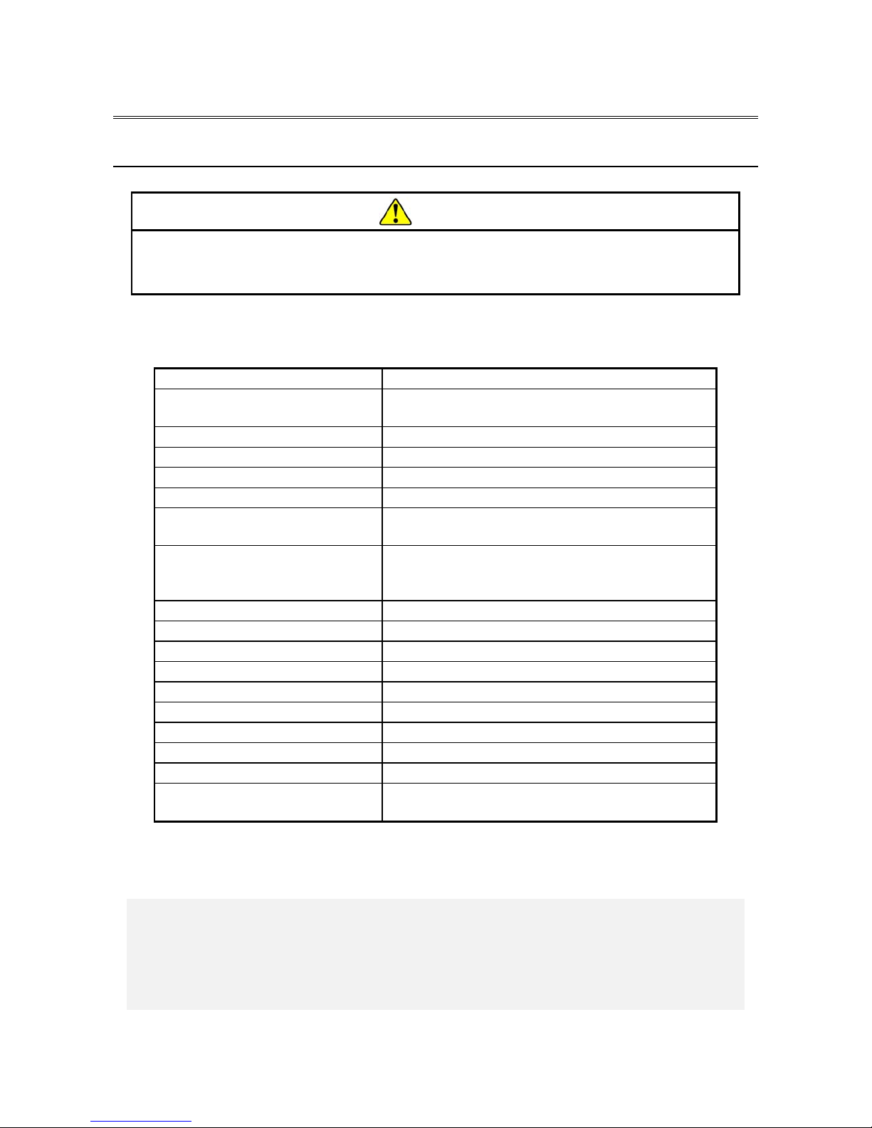
1. GETTING STARTED
1-13
1.6 Installation Environment
1.6.1 Environment
CAUTION
If you keep at high temperature this equipment, do not touch bare hands.
Otherwise you may result burns.
When this equipment is used, it must be used in the following environment.
Item Requirement
Ambient temperature (Operation) Model 48: 5 to 35℃
Model 45: 5 to 40℃
Ambient temperature (Storage) -10 to 60℃
Temperature gradient ±10 K/h or less
Humidity 20 to 80%RH (non-condensing)
Humidity gradient ± 10% RH/h or less
Dust (*1) No heavy dust
(0.3 mg/m
3
or less (JEITA IT-1004A classB))
Corrosive gas None
JEITA IT-1004A class A (Temperature 25℃,
Humidity 50% RH)(*2)
Vibration resistance 5.9 m/s2 (10 Hz, 5 s, except the DVD drive)
Shock resistance Operation: 19.6 m/s2 (while not powered on: 98 m/s2)
Power voltage 100 to 240 VAC ± 10%
Power frequency 50/60 Hz ± 3 Hz
Power supply noise 2.0 kV (fast transient / burst wave)
Electrostatic noise contact discharge 4 kV (Air: 8 kV)
Insulation resistance 500 VDC, 20 MΩ
Dielectric strength 1.5 kVAC, one minute
Transient power fault 20 ms or less
Altitude Model 48: Less than 1000 m
Model 45: Less than 2000 m
(*1) This equipment cannot be used in the environment where conductive dust or the like is
floating.
(*2) JEITA:Japan Electronics and Information Technology Industries Association
< NOTE >
・ For information about the precautions for the environment, see
“PRECAUTIONS 1. PRECAUTIONS ABOUT THE EQUIPMENT
(5) INSTALLATION ENVIRONMENT”.

1. GETTING STARTED
1-14
1.6.2 Installation
WARNING
The power cord that comes with the equipment is rated at the input voltage of
125 VAC. When using this equipment at over 125 VAC, prepare the power cord
fitting input voltage and inspect the safeness of this equipment enough.
When you connect the plug of the power cord to an outlet, make sure you use
an outlet with a ground terminal (ground pole) that is properly grounded. In
addition, you must install and use an earth leakage circuit breaker.
If you do not take these measures, that may result in a fire or an electric shock.
Do not use a two-prong plug without a ground pole because that may result in
an electric shock or failure of the equipment.
CAUTION
Falling or dropping of the Equipment vertically placed on the desktop may cause
injury. Be sure to attach the vertical stand accompanying the Equipment and
place the Equipment with the vertical stand on a level surface.
NOTICE
Before you move this equipment, make sure you shut down the OS, disconnect
the plug of the power cord from the outlet, and wait for at least one minute.
If you do not, the HDDs and other devices may fail.
When you transport or carry the equipment, pack it in the dedicated container
(container and packing materials used when the equipment was delivered). If
you use other container or packing materials, that may damage the equipment.
Do not use damaged or broken dedicated container when you transport or
carry the equipment. If you do, that may damage the equipment.
< NOTE >
・For information about the precautions for concerning installation requirements,
see “PRECAUTIONS 1. PRECAUTIONS ABOUT THE EQUIPMENT (5)
INSTALLATION ENVIRONMENT”.

1. GETTING STARTED
1-15
Table 1-2 Dimension, Service Clearance, and Installation Clearance
Dimension (mm)
Operation and
service clearance (mm)
Installation clearance (mm)
Height Width Depth Front Rear Left Right Front Rear Left Right
93 325 356
500 600 200 200 50 100 10 10
・When you operate the equipment or do maintenance work, provide sufficient clearance
as shown in Figure 1-1.
・The equipment is air-cooled by fans. The intake holes are on the front and the exhaust
holes are on the rear. Make sure the air flow is not blocked. Especially, leave sufficient
clearance in the front (50 mm) and in the rear (100mm). (This includes clearance required
for routing cable connectors for the rear side.)
Figure 1-4 Operation and Service Clearance (Top View)
Figure 1-5 Installation Clearance
200 mm 200 mm
Front side
Rear side
600 mm
500 mm
Vertical Installation (Top View)
100 mm
50 mm
10 mm
10 mm
Front side
Rear side
Horizontal Installation (Top View)
100 mm
10 mm
50 mm
10 mm
Front side
Rear side

1. GETTING STARTED
1-16
(a) Horizontal Installation
Figure 1-6 Exterior View (Horizontal Installation on the Desktop)
(b) Vertical Installation
Figure 1-7 Exterior View (Vertical Installation on the Desktop)

1. GETTING STARTED
1-17
1.7 Hardware connection
NOTICE
Do not route the interface cables, etc. (including cables for other devices such
as a PC) near the power cord. If you do, a failure or malfunction of the
equipment may result.
Do not connect or disconnect an interface cable while the power for this
equipment or for the remote device is on. If you do, failure of the equipment
may result due to a short circuit between the power supply and the ground.
When an interface cable comes off while the power for the equipment is on,
shut down the OS and disconnect the power cord from the outlet.
Disconnecting the power cord from the outlet without shutting down the OS
might destroy the internal files.
When you connect a cable for external contacts, make sure you connect the
cable to a connector for the external contacts (EXT). It is possible that a
voltage as high as 40 VDC can be applied to the cable through a relay load.
If you connect the cable to the wrong connector, that may cause failure of the
equipment.
Before you connect hardware, carefully read SAFETY INSTRUCTIONS in this document and
fully understand the contents.

1. GETTING STARTED
1-18
Connect hardware based on the connection example shown in the figure below.
Connect the display, keyboard, and mouse to this equipment and then insert the plug of the
power cord into an outlet.
Figure 1-8 Hardware Connection
(*1) For information about the naming of the user input module and how to operate and adjust the
device, refer to the user’s manual that comes with the device.
(*2) For information about the length of each connection cable, see “5.8.3 External interface cable
length”. The mouse and keyboard connection cables must be directly connected to this
equipment. Do not use extension cables for them. If you use extension cables, the mouse or
keyboard may not work properly.
(*3) When you connect USB devices to the USB connectors, pay attention to the orientation of the
connector. In addition, in the USB port, a USB cable may fall out from the connector by the
unexpected contact because there is not the locking mechanism of the connector in a standard.
When you install this equipment, fix USB cables if it is necessary.
(Note)
In order to conformity the EMC standards (VCCI, FCC, CE), use shielded cables for the
interface cables (display interface cable, keyboard interface cable, and mouse interface cable)
connected to the equipment.
Mouse
Display
(*1)
Keyboard
(the equipment connection side)
Power cord for this equipment
Display
p
ower cord
Display interface cable (*2)
Keyboard interface cable (*2)
Mouse interface cable (*2)
USB3.0 port (*2) (*3)

1. GETTING STARTED
1-19
Connecting to an outlet
Fully and securely insert the plug of the power cord of this equipment into an outlet with
a grounding pole that is properly grounded. (*1)
(*1) If you have no other choice than to use an outlet without a grounding pole that is
properly grounded, use 3-pole to 2-pole conversion adapter and connect the green
ground line from the adapter to the ground of the outlet. A user must verify the proper
functionality of the 3-pole to 2-pole conversion adapter before using it.
Make sure you use a power cord with a
2-pole plug with a grounding pole.
< NOTE >
• The power cord that comes with the equipment is rated at the input voltage of
125 VAC. When using this equipment at over 125 VAC, prepare the power cord
fitting input voltage.
•
If you use a power cord clamp for preventing accidental disconnection, add an
extra length to the power cord around the connector when you secure the cord,
in order to allow the cord to be disconnected in an emergency. Alternatively,
install an emergency circuit breaker at the outlet side.

1. GETTING STARTED
1-20
1.8 Power cord
CAUTION
When procuring an AC power cord, make sure that the cord has proper rating
and meets local safety requirements whatever applicable. Otherwise, an electric
shock or machine failure may result.
The power cord that comes with the equipment is rated at the input voltage of 125VAC.
When using this equipment at over 125VAC, prepare the power cord fitting input voltage and
inspect the safeness of this equipment enough. Common power cords are shown in Table 1-3.
1 ANSI: American National Standards Institute
2 NEMA: National Electrical Manufacture’s Association
3 IEC: International Electrotechnical Commission
4 CEE: International Commission on Rules for the Approval of Electrical Equipment
5 BS: British Standard Institution
6 AS: Standards Association of Australia
7 GB:国家标准(Guójiā Biāozhǔn)

1. GETTING STARTED
1-21
Table 1-3 Power Cord and Plug Identification
Input rating Plug configuration
Reference
standards
Cord and connector
100V - 120V
North America
1 ANSI C73.11
2 NEMA 5-15P
3 IEC 83
125V
North America
1 ANSI C73.11
2 NEMA 5-15P
3 IEC C13
200V - 240V
North America
1 ANSI C73.11
2 NEMA 6-15P
3 IEC 83
Three-wire power cord
with a two-pole threeterminal grounding-type
connector.
Universal Euro
4 CEE (7)
II, IV, VII
3 IEC 83
UK
5 BS 1365
3 IEC 83
Australia
6 AS C112
220V – 250V
中华人民共和国
7 GB/T 5023.5
GB 1002,
GB 2099.1
GB 17465.1
GB 15934
< NOTE >
• As an option, this equipment offers a cable clamp to be used for attaching the
power cord to the equipment. Use that cable clamp as required.
a
c
23 mm
a=7±0.05 mm
b=7±0.05 mm
c=15.8 mm
b
电源线请务必使用带
接地相的3相插头。

This Page Intentionally Left Blank

2. OPERATION
2-1
CHAPTER 2 OPERATION
2.1 Before Turning On the Power
WARNING
If any of the air intake and exhaust holes of the equipment is blocked, the
temperature inside the equipment may rise and that may cause a fire or failure of
the equipment. Make sure sufficient clearance is provided around the equipment
when you install. (See “1.6.2 Installation”.)
< NOTE >
When you turn on the power, see the following:
・ “PRECAUTIONS 1. PRECAUTIONS ABOUT THE EQUIPMENT
(2) INTERFACE CABLES
・ “PRECAUTIONS 1. PRECAUTIONS ABOUT THE EQUIPMENT
(4) POWER SUPPLY”
・ “PRECAUTIONS 1. PRECAUTIONS ABOUT THE EQUIPMENT
(5) INSTALLATION ENVIRONMENT”

2. OPERATION
2-2
2.2 Starting the Equipment
Follow the procedure below to start the equipment:
1. Connect the plug of the power cord to the outlet.
When the plug of the power cord is connected to the outlet, the standby lamp (STBY)
will be turned on.
2. Turn on the power to the display.
3. Press the power switch. (See “1.5 Name and Function of Each Part”.)
When the power is turned on, the standby lamp (STBY) is turned off and the status
lamp (STATUS) will light. The status lamp turns “red” when the power is turned on
and turns “green” when the OS starts and the equipment is in operation.
4. After the OS starts, set up the equipment according to “3.1 Setup Procedure When
You Turn On the Power for the First Time”. (You need to follow this procedure only
once for the first time when you start the equipment after you purchase the equipment.)
After the above steps are complete, the equipment automatically goes through the startup
process until the sign in screen appears.
For information about how to control the power using the LAN, see “2.7 Controlling the
Power Using the LAN”.
< NOTE >
・When the RAS software is not installed or during the recovery process, the
status lamp does not turn green and stays red.

2. OPERATION
2-3
2.3 Shutting Down the Equipment
When you shut down the equipment, first confirm that no other users are using the equipment and
no background programs are running. Then follow the procedure below:
・Stop application programs.
・Shut down the OS.
The specific procedure for stopping an application program differs depending on each
application. For more information, see the manual of each application.
<If the OS is Windows® 10 IoT Enterprise >
To shut down the OS, click the Start button at the left bottom corner of the screen and open the
start menu. Then click Power and click Shut down. After the OS is shut down, the power is
automatically turned off and only the auxiliary power supply is on (standby mode). (In this mode,
the status lamp (STATUS) is off and the standby lamp (STBY) is on.)
<If the OS is Windows® 7 Professional>
To shut down the OS, click the Start button at the left bottom corner of the screen and click Shut
down. After the OS is shut down, the power is automatically turned off and only the auxiliary
power supply is on (standby mode). (In this mode, the status lamp (STATUS) is off and the standby
lamp (STBY) is on.)
If the normal shutdown process cannot be executed (for example, a shutdown request cannot be
accepted due to system deadlock), open the protective cover on the right upper part of the front
panel and press the power switch for at least four seconds. The power is turned off and the
equipment goes into the standby mode. If you turn off the power by pressing the power switch for at
least four seconds, you cannot turn on the power by way of the LAN next time. Do not turn off the
power this way except for emergencies. (See “2.7 Controlling the Power Using the LAN”.) For
information about how to collect a memory dump, see “8.2 Collecting a Memory Dump”.
2. OPERATION
2-4
2.4 Power Shutdown
1. Confirm that the equipment is shut down. (See “2.3 Shutting Down the Equipment”.)
2. Remove the plug of the power cord of this equipment from the outlet.
3. When the main power is turned off, the standby lamp (STBY) is turned off.
2.5 Emergency Shutdown
WARNING
In case of smoke, a burning smell, or the like, unplug the power cord from the
outlet, and contact your dealer or maintenance personnel. Using faulty
equipment without repair may result in a fire or an electric shock.
NOTICE
● Performing emergency shutdown (that is, unplugging the power cord from the
outlet or shutting off the breaker without proper shutdown of the OS) may
cause the OS or applications not to work properly or may cause saved data to
be corrupted. Do not perform emergency shutdown unless you must stop the
system immediately due to some kind of error.
● If you turn off the power at the source of AC the power, the system may not be
able to recover automatically.
In the following cases, turn off the power at the source of the AC power.
・When the equipment shows an error condition and you have to shut down the power
immediately (for example, when a burning smell is detected).
・When you cannot shut down the equipment due to some error.
・When the power is turned off repeatedly or only the auxiliary power supply is on due to
excess current or overheating.
In the following cases, remove the plug of power cord of this equipment from the outlet or
turn off the power at the source of the AC power.
・If the fan is stopped and the temperature gets too high or too low and consequently the
power is automatically turned off to protect the equipment and only the auxiliary power
supply is on.
Before the OS starts, the BIOS can detect a stopped fan during BIOS start up and if
detected, the power is automatically turned off.
After the OS starts, when a stopped fan is detected, the OS is automatically shut down
and then the power is turned off
(When already RAS was installed).

2. OPERATION
2-5
2.6 DVD drive
NOTICE
● If you insert or access a CD or DVD, the system load may increase and
running applications may be affected. Do not insert or access an optical disc
during online operation (system operation).
● When you finish accessing a CD or DVD, eject the disc from the DVD drive.
If you leave the disc in the DVD drive, failure may result.
● If you keep the disc tray open, failure may result.
When you do not intend to use the DVD drive, keep the disc tray inside the
DVD drive.
● Do not use an unbalanced CD or DVD due to attached labels and so on; a disc
with cracks, scratches, or vertical deviation; or a disc with a non-standard
shape. If you do, an abnormal sound or vibration may be generated and failure
of the equipment may result.
2.6.1 Inserting a CD or DVD
1. Press the eject button gently to open the disc tray.
2. Set the CD or DVD on the disc tray with the label side facing up.
3. Push the disc tray to load the disc into the DVD drive.
Front View When the Disc Tray Is Open
Front View of the DVD Drive
Figure 2-1 DVD Drive (Front View)
Disc
Lamp
Eject button
Manual emergency
eject hole

2. OPERATION
2-6
2.6.2 Ejecting a CD or DVD
1. Confirm that the lamp is neither on nor flashing (the drive is operating).
2. Press the eject button gently to open the disc tray.
3. Pick up the CD or DVD.
2.6.3 Using the DVD drive when the equipment is installed vertically
1. Press the eject button to eject the disc tray from the DVD drive.
2. While holding the disc tray with your left hand, set a CD or DVD on the disc tray with
your right hand.
3. Remove your left hand from the disc tray.
4. Push the disc tray to load the disc into the DVD drive.
5. When you remove the CD or DVD, pull out the disc without applying excessive force to
the disc.
< NOTE >
・ For information about the precautions for the DVD drive, see “PRECAUTIONS
5. DVDs”.
< NOTE >
・ When you are writing to a CD or DVD, use the OS to eject the disc. If you press
the eject button, writing to the disc may fail.

2. OPERATION
2-7
2.7 Controlling the Power Using the LAN
The power for this equipment can be turned on from a remote device by way of the LAN.
This section explains WOL (Wake ON LAN), which is used for turning on the power for
the equipment through the LAN. When the power is turned on by using WOL, the equipment
is started by sending a Magic Packet™ frame to the LAN interface when the standby lamp
(STBY) is on.
In the initial factory settings, this function is disabled. If you want to use this function,
follow steps 1 through 3 described in “2.7.1 Enabling the WOL (Wake ON LAN) function”
to enable the WOL function and then follow the steps below.
2.7.1 Enabling the WOL (Wake ON LAN) function
By following the procedure below, you can set up whether to start WOL when a Magic
Packet™ frame is received. In the initial factory settings, the WOL function is disabled.
(The display image assumes Windows® 10 IoT but it is similar under other OS.)
1. Execute steps 1 though 5 in “● Setting up the network transfer speed” in “2.8 Setting
Up the LAN Interface”.
2. Click the Power Management tab. If you want to enable WOL, select the Wake on
Magic Packet from power off state check box under Wake on LAN :.
3. Click OK and restart the system.
< NOTE >
・ For information about the precautions for the network, see “PRECAUTIONS 2.
NETWORK”.

2. OPERATION
2-8
2.7.2 Turning on the power using the LAN
1. Insert the plug of the power cord into an outlet and turn on the main power. The standby
lamp (STBY) will be lit.
2. Send a Magic Packet™ frame to the built-in LAN adapter in the equipment. When the
built-in LAN adapter receives a Magic Packet™ frame, the power for the equipment is
turned on.
You must turn on the standby lamp (STBY) in order to start the equipment through the
LAN (using WOL). If you start the equipment and you want to continue to use WOL at the
next startup, go through the shutdown process when you turn off the power.
The built-in LAN adapter in the equipment is compliant with WfM 2.0 (*1) to support
the Magic Packet™ technology. Because of this, the power for the equipment can be turned
on when a special data packet called a “Magic Packet™ frame” (*2) is received at the built-
in LAN adapter.
A program for transmitting a Magic Packet™ frame does not come with the equipment.
Use a commercially available program for to transmit the Magic Packet™ frame.
(*1) Wired for Management (WfM) is a guideline regarding the hardware specifications
proposed by Intel Corporation for managing PCs on a network.
(*2) The Magic Packet™ technology has been proposed by AMD Japan, Ltd. and can be
starting a PC on a network from a remote device.
< NOTE >
・ When you send a Magic Packet™ frame to the equipment, make sure you
send it to the built-in LAN adapter in the equipment. (For information about the
location of the connector, see “1.5 Name and Function of Each Part”.) You
cannot use WOL if you send a Magic Packet™ frame to an optional LAN
adapter.
・ If you turn off the power by pressing the power switch for at least four seconds,
you cannot use WOL the next time. When you turn off the power by pressing
the power switch for at least four seconds, turn on the equipment by pressing
the power switch and go through the shutdown process to turn off the power.

2. OPERATION
2-9
< About the Magic Packet™ frame >
In a Magic Packet™ frame, the SOURCE ADDRESS, DESTINATION ADDRESS (the
MAC address of the receiver or the MULTICAST ADDRESS including the BROADCAST
ADDRESS), CRC, and the like must meet the basic requirements of the LAN in use. The data
in a Magic Packet™ frame consists of a sequence of 16 repetitions of the MAC address of the
node. This sequence can be anywhere in the packet but it must follow a synchronization stream.
The synchronization stream is defined as 6 bytes of 0xFF. As long as the MAC address that
repeats itself 16 times targets the address of the equipment to be started, the device can receive a
BROADCAST frame.
A Magic Packet™ frame is shown in the following figure.
DA SA Arbitrary
data
FF…FF Adr … Adr Adr Arbitrary
data
CRC
16 repetitions of the MAC
address
Synchronization stream
(6 bytes of 0xFF)
Source Address
Destination Address

2. OPERATION
2-10
2.8 Setting Up the LAN Interface
This equipment has two built-in 1000BASE-T/100BASE-TX/10BASE-T LAN ports. For
information about the location of the LAN port connector (1000BASE-T/100BASE-
TX/10BASE-T), see “1.5 Name and Function of Each Part”.
● Automatic recognition of the network transfer speed or transfer mode
The LAN port has an auto-negotiation function to automatically recognize the network
transfer speed or transfer mode. For normal use, enable the auto-negotiation function.
(Especially when you use the WOL function. If the speed is fixed to 1000Mbps (auto-
negotiation), the WOL function cannot be used.)
If there is a compatibility issue with the connected hub, the auto-negotiation function may
not work properly and that may affect the communication with other terminals.
If the auto-negotiation function does not work properly, configure the LAN interface as
follows.
Specification of
the hub
Specification of the LAN setting (*)
Speed Duplex
10 Mbps / Half-
duplex
10 Mbps Half Duplex
10 Mbps / Full-
duplex
10 Mbps Full Duplex
100 Mbps / Half-
duplex
100 Mbps Half Duplex
100 Mbps / Full-
duplex
100 Mbps Full Duplex
1000 Mbps 1000 Mbps (1.0 Gbps)
Auto Negotiation or
Full Duplex
(*) How the setting is displayed is different depending on the OS and the
LAN port (including the optional LAN adapter) in use.
< NOTE >
・ For information about the precautions for the network, see “PRECAUTIONS 2.
NETWORK”.

2. OPERATION
2-11
● Setting the network transfer speed
(The display image assumes Windows® 7 but it is similar under other OS.)
1. Log on to the computer using an administrator's account.
2. Right-click Start. Then click Device Manager. The Device Manager window appears.
(In Windows® 7, click Start > Control Panel > System and Security > System >
Device Manager. Then go to step 3.)
3. Click the View menu and select Devices by connection.

2. OPERATION
2-12
4. Click ACPI x64-based PC > Microsoft ACPI-Compliant System > PCI Express Root
Complex.

2. OPERATION
2-13
5. See the following and double-click the network adapter you want to configure and open
Network Connection Properties window.
[When you configure the built-in LAN (LAN1)]
Click Intel(R) 8 Series/C220 Series PCI Express Root Port #3 – 8C14.
Then double-click the network adapter under it (in the example in the figure below,
Intel(R) I210 Gigabit Network Connection).
[When you configure the built-in LAN (LAN2)]
Click Intel(R) 8 Series/C220 Series PCI Express Root Port #4 – 8C16.
Then double-click the network adapter under it (in the example in the figure below,
Intel(R) I210 Gigabit Network Connection#2).
Follow a similar procedure when you update the setting for the network adapter mounted
on an extension slot.
(*1)上記の表示名は、ご使用のOSやLANドライバのバージョンによって異なります。

2. OPERATION
2-14
6. Click the Link Speed tab.
7. Select the transfer speed and the transfer mode you want to choose from the Speed and
Duplex list.
・Auto Negotiation: auto-negotiation setting
・10 Mbps Half Duplex: 10 Mbps/Half-duplex setting
・10 Mbps Full Duplex: 10 Mbps/Full-duplex setting
・100 Mbps Half Duplex: 100 Mbps/Half-duplex setting
・100 Mbps Full Duplex: 100 Mbps/Full-duplex setting
・1.0 Gbps Full Duplex: 1.0 Gbps/Full-duplex setting

2. OPERATION
2-15
If you do not have to configure the transfer speed and the transfer mode, select Auto
Negotiation at the top of the list to choose the auto-negotiation setting.
8. Click OK.
9. Close the Device Manager window.
< NOTE >
・ For information about the precautions for the network, see “PRECAUTIONS 2.
NETWORK”.

2. OPERATION
2-16
Action to take if the link is unstable at 1000 Mbps
Depending on the type of the connected hub, the link may not be stable at 1000 Mbps. If
you want to use the network at 1000 Mbps, verify the connection with the hub in advance.
If the link is unstable at 1000 Mbps, it is made stable by taking the following action.
• Use a cable which is 20 to 100 meters long (UTP Category 5e or better).
• Fix the master/slave mode setting to Master (valid only in the 1000Mbps setting).
Follow the procedure below to fix the mater/slave mode to Master. The link may not
function depending on the type of the hub. In this case, re-set the setting to Auto Detect.
1. Execute steps 1 though 5 in “ Setting the network transfer speed” in “2.8 Setting Up the
LAN Interface”.
2. Click the Advanced tab. Select Gigabit Master/Slave Mode from the Settings list.
3. From the Value pull-down menu, select Force Master Mode.
4. Click OK and restart the equipment.

2. OPERATION
2-17
Precautions for mounting and using multiple LAN adapters
If multiple LAN adapters are mounted and there are frequent interrupt requests from either
of the adapters or the amount of processed data is too large, the performance of the adapters
may not be as high as expected. (This is because an interrupt request from a LAN adapter
requires a higher CPU load compared to the amount of processed data and if multiple LAN
adapters are mounted and used, it takes a very long time for the CPU to process all interrupt
requests from the LAN adapters.)
If you mount and use multiple LAN adapters, confirm that each built-in LAN adapter and
optional adapter can perform as expected. If they do not, adjust the network load or change the
LAN adapter settings by following the procedure below. For details about each configuration
item, see the description at the bottom of the corresponding setup window.
(The display image assumes Windows® 10 IoT but it is similar under other OS.)
1. Execute steps 1 though 5 in “● Setting the network transfer speed” in “2.8 Setting Up
the LAN Interface”.
2. Click the Advanced tab. Select Performance Options and click Properties.
The Performance Options dialog box is displayed.

2. OPERATION
2-18
・DMA Coalescing
Sets an upper limit on the maximum amount of latency applied to any network packet due to direct Memory
Access(DMA) Coalescing.
・Flow Control
This enables adapters to generate or respond to flow control frames, which help regulate
network traffic. The default setting of the flow control is different depending on the OS
and the type of LAN adapter in use. You must configure the flow control setting according
to the network you are using.
< NOTE >
・ If the LAN driver stops due to a system failure such as an OS deadlock,
broadcast frames from other devices may not be able to be processed and the
receive queue may get full.
If Rx Enabled or Rx & Tx Enabled is specified for Flow Control, flow control
frames are continuously sent from this equipment under such a condition. If
this happens, that may affect the whole network connected to the equipment.
Specify Disabled for Flow Control at this equipment or at the connected hub
as required.
・ If Disabled is specified for Flow Control and if the device receives frames
quicker than it can process, the device gets overloaded, and the frames
receive will be discarded until the device recovers from the overload condition.
You have to design the network appropriately to avoid such an overload
condition.

2. OPERATION
2-19
・Interrupt Moderation Rate
This sets the rate at which the controller moderates or delays the generation of interrupts.
・Receive Buffers
This sets the number of Receive Buffers used by the driver when copying data to protocol
memory.
・Transmit Buffers
This sets the number of Transmit Buffers, data segments used by the adapter when recording
transmission packets in system memory.

2. OPERATION
2-20
・Low Latency Interrupt
Enables adapters to bypass interrupt moderation and immediately generate an interrupt when
certain TCP packets arrive, allowing the system to handle the packet more quickly.

2. OPERATION
2-21
Notes about the case when link down is recorded in the log during OS startup.
While Windows® is starting, the following warnings may be displayed in the event log.
These warnings are recorded by the initialization process of the LAN driver at the startup of
Windows® and will not cause any problems in the system operation.
Event ID Source Type Categor
y
Description(*1)
27
e1rexpress
Warning None
Intel(R) I210 Gigabit Network Connectio
n
(*1)
Network link is disconnected.(*2)
(*1) How the name is displayed differs depending on the LAN adapter
(*2) How the contents are displayed differs depending on the OS.
You can keep these warnings from being displayed in the event log by changing the LAN
adapter settings as follows.
Note that if you change the settings shown below, log entries such as LAN connection and
disconnection during system operation are also not recorded and that may make failure
analysis difficult when a problem occurs.
(The display image assumes Windows® 10 IoT but it is similar under other OS.)
1. Execute steps 1 though 5 in “ Setting the network transfer speed” in “2.8 Setting Up
the LAN Interface”.
2. Click the Advanced tab. Select Log Link State Event. Select Disabled from the Value
list.

2. OPERATION
2-22
2.9 Setting Up the Screen
For screen settings, you can configure resolution (the number of dots that constitutes the
screen), refresh rate (the number of screen refreshes per second), and the single- display and
multiple-display settings.
(The display image assumes Windows® 10 IoT but it is similar under other OS.)
(1) Configuring screen settings for a single display
When one display is connected, follow the procedure below to configure the screen
settings.
1. Right-click on the desktop to display a menu. From the menu, click Graphics
Properties to start HD Graphics Control Panel.
< NOTE >
・ For information about the precautions for the screen, see “PRECAUTIONS 3.
DISPLAY SCREEN”.
・ When you want to change screen settings, use "Intel® HD Graphics Control
Panel" and change the screen settings.

2. OPERATION
2-23
2. In the HD Graphics Control Panel window, click Display.
3. Configure the screen setting items displayed on the middle of the window.
Setting Item Description
Resolution This allows you to select the resolution.
Refresh Rate This allows you to select the refresh rate.

2. OPERATION
2-24
4. When you finish configuring the setting items, click Apply. If you change the
resolution or refresh rate, the following confirmation screen for the configuration
change will be displayed. Click Yes.
< NOTE >
・ Do not change the Rotation and Scaling settings.
・ When you configure the resolution, color depth, and refresh rate, you must
choose from the options described in “4.1 Equipment Specification
(7) Supported resolutions”.
< NOTE >
・ The resolution options may include resolutions larger than the resolutions
supported by the connected display.
・ If you select a resolution larger than the maximum resolution supported by the
display, the display will black out.
・ After the driver is installed, the resolution is automatically set to the maximum
resolution supported by the connected display. When you change the
resolution, select a resolution smaller than that.

2. OPERATION
2-25
(2) Configuring screen settings for two (multiple) displays
This equipment supports multiple display output. If you connect two displays, the two
displays can be used simultaneously. The following shows how to set up the multiple
display output.
1. As described in "(1) Configuring screen settings for a single display", start Intel® HD
Graphics Control Panel > Display.
2. Click Display at the upper left corner in the window, and then click Multiple
Displays. Then configure the settings for multiple displays.
The following shows how to set up “Clone”, “Extended” and “Collage”.
< NOTE >
・ The multi-stream function (daisy chain) of DisplayPort is not supported.

2. OPERATION
2-26
(a) Clone
If you select this mode, both displays show the same screen and have the same resolution,
color depth, and refresh rate. Before connecting displays, check the capabilities of the
displays (maximum resolution, highest refresh rate, and so on).
1. Select HD Graphics Control Panel > Display > Multiple Displays.
2. Select Select Display Mode > Clone.
3. When you finish configuring the settings, click Apply. If you change the resolution or
refresh rate, the following confirmation screen for the setting change will be
displayed. Click Yes.

2. OPERATION
2-27
(b) Extended
If you select this mode, one screen is divided into two and displayed on two displays. The
resolution, color depth, and refresh rate can be configured independently. The task bar is
not displayed in display 2. Which resolution, color depth, and refresh rate can be selected
depends on the capabilities of the display connected.
1. Select HD Graphics Control Panel > Display > Multiple Displays.
2. Select Select Display Mode > Extended.
3. When you finish configuring the settings, click Apply. If you change the resolution or
refresh rate, the following confirmation screen for the setting change will be
displayed. Click Yes.

2. OPERATION
2-28
(c) Collage
This feature allows one screen to be divided and displayed on multiple displays. The
screen resolution is the sum of the resolutions of all displays. For example, if you enable
Collage with two displays placed side by side, the horizontal resolution becomes the sum
of the horizontal resolutions of the two displays. The resolution, color depth, and refresh
rate settings are the same for all displays. The task bar is displayed only in the main
display. Which resolution, color depth, and refresh rate can be selected depends on the
capabilities of the connected displays.
1. Start HD Graphics Control Panel > Display > Multiple Displays.
2. Under Select Display Mode, select Collage.
3. Under Enable, select On.
 Loading...