

Page 1

To all our customers
Information regarding change of names mentioned
within this document, to Renesas Technology Corp.
On April 1st 2003 the following semiconductor operations were transferred to
Renesas Technology Corporation: operations covering microcomputer, logic,
analog and discrete devices, and memory chips other than DRAMs (flash
memory, SRAMs etc.).
Accordingly, although Hitachi, Hitachi, Ltd., Hitachi Semiconductors, and other
Hitachi brand names are mentioned in the document, these names have all
been changed to Renesas Technology Corporation.
Except for our corporate trademark, logo and corporate statement, no
changes whatsoever have been made to the contents of the document, and
these changes do not constitute any alteration to the contents of the
document itself.
Thank you for your understanding.
Renesas Technology Home Page: www.renesas.com
Renesas Technology Corp.
April 1, 2003
Renesas Technology Corp.
Page 2

SuperH™ RISC Engine
SH7032 and SH7034
HD6417032, HD6477034,
HD6437034, HD6417034
HD6437034B, HD6417034B
Hardware Manual
ADE-602-062E
Rev. 6.0
9/18/02
Hitachi, Ltd.
Page 3

Cautions
1. Hitachi neither warrants nor grants licenses of any rights of Hitachi’s or any third party’s
patent, copyright, trademark, or other intellectual property rights for information contained in
this document. Hitachi bears no responsibility for problems that may arise with third party’s
rights, including intellectual property rights, in connection with use of the information
contained in this document.
2. Products and product specifications may be subject to change without notice. Confirm that you
have received the latest product standards or specifications before final design, purchase or
use.
3. Hitachi makes every attempt to ensure that its products are of high quality and reliability.
However, contact Hitachi’s sales office before using the product in an application that
demands especially high quality and reliability or where its failure or malfunction may directly
threaten human life or cause risk of bodily injury, such as aerospace, aeronautics, nuclear
power, combustion control, transportation, traffic, safety equipment or medical equipment for
life support.
4. Design your application so that the product is used within the ranges guaranteed by Hitachi
particularly for maximum rating, operating supply voltage range, heat radiation characteristics,
installation conditions and other characteristics. Hitachi bears no responsibility for failure or
damage when used beyond the guaranteed ranges. Even within the guaranteed ranges,
consider normally foreseeable failure rates or failure modes in semiconductor devices and
employ systemic measures such as fail-safes, so that the equipment incorporating Hitachi
product does not cause bodily injury, fire or other consequential damage due to operation of
the Hitachi product.
5. This product is not designed to be radiation resistant.
6. No one is permitted to reproduce or duplicate, in any form, the whole or part of this document
without written approval from Hitachi.
7. Contact Hitachi’s sales office for any questions regarding this document or Hitachi
semiconductor products.
Page 4

Preface
The SH7032 and SH7034 are microprocessors that integrate peripheral functions necessary for
system configuration with a 32-bit internal architecture SH1-DSP CPU as its core.
The SH7032 and SH7034's on-chip peripheral functions include an interrupt controller, timers,
serial communication interfaces, a user break controller (UBC), a bus state controller (BSC), a
direct memory access controller (DMAC), and I/O ports, making it ideal for use as a
microcomputer in electronic devices that require high speed together with low power
consumption.
Intended Readership: This manual is intended for users undertaking the design of an application
system using the SH7032 and SH7034. Readers using this manual require a
basic knowledge of electrical circuits, logic circuits, and microcomputers.
Purpose: The purpose of this manual is to give users an understanding of the hardware
functions and electrical characteristics of the SH7032 and SH7034. Details
of execution instructions can be found in the SH-1, SH-2, SH-DSP
Programming Manual, which should be read in conjunction with the present
manual.
Using this Manual:
• For an overall understanding of the SH7032 and SH7034's functions
Follow the Table of Contents. This manual is broadly divided into sections on the CPU, system
control functions, peripheral functions, and electrical characteristics.
• For a detailed understanding of CPU functions
Refer to the separate publication SH-1, SH-2, SH-DSP Programming Manual.
Note on bit notation: Bits are shown in high-to-low order from left to right.
Related Material: The latest information is available at our Web Site. Please make sure that you
have the most up-to-date information available.
http://www.hitachisemiconductor.com/
Page 5

User's Manuals on the SH7032 and SH7034:
Manual Title ADE No.
SH7032 and SH7034 Hardware Manual This manual
SH-1, SH-2, SH-DSP Programming Manual ADE-602-085
Users manuals for development tools:
Manual Title ADE No.
C/C++ Complier, Assembler, Optimized Linkage Editor User's Manual ADE-702-304
Simulator Debugger Users Manual ADE-702-266
Hitachi Embedded Workshop Users Manual ADE-702-275
Application Note:
Manual Title ADE No.
C/C++ Complier ADE-502-046
Page 6

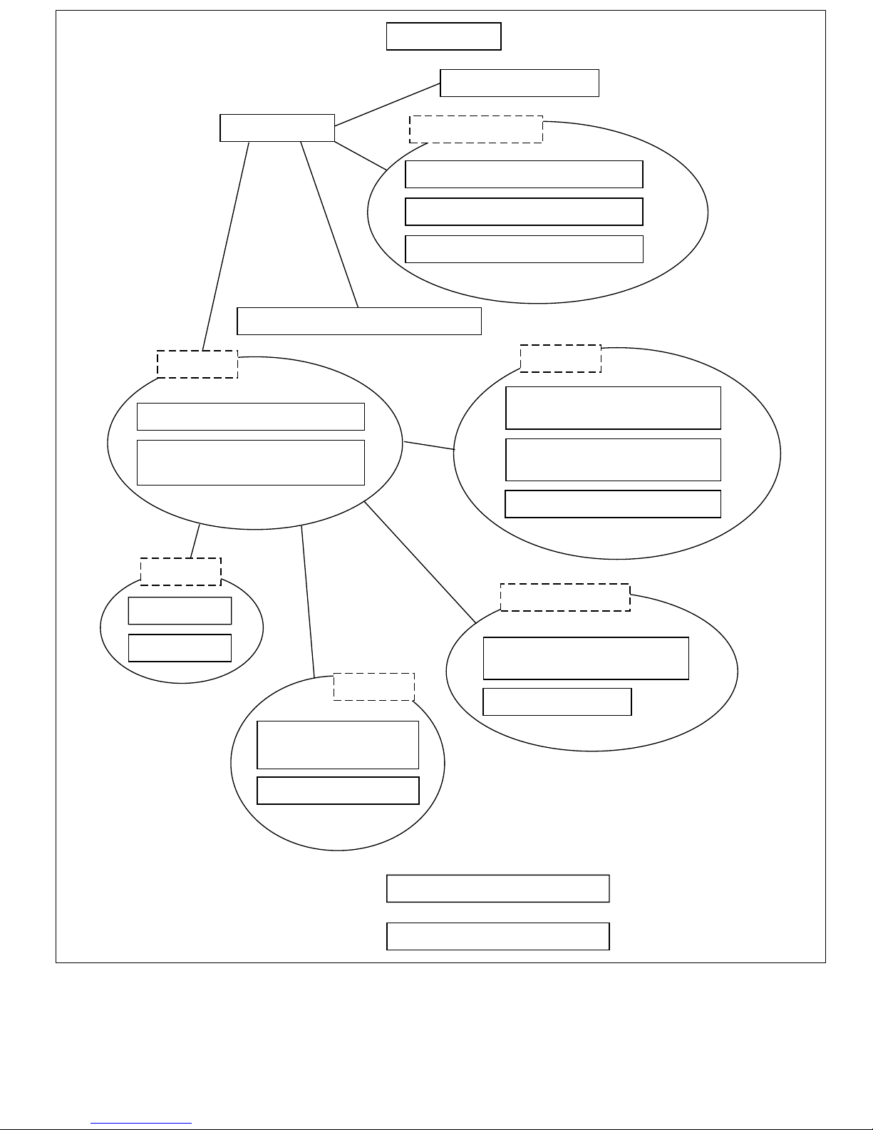
Organization of This Manual
Table 1 describes how this manual is organized. Figure 1 shows the relationships between the
sections within this manual.
Table 1 Manual Organization
Abbrevi-
Category Section Title
Overview 1. Overview — Features, internal block diagram, pin
CPU 2. CPU CPU Register configuration, data structure.
ation Contents
layout, pin functions
instruction features, instruction types,
instruction lists
Operating
Modes
Internal
Modules
Clock 7. Clock Pulse
Buses 8. Bus State
Timers 10. 16-Bit Integrated
3. Operating Modes — MCU mode, PROM mode
4. Exception
Handling
5. Interrupt
Controller
6. User Break
Controller
Generator
Controller
9. Direct Memory
Access
Controller
Timer Pulse Unit
— Resets, address errors, interrupts, trap
instructions, illegal instructions
INTC NMI interrupts, user break interrupts, IRQ
interrupts, on-chip module interrupts
UBC Break address and break bus cycle
selection
CPG Crystal pulse generator, duty correction
circuit
BSC Division of memory space, DRAM
interface, refresh, wait state control, parity
control
DMAC Auto request, external request, on-chip
peripheral module request, cycle steal
mode, burst mode
ITU Waveform output mode, input capture
function, counter clear function, buffer
operation, PWM mode, complementary
PWM mode, reset synchronized mode,
synchronized operation, phase counting
mode, compare match output mode
11. Programmable
Timing Pattern
Controller
12. Watchdog Timer WDT Watchdog timer mode, interval timer mode
Data
Processing
13. Serial
Communication
Interface
14. A/D Converter A/D Single mode, scan mode, activation by
TPC Compare match output triggers, non-
overlap operation
SCI Asynchronous mode, synchronous mode,
multiprocessor communication function
external trigger
Page 7

Table 1 Manual Organization (cont)
Category Section Title
Abbreviation Contents
Pins 15. Pin Function
PFC Pin function selection
Controller
16. Parallel I/O
I/O I/O ports
Ports
Memory 17. ROM ROM PROM mode, high-speed programming
system
18. RAM RAM On-chip RAM
Power-Down
State
Electrical
Char act er i s t i c s
19. Power-Down
State
20. Electrical
Characteristics
— Sleep mode, standby mode
— Absolute maximum ratings, AC
characteristics, DC characteristics,
operation timing
Page 8
1. Overview
3. Operating modes
2. CPU
7. Clock pulse generator (CPG)
Buses
8. Bus state controller (BSC)
9. Direct memory access
controller (DMAC)
On-chip modules
4. Exception handling
5. Interrupt controller (INTC)
6. User break controller (UBC)
Timers
10. 16-bit integrated timer
pulse unit (ITU)
11. Programmable timing
pattern controller (TPC)
12. Watchdog timer (WDT)
Memory
17. ROM
18. RAM
Data processing
13. Serial communication
interface (SCI)
Pins
14. A/D converter
15. Pin function
controller (PFC)
16. Parallel I/O ports
19. Power-down state
20. Electrical characteristics
Figure 1 Manual Organization
Page 9

Addresses of On-Chip Peripheral Module Registers
The on-chip peripheral module registers are located in the on-chip peripheral module space (area
5: H'5000000–H'5FFFFFF), but since the actual register space is only 512 bytes, address bits
A23–A9 are ignored. 32k shadow areas in 512 byte units that contain exactly the same contents as
the actual registers are thus provided in the on-chip peripheral module space.
In this manual, register addresses are specified as though the on-chip peripheral module registers
were in the 512 bytes H'5FFFE00–H'5FFFFFF. Only the values of the A27–A24 and A8–A0 bits
are valid; the A23–A9 bits are ignored. When area H'5000000–H'50001FF is accessed, for
example, the result will be the same as when area H'5FFFE00–H'5FFFFFF is accessed. For more
details, see Section 8.3.5, Area Descriptions: Area 5.
Page 10
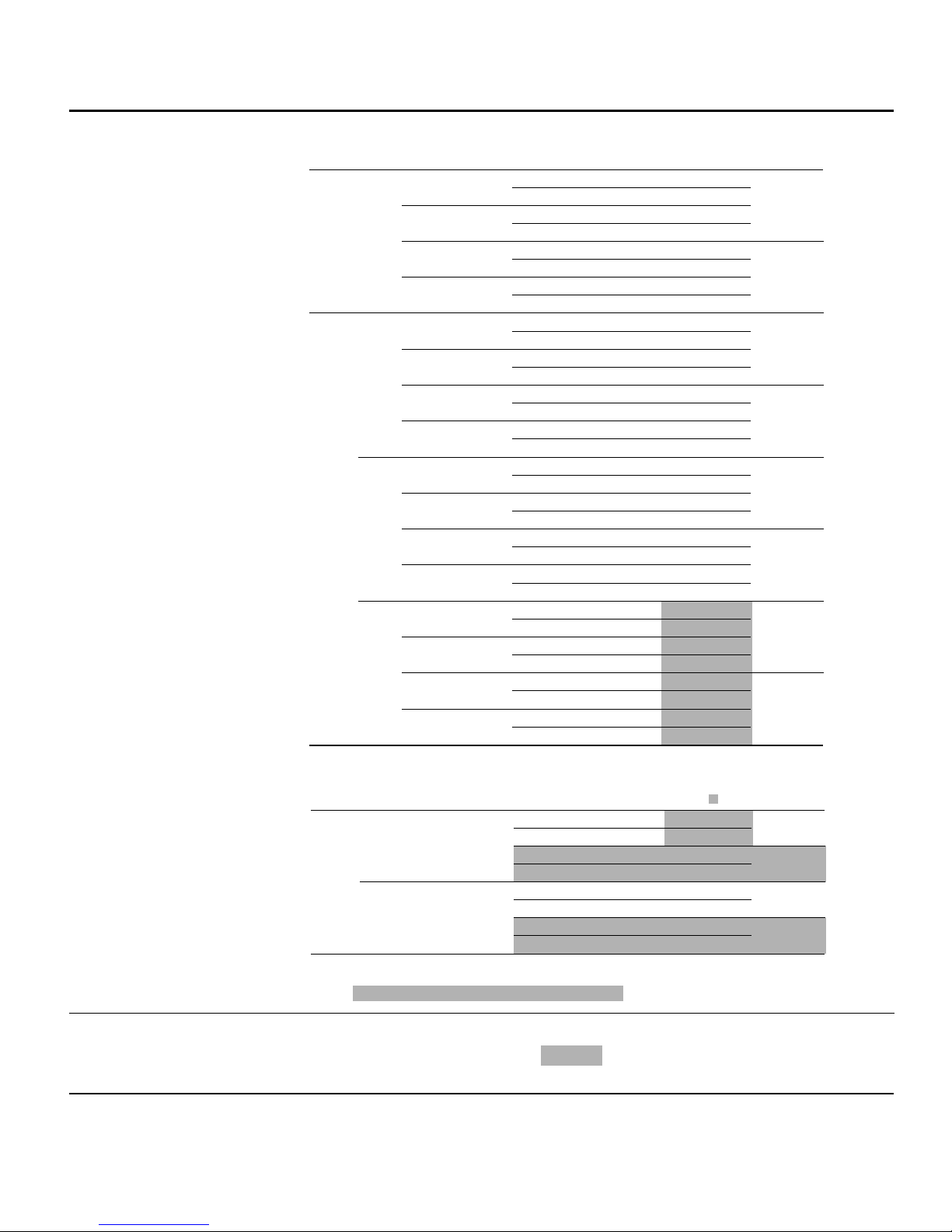
List of Items Revised or Added for This Version
Section Page Description Edition
1.1 SuperH
Microcomputer
Features
Table 1.2 Product
Lineup
6, 7 SH7034, SH7032: 2 to 16.6 MHz device deleted.
Product
Number
SH7032 ROMless 5.0 V 2 to 20 MHz -20 to +75°C HD6417032F20 HD6417032F20 112-pin plastic
SH7034 PROM 5.0 V 2 to 20 MHz -20 to +75°C HD6477034F20 HD6477034F20 112-pin plastic
On-Chip
Operating
ROM
Mask 5.0 V 2 to 20 MHz -20 to +75°C HD6437034AF20 HD6437034AF20 112-pin plastic
ROM
ROMless 5.0 V 2 to 20 MHz -20 to +75°C HD6417034F20 HD6417034F20 112-pin plastic
Operating
Voltage
Frequency
3.3 V 2 to 12.5 MHz -20 to +75°C HD6417032VF12 HD6417032VF12
5.0 V 2 to 20 MHz -20 to +75°C HD6417032X20 HD6417032TE20 120-pin plastic
3.3 V 2 to 12.5 MHz -20 to +75°C HD6417032VX12 HD6417032VTE12
3.3 V 2 to12.5 MHz -20 to +75°C HD6 4 7 70 3 4 V F1 2 HD6 4 7 70 3 4 V F1 2
5.0 V 2 to 20 MHz -20 to +75°C HD6477034X20 HD6 4 7 70 3 4 TE 2 0 120-pin plastic
3.3 V 2 to 12.5 MHz -20 to +75°C HD6 4 7 70 3 4 V X 1 2 HD6 4 7 70 3 4 V TE 1 2
3.3 V 2 to 12.5 MHz -20 to +75°C HD6437034AVF12 HD6437034AF12
5.0 V 2 to 20 MHz -20 to +75°C HD6437034AX20 HD6437034ATE20 120-pin plastic
3.3 V 2 to 12.5 MHz -20 to +75°C HD6437 0 3 4 A VX 1 2 HD6437034ATE12
3.3 V 2 to 12.5 MHz -20 to +75°C HD6417034VF12 HD6417034VF12
5.0 V 2 to 20 MHz -20 to +75°C HD6417034X20 HD6417034TE20 120-pin plastic
3.3 V 2 to 12.5 MHz -20 to +75°C HD6417034VX12 HD6417034VTE12
Temperature
Range Model
-40 to +85°C HD6417032FI20 HD6417032FI20
-40 to +85°C HD6417032VFI12 HD6417032VFI12
-40 to +85°C HD6417032XI20 HD6417032TEI20
-40 to +85°C HD6417032VXI12 HD6417032VTEI12
-40 to +85°C HD6477034FI20 HD6477034FI20
-40 to +85°C HD6 4 7 70 3 4 V FI 1 2 HD6 4 7 70 3 4 V FI 1 2
-40 to +85°C HD6477034XI20 HD6 4 7 70 3 4 TE I 2 0
-40 to +85°C HD6 4 7 70 3 4 V X I 1 2 HD6 4 7 70 3 4 V TE I 1 2
-40 to +85°C HD6437034AFI20 HD6437034AFI20
-40 to +85°C HD6437034AVFI12 HD6437034AFI12
-40 to +85°C HD6437034AXI20 HD6437034ATEI20
-40 to +85°C HD6437034AVXI12 HD6437034ATEI12
-40 to +85°C HD6417034FI20 HD6417034FI20
-40 to +85°C HD6417034VFI12 HD6417034VFI12
-40 to +85°C HD6417034XI20 HD6417034TEI20
-40 to +85°C HD6417034VXI12 HD6417034VTEI12
Marking
Model No.
6
2
*
Package
QFP (FP-112)
TQFP (TFP-120)
QFP (FP-112)
TQFP (TFP-120)
QFP (FP-112)
TQFP (TFP-120)
QFP (FP-112)
TQFP (TFP-120)
Product
Number
SH7034B
Notes: *1 The electrical characteristics of the SH7034B mask ROM version and SH7034 PROM
1.3.2 Pin Functions
Table 1.3 Pin
12 Note amended
*2 Can be used in the SH7034 PROM version.
Functions
On-Chip
Operating
Voltage
Operating
Frequency
ROM
1
*
Mask 3.3 V 4 to 12.5 MHz -20 to +75°C HD6437034BVF12 6437034B(***)F 112-pin plastic
ROM
ROMless 3.3 V 4 to 20 MHz -20 to +75°C HD6417034BVF20 HD6417034BVF20 112-pin plastic
Temperature
Range Model
-40 to +85°C HD6437034BVFW12 6437034B(***)FW
-20 to +75°C HD6437034BVX12 6437034B(***)X 120-pin plastic
-40 to +85°C HD6437034BVXW12 6437034B(***)XW
-40 to +85°C HD6417034BVFW20 HD6417034BVFW20
-20 to +75°C HD6417034BVX20 6417034BVTE20 120-pin plastic
-40 to +85°C HD6417034BVXW20 6417034BVTEW20
Marking
Model No.
2
*
Package
QFP (FP-112)
TQFP (TFP-120)
QFP (FP-112)
TQFP (TFP-120)
version are different.
*2 For mask ROM versions, (***) is the ROM code.
6
Page 11
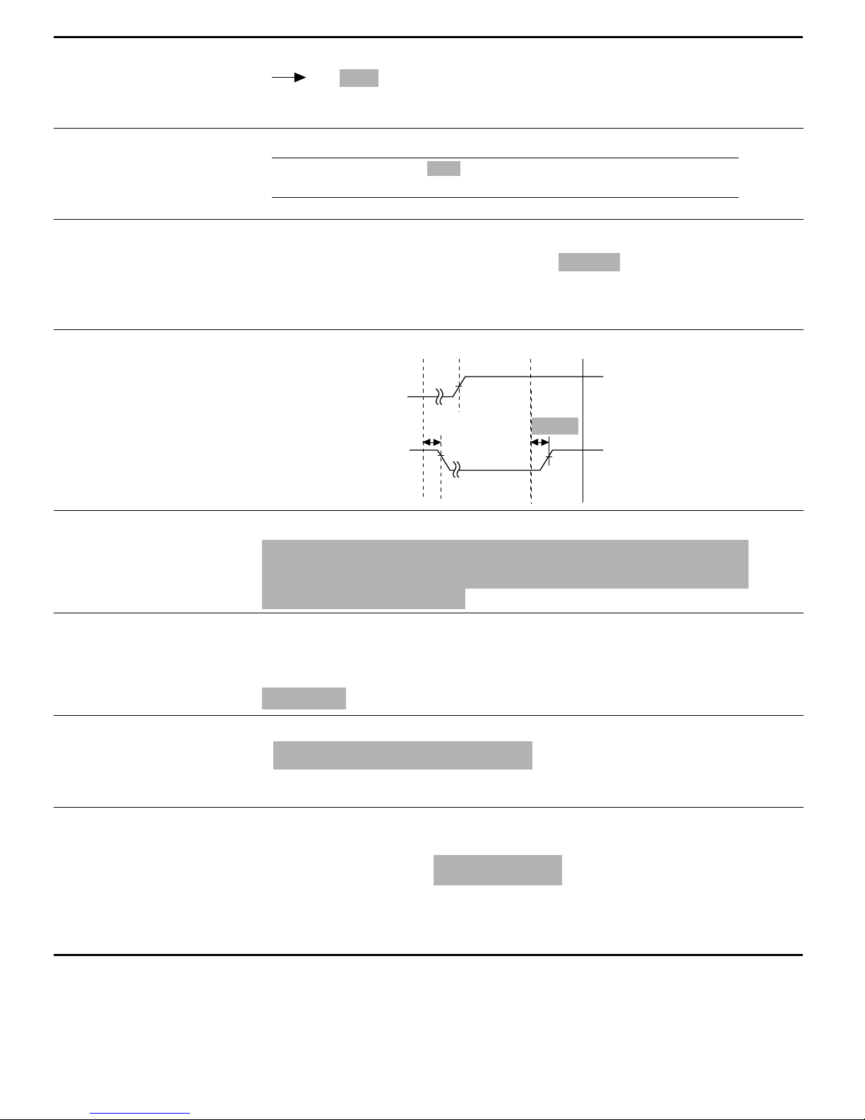
Section Page Description Edition
2.1.2 Control
Registers
Figure 2.2 Control
Registers
2.1.4 Initial Values
of Registers
Table 2.1 Initial
Values of Registers
3.1 Types of
Operating Modes and
Their Selection
Table 3.1 Operating
Mode Selection
8.11.3 Maximum
Number of States
from BREQ Input to
Bus Release
Figure 8.47 Bus
Release Procedure
18 Description amended
Bits I3–I0: Interrupt mask bits.
19 Description amended
SR Bits I3–I0 are 1111(H'F), reserved bits are 0, and other
49 Note amended
*2 Only modes 0 and 1 are available in the SH7032 and SH7034
ROMless version.
174 Description amended
bits are undefined
t
BRQS
t
BACD1
t
BACD2
6
6
6
6
9.1.4 Register
Configuration
Table 9.2 DMAC
Registers
9.3.4 DMA Transfer
Types
10.1.4 Register
Configuration
Table 10.3 Register
Configuration
10.4.5 ResetSynchronized PWM
Mode
Procedure for
Selecting ResetSynchronized PWM
Mode (figure 10.31):
179 *4 added
*4 Only the values of bits A27–A24 and A8–A0 are valid; bits A23–A9
are ignored. For details on the register addresses, see section
8.3.5, Area Descriptions.
200 Description amended
Line 3
⋅⋅⋅ destination or source must be the SCI or A/D converter
(table 9.4). ⋅⋅⋅
230 *2 description amended
*2 Only 0 can be written to clear flags.
268 Description amended
4. Set bits CMD1 and CMD0 in TFCR to select reset-synchronized
PWM mode. TIOCA3, TIOCB3, TIOCA4, TIOCB4, TOCXA4, and
TOCXB4 become PWM output pins.
6
6
6
6
Page 12

Section Page Description Edition
10.4.6
Complementary
PWM Mode
Procedure for
Selecting
Complementary
PWM Mode (Figure
10.33):
10.6.15 ITU
Operating Modes
Table 10.18 ITU
Operating Modes
(Channel 0)
Table 10.19 ITU
Operating Modes
(Channel 1)
271 Description amended
3. Set bits CMD1 and CMD0 in TMDB to select complementary PWM
mode. TIOCA3, TIOCB3, TIOCA4, TIOCB4, TOCXA4, and
TOCXB4 become PWM pins.
301 Table amended
TSNC TMDR TFCR TOCR TIOR0 TCR0
Operating
Mode Sync MDF FDIR PWM
Synch-
ronized
preset
PWM √ — — PWM0
Output
compare A
function
SYNC0
——√ ——— — √√ √√
= 1
√ — — PWM0
302 Table amended
TSNC TMDR TFCR TOCR TIOR1 TCR1
Operating
Mode Sync MDF FDIR PWM
Synch-
ronized
preset
PWM √ — — PWM1
Output
compare A
function
SYNC1
——√ ——— — √√ √√
= 1
√ — — PWM1
Register Setting
Reset
Comp
Sync
PWM
PWM Buffer
——— — — √ * √√
= 1
— — — — IOA2 = 0,
= 0
Register Setting
Reset
Comp
Sync
PWM
PWM Buffer
——— — — √
= 1
— — — — IOA2 = 0,
= 0
Output
Level
Select IOA IOB
√√√
others:
don’t care
Output
Level
Select IOA IOB
√√√
others:
don’t care
*
Clear
Clock
Select
Select
Clear
Clock
Select
Select
√√
6
6
6
Table 10.20 ITU
Operating Modes
(Channel 2)
12.1.4 Register
Configuration
Table 12.2 WDT
Registers
303 Table amended
TSNC TMDR TFCR TOCR TIOR2 TCR2
Operating
Mode Sync MDF FDIR PWM
Synch-
ronized
preset
PWM √ — — PWM2
Output
compare A
function
SYNC2
——√ ——— — √√ √√
= 1
√ — — PWM2
337 *4 added
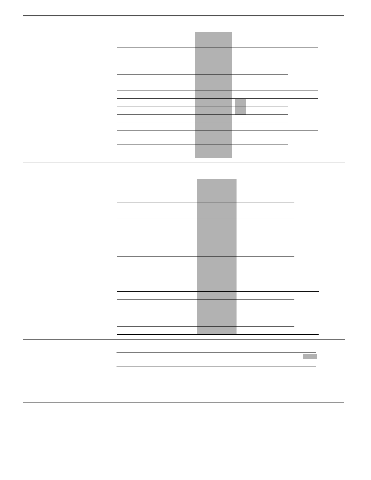
Name Abbreviation R/W Value Write
Timer control/status register TCSR R/(W)
Timer counter TCNT R/W H'00 H'5FFFFB9
Reset control/status register RSTCSR R/(W)
Notes: *1 Write by word transfer. A byte or longword write cannot be used.
*2 Read by byte transfer. The correct value cannot be obtained by a word or longword
read.
*3 Only 0 can be written in bit 7, to clear the flag.
*4 Only the values of bits A27–A24 and A8–A0 are valid; bits A23–A9 are ignored. For
details on the register addresses, see section 8.3.5, Area Descriptions
Register Setting
Reset
Comp
Sync
PWM
PWM Buffer
——— — — √
= 1
— — — — IOA2 = 0,
= 0
Output
Level
Select IOA IOB
3
*
3
*
Clear
Clock
Select
Select
*
√√
√√√
others:
don’t care
4
*
Initial
1
*
Address
Read
2
*
H'18 H'5FFFFB8 H'5FFFFB8
H'1F H'5FFFFBA H'5FFFFBB
6
6
Page 13

Section Page Description Edition
12.2.2 Timer
Control/Status
Register (TCSR)
13.2.6 Serial Control
Register
13.2.8 Bit Rate
Register (BRR)
Table 13.3 Bit Rates
and BRR Settings in
Asynchronous Mode
Table 13.4 Bit
Rates and BRR
Settings in
Synchronous Mode
338 Note added
Note: * Only 0 can be written, to clear the flag.
359 Initial value added
Internal clock, SCK pin used for input pin (input signal
2
is ignored) or output pin (output level is undefined)
*
(Initial value)
2
Internal clock, SCK pin used for serial clock output
*
(Initial value)
367 Note added
Note: Settings with an error of 1% or less are recommended.
368 Note deleted 6
6
6
6
15.2 Register
Configuration
Table 15.2 Pin
Function Controller
Registers
16.2.1 Register
Configuration
Table 16.1 Port A
Register
16.3.1 Register
Configuration
Table 16.3 Port B
Register
427 Note added
Name Abbreviation R/W Initial Value Address* Access Size
Port A I/O register PAIOR R/W H'0000 H'5FFFFC4 8, 16, 32
Port A control register 1 PACR1 R/W H'3302 H'5FFFFC8 8, 16, 32
Port A control register 2 PACR2 R/W H'FF95 H'5FFFFCA 8, 16, 32
Port B I/O register PBIOR R/W H'0000 H'5FFFFC6 8, 16, 32
Port B control register 1 PBCR1 R/W H'0000 H'5FFFFCC 8, 16, 32
Port B control register 2 PBCR2 R/W H'0000 H'5FFFFCE 8, 16, 32
Column address strobe
pin control register
Note: * Only the values of bits A27–A24 and A8–A0 are valid; bits A23–A9 are ignored. For
details on the register addresses, see section 8.3.5, Area Descriptions.
442 Note added
Name Abbreviation R/W Initial Value Address* Access Size
Port A data register PADR R/W H'0000 H'5FFFFC0 8, 16, 32
Note: * Only the values of bits A27–A24 and A8–A0 are valid; bits A23–A9 are ignored. For
details on the register addresses, see section 8.3.5, Area Descriptions.
443 Note added
Name Abbreviation R/W Initial Value Address* Access Size
Port B data register PBDR R/W H'0000 H'5FFFFC2 8, 16, 32
Note: * Only the values of bits A27–A24 and A8–A0 are valid; bits A23–A9 are ignored. For
details on the register addresses, see section 8.3.5, Area Descriptions.
6
CASCR R/W H'5FFF H'5FFFFEE 8, 16, 32
6
6
16.4.1 Register
Configuration
Table 16.5 Port C
Register
445 Note added
Name Abbreviation R/W Initial Value Address* Access Size
Port C data register PCDR R/W H'5FFFFD0 8, 16, 32
Note: * Only the values of bits A27–A24 and A8–A0 are valid; bits A23–A9 are ignored. For
6
—
details on the register addresses, see section 8.3.5, Area Descriptions.
Page 14

Section Page Description Edition
19.1.2 Register
Table 19.2 Standby
Control Register
(SBYCR)
20.1.2 DC
Characteristics
Table 20.2 DC
Characteristics
Table 20. 2 DC
Characteristics
Table 20.3
Permitted Output
Current Values
20.1.3 AC
Characteristics
(1) Clock Timing
Table 20.4 Clock
Timing
460 Note added
Name Abbreviation R/W Initial Value Address* Access size
Standby control register SBYCR R/W H'1F H'5FFFFBC 8, 16, 32
Note: * Only the values of bits A27–A24 and A8–A0 are valid; bits A23–A9 are ignored. For
details on the register addresses, see section 8.3.5, Area Descriptions.
467 16.6 MHz deleted 6
Table of 16.6 MHz deleted 6
471 16.6 MHz deleted 6
472 16.6 MHz deleted 6
6
(2) Control Signal
Timing
Table 20.5 Control
Signal Timing
(3) Bus Timing
Table 20.6 Bus
Timing (1)
Table 20.7 Bus
Timing (2)
474 16.6 MHz deleted 6
478,
479
Description amended
6
Read data access time 1
Read data access time 2
Read data access time from
6
*
CAS 2
Read data access time from
6
*
RAS 1
Read data access time from
6
*
RAS 2
Data setup time for CAS t
CAS setup time for RAS t
Row address hold time t
*
6
*
Table deleted
t
ACC1
t
ACC2
t
CAC2
t
RAC1
t
RAC2
DS
CSR
RAH
4
*
t
– 30
cyc
t
× (n+2) –
cyc
3
*
30
t
× (n+1) –
cyc
3
*
25
t
× 1.5 – 20 — ns 20.11, 20.12
cyc
t
× (n+2.5)
cyc
3
*
– 20
5
*
0
10 — ns 20.16–20.18
10 — ns 20.11, 20.13
— ns 20.8, 20.11, 20.12
— ns 20.9, 20.10,
—ns
—ns
— ns 20.11, 20.13
20.13–20.15
20.13–20.15
20.13–20.15
6
6
Table 20.7 Bus
Timing (2)
494 Description amended
Read data access time 1
Read data access time 2
4
*
4
*
t
ACC1tcyc
t
ACC2tcyc
– 44 — ns 20.21, 20.24, 20.25
2
× (n+2) – 44
*
— ns 20.22, 20.23,
20.26–20.28
6
Page 15

Section Page Description Edition
(4) DMAC Timing
Table 20.8 DMAC
Timing
(5) 16-bit Integrated
Timer Pulse Unit
Timing
Table 20.9 16-bit
Integrated Timer
Pulse Unit Timing
(6) Programmable
Timing Pattern
Controller and I/O
Port Timing
Table 20.10
Programmable
Timing Pattern
Controller and I/O
Port Timing
507 16.6 MHz deleted 6
509 16.6 MHz deleted 6
510 16.6 MHz deleted 6
(7) Watchdog Timer
Timing
Table 20.11
Watchdog Timer
Timing
(8) Serial
Communication
Interface Timing
Table 20.12 Serial
Communication
Interface Timing
(9) A/D Converter
Timing
Table 20.13 A/D
Converter Timing
20.1.4 A/D
Converter
Characteristics
511 16.6 MHz deleted
512 16.6 MHz deleted
513 16.6 MHz deleted
516 16.6 MHz deleted
6
6
6
6
Table 20.14 A/D
Converter
Characteristics
20.2 SH7034B 3.3 V
517 12.5 MHz added 6
12.5 MHz Version
and 20 MHz
1
Version
*
Electrical
Characteristics
Page 16

Section Page Description Edition
20.2.1 Absolute
Maximum Ratings
Table 20.15
Absolute Maximum
Ratings
Table 20.16 DC
Characteristics
517 Notes amended
Item Symbol Rating Unit
Power supply voltage V
Input voltage (except port C) V
Input voltage (port C) V
Analog power supply voltage AV
Analog reference voltage AV
Analog input voltage V
Operating temperature T
Storage temperature T
518,
Caution: Operating the chip in excess of the absolute maximum rating may result in permanent
Notes: *1 ROMless products only for 20 MHz version
12.5 MHz added
damage.
*2 Regular-specification products; for wide-temperature-range products, Topr = –40 to
+85°C
519
Conditions: VCC = 3.3 V ±0.3V, AVCC = 3.3 V ±0.3V, AVCC = VCC ±0.3V, AV
AV
CC
Notes: *1 ROMless products only for 20 MHz version
*2 Regular-specification products; for wide-temperature-range products, Ta = –40 to
+85°C
CC
in
in
CC
ref
AN
opr
stg
, VSS = AVSS = 0 V, φ = 12.5 to 20 MHz
–0.3 to +4.6 V
–0.3 to VCC + 0.3 V
–0.3 to AVCC + 0.3 V
–0.3 to +4.6 V
–0.3 to AVCC + 0.3 V
–0.3 to AVCC + 0.3 V
–20 to +75
–55 to +125 ˚C
1
*
, Ta = –20 to +75°C
2
*
= 3.0 V to
ref
2
*
6
˚C
6
Table 20.17
Permitted Output
Current Values
Current Ordinary I
consumption operation
Sleep — 20 — mA f = 12.5 MHz
Standby — 0.1 5 µA Ta ≤ 50°C
521 12.5 MHz added
Item Symbol Min Typ Max Min Typ Max Unit
Output low-level
permissible current
(per pin)
Output low-level
permissible current
(total)
Output high-level
permissible current
(per pin)
Output high-level
permissible current
(total)
Caution: To ensure reliability of the chip, do not exceed the output current values given in table
20.18.
I
OL
∑ I
–I
–∑ I
OH
CC
— 25 — mA f = 12.5 MHz
— 35 60 mA f = 20 MHz
— 30 40 mA f = 20 MHz
——10 µA50°C < Ta
6
12.5 MHz 20 MHz
——10 ——10mA
OL
——80 ——80mA
——2.0 ——2.0mA
——25 ——25mA
OH
Page 17
Section Page Description Edition
20.2.3 AC
Characteristics
(1) Clock Timing
Table 20.18 Clock
Timing
(2) Control Signal
Timing
Table 20.19 Control
Signal Timing
522 12.5 MHz added and description amended
12.5 MHz 20 MHz
Item Symbol Min Max Min Max Unit Figures
EXTAL input high level
pulse width
EXTAL input low level
pulse width
EXTAL input rise time t
EXTAL input fall time t
Clock cycle time t
Clock high pulse width t
Clock low pulse width t
Clock rise time t
Clock fall time t
Reset oscillation settling
time
Software standby
oscillation settling time
t
EXH
t
EXL
EXr
EXf
cyc
CH
CL
Cr
Cf
t
OSC1
t
OSC2
22 — 15 — ns 20.45
22 — 15 — ns
—10 —5 ns
—10 —5 ns
80 500 50 250 ns 20.45, 20.46
30 — 20 — ns 20.46
30 — 20 — ns
—10 —5 ns
—10 —5 ns
10 — 10 — ms 20.47
10 — 10 — ms
524 12.5 MHz added and description amended
12.5 MHz 20 MHz
Item Symbol Min Max Min Max Unit Figure
RES setup time t
RES pulse width t
NMI reset setup time t
NMI reset hold time t
NMI setup time t
NMI hold time t
IRQ0–IRQ7 setup time
(edge detection)
IRQ0–IRQ7 setup time
(level detection)
IRQ0–IRQ7 hold time t
IRQOUT output delay
time
Bus request setup time t
Bus acknowledge delay
time 1
Bus acknowledge delay
time 2
Bus 3-state delay time t
RESS
RESW
NMIRS
NMIRH
NMIS
NMIH
t
IRQES
t
IRQLS
IRQEH
t
IRQOD
BRQS
t
BACD1
t
BACD2
BZD
320 — 200 — ns 20.48
20 — 20 — t
320 — 200 — ns
320 — 200 — ns
160 — 100 — ns 20.49
80 — 50 — ns
160 — 100 — ns
160 — 100 — ns
80 — 50 — ns
— 80 — 50 ns 20.50
80 — 50 — ns 20.51
— 80 — 50 ns
— 80 — 50 ns
— 80 — 50 ns
6
6
cyc
(3) Bus Timing
Table 20.20 Bus
528 Description amended
Read data access time 2
Timing (1)
(3) Bus Timing
Table 20.20 Bus
530 to
532
Newly added 6
Timing (2)
6
6
*
t
ACC2
t
× (n+2) –
cyc
3
*
30
— ns 20.53, 20.54, 20.57–20.59
Page 18
Section Page Description Edition
(4) DMAC Timing
Table 20.21 DMAC
Timing
(5) 16-bit Integrated
Timer Pulse Unit
Timing
Table 20.22 16-bit
Integrated Timer
Pulse Unit Timing
(6) Programmable
Timing Pattern
Controller and I/O
Port Timing
Table 20.23
Programmable
Timing Pattern
Controller and I/O
Port Timing
546 12.5 MHz added
Item Symbol Min Max Min Max Unit Figure
DREQ0, DREQ1 setup time t
DREQ0, DREQ1 hold time t
DREQ0, DREQ1 Pulse width t
547 12.5 MHz added
Item Symbol Min Max Min Max Unit Figure
Output compare delay time t
Input capture setup time t
Timer clock input setup time t
Timer clock pulse width
(single edge)
Timer clock pulse width
(both edges)
548 Description amended
Conditions: VCC = 3.3 V ±0.3V, AVCC = 3.3 V ±0.3V, AVCC = VCC ±0.3V, AV
, VSS = AVSS = 0 V, φ = 12.5 to 20 MHz
AV
CC
Notes: *1 ROMless products only for 20 MHz version
*2 Regular-specification products; for wide-temperature-range products, Ta = –40 to
+85°C
DRQS
DRQH
DRQW
TOCD
TICS
TCKS
t
TCKWH/L
t
TCKWL/L
12.5 MHz 20 MHz
80 — 27 — ns 20.65
30 — 30 — ns
1.5 — 1.5 — t
12.5 MHz 20 MHz
— 100 — 100 ns 20.67
50 — 35 — ns
50 — 50 — ns 20.68
1.5 — 1.5 — t
2.5 — 2.5 — t
1
*
, Ta = –20 to +75°C
cyc
cyc
cyc
= 3.0 V to
ref
2
*
20.66
6
6
6
(7) Watchdog Timer
Timing
Table 20.24
Watchdog Timer
Timing
(8) Serial
Communication
Interface Timing
Table 20.25 Serial
Communication
Interface Timing
(9) A/D Converter
Timing
Table 20.26 A/D
Converter Timing
549 Description amended
Conditions: VCC = 3.3 V ±0.3V, AVCC = 3.3 V ±0.3V, AVCC = VCC ±0.3V, AV
AV
, VSS = AVSS = 0 V, φ = 12.5 to 20 MHz
CC
Notes: *1 ROMless products only for 20 MHz version
*2 Regular-specification products; for wide-temperature-range products, Ta = –40 to
+85°C
550 Description amended
Conditions: VCC = 3.3 V ±0.3V, AVCC = 3.3 V ±0.3V, AVCC = VCC ±0.3V, AV
, VSS = AVSS = 0 V, φ = 12.5 to 20 MHz
AV
CC
Notes: *1 ROMless products only for 20 MHz version
*2 Regular-specification products; for wide-temperature-range products, Ta = –40 to
+85°C
551 Description amended
Conditions: VCC = 3.3 V ±0.3V, AVCC = 3.3 V ±0.3V, AVCC = VCC ±0.3V, AV
, VSS = AVSS = 0 V, φ = 12.5 to 20 MHz
AV
CC
Notes: *1 ROMless products only for 20 MHz version
*2 Regular-specification products; for wide-temperature-range products, Ta = –40 to
+85°C
1
*
, Ta = –20 to +75°C
1
*
, Ta = –20 to +75°C
1
*
, Ta = –20 to +75°C
= 3.0 V to
ref
2
*
= 3.0 V to
ref
2
*
= 3.0 V to
ref
2
*
6
6
6
Page 19

Section Page Description Edition
20.2.4 A/D
Converter
Characteristics
Table 20.27 A/D
Converter
Characteristics
A.2.17 Timer Status
Registers 0–4
(TSR0–TSR4)
Table A.18 TSR0–
TSR4 Bit Functions
554 12.5 MHz added
Item Min Typ Max Min Typ Max Unit
Resolution 101010 101010bit
Conversion time — — 11.2 — — 6.7 µS
Analog input capacitance — — 20 — — 20 pF
Permissible signal-source impedance — — 1 — — 1 kΩ
Nonlinearity error* ——±4.0 — — ±4.0 LSB
Offset error* ——±4.0 — — ±4.0 LSB
Full-scale error* ——±4.0 — — ±4.0 LSB
Quantization error* ——±0.5 — — ±0.5 LSB
Absolute accuracy — — ±6.0 — — ±6.0 LSB
Note: *Reference value
581 Bit amended
Bit Bit name Value Description
2 Overflow flag (OVF) 0 Clear conditions: 0 is written in OVF after
1 Input capture/compare match
flag B (IMFB)
0 Input capture/compare match
flag A (IMFA)
6
12.5 MHz 20 MHz
6
reading OVF = 1 (Initial value)
1 Set conditions: TCNT value overflows (H'FFFF
? H'0000) or underflows (H'FFFF ? H'0000)
0 Clear conditions: 0 is written in IMFB after
reading IMFB = 1 (Initial value)
1 Set conditions: (1) When GRB is functioning as
the output compare register, and TCNT = GRB;
(2) When GRB is functioning as the input
capture register, and the TCNT value is
transferred to GRB by the input capture signal
0 Clear conditions: 0 is written in IMFA after
reading IMFA = 1 (Initial value)
1 Set conditions: (1) When GRA is functioning as
the output compare register, and TCNT = GRA;
(2) When GRA is functioning as the input
capture register, and the TCNT value is
transferred to GRA by the input capture signal
A.2.23 Timer Output
Control Register
(TOCR)
Table A.24 TOCR
Bit Functions
587 Table amended
Bit Bit name Value Description
1 Output level select 4 (OLS4) 0 Reverse output of TIOCA3, TIOCA4, TIOCB4
0 Output level select 3 (OLS3) 0 Reverse output of TIOCB3, TOCXA4, TOCXB4
6
1 Direct output of TIOCA3, TIOCA4, TIOCB4
(Initial value)
1 Direct output of TIOCB3, TOCXA4, TOCXB4
(Initial value)
Page 20

Section Page Description Edition
A.3 Register Status
in Reset and PowerDown States
Table A.77 Register
Status in Reset and
Power-Down States
644 *2 added
Watchdog timer (WDT) TCNT Initialized Initialized Held Held
Serial communication SMR Initialized Initialized Initialized Held
interface (SCI)
Notes: *1 Bits 7–5 (OVF, WT/IT, TME) are initialized, bits 2–0 (CKS2–CKS0) are held.
*2 Not initialized in the case of a reset by the WDT.
1
TCSR
2
*
RSTCR
BRR
SCR
TDR
TSR Held
SSR Initialized
RDR
RSR Held
*
Initialized
6
Page 21

Page 22

Contents
Section 1 Overview............................................................................................................ 1
1.1 SuperH Microcomputer Features ....................................................................................... 1
1.2 Block Diagram.................................................................................................................... 8
1.3 Pin Descriptions.................................................................................................................. 9
1.3.1 Pin Arrangement ................................................................................................... 9
1.3.2 Pin Functions......................................................................................................... 11
1.3.3 Pin Layout by Mode.............................................................................................. 15
Section 2 CPU...................................................................................................................... 17
2.1 Register Configuration ....................................................................................................... 17
2.1.1 General Registers (Rn).......................................................................................... 17
2.1.2 Control Registers................................................................................................... 18
2.1.3 System Registers................................................................................................... 19
2.1.4 Initial Values of Registers..................................................................................... 19
2.2 Data Formats ...................................................................................................................... 20
2.2.1 Data Format in Registers....................................................................................... 20
2.2.2 Data Format in Memory........................................................................................ 20
2.2.3 Immediate Data Format ........................................................................................ 21
2.3 Instruction Features............................................................................................................ 21
2.3.1 RISC-Type Instruction Set.................................................................................... 21
2.3.2 Addressing Modes................................................................................................. 24
2.3.3 Instruction Formats ............................................................................................... 27
2.4 Instruction Set .................................................................................................................... 31
2.4.1 Instruction Set by Classification ........................................................................... 31
2.4.2 Operation Code Map............................................................................................. 42
2.5 CPU State ........................................................................................................................... 45
2.5.1 State Transitions.................................................................................................... 45
2.5.2 Power-Down State ................................................................................................ 48
Section 3 Operating Modes ............................................................................................. 49
3.1 Types of Operating Modes and Their Selection................................................................. 49
3.2 Operating Mode Descriptions ............................................................................................ 49
3.2.1 Mode 0 (MCU Mode 0) ........................................................................................ 49
3.2.2 Mode 1 (MCU Mode 1) ........................................................................................ 49
3.2.3 Mode 2 (MCU Mode 2) ........................................................................................ 49
3.2.4 Mode 7 (PROM Mode)......................................................................................... 49
Section 4 Exception Handling........................................................................................ 51
4.1 Overview............................................................................................................................ 51
i
Page 23

4.1.1 Exception Handling Types and Priorities.............................................................. 51
4.1.2 Exception Handling Operation.............................................................................. 53
4.1.3 Exception Vector Table ........................................................................................ 54
4.2 Resets.................................................................................................................................. 56
4.2.1 Reset Types ........................................................................................................... 56
4.2.2 Power-On Reset .................................................................................................... 57
4.2.3 Manual Reset......................................................................................................... 57
4.3 Address Errors.................................................................................................................... 58
4.3.1 Address Error Sources .......................................................................................... 58
4.3.2 Address Error Exception Handling ....................................................................... 58
4.4 Interrupts ............................................................................................................................ 59
4.4.1 Interrupt Sources ................................................................................................... 59
4.4.2 Interrupt Priority Rankings.................................................................................... 59
4.4.3 Interrupt Exception Handling................................................................................ 60
4.5 Instruction Exceptions........................................................................................................ 61
4.5.1 Types of Instruction Exceptions............................................................................ 61
4.5.2 Trap Instruction..................................................................................................... 61
4.5.3 Illegal Slot Instruction........................................................................................... 62
4.5.4 General Illegal Instructions................................................................................... 62
4.6 Cases in which Exceptions are Not Accepted.................................................................... 63
4.6.1 Immediately after Delayed Branch Instruction..................................................... 63
4.6.2 Immediately after Interrupt-Disabling Instruction................................................ 63
4.7 Stack Status after Exception Handling............................................................................... 64
4.8 Notes................................................................................................................................... 65
4.8.1 Value of the Stack Pointer (SP) ............................................................................ 65
4.8.2 Value of the Vector Base Register (VBR)............................................................ 65
4.8.3 Address Errors Caused by Stacking During Address Error
Exception Handling............................................................................................... 65
Section 5 Interrupt Controller (INTC).......................................................................... 67
5.1 Overview............................................................................................................................ 67
5.1.1 Features ................................................................................................................. 67
5.1.2 Block Diagram...................................................................................................... 67
5.1.3 Pin Configuration.................................................................................................. 69
5.1.4 Registers................................................................................................................ 69
5.2 Interrupt Sources ................................................................................................................ 70
5.2.1 NMI Interrupts ...................................................................................................... 70
5.2.2 User Break Interrupt.............................................................................................. 70
5.2.3 IRQ Interrupts ....................................................................................................... 70
5.2.4 On-Chip Interrupts................................................................................................ 71
5.2.5 Interrupt Exception Vectors and Priority Rankings.............................................. 71
5.3 Register Descriptions.......................................................................................................... 74
5.3.1 Interrupt Priority Registers A–E (IPRA–IPRE).................................................... 74
ii
Page 24

5.3.2 Interrupt Control Register (ICR)........................................................................... 75
5.4 Interrupt Operation............................................................................................................. 76
5.4.1 Interrupt Sequence ................................................................................................ 76
5.4.2 Stack after Interrupt Exception Handling.............................................................. 78
5.5 Interrupt Response Time.................................................................................................... 79
5.6 Usage Notes........................................................................................................................ 80
Section 6 User Break Controller (UBC)...................................................................... 81
6.1 Overview............................................................................................................................ 81
6.1.1 Features ................................................................................................................. 81
6.1.2 Block Diagram...................................................................................................... 82
6.1.3 Register Configuration.......................................................................................... 83
6.2 Register Descriptions.......................................................................................................... 84
6.2.1 Break Address Registers (BAR) ........................................................................... 84
6.2.2 Break Address Mask Register (BAMR)................................................................ 85
6.2.3 Break Bus Cycle Register (BBR).......................................................................... 86
6.3 Operation............................................................................................................................ 88
6.3.1 Flow of User Break Operation.............................................................................. 88
6.3.2 Break on Instruction Fetch Cycles to On-Chip Memory...................................... 90
6.3.3 Program Counter (PC) Value Saved in User Break Interrupt Exception
Processing.............................................................................................................. 90
6.4 Setting User Break Conditions........................................................................................... 91
6.5 Notes................................................................................................................................... 92
6.5.1 On-Chip Memory Instruction Fetch...................................................................... 92
6.5.2 Instruction Fetch at Branches................................................................................ 92
6.5.3 Instruction Fetch Break......................................................................................... 93
Section 7 Clock Pulse Generator (CPG)...................................................................... 95
7.1 Overview............................................................................................................................ 95
7.2 Clock Source ...................................................................................................................... 95
7.2.1 Connecting a Crystal Resonator............................................................................ 95
7.2.2 External Clock Input ............................................................................................. 97
7.3 Usage Notes........................................................................................................................ 98
Section 8 Bus State Controller (BSC).......................................................................... 101
8.1 Overview............................................................................................................................ 101
8.1.1 Features ................................................................................................................. 101
8.1.2 Block Diagram...................................................................................................... 102
8.1.3 Pin Configuration.................................................................................................. 103
8.1.4 Register Configuration.......................................................................................... 104
8.1.5 Overview of Areas ................................................................................................ 105
8.2 Register Descriptions.......................................................................................................... 107
8.2.1 Bus Control Register (BCR) ................................................................................. 107
iii
Page 25

8.2.2 Wait State Control Register 1 (WCR1)................................................................. 109
8.2.3 Wait State Control Register 2 (WCR2)................................................................. 111
8.2.4 Wait State Control Register 3 (WCR3)................................................................. 113
8.2.5 DRAM Area Control Register (DCR) .................................................................. 114
8.2.6 Refresh Control Register (RCR) ........................................................................... 117
8.2.7 Refresh Timer Control/Status Register (RTCSR)................................................. 118
8.2.8 Refresh Timer Counter (RTCNT)......................................................................... 120
8.2.9 Refresh Time Constant Register (RTCOR) .......................................................... 120
8.2.10 Parity Control Register (PCR) .............................................................................. 121
8.2.11 Notes on Register Access...................................................................................... 123
8.3 Address Space Subdivision................................................................................................ 124
8.3.1 Address Spaces and Areas .................................................................................... 124
8.3.2 Bus Width.............................................................................................................. 126
8.3.3 Chip Select Signals (CS0–CS7)............................................................................ 126
8.3.4 Shadows ................................................................................................................ 127
8.3.5 Area Descriptions.................................................................................................. 129
8.4 Accessing External Memory Space.................................................................................... 136
8.4.1 Basic Timing ......................................................................................................... 136
8.4.2 Wait State Control................................................................................................. 138
8.4.3 Byte Access Control.............................................................................................. 141
8.5 DRAM Interface Operation................................................................................................ 142
8.5.1 DRAM Address Multiplexing............................................................................... 142
8.5.2 Basic Timing ......................................................................................................... 144
8.5.3 Wait State Control................................................................................................. 146
8.5.4 Byte Access Control.............................................................................................. 148
8.5.5 DRAM Burst Mode............................................................................................... 150
8.5.6 Refresh Control ..................................................................................................... 155
8.6 Address/Data Multiplexed I/O Space Access .................................................................... 159
8.6.1 Basic Timing ......................................................................................................... 159
8.6.2 Wait State Control................................................................................................. 160
8.6.3 Byte Access Control.............................................................................................. 160
8.7 Parity Check and Generation.............................................................................................. 161
8.8 Warp Mode......................................................................................................................... 162
8.9 Wait State Control.............................................................................................................. 163
8.10 Bus Arbitration ................................................................................................................... 166
8.10.1 Operation of Bus Arbitration ................................................................................ 167
8.10.2 BACK Operation................................................................................................... 168
8.11 Usage Notes........................................................................................................................ 169
8.11.1 Usage Notes on Manual Reset.............................................................................. 169
8.11.2 Usage Notes on Parity Data Pins DPH and DPL.................................................. 172
8.11.3 Maximum Number of States from BREQ Input to Bus Release.......................... 172
iv
Page 26

Section 9 Direct Memory Access Controller (DMAC) .......................................... 175
9.1 Overview............................................................................................................................ 175
9.1.1 Features ................................................................................................................. 175
9.1.2 Block Diagram...................................................................................................... 176
9.1.3 Pin Configuration.................................................................................................. 178
9.1.4 Register Configuration.......................................................................................... 179
9.2 Register Descriptions.......................................................................................................... 180
9.2.1 DMA Source Address Registers 0–3 (SAR0–SAR3)........................................... 180
9.2.2 DMA Destination Address Registers 0–3 (DAR0–DAR3) .................................. 180
9.2.3 DMA Transfer Count Registers 0–3 (TCR0–TCR3)............................................ 181
9.2.4 DMA Channel Control Registers 0–3 (CHCR0–CHCR3).................................... 181
9.2.5 DMA Operation Register (DMAOR).................................................................... 186
9.3 Operation............................................................................................................................ 188
9.3.1 DMA Transfer Flow.............................................................................................. 188
9.3.2 DMA Transfer Requests........................................................................................ 190
9.3.3 Channel Priority.................................................................................................... 192
9.3.4 DMA Transfer Types............................................................................................ 197
9.3.5 Number of Bus Cycle States and DREQ Pin Sample Timing............................... 204
9.3.6 DMA Transfer Ending Conditions........................................................................ 212
9.4 Examples of Use................................................................................................................. 213
9.4.1 DMA Transfer between On-Chip RAM and Memory-Mapped
External Device..................................................................................................... 213
9.4.2 Example of DMA Transfer between On-Chip SCI and External Memory........... 214
9.4.3 Example of DMA Transfer Between On-Chip A/D Converter and
External Memory .................................................................................................. 215
9.5 Usage Notes........................................................................................................................ 216
Section 10 16-Bit Integrated Timer Pulse Unit (ITU) ............................................... 219
10.1 Overview ............................................................................................................................ 219
10.1.1 Features .................................................................................................................219
10.1.2 Block Diagram...................................................................................................... 222
10.1.3 Input/Output Pins.................................................................................................. 227
10.1.4 Register Configuration.......................................................................................... 228
10.2 ITU Register Descriptions.................................................................................................. 230
10.2.1 Timer Start Register (TSTR)................................................................................. 230
10.2.2 Timer Synchro Register (TSNC) .......................................................................... 232
10.2.3 Timer Mode Register (TMDR)............................................................................. 233
10.2.4 Timer Function Control Register (TFCR) ............................................................ 236
10.2.5 Timer Output Control Register (TOCR)............................................................... 238
10.2.6 Timer Counters (TCNT)........................................................................................ 239
10.2.7 General Registers A and B (GRA and GRB)........................................................ 240
10.2.8 Buffer Registers A and B (BRA, BRB)................................................................ 241
v
Page 27

10.2.9 Timer Control Register (TCR).............................................................................. 242
10.2.10 Timer I/O Control Register (TIOR) ...................................................................... 244
10.2.11 Timer Status Register (TSR)................................................................................. 246
10.2.12 Timer Interrupt Enable Register (TIER)............................................................... 247
10.3 CPU Interface ..................................................................................................................... 249
10.3.1 16-Bit Accessible Registers.................................................................................. 249
10.3.2 8-Bit Accessible Registers.................................................................................... 251
10.4 Operation............................................................................................................................ 252
10.4.1 Overview............................................................................................................... 252
10.4.2 Basic Functions..................................................................................................... 253
10.4.3 Synchronizing Mode............................................................................................. 262
10.4.4 PWM Mode........................................................................................................... 264
10.4.5 Reset-Synchronized PWM Mode.......................................................................... 268
10.4.6 Complementary PWM Mode................................................................................ 271
10.4.7 Phase Counting Mode ........................................................................................... 278
10.4.8 Buffer Mode.......................................................................................................... 280
10.4.9 ITU Output Timing............................................................................................... 285
10.5 Interrupts ............................................................................................................................ 286
10.5.1 Timing of Setting Status Flags.............................................................................. 286
10.5.2 Status Flag Clear Timing ...................................................................................... 288
10.5.3 Interrupt Sources and DMAC Activation.............................................................. 289
10.6 Notes and Precautions ........................................................................................................ 290
10.6.1 Contention between TCNT Write and Clear......................................................... 290
10.6.2 Contention between TCNT Word Write and Increment....................................... 291
10.6.3 Contention between TCNT Byte Write and Increment......................................... 292
10.6.4 Contention between GR Write and Compare Match............................................ 293
10.6.5 Contention between TCNT Write and Overflow/Underflow................................ 294
10.6.6 Contention between General Register Read and Input Capture............................ 295
10.6.7 Contention Between Counter Clearing by Input Capture and
Counter Increment................................................................................................. 296
10.6.8 Contention between General Register Write and Input Capture........................... 297
10.6.9 Note on Waveform Cycle Setting ......................................................................... 297
10.6.10 Contention between BR Write and Input Capture ................................................ 298
10.6.11 Note on Writing in Synchronizing Mode.............................................................. 299
10.6.12 Note on Setting Reset-Synchronized PWM Mode/Complementary
PWM Mode........................................................................................................... 299
10.6.13 Clearing Complementary PWM Mode ................................................................. 300
10.6.14 Note on Counter Clearing by Input Capture ......................................................... 300
10.6.15 ITU Operating Modes ........................................................................................... 301
Section 11 Programmable Timing Pattern Controller (TPC).................................. 309
11.1 Overview ............................................................................................................................ 309
11.1.1 Features ................................................................................................................. 309
vi
Page 28

11.1.2 Block Diagram...................................................................................................... 310
11.1.3 Input/Output Pins.................................................................................................. 311
11.1.4 Registers................................................................................................................312
11.2 Register Descriptions.......................................................................................................... 313
11.2.1 Port B Control Registers 1 and 2 (PBCR1, PCBR2) ............................................ 313
11.2.2 Port B Data Register (PBDR)................................................................................ 314
11.2.3 Next Data Register A (NDRA) ............................................................................. 314
11.2.4 Next Data Register B (NDRB).............................................................................. 316
11.2.5 Next Data Enable Register A (NDERA)............................................................... 318
11.2.6 Next Data Enable Register B (NDERB)............................................................... 318
11.2.7 TPC Output Control Register (TPCR).................................................................. 319
11.2.8 TPC Output Mode Register (TPMR).................................................................... 321
11.3 Operation............................................................................................................................ 322
11.3.1 Overview............................................................................................................... 322
11.3.2 Output Timing....................................................................................................... 323
11.3.3 Examples of Use of Ordinary TPC Output ........................................................... 324
11.3.4 TPC Output Non-Overlap Operation.................................................................... 327
11.3.5 TPC Output by Input Capture............................................................................... 331
11.4 Usage Notes........................................................................................................................ 332
11.4.1 Non-Overlap Operation......................................................................................... 332
Section 12 Watchdog Timer (WDT)............................................................................... 335
12.1 Overview ............................................................................................................................ 335
12.1.1 Features ................................................................................................................. 335
12.1.2 Block Diagram...................................................................................................... 336
12.1.3 Pin Configuration.................................................................................................. 336
12.1.4 Register Configuration.......................................................................................... 337
12.2 Register Descriptions.......................................................................................................... 337
12.2.1 Timer Counter (TCNT)......................................................................................... 337
12.2.2 Timer Control/Status Register (TCSR)................................................................. 338
12.2.3 Reset Control/Status Register (RSTCSR)............................................................. 339
12.2.4 Notes on Register Access...................................................................................... 340
12.3 Operation............................................................................................................................ 342
12.3.1 Operation in Watchdog Timer Mode.................................................................... 342
12.3.2 Operation in Interval Timer Mode........................................................................ 344
12.3.3 Operation in Standby Mode.................................................................................. 344
12.3.4 Timing of Overflow Flag (OVF) Setting.............................................................. 345
12.3.5 Timing of Watchdog Timer Overflow Flag (WOVF) Setting.............................. 345
12.4 Usage Notes........................................................................................................................ 346
12.4.1 TCNT Write and Increment Contention................................................................ 346
12.4.2 Changing CKS2–CKS0 Bit Values....................................................................... 346
12.4.3 Changing Watchdog Timer/Interval Timer Modes............................................... 346
12.4.4 System Reset With WDTOVF.............................................................................. 347
vii
Page 29

12.4.5 Internal Reset With Watchdog Timer ................................................................... 347
Section 13 Serial Communication Interface (SCI) ..................................................... 349
13.1 Overview ............................................................................................................................ 349
13.1.1 Features ................................................................................................................. 349
13.1.2 Block Diagram...................................................................................................... 350
13.1.3 Input/Output Pins.................................................................................................. 351
13.1.4 Register Configuration.......................................................................................... 351
13.2 Register Descriptions.......................................................................................................... 352
13.2.1 Receive Shift Register........................................................................................... 352
13.2.2 Receive Data Register........................................................................................... 352
13.2.3 Transmit Shift Register ......................................................................................... 353
13.2.4 Transmit Data Register.......................................................................................... 353
13.2.5 Serial Mode Register............................................................................................. 354
13.2.6 Serial Control Register.......................................................................................... 356
13.2.7 Serial Status Register............................................................................................ 359
13.2.8 Bit Rate Register (BRR)........................................................................................ 363
13.3 Operation............................................................................................................................ 372
13.3.1 Overview............................................................................................................... 372
13.3.2 Operation in Asynchronous Mode........................................................................ 374
13.3.3 Multiprocessor Communication............................................................................ 385
13.3.4 Synchronous Operation......................................................................................... 393
13.4 SCI Interrupt Sources and the DMAC................................................................................ 403
13.5 Usage Notes........................................................................................................................ 403
Section 14 A/D Converter.................................................................................................. 407
14.1 Overview ............................................................................................................................ 407
14.1.1 Features ................................................................................................................. 407
14.1.2 Block Diagram...................................................................................................... 408
14.1.3 Configuration of Input Pins................................................................................... 409
14.1.4 Configuration of A/D Registers............................................................................ 410
14.2 Register Descriptions.......................................................................................................... 410
14.2.1 A/D Data Registers A–D (ADDRA–ADDRD)..................................................... 410
14.2.2 A/D Control/Status Register (ADCSR) ................................................................ 411
14.2.3 A/D Control Register (ADCR).............................................................................. 413
14.3 CPU Interface ..................................................................................................................... 414
14.4 Operation............................................................................................................................ 416
14.4.1 Single Mode (SCAN = 0)...................................................................................... 416
14.4.2 Scan Mode (SCAN = 1)........................................................................................ 418
14.4.3 Input Sampling Time and A/D Conversion Time................................................. 420
14.4.4 A/D Conversion Start by External Trigger Input.................................................. 421
14.5 Interrupts and DMA Transfer Requests ............................................................................. 421
14.6 Definitions of A/D Conversion Accuracy.......................................................................... 422
viii
Page 30

14.7 A/D Converter Usage Notes............................................................................................... 423
14.7.1 Setting Analog Input Voltage................................................................................ 423
14.7.2 Handling of Analog Input Pins.............................................................................. 423
14.7.3 Switchover between Analog Input and General Port Functions ........................... 424
Section 15 Pin Function Controller (PFC).................................................................... 425
15.1 Overview ............................................................................................................................ 425
15.2 Register Configuration ....................................................................................................... 427
15.3 Register Descriptions.......................................................................................................... 427
15.3.1 Port A I/O Register (PAIOR)................................................................................ 427
15.3.2 Port A Control Registers (PACR1 and PACR2)................................................... 428
15.3.3 Port B I/O Register (PBIOR)................................................................................ 433
15.3.4 Port B Control Registers (PBCR1 and PBCR2).................................................... 434
15.3.5 Column Address Strobe Pin Control Register (CASCR)...................................... 439
Section 16 I/O Ports (I/O) .................................................................................................. 441
16.1 Overview ............................................................................................................................ 441
16.2 Port A.................................................................................................................................. 441
16.2.1 Register Configuration.......................................................................................... 441
16.2.2 Port A Data Register (PADR)............................................................................... 442
16.3 Port B.................................................................................................................................. 443
16.3.1 Register Configuration.......................................................................................... 443
16.3.2 Port B Data Register (PBDR)................................................................................ 444
16.4 Port C.................................................................................................................................. 445
16.4.1 Register Configuration.......................................................................................... 445
16.4.2 Port C Data Register (PCDR)................................................................................ 446
Section 17 ROM.................................................................................................................... 447
17.1 Overview ............................................................................................................................ 447
17.2 PROM Mode ...................................................................................................................... 448
17.2.1 Setting PROM Mode............................................................................................. 448
17.2.2 Socket Adapter Pin Correspondence and Memory Map....................................... 448
17.3 PROM Programming.......................................................................................................... 450
17.3.1 Selecting the Programming Mode......................................................................... 450
17.3.2 Write/Verify and Electrical Characteristics.......................................................... 451
17.3.3 Notes on Writing................................................................................................... 455
17.3.4 Reliability after Writing........................................................................................ 456
Section 18 RAM.................................................................................................................... 457
18.1 Overview ............................................................................................................................ 457
18.2 Operation............................................................................................................................ 458
ix
Page 31

Section 19 Power-Down State .......................................................................................... 459
19.1 Overview ............................................................................................................................ 459
19.1.1 Power-Down Modes.............................................................................................. 459
19.1.2 Register.................................................................................................................. 460
19.2 Standby Control Register (SBYCR) .................................................................................. 460
19.3 Sleep Mode......................................................................................................................... 461
19.3.1 Transition to Sleep Mode...................................................................................... 461
19.3.2 Exiting Sleep Mode............................................................................................... 461
19.4 Standby Mode .................................................................................................................... 461
19.4.1 Transition to Standby Mode.................................................................................. 461
19.4.2 Exiting Standby Mode .......................................................................................... 463
19.4.3 Standby Mode Application.................................................................................... 463
Section 20 Electrical Characteristics............................................................................... 465
20.1 SH7032 and SH7034 Electrical Characteristics................................................................. 465
20.1.1 Absolute Maximum Ratings.................................................................................. 465
20.1.2 DC Characteristics................................................................................................. 465
20.1.3 AC Characteristics................................................................................................. 472
(1) Clock Timing.................................................................................................. 472
(2) Control Signal Timing.................................................................................... 474
(3) Bus Timing ..................................................................................................... 477
(4) DMAC Timing................................................................................................ 507
(5) 16-bit Integrated Timer Pulse Unit Timing.................................................... 509
(6) Programmable Timing Pattern Controller and I/O Port Timing..................... 510
(7) Watchdog Timer Timing................................................................................ 511
(8) Serial Communication Interface Timing........................................................ 512
(9) A/D Converter Timing.................................................................................... 513
(10) AC Characteristics Test Conditions.............................................................. 515
20.1.4 A/D Converter Characteristics .............................................................................. 516
20.2 SH7034B 3.3 V 12.5 MHz Version and 20 MHz Version Electrical Characteristics........ 517
20.2.1 Absolute Maximum Ratings.................................................................................. 517
20.2.2 DC Characteristics................................................................................................. 517
20.2.3 AC Characteristics................................................................................................. 522
(1) Clock Timing.................................................................................................. 522
(2) Control Signal Timing.................................................................................... 524
(3) Bus Timing ..................................................................................................... 527
(4) DMAC Timing................................................................................................ 546
(5) 16-bit Integrated Timer Pulse Unit Timing.................................................... 547
(6) Programmable Timing Pattern Controller and I/O Port Timing..................... 548
(7) Watchdog Timer Timing................................................................................ 549
(8) Serial Communication Interface Timing........................................................ 550
(9) A/D Converter Timing.................................................................................... 551
x
Page 32

(10) AC Characteristics Test Conditions.............................................................. 553
20.2.4 A/D Converter Characteristics .............................................................................. 554
Appendix A On-Chip Supporting Module Registers................................................. 555
A.1 List of Registers.................................................................................................................. 555
A.2 Register Tables ................................................................................................................... 565
A.2.1 Serial Mode Register (SMR) SCI.......................................................................... 565
A.2.2 Bit Rate Register (BRR) SCI ................................................................................ 566
A.2.3 Serial Control Register (SCR) SCI........................................................................ 566
A.2.4 Transmit Data Register (TDR) SCI ...................................................................... 568
A.2.5 Serial Status Register (SSR) SCI .......................................................................... 568
A.2.6 Receive Data Register (RDR) SCI........................................................................ 570
A.2.7 A/D Data Register AH–DL (ADDRAH–ADDRL) A/D ...................................... 571
A.2.8 A/D Control/Status Register (ADCSR) A/D ........................................................ 571
A.2.9 A/D Control Register (ADCR) A/D...................................................................... 573
A.2.10 Timer Start Register (TSTR) ITU......................................................................... 573
A.2.11 Timer Synchronization Register (TSNC) ITU...................................................... 574
A.2.12 Timer Mode Register (TMDR) ITU...................................................................... 576
A.2.13 Timer Function Control Register (TFCR) ITU..................................................... 577
A.2.14 Timer Control Registers 0–4 (TCR0–TCR4) ITU................................................ 578
A.2.15 Timer I/O Control Registers 0–4 (TIOR0–TIOR4) ITU....................................... 579
A.2.16 Timer Interrupt Enable Registers 0–4 (TIER0–TIER4) ITU................................ 580
A.2.17 Timer Status Registers 0–4 (TSR0–TSR4) ITU ................................................... 581
A.2.18 Timer Counter 0–4 (TCNT0–TCNT4) ITU.......................................................... 582
A.2.19 General Registers A0–4 (GRA0–GRA4) ITU...................................................... 583
A.2.20 General Registers B0–4 (GRB0–GRB4) ITU....................................................... 584
A.2.21 Buffer Registers A3, 4 (BRA3, BRA4) ITU......................................................... 585
A.2.22 Buffer Registers B3, 4 (BRB3, BRB4) ITU.......................................................... 586
A.2.23 Timer Output Control Register (TOCR) ITU ....................................................... 587
A.2.24 DMA Source Address Registers 0–3 (SAR0–SAR3) DMAC.............................. 588
A.2.25 DMA Destination Address Registers 0–3 (DAR0–DAR3) DMAC...................... 589
A.2.26 DMA Transfer Count Registers 0–3 (TCR0–TCR3) DMAC............................... 590
A.2.27 DMA Channel Control Registers 0–3 (CHCR0–CHCR3) DMAC ...................... 591
A.2.28 DMA Operation Registers (DMAOR) DMAC..................................................... 594
A.2.29 Interrupt Priority Setting Register A (IPRA) INTC.............................................. 595
A.2.30 Interrupt Priority Setting Register B (IPRB) INTC .............................................. 596
A.2.31 Interrupt Priority Setting Register C (IPRC) INTC .............................................. 597
A.2.32 Interrupt Priority Setting Register D (IPRD) INTC.............................................. 598
A.2.33 Interrupt Priority Setting Register E (IPRE) INTC............................................... 599
A.2.34 Interrupt Control Register (ICR) INTC ................................................................ 600
A.2.35 Break Address Register H (BARH) UBC............................................................. 601
A.2.36 Break Address Register L (BARL) UBC.............................................................. 602
A.2.37 Break Address Mask Register H (BAMRH) UBC................................................ 603
xi
Page 33

A.2.38 Break Address Mask Register L (BAMRL) UBC ................................................ 604
A.2.39 Break Bus Cycle Register (BBR) UBC ................................................................ 605
A.2.40 Bus Control Register (BCR) BSC......................................................................... 606
A.2.41 Wait State Control Register 1 (WCR1) BSC........................................................ 607
A.2.42 Wait State Control Register 2 (WCR2) BSC........................................................ 608
A.2.43 Wait State Control Register 3 (WCR3) BSC........................................................ 610
A.2.44 DRAM Area Control Register (DCR) BSC.......................................................... 611
A.2.45 Parity Control Register (PCR) BSC...................................................................... 613
A.2.46 Refresh Control Register (RCR) BSC................................................................... 614
A.2.47 Refresh Timer Control/Status Register (RTCSR) BSC........................................ 615
A.2.48 Refresh Timer Counter (RTCNT) BSC ................................................................ 616
A.2.49 Refresh Timer Constant Register (RTCOR) BSC ................................................ 617
A.2.50 Timer Control/Status Register (TCSR) WDT....................................................... 617
A.2.51 Timer Counter (TCNT) WDT............................................................................... 619
A.2.52 Reset Control/Status Register (RSTCSR) WDT................................................... 619
A.2.53 Standby Control Register (SBYCR) Power-Down State...................................... 620
A.2.54 Port A Data Register (PADR) Port A.................................................................... 621
A.2.55 Port B Data Register (PBDR) Port B.................................................................... 622
A.2.56 Port C Data Register (PCDR) Port C.................................................................... 623
A.2.57 Port A I/O Register (PAIOR) PFC........................................................................ 624
A.2.58 Port B I/O Register (PBIOR) PFC........................................................................ 625
A.2.59 Port A Control Register 1 (PACR1) PFC.............................................................. 626
A.2.60 Port A Control Register 2 (PACR2) PFC.............................................................. 628
A.2.61 Port B Control Register 1 (PBCR1) PFC.............................................................. 630
A.2.62 Port B Control Register 2 (PBCR2) PFC.............................................................. 632
A.2.63 Column Address Strobe Pin Control Register (CASCR) PFC.............................. 634
A.2.64 TPC Output Mode Register (TPMR) TPC............................................................ 635
A.2.65 TPC Output Control Register (TPCR) TPC.......................................................... 636
A.2.66 Next Data Enable Register A (NDERA) TPC ...................................................... 638
A.2.67 Next Data Enable Register B (NDERB) TPC....................................................... 638
A.2.68 Next Data Register A (NDRA) TPC
(When the Output Triggers of TPC Output Groups 0 and 1 are the Same).......... 639
A.2.69 Next Data Register A (NDRA) TPC
(When the Output Triggers of TPC Output Groups 0 and 1 are the Same).......... 639
A.2.70 Next Data Register A (NDRA) TPC
(When the Output Triggers of TPC Output Groups 0 and 1 are Different).......... 640
A.2.71 Next Data Register A (NDRA) TPC
(When the Output Triggers of TPC Output Groups 0 and 1 are Different).......... 640
A.2.72 Next Data Register B (NDRB) TPC
(When the Output Triggers of TPC Output Groups 2 and 3 are the Same).......... 641
A.2.73 Next Data Register B (NDRB) TPC
(When the Output Triggers of TPC Output Groups 2 and 3 are the Same).......... 641
xii
Page 34

A.2.74 Next Data Register B (NDRB) TPC
(When the Output Triggers of TPC Output Groups 2 and 3 are Different).......... 642
A.2.75 Next Data Register B (NDRB) TPC
(When the Output Triggers of TPC Output Groups 2 and 3 are Different).......... 642
A.3 Register Status in Reset and Power-Down States .............................................................. 643
Appendix B Pin States......................................................................................................... 646
Appendix C Package Dimensions.................................................................................... 652
xiii
Page 35

xiv
Page 36

Section 1 Overview
1.1 SuperH Microcomputer Features
SuperH microcomputers (SH7000 series) comprise a new generation of reduced instruction set
computers (RISC) in which a Hitachi-original CPU and the peripheral functions required for
system configuration are integrated onto a single chip.
The CPU has a RISC-type instruction set. Most instructions can be executed in one system clock
cycle, which strikingly improves instruction execution speed. In addition, the CPU has a 32-bit
internal architecture for enhanced data-processing ability. As a result, the CPU enables highperformance systems to be constructed with advanced functionality at low cost, even in
applications such as realtime control that require very high speeds, an impossibility with
conventional microcomputers.
SH microcomputers include peripheral functions such as large-capacity ROM, RAM, a direct
memory access controller (DMAC), timers, a serial communication interface (SCI), an A/D
converter, an interrupt controller (INTC), and I/O ports. External memory access support functions
enable direct connection to SRAM and DRAM. These features can drastically reduce system cost.
For on-chip ROM, masked ROM or electrically programmable ROM (PROM) can be selected.
The PROM version can be programmed by users with a general-purpose PROM programmer.
Table 1.1 lists the features of the SH microcomputers (SH7032 and SH7034).
1
Page 37

Table 1.1 Features of the SH7032 and SH7034 Microcomputers
Feature Description
CPU Original Hitachi architecture
32-bit internal data paths
General-register machine:
• Sixteen 32-bit general registers
• Three 32-bit control registers
• Four 32-bit system registers
RISC-type instruction set:
• Instruction length: 16-bit fixed length for improved code efficiency
• Load-store architecture (basic arithmetic and logic operations are
executed between registers)
• Delayed unconditional branch instructions reduce pipeline disruption
• Instruction set optimized for C language
Instruction execution time: one instruction/cycle (50 ns/instruction at 20MHz operation)
Address space: 4 Gbytes available in the architecture
On-chip multiplier: multiplication operations (16 bits × 16 bits → 32 bits)
executed in 1–3 cycles, and multiplication/accumulation operations (16
bits × 16 bits + 42 bits → 42 bits) executed in 2–3 cycles
Five-stage pipeline
Operating modes Operating modes:
• On-chip ROMless mode
• On-chip ROM mode (SH7034 only)
Processing states:
• Power-on reset state
• Manual reset state
• Exception handling state
• Program execution state
• Power-down state
• Bus-released state
Power-down states:
• Sleep mode
• Software standby mode
2
Page 38

Table 1.1 Features of the SH7032 and SH7034 Microcomputers (cont)
Feature Description
Interrupt controller Nine external interrupt pins (NMI, IRQ0–IRQ7)
(INTC)
Thirty-one internal interrupt sources
Sixteen programmable priority levels
User break controller
(UBC)
Clock pulse generator
(CPG)
Bus state controller
(BSC)
Generates an interrupt when the CPU or DMAC generates a bus cycle
with specified conditions
Simplifies configuration of an on-chip debugger
On-chip clock pulse generator (maximum operating frequency: 20 MHz):
• 20-MHz pulses can be generated from a 20-MHz crystal with a duty
cycle correcting circuit
Supports external memory access:
• Sixteen-bit external data bus
Address space divided into eight areas with the following preset features:
• Bus size (8 or 16 bits)
• Number of wait cycles can be defined by user.
• Type of area (external memory area, DRAM area, etc.)
Simplifies connection to ROM, SRAM, DRAM, and peripheral I/O
• When the DRAM area is accessed:
RAS and CAS signals for DRAM are output
Tp cycles can be generated to assure RAS precharge time
Address multiplexing is supported internally, so DRAM can be
connected directly
• Chip select signals (CS0 to CS7) are output for each area
DRAM refresh function:
• Programmable refresh interval
• Supports CAS-before-RAS refresh and self-refresh modes
DRAM burst access function:
• Supports high-speed access modes for DRAM
Wait cycles can be inserted by an external WAIT signal
One-stage write buffer improves the system performance
Data bus parity can be generated and checked
3
Page 39

Table 1.1 Features of the SH7032 and SH7034 Microcomputers (cont)
Feature Description
Direct memory
access
controller (DMAC)
(4 channels)
Permits DMA transfer between the following modules:
• External memory
• External I/O
• On-chip memory
• Peripheral on-chip modules (except DMAC)
DMA transfer can be requested from external pins, on-chip SCI, on-chip
timers, and on-chip A/D converter
Cycle-steal mode or burst mode
Channel priority level is selectable
Channels 0 and 1: dual or single address transfer mode is selectable;
external request sources are supported; channels 2 and 3: dual address
transfer mode, internal request sources only
16-bit integrated Ten types of waveforms can be output
t i me r pulse unit (ITU)
Input pulse width and cycle can be measured
PWM mode: pulse output with 0–100% duty cycle (maximum resolution:
50 ns)
Complementary PWM mode: can output a maximum of three pairs of non-
overlapping PWM waveforms
Phase counting mode: can count up or down according to the phase of an
external two-phase clock
Timing pattern Maximum 16-bit output (4 bits × 4 channels) can be output
controller (TPC)
Non-overlap intervals can be established between pairs of waveforms
Timing-source timer is selectable
Watchdog timer Can be used as watchdog timer or interval timer
(WDT) (1 channel)
Timer overflow can generate an internal reset, external signal, or interrupt
Power-on reset or manual reset can be selected as the internal reset
Serial communication
interface (SCI)
(2 channels)
Asynchronous or synchronous mode is selectable
Can transmit and receive simultaneously (full duplex)
On-chip baud rate generator in each channel
Multiprocessor communication function
A/D converter Ten bits × 8 channels
Can be externally triggered
Variable reference voltage
4
Page 40

Table 1.1 Features of the SH7032 and SH7034 Microcomputers (cont)
Feature Description
I/O ports Total of 40 I/O lines (32 input/output lines, 8 input-only lines):
• Port A: 16 input/output lines (input or output can be selected for each
bit)
• Port B: 16 input/output lines (input or output can be selected for each
bit)
• Port C: 8 input lines
Large on-chip
memory
SH7034 (on-chip ROM version): 64-kbyte electrically programmable ROM
or masked ROM, and 4-kbyte RAM
SH7032 (ROMless version): 8-kbyte RAM
32-bit data can be accessed in one clock cycle
5
Page 41

Table 1.2 Product Lineup
Product
Number
SH7032 ROMless 5.0 V 2 to 20 MHz -20 to +75°C HD6417032F20 HD6417032F20 112-pin plastic
SH7034 PROM 5.0 V 2 to 20 MHz -20 to +75°C HD6477034F20 HD6477034F20 112-pin plastic
On-Chip
ROM
Operating
Voltage
3.3 V 2 to 12.5 MHz -20 to +75°C HD6417032VF12 HD6417032VF12
5.0 V 2 to 20 MHz -20 to +75°C HD6417032X20 HD6417032TE20 120-pin plastic
3.3 V 2 to 12.5 MHz -20 to +75°C HD6417032VX12 HD6417032VTE12
3.3 V 2 to12.5 MHz -20 to +75°C HD6 4 7 70 3 4 V F1 2 HD6 4 7 70 3 4 V F1 2
5.0 V 2 to 20 MHz -20 to +75°C HD6477034X20 HD6 4 7 70 3 4 TE 2 0 120-pin plastic
3.3 V 2 to 12.5 MHz -20 to +75°C HD6 4 7 70 3 4 V X 1 2 HD6 4 7 70 3 4 V TE 1 2
Operating
Frequency
Temperature
Range Model
-40 to +85°C HD6417032FI20 HD6417032FI20
-40 to +85°C HD6417032VFI12 HD6417032VFI12
-40 to +85°C HD6417032XI20 HD6417032TEI20
-40 to +85°C HD6417032VXI12 HD6417032VTEI12
-40 to +85°C HD6477034FI20 HD6477034FI20
-40 to +85°C HD6 4 7 70 3 4 V FI 1 2 HD6 4 7 70 3 4 V FI 1 2
-40 to +85°C HD6477034XI20 HD6 4 7 70 3 4 TE I 2 0
Marking
Model No.
2
*
Package
QFP (FP-112)
TQFP (TFP-120)
QFP (FP-112)
TQFP (TFP-120)
-40 to +85°C HD6 4 7 70 3 4 V X I 1 2 HD6 4 7 70 3 4 V TE I 1 2
Mask 5.0 V 2 to 20 MHz -20 to +75°C HD6437034AF20 HD6437034AF20 112-pin plastic
ROM
3.3 V 2 to 12.5 MHz -20 to +75°C HD6437034AVF12 HD6437034AF12
5.0 V 2 to 20 MHz -20 to +75°C HD6437034AX20 HD6437034ATE20 120-pin plastic
3.3 V 2 to 12.5 MHz -20 to +75°C HD6437 0 3 4 A VX 1 2 HD6437034ATE12
ROMless 5.0 V 2 to 20 MHz -20 to +75°C HD6417034F20 HD6417034F20 112-pin plastic
3.3 V 2 to 12.5 MHz -20 to +75°C HD6417034VF12 HD6417034VF12
5.0 V 2 to 20 MHz -20 to +75°C HD6417034X20 HD6417034TE20 120-pin plastic
3.3 V 2 to 12.5 MHz -20 to +75°C HD6417034VX12 HD6417034VTE12
-40 to +85°C HD6437034AFI20 HD6437034AFI20
-40 to +85°C HD6437034AVFI12 HD6437034AFI12
-40 to +85°C HD6437034AXI20 HD6437034ATEI20
-40 to +85°C HD6437034AVXI12 HD6437034ATEI12
-40 to +85°C HD6417034FI20 HD6417034FI20
-40 to +85°C HD6417034VFI12 HD6417034VFI12
-40 to +85°C HD6417034XI20 HD6417034TEI20
QFP (FP-112)
TQFP (TFP-120)
QFP (FP-112)
TQFP (TFP-120)
6
-40 to +85°C HD6417034VXI12 HD6417034VTEI12
Page 42

Table 1.2 Product Lineup (cont)
Product
Number
SH7034B
On-Chip
ROM
1
*
Mask 3.3 V 4 to 12.5 MHz -20 to +75°C HD6437034BVF12 6437034B(***)F 112-pin plastic
ROM
ROMless 3.3 V 4 to 20 MHz -20 to +75°C HD6417034BVF20 HD6417034BVF20 112-pin plastic
Operating
Voltage
Operating
Frequency
Temperature
Range Model
-40 to +85°C HD6437034BVFW12 6437034B(***)FW
-20 to +75°C HD6437034BVX12 6437034B(***)X 120-pin plastic
-40 to +85°C HD6437034BVXW12 6437034B(***)XW
-40 to +85°C HD6417034BVFW20 HD6417034BVFW20
-20 to +75°C HD6417034BVX20 6417034BVTE20 120-pin plastic
-40 to +85°C HD6417034BVXW20 6417034BVTEW20
Marking
Model No.
2
*
Package
QFP (FP-112)
TQFP (TFP-120)
QFP (FP-112)
TQFP (TFP-120)
Notes: *1 The electrical characteristics of the SH7034B mask ROM version and SH7034 PROM
version are different.
*2 For mask ROM versions, (***) is the ROM code.
7
Page 43

1.2 Block Diagram
;;;;;
PA13/IRQ1/DREQ0/TCLKB
PA15/IRQ3/DREQ1
PA14/IRQ2/DACK1
RES
WDTOVF
MD2
MD1
MD0
NMI
CK
EXTAL
XTAL
*2
CC(VPP
AV
AV
AV
)
V
CC
V
CC
V
CC
V
CC
V
CC
V
CC
V
CC
V
SS
V
SS
V
SS
V
SS
V
SS
V
SS
V
SS
V
SS
V
SS
V
SS
ref
CC
SS
V
: Peripheral address bus (24 bits)
: Peripheral data bus (16 bits)
: Internal address bus (24 bits)
: Internal upper data bus (16 bits)
: Internal lower data bus (16 bits)
generator
Clock pulse
PC7/AN7
PC6/AN6
PC5/AN5
PA12/IRQ0/DACK0/TCLKA
PA11/DPH/TIOCB1
PA10/DPL/TIOCA1
PA9/AH/IRQOUT/ADTRG
Port A Address
masked ROM
Interrupt
controller
Serial communi-
cation interface
(2 channels)
Programmable
timing pattern
controller
PC4/AN4
PC3/AN3
PC2/AN2
PC1/AN1
PC0/AN0
PA8/BREQ
PA7/BACK
PROM or
CPU
controller
PB15/TP15/IRQ7
PA6/RD
User
break
PB14/TP14/IRQ6
PA5/WRH (LBS)
PA4/WRL (WR)
PA3/CS7/WAIT
PA2/CS6/TIOCB0
*1
Bus state controller
PB11/TP11/TxD1
PB13/TP13/IRQ5/SCK1
PB12/TP12/IRQ4/SCK0
CS3/CASL
PA1/CS5/RAS
PA0/CS4/TIOCA0
RAM
Direct
memory
access
controller
16-bit
integrated timer
pulse unit
A/D
converter
Watchdog
Port BPort C
PB9/TP9/TxD0
PB8/TP8/RxD0
PB10/TP10/RxD1
PB7/TP7/TOCXB4/TCLKD
CS2
*1
timer
PB6/TP6/TOCXA4/TCLKC
CS1/CASH
CS0
A21
A20
A19
A18
A17
A16
A15
A14
A13
A12
A11
A10
A9
A8
A7
AddressData/address
A6
A5
A4
A3
A2
A1
A0 (HBS)
AD15
AD14
AD13
AD12
AD11
AD10
AD9
AD8
AD7
AD6
AD5
AD4
AD3
AD2
AD1
AD0
PB5/TP5/TIOCB4
PB4/TP4/TIOCA4
PB3/TP3/TIOCB3
PB2/TP2/TIOCA3
PB1/TP1/TIOCB2
PB0/TP0/TIOCA2
Notes: *1 The SH7032 has 8 kB of RAM and no PROM or masked ROM. The SH7034 has 4 kB
of RAM and 64 kB of PROM or masked ROM.
*2VPP: SH7034 (PROM version)
8
Figure 1.1 Block Diagram
Page 44

1.3 Pin Descriptions
1.3.1 Pin Arrangement
VCCVCCMD2
MD1
MD0
*1
)
PP
(V
CC
RES
WDTOVF
V
NMI
VCCXTAL
EXTAL
VSSCK
/TCLKA
*2
*2
VCCPA15/IRQ3/DREQ1
PA14/IRQ2/DACK1
PA13/IRQ1/DREQ0/TCLKB
PA12/IRQ0/DACK0
PA11/DPH/TIOCB1
PA10/DPL/TIOCA1
PA9/AH/IRQOUT/ADTRG
PA8/BREQ
SS
PA7/BACK
PA6/RD
V
PA5/WRH (LBS)
PA4/WRL (WR)
AV
CC
AV
PC0/AN0
PC1/AN1
PC2/AN2
PC3/AN3
AV
SS
PC4/AN4
PC5/AN5
PC6/AN6
PC7/AN7
V
SS
PB0/TP0/TIOCA2
PB1/TP1/TIOCB2
V
CC
PB2/TP2/TIOCA3
PB3/TP3/TIOCB3
PB4/TP4/TIOCA4
PB5/TP5/TIOCB4
PB6/TP6/TOCXA4/TCLKC
PB7/TP7/TOCXB4/TCLKD
V
SS
PB8/TP8/RxD0
PB9/TP9/TxD0
PB10/TP10/RxD1
PB11/TP11/TxD1
PB12/TP12/IRQ4/SCK0
PB13/TP13/IRQ5/SCK1
ref
85
848382818079787776757473727170696867666564636261605958
86
87
88
89
90
91
92
93
94
95
96
97
98
99
Top view
(FP-112)
100
101
102
103
104
105
106
107
108
109
110
111
112
123456789101112131415161718192021222324252627
56
PA3/CS7/WAIT
57
PA2/CS6/TIOCB0
55
54
PA1/CS5/RAS
53
PA0/CS4/TIOCA0
V
52
51
CS3/CASL
CS2
50
49
CS1/CASH
CS0
48
A21
47
46
A20
45
A19
44
A18
V
43
42
A17
41
A16
40
V
39
A15
38
A14
37
A13
36
A12
35
A11
34
A10
33
A9
32
A8
31
V
30
A7
29
A6
28
SS
CC
SS
SS
PB14/TP14/IRQ6
PB15/TP15/IRQ7
Notes: *1VPP: SH7034 (PROM version) only
*2 Initial value (output)
Figure 1.2 Pin Arrangement (FP-112)
SS
V
AD0
AD1
AD2
AD3
AD4
AD5
AD6
V
AD7
SS
AD8
AD9
V
CC
AD10
AD11
AD12
AD13
AD14
AD15
SS
A1A2A3A4A5
V
A0(HBS)
9
Page 45

*3
VCCVCCMD2
NC
MD1
MD0
*1
)
PP
(V
CC
RES
WDTOVF
V
NMI
VCCXTAL
*2
EXTAL
VSSCK
VCCPA15/IRQ3/DREQ1
PA14/IRQ2/DACK1
/TCLKA
*2
PA12/IRQ0/DACK0
PA11/DPH/TIOCB1
PA10/DPL/TIOCA1
PA13/IRQ1/DREQ0/TCLKB
PA9/AH/IRQOUT/ADTRG
SS
PA8/BREQ
V
PA7/BACK
PA6/RD
*3
PA5/WRH (LBS)
PA4/WRL (WR)
NC
AVCC
AV
PC0/AN0
PC1/AN1
PC2/AN2
PC3/AN3
AV
SS
PC4/AN4
PC5/AN5
PC6/AN6
PC7/AN7
V
PB0/TP0/TIOCA2
SS
NC
PB1/TP1/TIOCB2
V
PB2/TP2/TIOCA3
CC
PB3/TP3/TIOCB3
PB4/TP4/TIOCA4
PB5/TP5/TIOCB4
PB6/TP6/TOCXA4/TCLKC
PB7/TP7/TOCXB4/TCLKD
V
PB8/TP8/RxD0
SS
PB9/TP9/TxD0
PB10/TP10/RxD1
PB11/TP11/TxD1
PB12/TP12/IRQ4/SCK0
PB13/TP13/IRQ5/SCK1
NC
28
29
*3
60
NC*3
61
59
PA3/CS7/WAIT
58
PA2/CS6/TIOCB0
57
PA1/CS5/RAS
56
PA0/CS4/TIOCA0
55
VSS
54
CS3/CASL
53
CS2
52
CS1/CASH
51
CS0
50
A21
49
A20
48
A19
47
A18
46
V
45
A17
44
A16
43
V
42
A15
41
A14
40
A13
39
A12
38
A11
37
A10
36
A9
35
A8
34
V
33
A7
32
A6
31
NC
30
NC
CC
SS
SS
*3
91
9089888786
92
ref
93
8483828180
85
79
7877767574737271706968676665646362
94
95
96
97
98
99
100
101
102
103
*3
104
105
106
Top view
(TFP-120)
107
108
109
110
111
112
113
114
115
116
117
118
119
*3
120
123456789101112131415161718192021222324252627
*3
NC
SS
V
AD0
AD1
AD2
AD3
AD4
AD5
AD6
V
AD7
SS
AD8
AD9
CC
V
AD10
AD11
AD12
AD13
AD14
AD15
SS
A1A2A3A4A5
V
A0(HBS)
PB14/TP14/IRQ6
PB15/TP15/IRQ7
Notes: *1VPP: SH7034 (PROM version) only
*2 Initial value (output)
*3 Do not make any connection.
Figure 1.3 Pin Arrangement (TFP-120)
10
Page 46

1.3.2 Pin Functions
Table 1.3 describes the pin functions.
Table 1.3 Pin Functions
Type Symbol
Power V
CC
Pin No.
(FP-112)
15, 43, 70,
75, 77*, 83,
84, 99
Pin No.
(TFP-120) I/O Name and Function
16, 46, 75,
80, 82*, 88,
89, 106
I Power: Connected to the power supply.
Connect all V
pins to the system power
CC
supply . The chip will not operate if any V
is left unconnected.
V
SS
3, 12, 22,
31, 40, 52,
61, 72, 96,
106
V
PP
77
*
4, 13, 23,
34, 43, 55,
66, 77, 102,
113
*
82
I Ground: Connected to ground. Connect all V
pins to the system ground. The chip will not
operate if any V
pin is left unconnected.
SS
I PROM programming power supply: Connected
to the power supply (V
) during normal
CC
operation. Apply +12.5 V when programming
the PROM in the SH7034 (PROM version).
Clock EXTAL 73 78 I External clock: Connected to a crystal
resonator or external clock input having the
same frequency as the system clock (CK).
XTAL 74 79 I Crystal: Connected to a crystal resonator with
the same frequency as the system clock (CK).
If an external clock is input at the EXTAL pin,
leave XTAL open.
CC
pin
SS
CK 71 76 O System clock: Supplies the system clock (CK)
to peripheral devices.
System
control
RES 79 84 I Reset: Low input causes a power-on reset if
NMI is high, or a manual reset if NMI is low.
WDTOVF78 83 O Watchdog timer overflow: Overflow output
signal from the watchdog timer.
BREQ 62 67 I Bus request: Driven low by an external device
to request bus ownership.
BACK 60 65 O Bus request acknowledge: Indicates that bus
ownership has been granted to an external
device. By receiving the BACK signal, a device
that has sent a BREQ signal can confirm that it
has been granted the bus.
Note: *Pin 77 is VCC in the SH7032 and SH7034 (masked ROM version), and V
(PROM version).
in the SH7034
PP
11
Page 47

Table 1.3 Pin Functions (cont)
Type Symbol
Operating
mode
control
MD2,
MD1,
MD0
Pin No.
(FP-112)
Pin No.
(TFP-120) I/O Name and Function
82, 81, 80 87, 86, 85 I Mode select: Selects the operating mode. Do
not change these inputs while the chip is
operating. The following table lists the possible
operating modes and their corresponding
MD2–MD0 values.
MD2 MD1 MD0
Operating
Mode
On-Chip
ROM
Bus Size
in Area 0
0 0 0 MCU Disabled 8 bits
001
0 1 0 Enabled
mode
16 bits
1
*
011(Reserved)
100
101
110
1 1 1 PROM
2
*
mode
Interrupts NMI 76 81 I Nonmaskable interrupt: Nonmaskable interrupt
request signal. The rising or falling edge can be
selected for signal detection.
IRQ0–
IRQ7
66–69, 111,
112, 1, 2
71–74, 118,
119, 2, 3
I Interrupt request 0–7: Maskable interrupt
request signals. Level input or edge-triggered
input can be selected.
IRQOUT 63 68 O Slave interrupt request output: Indicates
occurrence of an interrupt while the bus is
released.
Address
bus
A21–A0 47–44, 42,
41, 39–32,
30–23
50–47, 45,
44, 42–35,
33, 32,
O Address bus: Outputs addresses.
29–24
Data bus AD15–
AD0
21–16, 14,
13, 11–4
22–17, 15,
14, 12–5
I/O Data bus: 16-bit bidirectional data bus that is
multiplexed with the lower 16 bits of the
address bus.
DPH 65 70 I/O Upper data bus parity: Parity data for D15–D8.
DPL 64 69 I/O Lower data bus parity: Parity data for D7–D0.
Notes: *1 Use prohibited in the SH7032 and SH7034 ROM-less versions.
*2 Can be used in the SH7034 PROM version.
12
Page 48

Table 1.3 Pin Functions (cont)
Type Symbol
Bus control
WAIT 56 59 I Wait: Requests the insertion of wait states
(cont)
RAS 54 57 O Row address strobe: DRAM row-address
CASH 49 52 O Column address strobe high: DRAM column-
CASL 51 54 O Column address strobe low: DRAM column-
RD 59 64 O Read: Indicates reading of data from an
WRH 58 63 O Upper write: Indicates write access to the
WRL 57 62 O Lower write: Indicates write access to the
Pin No.
(FP-112)
Pin No.
(TFP-120) I/O Name and Function
) into the bus cycle when the external
(T
W
address space is accessed.
strobe timing signal.
address strobe timing signal. Output to access
the upper eight data bits.
address strobe timing. Output to access the
lower eight data bits.
external device.
upper eight bits of an external device.
lower eight bits of an external device.
CS0–
CS7
AH 63 68 O Address hold: Address hold timing signal for a
HBS,
LBS
WR 57 62 O Write: Brought low during write access. (Also
DMAC DREQ0,
DREQ1
DACK0,
DACK1
16-bit
integrated
timer pulse
unit (ITU)
TIOCA0,
TIOCB0
TIOCA1,
TIOCB1
48–51,
53–56
51–54,
56–59
O Chip select 0–7: Chip select signals for
accessing external memory and devices.
device using a multiplexed address/data bus.
23, 58 24, 63 O Upper/lower byte strobe: Upper and lower
byte strobe signals. (Also used as WRH and
A0.)
used as WRL.)
67, 69 72, 74 I DMA transfer request (channels 0 and 1):
Input pins for external DMA transfer requests.
66, 68 71, 73 O DMA transfer acknowledge (channels 0 and
1): Indicates that DMA transfer is
acknowledged.
53, 55 56, 58 I/O ITU input capture/output compare (channel 0):
Input capture or output compare pins.
64, 65 69, 70 I/O ITU input capture/output compare (channel 1):
Input capture or output compare pins.
TIOCA2,
97, 98 103, 105 I/O ITU input capture/output compare (channel 2):
TIOCB2
TIOCA3,
100, 101 107, 108 I/O ITU input capture/output compare (channel 3):
TIOCB3
Input capture or output compare pins.
Input capture or output compare pins.
13
Page 49

Table 1.3 Pin Functions (cont)
Type Symbol
16-bit
integrated
timer pulse
unit (ITU)
TIOCA4,
TIOCB4
TOCXA4,
TOCXB4
TCLKA–
TCLKD
Timing
pattern
TP15–
TP0
controller
(TPC)
Serial communication
interface
(SCI)
TxD0,
TxD1
RxD0,
RxD1
SCK0,
SCK1
Pin No.
(FP-112)
Pin No.
(TFP-120) I/O Name and Function
102, 103 109, 110 I/O ITU input capture/output compare (channel 4):
Input capture or output compare pins.
104, 105 111, 112 O ITU output compare (channel 4): Output
compare pins.
66, 67, 104,
105
2, 1,
112–107,
105–100,
98, 97
71, 72, 111,
112
3, 2,
119–114,
112–107,
105, 103
I ITU timer clock input: External clock input pins
for ITU counters.
O Timing pattern output 15-0: Timing pattern
output pins.
108, 110 115, 117 O Transmit data (channels 0 and 1): Transmit
data output pins for SCI0 and SCI1.
107, 109 114, 116 I Receive data (channels 0 and 1): Receive
data input pins for SCI0 and SCI1.
111, 112 118, 119 I/O Serial clock (channels 0 and 1): Clock
input/output pins for SCI0 and SCI1.
A/D
converter
AN7–
AN0
ADTRG
AV
ref
AV
CC
AV
SS
I/O ports PA15–
PA0
PB15–
PB0
95–92,
90–87
101–98,
96–93
I Analog input: Analog signal input pins.
63 68 I A/D trigger input: External trigger input for
starting A/D conversion.
86 92 I Analog reference power supply: Input pin for
the analog reference voltage.
85 91 I Analog power supply: Power supply pin for
analog circuits. Connect to the V
potential.
CC
91 97 I Analog ground: Power supply pin for analog
69–62,
60–53
74–67,
65–62,
circuits. Connect to the V
I/O Port A: 16-bit input/output pins. Input or output
can be selected individually for each bit.
potential.
SS
59–56
2, 1,
112–107,
105–100,
98, 97
3, 2,
119–114,
112–107,
105, 103
I/O Port B: 16-bit input/output pins. Input or output
can be selected individually for each bit.
PC7–
PC0
95–92,
90–87
14
101–98,
96–93
I Port C: 8-bit input pins.
Page 50

1.3.3 Pin Layout by Mode
Table 1.4 Pin Layout by Mode
Pin No.
(FP-112)
Pin No.
(TFP-120) MCU Mode
PROM Mode
(SH7034 PROM
Version)
Pin No.
(FP-112)
Pin No.
(TFP-120) MCU Mode
PROM Mode
(SH7034 PROM
Version)
— 1 NC NC — 31 NC NC
1 2 PB14/TP14/IRQ6 NC 29 32 A6 A6
2 3 PB15/TP15/IRQ7 NC 30 33 A7 A7
34 V
SS
V
SS
31 34 V
SS
V
SS
4 5 AD0 D0 32 35 A8 A8
5 6 AD1 D1 33 36 A9 OE
6 7 AD2 D2 34 37 A10 A10
7 8 AD3 D3 35 38 A11 A11
8 9 AD4 D4 36 39 A12 A12
9 10 AD5 D5 37 40 A13 A13
10 11 AD6 D6 38 41 A14 A14
11 12 AD7 D7 39 42 A15 A15
12 13 V
SS
V
SS
40 43 V
SS
V
SS
13 14 AD8 NC 41 44 A16 A16
14 15 AD9 NC 42 45 A17 V
15 16 V
CC
V
CC
43 46 V
CC
16 17 AD10 NC 44 47 A18 V
CC
V
CC
CC
17 18 AD11 NC 45 48 A19 NC
18 19 AD12 NC 46 49 A20 NC
19 20 AD13 NC 47 50 A21 NC
20 21 AD14 NC 48 51 CS0 NC
21 22 AD15 NC 49 52 CS1/CASH NC
22 23 V
SS
V
SS
50 53 CS2 NC
23 24 A0 (HBS)A0 5154CS3/CASL NC
24 25 A1 A1 52 55 V
SS
V
SS
25 26 A2 A2 53 56 PA0/CS4/TIOCA0 NC
26 27 A3 A3 54 57 PA1/CS5/RAS NC
27 28 A4 A4 55 58 PA2/CS6/TIOCB0 PGM
28 29 A5 A5 56 59 PA3/CS7/WAIT CE
— 30 NC NC — 60 NC NC
15
Page 51

Table 1.4 Pin Layout by Mode (cont)
PROM Mode
Pin No.
(FP-112)
—61NC NC 8591AV
57 62 PA4/WRL (WR)NC 86 92 AV
Pin No.
(TFP-120) MCU Mode
(SH7034 PROM
Version)
Pin No.
(FP-112)
Pin No.
(TFP-120) MCU Mode
CC
ref
58 63 PA5/WRH (LBS) NC 87 93 PC0/AN0 V
59 64 PA6/RD NC 88 94 PC1/AN1 V
60 65 PA7/BACK NC 89 95 PC2/AN2 V
61 66 V
SS
62 67 PA8/BREQ NC 91 97 AV
63 68 PA9/AH/IRQOUT/
V
SS
90 96 PC3/AN3 V
SS
NC 92 98 PC4/AN4 V
ADTRG
64 69 PA10/DPL/TIOCA1 NC 93 99 PC5/AN5 V
65 70 PA11/DPH/TIOCB1 NC 94 100 PC6/AN6 V
66 71 PA12/IRQ0/DACK0/
NC 95 101 PC7/AN7 V
TCLKA
67 72 PA13/IRQ1/DREQ0/
NC 96 102 V
SS
TCLKB
PROM Mode
(SH7034 PROM
Version)
V
CC
V
CC
SS
SS
SS
SS
V
SS
SS
SS
SS
SS
V
SS
68 73 PA14/IRQ2/DACK1 NC 97 103 PB0/TP0/TIOCA2 NC
69 74 PA15/IRQ3/DREQ1 NC — 104 NC NC
70 75 V
CC
71 76 CK NC 99 106 V
72 77 V
SS
V
CC
V
SS
98 105 PB1/TP1/TIOCB2 NC
CC
V
100 107 PB2/TP2/TIOCA3 NC
73 78 EXTAL NC 101 108 PB3/TP3/TIOCB3 NC
74 79 XTAL NC 102 109 PB4/TP4/TIOCA4 NC
75 80 V
CC
76 81 NMI A9 104 111 PB6/TP6/TOCXA4/
V
CC
103 110 PB5/TP5/TIOCB4 NC
NC
TCLKC
77 82 V
CC
V
PP
105 112 PB7/TP7/TOCXB4/
NC
TCLKD
78 83 WDTOVF NC 106 113 V
79 84 RES V
80 85 MD0 V
81 86 MD1 V
82 87 MD2 V
83 88 V
CC
SS
CC
CC
CC
V
CC
107 114 PB8/TP8/RxD0 NC
108 115 PB9/TP9/TxD0 NC
109 116 PB10/TP10/RxD1 NC
110 117 PB11/TP11/TxD1 NC
111 118 PB12/TP12/IRQ4/
SS
V
NC
SCK0
CC
SS
84 89 V
CC
— 90 NC NC — 120 NC NC
16
V
CC
112 119 PB13/TP13/IRQ5/
NC
SCK1
Page 52

Section 2 CPU
2.1 Register Configuration
The register set consists of sixteen 32-bit general registers, three 32-bit control registers, and four
32-bit system registers.
2.1.1 General Registers (Rn)
General registers Rn consist of sixteen 32-bit registers (R0–R15). General registers are used for
data processing and address calculation. Register R0 also functions as an index register. For some
instructions, the R0 register must be used. Register R15 functions as a stack pointer to save or
restore status registers (SR) and the program counter (PC) during exception handling.
031
R0
R1
R2
R3
R4
R0 functions as an index register
in the indexed register addressing
mode and indirect indexed GBR
addressing mode. In some instruc-
tions, R0 functions as a source
register or a destination register.
R5
R6
R7
R8
R9
R10
R11
R12
R13
R14
R15, SP (hardware stack pointer)
Figure 2.1 General Registers (Rn)
R15 functions as a stack pointer (SP)
during exception handling.
17
Page 53

2.1.2 Control Registers
Control registers consist of the 32-bit status register (SR), global base register (GBR), and vector
base register (VBR). The status register indicates processing states. The global base register
functions as a base address for the indirect GBR addressing mode to transfer data to the registers
of on-chip supporting modules. The vector base register functions as the base address of the
exception vector area including interrupts.
SR
31
9876543210
M QI 3
I2I1I0
ST
SR: Status register
T bit: The MOVT, CMP, TAS, TST,
BT, BF, SETT, and CLRT instructions
use the T bit to indicate true (1) or
false (0). The ADDV, ADDC, SUBV,
SUBC, DIV0U, DIV0S, DIV1, NEGC,
SHAR, SHAL, SHLR, SHLL, ROTR,
ROTL, ROTCR and ROTCL
instructions also use the T bit to indicate
carry/borrow or overflow/underflow
S bit: Used by the MAC instruction.
Reserved bits. These bits always read 0.
The write value should always be 0.
Bits I3–I0: Interrupt mask bits.
M and Q bits: Used by the DIV0U, DIV0S,
and DIV1 instructions.
31
GBR
VBR
Global base register (GBR):
0
Indicates the base address in indirect
GBR addressing mode. The indirect GBR
addressing mode is used to transfer data
to the on-chip supporting module register
area, etc.
031
Vector base register (VBR):
Stores the base address of the exception
vector area.
Figure 2.2 Control Registers
18
Page 54

2.1.3 System Registers
System registers consist of four 32-bit registers: multiply and accumulate registers high and low
(MACH and MACL), procedure register (PR), and program counter (PC). The multiply and
accumulate registers store the results of multiply and accumulate operations. The procedure
register stores the return address for a subroutine procedure. The program counter stores program
addresses to control the flow of the processing.
31 9 0
(Sign extended)
MACL
31
PR
31
PC
MACH
0
0
Figure 2.3 System Registers
2.1.4 Initial Values of Registers
Table 2.1 lists the values of the registers after reset.
Multiply and accumulate (MAC) registers
high and low (MACH, MACL): Store the
results of multiply and accumulate opera-
tions. MACH is sign-extended when read
because only the lowest 10 bits are valid.
Procedure register (PR): Stores the return
address for a subroutine procedure.
Program counter (PC): Indicates the
fourth byte (second instruction) after
the current instruction.
Table 2.1 Initial Values of Registers
Classification Register Initial Value
General registers R0–R14 Undefined
R15 (SP) Value of the stack pointer in the vector address table
Control registers SR Bits I3–I0 are 1111(H'F), reserved bits are 0, and other
bits are undefined
GBR Undefined
VBR H'00000000
System registers MACH, MACL, PR Undefined
PC Value of the program counter in the vector address table
19
Page 55

2.2 Data Formats
2.2.1 Data Format in Registers
Register operands are always longwords (32 bits). When the memory operand is only a byte (8
bits) or a word (16 bits), it is sign-extended into a longword when stored into a register (figure
2.4).
31 0
Longword
Figure 2.4 Data Format in Registers
2.2.2 Data Format in Memory
Memory data formats are classified into bytes, words, and longwords. Byte data can be accessed
from any address, but an address error will occur if an attempt is made to access word data starting
from an address other than 2n or longword data starting from an address other than 4n. In such
cases, the data accessed cannot be guaranteed. The hardware stack area, which is referred to by the
hardware stack pointer (SP, R15), uses only longword data starting from address 4n because this
area stores the program counter and status register (figure 2.5).
Address m + 1 Address m + 3
Address 2n
Address 4n
Address m
31 0
70
Byte
15
31 0
23 7
7
Byte Byte Byte
Address m + 2
15
150
Longword
77
000
WordWord
0
Figure 2.5 Data Format in Memory
20
Page 56

2.2.3 Immediate Data Format
Byte (8-bit) immediate data is located in the instruction code. Immediate data accessed by the
MOV, ADD, and CMP/EQ instructions is sign-extended and is handled in registers as longword
data. Immediate data accessed by the TST, AND, OR, and XOR instructions is zero-extended and
is handled as longword data. Consequently, AND instructions with immediate data always clear
the upper 24 bits of the destination register.
Word or longword immediate data is not located in the instruction code but rather is stored in a
memory table. The memory table is accessed by an immediate data transfer instruction (MOV)
using the PC relative addressing mode with displacement.
2.3 Instruction Features
2.3.1 RISC-Type Instruction Set
All instructions are RISC type. Their features are as follows:
16-Bit Fixed Length: Every instruction is 16 bits long, making program coding much more
efficient.
One Instruction/Cycle: Basic instructions can be executed in one cycle using a pipeline system.
One-cycle instructions are executed in 50 ns at 20 MHz.
Data Length: Longword is the standard data length for all operations. Memory can be accessed in
bytes, words, or longwords. Byte or word data accessed from memory is sign-extended and
handled as longword data. Immediate data is sign-extended for arithmetic operations or zeroextended for logic operations (handled as longword data).
Table 2.2 Sign Extension of Word Data
SH7000 Series CPU Description Conventional CPUs
MOV.W
@(disp,PC),R1
ADD R1,R0
...........
.DATA.W H'1234
Data is sign-extended to 32 bits, and
R1 becomes H'00001234. It is next
operated upon by an ADD
instruction.
ADD.W
#H'1234,R0
Note: The address of the immediate data is accessed by @(disp, PC).
21
Page 57

Load-Store Architecture: Basic operations are executed between registers. For operations that
involve memory, data is loaded into to the registers and executed (load-store architecture).
Instructions such as AND that manipulate bits, however, are executed directly in memory.
Delayed Branch Instructions: Unconditional branch instructions are delayed. Pipeline disruption
during branching is reduced by first executing the instruction that follows the branch instruction,
and then branching. See the SH-1/SH-2 Programming Manual for details.
Table 2.3 Delayed Branch Instructions
SH7000 Series CPU Description Conventional CPU
BRA TRGET
ADD R1,R0
Executes an ADD before
branching to TRGET.
ADD.W R1,R0
BRA TRGET
Multiplication/Accumulation Operation: The five-stage pipeline system and the on-chip
multiplier enable 16-bit × 16-bit → 32-bit multiplication operations to be executed in 1–3 cycles.
16-bit × 16-bit + 42-bit → 42-bit multiplication/accumulation operations can be executed in 2–3
cycles.
T bit: T bit (in the status register) is set according to the result of a comparison, and in turn is the
condition (True/False) that determines if the program will branch. The T bit in the status register is
only changed by selected instructions, thus improving the processing speed.
Table 2.4 T Bit
SH7000 Series CPU Description Conventional CPU
CMP/GE R1,R0
BT TRGET0
BF TRGET1
T bit is set when R0 ≥ R1. The program
branches to TRGET0 when R0 ≥ R1
and to TRGET1 when R0<R1.
CMP.W R1,R0
BGE TRGET0
BLT TRGET1
ADD #–1,R0
TST R0,R0
BT TRGET
T bit is not changed by ADD. T bit is set
when R0 = 0. The program branches if
R0 = 0.
Immediate Data: Byte (8-bit) immediate data is located in the instruction code. Word or
longword immediate data is not located in instruction codes but is stored in a memory table. The
memory table is accessed by an immediate data transfer instruction (MOV) using the PC relative
addressing mode with displacement.
22
SUB.W #1,R0
BEQ TRGET
Page 58

Table 2.5 Immediate Data Accessing
Classification SH7000 Series CPU Conventional CPU
8-bit immediate MOV #H'12,R0 MOV.B #H'12,R0
16-bit immediate MOV.W @(disp,PC),R0
.........
.DATA.W H'1234
32-bit immediate MOV.L @(disp,PC),R0
.........
.DATA.L H'12345678
Note: The address of the immediate data is accessed by @(disp, PC).
MOV.W #H'1234,R0
MOV.L #H'12345678,
R0
Absolute Address: When data is accessed by absolute address, the value already in the absolute
address is placed in the memory table. By loading the immediate data when the instruction is
executed, that value is transferred to the register and the data is accessed in the indirect register
addressing mode.
Table 2.6 Absolute Address Accessing
Classification SH7000 Series CPU Conventional CPU
Absolute address MOV.L @(disp,PC),R1
MOV. B @R1,R0
.........
.DATA.L H'12345678
MOV.B
@H'12345678,R0
Note: The address of the immediate data is accessed by @(disp, PC).
16/32-Bit Displacement: When data is accessed by 16-bit or 32-bit displacement, the pre-existing
displacement value is placed in the memory table. By loading the immediate data when the
instruction is executed, that value is transferred to the register and the data is accessed in the
indirect indexed register addressing mode.
Table 2.7 Accessing by Displacement
Classification SH7000 Series CPU Conventional CPU
16-bit displacement MOV.W @(disp,PC),R0
MOV.W @(R0,R1),R2
.........
.DATA.W H'1234
Note: The address of the immediate data is accessed by @(disp, PC).
MOV.W @(H'1234,R1),R2
23
Page 59

2.3.2 Addressing Modes
Addressing modes and effective address calculation are described in table 2.8.
Table 2.8 Addressing Modes and Effective Addresses
Addressing
Mode
Direct
register
addressing
Indirect
register
addressing
Post-increment
indirect
register
addressing
Mnemonic
Expression Effective Addresses Calculation Equation
Rn The effective address is register Rn. (The operand
is the contents of register Rn.)
@Rn The effective address is the contents of register Rn.
Rn Rn
@Rn + The effective address is the contents of register Rn.
A constant is added to the contents of Rn after the
instruction is executed. 1 is added for a byte
operation, 2 for a word operation, and 4 for a
longword operation.
Rn Rn
Rn + 1/2/4
1/2/4
+
—
Rn
Rn
(After the
instruction is
executed)
Byte: Rn + 1
→ Rn
Word: Rn + 2
→ Rn
Longword:
Rn + 4 → Rn
Pre-decrement
indirect
register
addressing
@–Rn The effective address is the value obtained by
subtracting a constant from Rn. 1 is subtracted for
a byte operation, 2 for a word operation, and 4 for a
longword operation.
Rn
Rn – 1/2/4
1/2/4
–
Rn – 1/2/4
Byte: Rn – 1
→ Rn
Word: Rn – 2
→ Rn
Longword:
Rn – 4 → Rn
(Instruction
executed
with Rn after
calculation)
24
Page 60

Table 2.8 Addressing Modes and Effective Addresses (cont)
Addressing
Mode
Indirect
register
addressing
with
displacement
Indirect
indexed
register
addressing
Mnemonic
Expression Effective Addresses Calculation Equation
@(disp:4, Rn) The effective address is Rn plus a 4-bit
displacement (disp). disp is zero-extended, and
remains the same for a byte operation, is doubled
for a word operation, and is quadrupled for a
Byte: Rn +
disp
Word: Rn +
disp × 2
longword operation.
Longword:
Rn
disp
+
Rn + disp × 1/2/4
Rn + disp × 4
(zero-extended)
×
1/2/4
@(R0, Rn)
Rn
+
Rn + R0
Rn + R0
Indirect
GBR
addressing
with
displacement
Indirect
indexed
GBR
addressing
R0
@(disp:8,
GBR)
The effective address is the GBR value plus an 8bit displacement (disp). The value of disp is zeroextended, and remains the same for a byte
operation, is doubled for a word operation, and is
quadrupled for a longword operation.
GBR
disp
(zero-extended)
+
GBR
+ disp × 1/2/4
×
1/2/4
@(R0, GBR) The effective address is the GBR value plus the R0
value.
GBR
Byte: GBR +
disp
Word: GBR +
disp × 2
Longword:
GBR + disp ×
4
GBR + R0
R0
+
GBR + R0
25
Page 61

Table 2.8 Addressing Modes and Effective Addresses (cont)
Addressing
Mode
PC relative
addressing
with displacement
Mnemonic
Expression Effective Addresses Calculation Equation
@(disp:8, PC) The effective address is the PC value plus an 8-bit
displacement (disp). disp is zero-extended, is
doubled for a word operation, and is quadrupled for
a longword operation. For a longword operation,
the lowest two bits of the PC are masked.
PC
*
&
Word: PC +
disp × 2
Longword:
PC &
H'FFFFFFFC
+ disp × 4
PC + disp × 2
H'FFFFFFFC
disp
+
PC & H'FFFFFFFC
or
+ disp × 4
(zero-extended)
×
2/4
PC relative
addressing
*: For longword
disp:8 The effective address is the PC value sign-
extended with an 8-bit displacement (disp),
doubled, and added to the PC.
PC
disp
+
PC + disp × 2
(zero-extended)
×
2
disp:12 The effective address is the PC value sign-
extended with a 12-bit displacement (disp),
doubled, and added to the PC.
PC
disp
+
PC + disp × 2
(zero-extended)
PC + disp ×
2
PC + disp ×
2
26
×
2
Page 62

Table 2.8 Addressing Modes and Effective Addresses (cont)
Addressing
Mode
Immediate
addressing
Mnemonic
Expression Effective Addresses Calculation Equation
#imm:8 The 8-bit immediate data (imm) for the TST, AND,
OR, and XOR instructions is zero-extended.
#imm:8 The 8-bit immediate data (imm) for the MOV, ADD,
and CMP/EQ instructions is sign-extended.
#imm:8 Immediate data (imm) for the TRAPA instruction is
zero-extended and is quadrupled.
—
—
—
2.3.3 Instruction Formats
The instruction format refers to the source operand and the destination operand. The meaning of
the operand depends on the instruction code. Symbols are as follows.
xxxx Instruction code
mmmm Source register
nnnn Destination register
iiii Immediate data
dddd Displacement
27
Page 63

Table 2.9 Instruction Formats
Instruction Format Source Operand
Destination
Operand Example
0 format
15 0
xxxx xxxx xxxxxxxx
n format
15 0
xxxx xxxx xxxxnnnn
m format
15 0
xxxx xxxx
mmmm
xxxx
——
— nnnn: Register
direct
Control register or
system register
Control register or
system register
nnnn: Register
direct
nnnn: Register
indirect with
pre-decrement
mmmm: Register
direct
mmmm: Register
indirect with
Control register or
system register
Control register or
system register
post-increment
NOP
MOVT Rn
STS MACH,Rn
STC.L SR,@-Rn
LDC Rm,SR
LDC.L @Rm+,SR
mmmm: Register
indirect
—
JMP @Rm
28
Page 64

Table 2.9 Instruction Formats (cont)
Instruction Format Source Operand
Destination
Operand Example
nm format mmmm: Register
direct
15 0
xxxx xxxx
nnnn
mmmm
mmmm: Register
direct
mmmm: Register
indirect with postincrement (multiplyand-accumulate)
nnnn: Register
indirect with postincrement (multiplyand-accumulate)*
mmmm: Register
indirect with
post-increment
mmmm: Register
direct
nnnn: Register
direct
nnnn: Register
indirect
MACH, MACL
nnnn: Register
direct
nnnn: Register
indirect with
pre-decrement
ADD Rm,Rn
MOV.L Rm,@Rn
MAC.W
@Rm+,@Rn+
MOV.L @Rm+,Rn
MOV.L Rm,@-Rn
md format
15 0
xxxx dddd
xxxx
mmmm
nd4 format
15 0
xxxx dddd
xxxx
nnnn
nmd format
15 0
xxxx dddd
nnnn
mmmm
mmmm: Register
direct
mmmmdddd: Register
indirect with
nnnn: Indexed
register indirect
R0 (Register
direct)
displacement
R0 (Register direct) nnnndddd:
Register indirect
with displacement
mmmm: Register
direct
nnnndddd:
Register indirect
with displacement
mmmmdddd: Register
indirect with
nnnn: Register
direct
displacement
MOV.L
Rm,@(R0,Rn)
MOV.B
@(disp,Rn),R0
MOV.B
R0,@(disp,Rn)
MOV.L
Rm,@(disp,Rn)
MOV.L
@(disp,Rm),Rn
29
Page 65

Table 2.9 Instruction Formats (cont)
Instruction Format Source Operand
Destination
Operand Example
d format
15 0
xxxx
xxxx
dddd
dddd
d12 format
15 0
xxxx
dddd
dddd dddd
nd8 format
15 0
xxxx
nnnn
dddd
dddd
dddddddd: GBR
indirect with
R0 (Register
direct)
displacement
R0 (Register direct) dddddddd: GBR
indirect with
displacement
dddddddd: PC
relative with
R0 (Register
direct)
displacement
dddddddd: PC
—
relative
dddddddddddd:
—
PC relative
dddddddd: PC
relative with
nnnn: Register
direct
displacement
MOV.L
@(disp,GBR),R0
MOV.L
R0,@(disp,GBR)
MOVA
@(disp,PC),R0
BF label
BRA label
(label = disp + PC)
MOV.L
@(disp,PC),Rn
i format iiiiiiii:
Immediate
15 0
xxxxxxxx i i i i
i i i i
iiiiiiii:
Immediate
iiiiiiii:
Indexed GBR
indirect
R0 (Register
direct)
—
Immediate
ni format
15 0
xxxx
nnnn
i i i i
i i i i
iiiiiiii:
Immediate
nnnn: Register
direct
Note: *In multiply-and-accumulate instructions, nnnn is the source register.
AND.B
#imm,@(R0,GBR)
AND #imm,R0
TRAPA #imm
ADD #imm,Rn
30
Page 66

2.4 Instruction Set
2.4.1 Instruction Set by Classification
Table 2.10 lists instructions by classification.
Table 2.10 Classification of Instructions
Classification Types
Data
transfer
Arithmetic 17 ADD Binary addition 28
operations
5 MOV Data transfer, immediate data transfer,
Operation
Code Function
supporting module data transfer, structure data
transfer
MOVA Effective address transfer
MOVT T bit transfer
SWAP Swap of upper and lower bytes
XTRCT Extraction of the middle of registers connected
ADDC Binary addition with carry
ADDV Binary addition with overflow check
CMP/cond Comparison
DIV1 Division
DIV0S Initialization of signed division
DIV0U Initialization of unsigned division
Number of
Instructions
39
EXTS Sign extension
EXTU Zero extension
MAC Multiplication and accumulation
MULS Signed multiplication
MULU Unsigned multiplication
NEG Negation
NEGC Negation with borrow
SUB Binary subtraction
SUBC Binary subtraction with carry
SUBV Binary subtraction with underflow check
Logic 6 AND Logical AND 14
operations
NOT Bit inversion
OR Logical OR
TAS Memory test and bit set
31
Page 67

Table 2.10 Classification of Instructions (cont)
Classification Types
Operation
Code Function
Number of
Instructions
Logic oper- 6 TST Logical AND and T bit set 14
ations
(cont)
XOR Exclusive OR
Shift 10 ROTL One-bit left rotation 14
ROTR One-bit right rotation
ROTCL One-bit left rotation with T bit
ROTCR One-bit right rotation with T bit
SHAL One-bit arithmetic left shift
SHAR One-bit arithmetic right shift
SHLL One-bit logical left shift
SHLLn n-bit logical left shift
SHLR One-bit logical right shift
SHLRn n-bit logical right shift
Branch 7 BF Conditional branch (T = 0) 7
BT Conditional branch (T = 1)
BRA Unconditional branch
BSR Branch to subroutine procedure
JMP Unconditional branch
JSR Branch to subroutine procedure
RTS Return from subroutine procedure
System 11 CLRT T bit clear 31
control
CLRMAC MAC register clear
LDC Load to control register
LDS Load to system register
NOP No operation
RTE Return from exception handling
SETT T bit set
SLEEP Shift into power-down mode
STC Store control register data
STS Store system register data
TRAPA Trap exception handling
Total 56 133
32
Page 68

The following tables (arranged by instruction classification) show instruction codes, operations,
and execution states, using the format shown below.
Table 2.11 Instruction Code Format
Item Format Explanation
Instruction
mnemonic
Instruction
code
Operation
summary
OP.Sz SRC,DEST OP: Operation code
Sz: Size
SRC: Source
DEST: Destination
Rm: Source register
Rn: Destination register
imm: Immediate data
disp: Displacement
MSB ↔ LSB mmmm: Source register
nnnn: Destination register
0000: R0
0001: R1
...........
1111: R15
iiii: Immediate data
dddd: Displacement
→, ←
(xx)
M/Q/T
&
|
^
~
<<n, >>n
Direction of transfer
Memory operand
Flag bits in SR
Logical AND of each bit
Logical OR of each bit
Exclusive OR of each bit
Logical NOT of each bit
n-bit shift
*
Execution Value when no wait states are inserted
cycle
T bit Value of T bit after instruction is executed
— No change
Note: * The table shows the minimum number of execution states. In practice, the number of
instruction execution states will be increased in cases such as the following:
1. When there is conflict between an instruction fetch and a data access
2. When the destination register of a load instruction (memory → register) is also used by
the following instruction
Instruction execution cycles: The execution cycles shown
in the table are minimums. The actual number of cycles
may be increased:
1. When contention occurs between instruction fetches and
data access, or
2. When the destination register of the load instruction
(memory → register) and the register used by the next
instruction are the same.
33
Page 69

Table 2.12 Data Transfer Instructions
Execution
Instruction Instruction Code Operation
MOV #imm,Rn 1110nnnniiiiiiii #imm → Sign extension →Rn1—
Cycles T Bit
MOV.W @(disp,PC),Rn 1001nnnndddddddd (disp × 2 + PC) → Sign
1—
extension → Rn
MOV.L @(disp,PC),Rn 1101nnnndddddddd (disp × 4 + PC) → Rn 1 —
MOV Rm,Rn 0110nnnnmmmm0011 Rm → Rn 1 —
MOV.B Rm,@Rn 0010nnnnmmmm0000 Rm → (Rn) 1 —
MOV.W Rm,@Rn 0010nnnnmmmm0001 Rm → (Rn) 1 —
MOV.L Rm,@Rn 0010nnnnmmmm0010 Rm → (Rn) 1 —
MOV.B @Rm,Rn 0110nnnnmmmm0000 (Rm) → Sign extension →Rn1—
MOV.W @Rm,Rn 0110nnnnmmmm0001 (Rm) → Sign extension →Rn1—
MOV.L @Rm,Rn 0110nnnnmmmm0010 (Rm) → Rn 1 —
MOV.B Rm,@–Rn 0010nnnnmmmm0100 Rn–1 → Rn, Rm → (Rn) 1 —
MOV.W Rm,@–Rn 0010nnnnmmmm0101 Rn–2 → Rn, Rm → (Rn) 1 —
MOV.L Rm,@–Rn 0010nnnnmmmm0110 Rn–4 → Rn, Rm → (Rn) 1 —
MOV.B @Rm+,Rn 0110nnnnmmmm0100 (Rm) → Sign extension →
1—
Rn, Rm + 1 → Rm
MOV.W @Rm+,Rn 0110nnnnmmmm0101 (Rm) → Sign extension →
1—
Rn, Rm + 2 → Rm
MOV.L @Rm+,Rn 0110nnnnmmmm0110 (Rm) → Rn, Rm + 4 → Rm 1 —
MOV.B R0,@(disp,Rn) 10000000nnnndddd R0 → (disp + Rn) 1 —
MOV.W R0,@(disp,Rn) 10000001nnnndddd R0 → (disp × 2 + Rn) 1 —
MOV.L Rm,@(disp,Rn) 0001nnnnmmmmdddd Rm → (disp × 4 + Rn) 1 —
MOV.B @(disp,Rm),R0 10000100mmmmdddd (disp + Rm) → Sign
1—
extension → R0
MOV.W @(disp,Rm),R0 10000101mmmmdddd (disp × 2 + Rm) → Sign
1—
extension → R0
MOV.L @(disp,Rm),Rn 0101nnnnmmmmdddd (disp × 4 + Rm) → Rn 1 —
MOV.B Rm,@(R0,Rn) 0000nnnnmmmm0100 Rm → (R0 + Rn) 1 —
MOV.W Rm,@(R0,Rn) 0000nnnnmmmm0101 Rm → (R0 + Rn) 1 —
34
Page 70

Table 2.12 Data Transfer Instructions (cont)
Execution
Instruction Instruction Code Operation
MOV.L Rm,@(R0,Rn) 0000nnnnmmmm0110 Rm → (R0 + Rn) 1 —
Cycles T Bit
MOV.B @(R0,Rm),Rn 0000nnnnmmmm1100 (R0 + Rm) → Sign
1—
extension → Rn
MOV.W @(R0,Rm),Rn 0000nnnnmmmm1101 (R0 + Rm) → Sign
1—
extension → Rn
MOV.L @(R0,Rm),Rn 0000nnnnmmmm1110 (R0 + Rm) → Rn 1 —
MOV.B R0,@(disp,GBR) 11000000dddddddd R0 → (disp + GBR) 1 —
MOV.W R0,@(disp,GBR) 11000001dddddddd R0 → (disp × 2 + GBR) 1 —
MOV.L R0,@(disp,GBR) 11000010dddddddd R0 → (disp × 4 + GBR) 1 —
MOV.B @(disp,GBR),R0 11000100dddddddd (disp + GBR) → Sign
1—
extension → R0
MOV.W @(disp,GBR),R0 11000101dddddddd (disp × 2 + GBR) → Sign
1—
extension → R0
MOV.L @(disp,GBR),R0 11000110dddddddd (disp × 4 + GBR) → R0 1 —
MOVA @(disp,PC),R0 11000111dddddddd disp × 4 + PC → R0 1 —
MOVT Rn 0000nnnn00101001 T → Rn 1 —
SWAP.B Rm,Rn 0110nnnnmmmm1000 Rm → Swap the bottom
two bytes → Rn
SWAP.W Rm,Rn 0110nnnnmmmm1001 Rm → Swap two
consecutive words → Rn
XTRCT Rm,Rn 0010nnnnmmmm1101 Rm: Center 32 bits of Rn
→ Rn
1—
1—
1—
35
Page 71

Table 2.13 Arithmetic Instructions
Execution
Instruction Instruction Code Operation
ADD Rm,Rn 0011nnnnmmmm1100 Rn + Rm → Rn 1 —
ADD #imm,Rn 0111nnnniiiiiiii Rn + imm → Rn 1 —
Cycles T Bit
ADDC Rm,Rn 0011nnnnmmmm1110 Rn + Rm + T → Rn,
1 Carry
Carry → T
ADDV Rm,Rn 0011nnnnmmmm1111 Rn + Rm → Rn,
1 Overflow
Overflow → T
CMP/EQ #imm,R0 10001000iiiiiiii If R0 = imm, 1 → T 1 Comparison
result
CMP/EQ Rm,Rn 0011nnnnmmmm0000 If Rn = Rm, 1 → T 1 Comparison
result
CMP/HS Rm,Rn 0011nnnnmmmm0010 If Rn ≥ Rm with
unsigned data, 1 → T
CMP/GE Rm,Rn 0011nnnnmmmm0011 If Rn ≥ Rm with signed
data, 1 → T
CMP/HI Rm,Rn 0011nnnnmmmm0110 If Rn > Rm with
unsigned data, 1 → T
CMP/GT Rm,Rn 0011nnnnmmmm0111 If Rn > Rm with signed
data, 1 → T
1 Comparison
result
1 Comparison
result
1 Comparison
result
1 Comparison
result
CMP/PZ Rn 0100nnnn00010001 If Rn ≥ 0, 1 → T 1 Comparison
result
CMP/PL Rn 0100nnnn00010101 If Rn > 0, 1 → T 1 Comparison
result
CMP/STR Rm,Rn 0010nnnnmmmm1100 If Rn and Rm have an
equivalent byte, 1 → T
DIV1 Rm,Rn 0011nnnnmmmm0100 Single-step division
(Rn/Rm)
DIV0S Rm,Rn 0010nnnnmmmm0111 MSB of Rn → Q, MSB
of Rm → M, M ^ Q → T
1 Comparison
result
1 Calculation
result
1 Calculation
result
DIV0U 0000000000011001 0 → M/Q/T 1 0
EXTS.B Rm,Rn 0110nnnnmmmm1110 A byte in Rm is sign-
1—
extended → Rn
36
Page 72

Table 2.13 Arithmetic Instructions (cont)
Instruction Instruction Code Operation
Execution
Cycles T Bit
EXTS.W Rm,Rn 0110nnnnmmmm1111 A word in Rm is sign-
1—
extended → Rn
EXTU.B Rm,Rn 0110nnnnmmmm1100 A byte in Rm is zero-
1—
extended → Rn
EXTU.W Rm,Rn 0110nnnnmmmm1101 A word in Rm is zero-
1—
extended → Rn
MAC.W @Rm +,@Rn+ 0100nnnnmmmm1111 Signed operation of
3/(2)
—
*
(Rn) × (Rm) + MAC →
MAC
MULS Rm,Rn 0010nnnnmmmm1111 Signed operation of
1–3
*
—
Rn × Rm → MAC
MULU Rm,Rn 0010nnnnmmmm1110 Unsigned operation of
1–3
*
—
Rn × Rm → MAC
NEG Rm,Rn 0110nnnnmmmm1011 0–Rm → Rn 1 —
NEGC Rm,Rn 0110nnnnmmmm1010 0–Rm–T → Rn,
1 Borrow
Borrow → T
SUB Rm,Rn 0011nnnnmmmm1000 Rn–Rm → Rn 1 —
SUBC Rm,Rn 0011nnnnmmmm1010 Rn–Rm–T → Rn,
1 Borrow
Borrow → T
SUBV Rm,Rn 0011nnnnmmmm1011 Rn–Rm → Rn,
1 Underflow
Underflow → T
Note: *The normal minimum number of cycles (numbers in parenthesis represent the number of
cycles when there is contention with preceding or following instructions).
37
Page 73

Table 2.14 Logic Operation Instructions
Execution
Instruction Instruction Code Operation
AND Rm,Rn 0010nnnnmmmm1001 Rn & Rm → Rn 1 —
AND #imm,R0 11001001iiiiiiii R0 & imm → R0 1 —
Cycles T Bit
AND.B #imm,@(R0,GBR) 11001101iiiiiiii (R0 + GBR) & imm
3—
→ (R0 + GBR)
NOT Rm,Rn 0110nnnnmmmm0111 ~Rm → Rn 1 —
OR Rm,Rn 0010nnnnmmmm1011 Rn | Rm → Rn 1 —
OR #imm,R0 11001011iiiiiiii R0 | imm → R0 1 —
OR.B #imm,@(R0,GBR) 11001111iiiiiiii (R0 + GBR) | imm →
3—
(R0 + GBR)
TAS.B @Rn 0100nnnn00011011 If (Rn) is 0, 1 → T; 1
→ MSB of (Rn)
TST Rm,Rn 0010nnnnmmmm1000 Rn & Rm; if the
result is 0, 1 → T
TST #imm,R0 11001000iiiiiiii R0 & imm; if the
result is 0, 1 → T
TST.B #imm,@(R0,GBR) 11001100iiiiiiii (R0 + GBR) & imm;
if the result is 0, 1 →
4 Test
result
1 Test
result
1 Test
result
3 Test
result
T
XOR Rm,Rn 0010nnnnmmmm1010 Rn ^ Rm → Rn 1 —
XOR #imm,R0 11001010iiiiiiii R0 ^ imm → R0 1 —
XOR.B #imm,@(R0,GBR) 11001110iiiiiiii (R0 + GBR) ^ imm
3—
→ (R0 + GBR)
38
Page 74

Table 2.15 Shift Instructions
Instruction Instruction Code Operation Execution Cycles T Bit
ROTL Rn 0100nnnn00000100 T ← Rn ← MSB 1 MSB
ROTR Rn 0100nnnn00000101 LSB → Rn → T 1 LSB
ROTCL Rn 0100nnnn00100100 T ← Rn ← T 1 MSB
ROTCR Rn 0100nnnn00100101 T → Rn → T 1 LSB
SHAL Rn 0100nnnn00100000 T ← Rn ← 0 1 MSB
SHAR Rn 0100nnnn00100001 MSB → Rn → T 1 LSB
SHLL Rn 0100nnnn00000000 T ← Rn ← 0 1 MSB
SHLR Rn 0100nnnn00000001 0 → Rn → T 1 LSB
SHLL2 Rn 0100nnnn00001000 Rn<<2 → Rn 1 —
SHLR2 Rn 0100nnnn00001001 Rn>>2 → Rn 1 —
SHLL8 Rn 0100nnnn00011000 Rn<<8 → Rn 1 —
SHLR8 Rn 0100nnnn00011001 Rn>>8 → Rn 1 —
SHLL16 Rn 0100nnnn00101000 Rn<<16 → Rn 1 —
SHLR16 Rn 0100nnnn00101001 Rn>>16 → Rn 1 —
Table 2.16 Branch Instructions
Execution
Instruction Instruction Code Operation
BF label 10001011dddddddd If T = 0, disp × 2 + PC → PC; if T = 1,
nop
BT label 10001001dddddddd If T = 1, disp × 2 + PC → PC; if T = 0,
nop
BRA label 1010dddddddddddd Delayed branch, disp × 2 + PC → PC 2 —
BSR label 1011dddddddddddd Delayed branch, PC → PR, disp × 2 +
PC → PC
JMP @Rm 0100mmmm00101011 Delayed branch, Rm → PC 2 —
JSR @Rm 0100mmmm00001011 Delayed branch, PC → PR, Rm → PC 2 —
Cycles T Bit
*
3/1
3/1
*
—
—
2—
RTS 0000000000001011 Delayed branch, PR → PC 2 —
Note: *The execution state is three cycles when program branches, and one cycle when program
does not branch.
39
Page 75

Table 2.17 System Control Instructions
Execution
Instruction Instruction Code Operation
CLRT 0000000000001000 0 → T 1 0
CLRMAC 0000000000101000 0 → MACH, MACL 1 —
LDC Rm,SR 0100mmmm00001110 Rm → SR 1 LSB
LDC Rm,GBR 0100mmmm00011110 Rm → GBR 1 —
LDC Rm,VBR 0100mmmm00101110 Rm → VBR 1 —
LDC.L @Rm+,SR 0100mmmm00000111 (Rm) → SR, Rm + 4 → Rm 3 LSB
LDC.L @Rm+,GBR 0100mmmm00010111 (Rm) → GBR, Rm + 4 → Rm 3 —
LDC.L @Rm+,VBR 0100mmmm00100111 (Rm) → VBR, Rm + 4 → Rm 3 —
LDS Rm,MACH 0100mmmm00001010 Rm → MACH 1 —
LDS Rm,MACL 0100mmmm00011010 Rm → MACL 1 —
LDS Rm,PR 0100mmmm00101010 Rm → PR 1 —
Cycles T Bit
LDS.L @Rm+,MACH 0100mmmm00000110 (Rm) → MACH, Rm + 4 →
1—
Rm
LDS.L @Rm+,MACL 0100mmmm00010110 (Rm) → MACL, Rm + 4 →
1—
Rm
LDS.L @Rm+,PR 0100mmmm00100110 (Rm) → PR, Rm + 4 → Rm 1 —
NOP 0000000000001001 No operation 1 —
RTE 0000000000101011 Delayed branch, stack area →
4—
PC/SR
SETT 0000000000011000 1 → T 1 1
SLEEP 0000000000011011 Sleep 3
*
—
STC SR,Rn 0000nnnn00000010 SR → Rn 1 —
STC GBR,Rn 0000nnnn00010010 GBR → Rn 1 —
STC VBR,Rn 0000nnnn00100010 VBR → Rn 1 —
STC.L SR,@–Rn 0100nnnn00000011 Rn–4 → Rn, SR → (Rn) 2 —
STC.L GBR,@–Rn 0100nnnn00010011 Rn–4 → Rn, GBR → (Rn) 2 —
STC.L VBR,@–Rn 0100nnnn00100011 Rn–4 → Rn, VBR → (Rn) 2 —
STS MACH,Rn 0000nnnn00001010 MACH → Rn 1 —
Note: *The number of execution states before the chip enters the sleep state.
40
Page 76

Table 2.17 System Control Instructions (cont)
Execution
Instruction Instruction Code Operation
STS MACL,Rn 0000nnnn00011010 MACL → Rn 1 —
STS PR,Rn 0000nnnn00101010 PR → Rn 1 —
STS.L MACH,@–Rn 0100nnnn00000010 Rn–4 → Rn, MACH → (Rn) 1 —
STS.L MACL,@–Rn 0100nnnn00010010 Rn–4 → Rn, MACL → (Rn) 1 —
STS.L PR,@–Rn 0100nnnn00100010 Rn–4 → Rn, PR → (Rn) 1 —
Cycles T Bit
TRAPA #imm 11000011iiiiiiii PC/SR → stack area,
(imm × 4 + VRR) → PC
Note: The execution cycles shown in the table are minimums.
The actual number of cycles may be increased:
1. When contention occurs between instruction fetches and data access
2. When the destination register of the load instruction (memory → register) and the
register used by the next instruction are the same.
8—
41
Page 77

2.4.2 Operation Code Map
Table 2.18 shows an operation code map.
Table 2.18 Operation Code Map
Instruction Code Fx: 0000 Fx: 0001 Fx: 0010 Fx: 0011–1111
MSB
LSB
0000 Rn Fx 0000
0000 Rn Fx 0001
0000 Rn Fx 0010 STC SR,Rn STC GBR,Rn STC VBR,Rn
0000 Rn Fx 0011
0000 Rn Rm 01MD MOV.B RM,
0000 0000 Fx 1000 CLRT SETT CLRMAC
0000 0000 Fx 1001 NOP DIVOU
0000 0000 Fx 1010
0000 0000 Fx 1011 RTS SLEEP RTE
0000 Rn Fx 1000
0000 Rn Fx 1001
0000 Rn Fx 1010 STS MACH,Rn STS MACL,Rn STS PR,Rn
0000 Rn Rm 1011
0000 Rn Rm 11MD MOV.B
MD: 00 MD: 01 MD: 10 MD: 11
@(R0,Rn)
@(R0,Rm),Rn
MOV.W RM,
@(R0,Rn)
MOV.W
@(R0,Rm),Rn
MOV.L RM,
@(R0,Rn)
MOV.L
@(R0,Rm),Rn
0001 Rn Rm disp MOV.L Rm,@(disp:4,Rn)
0010 Rn Rm 00MD MOV.B Rm,@Rn MOV.W Rm,@Rn MOV.L Rm,@Rn
0010 Rn Rm 01MD MOV.B Rm,@-Rn MOV.W Rm,@-Rn MOV.L Rm,@-Rn DIV0S Rm,Rn
0010 Rn Rm 10MD TST
Rm,Rn
0010 Rn Rm 11MD CMP/STR
Rm,Rn
0011 Rn Rm 00MD CMP/EQ Rm,Rn CMP/HS Rm,Rn CMP/GE Rm,Rn
0011 Rn Rm 01MD DIV1 Rm,Rn CMP/HI Rm,Rn CMP/GT Rm,Rn
0011 Rn Rm 10MD SUB Rm,Rn SUBC Rm,Rn SUBV Rm,Rn
0011 Rn Rm 11MD ADD Rm,Rn ADDC Rm,Rn ADDV Rm,Rn
0100 Rn Fx 0000 SHLL Rn SHAL Rn
0100 Rn Fx 0001 SHLR Rn CMP/PZ Rn SHAR Rn
0100 Rn Fx 0010 STS.L MACH,
@–Rn
AND Rm,Rn XOR Rm,Rn OR Rm,Rn
XTRCT Rm,Rn MULU Rm,Rn MULS Rm,Rn
STS.L MACL,
@–Rn
STS.L PR,
@–Rn
42
Page 78

Table 2.18 Operation Code Map (cont)
Instruction Code Fx: 0000 Fx: 0001 Fx: 0010 Fx: 0011–1111
MSB LSB MD: 00 MD: 01 MD: 10 MD: 11
0100 Rn Fx 0011 STC.L
SR,@–Rn
0100 Rn Fx 0100 ROTL Rn ROTCL Rn
0100 Rn Fx 0101 ROTR Rn CMP/PL Rn ROTCR Rn
0100 Rm Fx 0110 LDS.L
@Rm+,MACH
0100 Rm Fx 0111 LDC.L
@Rm+,SR
0100 Rn Fx 1000 SHLL2 Rn SHLL8 Rn SHLL16 Rn
0100 Rn Fx 1001 SHLR2 Rn SHLR8 Rn SHLL16 Rn
0100 Rm Fx 1010 LDS Rm,MACH LDS Rm,MACL LDS Rm,PR
0100 Rm/Rn Fx 1011 JSR @Rm TAS.B @Rn JMP @Rm
0100 Rm Fx 1100
0100 Rm Fx 1101
0100 Rn Fx 1110 LDC Rm,Sr LDC Rm,GBR LDC Rm,VBR
0100 Rn Rm 1111 MAC.W @Rm+,@Rn+
STC.L|
GBR,@–Rn
LDS.L
@Rm+,MACL
LDC.L
@Rm+,GBR
STC.L
VBR,@–Rn
LDS.L
@Rm+,PR
LDC.L
@Rm+,VBR
0101 Rn Rm disp MOV.L @(disp:4,Rm),Rn
0110 Rn Rm 00MD MOV.B @Rm,Rn MOV.W @Rm,Rn MOV.L @Rm,Rn MOV Rm,Rn
0110 Rn Rm 01MD MOV.B @Rm+,Rn MOV.W @Rm+,Rn MOV.L @Rm+,Rn NOT Rm,Rn
0110 Rn Rm 10MD SWAP.B
@Rm,Rn
0110 Rn Rm 11MD EXTU.B Rm,Rn EXTU.W Rm,Rn EXTS.B Rm,Rn EXTS.W Rm,Rn
0111 Rn imm ADD #imm:8,Rn
1000 00MD Rn disp MOV.B R0,
@(disp:4,Rn)
1000 01MD Rm disp MOV.B
@(disp:4,
Rm),R0
1000 10MD imm/disp CMP/EQ
#imm:8,R0
1000 11MD imm/disp
1001 Rn disp MOV.W @(disp:8,PC),Rn
SWAP.W
@Rm,Rn
MOV.W R0,
@(disp:4,Rn)
MOV.W
@(disp:4,
Rm),R0
BT disp:8 BF disp:8
NEGC Rm,Rn NEG Rm,Rn
1010 disp BRA disp:12
1011 disp BSR disp:12
43
Page 79

Table 2.18 Operation Code Map (cont)
Instruction Code Fx: 0000 Fx: 0001 Fx: 0010 Fx: 0011–1111
MSB
MD: 00 MD: 01 MD: 10 MD: 11
LSB
1100 00MD imm/disp MOV.B R0,@
(disp:8,GBR)
1100 01MD disp MOV.B
@(disp:8,
GBR),R0
1100 10MD imm TST
#imm:8,R0
1100 11MD imm TST.B
#imm:8,
@(R0,GBR)
MOV.W R0,@
(disp:8,GBR)
MOV.W
@(disp:8,
GBR),R0
AND
#imm:8,R0
AND.B
#imm:8,
@(R0,GBR)
1101 Rn disp MOV.L @(disp:8,PC),Rn
1110 Rn imm MOV #imm:8,Rn
1111 ...
MOV.L R0,@
(disp:8,GBR)
MOV.L
@(disp:8,
GBR),R0
XOR
#imm:8,R0
XOR.B
#imm:8,
@(R0,GBR)
TRAPA #imm:8
MOVA
@(disp:8,
PC),R0
OR
#imm:8,R0
OR.B
#imm:8,
@(R0,GBR)
44
Page 80

2.5 CPU State
2.5.1 State Transitions
The CPU has five processing states: reset, exception handling, bus-released, program execution
and power-down. The transitions between the states are shown in figure 2.6. For more information
on the reset and exception handling states, see section 4, Exception Handling. For details on the
power-down state, see section 19, Power-Down State.
45
Page 81

From any state when
RES = 0 and NMI = 1
Power-on reset state Manual reset state
From any state when
RES = 0 and NMI = 0
RES = 0, NMI = 0
RES = 0, NMI = 1
When an interrupt source
or DMA address error occurs
Bus request
cleared
Bus-release-state
Bus request
generated
Bus request
generated
Bus request
cleared
RES = 1,
NMI = 1
Exception handling state
Bus request
generated
Exception
handling
source occurs
Bus request
cleared
Program execution state
SLEEP instruction
with SBY bit cleared
RES = 1,
NMI = 0
Exception
handling
ends
Reset states
NMI interrupt
source occurs
SLEEP
instruction with
SBY bit set
Figure 2.6 Transitions Between Processing States
46
Standby modeSleep mode
Power-down state
Page 82

Reset State: In the reset state the CPU is reset. This occurs when the RES pin level goes low.
When the NMI pin is high, the result is a power-on reset; when it is low, a manual reset will occur.
When turning on the power, be sure to carry out a power-on reset.
In a power-on reset, all CPU internal states and on-chip supporting module registers are initialized.
In a manual reset, all CPU internal states and on-chip supporting module registers, with the
exception of the bus state controller (BSC) and pin function controller (PFC), are initialized. In a
manual reset, the BSC is not initialized, so refresh operations will continue.
Exception Handling State: Exception handling is a transient state that occurs when the CPU’s
processing state flow is altered by exception handling sources such as resets or interrupts.
In a reset, the initial values of the program counter PC (execution start address) and stack pointer
SP are fetched from the exception vector table and stored; the CPU then branches to the execution
start address and execution of the program begins.
For an interrupt, the stack pointer (SP) is accessed and the program counter (PC) and status
register (SR) are saved to the stack area. The exception handling routine start address is fetched
from the exception vector table; the CPU then branches to that address and the program starts
executing, thereby entering the program execution state.
Program Execution State: In the program execution state, the CPU sequentially executes the
program.
Power-Down State: In the power-down state, CPU operation halts and power consumption
decreases. The SLEEP instruction places the CPU in the power-down state. This state has two
modes: sleep mode and standby mode.
Bus-Released State: In the bus-released state, the CPU releases the bus to the device that has
requested it.
47
Page 83

2.5.2 Power-Down State
In addition to the ordinary program execution states, the CPU also has a power-down state in
which CPU operation halts and power consumption is reduced There are two power-down state
modes: sleep mode and standby mode.
Sleep Mode: When the standby bit SBY (in the standby control register, SBYCR) is cleared to 0
and a SLEEP instruction is executed, the CPU switches from program execution state to sleep
mode. In sleep mode, the CPU halts and the contents of its internal registers and the data in onchip RAM are stored. The on-chip supporting modules other than the CPU do not halt in sleep
mode.
Sleep mode is cleared by a reset, any interrupt, or a DMA address error; the CPU returns to
ordinary program execution state through the exception handling state.
Software Standby Mode: To enter standby mode, set standby bit SBY (in the standby control
register, SBYCR) to 1 and execute a SLEEP instruction. In standby mode, all CPU, on-chip
supporting module and oscillator functions are halted. CPU internal register contents and on-chip
RAM data are held.
Standby mode is cleared by a reset or an external NMI interrupt. For resets, the CPU returns to the
ordinary program execution state through the exception handling state when placed in a reset state
during the oscillator settling time. For NMI interrupts, the CPU returns to the ordinary program
execution state through the exception handling state after the oscillator settling time has elapsed.
In this mode, power consumption drops markedly, since the oscillator stops.
Table 2.19 Power-Down State
State
Mode Conditions Clock CPU
Sleep
mode
Execute SLEEP
instruction with
SBY bit cleared
to 0 in SBYCR
Run Halted Run Held Held Held
On-Chip
Supporting
Modules
CPU
Registers RAM
I/O
Ports Canceling
1. Interrupt
2. DMA address
error
3. Power-on reset
Standby
mode
Note: * Differs depending on the supporting module and pin.
48
Execute SLEEP
instruction with
SBY bit set to 1
in SBYCR
Halted Halted Halted and
initialized
Held Held Held or
*
high-Z
(selectable)
4. Manual reset
1. NMI
*
2. Power-on reset
3. Manual reset
Page 84

Section 3 Operating Modes
3.1 Types of Operating Modes and Their Selection
The SH7032 microcomputer operates in one of two operating modes (modes 0 and 1) and the
SH7034 operates in one of four operating modes (modes 0, 1, 2, and 7). Modes 0 and 1 differ in
the bus width of memory area 0. The mode is selected by the mode pins (MD2–MD0) as indicated
in table 3.1. Do not change the mode selection while the chip is operating.
Table 3.1 Operating Mode Selection
Pin Settings
Operating Mode MD2 MD1 MD0 Mode Name Bus Width of Area 0
2
Mode 0
Mode 1
Mode 2 0 1 0 MCU mode 2 On-chip ROM
Mode 7
*
2
*
1
*
0 0 0 MCU mode 0 8 bits
0 0 1 MCU mode 1 16 bits
1 1 1 PROM mode —
Notes: *1 SH7034 PROM version only
*2 Only modes 0 and 1 are available in the SH7032 and SH7034 ROMless version.
3.2 Operating Mode Descriptions
3.2.1 Mode 0 (MCU Mode 0)
In mode 0, memory area 0 has an eight-bit bus width. For the memory map, see section 8, Bus
State Controller (BSC).
3.2.2 Mode 1 (MCU Mode 1)
In mode 1, memory area 0 has a 16-bit bus width.
3.2.3 Mode 2 (MCU Mode 2)
In mode 2, memory area 0 is assigned to the on-chip ROM. Mode 2 should only be set for the
product is the SH7034.
3.2.4 Mode 7 (PROM Mode)
Mode 7 is a PROM mode. In this mode, the PROM can be programmed. For details, see section
17, ROM. Mode 7 should only be set for the SH7034 (PROM version).
49
Page 85

50
Page 86

Section 4 Exception Handling
4.1 Overview
4.1.1 Exception Handling Types and Priorities
As figure 4.1 indicates, exception handling may be caused by a reset, address error, interrupt, or
instruction. Exception sources are prioritized as indicated in figure 4.1. If two or more exceptions
occur simultaneously, they are accepted and handled in the priority order shown.
51
Page 87

Priority
Exception
source
Reset
Address
error
Interrupt
• Power-on reset
• Manual reset
• CPU address error
• DMA address error
• NMI
• User break
• IRQ
• On-chip module
• Trap instruction
• IRQ0–IRQ7
• Direct memory access
controller
• 16-bit integrated timer
pulse unit
• Serial communication
interface
• Parity control unit
(part of the bus con-
troller)
• A/D converter
• Watchdog timer
• DRAM refresh control
unit (part of the bus
controller)
• TRAPA instruction
High
Instruction
• General illegal
• Undefined code
instruction
• Illegal slot
instruction
• Undefined instruction
or instruction that
rewrites the PC
*1
placed directly after
Low
a delayed branch
instruction
*2
Notes: *1 The instructions that rewrite the PC are JMP, JSR, BRA, BSR, RTS, RTE, BT, BF, and
TRAPA.
*2 The delayed branch instructions are JMP, JSR. BRA. BSR, RTS, and RTE.
Figure 4.1 Exception Source Types and Priority
52
Page 88

4.1.2 Exception Handling Operation
Exception sources are detected at the times indicated in table 4.1, whereupon handling starts.
Table 4.1 Exception Source Detection and Start of Handling
Exception Type Source Detection and Start of Handling
Reset Power-on Low-to-high transition at RES pin when NMI is high
Manual Low-to-high transition at RES pin when NMI is low
Address error Detected when instruction is decoded and starts after the
instruction that was executing prior to this point is completed.
Interrupt Detected when instruction is decoded and starts after the
instruction that was executing prior to this point is completed.
Instruction Trap instruction Starts when a trap instruction (TRAPA) is executed.
General illegal
instruction
Illegal slot
instruction
Starts when undefined code is decoded at a position other than
directly after a delayed branch instruction (a delay slot).
Starts when undefined code or an instruction that rewrites the PC
is decoded directly after a delayed branch instruction (in a delay
slot).
When exception handling begins, the CPU operates as follows:
Resets: The initial values of the program counter (PC) and stack pointer (SP) are read from the
exception vector table (the respective PC and SP values are H'00000000 and H'00000004 for a
power-on reset and H'00000008 and H'0000000C for a manual reset). For more information on the
exception vector table, see section 4.1.3, Exception Vector Table. Next, the vector base register
(VBR) is cleared to zero and interrupt mask bits (I3–I0) in the status register (SR) are set to 1111.
Program execution starts from the PC address read from the exception vector table.
Address Errors, Interrupts and Instructions: SR and PC are pushed onto the stack indicated in
R15. For interrupts, the interrupt priority level is written in the interrupt mask bits (I3–I0). For
address errors and instructions, bits I3–I0 are not affected. Next, the start address is fetched from
the exception vector table, and program execution starts from this address.
53
Page 89

4.1.3 Exception Vector Table
Before exception handling can execute, the exception vector table must be set in memory. The
exception vector table holds the start addresses of exception handling routines (the table for reset
exception handling stores initial PC and SP values). Different vector numbers and vector table
address offsets are assigned to different exception sources. The vector table addresses are
calculated from the corresponding vector numbers and vector address offsets. In exception
handling, the exception handling routine start address is fetched from the exception vector table
indicated by this vector table address.
Table 4.2 lists vector numbers and vector table address offsets. Table 4.3 shows how vector table
addresses are calculated.
54
Page 90

Table 4.2 Exception Vector Table
Vector
Exception Source
Power-on reset PC 0 H'00000000–H'00000003
SP 1 H'00000004–H'00000007
Manual reset PC 2 H'00000008–H'0000000B
SP 3 H'0000000C–H'0000000F
General illegal instruction 4 H'00000010–H'00000013
(Reserved for system use) 5 H'00000014–H'00000017
Illegal slot instruction 6 H'00000018–H'0000001B
(Reserved for system use) 7 H'0000001C–H'0000001F
CPU address error 9 H'00000024–H'00000027
DMA address error 10 H'00000028–H'0000002B
Number Vector table Address Offset
8 H'00000020–H'00000023
Interrupts NMI 11 H'0000002C–H'0000002F
User break 12 H'00000030–H'00000033
(Reserved for system use) 13–31 H'00000034–H'00000037 to
H'0000007C–H'0000007F
Trap instruction (user vectors) 32–63 H'00000080–H'00000083 to
H'000000FC–H'000000FF
Interrupts IRQ0 64 H'00000100–H'00000103
IRQ1 65 H'00000104–H'00000107
IRQ2 66 H'00000108–H'0000010B
IRQ3 67 H'0000010C–H'0000010F
IRQ4 68 H'00000110–H'00000113
IRQ5 69 H'00000114–H'00000117
IRQ6 70 H'00000118–H'0000011B
IRQ7 71 H'0000011C–H'0000011F
On-chip
modules*
72–255 H'00000120–H'00000123 to
H'000003FC–H'000003FF
Note: *See table 5.3, Interrupt Exception Vectors and Rankings, in section 5, Interrupt Controller
(INTC), for details on vector numbers and vector table address offsets of individual on-chip
supporting module interrupts.
55
Page 91

Table 4.3 Calculation of Exception Vector Table Addresses
Exception Source Calculation of Vector Table Address
Reset (Vector table address) = (vector table address offset) =
(vector number) × 4
Address error, interrupt, instructions (Vector table address) = VBR + (vector table address
offset) = VBR + (vector number) × 4
Note: VBR: Vector base register. For vector table address offsets and vector numbers, see table
4.2.
4.2 Resets
4.2.1 Reset Types
A reset is the highest-priority exception. There are two types of reset: power-on reset and manual
reset. As table 4.4 shows, a power-on reset initializes the internal state of the CPU and all registers
of the on-chip supporting modules. A manual reset initializes the internal state of the CPU and all
registers of the on-chip supporting modules except the bus state controller (BSC), pin function
controller (PFC), and I/O ports (I/O).
Table 4.4 Reset Types
Transition Conditions Internal State
Reset NMI RES CPU On-Chip Supporting Modules
Power-on Reset High Low Initialized Initialized
Manual Reset Low Low Initialized All initialized except BSC, PFC, and I/O
56
Page 92

4.2.2 Power-On Reset
When the NMI pin is high, a low input at the RES pin drives the chip into the power-on reset state.
The RES pin should be driven low while the clock pulse generator (CPG) is stopped (or while the
CPG is operating during the oscillation settling time) for at least 20 t
to assure that the chip is
cyc
reset. A power-on reset initializes the internal state of the CPU and all registers of the on-chip
supporting modules. For pin states in the power-on reset state, see appendix B, Pin States.
While the NMI pin remains high, if the RES pin is held low for a certain time then driven high in
the power-on state, power-on reset exception handling begins. The CPU then:
1. Reads the start address (initial PC value) from the exception vector table.
2. Reads the initial stack pointer value (SP) from the exception vector table.
3. Clears the vector base register (VBR) to H'00000000, and sets interrupt mask bits I3–I0 in the
status register (SR) to H'F (1111).
4. Loads the values read from the exception vector table into the PC and SP and starts program
execution.
A power-on reset must be executed when turning on power.
4.2.3 Manual Reset
When the NMI pin is high, a low input at the RES pin drives the chip into the manual reset state.
To ensure that the chip is properly reset, drive the RES pin low for at least 20 t
. A manual reset
cyc
initializes the internal state of the CPU and all registers of the on-chip supporting modules except
the bus state controller, pin function controller, and I/O ports. Since a manual reset does not affect
the bus state controller, the DRAM refresh control function operates even if the manual reset state
continues for a long time. When a manual reset is performed during the bus cycle, manual reset
exception handling is deferred until the end of the bus cycle. The manual reset thus cannot be used
to abort the bus cycle. For the pin states during the manual reset state, see appendix B, Pin States.
While the NMI pin remains low, if the RES pin is held low for a certain time then driven high in
the manual reset state, manual reset exception handling begins. The CPU carries out the same
operations as for a power-on reset.
57
Page 93

4.3 Address Errors
4.3.1 Address Error Sources
Address errors occur during instruction fetches and data reading/writing as shown in table 4.5.
Table 4.5 Address Error Sources
Bus Cycle
Type Bus Master Operation Address Error
Instruction fetch CPU Instruction fetch from even address None (normal)
Instruction fetch from odd address Address error
Instruction fetch from outside on-chip
supporting module space
Instruction fetch from on-chip supporting
module space
Data read/write CPU or DMAC Access to word data from even address None (normal)
Access to word data from odd address Address error
Access to longword data aligned on
longword boundary
Access to longword data not aligned on
longword boundary
Access to word or byte data in on-chip
supporting module space*
Access to longword data in 16-bit on-
chip supporting module space*
Access to longword data in 8-bit on-chip
supporting module space*
Note: *See section 8, Bus State Controller (BSC), for details on the on-chip supporting module
space.
None (normal)
Address error
None (normal)
Address error
None (normal)
None (normal)
Address error
4.3.2 Address Error Exception Handling
When an address error occurs, address error exception handling starts after both the bus cycle that
caused the address error and the instructions that were being executed at that time, have been
completed. The CPU then:
1. Pushes SR onto the stack.
2. Pushes the program counter onto the stack. The PC value saved is the start address of the
instruction following the last instruction to be executed.
3. Fetches the exception handling routine start address from the exception vector table for the
address error that occurred and starts program execution from that address. The branch that
occurs here is not a delayed branch.
58
Page 94

4.4 Interrupts
4.4.1 Interrupt Sources
Table 4.6 lists the types of interrupt exception handling sources (NMI, user break, IRQ, on-chip
supporting module).
Table 4.6 Interrupt Sources
Interrupt Requesting Pin or Module Number of Sources
NMI NMI pin (external input) 1
User break User break controller 1
IRQ IRQ0–IRQ7 pin (external input) 8
On-chip supporting Direct Memory Access Controller 4
module
16-bit integrated timer pulse unit 15
Serial communication interface 8
A/D converter 1
Watchdog timer 1
Bus state controller 2
Each interrupt source has a different vector number and vector address offset value. See table 5.3,
Interrupt Exception Vectors and Rankings, in section 5, Interrupt Controller (INTC), for details on
vector numbers and vector table address offsets.
4.4.2 Interrupt Priority Rankings
Interrupt sources are assigned priorities. When multiple interrupts occur at the same time, the
interrupt controller (INTC) ascertains their priorities and starts exception handling based on its
findings. Priorities from 16–0 can be assigned, with 0 the lowest level and 16 the highest. NMI has
priority level 16 and cannot be masked. NMI is always accepted. The user break priority level is
15. The IRQ and on-chip supporting module interrupt priority levels can be set in interrupt priority
level registers A–E (IPRA–IPRE) as shown in table 4.7. Priority levels 0–15 can be set. See
section 5.3.1, Interrupt Priority Registers A-E (IPRA–IPRE), for details.
59
Page 95

Table 4.7 Interrupt Priority Rankings
Type Priority Comments
NMI 16 Fixed and unmaskable
User break 15 Fixed
IRQ and on-chip supporting
modules
0–15 Set in interrupt priority level registers A–E
(IPRA–IPRE)
4.4.3 Interrupt Exception Handling
When an interrupt is generated, the INTC ascertains the interrupt ranking. NMI is always
accepted, but other interrupts are only accepted if their ranking is higher than the ranking set in the
interrupt mask bits (I3–I0) of SR.
When an interrupt is accepted, interrupt exception handling begins. In the interrupt exception
handling sequence, the SR and PC values are pushed onto the stack, and the priority level of the
accepted interrupt is copied to the interrupt mask level bits (I3–I0) in SR. In NMI exception
handling, the priority ranking is 16 but the value 15 (H'F) is stored in I3–I0. The exception
handling routine start address for the accepted interrupt is fetched from the exception vector table
and the program branches to that address and starts executing. For further information on
interrupts, see section 5.4, Interrupt Operation.
60
Page 96

4.5 Instruction Exceptions
4.5.1 Types of Instruction Exceptions
Table 4.8 shows the three types of instruction that start exception handling (trap instructions,
illegal slot instructions, and general illegal instructions).
Table 4.8 Types of Instruction Exceptions
Type Source Instruction Comments
Trap instruction TRAPA —
Illegal slot
instruction
General illegal
instructions
Undefined code or instruction
that rewrites the PC located
immediately after a delayed
branch instruction (delay slot)
Undefined code in other than
delay slot
Delayed branch instructions are: JMP, JSR,
BRA, BSR, RTS, RTE. Instructions that
rewrite the PC are: JMP, JSR, BRA, BSR,
RTS, RTE, BT, BF, and TRAPA
—
4.5.2 Trap Instruction
Trap instruction exception handling is carried out when a trap instruction (TRAPA) is executed.
The CPU then:
1. Saves the status register by pushing register contents onto the stack.
2. Pushes the program counter value onto the stack. The PC value saved is the start address of the
next instruction after the TRAPA instruction.
3. Reads the exception handling routine start address from the vector table corresponding to the
vector number specified in the TRAPA instruction, branches to that address, and starts
program execution. The branch is not a delayed branch.
61
Page 97

4.5.3 Illegal Slot Instruction
An instruction located immediately after a delayed branch instruction is called an “instruction
placed in a delay slot.” If an undefined instruction is located in a delay slot, illegal slot instruction
exception handling begins executing when the undefined code is decoded. Illegal slot instruction
exception handling also begins when the instruction located in the delay slot is an instruction that
rewrites the program counter. In this case, exception handling begins when the instruction that
rewrites the PC is decoded. The CPU performs illegal slot exception handling as follows:
1. Saves the status register onto the stack.
2. Pushes the program counter value onto the stack. The PC value saved is the branch destination
address of the delayed branch instruction immediately before the instruction that contains the
undefined code or rewrites the PC.
3. Fetches the exception handling routine start address from the vector table corresponding to the
exception that occurred, branches to that address, and starts executing the program. The branch
is not a delayed branch.
4.5.4 General Illegal Instructions
If an undefined instruction located other than in a delay slot (immediately after a delayed branch
instruction) is decoded, general illegal instruction exception handling is executed. The CPU
follows the same procedure as for illegal slot exception handling, except that the program counter
(PC) value pushed on the stack in general illegal instruction exception handling is the start address
of the illegal instruction with the undefined code.
62
Page 98

4.6 Cases in which Exceptions are Not Accepted
In some cases, address errors and interrupts that directly follow a delayed branch instruction or
interrupt-disabled instruction are not accepted immediately. Table 4.9 lists these cases. When this
occurs, the exception is accepted when an instruction that can accept the exception is decoded.
Table 4.9 Cases in which Exceptions are Not Accepted
Exception Source
Case Address Error Interrupt
1
Immediately after delayed branch instruction
Immediately after interrupt-disabled instruction
X: Not accepted
O: Accepted
Notes: *1 Delayed branch instructions: JMP, JSR, BRA, BSR, RTS, RTE
*2 Interrupt-disabled instructions: LDC, LDC.L, STC, STC.L, LDS, LDS.L, STS, STS.L
*
2
*
XX
OX
4.6.1 Immediately after Delayed Branch Instruction
Address errors and interrupts are not accepted when an instruction in a delay slot immediately
following a delayed branch instruction is decoded. The delayed branch instruction and the
instruction in the delay slot are therefore always executed one after the other. Exception handling
is never inserted between them.
4.6.2 Immediately after Interrupt-Disabling Instruction
Interrupts are not accepted when the instruction immediately following an interrupt-disabled
instruction is decoded. Address errors are accepted, however.
63
Page 99

4.7 Stack Status after Exception Handling
Table 4.10 shows the stack after exception handling.
Table 4.10 Stack after Exception Handling
Type Stack Status Type Stack Status
Address
error
Trap
instruction
SP
SP
Address of
instruction
after instruc-
tion that has
finished
executing
SR
Address of
instruction
after TRAPA
instruction
SR
Upper 16 bits
Lower 16 bits
Upper 16 bits
Lower 16 bits
Upper 16 bits
Lower 16 bits
Upper 16 bits
Lower 16 bits
Interrupt
Illegal
slot
instruction
SP
SP
Address of
instruction
after instruc-
tion that
has finished
executing
SR
Branch
destination
address of
delayed
branch
instuction
SR
Upper 16 bits
Lower 16 bits
Upper 16 bits
Lower 16 bits
Upper 16 bits
Lower 16 bits
Upper 16 bits
General
illegal
instruction
Note: Stack status is based on a bus width of 16 bits.
SP
Start add-
ress of
illegal
instruction
SR
Upper 16 bits
Lower 16 bits
Upper 16 bits
Lower 16 bits
Lower 16 bits
64
Page 100

4.8 Notes
4.8.1 Value of the Stack Pointer (SP)
An address error occurs if the stack is accessed for exception handling when the value of the stack
pointer (SP) is not a multiple of four. Therefore, a multiple of four should always be stored in the
SP.
4.8.2 Value of the Vector Base Register (VBR)
An address error occurs if the vector table is accessed for exception handling when the value of
the vector base register (VBR) is not a multiple of four. Therefore, VBR should always be set to a
multiple of four.
4.8.3 Address Errors Caused by Stacking During Address Error Exception Handling
If the stack pointer is not a multiple of four, address errors will occur in the exception handling
(interrupt, etc.) stacking. After the exception handling ends, the CPU will then shift to address
error exception handling. An address error will also occur during the address error exception
handling stacking, but the CPU is set up to ignore the address error so that it can avoid an infinite
series of address errors. This allows it to shift program control to the address error exception
handling routine and handle the error.
When an address error does occur in exception handling stacking, the stacking bus cycle (write) is
executed. In SR and PC stacking, four is subtracted from each of the SPs so the SP values are not
multiples of four after stacking either. Since the address value output during stacking is the SP
value, the address that produced the error is exactly what is output. In such cases, the stacked write
data will be undefined.
65
 Loading...