


充电式角向磨光机
Cordless Disc Grinder
G 14DMR • G 14DL
G 18DMR • G 18DL
中 文
English
保留备用
Keep for future reference
使用说明书
Handling instructions
G18DL

中文
目次
电动工具通用安全警告 .............................2
砂磨或砂磨切割操作的通用安全
警告.......................................................................4
反弹和相关警告..............................................6
对磨削和砂磨切割操作的专用安
全警告..................................................................6
对砂轮切割操作的附加专用安全
警告.......................................................................6
角向磨光机的一般安全说明.....................7
锂离子电池使用注意事项..........................8
符号.......................................................................9
规格....................................................................10
标准附件..........................................................11
用途....................................................................12
电池的拆卸/安装法.................................12
充电....................................................................12
作业之前..........................................................15
实用角向磨光机的应用............................15
砂轮的组装与分解......................................17
维护和检查.....................................................17
维修零部件一览表......................................19
电动工具通用安全警告
警告!
阅读所有警告和所有说明。
不遵照以下警告和说明会导致电击、着火和/或严重伤害。
保存所有警告和说明书以备查阅。
在所有下列的警告中术语“电动工具”指市电驱动(有线)电动工具或电池驱动(无
线)电动工具。
1) 工作场地的安全
a) 保持工作场地清洁和明亮。
混乱和黑暗的场地会引发事故。
b) 不要在易爆环境,如有易燃液体、气体或粉尘的环境下操作电动工具。
电动工具产生的火花会点燃粉尘或气体。
c) 让儿童和旁观者离开后操作电动工具。
注意力不集中会使操作者失去对工具的控制。
2) 电气安全
a) 电动工具插头必须与插座相配。绝不能以任何方式改装插头。需接地的
电动工具不能使用任何转换插头。
未经改装的插头和相配的插座将减少电击危险。
b) 避免人体接触接地表面,如管道、散热片和冰箱。
如果你身体接地会增加电击危险。
c) 不得将电动工具暴露在雨中或潮湿环境中。
水进入电动工具将增加电击危险。
2

d) 不得滥用电线。绝不能用电线搬运、拉动电动工具或拔出其插头。使电
线远离热源、油、锐边或运动部件。
受损或缠绕的软线会增加电击危险。
e) 当在户外使用电动工具时,使用适合户外使用的外接软线。
适合户外使用的软线将减少电击危险。
f) 如果在潮湿环境下操作电动工具是不可避免的,应使用剩余电流动作保
护器(RCD)。
使用RCD可减小电击危险。
3) 人身安全
a) 保持警觉,当操作电动工具时关注所从事的操作并保持清醒。当你感到
疲倦,或在有药物、酒精或治疗反应时,不要操作电动工具。
在操作电动工具时瞬间的疏忽会导致严重人身伤害。
b) 使用个人防护装置。始终佩戴护目镜。
安全装置,诸如适当条件下使用防尘面具、防滑安全鞋、安全帽、听力
防护等装置能减少人身伤害。
c) 防止意外起动。确保开关在连接电源和/或电池盒、拿起或搬运工具时
处于关断位置。
手指放在已接通电源的开关上或开关处于接通时插入插头可能会导致危
险。
d) 在电动工具接通之前,拿掉所有调节钥匙或扳手。
遗留在电动工具旋转零件上的扳手或钥匙会导致人身伤害。
e) 手不要伸展得太长。时刻注意立足点和身体平衡。
这样在意外情况下能很好地控制电动工具。
f) 着装适当。不要穿宽松衣服或佩戴饰品。让衣服、手套和头发远离运动
部件。
宽松衣服、佩饰或长发可能会卷入运动部件中。
g) 如果提供了与排屑、集尘设备连接用的装置,要确保它们连接完好且使
用得当。
使用这些装置可减少尘屑引起的危险。
中文
4) 电动工具使用和注意事项
a) 不要滥用电动工具,根据用途使用适当的电动工具。
选用适当设计的电动工具会使你工作更有效、更安全。
b) 如果开关不能接通或关断工具电源,则不能使用该电动工具。
不能用开关来控制的电动工具是危险的且必须进行修理。
c) 在进行任何调节、更换附件或贮存电动工具之前,必须从电源上拔掉插
头和/或使电池盒与工具脱开。
这种防护性措施将减少工具意外起动的危险。
d) 将闲置不用的电动工具贮存在儿童所及范围之外,并且不要让不熟悉电
动工具或对这些说明不了解的人操作电动工具。
3

中文
电动工具在未经培训的用户手中是危险的。
e) 保养电动工具。检查运动件是否调整到位或卡住,检查零件破损情况和
影响电动工具运行的其他状况。如有损坏,电动工具应在使用前修理好。
许多事故由维护不良的电动工具引发。
f) 保持切削刀具锋利和清洁。
保养良好的有锋利切削刃的刀具不易卡住而且容易控制。
g) 按照使用说明书,考虑作业条件和进行的作业来使用电动工具、附件和
工具的刀头等。
将电动工具用于那些与其用途不符的操作可能会导致危险。
5) 电池式工具使用和注意事项
a) 只用制造商规定的充电器充电。
将适用于某种电池盒的充电器用到其他电池盒时会发生着火危险。
b) 只使用配有特制电池盒的电动工具。
使用其他电池盒会发生损坏和着火危险。
c) 当电池盒不用时,将它远离其他金属物体,例如回形针、硬币、钥匙、钉子、
螺钉或其他小金属物体,以防一端与另一端连接。
电池端部短路会引起然烧或火灾。
d) 在滥用条件下,液体会从电池中溅出 ;避免接触。如果无意间碰到了,
用水冲洗。如果液体碰到了眼睛,还要寻求医疗帮助。
从电池中溅出的液体会发生腐蚀或燃烧。
6) 维修
a) 将你的电动工具送交专业维修人员,使用同样的备件进行修理。
这样将确保所维修的电动工具的安全性。
注意!
不可让儿童和体弱人士靠近工作场所。
应将不使用的工具存放在儿童和体弱人士接触不到的地方。
砂磨或砂磨切割操作的通用安全警告
a) 该电动工具是用于实现砂轮机或切断工具功能的。阅读随该电动工具提供的
所有安全警告、说明、图解和规定。
不了解以下所列所有说明将导致电击、着火和 / 或严重伤害。
b) 不推荐用该电动工具进行诸如砂光、刷光或抛光等操作。
电动工具不按指定的功能去操作,可能会发生危险和引起人身伤害。
c) 不使用非工具制造商推荐和专门设计的附件。
否则该附件可能被装到你的电动工具上,而它不能保证安全操作。
d) 附件的额定速度必须至少等于电动工具上标出的最大速度。
附件以比其额定速度大的速度运转会发生爆裂和飞溅。
4

中文
e) 附件的外径和厚度必须在电动工具额定能力范围之内。
不正确的附件尺寸不能得到充分防护或控制。
f) 砂轮、法兰盘、靠背垫或任何其他附件的轴孔尺寸必须适合于安装到电动工
具的主轴上。
带轴孔的、与电动工具安装件不配的附件将会失稳、过度振动并会引起失控。
g) 不要使用损坏的附。在每次使用前要检查附件,例如砂轮是否有碎片和裂缝,
靠背垫是否有的裂缝、撕裂或过度磨损,钢丝刷是否松动或金属丝是否断裂。
如果电动工具或附件跌落了,检查是否有损坏或安装没有损坏的附件。检查
和安装附件后,让自己和旁观者的位置远离旋转附件的平面,并以电动工具
最大空载速度运行 1 分。
损坏的附件通常在该试验时会碎裂。
h)
戴上防护用品。根据适用情况,使用面罩、安全护目镜或安全眼镜。适用时,
戴上防尘面具、听力保护器、手套和能挡小磨料或工件碎片的工作围裙。
眼防护罩必须挡住各种操作产生的飞屑。防尘面具或口罩必须能过滤操作产
生的颗粒。长期暴露在高强度噪声中会引起失聪。
i) 让旁观者与工作区域保持一安全距离。任何进入工作区域的人必须戴上防护
用品。
工件或破损附件的碎片可能会飞出并引起紧靠着操作区域的旁观者的伤害。
切割附件触及带电导线会使电动工具外露的金属零件带电,并使操作者触电。
j) 当在切割附件有可能切割到暗线或自身电线的场所进行操作时,只能通过绝
缘握持面来握住电动工具。
切割附件碰到一根带电导线可能会使电动工具的外露金属零件带电并使操作
者发生电击危险。
k) 使软线远离旋转的附件。
如果控制不当,软线可能被切断或缠绕,并使得你的手或手臂可能被卷入旋
转附件中。
l) 直到附件完全停止运动才放下电动工具。
旋转的附件可能会抓住表面并拉动电动工具而让你失去对工具的控制。
m) 当携带电动工具时不要开动它。
意外地触及旋转附件可能会缠绕你的衣服而使附件伤害身体。
n) 经常清理电动工具的通风口。
电动机风扇会将灰尘吸进机壳,过多的金属粉末沈积会导致电气危险。
o) 不要在易燃材料附件操作电动工具。
火星可能会点燃这些材料。
p) 不要使用需用冷却液的附件。
用水或其他冷却液可能会导致电腐蚀或电击。
5

中文
反弹和相关警告
反弹是因卡住或缠绕住的旋转砂轮、靠背垫、钢丝刷或其他附件而产生的突然
反作用力。卡住或缠绕会引起旋转附件的迅速堵转,随之使失控的电动工具在
卡住点产生与附件旋转方向相反的运动。
例如,如果砂轮被工件缠绕或卡住,伸入卡住点的砂轮边缘可能会进入材料表
面而引起砂轮爬出或反弹。 砂轮可能飞向或飞离操作者,这取决于砂轮在卡住
点的运动方向。在此条件下砂轮也可能碎裂。
反弹是电动工具误用和 / 或不正确操作工序或条件的结果,可以通过采取以下
给出的适当预防措施得以避免。
a) 保持紧握电动工具,使你的身体和手臂处于正确状态以抵抗反弹力。如有辅
助手柄,则要一直使用,以便最大限度控制住起动时的反弹力或反力矩。
如采取合适的预防措施,操作者就可以控制反力矩或反弹力。
b) 绝不能将手靠近旋转附件。
附件可能会反弹碰到手。
c) 不要站在发生反弹时电动工具可能移动到的地方。
反弹将在缠绕点驱使工具逆砂轮运动方向运动。
d) 当在尖角、锐边等处作业时要特别小心。避免附件的弹跳和缠绕。
尖角、锐边和弹跳具有缠绕旋转附件的趋势并引起反弹的失控。
e) 不要附装上锯链、木雕刀片或带齿锯片。
这些锯片会产生频繁的反弹和失控。
对磨削和砂磨切割操作的专用安全警告
a) 只使用所推荐的砂轮型号和为选用砂轮专门设计的护罩。
不是为电动工具设计的砂轮不能充分得到防护,是不安全的。
b) 护罩必须牢固地装在电动工具上,且放置得最具安全性,只有最小的砂轮部
分暴露在操作人面前。
护罩帮助保护操作者免于受到爆裂砂轮碎片和偶然触及砂轮的危险。
c) 砂轮只用作推荐的用途。例如 :不要用切割砂轮的侧面进行磨削。
施加到砂轮侧面的力可能会使其碎裂。
d) 始终为所选砂轮选用未损坏的、有恰当规格和形状的砂轮法兰盘。
合适的砂轮法兰盘支承砂轮可以减小砂轮破裂的可能性。切割砂轮的法兰盘
可以不同于砂轮法兰盘。
e) 不要使用从大规格电动工具上用剩的磨损砂轮。
用于大规格电动工具上的砂轮不适于较小规格工具的高速工况并可能会爆
裂。
对砂轮切割操作的附加专用安全警告
a) 不要“夹”住切割砂轮或施加过大的压力。不要试图做过深的切割。
6

中文
给砂轮施加过应力增加了砂轮在切割时的负载,容易缠绕或卡住,增加了反
弹或砂轮爆裂的可能性。
b) 身体不要对着旋转砂轮,也不要站在其后。
当把砂轮从操作者身边的操作点移开时,可能的反弹会使旋转砂轮和电动工
具朝你推来。
c) 当砂轮被卡住或无论任何原因而中断切割时,关掉电动工具并握住工具不要
动,直到砂轮完全停止。决不要试图当砂轮仍然运转时使切割砂轮脱离切割,
否则会发生反弹。
调查并采取校正措施以消除砂轮卡住的原因。
d) 不能在工件上重新起动切割操作。让砂轮达到全速后再小心地重新进入切割。
如果电动工具在工件上重新起动,砂轮可能会卡住、爬出或反弹。
角向磨光机的一般安全说明
— 确认砂轮上所标示的转速等于或大于角磨机的额定转速 ;
— 确保砂轮尺寸与角磨机相符 ;
— 须按照厂家的使用说明书小心存放和使用磨轮 ;
— 使用前检查砂轮,不要使用破损、有裂缝或有其他缺陷的产品 ;
— 确保所安装的砂轮和节点已按照厂家的使用说明固定 ;
— 确保使用随研磨产品附带的吸油纸或在需要时使用吸油纸 ;
— 在使用前确保已正确安装并拧紧研磨产品,并在安全场所在空载状态下运转
30 秒钟,若有较大的振动或察觉到其他缺陷,则应立即停止运转。遇此情
况时,检查电动工具以究明原因 ;
— 若电动工具配备保护装置,切勿在未使用此保护装置时使用电动工具 ;
— 请勿将独立的减速轴衬或接头,以便使用大孔砂轮 ;
— 有关要用螺纹孔砂轮来安装的工具,确保砂轮的螺纹足够长,以适合轴长 ;
— 检查工件已被正确固定 ;
— 请勿使用切断砂轮进行侧面研磨 ;
— 确保使用时产生的火花不会引起危险,例如不要溅在身体上或点燃易燃物 ;
— 在多尘的条件下工作时,确保通风口畅通无堵塞现象。如果需要清除灰尘,
首先使电动工具断开电源(使用非金属物品)并避免损坏内部零件 ;
— 始终采用视力和听力保护。必须使用其他个人保护装置,如口罩、手套、头
盔和围裙等。
— 在切断本电动工具的电源之后,砂轮仍会继续旋转一段时间,请注意此事项。
— 务请在 0℃~ 40℃的温度下进行充电。温度低于 0℃将会导致充电过度,极
其危险。电池不能在高于 40℃的温度下充电。
最适合于充电的温度是 20 ~ 25℃。
— 一次充电完成后,充电结束时,在下节电池充电之前,请先将充电器放置大
约15分钟。
— 勿让杂质进入电池连结口内。
7

中文
— 切勿拆卸电池与充电器。
— 切勿使电池短路。使电池短路将会造成很大的电流和过热,从而烧坏电池。
— 请勿将电池丢入火中。
电池受热将会爆炸。
— 请勿将异物插入充电器的通风口。
若将金属异物或易燃物插入通风口的话,将会引起触电事故或使充电器受损。
— 充电后电池寿命太短不够使用时,请尽快将电池送往经销店。请勿将用过的
电池乱丢。
— 请勿使用耗竭了的电池,否则会损坏充电器。
锂离子电池使用注意事项
为延长使用期限,锂离子电池备配停止输出的保护功能。
若是在使用本产品时发生下列 1 和 2 的情况,即使按下开关,马达也可能停止。
这并非故障,而是启动保护功能的结果。
1. 在残留的电池电力即将耗尽时(电池电压降到约 12 V (G18DL) / 8 V
(G14DL)),马达会停止。
在这种情况下,请立即予以充电。
2. 若工具超过负荷,马达亦可能停止。在这种情况下,请松开工具的开关,试
着消除超过负荷的原因。之后您就可以再度使用。
此外,请留心下列的警告及注意事项。
警告!
为防止发生电池漏电、发热、冒烟、爆炸及提前点燃,请确保留意下列事项。
1. 确保电池上没有堆积削屑及灰尘。
○
在工作时确定削屑及灰尘没有掉落在电池上。
○
确定所有工作时掉落在电动工具上的削屑和灰尘没有堆积在电池上。
○
请勿将未使用的电池存放在曝露于削屑和灰尘的位置。
○
在存放电池之前,请清除任何可能附着在上面的削屑和灰尘,并请切勿将它
与金属零件(螺丝、钉子等)存放在一起。
2. 请勿以钉子等利器刺穿电池、以铁锤敲打、踩踏、丢掷电池,或将其剧烈撞击。
3. 切勿使用明显损坏或变形的电池。
4. 使用电池时请勿颠倒电极。
5. 请勿直接连接电源插座或汽车点烟器孔座。
6. 请依规定方式使用电池,切勿移作他用。
7. 如果已过了再充电时间,电池仍无法完成充电,请立即停止继续再充电。
8. 请勿将电池放置于高温或高压处,例如微波炉、烘干机或高压容器内。
9. 在发觉有渗漏或异味时,请勿接近远离火源。
10. 请勿在会产生强烈静电的地方使用。
11. 如有电池渗漏、异味、发热、褪色或变形,或在使用、充电或存放时出现任
何异常,请立即将它从装备或电池充电器拆下,并停止使用。
8

中文
注意!
1. 若电池渗漏出的液体进入您的眼睛,请勿搓揉眼睛,并以自来水等干净清水
充分冲洗,立刻送医。
若不加以处理,液体可能会导致眼睛不适。
2. 若液体渗漏至您的皮肤或衣物,请立即以自来水等清水冲洗。
上述情况可能会使皮肤受到刺激。
3. 若初次使用电池时发现生锈、异味、过热、褪色、变形及/或其它异常情况时,
请勿使用并将该电池退还给供货商或厂商。
符号
警告!
如下所示的符号用于本机。使用前请务必理解其含意。
阅读所有安全警告和所有指示。
9

中文
规格
充电式角向磨光机
型式
电压
空载转速 9300 /min 9100 /min
外径 × 穴径 115 × 22.23 mm
砂轮
圆周速度 80 m /秒
2.0 Ah
2.6 Ah
电池
3.0 Ah
3.3 Ah
重量 2.1 kg 1.8 kg 2.3 kg 1.9 kg
G14DMR G14DL G18DMR G18DL
14.4 V 18 V
EB14B: Ni-Cd
(12 节电池 )
EB1426H:
Ni-MH
(12 节电池 )
EB1430H:
Ni-MH
(12 节电池 )
EB1433X:
Ni-MH
(12 节电池 )
x
x
BCL1430:
Li-ion
(4 或 8 节
电池 )
EBL1430:
Li-ion
(4 节电池 )
x
EB1820L:
Ni-Cd
(15 节电池 )
EB1826H:
Ni-MH
(15 节电池 )
EB1830H:
Ni-MH
(15 节电池 )
EB1833X:
Ni-MH
(15 节电池 )
EBM1830:
(10 节电池 )
x
x
Li-ion
x
充电器
型式 UC14YFA UC24YFA UC18YG UC18YRL
电池 7.2
2.0 Ah: Ni-Cd 50 分 50 分 50 分 30 分
2.6 Ah: Ni-MH 65 分 65 分 x 40 分
充电
3.0 Ah: Ni-MH 70 分 70 分 x 45 分
时间
3.3 Ah: Ni-MH 75 分 75 分 x 50 分
3.0 Ah: Li-ion x x x 45 分
重量 0.6 kg 0.6 kg 0.3 kg 0.6 kg
所有的充电时间都很接近。实际的充电时间是可以改变的。
“x”表示没有用指定的充电器进行充电。
-
14.4 V 7.2 - 24 V 7.2 - 18 V 7.2 - 18 V
10

标准附件
除了主机(1 台)外,产品包中还包括表中所列的附件。
G14DMR
(2BGK)
G14DL
(2LRK)
G18DMR
(2BGK)
(2MRK)
G18DL
G14DMR
(BGK)
G14DL
(MRK)
G18DMR
G18DL
(BGK)
G14DMR (NN)
G14DL (NN)
(MRK)
G18DMR (NN)
G18DL (NN)
中文
砂轮
扳手
侧柄
塑料盒
充电器
(UC18YG)
充电器
(UC18YRL)
电池
(EB14B)
电池
(BCL1430)
11111111 1
11111111 1
11111111 1
11111111 1
1—1—1—1— —
—1—1—1—1 —
2———1——— —
—2———1—— —
电池
(EB1820L)
电池
(EBM1830)
—— 2 ——— 1— —
——— 2 ———1 —
11

中文
用途
○
用于去除铸品毛刺,飞边等物及抛光各种型号的钢、青铜、铝及铸造品。
○
研磨焊接部分或研磨用焊开的部分。
○
合成树脂、石板、砖、大理石等的研磨。
○
混凝土、石头、砖、大理石等的切削。
电池的拆卸/安装法
1. 电池的拆卸法
请先紧抓住把手、然后再推压电池插销以拆下电池
(参照图 1)。
电池
插销
注意!
切勿使电池短路。
2. 电池的安装法
插入电池时请注意极性 (参照图 1)。
插入 拉出
图 1
充电
〈UC14YFA, UC24YFA, UC18YRL〉
使用充电式角向磨光机之前,请按照以下方法为电池充电。
1. 将充电器的电源线连接至电源插座
连接电源线时,充电器的指示灯将闪烁呈红色 〔以 1 秒的间隔〕。
2. 将电池装入充电器
将电池用力插入 , 直到电池接触到充电器盒的底部。
注意!
若电池按相反方向插入,不仅无法进行充电,而且可能导致如充电器两端变
形等问题。
12
中文
3. 充电
将电池插入充电器后,充电开始,并且,充电器上的指示灯将持续点亮呈红色。
电池完全充电后,指示灯将闪烁呈红色〔以 1 秒的间隔〕〔参见表 1〕。
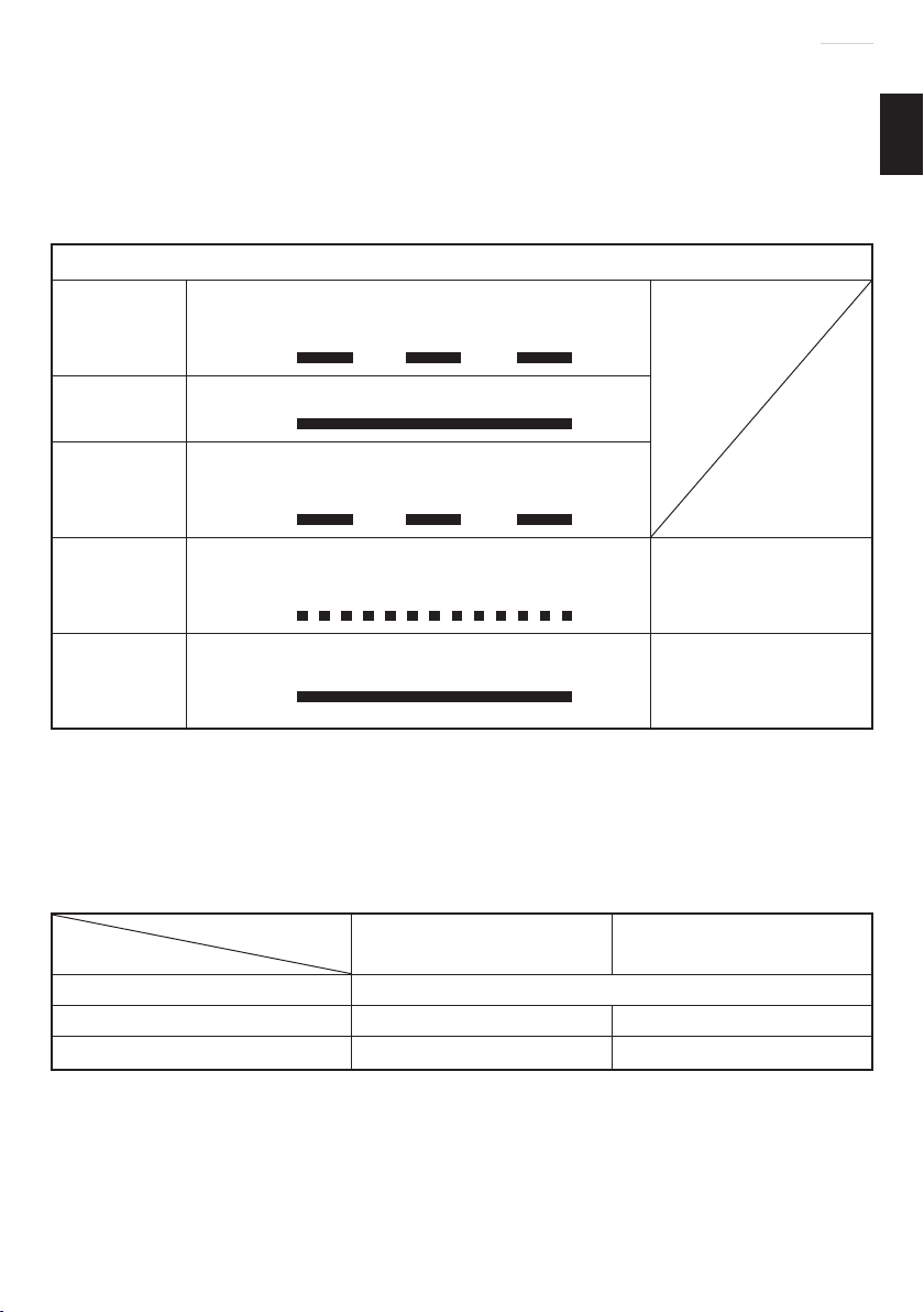
(1) 指示灯显示
根据充电器或电池的情况,指示灯的显示如表 1 所示。
表 1
指示灯的显示
充电前
充电时
充电完成
无法充电
过热而等待
注:
当等待冷却电池时,UC18YRL 通过冷却风扇使过热电池冷却。
(2) 关于电池的温度
电池的温度如下表所示,在充电前应使已发热的电池冷却片刻。
表 2 电池的充电范围
电池
镍镉电池 -5℃
镍氢电池 0℃
锂离子电池 x 0℃
4. 从电源插座拔下充电器的电源线
5. 握紧充电器并取出电池
注:
充电完成后,请先从充电器内取出电池,然后加以妥善保存。
闪烁
(红色)
点亮
(红色)
闪烁
(红色)
闪动
(红色)
点亮
(绿色)
点亮 0.5 秒钟,不点亮 0.5 秒钟
(熄灭 0.5 秒钟)
连续点亮
点亮 0.5 秒钟,不点亮 0.5 秒钟
(熄灭 0.5 秒钟)
点亮 0.1 秒钟,不点亮 0.1 秒钟
(熄灭 0.1 秒钟)
连续点亮
充电器
UC14YFA
UC24YFA
-
45℃ -5℃ - 50℃
电池或充电器有问
题。
电池过热。无法充
(电池冷却后开始进
行充电)。
UC18YRL
-
55℃
-
50℃
13

中文
注意!
○ 若在电池因长时间放置在受阳光直射的场所或刚使用后发热时进行充电,充
电器的指示灯点亮呈绿色。在此情况下,先将电池冷却后再开始充电。
○ 指示灯闪动呈红色时〔以 0.2 秒钟的间隔〕,请检查并取出充电器电池安装
孔内的任何异物。若无异物,则可能电池或充电器发生故障。请带去经授权
的维修中心检查。
○ 因内置的微机需要约 3 秒钟才能确认正用 UC14YFA,UC24YFA 和 UC18YRL
进行充电的电池已被取出,因此请待 3 秒钟后再重新插入电池继续充电。
〈UC18YG〉
使用充电式角向磨光机之前,请按照以下方法为电池充电。
1. 将充电器的电源线插头插入插座
接好电源线后便开始充电。
2. 将电池插入充电器
按正确的电极方向插入电池直至其接触到充电器底部(此时指示灯亮起)。
注意!
如果指示灯不亮,则请从插座上拔出电源线插头并检查电池的安装情况。
指示灯熄灭表示电池已经充好。
如果温度或电源电压偏低,电池充电时间则会延长。
如果充电已超过超过 120 分而指示灯仍不熄灭,则应停止充电并与您的日立
授权维修中心联系。
注意!
作业停止后,如电池(因晒太阳等原因)而变热,充电指示灯会不亮。这时,
应先让电池冷却,然后再充电。
3. 从电源插座拔下充电器的电源线
4. 握紧充电器并取出电池
关于新电池等的放电
因新的和长期未使用的电池内部的化学物质无活性,故第一次和第二次使用
-
时其放电能力可能较低。这是暂时现象,这种电池充电 2
其充电所需的正常时间。
较长时间保持电池性能的方法
(1) 在电池电力完全耗尽之前进行充电。
感到电动工具的能力变弱时,请停止使用并给电池充电。若您继续使用电动
工具并耗尽电力,电池可能会损坏或其使用寿命缩短。
14
3 次后即可恢复

中文
(2) 避免在高温环境中充电。
使用后电池的温度将迅速升高。若使用后立即对这种电池进行充电,其内部
化学物质会劣化,电池使用寿命将缩短。请稍等片刻,待电池冷却后再进行
充电。
作业之前
1. 工作环境的准备和检查
请确认工作环境确实附加注意事项中所规定的所有条件。
2. 电池的检查
请确认电池是否装紧了。如电池稍有松驰,则电池可能会掉出来而引起事故。
3. 安装并调整轮罩
轮罩是一种保护装置用来防止作业中因砂轮破裂而受伤。开始研磨作业之前,
请确认轮罩是否安装得紧固妥善。稍微拧松固定螺丝后,即可转动轮罩并将
其固定在所需角度,以得到最大工作效率。调整好轮罩后,必须确认固定螺
丝是否完全拧紧。
4. 确保所安装的砂轮和节点已按照厂家的使用说明固定。确保要使用的砂轮属
于正确类型、没有裂纹或表面缺陷。同时也要确认砂轮装好,轮螺母紧固。
参照“砂轮的组装与分解”一节。
确保使用随研磨产品附带的吸油纸或在需要时使用吸油纸。
请勿将独立的减速轴衬或接头,以便使用大孔砂轮。
有关要用螺纹孔砂轮来安装的工具,确保砂轮的螺纹足够长,以适合轴长。
请勿使用切断砂轮进行侧面研磨。
5. 试行运转
在使用前确保已正确安装并拧紧研磨产品,并在安全场所在空载状态下运转
30 秒钟,若有较大的振动或察觉到其他缺陷,则应立即停止试运转。遇此
情况时,检查电动工具以究明原因。
6. 检查按钮
在打开电源开关之前按两三下按钮,检查它是否已被释放。
7. 固定侧柄
把侧柄旋进齿轮罩。
实用角向磨光机的应用
1. 压力
本机不可施加过大压力使其过载,这样才能延长机器的使用寿命并确保加工
质量。在大部分的用法中,机器本身的重量即够研磨。加压过大将导致转速
降低、表面加工不良以及过载,从而使机器寿命缩短。
15

中文
2. 研磨角度
切勿将砂轮的全表面施加于要研磨的材
料上。如图 2 所示,机器应保持 15 30°,使砂轮的外缘以最佳角度与工件
相接触。
3. 用新砂轮首次进行研磨时,应将角向磨
光机由对面横过工件往操作人员这边
拉,以免挖入工件(图 2 的 B 方向)。
等砂轮的前缘适当磨损后,就可往任何
方向进行研磨。
4. 收工后的注意事项
在切断本电动工具的电源之后,砂轮仍会继续旋转一段时间。
关掉机器之后,需等角向磨光机完全停止才能将其放下,以免造成严重事故,
而且还可以减少吸入机器的尘埃及切屑量。
注:
○
为防止受伤,本产品有一项功能,可防止在插入电池时马达意外旋转。当开
关处于开启(ON)位置时,如果插入电池,马达将不运转。安装电池后,将
开关转到关闭(OFF)位置,然后重新转回到开启(ON)位置。
○
G14DL 和 G18DL 两个型号具有一项保护功能,该功能可在过载时关闭工具。
一旦工具因为过载而关闭,可以关闭然后重新打开电源。
如果一种负载使工具停止运行并持续 10 秒以上,则关闭然后重新打开电源
也无法释放该负载。一旦发生这种情况,从工具中取出后重新装入电池,然
后再打开电源开关。
A B
图 2
15° — 30°
注意!
○
检查工件已被正确固定。
○
在多尘的条件下工作时,确保通风口畅通无堵塞现象。
如果需要清除灰尘,首先使电动工具断开电源(使用非金属物品)并避免损
坏内部零件。
○
确保使用时产生的火花不会引起危险:例如,不要溅在身体上或点燃易燃物。
○
始终采用视力和听力保护。
必要时应使用其他个人保护装置,如口罩、手套、头盔和围裙等。
拿不准时,请使用保护装置。
○
未使用本电动工具时,请断开电池。
16

砂轮的组装与分解(图 3)
注意!
请务必关闭开关并取出电池。
中文
1. 组装(图 3)
(1) 将角向磨光机的上部朝下,以使主轴朝
上。
(2) 将砂轮垫圈的十字平面对准主轴的缺
口部分,然后装上它们。
(3) 将砂轮的突起部安装在砂轮垫圈上。
(4) 将砂轮螺帽拧在主轴上。
(5) 用一只手按下按钮,同时用另一只手慢
慢地转动砂轮以卡紧主轴。
如图 3 所示,用附带的扳手拧紧砂轮
螺帽。
2. 分解
分解顺序与安装顺序相反。
扳手
砂轮螺帽
砂轮
砂轮垫圈
主轴
砂轮保护
装置
金刚石轮
按钮
图 3
注意!
○
请确认砂轮是否安装紧固。
○
请在打开电源开关之前,按两三下按钮,以确认按钮是否已被释放。
维护和检查
1. 检查砂轮
检查砂轮确无破裂和表面缺陷。
2. 检查安装螺钉
要经常检查安装螺钉是否紧固妥善。若发现螺
钉松了,应立即重新扭紧,否则会导致严重的
事故。
3. 电动机的维护
电动机绕线是电动工具的心脏部。应仔细检查有无损伤,是否被油液或水沾
湿。
4. 检查炭刷(图 4)
马达使用炭刷这种消耗品。因过度磨损的炭刷会导致马达发生故障,因此,
当炭刷磨损或接近“磨损极限”时,请换上新的炭刷。此外,请始终保持炭
刷的清洁,并确保它能在炭刷盒里自由滑动。
注:
换上新的炭刷时,请一定使用日立牌炭刷(代码号 :999054)。
磨耗极限
3mm
11.5mm
图 4
17

中文
5. 更换炭刷
如图 6 所示,先取下刷帽,然后用平头螺丝刀
等钩住炭刷的突起部分,取出炭刷。
安装炭刷时,选择方向,使炭刷钉对准炭刷管
外面的连接部分。如图 7 所示,用手指将其推
入。最后安装刷帽。
注意!
务请将炭刷钉插入炭刷管外面的连接部分。(可
插入附带的两个炭刷钉中的任何一个)。
须特别注意,因为操作的任何差错均会导致炭
刷钉变形,并且可能在很早的阶段就导致马达
发生故障。
6. 清理外部
充电式角向磨光机沾污时,用软布或沾肥皂水
的布擦拭。不要使用氯溶液、汽油或稀释剂。
7. 存放
请存放在温度低于 40℃ 并远离小孩的场所。
8. 维修零部件一览表
炭刷钉
炭刷突起
图 5
图 6
注意!
日立牌电动工具的维修、改造和检查须由经日
立公司授权的维修中心进行。
当要求维修或其他保养服务时,若将此零部件
一览表与电动工具一起呈交给经日立公司授权的维修中心,将有助于维修或
保养工作。
在操作和维修电动工具时,必须遵守贵国制定的安全的有关规则和标准。
炭刷管外侧连接部分
图 7
关于日立牌无线电动工具的重要通知 :
请确保始终使用我们指定的正版电池。如果使用我们指定以外的电池,或对
电池进行拆卸和改动(例如拆卸和更换电池组件或其他内部部件),那么我们
无法保证我们无线电动工具的安全性和使用性能。
18

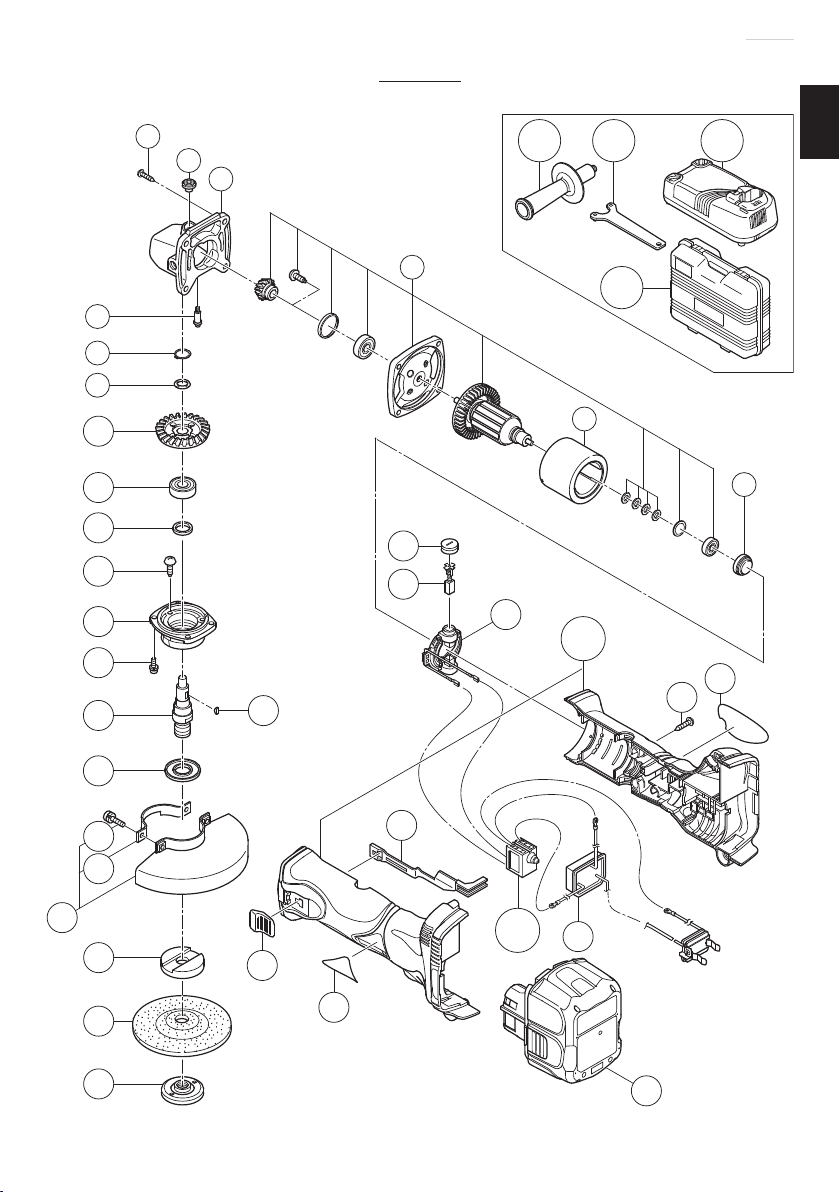
维修零部件一览表
中文
G14DMR
7
8
9
10
11
12
13
14
15
16
1
2
3
4
25
26
24
501 502
504
5
27
28A
503
6
29
37
20
17
18
19
21
22
23
32
33
31
19
34A
35
36

中文
项目号 代码号 使用数 备注
1 328643 4 D4×23
2 301944 1
3 303078 1 “2, 7”
4 360803 1
5 328195 1
6 328201 1
7 301943 1
8 316487 1
9 316486 1
10 328196 1
11 6001VV 1
12 301946 1
13 301936 3 M4×10
14 328198 1
15 307127 4 M4×12
16 328359 1 M14
17 301945 1
18 308386 2 M5×16
19 301949 1
20 315492 1 “18, 19”
21 937817Z 1
22 316821 1 115MM
23 994324 1 M14
24 302047 1
25 328200 2
26 999054 2 5×6×11.5
27 328202 1
28A 329059 1
29 ––––––– 1
31 328199 1
32 314428 1
33 ––––––– 1
34A 329057 1
6001VVCMPS2L
A36Q
项目号 代码号 使用数 备注
35 328658 1
36 315130 2 EB14B
37 301653 5 D4×20
501 318312 1
502 938332Z 1
503 ––––––– 1 UC18YG
504 328206 1
20
G14DL
中文
7
8
9
10
11
12
13
14
15
16
1
2
3
4
504
5
25
26
27
28A
24
503501 502
6
29
37
20
17
18
19
21
22
23
32
33
31
21
34A
35
36

中文
项目号 代码号 使用数 备注
1 328643 4 D4×23
2 301944 1
3 303078 1 “2, 7”
4 360803 1
5 328195 1
6 328201 1
7 301943 1
8 316487 1
9 316486 1
10 328196 1
11 6001VV 1
12 301946 1
13 301936 3 M4×10
14 328198 1
15 307127 4 M4×12
16 328359 1 M14
17 301945 1
18 308386 2 M5×16
19 301949 1
20 315492 1 “18, 19”
21 937817Z 1
22 316821 1 115MM
23 994324 1 M14
24 302047 1
25 328200 2
26 999054 2 5×6×11.5
27 328202 1
28A 329059 1
29 ––––––– 1
31 328199 1
32 314428 1
33 ––––––– 1
34A 329057 1
6001VVCMPS2L
A36Q
项目号 代码号 使用数 备注
35 328658 1
36 326824 2 BCL1430
37 301653 5 D4×20
501 318312 1
502 938332Z 1
503 ––––––– 1 UC18YRL
504 328206 1
22

G18DMR
中文
7
8
9
10
11
12
13
14
15
16
1
2
3
4
25
26
24
501 502
504
5
27
28A
37
503
6
29
20
17
18
19
21
22
23
32
33
31
23
34A
35
36

中文
项目号 代码号 使用数 备注
1 328643 4 D4×23
2 301944 1
3 303078 1 “2, 7”
4 360804 1
5 328195 1
6 328201 1
7 301943 1
8 316487 1
9 316486 1
10 328364 1
11 6001VV 1
12 301946 1
13 301936 3 M4×10
14 328198 1
15 307127 4 M4×12
16 328359 1 M14
17 301945 1
18 308386 2 M5×16
19 301949 1
20 315492 1 “18, 19”
21 937817Z 1
22 316821 1 115MM
23 994324 1 M14
24 302047 1
25 328200 2
26 999054 2 5×6×11.5
27 328202 1
28A 329060 1
29 ––––––– 1
31 328199 1
32 314428 1
33 ––––––– 1
34A 329057 1
6001VVCMPS2L
A36Q
项目号 代码号 使用数 备注
35 328658 1
36 322880 2 EB1820L
37 301653 5 D4×20
501 318312 1
502 938332Z 1
503 ––––––– 1 UC18YG
504 328206 1
24

G18DL
中文
7
8
9
10
11
12
13
14
15
16
1
2
3
4
504
5
25
26
27
28A
24
503501 502
6
29
37
20
17
18
19
21
22
23
32
33
31
25
34A
35
36

中文
项目号 代码号 使用数 备注
1 328643 4 D4×23
2 301944 1
3 303078 1 “2, 7”
4 360804 1
5 328195 1
6 328201 1
7 301943 1
8 316487 1
9 316486 1
10 328364 1
11 6001VV 1
12 301946 1
13 301936 3 M4×10
14 328198 1
15 307127 4 M4×12
16 328359 1 M14
17 301945 1
18 308386 2 M5×16
19 301949 1
20 315492 1 “18, 19”
21 937817Z 1
22 316821 1 115MM
23 994324 1 M14
24 302047 1
25 328200 2
26 999054 2 5×6×11.5
27 328202 1
28A 329060 1
29 ––––––– 1
31 328199 1
32 314428 1
33 ––––––– 1
34A 329057 1
6001VVCMPS2L
A36Q
项目号 代码号 使用数 备注
35 328658 1
36 326240 2 EBM1830
37 301653 5 D4×20
501 318312 1
502 938332Z 1
503 ––––––– 1 UC18YRL
504 328206 1
26

English
CONTENTS
GENERAL POWER TOOL SAFETY WARNINGS ........................................ 27
SAFETY WARNINGS COMMON FOR GRINDING OR ABRASIVE
CUTTING-OFF OPERATIONS .....................................................................30
KICKBACK AND RELATED WARNINGS ..................................................... 31
SAFETY WARNINGS SPECIFIC FOR GRINDING AND ABRASIVE
CUTTING-OFF OPERATIONS .....................................................................32
ADDITIONAL SAFETY WARNINGS SPECIFIC FOR ABRASIVE
CUTTING-OFF OPERATIONS .....................................................................32
GENERAL SAFETY INSTRUCTIONS FOR CORDLESS DISC
GRINDERS ................................................................................................... 33
CAUTION ON LITHIUM-ION BATTERY .......................................................34
SYMBOL .......................................................................................................35
SPECIFICATIONS ........................................................................................ 36
STANDARD ACCESSORIES ....................................................................... 37
APPLICATIONS ............................................................................................38
BATTERY REMOVAL/INSTALLATION ........................................................38
CHARGING ..................................................................................................38
PRIOR TO OPERATION ............................................................................... 41
PRACTICAL GRINDER APPLICATION ........................................................ 42
ASSEMBLING AND DISASSEMBLING THE DEPRESSED CENTER WHEEL
MAINTENANCE AND INSPECTION ............................................................43
SERVICE PARTS LIST ................................................................................. 46
... 43
GENERAL POWER TOOL SAFETY WARNINGS
WARNING
Read all safety warnings and all instructions.
Failure to follow the warnings and instructions may result in electric shock, fi re and/or serious
injury.
Save all warnings and instructions for future reference.
The term “power tool” in the warnings refers to your mains-operated (corded) power tool or
battery-operated (cordless) power tool.
1) Work area safety
a) Keep work area clean and well lit.
Cluttered or dark areas invite accidents.
b) Do not operate power tools in explosive atmospheres, such as in the presence
of fl ammable liquids, gases or dust.
Power tools create sparks which may ignite the dust or fumes.
c) Keep children and bystanders away while operating a power tool.
Distractions can cause you to lose control.
27

English
2) Electrical safety
a) Power tool plugs must match the outlet.
Never modify the plug in any way.
Do not use any adapter plugs with earthed (grounded) power tools.
Unmodifi ed plugs and matching outlets will reduce risk of electric shock.
b) Avoid body contact with earthed or grounded surfaces, such as pipes,
radiators, ranges and refrigerators.
There is an increased risk of electric shock if your body is earthed or grounded.
c) Do not expose power tools to rain or wet conditions.
Water entering a power tool will increase the risk of electric shock.
d) Do not abuse the cord. Never use the cord for carrying, pulling or unplugging
the power tool.
Keep cord away from heat, oil, sharp edges or moving parts.
Damaged or entangled cords increase the risk of electric shock.
e) When operating a power tool outdoors, use an extension cord suitable for
outdoor use.
Use of a cord suitable for outdoor use reduces the risk of electric shock.
f) If operating a power tool in a damp location is unavoidable, use a residual
current device (RCD) protected supply.
Use of an RCD reduces the risk of electric shock.
3) Personal safety
a) Stay alert, watch what you are doing and use common sense when operating a
power tool.
Do not use a power tool while you are tired or under the infl uence of drugs,
alcohol or medication.
A moment of inattention while operating power tools may result in serious personal
injury.
b) Use personal protective equipment. Always wear eye protection.
Protective equipment such as dust mask, non-skid safety shoes, hard hat, or hearing
protection used for appropriate conditions will reduce personal injuries.
c) Prevent unintentional starting. Ensure the switch is in the off position before
connecting to power source and/or battery pack, picking up or carrying the
tool.
Carrying power tools with your fi nger on the switch or energising power tools that have
the switch on invites accidents.
d) Remove any adjusting key or wrench before turning the power tool on.
A wrench or a key left attached to a rotating part of the power tool may result in
personal injury.
e) Do not overreach. Keep proper footing and balance at all times.
This enables better control of the power tool in unexpected situations.
f) Dress properly. Do not wear loose clothing or jewellery. Keep your hair,
clothing and gloves away from moving parts.
Loose clothes, jewellery or long hair can be caught in moving parts.
28

English
g) If devices are provided for the connection of dust extraction and collection
facilities, ensure these are connected and properly used.
Use of dust collection can reduce dust-related hazards.
4) Power tool use and care
a) Do not force the power tool. Use the correct power tool for your application.
The correct power tool will do the job better and safer at the rate for which it was
designed.
b) Do not use the power tool if the switch does not turn it on and off .
Any power tool that cannot be controlled with the switch is dangerous and must be
repaired.
c) Disconnect the plug from the power source and/or the battery pack from the
power tool before making any adjustments, changing accessories, or storing
power tools.
Such preventive safety measures reduce the risk of starting the power tool accidentally.
d) Store idle power tools out of the reach of children and do not allow persons
unfamiliar with the power tool or these instructions to operate the power tool.
Power tools are dangerous in the hands of untrained users.
e) Maintain power tools. Check for misalignment or binding of moving parts,
breakage of parts and any other condition that may aff ect the power toolʼs
operation.
If damaged, have the power tool repaired before use.
Many accidents are caused by poorly maintained power tools.
f) Keep cutting tools sharp and clean.
Properly maintained cutting tools with sharp cutting edges are less likely to bind and
are easier to control.
g) Use the power tool, accessories and tool bits etc. in accordance with these
instructions, taking into account the working conditions and the work to be
performed.
Use of the power tool for operations diff erent from those intended could result in a
hazardous situation.
5) Battery tool use and care
a) Recharge only with the charger specifi ed by the manufacturer.
A charger that is suitable for one type of battery pack may create a risk of fi re when
used with another battery pack.
b) Use power tools only with specifi cally designated battery packs.
Use of any other battery packs may create a risk of injury and fi re.
c) When battery pack is not in use, keep it away from other metal objects, like
paper clips, coins, keys, nails, screws or other small metal objects, that can
make a connection from one terminal to another.
Shorting the battery terminals together may cause burns or a fi re.
d) Under abusive conditions, liquid may be ejected from the battery; avoid
contact. If contact accidentally occurs, fl ush with water. If liquid contacts eyes,
additionally seek medical help.
Liquid ejected from the battery may cause irritation or burns.
29

English
6) Service
a) Have your power tool serviced by a qualifi ed repair person using only identical
replacement parts.
This will ensure that the safety of the power tool is maintained.
CAUTION
Keep children and infi rm persons away.
When not in use, tools should be stored out of reach of children and infi rm persons.
SAFETY WARNINGS COMMON FOR GRINDING OR
ABRASIVE CUTTING-OFF OPERATIONS
a) This power tool is intended to function as a grinder or cut-off tool. Read all safety
warnings, instructions, illustrations and specifi cations provided with this power
tool.
Failure to follow all instructions listed below may result in electric shock, fi re and/or serious
injury.
b) Operations such as sanding, wire brushing or polishing are not recommended to
be performed with this power tool.
Operations for which the power tool was not designed may create a hazard and cause
personal injury.
c) Do not use accessories which are not specifi cally designed and recommended by
the tool manufacturer.
Just because the accessory can be attached to your power tool, it does not assure safe
operation.
d) The rated speed of the accessory must be at least equal to the maximum speed
marked on the power tool.
Accessories running faster than their rated speed can break and fl y apart.
e) The outside diameter and the thickness of your accessory must be within the
capacity rating of your power tool.
Incorrectly sized accessories cannot be adequately guarded or controlled.
f) The arbour size of wheels, fl anges, backing pads or any other accessory must
properly fi t the spindle of the power tool.
Accessories with arbour holes that do not match the mounting hardware of the power tool
will run out of balance, vibrate excessively and may cause loss of control.
g) Do not use a damaged accessory. Before each use inspect the accessory such
as abrasive wheels for chips and cracks, backing pad for cracks, tear or excess
wear, wire brush for loose or cracked wires. If power tool or accessory is dropped,
inspect for damage or install an undamaged accessory. After inspecting and
installing an accessory, position yourself and bystanders away from the plane of
the rotating accessory and run the power tool at maximum no-load speed for one
minute.
Damaged accessories will normally break apart during this test time.
30

English
h) Wear personal protective equipment. Depending on application, use face shield,
safety goggles or safety glasses. As appropriate, wear dust mask, hearing
protectors, gloves and workshop apron capable of stopping small abrasive or
workpiece fragments.
The eye protection must be capable of stopping fl ying debris generated by various
operations. The dust mask or respirator must be capable of fi ltrating particles generated by
your operation.
Prolonged exposure to high intensity noise may cause hearing loss.
i) Keep bystanders a safe distance away from work area. Anyone entering the work
area must wear personal protective equipment.
Fragments of workpiece or of a broken accessory may fl y away and cause injury beyond
immediate area of operation.
j) Hold power tool by insulated gripping surfaces only, when performing an operation
where the cutting accessory may contact hidden wiring or its own cord.
Cutting accessory contacting a “live” wire may make exposed metal parts of the power tool
“live” and shock the operator.
k) Position the cord clear of the spinning accessory.
If you lose control, the cord may be cut or snagged and your hand or arm may be pulled
into the spinning accessory.
l) Never lay the power tool down until the accessory has come to a complete stop.
The spinning accessory may grab the surface and pull the power tool out of your control.
m) Do not run the power tool while carrying it at your side.
Accidental contact with the spinning accessory could snag your clothing, pulling the
accessory into your body.
n) Regularly clean the power tool’s air vents.
The motor’s fan will draw the dust inside the housing and excessive accumulation of
powdered metal may cause electrical hazards.
o) Do not operate the power tool near fl ammable materials.
Sparks could ignite these materials.
p) Do not use accessories that require liquid coolants.
Using water or other liquid coolants may result in electrocution or shock.
KICKBACK AND RELATED WARNINGS
Kickback is a sudden reaction to a pinched or snagged rotating wheel, backing pad,
brush or any other accessory. Pinching or snagging causes rapid stalling of the rotating
accessory which in turn causes the uncontrolled power tool to be forced in the direction
opposite of the accessory’s rotation at the point of the binding.
For example, if an abrasive wheel is snagged or pinched by the workpiece, the edge of
the wheel that is entering into the pinch point can dig into the surface of the material
causing the wheel to climb out or kick out. The wheel may either jump toward or away
from the operator, depending on direction of the wheel’s movement at the point of
pinching. Abrasive wheels may also break under these conditions.
Kickback is the result of power tool misuse and/or incorrect operating procedures or
conditions and can be avoided by taking proper precautions as given below.
31

English
a) Maintain a fi rm grip on the power tool and position your body and arm to allow you
to resist kickback forces. Always use auxiliary handle, if provided, for maximum
control over kickback or torque reaction during start-up.
The operator can control torque reactions or kickback forces, if proper precautions are
taken.
b) Never place your hand near the rotating accessory.
Accessory may kickback over your hand.
c) Do not position your body in the area where power tool will move if kickback
occurs.
Kickback will propel the tool in direction opposite to the wheel’s movement at the point of
snagging.
d) Use special care when working corners, sharp edges etc. Avoid bouncing and
snagging the accessory.
Corners, sharp edges or bouncing have a tendency to snag the rotating accessory and
cause loss of control or kickback.
e) Do not attach a saw chain woodcarving blade or toothed saw blade.
Such blades create frequent kickback and loss of control.
SAFETY WARNINGS SPECIFIC FOR GRINDING AND
ABRASIVE CUTTING-OFF OPERATIONS
a) Use only wheel types that are recommended for your power tool and the specifi c
guard designed for the selected wheel.
Wheels for which the power tool was not designed cannot be adequately guarded and are
unsafe.
b) The guard must be securely attached to the power tool and positioned for
maximum safety, so the least amount of wheel is exposed towards the operator.
The guard helps to protect operator from broken wheel fragments and accidental contact
with wheel.
c) Wheels must be used only for recommended applications. For example: do not
grind with the side of cut-off wheel.
Abrasive cut-off wheels are intended for peripheral grinding, side forces applied to these
wheels may cause them to shatter.
d) Always use undamaged wheel fl anges that are of correct size and shape for your
selected wheel.
Proper wheel fl anges support the wheel thus reducing the possibility of wheel breakage.
Flanges for cut-off wheels may be diff erent from grinding wheel fl anges.
e) Do not use worn down wheels from larger power tools.
Wheel intended for larger power tool is not suitable for the higher speed of a smaller tool
and may burst.
ADDITIONAL SAFETY WARNINGS SPECIFIC FOR
ABRASIVE CUTTING-OFF OPERATIONS
a) Do not “jam” the cut-off wheel or apply excessive pressure. Do not attempt to make
an excessive depth of cut.
32

English
Overstressing the wheel increases the loading and susceptibility to twisting or blinding of
the wheel in the cut and the possibility of kickback or wheel breakage.
b) Do not position your body in line with and behind the rotating wheel.
When the wheel, at the point of operation, is moving away from your body, the possible
kickback may propel the spinning wheel and the power tool directly at you.
c) When wheel is binding or when interrupting a cut for any reason, switch off the
power tool and hold the power tool motionless until the wheel comes to a complete
stop. Never attempt to remove the cut-off wheel from the cut while the wheel is in
motion otherwise kickback may occur.
Investigate and take corrective action to eliminate the cause of wheel binding.
d) Do not restart the cutting operation in the workpiece. Let the wheel reach full speed
and carefully reenter the cut.
The wheel may bind, walk up or kickback if the power tool is restarted in the workpiece.
GENERAL SAFETY INSTRUCTIONS FOR CORDLESS
DISC GRINDERS
— Check that speed marked on the wheel is equal to or greater than the rated speed
of the grinder;
— Ensure that the wheel dimensions are compatible with the grinder;
— Abrasive wheels shall be stored and handled with care in accordance with
manufacturer’s instructions;
— Inspect the grinding wheel before use, do not use chipped, cracked or otherwise
defective products;
— Ensure that mounted wheels and points are fi tted in accordance with the
manufacturer’s instructions;
— Ensure that blotters are used when they are provided with the bonded abrasive
product and when they are required;
— Ensure that the abrasive product is correctly mounted and tightened before use
and run the tool at no-load for 30 s in a safe position, stop immediately if there is
considerable vibration or if other defects are detected. If this condition occurs,
check the machine to determine the cause;
— If a guard is equipped with the tool never use the tool without such a guard;
— Do not use separate reducing bushings or adapters to adapt large hole abrasive
wheels;
— For tools intended to be fi tted with threaded hole wheel, ensure that the thread in
the wheel is long enough to accept the spindle length;
— Check that the work piece is properly supported;
— Do not use cutting off wheel for side grinding;
— Ensure that sparks resulting from use do not create a hazard e.g. do not hit
persons, or ignite fl ammable substances;
— Ensure that ventilation openings are kept clear when working in dusty conditions, if
it should become necessary to clear dust, fi rst disconnect the tool from the mains
supply (use non metallic objects) and avoid damaging internal parts;
33

English
— Always use eye and ear protection. Other personal protective equipment such as
dust mask, gloves, helmet and apron should be worn;
— Pay attention to the wheel that continues to rotate after the tool is switched off .
— Always charge the battery at a temperature of 0 – 40°C.
A temperature of less than 0°C will result in over charging which is dangerous. The
battery cannot be charged at a temperature greater than 40°C.
The most suitable temperature for charging is that of 20 – 25°C.
— Do not use the charger continuously.
When one charging is completed, leave the charger for about 15 minutes before
the next charging of battery.
— Do not allow foreign matter to enter the hole for connecting the battery.
— Never disassemble the battery and charger.
— Never short-circuit the battery.
Short-circuiting the battery will cause a great electric current and overheat. It
results in burn or damage to the battery.
— Do not dispose of the battery in fi re.
If the battery burnt, it may explode.
— Do not insert object into the air ventilation slots of the charger.
Inserting metal objects or infl ammables into the charger air ventilation slots will
result in electrical shock hazard or damaged charger.
— Bring the battery to the shop from which it was purchased as soon as the post-
charging battery life becomes too short for practical use. Do not dispose of the
exhausted battery.
— Using an exhausted battery will damage the charger.
CAUTION ON LITHIUM-ION BATTERY
To extend the lifetime, the lithium-ion battery equips with the protection function to stop
the output.
In the cases of 1 and 2 described below, when using this product, even if you are pulling
the switch, the motor may stop. This is not the trouble but the result of protection
function.
1. When the battery power remaining runs out (The battery voltage drops to about
12V (G18DL) / about 8V (G14DL)), the motor stops.
In such case, charge it up immediately.
2. If the tool is overloaded, the motor may stop. In this case, release the switch of tool
and eliminate causes of overloading. After that, you can use it again.
Furthermore, please heed the following warning and caution.
WARNING
In order to prevent any battery leakage, heat generation, smoke emission, explosion and
ignition beforehand, please be sure to heed the following precautions.
1. Make sure that swarf and dust do not collect on the battery.
○
During work make sure that swarf and dust do not fall on the battery.
○
Make sure that any swarf and dust falling on the power tool during work do not
collect on the battery.
34

English
○
Do not store an unused battery in a location exposed to swarf and dust.
○
Before storing a battery, remove any swarf and dust that may adhere to it and do
not store it together with metal parts (screws, nails, etc.).
2. Do not pierce battery with a sharp object such as a nail, strike with a hammer, step
on, throw or subject the battery to severe physical shock.
3. Do not use an apparently damaged or deformed battery.
4. Do not use the battery in reverse polarity.
5. Do not connect directly to an electrical outlets or car cigarette lighter sockets.
6. Do not use the battery for a purpose other than those specifi ed.
7. If the battery charging fails to complete even when a specifi ed recharging time has
elapsed, immediately stop further recharging.
8. Do not put or subject the battery to high temperatures or high pressure such as
into a microwave oven, dryer, or high pressure container.
9. Keep away from fi re immediately when leakage or foul odor are detected.
10. Do not use in a location where strong static electricity generates.
11. If there is battery leakage, foul odor, heat generated, discolored or deformed, or in
any way appears abnormal during use, recharging or storage, immediately remove
it from the equipment or battery charger, and stop use.
CAUTION
1. If liquid leaking from the battery gets into your eyes, do not rub your eyes and
wash them well with fresh clean water such as tap water and contact a doctor
immediately.
If left untreated, the liquid may cause eye-problems.
2. If liquid leaks onto your skin or clothes, wash well with clean water such as tap
water immediately.
There is a possibility that this can cause skin irritation.
3. If you fi nd rust, foul odor, overheating, discolor, deformation, and/or other
irregularities when using the battery for the fi rst time, do not use and return it to
your supplier or vendor.
SYMBOL
WARNING
The following show symbols used for the machine. Be sure that you understand their
meaning before use.
Read all safety warnings and all instructions.
35

English
SPECIFICATIONS
Cordless disc grinder
Model G14DMR G14DL G18DMR G18DL
Voltage 14.4 V 18 V
No-Load speed 9300 /min 9100 /min
Wheel
Battery
Weight
Charger
Model UC14YFA UC24YFA UC18YG UC18YRL
Charging voltage 7.2 – 14.4 V 7.2 – 24 V 7.2 – 18 V 7.2 – 18 V
Charging time
Weight 0.6 kg 0.6 Kg 0.3 Kg 0.6 Kg
outer dia. × hole dia. 115 × 22.23 mm
peripheral speed 80 m/s
2.0 Ah
2.6 Ah
3.0 Ah
3.3 Ah
2.0 Ah : Ni-Cd 50 min. 50 min. 50 min. 30 min.
2.6 Ah : Ni-MH 65 min. 65 min. x 40 min.
3.0 Ah : Ni-MH 70 min. 70 min. x 45 min.
3.3 Ah : Ni-MH 75 min. 75 min. x 50 min.
3.0 Ah : Li-ion x x x 45 min.
EB14B: Ni-Cd
(12 cells)
EB1426H:
Ni-MH (12 cells)
BCL1430: Li-ion
EB1430H:
Ni-MH (12 cells)
EB1433X:
Ni-MH (12 cells)
2.1 Kg 1.8 Kg 2.3 Kg 1.9 Kg
EBL1430: Li-ion
x
x
(4 or 8 cells)
(4 cells)
x
EB1820L: Ni-Cd
(15 cells)
EB1826H:
Ni-MH (15 cells)
EB1830H:
Ni-MH (15 cells)
EB1833X:
Ni-MH (15 cells)
x
x
EBM1830:
Li-ion (10 cells)
x
Charge time is approximate. Actual charge time may vary.
“x” Indicates that the battery pack is not compatible with that specifi c charger.
36

English
STANDARD ACCESSORIES
In addition to the main unit (1 unit), the package contains the accessories listed in the below.
G14DMR (NN)
G14DMR
(2BGK)
G14DL
G18DMR
(2LRK)
(2BGK)
(2MRK)
G18DL
G14DMR
(BGK)
G14DL
G18DMR
(MRK)
(BGK)
G18DL
G14DL (NN)
(MRK)
G18DMR (NN)
G18DL (NN)
Depressed
center wheel
Wrench
Side handle
Plastic case
Charger
(UC18YG)
Charger
(UC18YRL)
Battery
(EB14B)
Battery
(BCL1430)
11111111 1
11111111 1
11111111 1
11111111 1
1—1—1—1— —
—1—1—1—1 —
2 ——— 1 ——— —
—2———1—— —
Battery
(EB1820L)
Battery
(EBM1830)
——2———1— —
——— 2 ——— 1 —
37

English
APPLICATIONS
○
Removal of casting fi n and fi nishing of various types of steel, bronze and aluminum
materials and castings.
○
Grinding of welded sections or sections cut by means of a cutting torch.
○
Grinding of synthetic resins, slate, brick, marble, etc.
○
Cutting of synthetic concrete, stone, brick, marble, and similar materials.
BATTERY REMOVAL/INSTALLATION
1. Battery removal
Hold the handle tightly and push the battery latch to remove the
battery (See Fig. 1).
Battery
Latch
CAUTION
Never short-circuit the battery.
2. Battery installation
Insert the battery while observing its polarities (See Fig. 1).
Insert
Fig. 1
Pull out
CHARGING
〈UC14YFA, UC24YFA, UC18YRL〉
Before using the cordless disc grinder, charge the battery as follows.
1. Connect the charger’s power cord to a receptacle
When the power cord is connected, the charger’s pilot lamp will blink in red (At 1-second
intervals).
2. Insert the battery into the charger
Insert the battery fi rmly, until it contacts the bottom of the charger compartment.
CAUTION
If the battery is inserted in the reverse direction, not only recharging will become
impossible, but it may also cause problems in the charger such as deformed
recharging terminal.
3. Charging
When inserting a battery in the charger, charging will commence and the pilot lamp will light
up continuously in red.
When the battery becomes fully recharged, the pilot lamp will blink in red (At 1-second
intervals) (See Table 1).
(1) Pilot lamp indication
The indications of the pilot lamp will be as shown in Table 1, according to the condition of
the charger or the battery.
38

Before
charging
Blinks
(RED)
English
Table 1
Indications of the lamps
Lights for 0.5 seconds. Does not light
for 0.5 seconds. (off for 0.5 seconds)
While
charging
Charging
complete
Charging
impossible
Overheat
standby
NOTE
When standby for cooling battery, UC18YRL cools the overheated battery by cooling fan.
(2) Regarding the temperatures of the battery
The temperatures for batteries are as shown in the table below, and batteries that have
become hot should be cooled for a while before being recharged.
Table 2 Recharging ranges of batteries
Batteries
Ni-Cd batteries –5°C – 55°C
Ni-MH batteries 0°C – 45°C –5°C – 50°C
Li-ion batteries x 0°C – 50°C
Lights
(RED)
Blinks
(RED)
Flickers
(RED)
Lights
(GREEN)
Lights continuously
Lights for 0.5 seconds. Does not light
for 0.5 seconds. (off for 0.5 seconds)
Lights for 0.1 seconds. Does not light
for 0.1 seconds. (off for 0.1 seconds)
Lights continuously
Charger
UC14YFA
UC24YFA
Malfunction in the battery or
the charger.
Battery overheated.
Unable to charge
(Charging will commence
when battery cools).
UC18YRL
4. Disconnect the charger’s power cord from the receptacle
5. Hold the charger fi rmly and pull out the battery
NOTE
Be sure to pull out the battery from the charger after use, and then keep it.
CAUTION
○
If the battery is charged while it is heated because it has been left for a long time in
a location subject to direct sunlight or because the battery has just been used, the
pilot lamp of the charger lights up green. In such a case, fi rst let the battery cool,
then start charging.
39

English
○
When the pilot lamp fl ickers in red quickly (at 0.2-second intervals), check for and
take out any foreign objects in the charger’s battery installation hole. If there are no
foreign objects, it is probable that the battery or charger is malfunctioning. Take it
to your Authorized Service Center.
○
Since the built-in micro computer takes about 3 seconds to confi rm that the battery
being charged with UC14YFA, UC24YFA and UC18YRL are taken out, wait for a
minimum of 3 seconds before reinserting it to continue charging. If the battery is
reinserted within 3 seconds, the battery may not be properly charged.
〈UC18YG〉
Before using the cordless disc grinder, charge the battery as follows.
1. Connect the charger power cord to the receptacle
Connecting the power cord will turn on the charger.
2. Insert the battery into the charger
Insert the battery fi rmly while observing its direction, until it contacts the bottom of the
charger (the pilot lamp lights up).
CAUTION
If the pilot lamp does not light up, pull out the power cord from the receptacle and
check the battery mounting condition.
The pilot lamp goes off to indicate that the battery is fully charged.
The battery charging time becomes longer when a temperature is low or the voltage of the
power source is too low.
When the pilot lamp does not go off even if more than 120 minutes have elapsed after
starting of the charging, stop the charging and contact your HITACHI AUTHORIZED
SERVICE CENTER.
CAUTION
If the battery is heated due to direct sunlight, etc., just after operation, the charger
pilot lamp may not light up. At that time, cool the battery fi rst, then start charging.
3. Disconnect the charger power cord from the receptacle
4. Hold the charger tight and pull out the battery
Regarding electric discharge in case of new batteries, etc.
As the internal chemical substance of new batteries and batteries that have not been used
for an extended period is not activated, the electric discharge might be low when using
them the fi rst and second time. This is a temporary phenomenon, and normal time required
for recharging will be restored by recharging the batteries 2 – 3 times.
How to make the batteries perform longer
(1) Recharge the batteries before they become completely exhausted.
When you feel that the power of the tool becomes weaker, stop using the tool and recharge
its battery. If you continue to use the tool and exhaust the electric current, the battery may
be damaged and its life will become shorter.
40

English
(2) Avoid recharging at high temperatures.
A battery will be hot immediately after use. If such a battery is recharged immediately after
use, its internal chemical substance will deteriorate, and the battery life will be shortened.
Leave the battery and recharge it after it has cooled for a while.
PRIOR TO OPERATION
1. Preparing and checking the work environment
Make sure that the work site meets all the conditions laid forth in the precautions.
2. Checking the battery
Make sure that the battery is installed fi rmly. If it is at all loose it could come off and cause
an accident.
3. Fitting and adjusting the wheel guard
The wheel guard is a protective device to prevent injury should the depressed center
wheel shatter during operation. Ensure that the guard is properly fi tted and fastened before
commencing grinding operation. By slightly loosening the setting screw, the wheel guard
can be turned and set at any desired angle for maximum operational eff ectiveness. Ensure
that the setting screw is thoroughly tightened after adjusting the wheel guard.
4. Ensure that mounted wheels and points are fi tted in accordance with the manufacturer’s
instructions.
Ensure that the depressed center wheel to be utilized is the correct type and free of cracks
or surface defects. Also ensure that the depressed center wheel is properly mounted
and the wheel nut is securely tightened, Refer to the section on “ASSEMBLING AND
DISASSEMBLING THE DEPRESSED CENTER WHEEL”
Ensure that blotters are used when they are provided with the bonded abrasive product and
when they are required.
Do not use separate reducing bushings or adaptors to adapt large hole abrasive wheels.
For tools intended to be fi tted with threaded hole wheel, ensure that the thread in the wheel
is long enough to accept the spindle length.
Do not use cutting off wheel for side grinding.
5. Conducting a trial run
Ensure that the abrasive products is correctly mounted and tightened before use and
run the tool at no-load for 30 seconds in a safe position, stop immediately if there is
considerable vibration or if other defects are detected.
If this condition occurs, check the machine to determine the cause.
6. Confi rm the push button.
Confi rm that the push button is disengaged by pushing push button two or three times
before switching the power tool on.
7. Fixing the side handle.
Screw the side handle into the gear cover.
41

English
PRACTICAL GRINDER APPLICATION
1. Pressure
To prolong the life of the machine and ensure a fi rst class fi nish, it is important that the
machine should not be overloaded by applying too much pressure. In most applications,
the weight of the machine alone is suffi cient for eff ective grinding. Too much pressure will
result in reduced rotational speed, inferior surface fi nish, and overloading which could
reduce the life of the machine.
2. Grinding angle
Do not apply the entire surface of the depressed
center wheel to the material to be ground. As
shown in Fig. 2, the machine should be held at an
angle of 15° – 30° so that the external edge of the
depressed center wheel contacts the material at
an optimum angle.
3. To prevent a new depressed center wheel from
digging into the workpiece, initial grinding should
be performed by drawing the grinder across the
workpiece toward the operator
(Fig. 2 direction B). Once the leading edge of the
depressed center wheel is properly abraded, grinding may be conducted in either direction.
4. Precautions immediately after fi nishing operation
The wheel continues to rotate after the tool is switched off .
After switching off the machine, do not put it down until the depressed center wheel has
come to a complete stop. Apart from avoiding serious accidents, this precaution will reduce
the amount of dust and swarf sucked into the machine.
NOTE
○
To prevent injuries, this product has a function that prevents unexpected motor rotation
when the battery is inserted. The motor will not run if the battery is inserter while the switch
is still ON. After installing the battery, turn the switch off and then back on again.
○
The G14DL and G18DL models are equipped with a protection function that will shut down
the tool in the event of an overload.
Should the tool shut down due to an overload, turn the power off and then turn it back on
again.
An overload that stops tool operation and lasts more than 10 seconds may not be released
by turning the power off and on. Should this happen, remove the battery from the tool and
reinstall it before turning on the power switch.
A B
Fig. 2
15° — 30°
CAUTION
○
Check that the work piece is properly supported.
○
Ensure that ventilation openings are kept clear when working in dusty conditions.
If it should become necessary to clear dust, fi rst disconnect the tool from the
mains supply (use non-metallic objects) and avoid damaging internal parts.
○
Ensure that sparks resulting from use do not create a hazard e.g. do not hit
persons, or ignite fl ammable substances.
42

English
○
Always use eye and ear protection.
Other personal protective equipment such as dust mask, gloves, helmet and apron
should be worn when necessary.
If in doubt, wear the protective equipment.
○
When the machine is not use, the battery should be disconnected.
ASSEMBLING AND DISASSEMBLING THE DEPRESSED
CENTER WHEEL (Fig. 3)
CAUTION
Be sure to turn off the switch and pull
out the battery.
1. Assembling (Fig. 3)
(1) Turn the disc grinder upsidedown so that
the spindle is facing upward.
(2) Align the across fl ats of the wheel washer
with the notched part of the spindle, then
attach them.
(3) Fit the protuberance of the depressed
center wheel onto the wheel washer.
(4) Screw the wheel nut onto the spindle.
(5) While pushing the push button with one
hand, lock the spindle by turning the depressed center wheel slowly with the other hand.
Tighten the wheel nut by using the supplied wrench as shown in Fig. 3.
2. Disassembling
Follow the above procedures in reverse.
Wernch
Wheel nut
Depressed
center wheel
Wheel washer
Spindle
Wheel guard
Diamond wheel
Push button
Fig. 3
CAUTION
○
Confi rm that the depressed center wheel is mounted fi rmly.
○
Confi rm that the push button is disengaged by pushing push button two or three
times before switching the power tool on.
MAINTENANCE AND INSPECTION
1. Inspecting the depressed center wheel
Ensure that the depressed center wheel is free of cracks and surface defects.
2. Inspecting the mounting screws
Regularly inspect all mounting screws and ensure that they are properly tightened. Should
any of the screws be loose, retighten them immediately. Failure to do so could result in
serious hazard.
3. Maintenance of the motor
The motor unit winding is the very “heart” of the power tool.
Exercise due care to ensure the winding does not become damaged and/or wet with oil or
water.
43

English
4. Inspecting the carbon brushes (Fig. 4)
The motor employs carbon brushes which are
consumable parts. Since and excessively worn
carbon brush can result in motor trouble, replace the
carbon brush with new ones when it becomes worn to
or near the “wear limit”. In addition, always keep
carbon brushes clean and ensure that they slide
freely within the brush holders.
NOTE
When replacing the carbon brush with a new one, be
sure to use the Hitachi Carbon Brush Code No.
999054.
5. Replacing carbon brushes
Take out the carbon brush by fi rst removing the brush
cap and then hooking the protrusion of the carbon
brush with a slotted head screw driver, etc., as shown
in Fig. 6.
When installing the carbon brush, choose the
direction so that the nail of the carbon brush agrees
with the contact portion outside the brush tube. Then
push it in with a fi nger as illustrated in Fig. 7. Lastly,
install the brush cap.
CAUTION
Be absolutely sure to insert the nail of the carbon
brush into the contact portion outside the brush
tube. (You can insert whichever one of the two nails
provided.)
Caution must be exercised since any error in this
operation can result in the deformed nail of the
carbon brush and may cause motor trouble at an
early stage.
11.5mm
Nail of carbon
brush
Wear limit
3mm
Fig. 4
Protrusion of
carbon brush
Fig. 5
Fig. 6
6 Cleaning of the outside
When the cordless disc grinder is stained, wipe with a soft
dry cloth or a cloth moistened with soapy water. Do not
use chloric solvents, gasoline or paint thinner, as they melt
plastics.
7. Storage
Store the cordless disc grinder in a place in which the temperature is less than 40°C, and
out of reach of children.
8. Service parts list
Contact portion
outside brush tube
Fig. 7
CAUTION
Repair, modifi cation and inspection of Hitachi Power Tools must be carried out by
a Hitachi Authorized Service Center.
44

English
This Parts List will be helpful if presented with the tool to the Hitachi Authorized
Service Center when requesting repair or other maintenance.
In the operation and maintenance of power tools, the safety regulations and
standards prescribed in each country must be observed.
Important notice on the batteries for the Hitachi cordless power tools
Please always use one of our designated genuine batteries. We cannot guarantee the safety
and performance of our cordless power tool when used with batteries other than these
designated by us, or when the battery is disassembled and modifi ed (such as disassembly
and replacement of cells or other internal parts).
45

English
SERVICE PARTS LIST
G14DMR
7
8
9
10
11
12
13
14
15
16
1
2
3
4
25
26
24
501 502
504
5
27
28A
503
6
29
37
20
17
18
19
21
22
23
32
33
31
46
34A
35
36

English
Item
No.
28A 329059 1
34A 329057 1
Code No.
1 328643 4 D4×23
2 301944 1
3 303078 1 “2, 7”
4 360803 1
5 328195 1
6 328201 1
7 301943 1
8 316487 1
9 316486 1
10 328196 1
11 6001VV 1
12 301946 1
13 301936 3 M4×10
14 328198 1
15 307127 4 M4×12
16 328359 1 M14
17 301945 1
18 308386 2 M5×16
19 301949 1
20 315492 1 “18, 19”
21 937817Z 1
22 316821 1 115MM A36Q
23 994324 1 M14
24 302047 1
25 328200 2
26 999054 2 5×6×11.5
27 328202 1
29 ––––––– 1
31 328199 1
32 314428 1
33 ––––––– 1
No.
Used
Remarks
6001VVCMPS2L
Item
Code No.
No.
35 328658 1
36 315130 2 EB14B
37 301653 5 D4×20
501 318312 1
502 938332Z 1
503 ––––––– 1 UC18YG
504 328206 1
No.
Used
Remarks
47

English
G14DL
7
8
9
10
11
12
13
14
15
16
1
2
3
4
504
5
25
26
27
28A
24
503501 502
6
29
37
20
17
18
19
21
22
23
32
33
31
48
34A
35
36

English
Item
No.
28A 329059 1
34A 329057 1
Code No.
1 328643 4 D4×23
2 301944 1
3 303078 1 “2, 7”
4 360803 1
5 328195 1
6 328201 1
7 301943 1
8 316487 1
9 316486 1
10 328196 1
11 6001VV 1
12 301946 1
13 301936 3 M4×10
14 328198 1
15 307127 4 M4×12
16 328359 1 M14
17 301945 1
18 308386 2 M5×16
19 301949 1
20 315492 1 “18, 19”
21 937817Z 1
22 316821 1 115MM A36Q
23 994324 1 M14
24 302047 1
25 328200 2
26 999054 2 5×6×11.5
27 328202 1
29 ––––––– 1
31 328199 1
32 314428 1
33 ––––––– 1
No.
Used
Remarks
6001VVCMPS2L
Item
Code No.
No.
35 328658 1
36 326824 2 BCL1430
37 301653 5 D4×20
501 318312 1
502 938332Z 1
503 ––––––– 1 UC18YRL
504 328206 1
No.
Used
Remarks
49

English
G18DMR
7
8
9
10
11
12
13
14
15
16
1
2
3
4
25
26
24
501 502
504
5
27
28A
37
503
6
29
20
17
18
19
21
22
23
32
33
31
50
34A
35
36

English
Item
No.
28A 329060 1
34A 329057 1
Code No.
1 328643 4 D4×23
2 301944 1
3 303078 1 “2, 7”
4 360804 1
5 328195 1
6 328201 1
7 301943 1
8 316487 1
9 316486 1
10 328364 1
11 6001VV 1
12 301946 1
13 301936 3 M4×10
14 328198 1
15 307127 4 M4×12
16 328359 1 M14
17 301945 1
18 308386 2 M5×16
19 301949 1
20 315492 1 “18, 19”
21 937817Z 1
22 316821 1 115MM A36Q
23 994324 1 M14
24 302047 1
25 328200 2
26 999054 2 5×6×11.5
27 328202 1
29 ––––––– 1
31 328199 1
32 314428 1
33 ––––––– 1
No.
Used
Remarks
6001VVCMPS2L
Item
Code No.
No.
35 328658 1
36 322880 2 EB1820L
37 301653 5 D4×20
501 318312 1
502 938332Z 1
503 ––––––– 1 UC18YG
504 328206 1
No.
Used
Remarks
51

English
G18DL
7
8
9
10
11
12
13
14
15
16
1
2
3
4
504
5
25
26
27
28A
24
503501 502
6
29
37
20
17
18
19
21
22
23
32
33
31
52
34A
35
36

English
Item
No.
28A 329060 1
34A 329057 1
Code No.
1 328643 4 D4×23
2 301944 1
3 303078 1 “2, 7”
4 360804 1
5 328195 1
6 328201 1
7 301943 1
8 316487 1
9 316486 1
10 328364 1
11 6001VV 1
12 301946 1
13 301936 3 M4×10
14 328198 1
15 307127 4 M4×12
16 328359 1 M14
17 301945 1
18 308386 2 M5×16
19 301949 1
20 315492 1 “18, 19”
21 937817Z 1
22 316821 1 115MM A36Q
23 994324 1 M14
24 302047 1
25 328200 2
26 999054 2 5×6×11.5
27 328202 1
29 ––––––– 1
31 328199 1
32 314428 1
33 ––––––– 1
No.
Used
Remarks
6001VVCMPS2L
Item
Code No.
No.
35 328658 1
36 326240 2 EBM1830
37 301653 5 D4×20
501 318312 1
502 938332Z 1
503 ––––––– 1 UC18YRL
504 328206 1
No.
Used
Remarks
53

54

55

服务中心
日立工机商业(中国)有限公司
上海市长宁区遵义南路88号协泰中心19B-C
制造商
广东日立工机有限公司
广东省广州市番禺区化龙镇工业路富裕围工业村
507
编号:C99158922 G
发行日期:2015年7月
中国印刷
 Loading...